EP3662841B1 - Abbildung von endokardialen unteroberflächeneigenschaften - Google Patents
Abbildung von endokardialen unteroberflächeneigenschaften Download PDFInfo
- Publication number
- EP3662841B1 EP3662841B1 EP19214088.7A EP19214088A EP3662841B1 EP 3662841 B1 EP3662841 B1 EP 3662841B1 EP 19214088 A EP19214088 A EP 19214088A EP 3662841 B1 EP3662841 B1 EP 3662841B1
- Authority
- EP
- European Patent Office
- Prior art keywords
- distal end
- tissue
- processor
- orientation
- location
- Prior art date
- Legal status (The legal status is an assumption and is not a legal conclusion. Google has not performed a legal analysis and makes no representation as to the accuracy of the status listed.)
- Active
Links
Images
Classifications
-
- A—HUMAN NECESSITIES
- A61—MEDICAL OR VETERINARY SCIENCE; HYGIENE
- A61B—DIAGNOSIS; SURGERY; IDENTIFICATION
- A61B8/00—Diagnosis using ultrasonic, sonic or infrasonic waves
- A61B8/08—Clinical applications
- A61B8/0833—Clinical applications involving detecting or locating foreign bodies or organic structures
- A61B8/085—Clinical applications involving detecting or locating foreign bodies or organic structures for locating body or organic structures, e.g. tumours, calculi, blood vessels, nodules
-
- A—HUMAN NECESSITIES
- A61—MEDICAL OR VETERINARY SCIENCE; HYGIENE
- A61B—DIAGNOSIS; SURGERY; IDENTIFICATION
- A61B8/00—Diagnosis using ultrasonic, sonic or infrasonic waves
- A61B8/08—Clinical applications
- A61B8/0883—Clinical applications for diagnosis of the heart
-
- A—HUMAN NECESSITIES
- A61—MEDICAL OR VETERINARY SCIENCE; HYGIENE
- A61B—DIAGNOSIS; SURGERY; IDENTIFICATION
- A61B5/00—Measuring for diagnostic purposes; Identification of persons
- A61B5/06—Devices, other than using radiation, for detecting or locating foreign bodies ; Determining position of diagnostic devices within or on the body of the patient
- A61B5/061—Determining position of a probe within the body employing means separate from the probe, e.g. sensing internal probe position employing impedance electrodes on the surface of the body
- A61B5/062—Determining position of a probe within the body employing means separate from the probe, e.g. sensing internal probe position employing impedance electrodes on the surface of the body using magnetic field
-
- A—HUMAN NECESSITIES
- A61—MEDICAL OR VETERINARY SCIENCE; HYGIENE
- A61B—DIAGNOSIS; SURGERY; IDENTIFICATION
- A61B5/00—Measuring for diagnostic purposes; Identification of persons
- A61B5/103—Measuring devices for testing the shape, pattern, colour, size or movement of the body or parts thereof, for diagnostic purposes
- A61B5/107—Measuring physical dimensions, e.g. size of the entire body or parts thereof
- A61B5/1075—Measuring physical dimensions, e.g. size of the entire body or parts thereof for measuring dimensions by non-invasive methods, e.g. for determining thickness of tissue layer
-
- A—HUMAN NECESSITIES
- A61—MEDICAL OR VETERINARY SCIENCE; HYGIENE
- A61B—DIAGNOSIS; SURGERY; IDENTIFICATION
- A61B8/00—Diagnosis using ultrasonic, sonic or infrasonic waves
- A61B8/08—Clinical applications
- A61B8/0858—Clinical applications involving measuring tissue layers, e.g. skin, interfaces
-
- A—HUMAN NECESSITIES
- A61—MEDICAL OR VETERINARY SCIENCE; HYGIENE
- A61B—DIAGNOSIS; SURGERY; IDENTIFICATION
- A61B8/00—Diagnosis using ultrasonic, sonic or infrasonic waves
- A61B8/12—Diagnosis using ultrasonic, sonic or infrasonic waves in body cavities or body tracts, e.g. by using catheters
-
- A—HUMAN NECESSITIES
- A61—MEDICAL OR VETERINARY SCIENCE; HYGIENE
- A61B—DIAGNOSIS; SURGERY; IDENTIFICATION
- A61B8/00—Diagnosis using ultrasonic, sonic or infrasonic waves
- A61B8/42—Details of probe positioning or probe attachment to the patient
- A61B8/4245—Details of probe positioning or probe attachment to the patient involving determining the position of the probe, e.g. with respect to an external reference frame or to the patient
- A61B8/4254—Details of probe positioning or probe attachment to the patient involving determining the position of the probe, e.g. with respect to an external reference frame or to the patient using sensors mounted on the probe
-
- A—HUMAN NECESSITIES
- A61—MEDICAL OR VETERINARY SCIENCE; HYGIENE
- A61B—DIAGNOSIS; SURGERY; IDENTIFICATION
- A61B8/00—Diagnosis using ultrasonic, sonic or infrasonic waves
- A61B8/52—Devices using data or image processing specially adapted for diagnosis using ultrasonic, sonic or infrasonic waves
- A61B8/5207—Devices using data or image processing specially adapted for diagnosis using ultrasonic, sonic or infrasonic waves involving processing of raw data to produce diagnostic data, e.g. for generating an image
-
- A—HUMAN NECESSITIES
- A61—MEDICAL OR VETERINARY SCIENCE; HYGIENE
- A61B—DIAGNOSIS; SURGERY; IDENTIFICATION
- A61B8/00—Diagnosis using ultrasonic, sonic or infrasonic waves
- A61B8/52—Devices using data or image processing specially adapted for diagnosis using ultrasonic, sonic or infrasonic waves
- A61B8/5215—Devices using data or image processing specially adapted for diagnosis using ultrasonic, sonic or infrasonic waves involving processing of medical diagnostic data
- A61B8/5223—Devices using data or image processing specially adapted for diagnosis using ultrasonic, sonic or infrasonic waves involving processing of medical diagnostic data for extracting a diagnostic or physiological parameter from medical diagnostic data
-
- A—HUMAN NECESSITIES
- A61—MEDICAL OR VETERINARY SCIENCE; HYGIENE
- A61B—DIAGNOSIS; SURGERY; IDENTIFICATION
- A61B18/00—Surgical instruments, devices or methods for transferring non-mechanical forms of energy to or from the body
- A61B2018/00315—Surgical instruments, devices or methods for transferring non-mechanical forms of energy to or from the body for treatment of particular body parts
- A61B2018/00345—Vascular system
- A61B2018/00351—Heart
-
- A—HUMAN NECESSITIES
- A61—MEDICAL OR VETERINARY SCIENCE; HYGIENE
- A61B—DIAGNOSIS; SURGERY; IDENTIFICATION
- A61B18/00—Surgical instruments, devices or methods for transferring non-mechanical forms of energy to or from the body
- A61B2018/00571—Surgical instruments, devices or methods for transferring non-mechanical forms of energy to or from the body for achieving a particular surgical effect
- A61B2018/00577—Ablation
-
- A—HUMAN NECESSITIES
- A61—MEDICAL OR VETERINARY SCIENCE; HYGIENE
- A61B—DIAGNOSIS; SURGERY; IDENTIFICATION
- A61B34/00—Computer-aided surgery; Manipulators or robots specially adapted for use in surgery
- A61B34/20—Surgical navigation systems; Devices for tracking or guiding surgical instruments, e.g. for frameless stereotaxis
- A61B2034/2046—Tracking techniques
- A61B2034/2051—Electromagnetic tracking systems
- A61B2034/2053—Tracking an applied voltage gradient
-
- A—HUMAN NECESSITIES
- A61—MEDICAL OR VETERINARY SCIENCE; HYGIENE
- A61B—DIAGNOSIS; SURGERY; IDENTIFICATION
- A61B34/00—Computer-aided surgery; Manipulators or robots specially adapted for use in surgery
- A61B34/20—Surgical navigation systems; Devices for tracking or guiding surgical instruments, e.g. for frameless stereotaxis
- A61B2034/2046—Tracking techniques
- A61B2034/2061—Tracking techniques using shape-sensors, e.g. fiber shape sensors with Bragg gratings
-
- A—HUMAN NECESSITIES
- A61—MEDICAL OR VETERINARY SCIENCE; HYGIENE
- A61B—DIAGNOSIS; SURGERY; IDENTIFICATION
- A61B8/00—Diagnosis using ultrasonic, sonic or infrasonic waves
- A61B8/58—Testing, adjusting or calibrating the diagnostic device
-
- A—HUMAN NECESSITIES
- A61—MEDICAL OR VETERINARY SCIENCE; HYGIENE
- A61M—DEVICES FOR INTRODUCING MEDIA INTO, OR ONTO, THE BODY; DEVICES FOR TRANSDUCING BODY MEDIA OR FOR TAKING MEDIA FROM THE BODY; DEVICES FOR PRODUCING OR ENDING SLEEP OR STUPOR
- A61M25/00—Catheters; Hollow probes
- A61M25/01—Introducing, guiding, advancing, emplacing or holding catheters
- A61M25/0105—Steering means as part of the catheter or advancing means; Markers for positioning
- A61M2025/0166—Sensors, electrodes or the like for guiding the catheter to a target zone, e.g. image guided or magnetically guided
-
- A—HUMAN NECESSITIES
- A61—MEDICAL OR VETERINARY SCIENCE; HYGIENE
- A61M—DEVICES FOR INTRODUCING MEDIA INTO, OR ONTO, THE BODY; DEVICES FOR TRANSDUCING BODY MEDIA OR FOR TAKING MEDIA FROM THE BODY; DEVICES FOR PRODUCING OR ENDING SLEEP OR STUPOR
- A61M2205/00—General characteristics of the apparatus
- A61M2205/02—General characteristics of the apparatus characterised by a particular materials
- A61M2205/0272—Electro-active or magneto-active materials
- A61M2205/0294—Piezoelectric materials
-
- A—HUMAN NECESSITIES
- A61—MEDICAL OR VETERINARY SCIENCE; HYGIENE
- A61M—DEVICES FOR INTRODUCING MEDIA INTO, OR ONTO, THE BODY; DEVICES FOR TRANSDUCING BODY MEDIA OR FOR TAKING MEDIA FROM THE BODY; DEVICES FOR PRODUCING OR ENDING SLEEP OR STUPOR
- A61M25/00—Catheters; Hollow probes
- A61M25/01—Introducing, guiding, advancing, emplacing or holding catheters
- A61M25/0105—Steering means as part of the catheter or advancing means; Markers for positioning
- A61M25/0127—Magnetic means; Magnetic markers
Definitions
- This invention relates generally to measurements of biological tissue, and specifically to measuring a thickness of the tissue.
- tissue of a patient such as acquisition of a biopsy or ablation of a portion of the myocardium
- characteristics including thickness
- the characteristics may be deduced from a pre-acquired image of the tissue, such as from an MRI (magnetic resonance imaging) or a CT (computerized tomography) image.
- MRI magnetic resonance imaging
- CT computerized tomography
- this data may not be available to the professional performing the ablation. Even if it is available, it may not give a characteristic such as the thickness to sufficient accuracy, or the thickness may have changed since acquisition of the image.
- EP 1720038 A2 relates to a system and method for imaging a target in a patient's body that uses a pre-acquired image of the target and a catheter having a position sensor and an ultrasonic imaging sensor.
- the catheter is placed in the patient's body and positional information of a portion of the catheter in the patient's body is determined using the position sensor.
- the catheter is used to generate an ultrasonic image of the target using the ultrasonic imaging sensor.
- WO 2014/064577 A1 relates to a spatial configuration determination apparatus for determining a spatial configuration in the surrounding of an ultrasound device, in particular, for determining the orientation of the ultrasound device and of an object in the surrounding of the ultrasound device with respect to each other.
- US 2003/013958 A1 relates to apparatus for mapping a surface of a cavity within a body of a subject that includes an elongate probe, having a longitudinal axis and including a distal portion adapted for insertion into the cavity.
- a primary acoustic transducer on the distal portion of the probe is adapted to emit acoustic waves while the probe is in the cavity.
- US 2011/028848 A1 relates to a device for measuring a spatial location of a tissue surface, such as the interface between different types of tissues or between tissue and body fluids, that includes an elongate catheter body having a distal end portion, a plurality of localization elements carried by the distal end portion, and at least one pulse-echo acoustic element carried by the distal end portion.
- WO 2012/122517 A2 relates to determining the dipole densities on heart walls.
- a triangularization of the heart wall is performed in which the dipole density of each of multiple regions correlate to the potential measured at various located within the associated chamber of the heart.
- An embodiment of the present invention provides apparatus, consisting of:
- the apparatus includes a fiber optic attached to the distal end, the fiber optic having a fiber optic proximal end, coupled to the ultrasonic transducer, and a fiber optic distal end, located at a distal termination of the distal end, configured to transmit the ultrasound pulse and receive the reflections of the ultrasound pulse.
- the fiber optic may have one or more optical gratings configured so that diffracted light from the gratings is indicative of the location and the orientation of the distal end, so that the one or more optical gratings act as a further position sensor.
- the position sensor includes at least one coil configured to generate the position signals in response to a magnetic field traversing the sensor.
- the position sensor includes one or more optical gratings formed in a fiber optic located in the distal end, and wherein diffracted light from the gratings is indicative of the location and the orientation of the distal end.
- the location sensors consists of electrodes attached to the flexible branches.
- the location sensors consists of electrodes attached to the flexible branches.
- at least one electrode is attached to each flexible branch.
- the position sensor includes at least one coil configured to generate the position signals in response to a magnetic field traversing the at least one coil.
- the location sensors are coils attached to the flexible branches.
- the location sensors are coils attached to the flexible branches.
- at least one coil is attached to each flexible branch.
- the processor is configured to calculate a position of an intersection of the front surface of the tissue with an axis of the probe based on a time of flight of the first reflection.
- the processor may be configured to formulate an equation for the front surface based on the position of the intersection and the respective locations.
- the processor may also be configured to calculate the orientation angle of the front surface at the intersection using the equation.
- the processor is configured to estimate the thickness of the tissue as a projection of an apparent tissue thickness onto the axis, and the processor calculates the apparent tissue thickness in response to the time elapsed.
- the internal organ is typically the heart of the human patient.
- a probe has a position sensor attached to a distal end of the probe, and a processor uses signals from the sensor to determine a location and an orientation of the probe distal end.
- the distal end is configured to be able to be brought into proximity with tissue of an internal organ of a human patient.
- the probe has a plurality of location sensors, typically comprising electrodes, attached to its distal end, and the sensors are able to contact a surface of the tissue at respective locations in a vicinity of the distal end.
- the sensors output respective location signals indicative of the respective locations.
- An ultrasonic transducer is configured to transmit an ultrasound pulse in a direction of the orientation of the distal end and is also able to receive reflections of the ultrasound pulse from the tissue.
- the processor is configured to identify first and second reflections of the ultrasound pulse that were received respectively from front and rear surfaces of the tissue.
- the processor processes the location signals to find an orientation angle of the front surface of the tissue in the vicinity of the distal end.
- the processor estimates a thickness of the tissue along an axis normal to the front surface based on a time elapsed between receipt of the first and second reflections and an inclination of the direction of the orientation of the distal end relative to the orientation angle of the front surface.
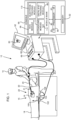
- Fig. 1 is a schematic illustration of an invasive medical procedure using apparatus 12
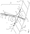
- Fig. 2 is a schematic illustration of a distal end 22 of a probe 20 used in the apparatus, according to an embodiment of the present invention.
- Probe 20 acts as a catheter, and is also referred to herein as catheter 20.
- the procedure is performed by a medical professional 14, and in the description hereinbelow the procedure is assumed to comprise characterization of a portion of tissue 15 of an internal organ of a human patient 18, the internal organ herein being assumed, by way of example, to comprise a myocardium 16 of the heart of a human patient 18.
- the characterization typically includes determination of the thickness of the portion of tissue being investigated, i.e., determination of a distance between a front or proximal surface 19 of the tissue, and a rear or distal surface 23 of the tissue.
- professional 14 inserts probe 20 into a sheath 21 that has been pre-positioned in a lumen of the patient.
- Sheath 21 is positioned so that distal end 22 of the probe enters the heart of the patient, and is in a region 17 surrounded by tissue 15. Region 17 contains blood being pumped by the heart.
- Probe 20 comprises a single tubular element 30, which terminates at distal end 22 of the probe at a tubular termination 34.
- three or more flexible branches 38 splay from termination 34 (for simplicity, Fig. 2 only illustrates two such branches) .
- there are five branches 38 as in the Pentaray ® catheter produced by Biosense Webster of 33 Technology Drive, Irvine, CA 92618 USA, and the Pentaray ® catheter may be used in a disclosed embodiment of the present invention.
- embodiments of the present invention may comprise any number of flexible branches greater than two.
- Each branch 38 comprises at least one electrode 42, and there are typically two or more electrodes 42 on each branch.
- Pentaray ® catheter there are four electrodes in each branch. In one such Pentaray catheter the spacing between each of the four electrodes is 4 mm. In another Pentaray ® catheter, the spacing between the two distal electrodes is 2 mm, between the two proximal electrodes is also 2 mm, and between the two central electrodes is 6 mm.
- a position sensor 46 is fixedly located within element 30, near termination 34. As is described in more detail below, the sensor generates signals which enable the location and orientation of the sensor itself, and thus of fixed elements within the distal end, to be tracked.
- a fiber optic 50 is incorporated within element 30, the fiber optic having a fiber optic distal end 54 at substantially the same position as termination 34. As is also described in more detail below, fiber optic 50 is configured to transmit ultrasound pulses, so that fiber optic distal end 54 acts as both a transmission port and a receiving port for the ultrasound pulses, and is herein also referred to as transceiver port 54.
- Transceiver port 54 transmits the ultrasound pulses externally to distal end 22 in a narrow cone having boundaries schematically shown by broken lines 57.
- the cone has an axis of symmetry corresponding to an axis of symmetry axis 51 of element 30, and for simplicity in the description herein the pulses are assumed to be transmitted along axis 51.
- Port 54 also receives ultrasound pulses (external to the distal end) travelling along the same axis.
- fiber optic 50 is incorporated into an existing "off-the-shelf" catheter.
- fiber optic 50 may be fed through the irrigation channel of an existing Pentaray ® catheter.
- fiber optic 50 can also be configured, by having one or more optical gratings incorporated into the fiber optic to act as a location and orientation sensor for distal end 22.
- fiber optic 50 uses fiber optic shape sensing (FOSS) technology, as is known in the art.
- FOSS fiber optic shape sensing
- the FOSS technology analyzes light diffracted from the gratings to estimate a location and an orientation of the gratings. It will be understood that if fiber optic 50 is configured as a location and orientation sensor, it may be used as well as, or in place of, position sensor 46.
- Apparatus 12 is controlled by a system processor 66, which is located in an operating console 68 of the apparatus.
- Console 68 comprises controls 69 which are used by professional 14 to communicate with the processor.
- the software for processor 66 may be downloaded to the processor in electronic form, over a network, for example and stored in a memory 52 in communication with the processor. Alternatively or additionally, the software may be provided on non-transitory tangible media, such as optical, magnetic, or electronic storage media.
- the track of distal end 22 is typically displayed on a three-dimensional representation 80 of the heart of patient 18 that is displayed on a screen 82.
- System processor 66 comprises real-time noise reduction circuitry 85, typically configured as a field programmable gate array (FPGA), followed by an analog-to-digital (A/D)) signal conversion integrated circuit 87.
- the processor can pass the signal from A/D circuit 87 to another processor and/or can be programmed to perform at least one algorithm disclosed herein, the algorithm comprising steps described hereinbelow.
- the processor uses circuitry 85 and circuit 87, as well as features of modules which are described in more detail below, in order to perform the algorithm.
- bank 90 In order to operate apparatus 12, the algorithm of processor 66 communicates with a module bank 90, which has a number of modules used by the processor to operate the apparatus.
- bank 90 comprises an electrocardiograph (ECG) module 96 which acquires and analyzes signals from electrodes 42, and a distal end tracking module 98 which receives and analyzes signals from position sensor 46, and which uses the signal analysis to generate a location and an orientation of distal end 22.
- ECG electrocardiograph
- sensor 46 comprises one or more coils which provide the sensor signals in response to magnetic fields traversing the coils.
- tracking module 98 in addition to receiving and analyzing signals from sensor 46, tracking module 98 also controls radiators 102, 104, and 106 which radiate the magnetic fields traversing sensor 46.
- the radiators are positioned in proximity to myocardium 16, are configured to radiate alternating magnetic fields into a region in proximity to the myocardium, and define a frame of reference 108 for the location and orientation determined by the sensor signals.
- the Carto ® system referred to above uses such a magnetic tracking system.
- Position sensors other than the coil type described above for sensor 46 are known in the art.
- a position sensor may be configured from multiple electrodes, and currents traversing the electrodes, and/or voltages measured at the electrodes, may be used to determine the location and orientation of the position sensor.
- fiber optic 50 may be configured as a position sensor.
- sensor 46 is a coil type as described above, and that module 98 is configured to control magnetic field radiators 102, 104, and 106, and to receive and analyze the resulting signals from the sensor.
- the description may be adapted, mutatis mutandis, to include changing the functioning of distal end tracking module 98, if position sensor 46 is not a coil type, and/or if fiber optic 50 is configured as a position sensor.
- Electrode tracking module 110 identifies and tracks the locations of electrodes 42 by any method known in the art, for example by measuring electrode voltages when the electrodes are in an electric field, and/or by measuring currents from the electrodes. Both of these systems use skin patches on patient 18, to generate the electric field, and to receive the currents from the electrodes. Electrodes 42 thus act as location sensors, and are herein also referred to as location sensors 42. The locations of location sensors 42 are measured relative to a frame of reference defined by the skin patches, and processor 66 registers this frame of reference with frame of reference 108 of radiators 102, 104, and 106, by methods well known in the art. For clarity the skin patches are not shown in Fig. 1 .
- Tracking module 110 is also configured to determine if a given identified electrode 42 contacts tissue 15, typically by observing a change in impedance between the identified electrode and a grounding patch (not shown in Fig. 1 ) when the electrode contacts the tissue.
- the Carto ® system implements the electrode identification and tracking functionality, and the contact functionality, described herein.
- Ultrasound module 112 comprises an ultrasound transducer 114 which generates ultrasound pulses, and the module conveys the pulses to fiber optic 50.
- Transducer 114 typically comprises a piezoelectric crystal.
- the pulses have an approximate length of 2 ns, and the frequency of a pulse is in a range between approximately 6 MHz and approximately 33 MHz.
- the pulses are emitted from fiber optic distal end 54, as described above. As is also described above, reflected pulses are received by distal end 54. These pulses are transferred to module 112 and to transducer 114, and the module is configured to measure the time of flight (TOF) of the pulses, between transmission from and reception by end 54.
- TOF time of flight
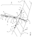
- Fig. 3 is a schematic illustration of an alternate distal end 222 of probe 20, according to an embodiment of the present invention. Apart from the differences described below, the operation of distal end 222 is generally similar to that of distal end 22 ( Fig. 2 ), and elements indicated by the same reference numerals in both distal end 22 and 222 are generally similar in construction and in operation.
- distal end 222 comprises an ultrasound transducer 224, which in some embodiments may comprise a piezoelectric crystal.
- Transducer 224 is substantially similar to transducer 114, and in embodiments comprising distal end 222, transducer 114 is not operative, and is typically not present, in module 112.
- Transducer 224 is located at termination 34 of element 30, and, as for distal end 54, transmits ultrasound pulses along axis 51.
- Transducer 224 is connected by cabling 226 to ultrasound module 112, and the module is configured to provide suitable signals via the cabling to cause transducer 224 to transmit the ultrasound pulses from end 34.
- the module is also configured to acquire, via the cabling, signals generated by transducer 224 in response to reflected ultrasound pulses received by the transducer.
- transducer 224 acts as an ultrasound transmission and receiving port, and is also referred to herein as transducer port 224.
- module 112 is configured to measure the TOF between transmission of the pulses and receipt of the reflected pulses via port 224.
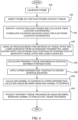
- Fig. 4 is a flowchart of steps performed for operation of apparatus 12. Except as otherwise stated, in the following description of the steps probe 20 is assumed to have distal end 22, and the description may be adapted, mutatis mutandis, if probe 20 has distal end 222.
- probe 20 is calibrated, by methods well known in the art, so that processor 66 is able to equate signals from sensor 46 with the orientation of axis 51, and with the position of termination 34, measured in frame of reference 108.
- step 230 professional 14 inserts probe 20 into proximity with tissue 15, until a plurality, typically three or more, of electrodes 42 contact the tissue.
- Processor 66 and module 110 determine that electrodes 42 make contact with tissue 15, as described above, and the processor may present a notification of the contact to the professional on screen 82.
- processor 66 and module 110 identify each contacting electrode 42 and calculate their respective location coordinates in frame of reference 108.
- the processor then formulates an initial equation for a surface having the best fit to the location coordinates.
- processor 66 invokes module 112 to generate an ultrasound pulse and emit it from transceiver port 54 at a time T 0 , recorded by the processor.
- the pulse travels through the blood of region 17, along axis 51 so that axis 51 corresponds to the direction of the pulse.
- the pulse continues along axis 51 until it strikes a point A of proximal surface 19, so that point A is an intersection of the proximal surface with the axis.
- point A because of the change in characteristics between blood and tissue, causing a difference in the speed of sound in the two materials, the pulse splits so that there is a partially reflected pulse and a partially transmitted pulse.
- a section of the reflected pulse is received at port 54, and the received pulse is detected by module 112, using transducer 114, which records a time T 1 at which the pulse is received.
- the processor uses the time of flight of the pulse, (T 1 -T 0 ), and an assumed speed of sound in blood, the processor calculates a distance of point A from termination 34. In one embodiment the speed of sound in blood is assumed to be 1578 ms -1 .
- the processor In addition to finding the distance of A from termination 34, the processor also finds the direction of A from the termination, by finding the direction, i.e., the orientation, of axis 51 from signals acquired from sensor 46. As is explained above, the processor is able to calculate the position of termination 34 in frame of reference 108 from the sensor 46 signals. Thus, in step 234 processor 66 finds the position of point A in frame of reference 108.
- the processor uses the overall time of flight of the pulse, (T 2 - T 0 ), the calculated distance of A to termination 34, and an assumed speed of sound in tissue 15, the processor calculates a distance of point B from termination 34.
- the speed of sound in tissue is assumed to be 1540 ms -1 . Because point B is on axis 51, in step 234 the processor is also able to find the position of point B in frame of reference 108.
- processor 66 calculates an apparent thickness of tissue 15 as the distance AB.
- distance AB is typically not the thickness of the tissue, since usually line segment AB is not normal to surface 19.
- the processor applies a correction to the value AB in order to find a corrected value of the tissue thickness.
- processor 66 applies the position of point A, determined in step 234, to update the equation for surface 19 determined in step 232. From the updated equation, processor 66 calculates an orientation of front surface 19 at point A, by determining an orientation angle ⁇ of a tangent surface 62 (shown as a broken line in the figure) to the front surface in frame of reference 108.
- a normal calculation step 240 from the updated surface equation and the orientation of the front surface found in step 238, the processor calculates a direction, measured in frame of reference 108, for a normal AN to surface 19 at point A. From the direction of normal AN, the processor calculates an inclination angle ⁇ (0 ⁇ ⁇ ⁇ 90°) between the normal and axis 51. Typically ⁇ ⁇ 45°.
- a final adjust tissue thickness step 242 the processor projects the distance AB onto normal AN, so forming a line segment AC.
- location sensors 42 comprise electrodes
- the scope of the present invention comprises location sensors formed from other elements, such as coils generating location signals in response to magnetic fields from radiators 102, 104, and 106.
Landscapes
- Health & Medical Sciences (AREA)
- Life Sciences & Earth Sciences (AREA)
- Engineering & Computer Science (AREA)
- Veterinary Medicine (AREA)
- Animal Behavior & Ethology (AREA)
- Public Health (AREA)
- General Health & Medical Sciences (AREA)
- Biophysics (AREA)
- Biomedical Technology (AREA)
- Heart & Thoracic Surgery (AREA)
- Surgery (AREA)
- Molecular Biology (AREA)
- Medical Informatics (AREA)
- Pathology (AREA)
- Physics & Mathematics (AREA)
- Radiology & Medical Imaging (AREA)
- Nuclear Medicine, Radiotherapy & Molecular Imaging (AREA)
- Computer Vision & Pattern Recognition (AREA)
- Cardiology (AREA)
- Physiology (AREA)
- Oral & Maxillofacial Surgery (AREA)
- Dentistry (AREA)
- Vascular Medicine (AREA)
- Human Computer Interaction (AREA)
- Pulmonology (AREA)
- Anesthesiology (AREA)
- Hematology (AREA)
- Ultra Sonic Daignosis Equipment (AREA)
- Measurement Of Velocity Or Position Using Acoustic Or Ultrasonic Waves (AREA)
- Measurement Of Length, Angles, Or The Like Using Electric Or Magnetic Means (AREA)
- Optical Transform (AREA)
- Measurement And Recording Of Electrical Phenomena And Electrical Characteristics Of The Living Body (AREA)
Claims (15)
- Gerät zum Mapping endokardialer Charakteristika unter der Oberfläche, wobei das Gerät umfasst:eine Sonde (20), umfassend ein distales Ende (22, 222), das konfiguriert ist, um in die Nähe von Gewebe eines inneren Organs eines menschlichen Patienten gebracht zu werden;einen Positionssensor (46), der an dem distalen Ende befestigt ist und konfiguriert ist, um Positionssignale zu generieren, die einen Ort und eine Orientierung des distalen Endes angeben;einen Ultraschallwandler (114, 224), der konfiguriert ist, um einen Ultraschallimpuls in eine Richtung der Orientierung des distalen Endes zu senden und Reflexionen des Ultraschallimpulses von dem Gewebe zu empfangen;eine Vielzahl von Ortssensoren (42), die an dem distalen Ende der Sonde befestigt und konfiguriert sind, um eine Oberfläche des Gewebes (19) an jeweiligen Orten in der Nähe des distalen Endes zu kontaktieren und jeweilige Ortssignale auszugeben, welche die jeweiligen Orte angeben; undeinen Prozessor (66), der konfiguriert ist zum Identifizieren von ersten und zweiten Reflexionen des Ultraschallimpulses, die von vorderen beziehungsweise rückseitigen Oberflächen des Gewebes empfangen wurden;Verarbeiten der Ortssignale, um einen Orientierungswinkel der vorderen Oberfläche des Gewebes in der Nähe des distalen Endes zu finden; undSchätzen einer Dicke des Gewebes entlang einer Achse senkrecht zu der vorderen Oberfläche basierend auf einer Zeit, die zwischen dem Empfang der ersten und der zweiten Reflexionen verstrichen ist, und einer Neigung der Richtung der Orientierung des distalen Endes relativ zu dem Orientierungswinkel der vorderen Oberfläche.
- Gerät nach Anspruch 1, und umfassend eine Faseroptik (50), die an dem distalen Ende befestigt ist, wobei die Faseroptik ein proximales Ende der Faseroptik, das an den Ultraschallwandler gekoppelt ist, und ein distales Ende der Faseroptik (54) aufweist, das sich an einem distalen Endteil (34) des distalen Endes befindet, und konfiguriert ist, um die Ultraschallimpulse zu senden und die Reflexionen der Ultraschallimpulse zu empfangen.
- Gerät nach Anspruch 2, wobei die Faseroptik ein oder mehrere optische Gitter umfasst, die so konfiguriert sind, dass gebeugtes Licht von den Gittern den Ort und die Orientierung des distalen Endes angibt, so dass das eine oder die mehreren optischen Gitter als weiterer Positionssensor fungieren.
- Gerät nach Anspruch 1, wobei der Positionssensor mindestens eine Spule umfasst, die konfiguriert ist, um die Positionssignale in Reaktion auf ein Magnetfeld zu generieren, das den Sensor quert.
- Gerät nach Anspruch 1, wobei der Positionssensor ein oder mehrere optische Gitter umfasst, die in einer Faseroptik gebildet sind, die sich in dem distalen Ende befinden, und wobei gebeugtes Licht aus den Gittern den Ort und die Orientierung des distalen Endes angibt.
- Gerät nach Anspruch 1, und umfassend mindestens drei flexible Zweige, die sich von einem Endteil des distalen Endes der Sonde aus spreizen, und wobei die Ortssensoren Elektroden umfassen, die an den flexiblen Zweigen befestigt sind.
- Gerät nach Anspruch 6, wobei mindestens eine Elektrode (42) an jedem flexiblen Zweig befestigt ist.
- Gerät nach Anspruch 1, wobei der Positionssensor mindestens eine Spule umfasst, die konfiguriert ist, um die Positionssignale in Reaktion auf ein Magnetfeld zu generieren, das die mindestens eine Spule quert.
- Gerät nach Anspruch 1, und umfassend mindestens drei flexible Zweige, die sich von einem Endteil des distalen Endes der Sonde aus spreizen, und wobei die Ortssensoren Spulen umfassen, die an den flexiblen Zweigen befestigt sind.
- Gerät nach Anspruch 9, wobei mindestens eine Spule an jedem flexiblen Zweig befestigt ist.
- Gerät nach Anspruch 1, wobei der Prozessor konfiguriert ist, um basierend auf einer Lichtlaufzeit der ersten Reflexion eine Position eines Kreuzungspunkts der vorderen Oberfläche des Gewebes mit einer Achse der Sonde zu berechnen.
- Gerät nach Anspruch 11, wobei der Prozessor konfiguriert ist, um eine Gleichung für die vordere Oberfläche basierend auf der Position des Kreuzungspunkts und der jeweiligen Orte zu formulieren.
- Gerät nach Anspruch 12, wobei der Prozessor konfiguriert ist, um den Orientierungswinkel der vorderen Oberfläche an dem Kreuzungspunkt unter Verwendung der Gleichung zu berechnen.
- Gerät nach Anspruch 1, wobei der Prozessor konfiguriert ist, um die Dicke des Gewebes als Projektion einer scheinbaren Gewebedicke auf die Achse zu schätzen, und wobei der Prozessor die scheinbare Gewebedicke in Reaktion auf die verstrichene Zeit berechnet.
- Gerät nach Anspruch 1, wobei das innere Organ ein Herz des menschlichen Patienten umfasst.
Applications Claiming Priority (2)
| Application Number | Priority Date | Filing Date | Title |
|---|---|---|---|
| US201862776841P | 2018-12-07 | 2018-12-07 | |
| US16/673,025 US20200178929A1 (en) | 2018-12-07 | 2019-11-04 | Mapping endocardial sub-surface characteristics |
Publications (2)
| Publication Number | Publication Date |
|---|---|
| EP3662841A1 EP3662841A1 (de) | 2020-06-10 |
| EP3662841B1 true EP3662841B1 (de) | 2023-03-15 |
Family
ID=68808149
Family Applications (1)
| Application Number | Title | Priority Date | Filing Date |
|---|---|---|---|
| EP19214088.7A Active EP3662841B1 (de) | 2018-12-07 | 2019-12-06 | Abbildung von endokardialen unteroberflächeneigenschaften |
Country Status (5)
| Country | Link |
|---|---|
| US (1) | US20200178929A1 (de) |
| EP (1) | EP3662841B1 (de) |
| JP (1) | JP7423289B2 (de) |
| CN (1) | CN111281434A (de) |
| IL (1) | IL270700B2 (de) |
Families Citing this family (3)
| Publication number | Priority date | Publication date | Assignee | Title |
|---|---|---|---|---|
| CN109846548A (zh) * | 2019-04-01 | 2019-06-07 | 浙江大学 | 一种实时监测的超声与射频消融二合一导管 |
| WO2025176612A1 (en) * | 2024-02-22 | 2025-08-28 | Koninklijke Philips N.V. | Wearable ultrasound patches |
| CN119405416B (zh) * | 2024-11-26 | 2025-10-31 | 上海魅丽纬叶医疗科技有限公司 | 消融组件、射频消融导管及制造方法 |
Family Cites Families (9)
| Publication number | Priority date | Publication date | Assignee | Title |
|---|---|---|---|---|
| US5350377A (en) * | 1992-10-26 | 1994-09-27 | Ultrasonic Sensing & Monitoring Systems, Inc. | Medical catheter using optical fibers that transmit both laser energy and ultrasonic imaging signals |
| US6773402B2 (en) | 2001-07-10 | 2004-08-10 | Biosense, Inc. | Location sensing with real-time ultrasound imaging |
| US10143398B2 (en) * | 2005-04-26 | 2018-12-04 | Biosense Webster, Inc. | Registration of ultrasound data with pre-acquired image |
| US8926528B2 (en) | 2008-08-06 | 2015-01-06 | Biosense Webster, Inc. | Single-axis sensors on flexible backbone |
| US20110028848A1 (en) * | 2009-07-31 | 2011-02-03 | Cem Shaquer | Methods and Apparatus for Detecting and Mapping Tissue Interfaces |
| WO2012122517A2 (en) * | 2011-03-10 | 2012-09-13 | Acutus Medical, Inc. | Device and method for the geometric determination of electrical dipole densities on the cardiac wall |
| EP2911589A1 (de) * | 2012-10-23 | 2015-09-02 | Koninklijke Philips N.V. | Vorrichtung zur bestimmung einer räumlichen konfiguration |
| EP3424414A1 (de) | 2013-04-12 | 2019-01-09 | Koninklijke Philips N.V. | Formerfassende ultraschallsonde zur fraktionsflussreservesimulation |
| US10646197B2 (en) | 2016-07-06 | 2020-05-12 | Biosense Webster (Israel) Ltd. | Ascertaining tissue thickness |
-
2019
- 2019-11-04 US US16/673,025 patent/US20200178929A1/en active Pending
- 2019-11-17 IL IL270700A patent/IL270700B2/en unknown
- 2019-12-06 CN CN201911256706.3A patent/CN111281434A/zh active Pending
- 2019-12-06 EP EP19214088.7A patent/EP3662841B1/de active Active
- 2019-12-06 JP JP2019221015A patent/JP7423289B2/ja active Active
Also Published As
| Publication number | Publication date |
|---|---|
| CN111281434A (zh) | 2020-06-16 |
| JP7423289B2 (ja) | 2024-01-29 |
| EP3662841A1 (de) | 2020-06-10 |
| US20200178929A1 (en) | 2020-06-11 |
| IL270700B1 (en) | 2024-01-01 |
| IL270700A (en) | 2020-06-30 |
| JP2020089736A (ja) | 2020-06-11 |
| IL270700B2 (en) | 2024-05-01 |
Similar Documents
| Publication | Publication Date | Title |
|---|---|---|
| US11116582B2 (en) | Apparatus for determining a motion relation | |
| US8428691B2 (en) | Method and apparatus for localizing an ultrasound catheter | |
| EP1626660B1 (de) | Systeme zur registrierung eines ultraschallbilds in einem dreidimensionalen koordinatensystem | |
| WO2005038481A1 (en) | System for determining the location of a medical probe using a reference transducer array | |
| US20030231789A1 (en) | Computer generated representation of the imaging pattern of an imaging device | |
| JP2008535560A (ja) | 身体ボリュームにおける誘導介入的医療デバイスのための3次元イメージング | |
| KR20070115630A (ko) | 위치 측정에 대한 모델에 기초한 교정 | |
| EP3266380B1 (de) | Ermittlung von gewebedicke | |
| KR20190133109A (ko) | 벌룬 카테터의 임피던스 위치 측정치의 스케일링 | |
| GB2329709A (en) | Catheter localisation system | |
| EP3662841B1 (de) | Abbildung von endokardialen unteroberflächeneigenschaften | |
| EP3563763B1 (de) | Verbesserte auflösung der aktiven spannungsortung (avl) | |
| EP3968861A1 (de) | Ultraschallsystem und verfahren zur verfolgung der bewegung eines objekts | |
| JP7305448B2 (ja) | 音響ファントム及び心内超音波局在カテーテルのための方法 | |
| JP7247055B2 (ja) | 能動電流位置(acl)における静電容量効果の低減 | |
| CN115398476A (zh) | 使用皮肤组织的超声测量值进行的解剖图像与位置跟踪系统的术前配准 | |
| EP3189785B1 (de) | Gewebetiefenschätzung unter verwendung von torgesteuerten ultraschall- und kraftmessungen | |
| IL288226B1 (en) | Ear-nose-throat (ENT) navigable shaver with ferromagnetic components | |
| CA3050405A1 (en) | Acoustic phantom and method for intracardiac ultrasound localization catheter | |
| KR20110078279A (ko) | 다중 의료용 영상 시스템에 적용 가능한 기준 표식 장치 |
Legal Events
| Date | Code | Title | Description |
|---|---|---|---|
| PUAI | Public reference made under article 153(3) epc to a published international application that has entered the european phase |
Free format text: ORIGINAL CODE: 0009012 |
|
| STAA | Information on the status of an ep patent application or granted ep patent |
Free format text: STATUS: THE APPLICATION HAS BEEN PUBLISHED |
|
| AK | Designated contracting states |
Kind code of ref document: A1 Designated state(s): AL AT BE BG CH CY CZ DE DK EE ES FI FR GB GR HR HU IE IS IT LI LT LU LV MC MK MT NL NO PL PT RO RS SE SI SK SM TR |
|
| AX | Request for extension of the european patent |
Extension state: BA ME |
|
| STAA | Information on the status of an ep patent application or granted ep patent |
Free format text: STATUS: REQUEST FOR EXAMINATION WAS MADE |
|
| 17P | Request for examination filed |
Effective date: 20200928 |
|
| RBV | Designated contracting states (corrected) |
Designated state(s): AL AT BE BG CH CY CZ DE DK EE ES FI FR GB GR HR HU IE IS IT LI LT LU LV MC MK MT NL NO PL PT RO RS SE SI SK SM TR |
|
| GRAP | Despatch of communication of intention to grant a patent |
Free format text: ORIGINAL CODE: EPIDOSNIGR1 |
|
| STAA | Information on the status of an ep patent application or granted ep patent |
Free format text: STATUS: GRANT OF PATENT IS INTENDED |
|
| GRAJ | Information related to disapproval of communication of intention to grant by the applicant or resumption of examination proceedings by the epo deleted |
Free format text: ORIGINAL CODE: EPIDOSDIGR1 |
|
| STAA | Information on the status of an ep patent application or granted ep patent |
Free format text: STATUS: REQUEST FOR EXAMINATION WAS MADE |
|
| INTG | Intention to grant announced |
Effective date: 20221116 |
|
| GRAP | Despatch of communication of intention to grant a patent |
Free format text: ORIGINAL CODE: EPIDOSNIGR1 |
|
| STAA | Information on the status of an ep patent application or granted ep patent |
Free format text: STATUS: GRANT OF PATENT IS INTENDED |
|
| INTC | Intention to grant announced (deleted) | ||
| INTG | Intention to grant announced |
Effective date: 20230103 |
|
| GRAS | Grant fee paid |
Free format text: ORIGINAL CODE: EPIDOSNIGR3 |
|
| GRAA | (expected) grant |
Free format text: ORIGINAL CODE: 0009210 |
|
| STAA | Information on the status of an ep patent application or granted ep patent |
Free format text: STATUS: THE PATENT HAS BEEN GRANTED |
|
| AK | Designated contracting states |
Kind code of ref document: B1 Designated state(s): AL AT BE BG CH CY CZ DE DK EE ES FI FR GB GR HR HU IE IS IT LI LT LU LV MC MK MT NL NO PL PT RO RS SE SI SK SM TR |
|
| REG | Reference to a national code |
Ref country code: CH Ref legal event code: EP Ref country code: GB Ref legal event code: FG4D |
|
| REG | Reference to a national code |
Ref country code: DE Ref legal event code: R096 Ref document number: 602019026371 Country of ref document: DE |
|
| REG | Reference to a national code |
Ref country code: IE Ref legal event code: FG4D |
|
| REG | Reference to a national code |
Ref country code: AT Ref legal event code: REF Ref document number: 1553531 Country of ref document: AT Kind code of ref document: T Effective date: 20230415 |
|
| REG | Reference to a national code |
Ref country code: LT Ref legal event code: MG9D |
|
| REG | Reference to a national code |
Ref country code: NL Ref legal event code: MP Effective date: 20230315 |
|
| PG25 | Lapsed in a contracting state [announced via postgrant information from national office to epo] |
Ref country code: RS Free format text: LAPSE BECAUSE OF FAILURE TO SUBMIT A TRANSLATION OF THE DESCRIPTION OR TO PAY THE FEE WITHIN THE PRESCRIBED TIME-LIMIT Effective date: 20230315 Ref country code: NO Free format text: LAPSE BECAUSE OF FAILURE TO SUBMIT A TRANSLATION OF THE DESCRIPTION OR TO PAY THE FEE WITHIN THE PRESCRIBED TIME-LIMIT Effective date: 20230615 Ref country code: LV Free format text: LAPSE BECAUSE OF FAILURE TO SUBMIT A TRANSLATION OF THE DESCRIPTION OR TO PAY THE FEE WITHIN THE PRESCRIBED TIME-LIMIT Effective date: 20230315 Ref country code: LT Free format text: LAPSE BECAUSE OF FAILURE TO SUBMIT A TRANSLATION OF THE DESCRIPTION OR TO PAY THE FEE WITHIN THE PRESCRIBED TIME-LIMIT Effective date: 20230315 Ref country code: HR Free format text: LAPSE BECAUSE OF FAILURE TO SUBMIT A TRANSLATION OF THE DESCRIPTION OR TO PAY THE FEE WITHIN THE PRESCRIBED TIME-LIMIT Effective date: 20230315 |
|
| REG | Reference to a national code |
Ref country code: AT Ref legal event code: MK05 Ref document number: 1553531 Country of ref document: AT Kind code of ref document: T Effective date: 20230315 |
|
| PG25 | Lapsed in a contracting state [announced via postgrant information from national office to epo] |
Ref country code: SE Free format text: LAPSE BECAUSE OF FAILURE TO SUBMIT A TRANSLATION OF THE DESCRIPTION OR TO PAY THE FEE WITHIN THE PRESCRIBED TIME-LIMIT Effective date: 20230315 Ref country code: NL Free format text: LAPSE BECAUSE OF FAILURE TO SUBMIT A TRANSLATION OF THE DESCRIPTION OR TO PAY THE FEE WITHIN THE PRESCRIBED TIME-LIMIT Effective date: 20230315 Ref country code: GR Free format text: LAPSE BECAUSE OF FAILURE TO SUBMIT A TRANSLATION OF THE DESCRIPTION OR TO PAY THE FEE WITHIN THE PRESCRIBED TIME-LIMIT Effective date: 20230616 Ref country code: FI Free format text: LAPSE BECAUSE OF FAILURE TO SUBMIT A TRANSLATION OF THE DESCRIPTION OR TO PAY THE FEE WITHIN THE PRESCRIBED TIME-LIMIT Effective date: 20230315 |
|
| PG25 | Lapsed in a contracting state [announced via postgrant information from national office to epo] |
Ref country code: SM Free format text: LAPSE BECAUSE OF FAILURE TO SUBMIT A TRANSLATION OF THE DESCRIPTION OR TO PAY THE FEE WITHIN THE PRESCRIBED TIME-LIMIT Effective date: 20230315 Ref country code: RO Free format text: LAPSE BECAUSE OF FAILURE TO SUBMIT A TRANSLATION OF THE DESCRIPTION OR TO PAY THE FEE WITHIN THE PRESCRIBED TIME-LIMIT Effective date: 20230315 Ref country code: PT Free format text: LAPSE BECAUSE OF FAILURE TO SUBMIT A TRANSLATION OF THE DESCRIPTION OR TO PAY THE FEE WITHIN THE PRESCRIBED TIME-LIMIT Effective date: 20230717 Ref country code: ES Free format text: LAPSE BECAUSE OF FAILURE TO SUBMIT A TRANSLATION OF THE DESCRIPTION OR TO PAY THE FEE WITHIN THE PRESCRIBED TIME-LIMIT Effective date: 20230315 Ref country code: EE Free format text: LAPSE BECAUSE OF FAILURE TO SUBMIT A TRANSLATION OF THE DESCRIPTION OR TO PAY THE FEE WITHIN THE PRESCRIBED TIME-LIMIT Effective date: 20230315 Ref country code: CZ Free format text: LAPSE BECAUSE OF FAILURE TO SUBMIT A TRANSLATION OF THE DESCRIPTION OR TO PAY THE FEE WITHIN THE PRESCRIBED TIME-LIMIT Effective date: 20230315 Ref country code: AT Free format text: LAPSE BECAUSE OF FAILURE TO SUBMIT A TRANSLATION OF THE DESCRIPTION OR TO PAY THE FEE WITHIN THE PRESCRIBED TIME-LIMIT Effective date: 20230315 |
|
| PG25 | Lapsed in a contracting state [announced via postgrant information from national office to epo] |
Ref country code: SK Free format text: LAPSE BECAUSE OF FAILURE TO SUBMIT A TRANSLATION OF THE DESCRIPTION OR TO PAY THE FEE WITHIN THE PRESCRIBED TIME-LIMIT Effective date: 20230315 Ref country code: PL Free format text: LAPSE BECAUSE OF FAILURE TO SUBMIT A TRANSLATION OF THE DESCRIPTION OR TO PAY THE FEE WITHIN THE PRESCRIBED TIME-LIMIT Effective date: 20230315 Ref country code: IS Free format text: LAPSE BECAUSE OF FAILURE TO SUBMIT A TRANSLATION OF THE DESCRIPTION OR TO PAY THE FEE WITHIN THE PRESCRIBED TIME-LIMIT Effective date: 20230715 |
|
| REG | Reference to a national code |
Ref country code: DE Ref legal event code: R097 Ref document number: 602019026371 Country of ref document: DE |
|
| PLBE | No opposition filed within time limit |
Free format text: ORIGINAL CODE: 0009261 |
|
| STAA | Information on the status of an ep patent application or granted ep patent |
Free format text: STATUS: NO OPPOSITION FILED WITHIN TIME LIMIT |
|
| PG25 | Lapsed in a contracting state [announced via postgrant information from national office to epo] |
Ref country code: SI Free format text: LAPSE BECAUSE OF FAILURE TO SUBMIT A TRANSLATION OF THE DESCRIPTION OR TO PAY THE FEE WITHIN THE PRESCRIBED TIME-LIMIT Effective date: 20230315 Ref country code: DK Free format text: LAPSE BECAUSE OF FAILURE TO SUBMIT A TRANSLATION OF THE DESCRIPTION OR TO PAY THE FEE WITHIN THE PRESCRIBED TIME-LIMIT Effective date: 20230315 |
|
| 26N | No opposition filed |
Effective date: 20231218 |
|
| REG | Reference to a national code |
Ref country code: CH Ref legal event code: PL |
|
| PG25 | Lapsed in a contracting state [announced via postgrant information from national office to epo] |
Ref country code: LU Free format text: LAPSE BECAUSE OF NON-PAYMENT OF DUE FEES Effective date: 20231206 |
|
| PG25 | Lapsed in a contracting state [announced via postgrant information from national office to epo] |
Ref country code: MC Free format text: LAPSE BECAUSE OF FAILURE TO SUBMIT A TRANSLATION OF THE DESCRIPTION OR TO PAY THE FEE WITHIN THE PRESCRIBED TIME-LIMIT Effective date: 20230315 |
|
| REG | Reference to a national code |
Ref country code: BE Ref legal event code: MM Effective date: 20231231 |
|
| PG25 | Lapsed in a contracting state [announced via postgrant information from national office to epo] |
Ref country code: MC Free format text: LAPSE BECAUSE OF FAILURE TO SUBMIT A TRANSLATION OF THE DESCRIPTION OR TO PAY THE FEE WITHIN THE PRESCRIBED TIME-LIMIT Effective date: 20230315 Ref country code: LU Free format text: LAPSE BECAUSE OF NON-PAYMENT OF DUE FEES Effective date: 20231206 |
|
| REG | Reference to a national code |
Ref country code: IE Ref legal event code: MM4A |
|
| PG25 | Lapsed in a contracting state [announced via postgrant information from national office to epo] |
Ref country code: IE Free format text: LAPSE BECAUSE OF NON-PAYMENT OF DUE FEES Effective date: 20231206 |
|
| PG25 | Lapsed in a contracting state [announced via postgrant information from national office to epo] |
Ref country code: BE Free format text: LAPSE BECAUSE OF NON-PAYMENT OF DUE FEES Effective date: 20231231 |
|
| PG25 | Lapsed in a contracting state [announced via postgrant information from national office to epo] |
Ref country code: CH Free format text: LAPSE BECAUSE OF NON-PAYMENT OF DUE FEES Effective date: 20231231 |
|
| PG25 | Lapsed in a contracting state [announced via postgrant information from national office to epo] |
Ref country code: IE Free format text: LAPSE BECAUSE OF NON-PAYMENT OF DUE FEES Effective date: 20231206 Ref country code: CH Free format text: LAPSE BECAUSE OF NON-PAYMENT OF DUE FEES Effective date: 20231231 Ref country code: BE Free format text: LAPSE BECAUSE OF NON-PAYMENT OF DUE FEES Effective date: 20231231 |
|
| PG25 | Lapsed in a contracting state [announced via postgrant information from national office to epo] |
Ref country code: BG Free format text: LAPSE BECAUSE OF FAILURE TO SUBMIT A TRANSLATION OF THE DESCRIPTION OR TO PAY THE FEE WITHIN THE PRESCRIBED TIME-LIMIT Effective date: 20230315 |
|
| PG25 | Lapsed in a contracting state [announced via postgrant information from national office to epo] |
Ref country code: BG Free format text: LAPSE BECAUSE OF FAILURE TO SUBMIT A TRANSLATION OF THE DESCRIPTION OR TO PAY THE FEE WITHIN THE PRESCRIBED TIME-LIMIT Effective date: 20230315 |
|
| PGFP | Annual fee paid to national office [announced via postgrant information from national office to epo] |
Ref country code: DE Payment date: 20241029 Year of fee payment: 6 |
|
| PGFP | Annual fee paid to national office [announced via postgrant information from national office to epo] |
Ref country code: GB Payment date: 20241031 Year of fee payment: 6 |
|
| PGFP | Annual fee paid to national office [announced via postgrant information from national office to epo] |
Ref country code: FR Payment date: 20241111 Year of fee payment: 6 |
|
| PGFP | Annual fee paid to national office [announced via postgrant information from national office to epo] |
Ref country code: IT Payment date: 20241112 Year of fee payment: 6 |
|
| PG25 | Lapsed in a contracting state [announced via postgrant information from national office to epo] |
Ref country code: CY Free format text: LAPSE BECAUSE OF FAILURE TO SUBMIT A TRANSLATION OF THE DESCRIPTION OR TO PAY THE FEE WITHIN THE PRESCRIBED TIME-LIMIT; INVALID AB INITIO Effective date: 20191206 |
|
| PG25 | Lapsed in a contracting state [announced via postgrant information from national office to epo] |
Ref country code: HU Free format text: LAPSE BECAUSE OF FAILURE TO SUBMIT A TRANSLATION OF THE DESCRIPTION OR TO PAY THE FEE WITHIN THE PRESCRIBED TIME-LIMIT; INVALID AB INITIO Effective date: 20191206 |