EP3662836A1 - Radiation image pickup device and radiation image pickup system - Google Patents
Radiation image pickup device and radiation image pickup system Download PDFInfo
- Publication number
- EP3662836A1 EP3662836A1 EP18841501.2A EP18841501A EP3662836A1 EP 3662836 A1 EP3662836 A1 EP 3662836A1 EP 18841501 A EP18841501 A EP 18841501A EP 3662836 A1 EP3662836 A1 EP 3662836A1
- Authority
- EP
- European Patent Office
- Prior art keywords
- radiation
- imaging
- image
- energy
- image signal
- Prior art date
- Legal status (The legal status is an assumption and is not a legal conclusion. Google has not performed a legal analysis and makes no representation as to the accuracy of the status listed.)
- Granted
Links
Images


Classifications
-
- A—HUMAN NECESSITIES
- A61—MEDICAL OR VETERINARY SCIENCE; HYGIENE
- A61B—DIAGNOSIS; SURGERY; IDENTIFICATION
- A61B6/00—Apparatus or devices for radiation diagnosis; Apparatus or devices for radiation diagnosis combined with radiation therapy equipment
- A61B6/48—Diagnostic techniques
- A61B6/482—Diagnostic techniques involving multiple energy imaging
-
- A—HUMAN NECESSITIES
- A61—MEDICAL OR VETERINARY SCIENCE; HYGIENE
- A61B—DIAGNOSIS; SURGERY; IDENTIFICATION
- A61B6/00—Apparatus or devices for radiation diagnosis; Apparatus or devices for radiation diagnosis combined with radiation therapy equipment
- A61B6/52—Devices using data or image processing specially adapted for radiation diagnosis
- A61B6/5211—Devices using data or image processing specially adapted for radiation diagnosis involving processing of medical diagnostic data
- A61B6/5229—Devices using data or image processing specially adapted for radiation diagnosis involving processing of medical diagnostic data combining image data of a patient, e.g. combining a functional image with an anatomical image
- A61B6/5235—Devices using data or image processing specially adapted for radiation diagnosis involving processing of medical diagnostic data combining image data of a patient, e.g. combining a functional image with an anatomical image combining images from the same or different ionising radiation imaging techniques, e.g. PET and CT
-
- A—HUMAN NECESSITIES
- A61—MEDICAL OR VETERINARY SCIENCE; HYGIENE
- A61B—DIAGNOSIS; SURGERY; IDENTIFICATION
- A61B6/00—Apparatus or devices for radiation diagnosis; Apparatus or devices for radiation diagnosis combined with radiation therapy equipment
- A61B6/52—Devices using data or image processing specially adapted for radiation diagnosis
- A61B6/5258—Devices using data or image processing specially adapted for radiation diagnosis involving detection or reduction of artifacts or noise
-
- A—HUMAN NECESSITIES
- A61—MEDICAL OR VETERINARY SCIENCE; HYGIENE
- A61B—DIAGNOSIS; SURGERY; IDENTIFICATION
- A61B6/00—Apparatus or devices for radiation diagnosis; Apparatus or devices for radiation diagnosis combined with radiation therapy equipment
- A61B6/54—Control of apparatus or devices for radiation diagnosis
- A61B6/542—Control of apparatus or devices for radiation diagnosis involving control of exposure
-
- G—PHYSICS
- G01—MEASURING; TESTING
- G01N—INVESTIGATING OR ANALYSING MATERIALS BY DETERMINING THEIR CHEMICAL OR PHYSICAL PROPERTIES
- G01N23/00—Investigating or analysing materials by the use of wave or particle radiation, e.g. X-rays or neutrons, not covered by groups G01N3/00 – G01N17/00, G01N21/00 or G01N22/00
- G01N23/02—Investigating or analysing materials by the use of wave or particle radiation, e.g. X-rays or neutrons, not covered by groups G01N3/00 – G01N17/00, G01N21/00 or G01N22/00 by transmitting the radiation through the material
- G01N23/04—Investigating or analysing materials by the use of wave or particle radiation, e.g. X-rays or neutrons, not covered by groups G01N3/00 – G01N17/00, G01N21/00 or G01N22/00 by transmitting the radiation through the material and forming images of the material
-
- G—PHYSICS
- G01—MEASURING; TESTING
- G01N—INVESTIGATING OR ANALYSING MATERIALS BY DETERMINING THEIR CHEMICAL OR PHYSICAL PROPERTIES
- G01N2223/00—Investigating materials by wave or particle radiation
- G01N2223/40—Imaging
- G01N2223/401—Imaging image processing
Definitions
- the present invention relates to a radiation imaging apparatus and a radiation imaging system.
- a radiation imaging apparatus using a flat panel detector (FPD) made of a semiconductor material is widely used.
- FPD flat panel detector
- One known imaging method using an FPD is a method of acquiring an energy subtraction image using radiations of different energy components.
- PTL 1 shows a radiation imaging apparatus using a DXA (Dual X-ray Absorptiometry) method that repetitively irradiates an object with high-energy radiation and low-energy radiation and performs imaging.
- the detection value (count) of radiation at the time of low-energy radiation imaging is much smaller than the count of radiation at the time of high-energy radiation imaging, as compared to an object of an average physical constitution.
- PTL 1 shows that to equalize the counts of radiations detected in imaging using high-energy radiation and low-energy radiation, the ratio of the times over which low-energy radiation and high-energy radiation are repetitively alternately generated by a radiation generation unit is controlled.
- control is performed to make the time over which low-energy radiation higher than that of high-energy radiation, thereby equalizing the counts of detected radiations.
- a noise amount included in a high-energy radiation image and that in a low-energy radiation image can be different.
- Noise included in an energy subtraction image can depend on the noise amount of the radiation image obtained using high-energy radiation and that in the radiation image obtained using low-energy radiation. To improve the quality of the energy subtraction image, the noise amount included in the high-energy image and the noise amount included in the low-energy image need to be taken into consideration.
- a radiation imaging apparatus comprising a detection unit configured to generate an image signal according to radiation emitted by a radiation source, an image processing unit, and a control unit, characterized in that the control unit performs first imaging and second imaging performed after the first imaging using radiations of different energies, the image processing unit generates an energy subtraction image using a first image signal generated by the detection unit in the first imaging and a second image signal generated by the detection unit in the second imaging, and the second imaging is performed under a radiation irradiation condition according to a noise amount included in the first image signal.
- the above-described means provides a technique advantageous in improving the quality of an energy subtraction image in a radiation imaging apparatus.
- Radiation according to the present invention can include not only ⁇ -rays, ⁇ -rays, and ⁇ -rays that are beams generated by particles (including photons) emitted by radioactive decay but also beams having equal or more energy, for example, X-rays, particle rays, and cosmic rays.
- Fig. 1 is a view showing an example of the arrangement of a radiation imaging system 110 using a radiation imaging apparatus 100 according to the first embodiment of the present invention.
- the radiation imaging system 110 is configured to electrically capture an optical image converted from radiation to obtain an electrical signal (image signal) used to generate a radiation image.
- the radiation imaging system 110 includes, for example, the radiation imaging apparatus 100, a radiation source 101, an exposure control unit 103, an imaging condition setting unit 104, and an image display unit 107.
- the radiation imaging apparatus 100 includes, for example, a detection unit 102, an image processing unit 106, and a control unit 105 configured to control the constituent elements of the radiation imaging apparatus 100.
- the radiation source 101 irradiates an object 109 with radiation.
- the radiation source 101 includes a radiation generation unit (tube bulb) that generates radiation, and a collimator that defines the beam divergence angle of the radiation generated by the radiation generation unit.
- the exposure control unit 103 controls the dose of radiation emitted by the radiation source 101.
- the detection unit 102 detects radiation that enters through the object 109, and generates an image signal.
- the control unit 105 controls the detection unit 102 based on a signal output from the imaging condition setting unit 104. In addition, the control unit 105 controls irradiation of radiation from the radiation source 101 via the exposure control unit 103.
- the imaging condition setting unit 104 can be a computer configured to input an imaging condition such as a radiation irradiation condition used to capture a radiation image by a user, or a display that displays an input imaging condition or the like.
- the image processing unit 106 generates an energy subtraction image using a plurality of image signals output from the detection unit 102.
- an example in which the imaging condition setting unit 104 is arranged outside the radiation imaging apparatus 100 is shown.
- some or all of the functions of the imaging condition setting unit 104 may be provided in the radiation imaging apparatus 100.
- the image processing unit 106 is arranged in the radiation imaging apparatus 100 is shown.
- some or all of image processes performed by the image processing unit 106 may be performed by another image processing unit arranged outside the radiation imaging apparatus 100.
- the image display unit 107 can be a monitor such as a display that displays image data output from the image processing unit 106.
- step S201 radiation irradiation conditions at the time of imaging, such as the irradiation dose of radiation and the tube voltage and the tube current of the radiation source 101, are set in accordance with a user operation on the imaging condition setting unit 104.
- the user may select the radiation irradiation conditions from combinations of radiation irradiation conditions used in two imaging operations set in advance.
- the radiation imaging apparatus 100 may include a storage unit 108 that stores in advance the combinations of radiation irradiation conditions used in two imaging operations performed in the two-shot method.
- imaging of an object may be performed in advance using a low dose, and an object thickness or the like may be estimated from the transmission dose.
- the control unit 105 may select an appropriate combination of radiation irradiation conditions based on the estimated object thickness and the like.
- Fig. 3 shows an example of combinations of radiation irradiation conditions used in imaging.
- the radiation irradiation conditions include, for example, the values of the tube voltage and the tube current of the radiation source 101, which decide the energy value of radiation, and a radiation irradiation time (the charge accumulation time in the detection unit 102).
- the combinations of the irradiation conditions can be created in accordance with, for example, a noise amount assumed to be included in an image signal.
- the object is a human body.
- the object need not always be a human body.
- objects may be classified by materials such as an organic compound, a light metal, and a heavy metal, and the combinations of radiation irradiation conditions may be held in the storage unit 108.
- functions may be provided such that the user inputs the information of the thickness to the imaging condition setting unit 104 based on the above-described classification, and the control unit 105 selects recommended radiation irradiation conditions from the storage unit 108 and sets the conditions.
- step S202 the control unit 105 captures a radiation image under radiation irradiation conditions for a high-energy image in synchronism with the exposure control unit 103.
- step S203 a radiation image is captured under radiation irradiation conditions for a low-energy image, as in step S202.
- imaging is performed first using high-energy radiation, and imaging using low-energy radiation is then performed.
- the order is not limited to this. Imaging by low-energy radiation may be performed first, and imaging by high-energy radiation may be performed later.
- step S204 an energy subtraction image is generated. More specifically, the image processing unit 106 generates an energy subtraction image using an image signal generated by the detection unit 102 in the imaging using the high-energy radiation and an image signal generated by the detection unit 102 in the imaging using the low-energy radiation.
- step S205 the energy subtraction image output from the image processing unit 106, the high-energy image and the low-energy image before energy subtraction processing, and the like are displayed on the image display unit 107. The user can perform diagnosis or the like using the images displayed on the image display unit 107.
- the noise amount of the energy subtraction image after four arithmetic operations of the high-energy image and the low-energy image can be calculated by equations (1), (2), and (3) below.
- Mi is the pixel value of the high-energy image
- ⁇ 1 is the noise value of the high-energy image
- M 2 is the pixel value of the low-energy image
- ⁇ 2 is the noise value of the low-energy image.
- M 1 ⁇ ⁇ 1 ⁇ M 2 ⁇ ⁇ 2 M 1 ⁇ M 2 ⁇ ⁇ 1 2 ⁇ ⁇ 2 2
- M 1 ⁇ ⁇ 1 ⁇ M 2 ⁇ ⁇ 2 M 1 ⁇ M 2 ⁇ M 2 ⁇ ⁇ 1 2 + M 1 ⁇ ⁇ 2 2
- M 1 ⁇ ⁇ 1 ⁇ M 2 ⁇ ⁇ 2 M 1 M 2 ⁇ 1 M 2 ⁇ ⁇ 1 2 + M 1 M 2 ⁇ ⁇ 2 2
- Bone suppression processing is image processing of removing a bone portion from a radiation image obtained using a low-energy image and a high-energy image.
- image processing is often performed using equation (4).
- M cor is the pixel value of the energy subtraction image
- ⁇ cor is the noise value of the energy subtraction image
- I is the irradiation dose of radiation
- ⁇ is a correction coefficient (constant) used to add a weight to the high-energy image and the low-energy image.
- M cor ⁇ ⁇ cor M 1 ⁇ ⁇ 1 ⁇ ⁇ ⁇ M 2 ⁇ ⁇ 2
- ⁇ cor ⁇ 1 2 + ⁇ ⁇ ⁇ 2 2
- equation (7) needs to be satisfied. ⁇ 1 2 + ⁇ ⁇ ⁇ 2 2 ⁇ 2 ⁇ 1 ⁇ 2 ⁇ 1 2 + ⁇ ⁇ ⁇ 2 2
- Expression (9) represents that since the number of arriving radiation particles complies with a Poisson distribution, noise in the radiation image is proportional to the square root of the transmission dose.
- the noise values ⁇ 1 and ⁇ 2 representing the noise amounts of the high-energy image and the low-energy image change for each thickness or substance of the object. For this reason, imaging cannot necessarily be performed under ideal radiation irradiation conditions.
- the combination of radiation irradiation conditions is created such that, for example, ⁇ 1 /( ⁇ ⁇ ⁇ 2 ) falls within the range of 1/3 to 3.
- Fig. 4 is a graph showing the transition of the noise amount of the energy subtraction image with respect to the noise amount of the low-energy image and the noise amount of the high-energy image.
- the setting can be done such that ⁇ 1 /( ⁇ ⁇ ⁇ 2 ) falls within the range of 1/3 to 3, the increase of the noise amount can be suppressed to about 10% or less from the optimum noise amount of the energy subtraction image.
- the combination of radiation irradiation conditions may be set based on the relational expressions (equations (1), (2), and (3)) of error propagation in four arithmetic operations.
- the processing can also be applied to a case in which a bone image and a soft tissue image are separated by solving nonlinear simultaneous equations using the low-energy image and the high-energy image or a case in which an electron density image and an effective atomic number image are separated.
- the energy value of radiation is changed by changing the tube voltage and the tube current of the radiation source 101.
- the present invention is not limited to this. For example, images by radiations of different energies may be acquired based on the presence/absence of insertion of a beam hardening filter or the like without changing the tube voltage and the tube current of the radiation source 101.
- the combination of radiation irradiation conditions is selected such that imaging using low-energy radiation is performed under radiation irradiation conditions according to the noise amount included in the image signal generated by imaging using high-energy radiation. This can suppress noise of an energy subtraction image and acquire an energy subtraction image of high quality.
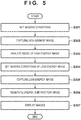
- Fig. 5 is a flowchart of processing from image capturing of an object to display of an energy subtraction image using a radiation imaging apparatus 100 according to the second embodiment of the present invention.
- the radiation imaging apparatus 100 and a radiation imaging system 110 can be similar to those of the above-described first embodiment, and a description thereof will be omitted here.
- step S301 radiation irradiation conditions at the time of imaging, such as the energy value of radiation such as the tube voltage and the tube current of a radiation source 101 and a radiation irradiation time (the charge accumulation time in a detection unit 102) are set in accordance with a user operation on an imaging condition setting unit 104.
- the user sets the radiation irradiation conditions of at least the imaging operation (in this embodiment, imaging of a high-energy image using high-energy radiation) performed first in two imaging operations.
- the imaging operation in this embodiment, imaging of a high-energy image using high-energy radiation
- the radiation imaging apparatus 100 may include a storage unit 108 that stores in advance radiation irradiation conditions to be used in the first imaging operation. If the radiation imaging apparatus 100 includes the storage unit 108, in accordance with the object, the user may select appropriate conditions from the radiation irradiation conditions stored in the storage unit 108. In addition, the radiation imaging apparatus 100 may include a camera or a gauge used to measure the thickens of the object. In this case, in accordance with information such as the detected thickness of the object, a control unit 105 may select appropriate conditions from the radiation irradiation conditions stored in the storage unit 108.
- imaging of the object may be performed in advance using a low dose
- the object thickness or the like may be estimated from the transmission dose, and the control unit 105 may decide appropriate radiation irradiation conditions based on the estimated object thickness or the like.
- step 302 imaging of a high-energy image using high-energy radiation is performed.
- the image signal of the captured high-energy image is output from the detection unit 102 to an image processing unit 106.
- the control unit 105 analyzes the noise amount included in the image signal of the high-energy image acquired and output to the image processing unit 106 in step S302.
- the image signal of a predetermined region in the detection unit 102 may be analyzed.
- the control unit 105 may select the image signal of an arbitrary portion of the detection unit 102 using a region extraction technique or the like.
- the control unit 105 may select, as the predetermined region, a region with a small transmission dose, such as a lumbar spine where a bone thickness is large.
- a region with a small transmission dose such as a lumbar spine where a bone thickness is large.
- an appropriate filter or the like may be arranged in the visual field of the detection unit 102, and the user may select, as the predetermined region, the place where the filter is arranged. If a filter or the like is arranged in the visual field, the control unit 105 may recognize the place where the filter is arranged as a region with a small transmission dose and select it as the predetermined region.
- the control unit 105 performs processing of, for example, obtaining the standard deviation (noise) of the image signal of the predetermined region in the image signal of the high-energy image, thereby deciding the noise amount included in the image signal of the high-energy image.
- step S304 based on the noise amount decided from the analysis result of the noise amount included in the high-energy image in step S303, the control unit 105 decides radiation irradiation conditions of imaging of a low-energy image using low-energy radiation.
- the control unit 105 may decide both the energy value (the tube voltage, the tube current, and the like) of radiation in the imaging using low-energy radiation and the radiation irradiation time.
- the control unit 105 may select appropriate radiation irradiation conditions from the radiation irradiation conditions stored in the storage unit 108, thereby deciding the radiation irradiation conditions of the low-energy image.
- step S301 temporary radiation irradiation conditions (the energy value of radiation and the radiation irradiation time) of imaging of the low-energy image are selected in advance.
- step S304 the control unit 105 may correct at least one of an energy value of radiation and the radiation irradiation time in the temporary radiation irradiation conditions in accordance with the decided noise amount, thereby deciding the radiation irradiation conditions of the low-energy image.
- the radiation irradiation conditions at the time of imaging of the low-energy image are obtained by a method similar to that of the above-described first embodiment such that the noise amount of an energy subtraction image is made small or minimized if possible.
- the radiation irradiation conditions of the low-energy image are decided based on the relational expressions (equations (1), (2), and (3)) of error propagation in four arithmetic operations.
- the control unit 105 controls the detection unit 102 and an exposure control unit 103 and performs imaging of the low-energy image using low-energy radiation.
- the irradiation dose of radiation may be controlled using an AEC (Auto Exposure Control) function of stopping radiation irradiation at a desired transmission dose or a photo timer.
- the control unit 105 may output, to the exposure control unit 103, a signal to stop radiation irradiation from the radiation source 101.
- the exposure control unit 103 controls the radiation source 101 to stop radiation irradiation.
- step S306 the image processing unit 106 performs energy subtraction processing using the image signal of the high-energy image and the image signal of the low-energy image output from the detection unit 102.
- step S307 an energy subtraction image obtained by the energy subtraction processing is output from the image processing unit 106 and displayed on an image display unit 107. At this time, not only the energy subtraction image but also the high-energy image and the low-energy image may be output from the image processing unit 106 to the image display unit 107 and displayed.
- imaging using high-energy radiation is performed first, and imaging using low-energy radiation is performed later.
- the imaging order is not limited to this. Additionally, in the above-described embodiments, an example in which imaging is performed twice is shown. However, imaging may be performed three or more times, and energy subtraction processing may be performed.
- the noise amount included in the image signal generated by imaging using high-energy radiation is decided. After that, setting of the radiation irradiation conditions of imaging using low-energy radiation is done in accordance with the noise amount. This can suppress noise of an energy subtraction image and acquire an energy subtraction image of high quality.
Landscapes
- Health & Medical Sciences (AREA)
- Life Sciences & Earth Sciences (AREA)
- Engineering & Computer Science (AREA)
- Medical Informatics (AREA)
- Pathology (AREA)
- General Health & Medical Sciences (AREA)
- Physics & Mathematics (AREA)
- Heart & Thoracic Surgery (AREA)
- Biophysics (AREA)
- Nuclear Medicine, Radiotherapy & Molecular Imaging (AREA)
- Radiology & Medical Imaging (AREA)
- Biomedical Technology (AREA)
- High Energy & Nuclear Physics (AREA)
- Molecular Biology (AREA)
- Surgery (AREA)
- Animal Behavior & Ethology (AREA)
- Optics & Photonics (AREA)
- Public Health (AREA)
- Veterinary Medicine (AREA)
- Computer Vision & Pattern Recognition (AREA)
- Chemical & Material Sciences (AREA)
- Analytical Chemistry (AREA)
- Biochemistry (AREA)
- General Physics & Mathematics (AREA)
- Immunology (AREA)
- Apparatus For Radiation Diagnosis (AREA)
Abstract
Description
- The present invention relates to a radiation imaging apparatus and a radiation imaging system.
- In medical image diagnosis or nondestructive inspection, a radiation imaging apparatus using a flat panel detector (FPD) made of a semiconductor material is widely used. One known imaging method using an FPD is a method of acquiring an energy subtraction image using radiations of different energy components.
PTL 1 shows a radiation imaging apparatus using a DXA (Dual X-ray Absorptiometry) method that repetitively irradiates an object with high-energy radiation and low-energy radiation and performs imaging. Generally, in an object with a thick body, the detection value (count) of radiation at the time of low-energy radiation imaging is much smaller than the count of radiation at the time of high-energy radiation imaging, as compared to an object of an average physical constitution.PTL 1 shows that to equalize the counts of radiations detected in imaging using high-energy radiation and low-energy radiation, the ratio of the times over which low-energy radiation and high-energy radiation are repetitively alternately generated by a radiation generation unit is controlled. - PTL 1: Japanese Patent Laid-Open No.
2009-131564 - In
PTL 1, control is performed to make the time over which low-energy radiation higher than that of high-energy radiation, thereby equalizing the counts of detected radiations. However, even if the counts of detected radiations equal, a noise amount included in a high-energy radiation image and that in a low-energy radiation image can be different. Noise included in an energy subtraction image can depend on the noise amount of the radiation image obtained using high-energy radiation and that in the radiation image obtained using low-energy radiation. To improve the quality of the energy subtraction image, the noise amount included in the high-energy image and the noise amount included in the low-energy image need to be taken into consideration. - It is an object of the present invention to provide a technique advantageous in improving the quality of an energy subtraction image in a radiation imaging apparatus.
- In consideration of the above-described problem, according to an aspect of the present invention, there is provided a radiation imaging apparatus comprising a detection unit configured to generate an image signal according to radiation emitted by a radiation source, an image processing unit, and a control unit, characterized in that the control unit performs first imaging and second imaging performed after the first imaging using radiations of different energies, the image processing unit generates an energy subtraction image using a first image signal generated by the detection unit in the first imaging and a second image signal generated by the detection unit in the second imaging, and the second imaging is performed under a radiation irradiation condition according to a noise amount included in the first image signal.
- The above-described means provides a technique advantageous in improving the quality of an energy subtraction image in a radiation imaging apparatus.
- Other features and advantages of the present invention will be apparent from the following descriptions taken in conjunction with the accompanying drawings, in which like reference characters designate the same or similar parts throughout the figures thereof.
- The accompanying drawings, which are incorporated in and constitute a part of the specification, illustrate embodiments of the invention and, together with the description, serve to explain the principles of the invention.
-
Fig. 1 is a view showing an example of the arrangement of a radiation imaging system using a radiation imaging apparatus according to an embodiment of the present invention; -
Fig. 2 is a flowchart showing the procedure of imaging of an energy subtraction image using the radiation imaging apparatus shown inFig. 1 ; -
Fig. 3 is a view showing an example of radiation irradiation conditions in imaging of the energy subtraction image shown inFig. 2 ; -
Fig. 4 is a view showing the relationship between noise in a high-energy image and a low-energy image and noise in an energy subtraction image; and -
Fig. 5 is a flowchart showing the procedure of imaging of an energy subtraction image using the radiation imaging apparatus shown inFig. 1 . - Detailed embodiments of a radiation imaging apparatus according to the present invention will now be described with reference to the accompanying drawings. Radiation according to the present invention can include not only α-rays, β-rays, and γ-rays that are beams generated by particles (including photons) emitted by radioactive decay but also beams having equal or more energy, for example, X-rays, particle rays, and cosmic rays.
- The arrangement and operation of a radiation imaging apparatus according to an embodiment of the present invention will be described with reference to
Figs. 1 to 4 .Fig. 1 is a view showing an example of the arrangement of aradiation imaging system 110 using aradiation imaging apparatus 100 according to the first embodiment of the present invention. Theradiation imaging system 110 is configured to electrically capture an optical image converted from radiation to obtain an electrical signal (image signal) used to generate a radiation image. Theradiation imaging system 110 includes, for example, theradiation imaging apparatus 100, aradiation source 101, anexposure control unit 103, an imagingcondition setting unit 104, and animage display unit 107. Theradiation imaging apparatus 100 includes, for example, adetection unit 102, animage processing unit 106, and acontrol unit 105 configured to control the constituent elements of theradiation imaging apparatus 100. - The
radiation source 101 irradiates anobject 109 with radiation. Theradiation source 101 includes a radiation generation unit (tube bulb) that generates radiation, and a collimator that defines the beam divergence angle of the radiation generated by the radiation generation unit. Theexposure control unit 103 controls the dose of radiation emitted by theradiation source 101. Thedetection unit 102 detects radiation that enters through theobject 109, and generates an image signal. Thecontrol unit 105 controls thedetection unit 102 based on a signal output from the imagingcondition setting unit 104. In addition, thecontrol unit 105 controls irradiation of radiation from theradiation source 101 via theexposure control unit 103. The imagingcondition setting unit 104 can be a computer configured to input an imaging condition such as a radiation irradiation condition used to capture a radiation image by a user, or a display that displays an input imaging condition or the like. Theimage processing unit 106 generates an energy subtraction image using a plurality of image signals output from thedetection unit 102. In the arrangement shown inFig. 1 , an example in which the imagingcondition setting unit 104 is arranged outside theradiation imaging apparatus 100 is shown. However, some or all of the functions of the imagingcondition setting unit 104 may be provided in theradiation imaging apparatus 100. Additionally, in the arrangement shown inFig. 1 , an example in which theimage processing unit 106 is arranged in theradiation imaging apparatus 100 is shown. However, some or all of image processes performed by theimage processing unit 106 may be performed by another image processing unit arranged outside theradiation imaging apparatus 100. Theimage display unit 107 can be a monitor such as a display that displays image data output from theimage processing unit 106. - Processing from image capturing of an object to display of an energy subtraction image will be described next with reference to
Fig. 2 . A case in which the energy subtraction image is acquired using a two-shot method will be described here. However, adaptation to an imaging method such as a one-shot method other than the two-shot method is also possible. - First, in step S201, radiation irradiation conditions at the time of imaging, such as the irradiation dose of radiation and the tube voltage and the tube current of the
radiation source 101, are set in accordance with a user operation on the imagingcondition setting unit 104. In this case, in accordance with the conditions of the object such as the constituent substance and the thickness of the object, the user may select the radiation irradiation conditions from combinations of radiation irradiation conditions used in two imaging operations set in advance. Hence, as shown inFig. 1 , theradiation imaging apparatus 100 may include astorage unit 108 that stores in advance the combinations of radiation irradiation conditions used in two imaging operations performed in the two-shot method. In addition, to select the combination of radiation irradiation conditions, imaging of an object may be performed in advance using a low dose, and an object thickness or the like may be estimated from the transmission dose. In this case, thecontrol unit 105 may select an appropriate combination of radiation irradiation conditions based on the estimated object thickness and the like. -
Fig. 3 shows an example of combinations of radiation irradiation conditions used in imaging. The radiation irradiation conditions include, for example, the values of the tube voltage and the tube current of theradiation source 101, which decide the energy value of radiation, and a radiation irradiation time (the charge accumulation time in the detection unit 102). The combinations of the irradiation conditions can be created in accordance with, for example, a noise amount assumed to be included in an image signal. Here, the object is a human body. However, the object need not always be a human body. For example, objects may be classified by materials such as an organic compound, a light metal, and a heavy metal, and the combinations of radiation irradiation conditions may be held in thestorage unit 108. Furthermore, if the object is a compound, functions may be provided such that the user inputs the information of the thickness to the imagingcondition setting unit 104 based on the above-described classification, and thecontrol unit 105 selects recommended radiation irradiation conditions from thestorage unit 108 and sets the conditions. - When the radiation irradiation conditions are selected, in step S202, the
control unit 105 captures a radiation image under radiation irradiation conditions for a high-energy image in synchronism with theexposure control unit 103. Next, in step S203 as well, a radiation image is captured under radiation irradiation conditions for a low-energy image, as in step S202. In this embodiment, imaging is performed first using high-energy radiation, and imaging using low-energy radiation is then performed. However, the order is not limited to this. Imaging by low-energy radiation may be performed first, and imaging by high-energy radiation may be performed later. - After imaging is performed twice using radiations of different energies, in step S204, an energy subtraction image is generated. More specifically, the
image processing unit 106 generates an energy subtraction image using an image signal generated by thedetection unit 102 in the imaging using the high-energy radiation and an image signal generated by thedetection unit 102 in the imaging using the low-energy radiation. Next, in step S205, the energy subtraction image output from theimage processing unit 106, the high-energy image and the low-energy image before energy subtraction processing, and the like are displayed on theimage display unit 107. The user can perform diagnosis or the like using the images displayed on theimage display unit 107. - A method of creating the combinations of the radiation irradiation conditions shown in
Fig. 3 will be described next in detail. The noise amount of the energy subtraction image after four arithmetic operations of the high-energy image and the low-energy image can be calculated by equations (1), (2), and (3) below. Here, Mi is the pixel value of the high-energy image, ε1 is the noise value of the high-energy image, M2 is the pixel value of the low-energy image, and ε2 is the noise value of the low-energy image.


- In this specification, a case in which bone suppression processing is performed as representative processing of energy subtraction processing will be described. Bone suppression processing is image processing of removing a bone portion from a radiation image obtained using a low-energy image and a high-energy image. In bone suppression processing, generally, image processing is often performed using equation (4). Here, Mcor is the pixel value of the energy subtraction image, εcor is the noise value of the energy subtraction image, I is the irradiation dose of radiation, and α is a correction coefficient (constant) used to add a weight to the high-energy image and the low-energy image.

- By applying equation (1) to equation (4), the noise value εcor of the energy subtraction image is given by equation (5).

- According to the relational expression (inequality (6)) of arithmetic geometric mean, to minimize the noise value εcor of the energy subtraction image in equation (5), equation (7) needs to be satisfied.


- That is, equation (8) below needs to be satisfied.


- Expression (9) represents that since the number of arriving radiation particles complies with a Poisson distribution, noise in the radiation image is proportional to the square root of the transmission dose. Here, when reducing only noise in the energy subtraction image without increasing the exposure dose of the object is considered, it is possible to obtain radiation irradiation conditions using expressions (7) and (9). However, the noise values ε1 and ε2 representing the noise amounts of the high-energy image and the low-energy image change for each thickness or substance of the object. For this reason, imaging cannot necessarily be performed under ideal radiation irradiation conditions. Hence, the combination of radiation irradiation conditions is created such that, for example, ε1/(α × ε2) falls within the range of 1/3 to 3. In other words, imaging using low-energy radiation is performed under radiation irradiation conditions such that the noise amount of the image signal of imaging using low-energy radiation to which the correction coefficient is applied becomes 1/3 times or more and 3 times or less of the noise amount of the image signal of imaging using high-energy radiation.
Fig. 4 is a graph showing the transition of the noise amount of the energy subtraction image with respect to the noise amount of the low-energy image and the noise amount of the high-energy image. As is apparent fromFig. 4 , if the setting can be done such that ε1/(α × ε2) falls within the range of 1/3 to 3, the increase of the noise amount can be suppressed to about 10% or less from the optimum noise amount of the energy subtraction image. As described above, the combination of radiation irradiation conditions may be set based on the relational expressions (equations (1), (2), and (3)) of error propagation in four arithmetic operations. - In this embodiment, a form in which processing of separating a bone image and a soft tissue image is performed by performing, for example, differential processing for the low-energy image and the high-energy image has been described. However, the present invention is not limited to this form. For example, the processing can also be applied to a case in which a bone image and a soft tissue image are separated by solving nonlinear simultaneous equations using the low-energy image and the high-energy image or a case in which an electron density image and an effective atomic number image are separated. Additionally, in this embodiment, the energy value of radiation is changed by changing the tube voltage and the tube current of the
radiation source 101. However, the present invention is not limited to this. For example, images by radiations of different energies may be acquired based on the presence/absence of insertion of a beam hardening filter or the like without changing the tube voltage and the tube current of theradiation source 101. - In this embodiment, the combination of radiation irradiation conditions is selected such that imaging using low-energy radiation is performed under radiation irradiation conditions according to the noise amount included in the image signal generated by imaging using high-energy radiation. This can suppress noise of an energy subtraction image and acquire an energy subtraction image of high quality.
- The arrangement and operation of a radiation imaging apparatus according to an embodiment of the present invention will be described with reference to
Fig. 5. Fig. 5 is a flowchart of processing from image capturing of an object to display of an energy subtraction image using aradiation imaging apparatus 100 according to the second embodiment of the present invention. Theradiation imaging apparatus 100 and aradiation imaging system 110 can be similar to those of the above-described first embodiment, and a description thereof will be omitted here. - First, in step S301, radiation irradiation conditions at the time of imaging, such as the energy value of radiation such as the tube voltage and the tube current of a
radiation source 101 and a radiation irradiation time (the charge accumulation time in a detection unit 102) are set in accordance with a user operation on an imagingcondition setting unit 104. In this case, in accordance with the conditions of the object such as the constituent substance and the thickness of the object, the user sets the radiation irradiation conditions of at least the imaging operation (in this embodiment, imaging of a high-energy image using high-energy radiation) performed first in two imaging operations. At this time, as shown inFig. 1 , theradiation imaging apparatus 100 may include astorage unit 108 that stores in advance radiation irradiation conditions to be used in the first imaging operation. If theradiation imaging apparatus 100 includes thestorage unit 108, in accordance with the object, the user may select appropriate conditions from the radiation irradiation conditions stored in thestorage unit 108. In addition, theradiation imaging apparatus 100 may include a camera or a gauge used to measure the thickens of the object. In this case, in accordance with information such as the detected thickness of the object, acontrol unit 105 may select appropriate conditions from the radiation irradiation conditions stored in thestorage unit 108. In addition, to select the radiation irradiation conditions, imaging of the object may be performed in advance using a low dose, the object thickness or the like may be estimated from the transmission dose, and thecontrol unit 105 may decide appropriate radiation irradiation conditions based on the estimated object thickness or the like. - After the radiation irradiation conditions of the high-energy image are set in step S301, in step 302, imaging of a high-energy image using high-energy radiation is performed. The image signal of the captured high-energy image is output from the
detection unit 102 to animage processing unit 106. In step S303, thecontrol unit 105 analyzes the noise amount included in the image signal of the high-energy image acquired and output to theimage processing unit 106 in step S302. As for a region of interest to analyze the noise amount, the image signal of a predetermined region in thedetection unit 102 may be analyzed. Thecontrol unit 105 may select the image signal of an arbitrary portion of thedetection unit 102 using a region extraction technique or the like. For example, thecontrol unit 105 may select, as the predetermined region, a region with a small transmission dose, such as a lumbar spine where a bone thickness is large. Additionally, for example, an appropriate filter or the like may be arranged in the visual field of thedetection unit 102, and the user may select, as the predetermined region, the place where the filter is arranged. If a filter or the like is arranged in the visual field, thecontrol unit 105 may recognize the place where the filter is arranged as a region with a small transmission dose and select it as the predetermined region. Thecontrol unit 105 performs processing of, for example, obtaining the standard deviation (noise) of the image signal of the predetermined region in the image signal of the high-energy image, thereby deciding the noise amount included in the image signal of the high-energy image. - In step S304, based on the noise amount decided from the analysis result of the noise amount included in the high-energy image in step S303, the
control unit 105 decides radiation irradiation conditions of imaging of a low-energy image using low-energy radiation. As the radiation irradiation conditions of imaging of the low-energy image, thecontrol unit 105 may decide both the energy value (the tube voltage, the tube current, and the like) of radiation in the imaging using low-energy radiation and the radiation irradiation time. In addition, thecontrol unit 105 may select appropriate radiation irradiation conditions from the radiation irradiation conditions stored in thestorage unit 108, thereby deciding the radiation irradiation conditions of the low-energy image. Additionally, for example, in step S301, temporary radiation irradiation conditions (the energy value of radiation and the radiation irradiation time) of imaging of the low-energy image are selected in advance. Then, in step S304, thecontrol unit 105 may correct at least one of an energy value of radiation and the radiation irradiation time in the temporary radiation irradiation conditions in accordance with the decided noise amount, thereby deciding the radiation irradiation conditions of the low-energy image. The radiation irradiation conditions at the time of imaging of the low-energy image are obtained by a method similar to that of the above-described first embodiment such that the noise amount of an energy subtraction image is made small or minimized if possible. As described above, in this embodiment as well, the radiation irradiation conditions of the low-energy image are decided based on the relational expressions (equations (1), (2), and (3)) of error propagation in four arithmetic operations. - After the radiation irradiation conditions of the low-energy image are decided, in step S305, the
control unit 105 controls thedetection unit 102 and anexposure control unit 103 and performs imaging of the low-energy image using low-energy radiation. At this time, the irradiation dose of radiation may be controlled using an AEC (Auto Exposure Control) function of stopping radiation irradiation at a desired transmission dose or a photo timer. In this case, when the transmission dose of a region set in advance by the user or the like reaches a desired dose, thecontrol unit 105 may output, to theexposure control unit 103, a signal to stop radiation irradiation from theradiation source 101. In accordance with the signal, theexposure control unit 103 controls theradiation source 101 to stop radiation irradiation. - In step S306, the
image processing unit 106 performs energy subtraction processing using the image signal of the high-energy image and the image signal of the low-energy image output from thedetection unit 102. In step S307, an energy subtraction image obtained by the energy subtraction processing is output from theimage processing unit 106 and displayed on animage display unit 107. At this time, not only the energy subtraction image but also the high-energy image and the low-energy image may be output from theimage processing unit 106 to theimage display unit 107 and displayed. - In this embodiment, imaging using high-energy radiation is performed first, and imaging using low-energy radiation is performed later. However, the imaging order is not limited to this. Additionally, in the above-described embodiments, an example in which imaging is performed twice is shown. However, imaging may be performed three or more times, and energy subtraction processing may be performed.
- In this embodiment, the noise amount included in the image signal generated by imaging using high-energy radiation is decided. After that, setting of the radiation irradiation conditions of imaging using low-energy radiation is done in accordance with the noise amount. This can suppress noise of an energy subtraction image and acquire an energy subtraction image of high quality.
- The present invention is not limited to the above embodiments, and various changes and modifications can be made within the spirit and scope of the present invention. Therefore, to apprise the public of the scope of the present invention, the following claims are made.
- This application claims the benefit of Japanese Patent Application No.
2017-151760, filed August 4, 2017
Claims (14)
- A radiation imaging apparatus comprising a detection unit configured to generate an image signal according to radiation emitted by a radiation source, an image processing unit, and a control unit, characterized in that
the control unit performs first imaging and second imaging performed after the first imaging using radiations of different energies,
the image processing unit generates an energy subtraction image using a first image signal generated by the detection unit in the first imaging and a second image signal generated by the detection unit in the second imaging, and
the second imaging is performed under a radiation irradiation condition according to a noise amount included in the first image signal. - The radiation imaging apparatus according to claim 1, characterized in that the radiation imaging apparatus further comprises a storage unit configured to store in advance combinations of radiation irradiation conditions used in the first imaging and the second imaging, and
the radiation irradiation conditions of the first imaging and the second imaging are selected from the combinations in accordance with an object. - The radiation imaging apparatus according to claim 2, characterized in that the radiation irradiation conditions used in the first imaging and the second imaging include energy values of radiations and radiation irradiation times in the first imaging and the second imaging.
- The radiation imaging apparatus according to claim 2 or 3, characterized in that the combination is set based on a relational expression of error propagation in four arithmetic operations.
- The radiation imaging apparatus according to claim 1, characterized in that the control unit
decides the noise amount included in the first image signal based on a standard deviation of an image signal of a predetermined region of the first image signal in the first imaging, and
decides the radiation irradiation condition of the second imaging in accordance with the decided noise amount. - The radiation imaging apparatus according to claim 5, characterized in that the control unit decides, as the radiation irradiation condition of the second imaging, at least one of an energy value of radiation and the radiation irradiation time in the second imaging.
- The radiation imaging apparatus according to claim 5 or 6, characterized in that the radiation imaging apparatus further comprises a storage unit configured to store in advance radiation irradiation conditions used in the first imaging, and
the radiation irradiation condition of the first imaging is selected, in accordance with an object, from the radiation irradiation conditions stored in the storage unit. - The radiation imaging apparatus according to claim 7, characterized in that the radiation irradiation condition used in the first imaging includes an energy value of radiation and a radiation irradiation time in the first imaging.
- The radiation imaging apparatus according to claim 7 or 8, characterized in that the storage unit further includes the radiation irradiation condition used in the second imaging, and
the control unit corrects, in accordance with the noise amount, a temporary radiation irradiation condition selected before the second imaging, thereby deciding the radiation irradiation condition of the second imaging. - The radiation imaging apparatus according to any one of claims 5 to 9, characterized in that the control unit uses, as the image signal of the predetermined region, an image signal of a region with a small transmission dose in the first image signal.
- The radiation imaging apparatus according to any one of claims 5 to 10, characterized in that the radiation irradiation condition of the second imaging is decided based on a relational expression of error propagation in four arithmetic operations.
- The radiation imaging apparatus according to any one of claims 1 to 11, characterized in that the image processing unit applies a correction coefficient to the second image signal when generating the energy subtraction image, and
the second imaging is performed under a radiation irradiation condition such that the noise amount of the second image signal to which the correction coefficient is applied becomes not less than 1/3 times and not more than 3 times of the noise amount of the first image signal. - The radiation imaging apparatus according to any one of claims 1 to 12, characterized in that an energy value of radiation in the first imaging is higher than the energy value of radiation in the second imaging.
- A radiation imaging system comprising:a radiation imaging apparatus according to any one of claims 1 to 13; anda radiation source configured to emit radiation.
Applications Claiming Priority (2)
| Application Number | Priority Date | Filing Date | Title |
|---|---|---|---|
| JP2017151760A JP6912965B2 (en) | 2017-08-04 | 2017-08-04 | How to operate a radiation imaging device, a radiation imaging system, and a radiation imaging device |
| PCT/JP2018/021209 WO2019026409A1 (en) | 2017-08-04 | 2018-06-01 | Radiation image pickup device and radiation image pickup system |
Publications (3)
| Publication Number | Publication Date |
|---|---|
| EP3662836A1 true EP3662836A1 (en) | 2020-06-10 |
| EP3662836A4 EP3662836A4 (en) | 2021-04-14 |
| EP3662836B1 EP3662836B1 (en) | 2023-11-15 |
Family
ID=65233643
Family Applications (1)
| Application Number | Title | Priority Date | Filing Date |
|---|---|---|---|
| EP18841501.2A Active EP3662836B1 (en) | 2017-08-04 | 2018-06-01 | Radiation image pickup device and radiation image pickup system |
Country Status (4)
| Country | Link |
|---|---|
| US (1) | US11185301B2 (en) |
| EP (1) | EP3662836B1 (en) |
| JP (1) | JP6912965B2 (en) |
| WO (1) | WO2019026409A1 (en) |
Families Citing this family (9)
| Publication number | Priority date | Publication date | Assignee | Title |
|---|---|---|---|---|
| JP6882135B2 (en) | 2017-10-06 | 2021-06-02 | キヤノン株式会社 | Image processing equipment, image processing methods and programs |
| JP7245001B2 (en) | 2018-05-29 | 2023-03-23 | キヤノン株式会社 | Radiation imaging device and imaging system |
| JP7093233B2 (en) | 2018-06-07 | 2022-06-29 | キヤノン株式会社 | Radiography equipment, radiography methods and programs |
| WO2020003744A1 (en) | 2018-06-27 | 2020-01-02 | キヤノン株式会社 | Radiographic imaging apparatus, radiographic imaging method, and program |
| JP7169853B2 (en) * | 2018-11-09 | 2022-11-11 | キヤノン株式会社 | Image processing device, radiation imaging device, and image processing method |
| JP7397593B2 (en) | 2019-07-23 | 2023-12-13 | キヤノン株式会社 | Radiation imaging device, image acquisition method and program |
| JP7378245B2 (en) | 2019-08-29 | 2023-11-13 | キヤノン株式会社 | Radiation detection device, its control method, and radiation imaging system |
| JP7619821B2 (en) | 2021-02-09 | 2025-01-22 | キヤノン株式会社 | Information processing device, radiation imaging system, information processing method and program |
| JP2024025211A (en) | 2022-08-10 | 2024-02-26 | キヤノン株式会社 | Radiation imaging device, radiation imaging system, control device, radiation imaging device control method, and program for controlling the radiation imaging device |
Family Cites Families (42)
| Publication number | Priority date | Publication date | Assignee | Title |
|---|---|---|---|---|
| JPS6349142A (en) * | 1986-08-19 | 1988-03-01 | 株式会社東芝 | X-ray ct apparatus |
| US6125166A (en) * | 1998-01-13 | 2000-09-26 | Fuji Photo Film Co., Ltd. | Method of forming energy subtraction images |
| JP5389324B2 (en) | 2006-12-18 | 2014-01-15 | ジーイー・メディカル・システムズ・グローバル・テクノロジー・カンパニー・エルエルシー | X-ray tomography equipment |
| JP5220374B2 (en) * | 2007-09-27 | 2013-06-26 | ジーイー・メディカル・システムズ・グローバル・テクノロジー・カンパニー・エルエルシー | X-ray CT system |
| JP5229865B2 (en) | 2007-11-30 | 2013-07-03 | ジーイー・メディカル・システムズ・グローバル・テクノロジー・カンパニー・エルエルシー | X-ray CT system |
| JP4980862B2 (en) | 2007-12-03 | 2012-07-18 | 日立アロカメディカル株式会社 | X-ray measuring device |
| JP5535528B2 (en) * | 2009-06-12 | 2014-07-02 | ジーイー・メディカル・システムズ・グローバル・テクノロジー・カンパニー・エルエルシー | X-ray CT system |
| US8634516B2 (en) * | 2010-03-07 | 2014-01-21 | Hironori Tsukamoto | Energy subtraction imaging system, X-ray imaging apparatus, and computer readable recording medium |
| JP5814621B2 (en) | 2011-05-24 | 2015-11-17 | キヤノン株式会社 | IMAGING DEVICE, ITS CONTROL METHOD, AND IMAGING SYSTEM |
| JP5950840B2 (en) | 2012-03-16 | 2016-07-13 | キヤノン株式会社 | Radiation imaging apparatus and imaging system |
| JP5986526B2 (en) | 2012-04-06 | 2016-09-06 | キヤノン株式会社 | Radiation imaging apparatus, control method therefor, and radiation imaging system |
| JP6162937B2 (en) | 2012-08-31 | 2017-07-12 | キヤノン株式会社 | Radiation imaging apparatus, control method thereof, and control program |
| JP6041669B2 (en) | 2012-12-28 | 2016-12-14 | キヤノン株式会社 | Imaging apparatus and imaging system |
| JP5934128B2 (en) | 2013-02-28 | 2016-06-15 | キヤノン株式会社 | Radiation imaging apparatus and radiation imaging system |
| JP5986524B2 (en) | 2013-02-28 | 2016-09-06 | キヤノン株式会社 | Radiation imaging apparatus and radiation imaging system |
| JP6016673B2 (en) | 2013-02-28 | 2016-10-26 | キヤノン株式会社 | Radiation imaging apparatus and radiation imaging system |
| JP2014168205A (en) | 2013-02-28 | 2014-09-11 | Canon Inc | Radiation imaging apparatus, radiation inspection apparatus, and signal correction method and program |
| JP6161346B2 (en) | 2013-03-19 | 2017-07-12 | キヤノン株式会社 | Imaging system |
| JP6238577B2 (en) | 2013-06-05 | 2017-11-29 | キヤノン株式会社 | Radiation imaging apparatus and radiation imaging system |
| US20140361189A1 (en) | 2013-06-05 | 2014-12-11 | Canon Kabushiki Kaisha | Radiation imaging system |
| JP6376783B2 (en) | 2014-03-12 | 2018-08-22 | キヤノン株式会社 | Breast tomography apparatus and control method |
| JP6355387B2 (en) | 2014-03-31 | 2018-07-11 | キヤノン株式会社 | Imaging apparatus and imaging system |
| US9737271B2 (en) | 2014-04-09 | 2017-08-22 | Canon Kabushiki Kaisha | Radiation imaging apparatus and control method of the same |
| JP6362421B2 (en) | 2014-05-26 | 2018-07-25 | キヤノン株式会社 | Radiation imaging apparatus, control method thereof, and program |
| JP6494204B2 (en) | 2014-07-17 | 2019-04-03 | キヤノン株式会社 | Radiation imaging apparatus and radiation imaging system |
| JP6385179B2 (en) | 2014-07-18 | 2018-09-05 | キヤノン株式会社 | Radiation imaging apparatus and driving method thereof |
| JP6391388B2 (en) | 2014-09-24 | 2018-09-19 | キヤノン株式会社 | Radiation imaging device |
| JP6525579B2 (en) | 2014-12-22 | 2019-06-05 | キヤノン株式会社 | Radiation imaging apparatus and radiation imaging system |
| JP2016178533A (en) | 2015-03-20 | 2016-10-06 | キヤノン株式会社 | Radiation imaging apparatus and radiation imaging system |
| JP6573377B2 (en) | 2015-07-08 | 2019-09-11 | キヤノン株式会社 | Radiation imaging apparatus, control method thereof, and program |
| JP6573378B2 (en) | 2015-07-10 | 2019-09-11 | キヤノン株式会社 | Radiation imaging apparatus, control method thereof, and program |
| JP6674222B2 (en) | 2015-10-09 | 2020-04-01 | キヤノン株式会社 | Radiation imaging apparatus and control method of radiation imaging apparatus |
| JP6643871B2 (en) | 2015-11-13 | 2020-02-12 | キヤノン株式会社 | Radiation imaging apparatus and photon counting method |
| JP6643909B2 (en) | 2016-01-27 | 2020-02-12 | キヤノン株式会社 | Radiation imaging apparatus, control method thereof, and program |
| JP6700828B2 (en) | 2016-02-10 | 2020-05-27 | キヤノン株式会社 | Radiation imaging apparatus, driving method thereof and imaging system |
| JP2017151760A (en) | 2016-02-25 | 2017-08-31 | パイオニア株式会社 | Display device, control method, program, and storage medium |
| JP6871717B2 (en) | 2016-11-10 | 2021-05-12 | キヤノン株式会社 | Radiation imaging device, radiation imaging system and radiation imaging method |
| JP2018110794A (en) | 2017-01-13 | 2018-07-19 | キヤノン株式会社 | Information processing apparatus, radiation imaging apparatus, information processing method, and program |
| JP6974948B2 (en) | 2017-02-10 | 2021-12-01 | キヤノン株式会社 | Radiation imaging device and radiation imaging method |
| CN110869809B (en) | 2017-07-10 | 2023-07-25 | 佳能株式会社 | Radiation imaging apparatus and radiation imaging system |
| JP7038506B2 (en) * | 2017-08-25 | 2022-03-18 | キヤノン株式会社 | How to operate a radiation image pickup device, a radiation image pickup system, and a radiation image pickup device |
| JP7067912B2 (en) | 2017-12-13 | 2022-05-16 | キヤノン株式会社 | Radiation imaging device and radiation imaging system |
-
2017
- 2017-08-04 JP JP2017151760A patent/JP6912965B2/en active Active
-
2018
- 2018-06-01 WO PCT/JP2018/021209 patent/WO2019026409A1/en not_active Ceased
- 2018-06-01 EP EP18841501.2A patent/EP3662836B1/en active Active
-
2020
- 2020-01-22 US US16/749,201 patent/US11185301B2/en active Active
Also Published As
| Publication number | Publication date |
|---|---|
| JP2019030386A (en) | 2019-02-28 |
| WO2019026409A1 (en) | 2019-02-07 |
| EP3662836B1 (en) | 2023-11-15 |
| US11185301B2 (en) | 2021-11-30 |
| JP6912965B2 (en) | 2021-08-04 |
| US20200155097A1 (en) | 2020-05-21 |
| EP3662836A4 (en) | 2021-04-14 |
Similar Documents
| Publication | Publication Date | Title |
|---|---|---|
| EP3662836B1 (en) | Radiation image pickup device and radiation image pickup system | |
| US11360034B2 (en) | Radiation imaging apparatus and radiation imaging system | |
| JP7085043B2 (en) | Image processing equipment, image processing methods and programs | |
| US11826186B2 (en) | Image processing apparatus, image processing method, and program | |
| US10117628B2 (en) | Photon counting apparatus | |
| EP3342342B1 (en) | Radiation image processing method and radiographic system | |
| EP3804623B1 (en) | Radiation imaging apparatus, radiation imaging method, and program | |
| Brombal et al. | Large-area single-photon-counting CdTe detector for synchrotron radiation computed tomography: a dedicated pre-processing procedure | |
| JP2006101926A (en) | Radiation detection apparatus, radiological image diagnostic apparatus, and radiographic image generation method | |
| EP4014874B1 (en) | Image processing device, radiographic imaging system, image processing method, and program | |
| Zhu et al. | Spectral K-edge subtraction imaging | |
| US12136191B2 (en) | Image processing apparatus, image processing method, and non-transitory computer-readable storage medium | |
| Brun et al. | Single-shot K-edge subtraction x-ray discrete computed tomography with a polychromatic source and the Pixie-III detector | |
| EP3367905B1 (en) | Radiation imaging system, information processing apparatus for irradiation image, image processing method for radiation image, and program | |
| Cho et al. | The effects of photon flux on energy spectra and imaging characteristics in a photon-counting X-ray detector | |
| Atharifard et al. | Per-pixel energy calibration of photon counting detectors | |
| US20220366543A1 (en) | Image processing apparatus, image processing method, and storage medium | |
| EP3476296B1 (en) | Tomography system and method thereof | |
| EP3708082A1 (en) | Image processing device, image processing method, radiation imaging device, and method and program for controlling radiation imaging device | |
| Yao et al. | Efficacy of fixed filtration for rapid kVp‐switching dual energy x‐ray systems | |
| JP2008073342A (en) | Radiographic image capturing system and radiographic image capturing method | |
| US20220240882A1 (en) | Image processing apparatus, radiation imaging apparatus, image processing method, and non-transitory computer readable storage medium | |
| US20220323036A1 (en) | Image processing apparatus, method, and storage medium | |
| Yokhana et al. | Lab-based x-ray tomography of a cochlear implant using energy discriminating detectors for metal artefact reduction | |
| Wu et al. | Spectral CT reconstruction with weighted non-local total-variation minimization |
Legal Events
| Date | Code | Title | Description |
|---|---|---|---|
| STAA | Information on the status of an ep patent application or granted ep patent |
Free format text: STATUS: THE INTERNATIONAL PUBLICATION HAS BEEN MADE |
|
| PUAI | Public reference made under article 153(3) epc to a published international application that has entered the european phase |
Free format text: ORIGINAL CODE: 0009012 |
|
| STAA | Information on the status of an ep patent application or granted ep patent |
Free format text: STATUS: REQUEST FOR EXAMINATION WAS MADE |
|
| 17P | Request for examination filed |
Effective date: 20200304 |
|
| AK | Designated contracting states |
Kind code of ref document: A1 Designated state(s): AL AT BE BG CH CY CZ DE DK EE ES FI FR GB GR HR HU IE IS IT LI LT LU LV MC MK MT NL NO PL PT RO RS SE SI SK SM TR |
|
| AX | Request for extension of the european patent |
Extension state: BA ME |
|
| DAV | Request for validation of the european patent (deleted) | ||
| DAX | Request for extension of the european patent (deleted) | ||
| A4 | Supplementary search report drawn up and despatched |
Effective date: 20210315 |
|
| RIC1 | Information provided on ipc code assigned before grant |
Ipc: A61B 6/00 20060101AFI20210309BHEP |
|
| GRAP | Despatch of communication of intention to grant a patent |
Free format text: ORIGINAL CODE: EPIDOSNIGR1 |
|
| STAA | Information on the status of an ep patent application or granted ep patent |
Free format text: STATUS: GRANT OF PATENT IS INTENDED |
|
| INTG | Intention to grant announced |
Effective date: 20230609 |
|
| GRAS | Grant fee paid |
Free format text: ORIGINAL CODE: EPIDOSNIGR3 |
|
| GRAA | (expected) grant |
Free format text: ORIGINAL CODE: 0009210 |
|
| STAA | Information on the status of an ep patent application or granted ep patent |
Free format text: STATUS: THE PATENT HAS BEEN GRANTED |
|
| AK | Designated contracting states |
Kind code of ref document: B1 Designated state(s): AL AT BE BG CH CY CZ DE DK EE ES FI FR GB GR HR HU IE IS IT LI LT LU LV MC MK MT NL NO PL PT RO RS SE SI SK SM TR |
|
| REG | Reference to a national code |
Ref country code: CH Ref legal event code: EP Ref country code: GB Ref legal event code: FG4D |
|
| REG | Reference to a national code |
Ref country code: DE Ref legal event code: R096 Ref document number: 602018061231 Country of ref document: DE |
|
| REG | Reference to a national code |
Ref country code: IE Ref legal event code: FG4D |
|
| REG | Reference to a national code |
Ref country code: LT Ref legal event code: MG9D |
|
| REG | Reference to a national code |
Ref country code: NL Ref legal event code: MP Effective date: 20231115 |
|
| PG25 | Lapsed in a contracting state [announced via postgrant information from national office to epo] |
Ref country code: GR Free format text: LAPSE BECAUSE OF FAILURE TO SUBMIT A TRANSLATION OF THE DESCRIPTION OR TO PAY THE FEE WITHIN THE PRESCRIBED TIME-LIMIT Effective date: 20240216 |
|
| PG25 | Lapsed in a contracting state [announced via postgrant information from national office to epo] |
Ref country code: IS Free format text: LAPSE BECAUSE OF FAILURE TO SUBMIT A TRANSLATION OF THE DESCRIPTION OR TO PAY THE FEE WITHIN THE PRESCRIBED TIME-LIMIT Effective date: 20240315 |
|
| PG25 | Lapsed in a contracting state [announced via postgrant information from national office to epo] |
Ref country code: LT Free format text: LAPSE BECAUSE OF FAILURE TO SUBMIT A TRANSLATION OF THE DESCRIPTION OR TO PAY THE FEE WITHIN THE PRESCRIBED TIME-LIMIT Effective date: 20231115 |
|
| REG | Reference to a national code |
Ref country code: AT Ref legal event code: MK05 Ref document number: 1631017 Country of ref document: AT Kind code of ref document: T Effective date: 20231115 |
|
| PG25 | Lapsed in a contracting state [announced via postgrant information from national office to epo] |
Ref country code: NL Free format text: LAPSE BECAUSE OF FAILURE TO SUBMIT A TRANSLATION OF THE DESCRIPTION OR TO PAY THE FEE WITHIN THE PRESCRIBED TIME-LIMIT Effective date: 20231115 |
|
| PG25 | Lapsed in a contracting state [announced via postgrant information from national office to epo] |
Ref country code: AT Free format text: LAPSE BECAUSE OF FAILURE TO SUBMIT A TRANSLATION OF THE DESCRIPTION OR TO PAY THE FEE WITHIN THE PRESCRIBED TIME-LIMIT Effective date: 20231115 |
|
| PG25 | Lapsed in a contracting state [announced via postgrant information from national office to epo] |
Ref country code: ES Free format text: LAPSE BECAUSE OF FAILURE TO SUBMIT A TRANSLATION OF THE DESCRIPTION OR TO PAY THE FEE WITHIN THE PRESCRIBED TIME-LIMIT Effective date: 20231115 |
|
| PG25 | Lapsed in a contracting state [announced via postgrant information from national office to epo] |
Ref country code: NL Free format text: LAPSE BECAUSE OF FAILURE TO SUBMIT A TRANSLATION OF THE DESCRIPTION OR TO PAY THE FEE WITHIN THE PRESCRIBED TIME-LIMIT Effective date: 20231115 Ref country code: LT Free format text: LAPSE BECAUSE OF FAILURE TO SUBMIT A TRANSLATION OF THE DESCRIPTION OR TO PAY THE FEE WITHIN THE PRESCRIBED TIME-LIMIT Effective date: 20231115 Ref country code: IS Free format text: LAPSE BECAUSE OF FAILURE TO SUBMIT A TRANSLATION OF THE DESCRIPTION OR TO PAY THE FEE WITHIN THE PRESCRIBED TIME-LIMIT Effective date: 20240315 Ref country code: GR Free format text: LAPSE BECAUSE OF FAILURE TO SUBMIT A TRANSLATION OF THE DESCRIPTION OR TO PAY THE FEE WITHIN THE PRESCRIBED TIME-LIMIT Effective date: 20240216 Ref country code: ES Free format text: LAPSE BECAUSE OF FAILURE TO SUBMIT A TRANSLATION OF THE DESCRIPTION OR TO PAY THE FEE WITHIN THE PRESCRIBED TIME-LIMIT Effective date: 20231115 Ref country code: BG Free format text: LAPSE BECAUSE OF FAILURE TO SUBMIT A TRANSLATION OF THE DESCRIPTION OR TO PAY THE FEE WITHIN THE PRESCRIBED TIME-LIMIT Effective date: 20240215 Ref country code: AT Free format text: LAPSE BECAUSE OF FAILURE TO SUBMIT A TRANSLATION OF THE DESCRIPTION OR TO PAY THE FEE WITHIN THE PRESCRIBED TIME-LIMIT Effective date: 20231115 Ref country code: PT Free format text: LAPSE BECAUSE OF FAILURE TO SUBMIT A TRANSLATION OF THE DESCRIPTION OR TO PAY THE FEE WITHIN THE PRESCRIBED TIME-LIMIT Effective date: 20240315 |
|
| PG25 | Lapsed in a contracting state [announced via postgrant information from national office to epo] |
Ref country code: SE Free format text: LAPSE BECAUSE OF FAILURE TO SUBMIT A TRANSLATION OF THE DESCRIPTION OR TO PAY THE FEE WITHIN THE PRESCRIBED TIME-LIMIT Effective date: 20231115 Ref country code: RS Free format text: LAPSE BECAUSE OF FAILURE TO SUBMIT A TRANSLATION OF THE DESCRIPTION OR TO PAY THE FEE WITHIN THE PRESCRIBED TIME-LIMIT Effective date: 20231115 Ref country code: PL Free format text: LAPSE BECAUSE OF FAILURE TO SUBMIT A TRANSLATION OF THE DESCRIPTION OR TO PAY THE FEE WITHIN THE PRESCRIBED TIME-LIMIT Effective date: 20231115 Ref country code: NO Free format text: LAPSE BECAUSE OF FAILURE TO SUBMIT A TRANSLATION OF THE DESCRIPTION OR TO PAY THE FEE WITHIN THE PRESCRIBED TIME-LIMIT Effective date: 20240215 Ref country code: LV Free format text: LAPSE BECAUSE OF FAILURE TO SUBMIT A TRANSLATION OF THE DESCRIPTION OR TO PAY THE FEE WITHIN THE PRESCRIBED TIME-LIMIT Effective date: 20231115 Ref country code: HR Free format text: LAPSE BECAUSE OF FAILURE TO SUBMIT A TRANSLATION OF THE DESCRIPTION OR TO PAY THE FEE WITHIN THE PRESCRIBED TIME-LIMIT Effective date: 20231115 |
|
| PG25 | Lapsed in a contracting state [announced via postgrant information from national office to epo] |
Ref country code: DK Free format text: LAPSE BECAUSE OF FAILURE TO SUBMIT A TRANSLATION OF THE DESCRIPTION OR TO PAY THE FEE WITHIN THE PRESCRIBED TIME-LIMIT Effective date: 20231115 |
|
| PG25 | Lapsed in a contracting state [announced via postgrant information from national office to epo] |
Ref country code: CZ Free format text: LAPSE BECAUSE OF FAILURE TO SUBMIT A TRANSLATION OF THE DESCRIPTION OR TO PAY THE FEE WITHIN THE PRESCRIBED TIME-LIMIT Effective date: 20231115 |
|
| PG25 | Lapsed in a contracting state [announced via postgrant information from national office to epo] |
Ref country code: SK Free format text: LAPSE BECAUSE OF FAILURE TO SUBMIT A TRANSLATION OF THE DESCRIPTION OR TO PAY THE FEE WITHIN THE PRESCRIBED TIME-LIMIT Effective date: 20231115 |
|
| PG25 | Lapsed in a contracting state [announced via postgrant information from national office to epo] |
Ref country code: SM Free format text: LAPSE BECAUSE OF FAILURE TO SUBMIT A TRANSLATION OF THE DESCRIPTION OR TO PAY THE FEE WITHIN THE PRESCRIBED TIME-LIMIT Effective date: 20231115 Ref country code: SK Free format text: LAPSE BECAUSE OF FAILURE TO SUBMIT A TRANSLATION OF THE DESCRIPTION OR TO PAY THE FEE WITHIN THE PRESCRIBED TIME-LIMIT Effective date: 20231115 Ref country code: RO Free format text: LAPSE BECAUSE OF FAILURE TO SUBMIT A TRANSLATION OF THE DESCRIPTION OR TO PAY THE FEE WITHIN THE PRESCRIBED TIME-LIMIT Effective date: 20231115 Ref country code: IT Free format text: LAPSE BECAUSE OF FAILURE TO SUBMIT A TRANSLATION OF THE DESCRIPTION OR TO PAY THE FEE WITHIN THE PRESCRIBED TIME-LIMIT Effective date: 20231115 Ref country code: EE Free format text: LAPSE BECAUSE OF FAILURE TO SUBMIT A TRANSLATION OF THE DESCRIPTION OR TO PAY THE FEE WITHIN THE PRESCRIBED TIME-LIMIT Effective date: 20231115 Ref country code: DK Free format text: LAPSE BECAUSE OF FAILURE TO SUBMIT A TRANSLATION OF THE DESCRIPTION OR TO PAY THE FEE WITHIN THE PRESCRIBED TIME-LIMIT Effective date: 20231115 Ref country code: CZ Free format text: LAPSE BECAUSE OF FAILURE TO SUBMIT A TRANSLATION OF THE DESCRIPTION OR TO PAY THE FEE WITHIN THE PRESCRIBED TIME-LIMIT Effective date: 20231115 |
|
| REG | Reference to a national code |
Ref country code: DE Ref legal event code: R097 Ref document number: 602018061231 Country of ref document: DE |
|
| PLBE | No opposition filed within time limit |
Free format text: ORIGINAL CODE: 0009261 |
|
| STAA | Information on the status of an ep patent application or granted ep patent |
Free format text: STATUS: NO OPPOSITION FILED WITHIN TIME LIMIT |
|
| 26N | No opposition filed |
Effective date: 20240819 |
|
| PG25 | Lapsed in a contracting state [announced via postgrant information from national office to epo] |
Ref country code: SI Free format text: LAPSE BECAUSE OF FAILURE TO SUBMIT A TRANSLATION OF THE DESCRIPTION OR TO PAY THE FEE WITHIN THE PRESCRIBED TIME-LIMIT Effective date: 20231115 |
|
| PG25 | Lapsed in a contracting state [announced via postgrant information from national office to epo] |
Ref country code: SI Free format text: LAPSE BECAUSE OF FAILURE TO SUBMIT A TRANSLATION OF THE DESCRIPTION OR TO PAY THE FEE WITHIN THE PRESCRIBED TIME-LIMIT Effective date: 20231115 |
|
| PG25 | Lapsed in a contracting state [announced via postgrant information from national office to epo] |
Ref country code: MC Free format text: LAPSE BECAUSE OF FAILURE TO SUBMIT A TRANSLATION OF THE DESCRIPTION OR TO PAY THE FEE WITHIN THE PRESCRIBED TIME-LIMIT Effective date: 20231115 |
|
| REG | Reference to a national code |
Ref country code: CH Ref legal event code: PL |
|
| PG25 | Lapsed in a contracting state [announced via postgrant information from national office to epo] |
Ref country code: LU Free format text: LAPSE BECAUSE OF NON-PAYMENT OF DUE FEES Effective date: 20240601 |
|
| GBPC | Gb: european patent ceased through non-payment of renewal fee |
Effective date: 20240601 |
|
| PG25 | Lapsed in a contracting state [announced via postgrant information from national office to epo] |
Ref country code: IE Free format text: LAPSE BECAUSE OF NON-PAYMENT OF DUE FEES Effective date: 20240601 |
|
| PG25 | Lapsed in a contracting state [announced via postgrant information from national office to epo] |
Ref country code: BE Free format text: LAPSE BECAUSE OF NON-PAYMENT OF DUE FEES Effective date: 20240630 Ref country code: CH Free format text: LAPSE BECAUSE OF NON-PAYMENT OF DUE FEES Effective date: 20240630 |
|
| PG25 | Lapsed in a contracting state [announced via postgrant information from national office to epo] |
Ref country code: FR Free format text: LAPSE BECAUSE OF NON-PAYMENT OF DUE FEES Effective date: 20240630 |
|
| PG25 | Lapsed in a contracting state [announced via postgrant information from national office to epo] |
Ref country code: GB Free format text: LAPSE BECAUSE OF NON-PAYMENT OF DUE FEES Effective date: 20240601 |
|
| REG | Reference to a national code |
Ref country code: BE Ref legal event code: MM Effective date: 20240630 |
|
| PGFP | Annual fee paid to national office [announced via postgrant information from national office to epo] |
Ref country code: DE Payment date: 20250520 Year of fee payment: 8 |
|
| PG25 | Lapsed in a contracting state [announced via postgrant information from national office to epo] |
Ref country code: CY Free format text: LAPSE BECAUSE OF FAILURE TO SUBMIT A TRANSLATION OF THE DESCRIPTION OR TO PAY THE FEE WITHIN THE PRESCRIBED TIME-LIMIT; INVALID AB INITIO Effective date: 20180601 |
|
| PG25 | Lapsed in a contracting state [announced via postgrant information from national office to epo] |
Ref country code: FI Free format text: LAPSE BECAUSE OF FAILURE TO SUBMIT A TRANSLATION OF THE DESCRIPTION OR TO PAY THE FEE WITHIN THE PRESCRIBED TIME-LIMIT Effective date: 20231115 |
|
| PG25 | Lapsed in a contracting state [announced via postgrant information from national office to epo] |
Ref country code: HU Free format text: LAPSE BECAUSE OF FAILURE TO SUBMIT A TRANSLATION OF THE DESCRIPTION OR TO PAY THE FEE WITHIN THE PRESCRIBED TIME-LIMIT; INVALID AB INITIO Effective date: 20180601 |