EP3662802B1 - Bettreiniger - Google Patents
Bettreiniger Download PDFInfo
- Publication number
- EP3662802B1 EP3662802B1 EP19212815.5A EP19212815A EP3662802B1 EP 3662802 B1 EP3662802 B1 EP 3662802B1 EP 19212815 A EP19212815 A EP 19212815A EP 3662802 B1 EP3662802 B1 EP 3662802B1
- Authority
- EP
- European Patent Office
- Prior art keywords
- cleaner
- mattress
- cleaning body
- bed
- flow path
- Prior art date
- Legal status (The legal status is an assumption and is not a legal conclusion. Google has not performed a legal analysis and makes no representation as to the accuracy of the status listed.)
- Active
Links
Images





Classifications
-
- A—HUMAN NECESSITIES
- A61—MEDICAL OR VETERINARY SCIENCE; HYGIENE
- A61L—METHODS OR APPARATUS FOR STERILISING MATERIALS OR OBJECTS IN GENERAL; DISINFECTION, STERILISATION OR DEODORISATION OF AIR; CHEMICAL ASPECTS OF BANDAGES, DRESSINGS, ABSORBENT PADS OR SURGICAL ARTICLES; MATERIALS FOR BANDAGES, DRESSINGS, ABSORBENT PADS OR SURGICAL ARTICLES
- A61L2/00—Disinfection or sterilisation of materials or objects, in general; Accessories therefor
- A61L2/02—Disinfection or sterilisation of materials or objects, in general; Accessories therefor using physical processes
- A61L2/08—Radiation
- A61L2/10—Ultraviolet [UV] radiation
-
- A—HUMAN NECESSITIES
- A47—FURNITURE; DOMESTIC ARTICLES OR APPLIANCES; COFFEE MILLS; SPICE MILLS; SUCTION CLEANERS IN GENERAL
- A47C—CHAIRS; SOFAS; BEDS
- A47C31/00—Details or accessories for chairs, beds, or the like, not provided for in other groups of this subclass, e.g. upholstery fasteners, mattress protectors, stretching devices for mattress nets
- A47C31/007—Anti-mite, anti-allergen or anti-bacterial means
-
- A—HUMAN NECESSITIES
- A47—FURNITURE; DOMESTIC ARTICLES OR APPLIANCES; COFFEE MILLS; SPICE MILLS; SUCTION CLEANERS IN GENERAL
- A47L—DOMESTIC WASHING OR CLEANING; SUCTION CLEANERS IN GENERAL
- A47L7/00—Suction cleaners adapted for additional purposes; Tables with suction openings for cleaning purposes; Containers for cleaning articles by suction; Suction cleaners adapted to cleaning of brushes; Suction cleaners adapted to taking-up liquids
- A47L7/008—Suction cleaners adapted for additional purposes; Tables with suction openings for cleaning purposes; Containers for cleaning articles by suction; Suction cleaners adapted to cleaning of brushes; Suction cleaners adapted to taking-up liquids adapted for mattresses or the like
-
- A—HUMAN NECESSITIES
- A47—FURNITURE; DOMESTIC ARTICLES OR APPLIANCES; COFFEE MILLS; SPICE MILLS; SUCTION CLEANERS IN GENERAL
- A47C—CHAIRS; SOFAS; BEDS
- A47C21/00—Attachments for beds, e.g. sheet holders or bed-cover holders; Ventilating, cooling or heating means in connection with bedsteads or mattresses
-
- A—HUMAN NECESSITIES
- A47—FURNITURE; DOMESTIC ARTICLES OR APPLIANCES; COFFEE MILLS; SPICE MILLS; SUCTION CLEANERS IN GENERAL
- A47L—DOMESTIC WASHING OR CLEANING; SUCTION CLEANERS IN GENERAL
- A47L5/00—Structural features of suction cleaners
- A47L5/12—Structural features of suction cleaners with power-driven air-pumps or air-compressors, e.g. driven by motor vehicle engine vacuum
- A47L5/22—Structural features of suction cleaners with power-driven air-pumps or air-compressors, e.g. driven by motor vehicle engine vacuum with rotary fans
- A47L5/38—Built-in suction cleaner installations, i.e. with fixed tube system to which, at different stations, hoses can be connected
-
- A—HUMAN NECESSITIES
- A47—FURNITURE; DOMESTIC ARTICLES OR APPLIANCES; COFFEE MILLS; SPICE MILLS; SUCTION CLEANERS IN GENERAL
- A47L—DOMESTIC WASHING OR CLEANING; SUCTION CLEANERS IN GENERAL
- A47L7/00—Suction cleaners adapted for additional purposes; Tables with suction openings for cleaning purposes; Containers for cleaning articles by suction; Suction cleaners adapted to cleaning of brushes; Suction cleaners adapted to taking-up liquids
- A47L7/0061—Suction cleaners adapted for additional purposes; Tables with suction openings for cleaning purposes; Containers for cleaning articles by suction; Suction cleaners adapted to cleaning of brushes; Suction cleaners adapted to taking-up liquids adapted for disinfecting or sterilising
-
- A—HUMAN NECESSITIES
- A47—FURNITURE; DOMESTIC ARTICLES OR APPLIANCES; COFFEE MILLS; SPICE MILLS; SUCTION CLEANERS IN GENERAL
- A47L—DOMESTIC WASHING OR CLEANING; SUCTION CLEANERS IN GENERAL
- A47L7/00—Suction cleaners adapted for additional purposes; Tables with suction openings for cleaning purposes; Containers for cleaning articles by suction; Suction cleaners adapted to cleaning of brushes; Suction cleaners adapted to taking-up liquids
- A47L7/009—Details of suction cleaner tools for additional purposes
-
- A—HUMAN NECESSITIES
- A47—FURNITURE; DOMESTIC ARTICLES OR APPLIANCES; COFFEE MILLS; SPICE MILLS; SUCTION CLEANERS IN GENERAL
- A47L—DOMESTIC WASHING OR CLEANING; SUCTION CLEANERS IN GENERAL
- A47L9/00—Details or accessories of suction cleaners, e.g. mechanical means for controlling the suction or for effecting pulsating action; Storing devices specially adapted to suction cleaners or parts thereof; Carrying-vehicles specially adapted for suction cleaners
- A47L9/009—Carrying-vehicles; Arrangements of trollies or wheels; Means for avoiding mechanical obstacles
-
- A—HUMAN NECESSITIES
- A47—FURNITURE; DOMESTIC ARTICLES OR APPLIANCES; COFFEE MILLS; SPICE MILLS; SUCTION CLEANERS IN GENERAL
- A47L—DOMESTIC WASHING OR CLEANING; SUCTION CLEANERS IN GENERAL
- A47L9/00—Details or accessories of suction cleaners, e.g. mechanical means for controlling the suction or for effecting pulsating action; Storing devices specially adapted to suction cleaners or parts thereof; Carrying-vehicles specially adapted for suction cleaners
- A47L9/10—Filters; Dust separators; Dust removal; Automatic exchange of filters
- A47L9/106—Dust removal
-
- A—HUMAN NECESSITIES
- A47—FURNITURE; DOMESTIC ARTICLES OR APPLIANCES; COFFEE MILLS; SPICE MILLS; SUCTION CLEANERS IN GENERAL
- A47L—DOMESTIC WASHING OR CLEANING; SUCTION CLEANERS IN GENERAL
- A47L9/00—Details or accessories of suction cleaners, e.g. mechanical means for controlling the suction or for effecting pulsating action; Storing devices specially adapted to suction cleaners or parts thereof; Carrying-vehicles specially adapted for suction cleaners
- A47L9/24—Hoses or pipes; Hose or pipe couplings
- A47L9/242—Hose or pipe couplings
- A47L9/244—Hose or pipe couplings for telescopic or extensible hoses or pipes
-
- A—HUMAN NECESSITIES
- A47—FURNITURE; DOMESTIC ARTICLES OR APPLIANCES; COFFEE MILLS; SPICE MILLS; SUCTION CLEANERS IN GENERAL
- A47L—DOMESTIC WASHING OR CLEANING; SUCTION CLEANERS IN GENERAL
- A47L9/00—Details or accessories of suction cleaners, e.g. mechanical means for controlling the suction or for effecting pulsating action; Storing devices specially adapted to suction cleaners or parts thereof; Carrying-vehicles specially adapted for suction cleaners
- A47L9/28—Installation of the electric equipment, e.g. adaptation or attachment to the suction cleaner; Controlling suction cleaners by electric means
- A47L9/2805—Parameters or conditions being sensed
-
- A—HUMAN NECESSITIES
- A47—FURNITURE; DOMESTIC ARTICLES OR APPLIANCES; COFFEE MILLS; SPICE MILLS; SUCTION CLEANERS IN GENERAL
- A47L—DOMESTIC WASHING OR CLEANING; SUCTION CLEANERS IN GENERAL
- A47L9/00—Details or accessories of suction cleaners, e.g. mechanical means for controlling the suction or for effecting pulsating action; Storing devices specially adapted to suction cleaners or parts thereof; Carrying-vehicles specially adapted for suction cleaners
- A47L9/28—Installation of the electric equipment, e.g. adaptation or attachment to the suction cleaner; Controlling suction cleaners by electric means
- A47L9/2805—Parameters or conditions being sensed
- A47L9/2826—Parameters or conditions being sensed the condition of the floor
-
- A—HUMAN NECESSITIES
- A47—FURNITURE; DOMESTIC ARTICLES OR APPLIANCES; COFFEE MILLS; SPICE MILLS; SUCTION CLEANERS IN GENERAL
- A47L—DOMESTIC WASHING OR CLEANING; SUCTION CLEANERS IN GENERAL
- A47L9/00—Details or accessories of suction cleaners, e.g. mechanical means for controlling the suction or for effecting pulsating action; Storing devices specially adapted to suction cleaners or parts thereof; Carrying-vehicles specially adapted for suction cleaners
- A47L9/28—Installation of the electric equipment, e.g. adaptation or attachment to the suction cleaner; Controlling suction cleaners by electric means
- A47L9/2836—Installation of the electric equipment, e.g. adaptation or attachment to the suction cleaner; Controlling suction cleaners by electric means characterised by the parts which are controlled
- A47L9/2852—Elements for displacement of the vacuum cleaner or the accessories therefor, e.g. wheels, casters or nozzles
-
- A—HUMAN NECESSITIES
- A47—FURNITURE; DOMESTIC ARTICLES OR APPLIANCES; COFFEE MILLS; SPICE MILLS; SUCTION CLEANERS IN GENERAL
- A47L—DOMESTIC WASHING OR CLEANING; SUCTION CLEANERS IN GENERAL
- A47L2601/00—Washing methods characterised by the use of a particular treatment
- A47L2601/10—Ultraviolet radiation
-
- A—HUMAN NECESSITIES
- A61—MEDICAL OR VETERINARY SCIENCE; HYGIENE
- A61L—METHODS OR APPARATUS FOR STERILISING MATERIALS OR OBJECTS IN GENERAL; DISINFECTION, STERILISATION OR DEODORISATION OF AIR; CHEMICAL ASPECTS OF BANDAGES, DRESSINGS, ABSORBENT PADS OR SURGICAL ARTICLES; MATERIALS FOR BANDAGES, DRESSINGS, ABSORBENT PADS OR SURGICAL ARTICLES
- A61L2103/00—Materials or objects being the target of disinfection or sterilisation
- A61L2103/50—Textiles, e.g. bedwear or towels
-
- A—HUMAN NECESSITIES
- A61—MEDICAL OR VETERINARY SCIENCE; HYGIENE
- A61L—METHODS OR APPARATUS FOR STERILISING MATERIALS OR OBJECTS IN GENERAL; DISINFECTION, STERILISATION OR DEODORISATION OF AIR; CHEMICAL ASPECTS OF BANDAGES, DRESSINGS, ABSORBENT PADS OR SURGICAL ARTICLES; MATERIALS FOR BANDAGES, DRESSINGS, ABSORBENT PADS OR SURGICAL ARTICLES
- A61L2202/00—Aspects relating to methods or apparatus for disinfecting or sterilising materials or objects
- A61L2202/10—Apparatus features
- A61L2202/14—Means for controlling sterilisation processes, data processing, presentation and storage means, e.g. sensors, controllers, programs
Definitions
- the present disclosure relates to a cleaner for a bed.
- a mattress of a bed may be easily contaminated due to user's sweat or dust at home.
- harmful organisms such as bacteria or mites or germs that may inhabit the mattress due to the contamination may threaten user's health.
- Korean Patent Laid-open Publication No. (Pubication Date): 10-2017-0135024 (December 8, 2017 ) discloses a device for sterilizing a bed.
- Sterilization is performed using steam. However, this leads to a possibility of damage to the bed mattress.
- An aspect of the present disclosure is directed to providing a cleaner for a bed, which may be positioned adjacent to a surface of a mattress of the bed, thus increasing cleaning efficiency of the mattress and reducing a volume of cleaner.
- Another aspect of the present disclosure is directed to providing a cleaner for a bed, which allows a user to use the bed even with the cleaner installed therein, thus eliminating the necessity for the cleaner to be attached to or detached from the bed each time the cleaner is used.
- Another aspect of the present disclosure is directed to providing a cleaner for a bed, which may be provided to be movable up and down with reference to a lengthwise direction of a mattress of the bed.
- Another aspect of the present disclosure is directed to providing a cleaner for a bed, capable of sucking dust present in a mattress through a dust suction port formed on a bottom surface or an upper surface of the cleaner.
- Another aspect of the present disclosure is directed to providing a cleaner for a bed, capable of removing harmful germs (or bacteria) by disposing an irradiation source irradiating ultraviolet rays to the cleaner.
- Another aspect of the present disclosure is directed to providing a cleaner for a bed, which can be adjusted in height according to a sensing result of a sensor which senses an obstacle or a sensor which senses a distance to a surface of a mattress provided therein.
- Another aspect of the present disclosure is directed to providing a cleaner for a bed, in which a main body is provided on an upper surface or a lower surface of a mattress to easily remove dust or the like present on the surface of the mattress.
- Another aspect of the present disclosure is directed to providing a cleaner for a bed, which includes a dust flow path guiding movement of dust sucked into the cleaner and the dust flow path includes a variable flow path varied in length or shape, thereby allowing dust to be easily sucked and moved even while the cleaner is moving.
- Another aspect of the present disclosure is directed to providing a cleaner for a bed, which may be smoothly moved by a transfer guide device guiding movement of the cleaner.
- the cleaner includes a cleaning motor configured to communicate with the cleaning body and to generate a suction force and a dust box connected to the cleaning motor and configured to store the foreign matter sucked through the suction portion, whereby the mattress may be easily vacuum-cleaned.
- the cleaner includes a transfer motor to facilitate movement of the cleaning body.
- the cleaning body includes a first part extending in a horizontal direction with respect to an upper surface of the mattress and a second part extending in a longitudinal direction from both sides of the first part and facing side surfaces of the mattress, whereby the cleaning body may be easily disposed to be adjacent to the mattress.
- the first part may be provided to be movable upward or downward, making it easy to adjust a distance between the cleaning body and an outer surface of the mattress.
- the cleaner may further include: a vertical motor provided at the cleaning body and configured to provide a driving force for moving the first part upward or downward, and a slider connected to the vertical motor and the first part.
- the cleaner may further include: a bottom sensor provided at a bottom portion of the first part and configured to sense a distance between the mattress and the first part, wherein the vertical motor is driven based on a result sensed by the bottom sensor.
- the cleaner may further include: a front sensor provided on a front surface portion of the first part and configured to sense whether an object is present at the mattress, wherein the transfer motor is driven based on a result sensed by the front sensor.
- a front sensor provided on a front surface portion of the first part and configured to sense whether an object is present at the mattress, wherein the transfer motor is driven based on a result sensed by the front sensor.
- the suction portion may be provided at a bottom portion of the first part.
- An ultraviolet light source for sterilizing the mattress may be provided at a bottom portion of the first part.
- the cleaner further includes a dust flow path connecting the cleaning body and the dust box.
- the dust flow path includes a variable flow path changed in a shape when the cleaning body moves forward or backward.
- the cleaner may further include: a pinion gear connected to the transfer motor; and a rack interworking with the pinion gear.
- the cleaning body further includes a third part extending in the inward direction of the frame from the second part, the transfer motor may be installed in the third part.
- the cleaning body may include first and second bodies facing the bottom of the mattress, and the first and second bodies are disposed on opposing sides of a central bracket.
- the suction portion may be provided on an upper surface of the first and second bodies.
- the cleaning body may include: a lower cleaning body facing the bottom of the mattress; and an upper cleaning body communicating with the lower cleaning body and facing an upper surface and a side surface of the mattress.
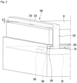
- FIG. 1 is a perspective view showing a bed in which a cleaner is installed according to a first embodiment of the present disclosure
- FIG. 2 is a view showing a state where the cleaner according to the first embodiment of the present disclosure has moved to a lower end of the bed
- FIG. 3 is a side view showing a bed in which a cleaner is installed according to the first embodiment of the present disclosure.
- a cleaner 100 for a bed (hereinafter, referred to as a "cleaner") according to the first embodiment of the present disclosure may be installed at a bed B.
- the bed B may include a lower frame F, a mattress M placed on the frame F, and a head portion H provided at an upper end of the frame F.
- the head portion H may extend from an upper side of the mattress M.
- the mattress M may have a rectangular parallelepiped shape having a predetermined vertical thickness.
- a portion where the head portion H is positioned may be defined as a "front portion” of the bed B and the opposite side may be defined as a “rear portion” of the bed B. Also between two positions, the position closer to the head portion H may be defined as a "front” and the position closer to the opposite side may be defined as a "rear”.
- the cleaner 100 may be configured to surround an upper surface and both side surfaces of the mattress M.
- the cleaner 100 may be positioned adjacent to the surface of the mattress M and may be provided to be movable in a longitudinal direction of the bed B.
- the bed B is formed with a guide groove 30 to guide a movement path of the cleaner 100.
- the guide groove 30 may be formed such that at least part of a lateral portion of the frame F is penetrated therethrough, and may extend in a longitudinal direction.
- the guide groove 30 is formed on both sides of the frame F.
- Both side portions of the cleaner 100 may be inserted into the guide groove 30 and move in the longitudinal direction in which the guide groove 30 extends.
- a rack 250 interworking with the cleaner 100 may be provided on an inner side of the guide groove 30.
- a transfer motor assembly 150 (see FIG. 7 ) of the cleaner 100 may work with the rack 250.
- the pinion gear 154 of the transfer motor assembly 150 is gear-coupled with the rack 250, and the cleaner 100 may be moved in a front-rear direction as the pinion gear 154 and the rack 250 interwork with each other.
- the cleaner 100 includes a cleaning body bent to surround the outer surface of the mattress M.
- An inner flow path 180 (see FIG. 10 ) through which dust sucked from the mattress M may flow may be formed in the cleaning body.
- the cleaning body includes a first part 110 disposed adjacent to the upper surface of the mattress M and a second part 120 extending downward from both sides of the first part 110 and disposed adjacent to side surfaces of the mattress M.
- a suction portion 113 capable of sucking foreign matter or dust present in the mattress M is formed on a bottom of the first part 110.
- a distance between the bottom of the first part 110 and the upper surface of the mattress M may be maintained at or below a set distance S1.
- the set distance S1 may be formed in the range of 2 to 5mm.
- the cleaning body further includes a third part 130 extending from the second part 120 toward an inner direction of the guide groove 30.
- the third part 130 may be inserted into the guide groove 30.
- the transfer motor assembly 150 may be installed at an upper portion of the third part 130 (see FIG. 7 ).
- the cleaning body may have a shape that is bent twice, for example, a cap shape or "C" shape.
- a support plate 50 on which some of the components of the cleaner 100 are installed may be provided on an inner side of the frame F.
- An installation height of the support plate 50 may be lower than an upper end of the frame F.
- a cleaning motor 160 for generating a suction force to the cleaner 100 and a dust box 165 for storing dust in the air flown in by the suction force of the cleaning motor 160 may be installed on the support plate 50.
- the cleaning motor 160 and the dust box 165 may be supported on an upper surface of the support plate 50.
- the cleaner 100 may be moved linearly in a front-rear direction of the bed B.
- the cleaner 100 may be positioned at a first position P1 adjacent to the rear side of the mattress M.
- the first position P1 may be a limit position at the rear of the cleaner 100.
- the cleaner 100 may move forward from the first position P1 and may be positioned at a second position P2.
- the second position P2 may be a reference center position in the front-rear direction of the cleaner 100.
- the cleaner 100 may move forward from the second position P2 and may be positioned at a third position P3.
- the third position P3 may be a position at which the cleaner 100 is inserted into the head portion H and may be a limit position at the front of the cleaner 100.
- the head portion H may be provided with insertion portions H1 and H2 into which the cleaner 100 may be inserted.
- the insertion portions H1 and H2 may be recessed forward from a rear surface of the head portion H.
- the insertion portions H1 and H2 may include a first insertion portion H1 and a second insertion portion H2 spaced apart in the longitudinal direction with respect to the head portion H.
- the first insertion portion H1 may be formed above the second insertion portion H2.
- the first part 110 of the cleaner 100 may be inserted into the first insertion portion H1 and the third part 130 of the cleaner 100 may be inserted into the second insertion portion H2.
- the cleaner 100 When the cleaner 100 is at the third position P3, the cleaner 100 has moved outside of the mattress M, and thus the user may use the mattress M without any inconvenience. That is, the third position P3 is a limit position of the cleaner 100 at which the cleaner 100 is inserted into the head portion H, and the cleaner 100 is at the third position P3 when not in use.
- the cleaner 100 may move from the third position P3 toward the first position P1 and clean the mattress M, while moving or reciprocating in the front-rear direction between the first position P1 and the third position P3.
- the cleaner 100 may include sensors 310 and 320 for detecting state information or use information of the mattress M.
- a bottom sensor 310 may detect a distance between the first part 110 and the upper surface of the mattress M.
- the bottom sensor 310 may be a distance sensor, for example, that may be an infrared sensor. As described above, the distance between the bottom surface of the first part 110 and the upper surface of the mattress M may need to be maintained within the set distance S1.
- a vertical height of the mattress M may vary for each manufacturer.
- the upper surface of the mattress M may be recessed downward.
- the distance between the upper surface of the mattress M and the bottom of the first part 110 may be detected using the bottom sensor 310 and a height of the first part 110 may be adjusted according to the detection result, that is, the distance between the first part 110 and the upper surface of the mattress M may be adjusted (see FIGS. 10 and 11 ).
- the sensors 310 and 320 may further include a front sensor 320 that may be provided on a front surface of the first part 110 to detect the presence of an object on the mattress M.
- the object may be, for example, a human body or a stuff.
- the front sensor 320 may be a distance sensor and may be configured as an infrared sensor, for example.
- the operation of the cleaner 100 may be stopped and an alarm sound may be activated.
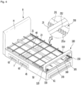
- FIG. 4 is a perspective view showing a state of a bed in which a cleaner is installed and a mattress is removed according to the first embodiment of the present disclosure
- FIG. 5 is an exploded perspective view showing a configuration of a bed in which a cleaner is installed according to the first embodiment of the present disclosure.
- the cleaner 100 may be installed at the bed B including a plurality of support frames 21 and 23 and brackets 40 and 45.
- the bed B includes the frame F with an open upper portion and the brackets 40 and 45 provided inside the frame F and supporting the mattress M.
- the brackets 40 and 45 may include a central bracket 40 positioned at the center of an inner space of the frame F and a lower bracket 45 positioned to be spaced apart in the front-rear direction in the inner space of the frame F.
- the lower bracket 45 may extend in a transverse direction.
- the central bracket 40 and the lower bracket 45 may be arranged to cross each other and coupled.
- the lower bracket 45 may be positioned below the support plate 50, and the central bracket 40 may extend upward through the support plate 50. That is, a part of the central bracket 40 may be disposed below the support plate 50 and the other part may be disposed above the support plate 50.
- the bed B may further include a plurality of support frames 21 and 23 positioned above the frame F and arranged in a grid shape.
- the plurality of support frames 21 and 23 may be positioned above the brackets 40 and 45 and may support the mattress M.
- the plurality of support frames 21 and 23 may include a plurality of main support frames 21 disposed to be spaced apart from each other in a transverse direction and extending in a front-rear direction and a plurality of sub-support frames 23 disposed to be spaced apart from each other in the front-rear direction and extending in the transverse direction.
- the plurality of sub-support frames 23 may be placed on the plurality of main support frames 21.
- a thickness and strength of the main support frame 21 may be greater than a thickness and strength of the sub-support frame 23.
- the main support frame 21 may be disposed at a height corresponding to a height of an upper end of the central bracket 40.
- the sub-support frame 23 may be placed in a frame recess 41 of the central bracket 40.
- the frame recess 41 may be a recess depressed from an upper surface of the central bracket 40.
- the rack 250 may be provided on both inner side surfaces of the frame F and may be disposed on both sides of the plurality of main support frame 21. In addition, the rack 250 may extend in the front-rear direction.
- the plurality of sub-support frames 23 may be placed on the rack 250.
- the rack 250 may include a rack body 251 extending in the front-rear direction.
- the rack body 251 may extend from the front end of the frame F to a rear end thereof.
- the rack 250 may further include a frame seating portion 252 formed on an upper surface of the rack body 251 and allow the sub-support frame 23 to be seated or inserted thereon.
- the rack 250 may include a gear portion 251a formed on a side surface of the rack body 251 and may include a plurality of gear teeth.
- the gear portion 251a may be linked to a pinion gear 154 of the transfer motor assembly 150 (see FIG. 7 ).
- a plurality of drawers 61, 63, and 65 may be provided to be drawn out in the frame F.
- the plurality of drawers 61, 63, and 65 may be disposed in an inner space of the frame F partitioned by the brackets 40 and 45.
- a plurality of drawer insertion holes 68 through which the plurality of drawers 61, 63, and 65 may be drawn may be formed in the frame F.
- the plurality of drawers 61, 63, and 65 may include a first drawer 61 provided to be drawn out at a rear portion of the frame F.
- the first drawer 61 may be provided to be drawn out backward, and a horizontal width of the first drawer 61 may be similar to a horizontal width of the frame F.
- the plurality of drawers 61, 63, and 65 may include second and third drawers 63 and 65 provided to be drawn out at side portions of the frame F.
- the second and third drawers 63 and 65 may be provided to be drawn out laterally, and the third drawer 65 may be disposed on the rear side of the second drawer 63.
- the support plate 50 may be disposed in a space between the brackets 40 and 45 and the plurality of support frames 21 and 23. That is, the support plate 50 may be disposed above the brackets 40 and 45 and below the plurality of support frames 21 and 23.
- the guide hole 30 of the frame F may be formed at a position higher than the support plate 50, and the third part 130 of the cleaner 100 may be inserted into the guide hole 30 and extend to the inner space of the frame F. Therefore, the third part 130 may be disposed at a position higher than the support plate 50.
- the cleaning motor 160 and the dust box 165 may be installed at the support plate 50, and the transfer motor assembly 150 may be seated on the upper surface of the third part 150.
- a dust flow path 170 provided at the cleaner 100 may be disposed in a space between the brackets 40 and 45 and the plurality of support frames 21 and 23.
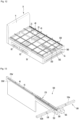
- FIG. 6 is a perspective view showing a configuration of a cleaner according to the first embodiment of the present disclosure
- FIG. 7 is a perspective view showing a configuration of a transfer motor assembly according to the first embodiment of the present disclosure
- FIG. 8 is a side view showing a configuration of a transfer motor assembly according to the first embodiment of the present disclosure
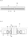
- FIG. 9 is a view showing a configuration of a bottom of a first part of a main body of a cleaner according to the first embodiment of the present disclosure.
- the cleaner 100 may include cleaning bodies 110, 120, and 130 provided to be movable in a front-rear direction and sucking dust or foreign matters, a cleaning motor 160 generating suction force, a dust box 165 communicating with the cleaning bodies 110, 120, and 130 and storing dust or foreign matter, and a dust flow path 170 connecting the cleaning bodies 110, 120, 130 and the dust box 165.
- the dust flow path 170 may be connected to the third part 130 of the cleaning body and extend to the dust box 165. That is, one end of the dust flow path 170 may be coupled to the third part 130, and the other end thereof may be coupled to the dust box 165.
- the dust flow path 170 may include a fixed flow path 171 coupled to the dust box 165 and extending in a transverse direction and a variable flow path 173 extending forward from both sides of the fixed flow path 171 and varied in length or shape.
- the dust flow path 170 may be formed of a corrugated pipe that may be deformed.
- the fixed flow path 171 and the variable flow path 173 may be integrally formed.
- the fixed flow path 171 may extend in the transverse direction through the central bracket 40 and may be coupled to the dust box 165.
- the central bracket 40 may have a flow path through a portion 42 through which the fixed flow path 171 is inserted.
- the fixed flow path 171 may include a first flow path portion connected to the first variable flow path 173a and a second flow path portion connected to the second variable flow path 173b among the two variable flow paths 173.
- the first flow path portion may be coupled to one side of the dust box 165, and the second flow path portion may be coupled to the other side of the dust box 165.
- Dust flowing through the first variable flow path 173a may be sucked into the dust box 165 through the first flow path portion, and dust flowing through the second variable flow path 173b may be sucked into the dust box 165 through the second flow path portion.
- the dust box 165 communicates with the cleaning motor 160, and air from which foreign matter is separated through the dust box 165 may be discharged to the outside via the cleaning motor 160.
- variable flow paths 173 that is, the first and second variable flow paths 173a and 173b, may be connected to two third parts 130, respectively.
- the variable flow path 173 may be folded and arranged in two stages. Specifically, at least part of the variable flow path 173 may be folded to form a folded portion 174.
- variable flow path 173 When the cleaner 100 moves in the front-rear direction, a position of the folded portion 174 moves in the front-rear direction, and in this process, the variable flow path 173 may be deformed. By the configuration and operation of the variable flow path 173, the dust sucked through the cleaner 100 may be easily sucked into the cleaning motor 160 even if the cleaner 100 is moved.
- the rack 250 may include a first rack 250a disposed on one side of the frame F and a second rack 250b disposed on the other side.
- the cleaner 100 may include two transfer motor assemblies 150 to correspond to the first and second racks 250a and 250b.
- the two transfer motor assemblies 150 may be installed on two third parts 130 of the cleaning body.
- the transfer motor assembly 150 may include a motor housing 151 provided on an upper surface of the third part 130, a transfer motor 152 installed in the motor housing 151, and a motor gear 153 coupled to the transfer motor 152.
- the motor gear 153 may be coupled to a motor shaft 152a of the transfer motor 152.
- the transfer motor assembly 150 may further include a pinion gear 154 interworking with the motor gear 153.
- the pinion gear 154 may be positioned outside the motor housing 151 and may be gear-coupled to the gear portion 251a of the rack 250.
- the pinion gear 154 may be coupled to the third part 130 through a gear support 155.
- the gear support 155 may extend upward from an upper surface of the third part 130 and may be coupled to the center of the pinion gear 154.
- the cleaning bodies 110, 120, and 130 may move in the front-rear direction as the rack 250 and the pinion gear 154 interwork with each other.
- the cleaning body may be referred to as a "dust pipe" in that it guides a flow of dust.
- the first part 110 may extend in a transverse direction and may be positioned adjacent to the upper surface of the mattress M.
- a suction portion 113 for sucking dust or foreign matter is formed on a bottom portion 111 of the first part 110, that is, a surface facing the upper surface of the mattress M.
- the suction portion 113 may be provided in plurality and may be arranged in a transverse direction. When the cleaning motor 160 is driven, a suction force acts on the suction portion 113, and foreign matter or dust existing in the mattress M may be sucked in.
- the first part 110 may be provided with an irradiation source 115 for removing harmful organisms or germs present in the mattress M.
- the irradiation source 115 may include an ultraviolet lamp.
- the irradiation source 115 may be provided in plurality on the bottom portion 111 and arranged in the transverse direction.
- a bottom sensor 310 may be installed on the bottom portion 111 of the first part 110.
- the bottom sensor 310 may detect a distance between the bottom portion 111 and the upper surface of the mattress M. When the detected distance is greater than or equal to the set distance, the first part 110 may be moved downward.
- the bottom sensor 310 may be provided in plurality, for example, at the central portion and both side portions of the bottom portion 111.
- a front sensor 320 for detecting whether a certain obstacle is present on the mattress M may be provided at a front portion 112 of the first part 110. When it is detected that an obstacle exists through the front sensor 320, movement of the cleaner 100 may be stopped and an alarm sound may be activated.
- the front sensor 320 may be provided in plurality, for example, at the central portion and both side portions of the front portion 112.
- FIG. 10 is a cross-sectional view taken along line X-X' of FIG. 6
- FIG. 11 is a cross-sectional view showing a state where the first part of the cleaner has moved upward with respect to a second part according to the first embodiment of the present disclosure.
- the cleaner 100 may further include the first part 110 provided to be movable in a longitudinal direction and the second part 120 extending downward from opposing sides of the first part 110.
- an upper portion of the second part 120 may be inserted into the first part 110.
- both sides of the first part 110 may be inserted into the second part 120.
- the cleaner 100 may further include a vertical motor 350 providing a driving force for vertical movement of the first part 110 and a slider 355 connected to the vertical motor 350 and pushing up the first part 110.
- the vertical motor 350 may be installed on a side portion of the second part 120, and the slider 355 may extend from the vertical motor 350 and may be coupled to the first part 110.
- the slider 355 may extend upward from the vertical motor 350 and may be coupled to a side surface of the first part 110.
- the vertical motor 350 and the slider 355 may be provided at the two second parts 120, respectively, and may be synchronized with each other to smoothly control the vertical movement of the first part 110.
- the vertical motor 350 When the distance between the upper surface of the mattress M and the bottom of the first part 110 is recognized to be the set distance S1 (See FIG. 2 ) or greater through the bottom sensor 310 provided at the bottom portion 111 of the first part 110, the vertical motor 350 may be driven and the slider 355 is drawn into the vertical motor 350 and the first part 110 may move downward.
- the vertical motor 350 may be driven and the slider 355 is drawn out from the vertical motor 350 so that the first part 110 may move upward.
- the suction portion 113 and the irradiation source 115 are formed at the bottom portion 111 of the first part 110.
- the suction portion 113 and the irradiation source 115 may be provided on an inner surface of the second part 120. Therefore, foreign matter present on the side surface of the mattress M may be sucked through the suction portion of the second part 120, and the side of the mattress M may be sterilized through the irradiation source of the second part 120.
- FIG. 12 is a perspective view showing a state of a bed in which a cleaner is installed and a mattress is removed according to a second example of the present disclosure, not according to the invention
- FIG. 13 is a perspective view showing a configuration of a cleaner according to a second example of the present disclosure
- FIG. 14 is a view showing a configuration of a bottom of a first part of a main body of the cleaner according to the second example of the present disclosure
- FIG. 15 is an internal perspective view showing a configuration of a transfer motor assembly according to the second example of the present disclosure
- FIG. 16 is a view showing a flow of sucked dust in the cleaner according to the second example of the present disclosure.
- a cleaner 500 according to the second example of the present disclosure not according to the invention may be installed at a bed B provided with a plurality of support frames 21 and 23 and brackets 40 and 45.
- the plurality of support frames 21 and 23 and the brackets 40 and 45 may be coupled to the frame F.
- the brackets 40 and 45 may include a central bracket 40 and a lower bracket 45.
- the description of the first embodiment may be used as description of the plurality of support frames 21 and 23 and the brackets 40 and 45.
- the bed B may include a first to third drawers 61, 63, and 65 provided to be retractable, and the description of the first embodiment may be used as description of the first to third drawers 61, 63, and 65.
- the bed B may include a support plate 50, and the support plate 50 may be disposed in a space between the brackets 40 and 45 and the plurality of support frames 21 and 23. That is, the support plate 50 may be disposed above the brackets 40 and 45 and below the plurality of support frames 21 and 23.
- the support plate 50 may be provided with a cleaning motor 560 and a dust box 565, a transfer motor assembly 550 may be coupled to the side of the central bracket 40.
- a dust flow path 570 provided in the cleaner 500 may be disposed in a space between the brackets 40 and 45 and the plurality of support frames 21 and 23.
- the cleaner 500 may include a cleaning body 510 provided to be movable in a front-rear direction and sucking dust or foreign matter, a cleaning motor 560 generating a suction force, a dust box 565 communicating with the cleaning body 510 and storing dust or foreign matter, and a dust flow path 565 connecting the cleaning body 510 and the dust box 565 to each other.
- the cleaning body 510 may be referred to as a "dust pipe" in that it guides a flow of dust.
- the cleaning body 510 may extend in the transverse direction and may be positioned adjacent to the bottom of the mattress M.
- the cleaning body 510 may include a first body 510a disposed on one side of the central bracket 40 and a second body 510b disposed on the other side.
- the first body 510a may be disposed on the right side of the central bracket 40 and the second body 510b may be disposed on the left side of the central bracket 40.
- the first and second bodies 510a and 510b may have the same configuration. Therefore, the first body 510a will be representatively described and the description thereof may be equally applicable to the second body 510b.
- the first body 510a may extend in a transverse direction and have a shape of a bar that sucks dust from the mattress M.
- the first body 510a has a frame insertion portion 518 on which the main support frame 21 may be placed.
- the frame insertion portion 518 may include a recess depressed downward from the upper surface portion 511 of the first body 510a.
- the upper surface portion 511 that is, the surface facing the bottom of the mattress M may be formed with a suction portion 513 for sucking dust or foreign matter.
- the suction portion 513 may be provided in plurality and may be arranged in a transverse direction. When the cleaning motor 560 is driven, a suction force acts on the suction portion 513 to suck foreign matter or dust present in the mattress M.
- the first body 510a may be provided with an irradiation source 515 for removing harmful organisms or germs present in the mattress M.
- the irradiation source 515 may include an ultraviolet lamp.
- the irradiation source 515 may be provided in plurality on the upper surface portion 511 and arranged in the transverse direction.
- the dust flow path 570 may extend from the first and second bodies 510a and 510b to the dust box 565.
- the dust flow path 570 may include a fixed flow path 571 coupled to the dust box 565 and extending in the transverse direction and a variable flow path 573 connected to the fixed flow path 571 and extending to the first and second bodies 510a and 510b.
- the variable flow path 573 may extend forward from each of the first and second bodies 510a and 510b and is configured to be variable in length or shape.
- the dust flow path 570 may be configured as a corrugated pipe that may be deformed.
- the fixed flow path 571 and the variable flow path 573 may be integrally formed.
- the variable flow path 573 may include a first variable flow path 573a extending forward from the first body 510a and having a folded portion 574 and a second variable flow path 573b extending forward from the second body 510b and having the folded portion 574.
- the first and second variable flow paths 573a and 573b may be folded at the folded portion 574 and arranged in two stages.
- the folded portion 574 may move in the front-rear direction, and in this process, the first and second variable flow paths 573a and 573b may be deformed.
- the variable flow path 573 By the configuration and operation of the variable flow path 573, dust sucked through the cleaner 500 may be easily sucked into the dust box 565 even if the cleaner 500 is moved.
- the fixed flow path 571 and the first and second variable flow paths 573a and 573b may be connected to each other.
- the first variable flow path 573a may join at a first junction 575a of the fixed flow path 571 and the second variable flow path 573b may join at a second junction 575b of the fixed flow path 571.
- suction force acts on the first and second bodies 510a and 510b and dust or foreign matter of the mattress M may be sucked into the first and second bodies 510a and 510b by the suction force.
- Dust or foreign matter sucked into the first and second bodies 510a and 510b flows through the first and second variable flow paths 573a and 573b, respectively, and flows into the fixed flow path 571 through the first and second joints 575a and 575b. Further, the dust or foreign matter flowed through the fixed flow path 571 is stored in the dust box 565, and air from which the dust or foreign matter is separated may be discharged to the outside via the cleaning motor 560.
- Racks 250a' and 250b' may be provided on opposing side surfaces of the central bracket 40.
- the racks 250a' and 250b' may include a first rack 250a' disposed on one side of the central bracket 40 and a second rack 250b' disposed on the other side of the central bracket 40.
- the cleaner 500 may include two transfer motor assemblies 550 corresponding to the first and second racks 250a' and 250b'.
- the two transfer motor assemblies 550 may be coupled to rear surfaces of the first and second bodies 510a and 510b, respectively.
- the transfer motor assembly 550 coupled to the first body 510a will be mainly described and the same description may be equally applicable to the transfer motor assembly 550 coupled to the second body 510b.
- the transfer motor assembly 550 may include a motor housing 551 provided on a rear surface of the first body 510a, a transfer motor 552 installed in the motor housing 551, and a motor gear 553 coupled to motor 552.
- the motor gear 553 may be coupled to a motor shaft 552a of the transfer motor 152.
- the transfer motor assembly 550 may further include a pinion gear 554 interworking with the motor gear 553. At least a portion of the pinion gear 554 may be positioned outside the motor housing 551 and may be gear-coupled to a gear portion 251a' of the rack 250a'.
- the pinion gear 554 may be coupled to the motor housing 551 through a gear support 555.
- the gear support 555 may extend upward from the bottom of the motor housing 551 and may be coupled to the center of the pinion gear 554.
- the cleaning bodies 510a and 510b may move in a front-rear direction as the first racks 250a' and 250b' interwork with the pinion gear 554.
- FIG. 17 is a perspective view showing a configuration of a cleaner according to a third embodiment of the present disclosure.
- a cleaner according to the third embodiment of the present disclosure may be configured by coupling the cleaning bodies 510a and 510b described in the second example and the cleaning body 600 described in the first embodiment.
- the transfer motor assembly 550 may be provided to move the cleaner according to the present embodiment, and a description thereof is the same as the description of the transfer motor assembly 550 of the second example.
- a cleaning motor 560, a dust box 565, and a dust flow path 570 may be provided to store dust sucked through the cleaning body in the dust box, and a description thereof is the same as the description of the transfer motor assembly 550 of the second example.
- a structure of the cleaning body 600 may be the same as a configuration of the cleaning bodies 110, 120, and 130 described in the first embodiment.
- the cleaning body 600 may include a first part 610, a second part 620, and a third part 630.
- the description of the first to third parts 610, 620, and 630 is the same as the description of the first to third parts 110, 120, and 130 of the first embodiment.
- the cleaning bodies 510a and 510b may be coupled to both sides of the cleaning body 600, that is, the two third parts 630.
- the first and second cleaning bodies 510a and 510b may be coupled to upper surfaces of the two third parts 630.
- the third part 630 may include a connection portion 650 connected to the first and second cleaning bodies 510a and 510b. Through the connection portion 650, the third part 630 and the first and second cleaning bodies 510a and 510b may communicate with each other.
- the connection portion 650 may be formed to penetrate through at least a portion of the upper surface of the third part 630.
- a hole connected to the connection portion 650 may be formed on the bottoms of the first and second cleaning bodies 510a and 510b. Therefore, when the cleaning motor 560 is driven, a suction force may act on the first and second cleaning bodies 510a and 510b and the cleaning body 600.
- the cleaning body 510a and 510b may be disposed adjacent to the bottom of the mattress M to suck dust or foreign matter, and the cleaning body 600 may be disposed adjacent to the upper surface of the mattress M to suck in dust or foreign matter. According to this configuration, there is an advantage that dust or foreign matter may be sucked from the bottom and the upper surface of the mattress M.
- the cleaning bodies 510a and 510b may be referred to as “lower cleaning bodies” and the cleaning body 600 may be referred to as an "upper cleaning body”.
- the cleaner for a bed since the cleaner is positioned adjacent to the surface of the bed mattress, cleaning efficiency of the mattress may be increased and the volume of the cleaner may be reduced.
- the cleaner may perform cleaning, while moving up and down with reference to the longitudinal direction of the mattress of the bed, it is possible to evenly clean the entire surface of the mattress.
- the dust suction port is provided on the bottom or upper surface of the cleaner, it is possible to easily suck dust present in the mattress.
- the irradiation source for irradiating ultraviolet rays is disposed at the cleaner, it is possible to easily remove the harmful germs.
- the cleaner is provided with the sensor for detecting an obstacle or the sensor for detecting a distance to the surface of the mattress, it is possible to easily adjust the height of the cleaner according to a detection result.
- the main body of the cleaner is provided on the upper or lower surface of the mattress, dust and the like present on the surface of the mattress may be easily removed.
- the dust flow path for guiding a flow of dust sucked into the cleaner is provided and the dust flow path includes the variable flow path varied in length or shape, dust may be easily sucked and flow even while the cleaner is moving.
- the transfer guide device for guiding movement of the cleaner Since the transfer guide device for guiding movement of the cleaner is provided, the cleaner may be smoothly moved.
Landscapes
- Engineering & Computer Science (AREA)
- Mechanical Engineering (AREA)
- Health & Medical Sciences (AREA)
- Epidemiology (AREA)
- Life Sciences & Earth Sciences (AREA)
- Animal Behavior & Ethology (AREA)
- General Health & Medical Sciences (AREA)
- Public Health (AREA)
- Veterinary Medicine (AREA)
- Nozzles For Electric Vacuum Cleaners (AREA)
- Cleaning In General (AREA)
Claims (8)
- Bettreiniger (100), wobei das Bett (B) einen Rahmen (F) umfasst, auf dem eine Matratze (M) auf dem Rahmen (F) angeordnet ist und eine Führungsnut (30) auf beiden Seiten des Rahmens ausgebildet ist, um eine Bewegung des Bettreinigers zu führen, wobei der Reiniger (100) aufweist:einen Reinigungskörper, der geeignet ist, in Bezug auf eine Oberfläche der Matratze (M) vorwärts oder rückwärts bewegt zu werden, wobei der Reinigungskörper einen Saugabschnitt (113) zum Saugen von Fremdstoffen von der Matratze (M) hat;einen Reinigungsmotor (160), um mit dem Reinigungskörper in Verbindung zu stehen und eine Saugkraft zu erzeugen,einen Staubbehälter (165), der mit dem Reinigungsmotor (160) verbunden ist, um durch den Saugabschnitt (113) gesaugte Fremdstoffe zu lagern;einen Übertragungsmotor (152), der auf einer Seite des Reinigungskörpers bereitgestellt ist, um eine Antriebskraft zum Bewegen des Reinigungskörpers zu erzeugen, undeinen Staubflussweg (170), der den Reinigungskörper und den Staubbehälter (165) verbindet,wobei der Staubflussweg (170) einen veränderbaren Flussweg (173) umfasst, dessen Form veränderbar ist, während der Reinigungskörper sich vorwärts oder rückwärts bewegt,wobei der Reinigungskörper aufweist:
einen ersten Teil (110), der sich in Bezug auf eine obere Oberfläche der Matratze (M) horizontal erstreckt; und wobei der Saugabschnitt (113) auf einem unteren Abschnitt (111) des ersten Teils (110) ausgebildet ist, der geeignet ist, der oberen Oberfläche der Matratze (M) zugewandt zu werden, dadurch gekennzeichnet, dass der Reinigungskörper ferner aufweist:einen zweiten Teil (120), der sich von beiden Seiten des ersten Teils (110) vertikal erstreckt, so dass er Seitenoberflächen der Matratze (M) zugewandt ist, undeinen dritten Teil (130), der sich von dem zweiten Teil (120) in Richtung einer Innenrichtung der Führungsnut (30) des Rahmens (F) erstreckt. - Bettreiniger (100) nach Anspruch 1, der ferner aufweist:einen vertikalen Motor (350), der an dem Reinigungskörper bereitgestellt ist, um eine Antriebskraft zum Bewegen des ersten Teils (110) nach oben oder nach unten bereitzustellen; undeinen Schieber (355), der mit dem vertikalen Motor und dem ersten Teil (110) verbunden ist.
- Bettreiniger (100) nach Anspruch 2, der ferner aufweist:einen unteren Sensor (310), der an einem unteren Abschnitt des ersten Teils (110) bereitgestellt ist, um einen Abstand zwischen der Matratze (M) und dem ersten Teil (110) abzutasten,wobei der vertikale Motor (350) basierend auf einem von dem unteren Sensor (310) abgetasteten Ergebnis angetrieben wird.
- Bettreiniger (100) nach einem der Ansprüche 1 bis 3, der ferner aufweist:einen vorderen Sensor (320), der auf einem vorderen Oberflächenabschnitt des ersten Teils (110) bereitgestellt ist, um abzutasten, ob an der Matratze (M) ein Gegenstand vorhanden ist,wobei der Übertragungsmotor (152) basierend auf einem von dem vorderen Sensor (320) abgetasteten Ergebnis angetrieben wird.
- Bettreiniger (100) nach einem der Ansprüche 1 bis 4, wobei eine Strahlungsquelle (115) zum Sterilisieren der Matratze (M) an einem unteren Abschnitt des ersten Teils (110) bereitgestellt ist.
- Bettreiniger (100) nach einem der Ansprüche 1 bis 5, wobeider veränderbare Flussweg (173) einen gefalteten Abschnitt (174) aufweist, undeine Position des gefalteten Abschnitts (174) sich ändert, wenn der Reinigungskörper sich vorwärts oder rückwärts bewegt.
- Bettreiniger (100) nach einem der Ansprüche 1 bis 6, der ferner aufweist:ein Ritzel (154), das mit dem Übertragungsmotor (152) verbunden ist, undeine Zahnstange (250), die mit dem Ritzel (154) zusammenwirkt.
- Bettreiniger (100) nach einem der Ansprüche 1 bis 7, wobeider Reinigungskörper ferner einen dritten Teil (130) aufweist, der sich von dem zweiten Teil (120) in Bezug auf den zweiten Teil (120) in eine Einwärtsrichtung erstreckt, undder Übertragungsmotor (152) an dem dritten Teil installiert ist.
Applications Claiming Priority (1)
| Application Number | Priority Date | Filing Date | Title |
|---|---|---|---|
| KR1020180154350A KR102621166B1 (ko) | 2018-12-04 | 2018-12-04 | 침대용 청소장치 |
Publications (2)
| Publication Number | Publication Date |
|---|---|
| EP3662802A1 EP3662802A1 (de) | 2020-06-10 |
| EP3662802B1 true EP3662802B1 (de) | 2023-08-09 |
Family
ID=68762559
Family Applications (1)
| Application Number | Title | Priority Date | Filing Date |
|---|---|---|---|
| EP19212815.5A Active EP3662802B1 (de) | 2018-12-04 | 2019-12-02 | Bettreiniger |
Country Status (4)
| Country | Link |
|---|---|
| US (1) | US11565008B2 (de) |
| EP (1) | EP3662802B1 (de) |
| KR (1) | KR102621166B1 (de) |
| CN (1) | CN111265145A (de) |
Families Citing this family (14)
| Publication number | Priority date | Publication date | Assignee | Title |
|---|---|---|---|---|
| USD955148S1 (en) * | 2019-07-25 | 2022-06-21 | Lg Electronics Inc. | Headboard for bed |
| USD959888S1 (en) * | 2019-07-25 | 2022-08-09 | Lg Electronics Inc. | Bed with sterilizing bar |
| USD957156S1 (en) * | 2019-12-23 | 2022-07-12 | Lg Electronics Inc. | Bed with mattress |
| USD957157S1 (en) * | 2019-12-23 | 2022-07-12 | Lg Electronics Inc. | Bed with mattress |
| KR102959805B1 (ko) * | 2021-01-14 | 2026-04-30 | 엘지전자 주식회사 | 매트리스 관리장치 |
| KR102858614B1 (ko) | 2021-01-14 | 2025-09-11 | 엘지전자 주식회사 | 매트리스 관리장치 |
| KR102956531B1 (ko) | 2021-01-14 | 2026-04-23 | 엘지전자 주식회사 | 매트리스 관리장치 |
| KR102956532B1 (ko) | 2021-01-14 | 2026-04-23 | 엘지전자 주식회사 | 매트리스 관리장치 |
| KR102959806B1 (ko) * | 2021-01-14 | 2026-04-30 | 엘지전자 주식회사 | 매트리스 관리장치 |
| KR102959804B1 (ko) | 2021-01-14 | 2026-04-30 | 엘지전자 주식회사 | 매트리스 관리장치 |
| KR102956530B1 (ko) | 2021-01-14 | 2026-04-24 | 엘지전자 주식회사 | 매트리스 관리장치 |
| KR102858613B1 (ko) | 2021-01-14 | 2025-09-12 | 엘지전자 주식회사 | 매트리스 관리장치 |
| JP7217044B2 (ja) * | 2021-01-28 | 2023-02-02 | 株式会社吉田製作所 | 自動シート消毒装置 |
| CN114343988B (zh) * | 2021-12-06 | 2023-12-19 | 江苏独角兽电子科技有限公司 | 一种高位截瘫患者医疗护理便捷清理辅助床 |
Citations (1)
| Publication number | Priority date | Publication date | Assignee | Title |
|---|---|---|---|---|
| US20050055792A1 (en) * | 2003-09-15 | 2005-03-17 | David Kisela | Autonomous vacuum cleaner |
Family Cites Families (16)
| Publication number | Priority date | Publication date | Assignee | Title |
|---|---|---|---|---|
| JP2002318071A (ja) * | 2001-04-18 | 2002-10-31 | Eco Net:Kk | 殺菌乾燥装置 |
| JP2006204571A (ja) * | 2005-01-28 | 2006-08-10 | Mitsubishi Heavy Ind Ltd | 寝具清浄装置 |
| KR100701914B1 (ko) * | 2005-03-03 | 2007-04-05 | 최영범 | 살균건조장치가 구비된 침대 |
| KR20090111632A (ko) | 2008-04-22 | 2009-10-27 | 김현우 | 침대 매트리스용 자외선 살균장치 |
| JP2010194122A (ja) | 2009-02-25 | 2010-09-09 | Sanyo Electric Co Ltd | 布団用電気掃除機 |
| US8519357B2 (en) * | 2009-10-22 | 2013-08-27 | Anthony Peter Noto | Cleaning apparatus for sanitizing furnishings |
| CN204861855U (zh) | 2015-06-19 | 2015-12-16 | 罗建光 | 一种自动清理床垫灰尘装置 |
| KR102453377B1 (ko) | 2015-10-30 | 2022-10-11 | 코웨이 주식회사 | 에어 매트리스를 포함하는 매트리스 어셈블리 |
| CN105747681A (zh) | 2016-03-09 | 2016-07-13 | 湖南工程学院 | 一种智能沙发 |
| CN205432965U (zh) * | 2016-03-23 | 2016-08-10 | 邓素婷 | 一种方便清扫床底的床 |
| KR101853624B1 (ko) | 2016-05-30 | 2018-05-17 | 주식회사 코렘 | 침대 살균 시스템 |
| CN106075493B (zh) | 2016-07-29 | 2019-06-18 | 王晓松 | 一种履带式智能床用除螨仪 |
| CN106175247B (zh) | 2016-08-29 | 2018-11-13 | 海宁汉林沙发有限公司 | 一种智能沙发 |
| CN207136647U (zh) | 2017-03-09 | 2018-03-27 | 北京南洋森林家具有限公司 | 床 |
| CN108354755A (zh) * | 2018-03-22 | 2018-08-03 | 周少华 | 一种神经内科检查用具有自动消毒功能的检查床 |
| CN108851735A (zh) * | 2018-09-08 | 2018-11-23 | 海宁舒友家具有限公司 | 一种便于清理底部灰尘的家用沙发 |
-
2018
- 2018-12-04 KR KR1020180154350A patent/KR102621166B1/ko active Active
-
2019
- 2019-11-11 US US16/679,849 patent/US11565008B2/en active Active
- 2019-12-02 CN CN201911213182.XA patent/CN111265145A/zh active Pending
- 2019-12-02 EP EP19212815.5A patent/EP3662802B1/de active Active
Patent Citations (1)
| Publication number | Priority date | Publication date | Assignee | Title |
|---|---|---|---|---|
| US20050055792A1 (en) * | 2003-09-15 | 2005-03-17 | David Kisela | Autonomous vacuum cleaner |
Also Published As
| Publication number | Publication date |
|---|---|
| CN111265145A (zh) | 2020-06-12 |
| EP3662802A1 (de) | 2020-06-10 |
| KR20200067464A (ko) | 2020-06-12 |
| US11565008B2 (en) | 2023-01-31 |
| US20200171183A1 (en) | 2020-06-04 |
| KR102621166B1 (ko) | 2024-01-05 |
Similar Documents
| Publication | Publication Date | Title |
|---|---|---|
| EP3662802A1 (de) | Bettreiniger | |
| AU2018222574B9 (en) | Robot cleaner | |
| GB2404330B (en) | Robot cleaner having floor-disinfecting function | |
| GB2413945A (en) | Robot vacuum cleaner and associated contaminant guide members | |
| CN103479296A (zh) | 具有杀菌底座的真空吸尘器 | |
| KR200457354Y1 (ko) | 다목적 uv램프모듈 및 이 uv램프모듈이 착탈가능하게 결합된 로봇청소기 | |
| US6295695B1 (en) | Vacuum cleaner | |
| US20220218118A1 (en) | Mattress care device | |
| CN104884882B (zh) | 适用于冷却装置门上的搁架 | |
| KR20070066673A (ko) | 자외선 살균 로봇청소기 | |
| KR102858614B1 (ko) | 매트리스 관리장치 | |
| KR102959805B1 (ko) | 매트리스 관리장치 | |
| CN103480015A (zh) | 具有紫外线引导装置的紫外线杀菌装置 | |
| KR102959804B1 (ko) | 매트리스 관리장치 | |
| KR102956531B1 (ko) | 매트리스 관리장치 | |
| USD1108750S1 (en) | Robotic vacuum cleaner | |
| KR20150005284A (ko) | 흡입구 막힘 방지 청소기 | |
| KR102959806B1 (ko) | 매트리스 관리장치 | |
| KR100518388B1 (ko) | 공기 청정 및 살균 기능을 갖는 침대 | |
| KR20080000950U (ko) | 상측 살균 기구를 가진 로봇 청소기 | |
| KR102172492B1 (ko) | 가습 공기청정기 | |
| KR20170030197A (ko) | 청소대상물의 표면에 대한 주행력이 확보된 청소기 | |
| KR20210038035A (ko) | 침대 청소기 | |
| KR101213185B1 (ko) | 진공청소기용 흡입장치 | |
| KR20210037152A (ko) | 침대 청소기 |
Legal Events
| Date | Code | Title | Description |
|---|---|---|---|
| PUAI | Public reference made under article 153(3) epc to a published international application that has entered the european phase |
Free format text: ORIGINAL CODE: 0009012 |
|
| STAA | Information on the status of an ep patent application or granted ep patent |
Free format text: STATUS: REQUEST FOR EXAMINATION WAS MADE |
|
| 17P | Request for examination filed |
Effective date: 20200102 |
|
| AK | Designated contracting states |
Kind code of ref document: A1 Designated state(s): AL AT BE BG CH CY CZ DE DK EE ES FI FR GB GR HR HU IE IS IT LI LT LU LV MC MK MT NL NO PL PT RO RS SE SI SK SM TR |
|
| AX | Request for extension of the european patent |
Extension state: BA ME |
|
| RBV | Designated contracting states (corrected) |
Designated state(s): AL AT BE BG CH CY CZ DE DK EE ES FI FR GB GR HR HU IE IS IT LI LT LU LV MC MK MT NL NO PL PT RO RS SE SI SK SM TR |
|
| STAA | Information on the status of an ep patent application or granted ep patent |
Free format text: STATUS: EXAMINATION IS IN PROGRESS |
|
| 17Q | First examination report despatched |
Effective date: 20200916 |
|
| GRAP | Despatch of communication of intention to grant a patent |
Free format text: ORIGINAL CODE: EPIDOSNIGR1 |
|
| STAA | Information on the status of an ep patent application or granted ep patent |
Free format text: STATUS: GRANT OF PATENT IS INTENDED |
|
| INTG | Intention to grant announced |
Effective date: 20230222 |
|
| GRAS | Grant fee paid |
Free format text: ORIGINAL CODE: EPIDOSNIGR3 |
|
| GRAA | (expected) grant |
Free format text: ORIGINAL CODE: 0009210 |
|
| STAA | Information on the status of an ep patent application or granted ep patent |
Free format text: STATUS: THE PATENT HAS BEEN GRANTED |
|
| AK | Designated contracting states |
Kind code of ref document: B1 Designated state(s): AL AT BE BG CH CY CZ DE DK EE ES FI FR GB GR HR HU IE IS IT LI LT LU LV MC MK MT NL NO PL PT RO RS SE SI SK SM TR |
|
| REG | Reference to a national code |
Ref country code: GB Ref legal event code: FG4D |
|
| REG | Reference to a national code |
Ref country code: CH Ref legal event code: EP |
|
| REG | Reference to a national code |
Ref country code: IE Ref legal event code: FG4D |
|
| REG | Reference to a national code |
Ref country code: DE Ref legal event code: R096 Ref document number: 602019034476 Country of ref document: DE |
|
| REG | Reference to a national code |
Ref country code: LT Ref legal event code: MG9D |
|
| REG | Reference to a national code |
Ref country code: NL Ref legal event code: MP Effective date: 20230809 |
|
| REG | Reference to a national code |
Ref country code: AT Ref legal event code: MK05 Ref document number: 1596493 Country of ref document: AT Kind code of ref document: T Effective date: 20230809 |
|
| PG25 | Lapsed in a contracting state [announced via postgrant information from national office to epo] |
Ref country code: GR Free format text: LAPSE BECAUSE OF FAILURE TO SUBMIT A TRANSLATION OF THE DESCRIPTION OR TO PAY THE FEE WITHIN THE PRESCRIBED TIME-LIMIT Effective date: 20231110 |
|
| PG25 | Lapsed in a contracting state [announced via postgrant information from national office to epo] |
Ref country code: IS Free format text: LAPSE BECAUSE OF FAILURE TO SUBMIT A TRANSLATION OF THE DESCRIPTION OR TO PAY THE FEE WITHIN THE PRESCRIBED TIME-LIMIT Effective date: 20231209 |
|
| PG25 | Lapsed in a contracting state [announced via postgrant information from national office to epo] |
Ref country code: SE Free format text: LAPSE BECAUSE OF FAILURE TO SUBMIT A TRANSLATION OF THE DESCRIPTION OR TO PAY THE FEE WITHIN THE PRESCRIBED TIME-LIMIT Effective date: 20230809 Ref country code: RS Free format text: LAPSE BECAUSE OF FAILURE TO SUBMIT A TRANSLATION OF THE DESCRIPTION OR TO PAY THE FEE WITHIN THE PRESCRIBED TIME-LIMIT Effective date: 20230809 Ref country code: PT Free format text: LAPSE BECAUSE OF FAILURE TO SUBMIT A TRANSLATION OF THE DESCRIPTION OR TO PAY THE FEE WITHIN THE PRESCRIBED TIME-LIMIT Effective date: 20231211 Ref country code: NO Free format text: LAPSE BECAUSE OF FAILURE TO SUBMIT A TRANSLATION OF THE DESCRIPTION OR TO PAY THE FEE WITHIN THE PRESCRIBED TIME-LIMIT Effective date: 20231109 Ref country code: NL Free format text: LAPSE BECAUSE OF FAILURE TO SUBMIT A TRANSLATION OF THE DESCRIPTION OR TO PAY THE FEE WITHIN THE PRESCRIBED TIME-LIMIT Effective date: 20230809 Ref country code: LV Free format text: LAPSE BECAUSE OF FAILURE TO SUBMIT A TRANSLATION OF THE DESCRIPTION OR TO PAY THE FEE WITHIN THE PRESCRIBED TIME-LIMIT Effective date: 20230809 Ref country code: LT Free format text: LAPSE BECAUSE OF FAILURE TO SUBMIT A TRANSLATION OF THE DESCRIPTION OR TO PAY THE FEE WITHIN THE PRESCRIBED TIME-LIMIT Effective date: 20230809 Ref country code: IS Free format text: LAPSE BECAUSE OF FAILURE TO SUBMIT A TRANSLATION OF THE DESCRIPTION OR TO PAY THE FEE WITHIN THE PRESCRIBED TIME-LIMIT Effective date: 20231209 Ref country code: HR Free format text: LAPSE BECAUSE OF FAILURE TO SUBMIT A TRANSLATION OF THE DESCRIPTION OR TO PAY THE FEE WITHIN THE PRESCRIBED TIME-LIMIT Effective date: 20230809 Ref country code: GR Free format text: LAPSE BECAUSE OF FAILURE TO SUBMIT A TRANSLATION OF THE DESCRIPTION OR TO PAY THE FEE WITHIN THE PRESCRIBED TIME-LIMIT Effective date: 20231110 Ref country code: FI Free format text: LAPSE BECAUSE OF FAILURE TO SUBMIT A TRANSLATION OF THE DESCRIPTION OR TO PAY THE FEE WITHIN THE PRESCRIBED TIME-LIMIT Effective date: 20230809 Ref country code: AT Free format text: LAPSE BECAUSE OF FAILURE TO SUBMIT A TRANSLATION OF THE DESCRIPTION OR TO PAY THE FEE WITHIN THE PRESCRIBED TIME-LIMIT Effective date: 20230809 |
|
| PG25 | Lapsed in a contracting state [announced via postgrant information from national office to epo] |
Ref country code: PL Free format text: LAPSE BECAUSE OF FAILURE TO SUBMIT A TRANSLATION OF THE DESCRIPTION OR TO PAY THE FEE WITHIN THE PRESCRIBED TIME-LIMIT Effective date: 20230809 |
|
| PG25 | Lapsed in a contracting state [announced via postgrant information from national office to epo] |
Ref country code: ES Free format text: LAPSE BECAUSE OF FAILURE TO SUBMIT A TRANSLATION OF THE DESCRIPTION OR TO PAY THE FEE WITHIN THE PRESCRIBED TIME-LIMIT Effective date: 20230809 |
|
| PG25 | Lapsed in a contracting state [announced via postgrant information from national office to epo] |
Ref country code: SM Free format text: LAPSE BECAUSE OF FAILURE TO SUBMIT A TRANSLATION OF THE DESCRIPTION OR TO PAY THE FEE WITHIN THE PRESCRIBED TIME-LIMIT Effective date: 20230809 Ref country code: RO Free format text: LAPSE BECAUSE OF FAILURE TO SUBMIT A TRANSLATION OF THE DESCRIPTION OR TO PAY THE FEE WITHIN THE PRESCRIBED TIME-LIMIT Effective date: 20230809 Ref country code: ES Free format text: LAPSE BECAUSE OF FAILURE TO SUBMIT A TRANSLATION OF THE DESCRIPTION OR TO PAY THE FEE WITHIN THE PRESCRIBED TIME-LIMIT Effective date: 20230809 Ref country code: EE Free format text: LAPSE BECAUSE OF FAILURE TO SUBMIT A TRANSLATION OF THE DESCRIPTION OR TO PAY THE FEE WITHIN THE PRESCRIBED TIME-LIMIT Effective date: 20230809 Ref country code: DK Free format text: LAPSE BECAUSE OF FAILURE TO SUBMIT A TRANSLATION OF THE DESCRIPTION OR TO PAY THE FEE WITHIN THE PRESCRIBED TIME-LIMIT Effective date: 20230809 Ref country code: CZ Free format text: LAPSE BECAUSE OF FAILURE TO SUBMIT A TRANSLATION OF THE DESCRIPTION OR TO PAY THE FEE WITHIN THE PRESCRIBED TIME-LIMIT Effective date: 20230809 Ref country code: SK Free format text: LAPSE BECAUSE OF FAILURE TO SUBMIT A TRANSLATION OF THE DESCRIPTION OR TO PAY THE FEE WITHIN THE PRESCRIBED TIME-LIMIT Effective date: 20230809 |
|
| REG | Reference to a national code |
Ref country code: DE Ref legal event code: R097 Ref document number: 602019034476 Country of ref document: DE |
|
| PG25 | Lapsed in a contracting state [announced via postgrant information from national office to epo] |
Ref country code: IT Free format text: LAPSE BECAUSE OF FAILURE TO SUBMIT A TRANSLATION OF THE DESCRIPTION OR TO PAY THE FEE WITHIN THE PRESCRIBED TIME-LIMIT Effective date: 20230809 |
|
| PLBE | No opposition filed within time limit |
Free format text: ORIGINAL CODE: 0009261 |
|
| STAA | Information on the status of an ep patent application or granted ep patent |
Free format text: STATUS: NO OPPOSITION FILED WITHIN TIME LIMIT |
|
| 26N | No opposition filed |
Effective date: 20240513 |
|
| PG25 | Lapsed in a contracting state [announced via postgrant information from national office to epo] |
Ref country code: SI Free format text: LAPSE BECAUSE OF FAILURE TO SUBMIT A TRANSLATION OF THE DESCRIPTION OR TO PAY THE FEE WITHIN THE PRESCRIBED TIME-LIMIT Effective date: 20230809 |
|
| REG | Reference to a national code |
Ref country code: CH Ref legal event code: PL |
|
| PG25 | Lapsed in a contracting state [announced via postgrant information from national office to epo] |
Ref country code: LU Free format text: LAPSE BECAUSE OF NON-PAYMENT OF DUE FEES Effective date: 20231202 |
|
| PG25 | Lapsed in a contracting state [announced via postgrant information from national office to epo] |
Ref country code: MC Free format text: LAPSE BECAUSE OF FAILURE TO SUBMIT A TRANSLATION OF THE DESCRIPTION OR TO PAY THE FEE WITHIN THE PRESCRIBED TIME-LIMIT Effective date: 20230809 |
|
| GBPC | Gb: european patent ceased through non-payment of renewal fee |
Effective date: 20231202 |
|
| REG | Reference to a national code |
Ref country code: BE Ref legal event code: MM Effective date: 20231231 |
|
| PG25 | Lapsed in a contracting state [announced via postgrant information from national office to epo] |
Ref country code: MC Free format text: LAPSE BECAUSE OF FAILURE TO SUBMIT A TRANSLATION OF THE DESCRIPTION OR TO PAY THE FEE WITHIN THE PRESCRIBED TIME-LIMIT Effective date: 20230809 Ref country code: LU Free format text: LAPSE BECAUSE OF NON-PAYMENT OF DUE FEES Effective date: 20231202 |
|
| REG | Reference to a national code |
Ref country code: IE Ref legal event code: MM4A |
|
| PG25 | Lapsed in a contracting state [announced via postgrant information from national office to epo] |
Ref country code: IE Free format text: LAPSE BECAUSE OF NON-PAYMENT OF DUE FEES Effective date: 20231202 |
|
| PG25 | Lapsed in a contracting state [announced via postgrant information from national office to epo] |
Ref country code: GB Free format text: LAPSE BECAUSE OF NON-PAYMENT OF DUE FEES Effective date: 20231202 |
|
| PG25 | Lapsed in a contracting state [announced via postgrant information from national office to epo] |
Ref country code: BE Free format text: LAPSE BECAUSE OF NON-PAYMENT OF DUE FEES Effective date: 20231231 |
|
| PG25 | Lapsed in a contracting state [announced via postgrant information from national office to epo] |
Ref country code: FR Free format text: LAPSE BECAUSE OF NON-PAYMENT OF DUE FEES Effective date: 20231231 |
|
| PG25 | Lapsed in a contracting state [announced via postgrant information from national office to epo] |
Ref country code: CH Free format text: LAPSE BECAUSE OF NON-PAYMENT OF DUE FEES Effective date: 20231231 |
|
| PG25 | Lapsed in a contracting state [announced via postgrant information from national office to epo] |
Ref country code: IE Free format text: LAPSE BECAUSE OF NON-PAYMENT OF DUE FEES Effective date: 20231202 Ref country code: GB Free format text: LAPSE BECAUSE OF NON-PAYMENT OF DUE FEES Effective date: 20231202 Ref country code: FR Free format text: LAPSE BECAUSE OF NON-PAYMENT OF DUE FEES Effective date: 20231231 Ref country code: CH Free format text: LAPSE BECAUSE OF NON-PAYMENT OF DUE FEES Effective date: 20231231 Ref country code: BE Free format text: LAPSE BECAUSE OF NON-PAYMENT OF DUE FEES Effective date: 20231231 |
|
| PG25 | Lapsed in a contracting state [announced via postgrant information from national office to epo] |
Ref country code: BG Free format text: LAPSE BECAUSE OF FAILURE TO SUBMIT A TRANSLATION OF THE DESCRIPTION OR TO PAY THE FEE WITHIN THE PRESCRIBED TIME-LIMIT Effective date: 20230809 |
|
| PG25 | Lapsed in a contracting state [announced via postgrant information from national office to epo] |
Ref country code: BG Free format text: LAPSE BECAUSE OF FAILURE TO SUBMIT A TRANSLATION OF THE DESCRIPTION OR TO PAY THE FEE WITHIN THE PRESCRIBED TIME-LIMIT Effective date: 20230809 |
|
| PG25 | Lapsed in a contracting state [announced via postgrant information from national office to epo] |
Ref country code: CY Free format text: LAPSE BECAUSE OF FAILURE TO SUBMIT A TRANSLATION OF THE DESCRIPTION OR TO PAY THE FEE WITHIN THE PRESCRIBED TIME-LIMIT; INVALID AB INITIO Effective date: 20191202 |
|
| PG25 | Lapsed in a contracting state [announced via postgrant information from national office to epo] |
Ref country code: HU Free format text: LAPSE BECAUSE OF FAILURE TO SUBMIT A TRANSLATION OF THE DESCRIPTION OR TO PAY THE FEE WITHIN THE PRESCRIBED TIME-LIMIT; INVALID AB INITIO Effective date: 20191202 |
|
| PG25 | Lapsed in a contracting state [announced via postgrant information from national office to epo] |
Ref country code: TR Free format text: LAPSE BECAUSE OF FAILURE TO SUBMIT A TRANSLATION OF THE DESCRIPTION OR TO PAY THE FEE WITHIN THE PRESCRIBED TIME-LIMIT Effective date: 20230809 |
|
| PGFP | Annual fee paid to national office [announced via postgrant information from national office to epo] |
Ref country code: DE Payment date: 20251105 Year of fee payment: 7 |