EP3662714B1 - Gestion de ressource dans un système de communication sans fil - Google Patents
Gestion de ressource dans un système de communication sans fil Download PDFInfo
- Publication number
- EP3662714B1 EP3662714B1 EP18852741.0A EP18852741A EP3662714B1 EP 3662714 B1 EP3662714 B1 EP 3662714B1 EP 18852741 A EP18852741 A EP 18852741A EP 3662714 B1 EP3662714 B1 EP 3662714B1
- Authority
- EP
- European Patent Office
- Prior art keywords
- scell
- grant
- assignment
- deactivation timer
- mac pdu
- Prior art date
- Legal status (The legal status is an assumption and is not a legal conclusion. Google has not performed a legal analysis and makes no representation as to the accuracy of the status listed.)
- Active
Links
- 238000004891 communication Methods 0.000 title claims description 65
- 230000009849 deactivation Effects 0.000 claims description 49
- 238000000034 method Methods 0.000 claims description 37
- 230000005540 biological transmission Effects 0.000 description 71
- 230000006870 function Effects 0.000 description 29
- 238000012546 transfer Methods 0.000 description 19
- 230000004913 activation Effects 0.000 description 16
- 238000010586 diagram Methods 0.000 description 14
- 230000000875 corresponding effect Effects 0.000 description 13
- 238000005516 engineering process Methods 0.000 description 13
- 238000007726 management method Methods 0.000 description 12
- 230000015654 memory Effects 0.000 description 11
- 238000001514 detection method Methods 0.000 description 10
- 230000008569 process Effects 0.000 description 9
- 230000009471 action Effects 0.000 description 8
- 238000012544 monitoring process Methods 0.000 description 7
- 230000011664 signaling Effects 0.000 description 7
- 239000000872 buffer Substances 0.000 description 6
- 238000013507 mapping Methods 0.000 description 6
- 238000010295 mobile communication Methods 0.000 description 6
- 241000700159 Rattus Species 0.000 description 5
- 230000002776 aggregation Effects 0.000 description 5
- 238000004220 aggregation Methods 0.000 description 5
- 238000012545 processing Methods 0.000 description 5
- 238000012937 correction Methods 0.000 description 4
- 230000003213 activating effect Effects 0.000 description 3
- 230000006835 compression Effects 0.000 description 3
- 238000007906 compression Methods 0.000 description 3
- 238000011161 development Methods 0.000 description 3
- 230000018109 developmental process Effects 0.000 description 3
- 230000007774 longterm Effects 0.000 description 3
- 230000000737 periodic effect Effects 0.000 description 3
- 238000012384 transportation and delivery Methods 0.000 description 3
- 101000741965 Homo sapiens Inactive tyrosine-protein kinase PRAG1 Proteins 0.000 description 2
- 102100038659 Inactive tyrosine-protein kinase PRAG1 Human genes 0.000 description 2
- 230000006978 adaptation Effects 0.000 description 2
- 230000008901 benefit Effects 0.000 description 2
- 230000020411 cell activation Effects 0.000 description 2
- 230000008859 change Effects 0.000 description 2
- 230000001276 controlling effect Effects 0.000 description 2
- 125000004122 cyclic group Chemical group 0.000 description 2
- 230000006837 decompression Effects 0.000 description 2
- 230000009977 dual effect Effects 0.000 description 2
- 230000000694 effects Effects 0.000 description 2
- 238000012423 maintenance Methods 0.000 description 2
- 238000005259 measurement Methods 0.000 description 2
- 230000004048 modification Effects 0.000 description 2
- 238000012986 modification Methods 0.000 description 2
- 238000012913 prioritisation Methods 0.000 description 2
- 238000011084 recovery Methods 0.000 description 2
- 230000004044 response Effects 0.000 description 2
- 230000011218 segmentation Effects 0.000 description 2
- 241000760358 Enodes Species 0.000 description 1
- 108700026140 MAC combination Proteins 0.000 description 1
- 238000003491 array Methods 0.000 description 1
- 239000000969 carrier Substances 0.000 description 1
- 238000006243 chemical reaction Methods 0.000 description 1
- 238000005352 clarification Methods 0.000 description 1
- 239000002131 composite material Substances 0.000 description 1
- 238000013461 design Methods 0.000 description 1
- 230000006866 deterioration Effects 0.000 description 1
- 238000005265 energy consumption Methods 0.000 description 1
- 230000007613 environmental effect Effects 0.000 description 1
- 239000002360 explosive Substances 0.000 description 1
- 238000001914 filtration Methods 0.000 description 1
- 238000007689 inspection Methods 0.000 description 1
- 230000003287 optical effect Effects 0.000 description 1
- 238000005457 optimization Methods 0.000 description 1
- 230000009467 reduction Effects 0.000 description 1
- 238000013468 resource allocation Methods 0.000 description 1
- 230000002441 reversible effect Effects 0.000 description 1
- 238000001228 spectrum Methods 0.000 description 1
- 230000001360 synchronised effect Effects 0.000 description 1
- 230000008685 targeting Effects 0.000 description 1
- 230000007704 transition Effects 0.000 description 1
Images


Classifications
-
- H—ELECTRICITY
- H04—ELECTRIC COMMUNICATION TECHNIQUE
- H04W—WIRELESS COMMUNICATION NETWORKS
- H04W72/00—Local resource management
- H04W72/02—Selection of wireless resources by user or terminal
-
- H—ELECTRICITY
- H04—ELECTRIC COMMUNICATION TECHNIQUE
- H04W—WIRELESS COMMUNICATION NETWORKS
- H04W72/00—Local resource management
- H04W72/12—Wireless traffic scheduling
- H04W72/1263—Mapping of traffic onto schedule, e.g. scheduled allocation or multiplexing of flows
-
- H—ELECTRICITY
- H04—ELECTRIC COMMUNICATION TECHNIQUE
- H04W—WIRELESS COMMUNICATION NETWORKS
- H04W76/00—Connection management
- H04W76/30—Connection release
- H04W76/38—Connection release triggered by timers
-
- H—ELECTRICITY
- H04—ELECTRIC COMMUNICATION TECHNIQUE
- H04W—WIRELESS COMMUNICATION NETWORKS
- H04W72/00—Local resource management
- H04W72/20—Control channels or signalling for resource management
- H04W72/23—Control channels or signalling for resource management in the downlink direction of a wireless link, i.e. towards a terminal
-
- H—ELECTRICITY
- H04—ELECTRIC COMMUNICATION TECHNIQUE
- H04L—TRANSMISSION OF DIGITAL INFORMATION, e.g. TELEGRAPHIC COMMUNICATION
- H04L5/00—Arrangements affording multiple use of the transmission path
- H04L5/0091—Signaling for the administration of the divided path
- H04L5/0096—Indication of changes in allocation
- H04L5/0098—Signalling of the activation or deactivation of component carriers, subcarriers or frequency bands
-
- H—ELECTRICITY
- H04—ELECTRIC COMMUNICATION TECHNIQUE
- H04W—WIRELESS COMMUNICATION NETWORKS
- H04W72/00—Local resource management
- H04W72/20—Control channels or signalling for resource management
Definitions
- the present disclosure relates to a wireless communication system.
- a method for transmitting/receiving signals effectively in a system supporting new radio access technology is required.
- WO 2015/139768 A1 generally relates to a method of restarting a deactivation timer.
- a mobile station activates a SCell for the mobile station, starts a deactivation timer associated with the SCell, receives data from a base station via the SCell and sends, to the base station, an acknowledgment, ACK, of the data received via the SCell. Then, the mobile station restarts the deactivation timer associated with the SCell based on sending the ACK and deactivates the SCell upon expiration of the deactivation timer.
- EP 3 110 193 A1 relates to a method including receiving use right control information that is of an activated secondary component carrier and sent by a base station and determining an available time of the activated secondary component carrier according to the use right control information; performing an operation related to the activated secondary component carrier within the available time; and stopping performing the operation related to the activated secondary component carrier after the available time is reached.
- US 2013/010641 A1 discloses that a base station transmits a RRC reconfiguration message to a RRC-connected wireless device to configure secondary carrier(s).
- the RRC reconfiguration message is configured to cause the RRC-connected wireless device to control the activation of at least one secondary carrier.
- the base station transmits data packets to the RRC-connected wireless device on a data channel on at least one of the secondary carriers.
- a wireless device receives a downlink control information (DCI) on a primary cell.
- the DCI may comprise a field instructing a wireless device to activate a secondary cell.
- the wireless device activates the secondary cell in response to receiving the DCI.
- implementations of the present disclosure may provide one or more of the following advantages.
- radio communication signals can be more efficiently transmitted and/or received. Therefore, overall throughput of a radio communication system can be improved.
- delay/latency occurring during communication between a user equipment and a BS may be reduced.
- signals in a new radio access technology system can be transmitted and/or received more effectively.
- a collection of "cells” is typically implemented to manage radio resources in different geographic regions.
- a cell typically provides downlink (DL) and/or uplink (UL) transmission services to a plurality of user equipment (UE) devices.
- DL downlink
- UL uplink
- Different types of cells may be implemented, such as a primary cell (Pcell) operating on a primary frequency, and a secondary cell (Scell) operating on a secondary frequency.
- Pcell primary cell
- Scell secondary cell
- a Scell may be configured after completion of connection establishment and may be used to provide additional radio resources in the wireless network.
- the wireless network may activate and deactivate the configured SCells.
- the UE and the wireless network maintain a timer referred to as the sCellDeactivationTimer for a configured SCell.
- the associated SCell is then configured to be deactivated upon expiry of the timer sCellDeactivationTimer.
- the sCellDeactivationTimer timer may be maintained at a Medium Access Control (MAC) entity in the UE and in the network.
- MAC Medium Access Control
- a problem occurs in that a UE may be configured to restart the timer sCellDeactivationTimer associated with an SCell merely based on an indication that there is an uplink grant or or downlink assignment for the activated SCell.
- the UE restarts the timer sCellDeactivationTimer associated with the SCell irrespective of whether a data unit (e.g., a MAC PDU) is actually available to be transmitted or received on the given uplink grant or downlink assignment, respectively.
- a data unit e.g., a MAC PDU
- a UE is configured to restart the timer sCellDeactivationTimer of a SCell when the UE actually transmits a MAC PDU by using an uplink grant or when the UE receives a MAC PDU using a downlink assignment.
- the UE is configured to restart the sCellDeactivationTimer for the SCell only when the UE actually transmits or receives a MAC PDU by using the uplink grant or downlink assignment.
- the UE does not restart the sCellDeactivationTimer for the SCell if the UE does not transmit or receive a MAC PDU by using the uplink grant or downlink assignment.
- a UE does not necessarily restart the sCellDeactivationTimer for an SCell merely based on detecting an uplink grant or a downlink assignment, but instead restarts the timer based on detecting that a transmission/reception of a data unit actually occurs on the uplink grant or downlink assignment.
- LTE 3rd Generation Partnership Project Long Term Evolution
- FIG. 1 is a diagram illustrating an example of a network structure of an E-UMTS as an exemplary radio communication system.
- An Evolved Universal Mobile Telecommunications System (E-UMTS) is an advanced version of a Universal Mobile Telecommunications System (UMTS) and basic standardization thereof is currently underway in the 3GPP.
- E-UMTS may be generally referred to as a Long Term Evolution (LTE) system.
- LTE Long Term Evolution
- the E-UMTS includes a User Equipment (UE), eNode Bs (eNBs), and an Access Gateway (AG) which is located at an end of the network (E-UTRAN) and connected to an external network.
- the eNBs may simultaneously transmit multiple data streams for a broadcast service, a multicast service, and/or a unicast service.
- One or more cells may exist per eNB.
- the cell is set to operate in one of bandwidths such as 1.25, 2.5, 5, 10, 15, and 20 MHz and provides a downlink (DL) or uplink (UL) transmission service to a plurality of UEs in the bandwidth. Different cells may be set to provide different bandwidths.
- the eNB controls data transmission or reception to and from a plurality of UEs.
- the eNB transmits DL scheduling information of DL data to a corresponding UE so as to inform the UE of a time/frequency domain in which the DL data is supposed to be transmitted, coding, a data size, and hybrid automatic repeat and request (HARQ)-related information.
- HARQ hybrid automatic repeat and request
- the eNB transmits UL scheduling information of UL data to a corresponding UE so as to inform the UE of a time/frequency domain which may be used by the UE, coding, a data size, and HARQ-related information.
- An interface for transmitting user traffic or control traffic may be used between eNBs.
- a core network (CN) may include the AG and a network node or the like for user registration of UEs.
- the AG manages the mobility of a UE on a tracking area (TA) basis.
- One TA includes a plurality of cells.
- WCDMA wideband code division multiple access
- next-generation RAT which takes into account such advanced mobile broadband communication, massive MTC (mMCT), and ultra-reliable and low latency communication (URLLC), is being discussed.
- CDMA code division multiple access
- FDMA frequency division multiple access
- TDMA time division multiple access
- OFDMA orthogonal frequency division multiple access
- SC-FDMA single carrier frequency division multiple access
- MC-FDMA multicarrier frequency division multiple access
- CDMA may be embodied through radio technology such as universal terrestrial radio access (UTRA) or CDMA2000.
- TDMA may be embodied through radio technology such as global system for mobile communications (GSM), general packet radio service (GPRS), or enhanced data rates for GSM evolution (EDGE).
- GSM global system for mobile communications
- GPRS general packet radio service
- EDGE enhanced data rates for GSM evolution
- OFDMA may be embodied through radio technology such as institute of electrical and electronics engineers (IEEE) 802.11 (Wi-Fi), IEEE 802.16 (WiMAX), IEEE 802.20, or evolved UTRA (E-UTRA).
- UTRA is a part of a universal mobile telecommunications system (UMTS).
- 3rd generation partnership project (3GPP) long term evolution (LTE) is a part of evolved UMTS (E-UMTS) using E-UTRA.
- 3GPP LTE employs OFDMA in DL and SC-FDMA in UL.
- LTE-advanced (LTE-A) is an evolved version of 3GPP LTE.
- LTE-A LTE-advanced
- the present disclosure is applicable to contention based communication such as Wi-Fi as well as non-contention based communication as in the 3GPP based system in which a BS allocates a DL/UL time/frequency resource to a UE and the UE receives a DL signal and transmits a UL signal according to resource allocation of the BS.
- a non-contention based communication scheme an access point (AP) or a control node for controlling the AP allocates a resource for communication between the UE and the AP, whereas, in a contention based communication scheme, a communication resource is occupied through contention between UEs which desire to access the AP.
- AP access point
- a contention based communication scheme will now be described in brief.
- CSMA carrier sense multiple access
- CSMA refers to a probabilistic media access control (MAC) protocol for confirming, before a node or a communication device transmits traffic on a shared transmission medium (also called a shared channel) such as a frequency band, that there is no other traffic on the same shared transmission medium.
- MAC media access control
- a transmitting device determines whether another transmission is being performed before attempting to transmit traffic to a receiving device. In other words, the transmitting device attempts to detect presence of a carrier from another transmitting device before attempting to perform transmission. Upon sensing the carrier, the transmitting device waits for another transmission device which is performing transmission to finish transmission, before performing transmission thereof.
- CSMA can be a communication scheme based on the principle of "sense before transmit” or “listen before talk".
- a scheme for avoiding collision between transmitting devices in the contention based communication system using CSMA includes carrier sense multiple access with collision detection (CSMA/CD) and/or carrier sense multiple access with collision avoidance (CSMA/CA).
- CSMA/CD is a collision detection scheme in a wired local area network (LAN) environment.
- a personal computer (PC) or a server which desires to perform communication in an Ethernet environment first confirms whether communication occurs on a network and, if another device carries data on the network, the PC or the server waits and then transmits data. That is, when two or more users (e.g.
- CSMA/CD is a scheme for flexibly transmitting data by monitoring collision.
- a transmitting device using CSMA/CD adjusts data transmission thereof by sensing data transmission performed by another device using a specific rule.
- CSMA/CA is a MAC protocol specified in IEEE 802.11 standards.
- a wireless LAN (WLAN) system conforming to IEEE 802.11 standards does not use CSMA/CD which has been used in IEEE 802.3 standards and uses CA, i.e. a collision avoidance scheme.
- Transmission devices always sense carrier of a network and, if the network is empty, the transmission devices wait for determined time according to locations thereof registered in a list and then transmit data.
- Various methods are used to determine priority of the transmission devices in the list and to reconfigure priority.
- collision may occur and, in this case, a collision sensing procedure is performed.
- a transmission device using CSMA/CA avoids collision between data transmission thereof and data transmission of another transmission device using a specific rule.
- a user equipment may be a fixed or mobile device.
- the UE include various devices that transmit and receive user data and/or various kinds of control information to and from a base station (BS).
- the UE may be referred to as a terminal equipment (TE), a mobile station (MS), a mobile terminal (MT), a user terminal (UT), a subscriber station (SS), a wireless device, a personal digital assistant (PDA), a wireless modem, a handheld device, etc.
- a BS generally refers to a fixed station that performs communication with a UE and/or another BS, and exchanges various kinds of data and control information with the UE and another BS.
- the BS may be referred to as an advanced base station (ABS), a node-B (NB), an evolved node-B (eNB), a base transceiver system (BTS), an access point (AP), a processing server (PS), etc.
- ABS advanced base station
- NB node-B
- eNB evolved node-B
- BTS base transceiver system
- AP access point
- PS processing server
- a BS of the UMTS is referred to as a NB
- a BS of the EPC/LTE is referred to as an eNB
- a BS of the new radio (NR) system is referred to as a gNB.
- a node refers to a fixed point capable of transmitting/ receiving a radio signal through communication with a UE.
- Various types of BSs may be used as nodes irrespective of the terms thereof.
- a BS a node B (NB), an e-node B (eNB), a pico-cell eNB (PeNB), a home eNB (HeNB), a relay, a repeater, etc.
- the node may not be a BS.
- the node may be a radio remote head (RRH) or a radio remote unit (RRU).
- the RRH or RRU generally has a lower power level than a power level of a BS.
- RRH/RRU Since the RRH or RRU (hereinafter, RRH/RRU) is generally connected to the BS through a dedicated line such as an optical cable, cooperative communication between RRH/RRU and the BS can be smoothly performed in comparison with cooperative communication between BSs connected by a radio line.
- At least one antenna is installed per node.
- the antenna may include a physical antenna or an antenna port or a virtual antenna.
- a cell refers to a prescribed geographical area to which one or more nodes provide a communication service. Accordingly, in the present disclosure, communicating with a specific cell may include communicating with a BS or a node which provides a communication service to the specific cell.
- a DL/UL signal of a specific cell refers to a DL/UL signal from/to a BS or a node which provides a communication service to the specific cell.
- a node providing UL/DL communication services to a UE is called a serving node and a cell to which UL/DL communication services are provided by the serving node is especially called a serving cell.
- a 3GPP based system implements a cell to manage radio resources and a cell associated with the radio resources is distinguished from a cell of a geographic region.
- a "cell” of a geographic region may be understood as coverage within which a node can provide service using a carrier and a "cell" of a radio resource is associated with bandwidth (BW) which is a frequency range configured by the carrier. Since DL coverage, which is a range within which the node is capable of transmitting a valid signal, and UL coverage, which is a range within which the node is capable of receiving the valid signal from the UE, depends upon a carrier carrying the signal, the coverage of the node may be associated with coverage of the "cell" of a radio resource used by the node. Accordingly, the term "cell" may be used to indicate service coverage of the node sometimes, a radio resource at other times, or a range that a signal using a radio resource can reach with valid strength at other times.
- the recent 3GPP based wireless communication standard implements a cell to manage radio resources.
- the "cell" associated with the radio resources utilizes a combination of downlink resources and uplink resources, for example, a combination of DL component carrier (CC) and UL CC.
- the cell may be configured by downlink resources only, or may be configured by downlink resources and uplink resources.
- linkage between a carrier frequency of the downlink resources (or DL CC) and a carrier frequency of the uplink resources (or UL CC) may be indicated by system information.
- SIB2 system information block type 2
- the carrier frequency may be a center frequency of each cell or CC.
- a cell operating on a primary frequency may be referred to as a primary cell (Pcell) or PCC
- a cell operating on a secondary frequency may be referred to as a secondary cell (Scell) or SCC.
- the carrier corresponding to the Pcell on downlink will be referred to as a downlink primary CC (DL PCC)
- the carrier corresponding to the Pcell on uplink will be referred to as an uplink primary CC (UL PCC).
- a Scell refers to a cell that may be configured after completion of radio resource control (RRC) connection establishment and used to provide additional radio resources.
- RRC radio resource control
- the Scell may form a set of serving cells for the UE together with the Pcell in accordance with capabilities of the UE.
- the carrier corresponding to the Scell on the downlink will be referred to as downlink secondary CC (DL SCC), and the carrier corresponding to the Scell on the uplink will be referred to as uplink secondary CC (UL SCC).
- DL SCC downlink secondary CC
- UL SCC uplink secondary CC
- the UE is in RRC-CONNECTED state, if it is not configured by carrier aggregation or does not support carrier aggregation, a single serving cell configured by the Pcell only exists.
- the network may activate and deactivate the configured SCells.
- the special cell (SpCell) is always activated.
- the network activates and deactivates the SCell(s) by sending the Activation/Deactivation MAC control element (CE) described.
- CE Activation/Deactivation MAC control element
- the MAC entity at each of the UE and the network maintains a timer referred to as the sCellDeactivationTimer per configured SCell (except the SCell configured with PUCCH, if any) and deactivates the associated SCell upon expiry of the timer.
- the same initial timer value applies to each instance of the sCellDeactivationTimer and the initial timer value is configured by RRC.
- the configured SCells are initially deactivated upon addition and after a handover.
- the configured secondary cell group (SCG) SCells are initially deactivated after a SCG change. For each TTI and for each configured SCell, the following logical flow applies:
- the MAC entity shall not transmit SRS on the SCell; not report CQI/PMI/RI/PTI/CRI for the SCell; not transmit on uplink shared channel (UL-SCH) on the SCell; not transmit on RACH on the SCell; not monitor the PDCCH on the SCell; not monitor the PDCCH for the SCell; not transmit PUCCH on the SCell.
- UL-SCH uplink shared channel
- the SCell Activation/Deactivation timing in the LTE system is as follows.
- the corresponding actions in MAC shall be applied no later than the minimum requirement defined in 3GPP TS 36.133 and no earlier than subframe n+8, except for the following: the actions related to CSI reporting on a serving cell which is active in subframe n+8, the actions related to the sCellDeactivationTimer associated with the SCell, and the actions related to CSI reporting on a serving cell which is not active in subframe n+8.
- the actions related to CSI reporting on a serving cell which is active in subframe n+8 and the actions related to the sCellDeactivationTimer associated with the SCell shall be applied in subframe n+8.
- the actions related to CSI reporting on a serving cell which is not active in subframe n+8 shall be applied in the earliest subframe after n+8 in which the serving cell is active.
- the corresponding actions in MAC shall apply no later than the minimum requirement defined in 3GPP TS 36.133, except for the actions related to CSI reporting on a serving cell which is active.
- the actions related to CSI reporting on a serving cell which is active shall be applied in subframe n+8.
- PDCCH refers to a PDCCH, an EPDCCH (in subframes when configured), a MTC PDCCH (MPDCCH), for an RN with R-PDCCH configured and not suspended, to the R-PDCCH or, for NB-IoT to the narrowband PDCCH (NPDCCH).
- MPDCCH MTC PDCCH
- NPDCCH narrowband PDCCH
- monitoring a channel refers to attempting to decode the channel.
- monitoring a PDCCH refers to attempting to decode PDCCH(s) (or PDCCH candidates).
- the term "special Cell” refers to the PCell of the master cell group (MCG) or the PSCell of the secondary cell group (SCG), and otherwise the term Special Cell refers to the PCell.
- the MCG is a group of serving cells associated with a master BS which terminates at least S1-MME
- the SCG is a group of serving cells associated with a secondary BS that is providing additional radio resources for the UE but is not the master BS.
- the SCG includes a primary SCell (PSCell) and optionally one or more SCells.
- PSCell primary SCell
- two MAC entities are configured in the UE: one for the MCG and one for the SCG.
- Each MAC entity is configured by RRC with a serving cell supporting PUCCH transmission and contention based Random Access.
- the term SpCell refers to such cell, whereas the term SCell refers to other serving cells.
- the term SpCell either refers to the PCell of the MCG or the PSCell of the SCG depending on if the MAC entity is associated to the MCG or the SCG, respectively.
- C-RNTI refers to a cell RNTI
- SI-RNTI refers to a system information RNTI
- P-RNTI refers to a paging RNTI
- RA-RNTI refers to a random access RNTI
- SC-RNTI refers to a single cell RNTI
- SL-RNTI refers to a sidelink RNTI
- SPS C-RNTI refers to a semi-persistent scheduling C-RNTI.
- 3GPP LTE/LTE-A standard documents for example, 3GPP TS 36.211, 3GPP TS 36.212, 3GPP TS 36.213, 3GPP TS 36.300, 3GPP TS 36.321, 3GPP TS 36.322, 3GPP TS 36.323 and 3GPP TS 36.331
- 3GPP NR standard documents for example, 3GPP TS 38.211, 3GPP TS 38.213, 3GPP TS 38.214, 3GPP TS 38.300, 3GPP TS 38.321, 3GPP TS 38.322, 3GPP TS 38.323 and 3GPP TS 38.331 may be referenced.
- FIG. 2 is a block diagram illustrating an example of an evolved universal terrestrial radio access network (E-UTRAN).
- E-UTRAN evolved universal terrestrial radio access network
- the E-UMTS may be also referred to as an LTE system.
- the communication network is widely deployed to provide a variety of communication services such as voice (VoIP) through IMS and packet data.
- VoIP voice
- IMS packet data
- the E-UMTS network includes an evolved UMTS terrestrial radio access network (E-UTRAN), an Evolved Packet Core (EPC) and one or more user equipment.
- the E-UTRAN may include one or more evolved NodeB (eNodeB) 20, and a plurality of user equipments (UE) 10 may be located in one cell.
- eNodeB evolved NodeB
- UE user equipments
- One or more E-UTRAN mobility management entity (MME)/system architecture evolution (SAE) gateways 30 may be positioned at the end of the network and connected to an external network.
- MME mobility management entity
- downlink refers to communication from BS 20 to UE 10
- uplink refers to communication from the UE to a BS.
- FIG. 3 is a block diagram depicting an example of an architecture of a typical E-UTRAN and a typical EPC.
- an eNB 20 provides end points of a user plane and a control plane to the UE 10.
- MME/SAE gateway 30 provides an end point of a session and mobility management function for UE 10.
- the eNB and MME/SAE gateway may be connected via an S1 interface.
- the eNB 20 is generally a fixed station that communicates with a UE 10, and may also be referred to as a base station (BS) or an access point.
- BS base station
- One eNB 20 may be deployed per cell.
- An interface for transmitting user traffic or control traffic may be used between eNBs 20.
- the MME provides various functions including NAS signaling to eNBs 20, NAS signaling security, access stratum (AS) Security control, Inter CN node signaling for mobility between 3GPP access networks, Idle mode UE Reachability (including control and execution of paging retransmission), Tracking Area list management (for UE in idle and active mode), PDN GW and Serving GW selection, MME selection for handovers with MME change, SGSN selection for handovers to 2G or 3G 3GPP access networks, roaming, authentication, bearer management functions including dedicated bearer establishment, support for PWS (which includes ETWS and CMAS) message transmission.
- the SAE gateway host provides assorted functions including Per-user based packet filtering (by e.g.
- MME/SAE gateway 30 will be referred to herein simply as a "gateway,” but it is understood that this entity includes both an MME and an SAE gateway.
- a plurality of nodes may be connected between eNB 20 and gateway 30 via the S1 interface.
- the eNBs 20 may be connected to each other via an X2 interface and neighboring eNBs may have a meshed network structure that has the X2 interface.
- eNB 20 may perform functions of selection for gateway 30, routing toward the gateway during a Radio Resource Control (RRC) activation, scheduling and transmitting of paging messages, scheduling and transmitting of Broadcast Channel (BCCH) information, dynamic allocation of resources to UEs 10 in both uplink and downlink, configuration and provisioning of eNB measurements, radio bearer control, radio admission control (RAC), and connection mobility control in LTE_ACTIVE state.
- gateway 30 may perform functions of paging origination, LTE-IDLE state management, ciphering of the user plane, System Architecture Evolution (SAE) bearer control, and ciphering and integrity protection of Non-Access Stratum (NAS) signaling.
- SAE System Architecture Evolution
- NAS Non-Access Stratum
- the EPC includes a mobility management entity (MME), a serving-gateway (S-GW), and a packet data network-gateway (PDN-GW).
- MME mobility management entity
- S-GW serving-gateway
- PDN-GW packet data network-gateway
- FIG. 4 is a diagram showing an example of a control plane and a user plane of a radio interface protocol between a UE and an E-UTRAN based on a 3GPP radio access network standard.
- the control plane refers to a path used for transmitting control messages used for managing a call between the UE and the E-UTRAN.
- the user plane refers to a path used for transmitting data generated in an application layer, e.g., voice data or Internet packet data.
- Layer 1 (i.e. L1) of the 3GPP LTE/LTE-A system is corresponding to a physical layer.
- a physical (PHY) layer of a first layer (Layer 1 or L1) provides an information transfer service to a higher layer using a physical channel.
- the PHY layer is connected to a medium access control (MAC) layer located on the higher layer via a transport channel. Data is transported between the MAC layer and the PHY layer via the transport channel. Data is transported between a physical layer of a transmitting side and a physical layer of a receiving side via physical channels.
- the physical channels use time and frequency as radio resources.
- the physical channel is modulated using an orthogonal frequency division multiple access (OFDMA) scheme in downlink and is modulated using a single carrier frequency division multiple access (SC-FDMA) scheme in uplink.
- OFDMA orthogonal frequency division multiple access
- SC-FDMA single carrier frequency division multiple access
- Layer 2 (i.e. L2) of the 3GPP LTE/LTE-A system is split into the following sublayers: Medium Access Control (MAC), Radio Link Control (RLC) and Packet Data Convergence Protocol (PDCP).
- the MAC layer of a second layer (Layer 2 or L2) provides a service to a radio link control (RLC) layer of a higher layer via a logical channel.
- the RLC layer of the second layer supports reliable data transmission.
- a function of the RLC layer may be implemented by a functional block of the MAC layer.
- a packet data convergence protocol (PDCP) layer of the second layer performs a header compression function to reduce unnecessary control information for efficient transmission of an Internet protocol (IP) packet such as an IP version 4 (IPv4) packet or an IP version 6 (IPv6) packet in a radio interface having a relatively small bandwidth.
- IP Internet protocol
- the main services and functions of the MAC sublayer include: mapping between logical channels and transport channels; multiplexing/demultiplexing of MAC SDUs belonging to one or different logical channels into/from transport blocks (TB) delivered to/from the physical layer on transport channels; scheduling information reporting; error correction through HARQ; priority handling between logical channels of one UE; priority handling between UEs by dynamic scheduling; MBMS service identification; transport format selection; and padding.
- the main services and functions of the RLC sublayer include: transfer of upper layer protocol data units (PDUs); error correction through ARQ (only for acknowledged mode (AM) data transfer); concatenation, segmentation and reassembly of RLC service data units (SDUs) (only for unacknowledged mode (UM) and acknowledged mode (AM) data transfer); re-segmentation of RLC data PDUs (only for AM data transfer); reordering of RLC data PDUs (only for UM and AM data transfer); duplicate detection (only for UM and AM data transfer); protocol error detection (only for AM data transfer); RLC SDU discard (only for UM and AM data transfer); and RLC re-establishment, except for a NB-IoT UE that only uses Control Plane CloT EPS optimizations.
- PDUs protocol data units
- ARQ only for acknowledged mode (AM) data transfer
- SDUs concatenation, segmentation and reassembly of RLC service data units
- SDUs
- the main services and functions of the PDCP sublayer for the user plane include: header compression and decompression (ROHC only); transfer of user data; in-sequence delivery of upper layer PDUs at PDCP re-establishment procedure for RLC AM; for split bearers in DC and LWA bearers (only support for RLC AM), PDCP PDU routing for transmission and PDCP PDU reordering for reception; duplicate detection of lower layer SDUs at PDCP re-establishment procedure for RLC AM; retransmission of PDCP SDUs at handover and, for split bearers in DC and LWA bearers, of PDCP PDUs at PDCP data-recovery procedure, for RLC AM; ciphering and deciphering; timer-based SDU discard in uplink.
- ROHC only header compression and decompression
- transfer of user data in-sequence delivery of upper layer PDUs at PDCP re-establishment procedure for RLC AM
- the main services and functions of the PDCP for the control plane include: ciphering and integrity protection; and transfer of control plane data.
- PDCP supports routing and reordering.
- the PDCP entity uses the reordering function when the PDCP entity is associated with two AM RLC entities, when the PDCP entity is configured for a LWA bearer; or when the PDCP entity is associated with one AM RLC entity after it was, according to the most recent reconfiguration, associated with two AM RLC entities or configured for a LWA bearer without performing PDCP re-establishment.
- Layer 3 of the LTE/LTE-A system includes the following sublayers: Radio Resource Control (RRC) and Non Access Stratum (NAS).
- RRC Radio Resource Control
- NAS Non Access Stratum
- a radio resource control (RRC) layer located at the bottom of a third layer is defined only in the control plane.
- the RRC layer controls logical channels, transport channels, and physical channels in relation to configuration, re-configuration, and release of radio bearers (RBs).
- An RB refers to a service that the second layer provides for data transmission between the UE and the E-UTRAN.
- the RRC layer of the UE and the RRC layer of the E-UTRAN exchange RRC messages with each other.
- the non-access stratum (NAS) layer positioned over the RRC layer performs functions such as session management and mobility management.
- Radio bearers are roughly classified into (user) data radio bearers (DRBs) and signaling radio bearers (SRBs). SRBs are defined as radio bearers (RBs) that are used only for the transmission of RRC and NAS messages.
- DRBs data radio bearers
- SRBs signaling radio bearers
- one cell of the eNB is set to operate in one of bandwidths such as 1.25, 2.5, 5, 10, 15, and 20 MHz and provides a downlink or uplink transmission service to a plurality of UEs in the bandwidth.
- bandwidths such as 1.25, 2.5, 5, 10, 15, and 20 MHz
- Different cells may be set to provide different bandwidths.
- Downlink transport channels for transmission of data from the E-UTRAN to the UE include a broadcast channel (BCH) for transmission of system information, a paging channel (PCH) for transmission of paging messages, and a downlink shared channel (SCH) for transmission of user traffic or control messages.
- BCH broadcast channel
- PCH paging channel
- SCH downlink shared channel
- Traffic or control messages of a downlink multicast or broadcast service may be transmitted through the downlink SCH and may also be transmitted through a separate downlink multicast channel (MCH).
- MCH downlink multicast channel
- Uplink transport channels for transmission of data from the UE to the E-UTRAN include a random access channel (RACH) for transmission of initial control messages and an uplink SCH for transmission of user traffic or control messages.
- Logical channels that are defined above the transport channels and mapped to the transport channels include a broadcast control channel (BCCH), a paging control channel (PCCH), a common control channel (CCCH), a multicast control channel (MCCH), and a multicast traffic channel (MTCH).
- BCCH broadcast control channel
- PCCH paging control channel
- CCCH common control channel
- MCCH multicast control channel
- MTCH multicast traffic channel
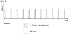
- FIG. 5 is a diagram showing an example of a physical channel structure used in an E-UMTS system.
- a physical channel includes several subframes on a time axis and several subcarriers on a frequency axis.
- one subframe includes a plurality of symbols on the time axis.
- One subframe includes a plurality of resource blocks and one resource block includes a plurality of symbols and a plurality of subcarriers.
- each subframe may use certain subcarriers of certain symbols (e.g., a first symbol) of a subframe for a physical downlink control channel (PDCCH), that is, an L1/L2 control channel.
- the PDCCH carries scheduling assignments and other control information.
- PDCCH physical downlink control channel
- an L1/L2 control information transmission area (PDCCH) and a data area (PDSCH) are shown.
- a radio frame of 10ms is used and one radio frame includes 10 subframes.
- one subframe includes two consecutive slots. The length of one slot may be 0.5ms.
- one subframe includes a plurality of OFDM symbols and a portion (e.g., a first symbol) of the plurality of OFDM symbols may be used for transmitting the L1/L2 control information.
- a time interval in which one subframe is transmitted is defined as a transmission time interval (TTI).
- Time resources may be distinguished by a radio frame number (or radio frame index), a subframe number (or subframe index), a slot number (or slot index), and the like.
- TTI refers to an interval during which data may be scheduled. For example, in the 3GPP LTE/LTE-A system, an opportunity of transmission of an UL grant or a DL grant is present every 1 ms, and the UL/DL grant opportunity does not exists several times in less than 1 ms. Therefore, the TTI in the legacy 3GPP LTE/ LTE-A system is 1ms.
- a base station and a UE mostly transmit/receive data via a PDSCH, which is a physical channel, using a downlink shared channel (DL-SCH) which is a transmission channel, except a certain control signal or certain service data.
- DL-SCH downlink shared channel
- a certain PDCCH is CRC-masked with a radio network temporary identity (RNTI) "A" and information about data is transmitted using a radio resource "B" (e.g., a frequency location) and transmission format information "C" (e.g., a transmission block size, modulation, coding information or the like) via a certain subframe.
- RNTI radio network temporary identity
- C transmission format information
- one or more UEs located in a cell monitor the PDCCH using its RNTI information.
- a specific UE with RNTI "A” reads the PDCCH and then receives the PDSCH indicated by B and C in the PDCCH information.
- a PDCCH addressed to an RNTI refers to the PDCCH being cyclic redundancy check masked (CRC-masked) with the RNTI.
- CRC-masked cyclic redundancy check masked
- a fully mobile and connected society is expected in the near future, which will be characterized by a tremendous amount of growth in connectivity, traffic volume and a much broader range of usage scenarios. Some typical trends include explosive growth of data traffic, great increase of connected devices and continuous emergence of new services. Besides the market requirements, the mobile communication society itself also requires a sustainable development of the eco-system, which produces the needs to further improve system efficiencies, such as spectrum efficiency, energy efficiency, operational efficiency and cost efficiency. To meet the above ever-increasing requirements from market and mobile communication society, next generation access technologies are expected to emerge in the near future.
- 5G New Radio is expected to expand and support diverse use case scenarios and applications that will continue beyond the current IMT-Advanced standard, for instance, enhanced Mobile Broadband (eMBB), Ultra Reliable Low Latency Communication (URLLC) and massive Machine Type Communication (mMTC).
- eMBB enhanced Mobile Broadband
- URLLC Ultra Reliable Low Latency Communication
- mMTC massive Machine Type Communication
- eMBB is targeting high data rate mobile broadband services, such as seamless data access both indoors and outdoors, and AR/VR applications;
- URLLC is defined for applications that have stringent latency and reliability requirements, such as vehicular communications that can enable autonomous driving and control network in industrial plants;
- mMTC is the basis for connectivity in IoT, which allows for infrastructure management, environmental monitoring, and healthcare applications.
- FIG. 6 illustrates an example of protocol stacks of a next generation wireless communication system.
- FIG. 6(a) illustrates an example of a radio interface user plane protocol stack between a UE and a gNB
- FIG. 6(b) illustrates an example of a radio interface control plane protocol stack between a UE and a gNB.
- the control plane refers to a path through which control messages used to manage call by a UE and a network are transported.
- the user plane refers to a path through which data generated in an application layer, for example, voice data or Internet packet data are transported.
- the user plane protocol stack may be divided into a first layer (Layer 1) (i.e., a physical layer (PHY) layer) and a second layer (Layer 2).
- Layer 1 i.e., a physical layer (PHY) layer
- Layer 2 a second layer
- the control plane protocol stack may be divided into Layer 1 (i.e., a PHY layer), Layer 2, Layer 3 (e.g., a radio resource control (RRC) layer), and a non-access stratum (NAS) layer.
- Layer 1 i.e., a PHY layer
- Layer 2 e.g., a radio resource control (RRC) layer
- NAS non-access stratum
- the overall protocol stack architecture for the NR system might be similar to that of the LTE/LTE-A system, but some functionalities of the protocol stacks of the LTE/ LTE-A system should be modified in the NR system in order to resolve the weakness or drawback of LTE.
- RAN WG2 for NR is in charge of the radio interface architecture and protocols.
- the new functionalities of the control plane include the following: on-demand system information delivery to reduce energy consumption and mitigate interference, two-level (i.e. Radio Resource Control (RRC) and Medium Access Control (MAC)) mobility to implement seamless handover, beam based mobility management to accommodate high frequency, RRC inactive state to reduce state transition latency and improve UE battery life.
- RRC Radio Resource Control
- MAC Medium Access Control
- the new functionalities of the user plane aim at latency reduction by optimizing existing functionalities, such as concatenation and reordering relocation, and RLC out of order delivery.
- SDAP Service Data Adaptation Protocol
- QoS Quality of Service
- RAN a new user plane AS protocol layer named as Service Data Adaptation Protocol (SDAP) has been introduced to handle flow-based Quality of Service (QoS) framework in RAN, such as mapping between QoS flow and a data radio bearer, and QoS flow ID marking.
- QoS Quality of Service
- the layer 2 of NR is split into the following sublayers: Medium Access Control (MAC), Radio Link Control (RLC), Packet Data Convergence Protocol (PDCP) and Service Data Adaptation Protocol (SDAP).
- MAC Medium Access Control
- RLC Radio Link Control
- PDCP Packet Data Convergence Protocol
- SDAP Service Data Adaptation Protocol
- the physical layer offers to the MAC sublayer transport channels, the MAC sublayer offers to the RLC sublayer logical channels, the RLC sublayer offers to the PDCP sublayer RLC channels, the PDCP sublayer offers to the SDAP sublayer radio bearers, and the SDAP sublayer offers to 5GC QoS flows.
- Radio bearers are categorized into two groups: data radio bearers (DRB) for user plane data and signalling radio bearers (SRB) for control plane data.
- DRB data radio bearers
- SRB signalling radio bearers
- the main services and functions of the MAC sublayer of NR include: mapping between logical channels and transport channels; multiplexing/demultiplexing of MAC SDUs belonging to one or different logical channels into/from transport blocks (TB) delivered to/from the physical layer on transport channels; scheduling information reporting; error correction through HARQ (one HARQ entity per carrier in case of carrier aggregation); priority handling between UEs by dynamic scheduling; priority handling between logical channels of one UE by logical channel prioritization; and padding.
- a single MAC entity can support one or multiple numerologies and/or transmission timings, and mapping restrictions in logical channel prioritisation controls which numerology and/or transmission timing a logical channel can use.
- the RLC sublayer of NR supports three transmission modes: Transparent Mode (TM); Unacknowledged Mode (UM); Acknowledged Mode (AM).
- TM Transparent Mode
- UM Unacknowledged Mode
- AM Acknowledged Mode
- the RLC configuration is per logical channel with no dependency on numerologies and/or TTI durations, and ARQ can operate on any of the numerologies and/or TTI durations the logical channel is configured with.
- SRB0 paging and broadcast system information
- TM mode is used for other SRBs.
- AM mode used for DRBs.
- DRBs either UM or AM mode are used.
- the main services and functions of the RLC sublayer depend on the transmission mode and include: transfer of upper layer PDUs; sequence numbering independent of the one in PDCP (UM and AM); error correction through ARQ (AM only); segmentation (AM and UM) and re-segmentation (AM only) of RLC SDUs; Reassembly of SDU (AM and UM); duplicate detection (AM only); RLC SDU discard (AM and UM); RLC re-establishment; and protocol error detection (AM only).
- the ARQ within the RLC sublayer of NR has the following characteristics: ARQ retransmits RLC PDUs or RLC PDU segments based on RLC status reports; polling for RLC status report is used when needed by RLC; and RLC receiver can also trigger RLC status report after detecting a missing RLC PDU or RLC PDU segment.
- the main services and functions of the PDCP sublayer of NR for the user plane include: sequence numbering; header compression and decompression (ROHC only); transfer of user data; reordering and duplicate detection; PDCP PDU routing (in case of split bearers); retransmission of PDCP SDUs; ciphering, deciphering and integrity protection; PDCP SDU discard; PDCP re-establishment and data recovery for RLC AM; and duplication of PDCP PDUs.
- the main services and functions of the PDCP sublayer of NR for the control plane include: sequence numbering; ciphering, deciphering and integrity protection; transfer of control plane data; reordering and duplicate detection; and duplication of PDCP PDUs.
- the main services and functions of SDAP include: mapping between a QoS flow and a data radio bearer; marking QoS flow ID (QFI) in both DL and UL packets.
- QFI QoS flow ID
- a single protocol entity of SDAP is configured for each individual PDU session.
- the 5G system adopts the QoS flow-based framework.
- the QoS flow-based framework enables flexible mapping of QoS flow to DRB by decoupling QoS flow and the radio bearer, allowing more flexible QoS characteristic configuration.
- the main services and functions of RRC sublayer of NR include: broadcast of system information related to access stratum (AS) and non-access stratum (NAS); paging initiated by a 5GC or an NG-RAN; establishment, maintenance, and release of RRC connection between a UE and a NG-RAN (which further includes modification and release of carrier aggregation and further includes modification and release of the DC between an E-UTRAN and an NR or in the NR; a security function including key management; establishment, configuration, maintenance, and release of SRB(s) and DRB(s); handover and context transfer; UE cell selection and re-release and control of cell selection/re-selection; a mobility function including mobility between RATs; a QoS management function, UE measurement report, and report control; detection of radio link failure and discovery from radio link failure; and NAS message transfer to a UE from a NAS and NAS message transfer to the NAS from the UE.
- AS access stratum
- NAS non-access stratum
- FIG. 7 illustrates a data flow example at a transmitting device in the NR system.
- an RB denotes a radio bearer.
- a transport block is generated by MAC by concatenating two RLC PDUs from RB x and one RLC PDU from RB y .
- the two RLC PDUs from RB x each corresponds to one IP packet ( n and n + 1 ) while the RLC PDU from RB y is a segment of an IP packet ( m ).
- a RLC SDU segment can be located in the beginning part of a MAC PDU and/or in the ending part of the MAC PDU.
- the MAC PDU is transmitted/received using radio resources through a physical layer to/from an external device.
- FIG. 8 illustrates an example of a slot structure available in a new radio access technology (NR).
- NR new radio access technology
- a slot structure in which a control channel and a data channel are time-division-multiplexed is considered.
- the hatched area represents the transmission region of a DL control channel (e.g., PDCCH) carrying the DCI
- the black area represents the transmission region of a UL control channel (e.g., PUCCH) carrying the UCI.
- the DCI is control information that the gNB transmits to the UE.
- the DCI may include information on cell configuration that the UE should know, DL specific information such as DL scheduling, and UL specific information such as UL grant.
- the UCI is control information that the UE transmits to the gNB.
- the UCI may include a HARQ ACK/NACK report on the DL data, a CSI report on the DL channel status, and a scheduling request (SR).
- SR scheduling request
- the region of symbols from symbol index 1 to symbol index 12 may be used for transmission of a physical channel (e.g., a PDSCH) carrying downlink data, or may be used for transmission of a physical channel (e.g., PUSCH) carrying uplink data.
- a physical channel e.g., a PDSCH
- a physical channel e.g., PUSCH
- DL transmission and UL transmission may be sequentially performed in one slot, and thus transmission/ reception of DL data and reception/transmission of UL ACK/NACK for the DL data may be performed in one slot.
- the time taken to retransmit data when a data transmission error occurs may be reduced, thereby minimizing the latency of final data transmission.
- a time gap is needed for the process of switching from the transmission mode to the reception mode or from the reception mode to the transmission mode of the gNB and UE.
- some OFDM symbols at the time of switching from DL to UL in the slot structure are set as a guard period (GP).
- a DL control channel is time-division-multiplexed with a data channel and a PDCCH, which is a control channel, is transmitted throughout an entire system band.
- a bandwidth of one system reaches approximately a minimum of 100 MHz and it is difficult to distribute the control channel throughout the entire band for transmission of the control channel.
- the DL control channel may be locally transmitted or distributively transmitted in a partial frequency band in a system band, i.e., a channel band.
- the basic transmission unit is a slot.
- a duration of the slot includes 14 symbols having a normal cyclic prefix (CP) or 12 symbols having an extended CP.
- the slot is scaled in time as a function of a used subcarrier spacing.
- a scheduler e.g. BS assigns radio resources in a unit of slot (e.g. one mini-slot, one slot, or multiple slots), and thus the length of one TTI in NR may be different from 1 ms.
- an uplink (UL) radio resource assigned by a scheduler is referred to as a UL grant
- a downlink (DL) radio resource assigned by a scheduler is referred as a DL assignment.
- a UL grant or DL assignment is dynamically indicated by a PDCCH or semi-persistently configured by a RRC signaling.
- a UL grant or DL assignment that is configured semi-persistently is referred to as a "configured UL grant" or a "configured DL assignment,” respectively.
- Downlink assignments transmitted on the PDCCH indicate if there is a transmission on a downlink shared channel (DL-SCH) for a particular MAC entity and provide the relevant HARQ information.
- DL-SCH downlink shared channel
- the MAC entity In order to transmit on the uplink shared channel (UL-SCH) the MAC entity must have a valid uplink grant which it may receive dynamically on the PDCCH or in a Random Access Response or which may be configured semi-persistently or pre-allocated by RRC.
- the MAC entity after a Semi-Persistent Scheduling uplink grant is configured, the MAC entity:
- the MAC entity shall clear the configured uplink grant immediately after implicitReleaseAfter number of consecutive new MAC PDUs each containing zero MAC SDUs have been provided by the Multiplexing and Assembly entity, on the Semi-Persistent Scheduling resource.
- the HARQ entity of the MAC entity identifies the HARQ process(es) associated with this TTI, and for each identified HARQ process, if an uplink grant has been indicated for this process and this TTI, if the MAC entity is configured with skipUplinkTxSPS and if the uplink grant received on PDCCH was addressed to the Semi-Persistent Scheduling C-RNTI and if the HARQ buffer of the identified process is empty, the HARQ entity ignores the uplink grant.
- the MAC PDU includes only the MAC control element (CE) for padding buffer status report (BSR) or periodic BSR with zero MAC SDUs and there is no aperiodic chnnel state information (CSI) requested for this TTI, the MAC entity does not generate a MAC PDU for the HARQ entity in the following cases:
- a UE when PDCCH on the activated SCell indicates an uplink grant or downlink assignment or when PDCCH on the serving cell scheduling the activated SCell indicates an uplink grant or a downlink assignment for the activated SCell, a UE should restart sCellDeactivationTimer associated with the SCell.
- sCellDeactivationTimer associated with the SCell is restarted in a TTI in which the UE detects PDCCH carrying information indicating the UL grant or downlink assignment for the SCell.
- the sCellDeactivationTimer associated with the SCell is restarted irrespective of whether a MAC PDU is actually present on the given grant/assignment.
- sCellDeactivationTimer associated with the SCell is restarted in a subframe in which a PDCCH carrying information indicating an UL grant or downlink assignment for the SCell is received/transmitted.
- the MAC entity may not generate a MAC PDU for a given uplink grant if the MAC entity is configured with skipUplinkTxDynamic and if the MAC PDU is to include only the MAC CE for padding BSR or periodic BSR with zero MAC SDUs, and thus the given uplink grant may not be used by the UE.
- the MAC entity of LTE should restart sCellDeactivationTimer associated with the SCell.
- the same situation can occur because SPS can be configured on a SCell.
- the MAC entity is configured with skipUplinkTxSPS and if the MAC PDU includes only the MAC CE for padding BSR or periodic BSR with zero MAC SDUs, a configured uplink grant may not be used.
- the sCellDeactivationTimer is restarted unnecessarily. Therefore, considering skipUplinkTxDynamic and skipUplinkTxSPS, the restart condition of a sCellDeactivationTimer is redefined according to implementations disclosed herein.
- FIG. 9 illustrates an example of a flow diagram according to some implementations of the present disclosure.
- a UE is configured to restart a sCellDeactivationTimer of a SCell when the UE transmits a MAC PDU by using an uplink grant or when the UE receives a MAC PDU using a downlink assignment.
- a SCell of the UE is activated by the network.
- the UE starts sCellDeactivationTimer for the SCell activated by the network (S910).
- a UE starts sCellDeactivationTimer associated with a SCell in a time unit in which the UE activates the SCell.
- a UE starts sCellDeactivationTimer associated with a SCell in a time unit in which the UE receives an activation command for the SCell.
- the UE receives an uplink grant/downlink assignment via PDCCH or is configured with an uplink grant/downlink assignment, for the SCell activated by the network.
- a UE For a received uplink grant (e.g., dynamic UL grant indicated by a PDCCH) and configured uplink grant, a UE may be configured to skip the received uplink grant or configured uplink grant in case there is no data to transmit.
- a UE may be configured with skipUplinkTxDynamic or skipUplinkTxSPS.
- the UE may not receive a MAC PDU from the network in case there is no data to be transmitted in downlink by the network.
- the UE checks whether the UE transmits or receives a MAC PDU by using the uplink grant or the downlink assignment (S930).
- the time unit can be a subframe, slot, mini-slot, or symbol. If the UE does not transmit or receive the MAC PDU by using the uplink grant or the downlink assignment on the SCell in the time unit (S930, No), then the UE does not restart the sCellDeactivationTimer associated with the SCell in the time unit.
- the UE If the UE transmits or receives the MAC PDU by using the uplink grant or the downlink assignment on the SCell in the time unit (S930, Yes), then the UE restarts the sCellDeactivationTimer associated with the SCell in the time unit (S950). As such, the UE restarts the sCellDeactivationTimer for the SCell only when the UE actually transmits or receives a MAC PDU by using the uplink grant or downlink assignment.
- the UE does not restart the sCellDeactivationTimer for the SCell in the time unit if the UE does not transmit or receive a MAC PDU by using the uplink grant or downlink assignment in the time unit (unless another restart condition for the sCellDeactivationTimer is satisfied in the time unit).
- an uplink grant or downlink assignment is a dynamic grant
- a UE/BS would restart sCellDeactivationTimer for a SCell at a time unit where the UE/BS detects/transmits a PDCCH indicating the uplink grant or downlink assignment.
- the UE/ BS would not restart the sCellDeactivationTimer for the SCell at the time unit where the UE/BS detects/transmits the PDCCH indicating the uplink grant or downlink assignment, but instead restarts the timer in a time unit where the uplink grant or downlink assignment is present and transmission/reception of a data unit actually occurs on the uplink grant or downlink assignment.
- the UE deactivates the SCell. If deactivating the SCell, the UE may clear/remove all the configured uplink grant and downlink assignment. Or, if deactivating the SCell, the UE may suspend the configured uplink grant and downlink assignment. The UE does not transmit/receive any MAC PDU by using the configured uplink grant or configured downlink assignment for the deactivated SCell.
- the UE does not transmit/receive any MAC PDU by using the configured uplink grant or configured downlink assignment unless the UE receives an SPS activation command by the network. Or, if the configured uplink grant or configured downlink assignment on the SCell was suspended upon deactivation of the SCell, the UE may transmit/receive a MAC PDU by using the configured uplink grant or configured downlink assignment upon activation of the SCell.
- the UE checks SCell index from the Activation/Deactivation MAC control element, if needed, and deactivates the corresponding SCell and stops the sCellDeactivationTimer associated with the SCell.
- implementations of the present disclosure may be applied to any type of UE, e.g., MTC UE, NB-IoT UE, normal UE.
- the MAC entity (at UE or BS) according to implementations of the present disclosure performs operations, for example, for each time unit and for each configured SCell that include:
- FIG. 10 illustrates an example operation of a SCell deactivation timer according to some implementations of the present disclosure.
- the first, the second, and the fourth uplink grant on a SCell are used to transmit a MAC PDU and the UE restarts the sCellDeactivationTimer associated with the SCell.
- the third uplink grant is not used to transmit a MAC PDU and the UE does not restart the sCellDeactivationTimer associated with the SCell.
- the network may activate a SCell of the UE (S910).
- the network On the SCell, if the network has an uplink grant or a downlink assignment in a time unit, then the network checks whether the network actually receives a MAC PDU on the uplink grant or actually transmits a MAC PDU on the downlink assignment (S930).
- the network does not receive or transmit the MAC PDU by using the uplink grant or the downlink assignment on the SCell in the time unit (S930, No), then the network does not restart the sCellDeactivationTimer associated with the SCell in the time unit. If the network receives the MAC PDU on the uplink grant or transmits the MAC PDU on the downlink assignment on the SCell in the time unit (S930, Yes), then the network restarts the sCellDeactivationTimer associated with the SCell in the time unit (S950). As such, the network restarts the sCellDeactivationTimer for the SCell only when the network actually receives or transmits a MAC PDU by using the uplink grant or downlink assignment.
- the network does not restart the sCellDeactivationTimer for the SCell in the time unit if the network does not receive or transmit a MAC PDU by using the uplink grant or downlink assignment in the time unit (unless another restart condition for the sCellDeactivationTimer is satisfied in the time unit).
- FIG. 11 is a block diagram illustrating an example of elements of a transmitting device 100 and a receiving device 200 according to some implementations of the present disclosure.
- the transmitting device 100 and the receiving device 200 respectively include transceivers 13 and 23 capable of transmitting and receiving radio signals carrying information, data, signals, and/or messages, memories 12 and 22 for storing information related to communication in a wireless communication system, and processors 11 and 21 operationally connected to elements such as the transceivers 13 and 23 and the memories 12 and 22 to control the elements and configured to control the memories 12 and 22 and/or the transceivers 13 and 23 so that a corresponding device may perform at least one of the above-described implementations of the present disclosure.
- the memories 12 and 22 may store programs for processing and controlling the processors 11 and 21 and may temporarily store input/output information.
- the memories 12 and 22 may be used as buffers.
- the buffers at each protocol layer e.g. PDCP, RLC, MAC are parts of the memories 12 and 22.
- the processors 11 and 21 generally control the overall operation of various modules in the transmitting device and the receiving device. Especially, the processors 11 and 21 may perform various control functions to implement the present disclosure. For example, the operations occurring at the protocol stacks (e.g. PDCP, RLC, MAC and PHY layers) according to the present disclosure may be performed by the processors 11 and 21. The protocol stacks performing operations of the present disclosure may be parts of the processors 11 and 21.
- the protocol stacks e.g. PDCP, RLC, MAC and PHY layers
- the processors 11 and 21 may be referred to as controllers, microcontrollers, microprocessors, or microcomputers.
- the processors 11 and 21 may be implemented by hardware, firmware, software, or a combination thereof.
- application specific integrated circuits ASICs
- DSPs digital signal processors
- DSPDs digital signal processing devices
- PLDs programmable logic devices
- FPGAs field programmable gate arrays
- the present disclosure may be implemented using firmware or software, and the firmware or software may be configured to include modules, procedures, functions, etc. performing the functions or operations of the present disclosure.
- Firmware or software configured to perform the present disclosure may be included in the processors 11 and 21 or stored in the memories 12 and 22 so as to be driven by the processors 11 and 21.
- the processor 11 of the transmitting device 100 performs predetermined coding and modulation for a signal and/or data scheduled to be transmitted to the outside by the processor 11 or a scheduler connected with the processor 11, and then transfers the coded and modulated data to the transceiver 13.
- the processor 11 converts a data stream to be transmitted into K layers through demultiplexing, channel coding, scrambling, and modulation.
- the coded data stream is also referred to as a codeword and is equivalent to a transport block which is a data block provided by a MAC layer.
- One transport block (TB) is coded into one codeword and each codeword is transmitted to the receiving device in the form of one or more layers.
- the transceiver 13 may include an oscillator.
- the transceiver 13 may include N t (where N t is a positive integer) transmission antennas.
- a signal processing process of the receiving device 200 is the reverse of the signal processing process of the transmitting device 100.
- the transceiver 23 of the receiving device 200 receives radio signals transmitted by the transmitting device 100.
- the transceiver 23 may include N r (where N r is a positive integer) receive antennas and frequency down-converts each signal received through receive antennas into a baseband signal.
- the processor 21 decodes and demodulates the radio signals received through the reception antennas and restores data that the transmitting device 100 intended to transmit.
- the transceivers 13 and 23 include one or more antennas.
- An antenna performs a function for transmitting signals processed by the transceivers 13 and 23 to the exterior or receiving radio signals from the exterior to transfer the radio signals to the transceivers 13 and 23.
- the antenna may also be called an antenna port.
- Each antenna may correspond to one physical antenna or may be configured by a combination of more than one physical antenna element.
- the signal transmitted from each antenna cannot be further deconstructed by the receiving device 200.
- An RS transmitted through a corresponding antenna defines an antenna from the view point of the receiving device 200 and enables the receiving device 200 to derive channel estimation for the antenna, irrespective of whether the channel represents a single radio channel from one physical antenna or a composite channel from a plurality of physical antenna elements including the antenna.
- an antenna is defined such that a channel carrying a symbol of the antenna can be obtained from a channel carrying another symbol of the same antenna.
- An transceiver supporting a MIMO function of transmitting and receiving data using a plurality of antennas may be connected to two or more antennas.
- the transceivers 13 and 23 may be referred to as radio frequency (RF) units.
- a UE operates as the transmitting device 100 in UL and as the receiving device 200 in DL.
- a BS operates as the receiving device 200 in UL and as the transmitting device 100 in DL.
- a processor, a transceiver, and a memory included in the UE will be referred to as a UE processor, a UE transceiver, and a UE memory, respectively, and a processor, a transceiver, and a memory included in the BS will be referred to as a BS processor, a BS transceiver, and a BS memory, respectively.
- the UE processor can be configured to operate according to the present disclosure, or control the UE transceiver to receive or transmit signals according to the present disclosure.
- the BS processor can be configured to operate according to the present disclosure, or control the BS transceiver to receive or transmit signals according to the present disclosure.
- the processor 11 (at a UE and/or at a BS) checks whether there is a UL grant or DL assignment for a serving cell in a time unit. If there is a UL grant or DL assignment for the serving cell in the time unit, the processor 11 checks whether a data unit is actually present on the UL grant or DL assignment in the time unit, in order to determine whether to restart a deactivation timer associated with the serving cell which has been started. The processor 11 restarts the deactivation timer associated with the serving cell in the time unit if there is a data unit present on the UL grant or DL assignment in the time unit.
- the processor 11 does not restart the deactivation timer associated with the serving cell in the time unit if there is no data unit present on the UL grant or DL assignment in the time unit, unless another condition that the processor 11 should restart the deactivation timer is satisfied.
- the processor 11 does not restart the deactivation timer associated with the serving cell in the time unit if there is no data unit present on the UL grant or DL assignment in the time unit and if an activation command for activating the serving cell is not present in the time unit.
- the processor 11 may be configured to check whether a data unit is actually present on the UL grant or DL assignment on the serving cell in the time unit in order to determine whether to restart the deactivation timer of the serving cell, if the UL grant or DL assignment is a configured grant/assignment which is configured by RRC to occur periodically on the serving cell.
- the processor 11 may be configured to check whether a data unit is actually present on the UL grant or DL assignment on the serving cell in the time unit in order to determine whether to restart the deactivation timer of the serving cell, if the UL grant or the DL assignment is a dynamic grant/assignment which is indicated by a PDCCH.
- the processor 11 may be configured to check whether a data unit is actually present on the UL grant or DL assignment on the serving cell in the time unit in order to determine whether to restart the deactivation timer of the serving cell, if the serving cell is a SCell of the UE.
- the processor 11 (at the UE and/or the BS) deactivates the serving cell upon expiry of the deactivation timer associated with the serving cell.
- the implementations of the present disclosure are applicable to a network node (e.g., BS), a UE, or other devices in a wireless communication system.
- a network node e.g., BS
- UE User Equipment
Landscapes
- Engineering & Computer Science (AREA)
- Signal Processing (AREA)
- Computer Networks & Wireless Communication (AREA)
- Mobile Radio Communication Systems (AREA)
Claims (14)
- Procédé pour établir, par un équipement utilisateur, UE, (10, 100, 200) une communication sans fil au moyen d'une cellule de desserte dans un système de communication sans fil, le procédé consistant à :lancer (S910) un temporisateur de désactivation associé à une cellule secondaire, SCell, parmi des cellules de desserte de l'UE, le temporisateur de désactivation se rapportant à une durée de temps après laquelle la SCell doit être désactivée, etle procédé étant caractérisé en ce qu'il consiste à :déterminer (S930) s'il y a une unité de données de protocole, PDU, de gestion d'accès au support, MAC, qui est transmise par l'UE, sur une attribution de liaison montante configurée, UL, configurée de manière semi-persistante sur la SCell ou qui est reçue par l'UE, sur une affectation de liaison descendante configurée, DL, configurée de manière semi-persistante sur la SCell ;en fonction d'une détermination qu'il y a la MAC PDU qui est transmise sur l'attribution UL configurée ou qui est reçue sur l'affectation DL configurée : redémarrer (S950) le temporisateur de désactivation associé à la SCell ; eten fonction d'une détermination qu'il n'y a pas de MAC PDU qui est transmise sur l'attribution UL configurée ou qui est reçue sur l'affectation DL configurée : ne pas redémarrer (S950) le temporisateur de désactivation associé à la SCell.
- Procédé selon la revendication 1,dans lequel l'attribution UL configurée ou l'affectation DL configurée est configurée pour se produire périodiquement sur la SCell ; etdans lequel les cellules de desserte comprennent une cellule primaire, PCell et une ou plusieurs SCell.
- Procédé selon la revendication 1, consistant en outre à :déterminer s'il y a la MAC PDU pour l'attribution UL configure ou l'affectation DL configurée pour la SCell ; ettransmettre la MAC PDU sur l'attribution UL configurée ou recevoir la MAC PDU sur l'affectation DL configurée par un émetteur=récepteur de l'UE, en fonction d'une détermination qu'il y la MAC PDU pour l'attribution UL ou l'affectation DL configurée pour la SCell.
- Procédé selon l'une quelconque des revendications 1 à 3, consistant en outre à :déterminer un canal physique de contrôle descendant, PDCCH, pour la SCell ; etdéterminer si le PDCCH pour la SCell indique qu'il y a une attribution UL ou une affectation DL pour la SCell.
- Procédé selon l'une quelconque des revendications 1 à 4, consistant en outre à :déterminer une expiration du temporisateur de désactivation associée à la SCell ;etdésactiver la SCell en fonction d'une détermination de l'expiration du temporisateur de désactivation associée à la SCell.
- Support lisible par ordinateur (12, 22) comprenant des parties de code qui, lorsqu'elles sont exécutées sur un processeur (11, 21), configurent le processeur pour exécuter toutes les étapes d'un procédé selon la revendication 1 ou 5.
- Équipement utilisateur, UE, (10, 100, 200) configuré pour procéder à une communications sans fil au moyen d'une cellule de desserte dans un système de communication sans fil, l'UE comprenant :un émetteur-récepteur (13, 23),au moins un processeur (11, 21) ; etau moins une mémoire informatique (12, 22) pouvant être connectée fonctionnellement audit processeur et qui y a mémorisé des instructions qui, lorsqu'elles sont exécutées, amènent ledit processeur à :lancer un temporisateur de désactivation associé à une cellule secondaire, SCell, parmi des cellules de desserte de l'UE, le temporisateur de désactivation se rapportant à une durée de temps après laquelle la SCell doit être désactivée, etl'UE étant caractérisé en ce que ledit processeur est en outre configuré pour :déterminer s'il y a une unité de données de protocole, PDU, de gestion d'accès au support, MAC, qui est transmise par l'UE, sur une attribution de liaison montante configurée, UL, configurée de manière semi-persistante sur la SCell ou qui est reçue par l'UE, sur une affectation de liaison descendante configurée, DL, configurée de manière semi-persistante sur la SCell ;en fonction d'une détermination qu'il existe la MAC PDU qui est transmise sur l'attribution UL configurée ou qui est reçue sur l'affectation DL configurée : redémarrer le temporisateur de désactivation associé à la SCell ; eten fonction d'une détermination qu'il n'y a pas de MAC PDU qui est transmise sur l'attribution UL configurée ou qui est reçue sur l'affectation DL configurée : ne pas redémarrer (S950) le temporisateur de désactivation associé à la SCell.
- Procédé pour établir, par une station de base, BS, (20, 100, 200) une communication sans fil avec un équipement utilisateur, UE, (10, 100, 200) au moyen d'une cellule de desserte dans un système de communication sans fil, le procédé consistant à :lancer (S910) un temporisateur de désactivation associé à une cellule secondaire, SCell, parmi les cellules de desserte de l'UE, le temporisateur de désactivation se rapportant à une durée de temps après laquelle la SCell doit être désactivée, etle procédé étant caractérisé en ce qu'il consiste en outre à :déterminer (S930) s'il y a une unité de données de protocole, PDU, de gestion d'accès au support, MAC, qui est reçue par la BS, sur une attribution de liaison montante configurée, UL, configurée de manière semi-persistante sur la SCell ou qui est transmise par la BS, sur une affectation de liaison descendante configurée, DL, configurée de manière semi-persistante sur la SCell ;en fonction d'une détermination qu'il existe la MAC PDU qui est reçue sur l'attribution UL configurée ou qui est transmise sur l'affectation DL configurée : redémarrer (S950) le temporisateur de désactivation associé à la SCell ; eten fonction d'une détermination qu'il n'y a pas de MAC PDU qui est reçue sur l'attribution UL configurée ou qui est transmise sur l'affectation DL configurée : ne pas redémarrer (S950) le temporisateur de désactivation associé à la SCell.
- Procédé selon la revendication 8,dans lequel l'attribution UL configurée ou l'affectation DL configurée est configurée pour se produire périodiquement sur la SCell ; etdans lequel les cellules de desserte comprennent une cellule primaire, PCell et une ou plusieurs SCell.
- Procédé selon la revendication 8 ou 9, consistant en outre à :déterminer s'il y a la MAC PDU pour l'attribution UL configure ou l'affectation DL configurée pour la SCell ; ettransmettre la MAC PDU sur l'attribution UL configurée ou recevoir la MAC PDU sur l'affectation DL configurée par un émetteur=récepteur de l'UE, en fonction d'une détermination qu'il y la MAC PDU pour l'attribution UL ou l'affectation DL configurée pour la SCell.
- Procédé selon l'une quelconque des revendications 8 à 10, consistant en outre à :déterminer un canal physique de contrôle descendant, PDCCH, pour la SCell ; etdéterminer si le PDCCH pour la SCell indique qu'il y a l'attribution UL ou l'affectation DL pour la SCell.
- Procédé selon l'une quelconque des revendications 8 à 11, consistant en outre à :déterminer une expiration du temporisateur de désactivation associée à la SCell ;etdésactiver la SCell en fonction d'une détermination de l'expiration du temporisateur de désactivation associée à la SCell.
- Support lisible par ordinateur (12, 22) comprenant des parties de code qui, lorsqu'elles sont exécutées sur un processeur (11, 21), configurent le processeur pour exécuter toutes les étapes d'un procédé selon la revendication 8 ou 12.
- Station de base, BS, (20, 100, 200) configurée pour procéder à une communication sans fil avec un équipement utilisateur, UE, (10, 100, 200) au moyen d'une cellule de desserte dans un système de communication sans fil, la BS comprenant :un émetteur-récepteur (13, 23) ;au moins un processeur (11, 21) ; etau moins une mémoire informatique (12, 22) pouvant être connectée fonctionnellement audit processeur et qui y a mémorisé des instructions qui, lorsqu'elles sont exécutées, amènent ledit processeur à :lancer un temporisateur de désactivation associé à une cellule secondaire, SCell, parmi les cellules de desserte de l'UE, le temporisateur de désactivation se rapportant à une durée de temps après laquelle la SCell doit être désactivée, etla BS étant caractérisée en ce que ledit processeur est en outre configuré pour :déterminer s'il y a une unité de données de protocole, PDU, de gestion d'accès au support, MAC, qui est reçue par la BS, sur une attribution de liaison montante configurée, UL, configurée de manière semi-persistante sur la SCell ou qui est transmise par la BS, sur une affectation de liaison descendante configurée, DL, configurée de manière semi-persistante sur la SCell ;en fonction d'une détermination qu'il existe la MAC PDU qui est reçue sur l'attribution UL configurée ou qui est transmise sur l'affectation DL configurée : redémarrer le temporisateur de désactivation associé à la SCell ; eten fonction d'une détermination qu'il n'y a pas de MAC PDU qui est reçue sur l'attribution UL configurée ou qui est transmise sur l'affectation DL configurée : ne pas redémarrer (S950) le temporisateur de désactivation associé à la SCell.
Priority Applications (1)
| Application Number | Priority Date | Filing Date | Title |
|---|---|---|---|
| EP22192551.4A EP4117387A1 (fr) | 2017-09-06 | 2018-09-06 | Gestion de ressources dans un système de communication sans fil |
Applications Claiming Priority (2)
| Application Number | Priority Date | Filing Date | Title |
|---|---|---|---|
| US201762555033P | 2017-09-06 | 2017-09-06 | |
| PCT/KR2018/010415 WO2019050293A1 (fr) | 2017-09-06 | 2018-09-06 | Gestion de ressource dans un système de communication sans fil |
Related Child Applications (1)
| Application Number | Title | Priority Date | Filing Date |
|---|---|---|---|
| EP22192551.4A Division EP4117387A1 (fr) | 2017-09-06 | 2018-09-06 | Gestion de ressources dans un système de communication sans fil |
Publications (3)
| Publication Number | Publication Date |
|---|---|
| EP3662714A1 EP3662714A1 (fr) | 2020-06-10 |
| EP3662714A4 EP3662714A4 (fr) | 2020-08-12 |
| EP3662714B1 true EP3662714B1 (fr) | 2022-08-31 |
Family
ID=65518460
Family Applications (2)
| Application Number | Title | Priority Date | Filing Date |
|---|---|---|---|
| EP18852741.0A Active EP3662714B1 (fr) | 2017-09-06 | 2018-09-06 | Gestion de ressource dans un système de communication sans fil |
| EP22192551.4A Pending EP4117387A1 (fr) | 2017-09-06 | 2018-09-06 | Gestion de ressources dans un système de communication sans fil |
Family Applications After (1)
| Application Number | Title | Priority Date | Filing Date |
|---|---|---|---|
| EP22192551.4A Pending EP4117387A1 (fr) | 2017-09-06 | 2018-09-06 | Gestion de ressources dans un système de communication sans fil |
Country Status (5)
| Country | Link |
|---|---|
| US (2) | US10524232B2 (fr) |
| EP (2) | EP3662714B1 (fr) |
| KR (1) | KR102071393B1 (fr) |
| CN (1) | CN110622608B (fr) |
| WO (1) | WO2019050293A1 (fr) |
Families Citing this family (12)
| Publication number | Priority date | Publication date | Assignee | Title |
|---|---|---|---|---|
| US10462156B2 (en) * | 2014-09-24 | 2019-10-29 | Mcafee, Llc | Determining a reputation of data using a data visa |
| US10524232B2 (en) * | 2017-09-06 | 2019-12-31 | Lg Electronics Inc. | Resource management in a wireless communication system |
| US10917815B2 (en) * | 2017-09-18 | 2021-02-09 | Samsung Electronics Co., Ltd. | Method and apparatus for processing a packet in a wireless communication system |
| US11363624B2 (en) * | 2017-09-28 | 2022-06-14 | Lg Electronics Inc. | Method for receiving DL data on SPS resources in wireless communication system and a device therefor |
| JP2019140452A (ja) * | 2018-02-07 | 2019-08-22 | シャープ株式会社 | 通信システムおよび通信装置 |
| KR102556490B1 (ko) * | 2018-06-04 | 2023-07-17 | 삼성전자주식회사 | 무선 통신 시스템에서 암호화 및 복호화 처리를 가속화하는 방법 및 장치 |
| WO2020204399A1 (fr) * | 2019-04-01 | 2020-10-08 | Lg Electronics Inc. | Procédé et appareil de réalisation d'une transmission de données par traitement de transfert intercellulaire amélioré dans un système de communication sans fil |
| CN113812183A (zh) * | 2019-05-09 | 2021-12-17 | Oppo广东移动通信有限公司 | 检测控制信道的方法和终端设备 |
| CN117544919A (zh) * | 2019-08-07 | 2024-02-09 | 华为技术有限公司 | 通信方法、建立slrb的方法和通信装置 |
| US11832244B2 (en) | 2020-07-09 | 2023-11-28 | Qualcomm Incorporated | Timers and uplink skipping |
| CN111833612A (zh) * | 2020-07-30 | 2020-10-27 | 合肥智企达信息科技有限公司 | 智能交通系统中的图像预警信息的传输方法及系统 |
| KR20220102002A (ko) * | 2021-01-12 | 2022-07-19 | 삼성전자주식회사 | 무선 통신 시스템에서 이중 접속을 수행하는 방법 및 장치 |
Family Cites Families (24)
| Publication number | Priority date | Publication date | Assignee | Title |
|---|---|---|---|---|
| EP2502456B1 (fr) | 2009-11-19 | 2020-08-12 | InterDigital Patent Holdings, Inc. | Activation/désactivation de porteuses de composantes dans des systèmes à porteuses multiples |
| CN102088433B (zh) | 2009-12-08 | 2015-01-28 | 中兴通讯股份有限公司 | 多载波系统中分量载波激活去激活的优化方法和系统 |
| US9363059B2 (en) * | 2010-04-02 | 2016-06-07 | Acer Incorporated | Method of handling component carrier activation and deactivation and communication device thereof |
| CN102104465B (zh) * | 2010-04-02 | 2013-11-06 | 电信科学技术研究院 | 载波去激活的方法和设备 |
| US20110243106A1 (en) * | 2010-04-02 | 2011-10-06 | Mediatek Inc. | Methods for carrier agggregation |
| CN102082646B (zh) * | 2010-06-21 | 2017-03-29 | 电信科学技术研究院 | 一种控制关于缓存状态报告的定时器的方法及装置 |
| CN103503535A (zh) * | 2011-04-29 | 2014-01-08 | 诺基亚西门子网络公司 | 用于去激活用户设备的主小区和辅小区之一的方法和设备 |
| US20130010641A1 (en) | 2011-07-05 | 2013-01-10 | Esmael Dinan | Carrier Activation Employing RRC messages |
| US9843430B2 (en) * | 2011-11-01 | 2017-12-12 | Lg Electronics Inc. | Method and apparatus for receiving ACK/NACK in wireless communication system |
| GB2502274B (en) * | 2012-05-21 | 2017-04-19 | Sony Corp | Telecommunications systems and methods |
| CN104737471B (zh) * | 2012-09-20 | 2018-06-05 | Lg电子株式会社 | 在无线通信系统中执行上行链路传输的方法和设备 |
| GB2506152C (en) * | 2012-09-21 | 2019-12-11 | Sony Corp | Telecommunications systems and methods |
| KR20140107088A (ko) * | 2013-02-27 | 2014-09-04 | 주식회사 케이티 | 스몰셀 환경에서 단말의 버퍼상태보고 전송방법 및 장치 |
| WO2014133271A1 (fr) | 2013-02-27 | 2014-09-04 | 주식회사 케이티 | Procédé permettant de transmettre un rapport d'état de mémoire tampon d'un terminal dans un environnement à petites cellules et dispositif associé |
| US9999005B2 (en) | 2013-05-20 | 2018-06-12 | Avago Technologies General Ip (Singapore) Pte. Ltd. | Method and apparatus for enhanced secondary cell activation and deactivation |
| CN105165048B (zh) | 2014-03-19 | 2019-09-03 | 华为技术有限公司 | 一种用户设备、基站及载波利用方法 |
| WO2015139768A1 (fr) | 2014-03-21 | 2015-09-24 | Nokia Solutions And Networks Oy | Redémarrage de temporisateur de désactivation sur la base d'un accusé de réception |
| WO2015167266A1 (fr) * | 2014-04-29 | 2015-11-05 | Lg Electronics Inc. | Procédé et appareil de gestion de temporisateur de désactivation de cellule secondaire de système de communication sans fil |
| US9820332B2 (en) | 2014-08-07 | 2017-11-14 | Lg Electronics Inc. | Method for deactivating SCells during SCG change procedure and a device therefor |
| EP3972367B1 (fr) * | 2014-09-01 | 2023-12-06 | Telefonaktiebolaget LM Ericsson (publ) | Utilisation de ressources radio conditionnelles en liaison montante dans un réseau cellulaire |
| WO2016144055A1 (fr) | 2015-03-06 | 2016-09-15 | Samsung Electronics Co., Ltd. | Procédé et appareil pour réaliser et relever des mesures à l'aide d'équipement utilisateur configuré par des porteuses multiples dans des systèmes de communication mobile |
| KR102211707B1 (ko) * | 2015-04-07 | 2021-02-04 | 후지쯔 가부시끼가이샤 | 보조 셀을 비활성화하기 위한 방법 및 장치, 및 통신 시스템 |
| US10172124B2 (en) * | 2015-09-22 | 2019-01-01 | Comcast Cable Communications, Llc | Carrier selection in a multi-carrier wireless network |
| US10524232B2 (en) * | 2017-09-06 | 2019-12-31 | Lg Electronics Inc. | Resource management in a wireless communication system |
-
2018
- 2018-09-06 US US16/123,442 patent/US10524232B2/en active Active
- 2018-09-06 EP EP18852741.0A patent/EP3662714B1/fr active Active
- 2018-09-06 EP EP22192551.4A patent/EP4117387A1/fr active Pending
- 2018-09-06 WO PCT/KR2018/010415 patent/WO2019050293A1/fr unknown
- 2018-09-06 KR KR1020180106322A patent/KR102071393B1/ko active IP Right Grant
- 2018-09-06 CN CN201880031713.0A patent/CN110622608B/zh active Active
-
2019
- 2019-12-19 US US16/720,883 patent/US11102759B2/en active Active
Also Published As
| Publication number | Publication date |
|---|---|
| WO2019050293A1 (fr) | 2019-03-14 |
| CN110622608A (zh) | 2019-12-27 |
| EP3662714A1 (fr) | 2020-06-10 |
| KR102071393B1 (ko) | 2020-03-02 |
| US20200128513A1 (en) | 2020-04-23 |
| KR20190027337A (ko) | 2019-03-14 |
| US20190075550A1 (en) | 2019-03-07 |
| EP4117387A1 (fr) | 2023-01-11 |
| CN110622608B (zh) | 2023-08-22 |
| EP3662714A4 (fr) | 2020-08-12 |
| US11102759B2 (en) | 2021-08-24 |
| US10524232B2 (en) | 2019-12-31 |
Similar Documents
| Publication | Publication Date | Title |
|---|---|---|
| US11197187B2 (en) | Method and device for transmitting data unit | |
| EP3662714B1 (fr) | Gestion de ressource dans un système de communication sans fil | |
| EP3619910B1 (fr) | Procédé et dispositif de transmission d'unité de données | |
| US11240838B2 (en) | Method and apparatus for transmitting signals based on configured grant in wireless communication system | |
| EP3679757B1 (fr) | Procédé et équipement utilisateur pour transmission de signal à liaison montante | |
| US11778691B2 (en) | Method and apparatus for transmitting signals by prioritizing RLC entities in wireless communication system | |
| US20200288478A1 (en) | Method and user equipment for performing wireless communication | |
| US10757628B2 (en) | Method for reselecting random access resource for beam failure recovery on scell in wireless communication system and apparatus therefor | |
| US11388639B2 (en) | Method and apparatus for prohibiting cell reselection procedure during data communication by user equipment in wireless communication system | |
| US20210127295A1 (en) | Method and apparatus for transmitting packet based on type of packet by transmission end in wireless communication system | |
| US20190306918A1 (en) | Method for handling sdap entity in wireless communication system and apparatus therefor | |
| US11201827B2 (en) | Method and apparatus for performing retransmission after discarding procedure in wireless communication system | |
| EP3777311B1 (fr) | Procédé et appareil d'émission de signaux au moyen d'une entité rlc tm d'une extrémité d'émission dans un système de communication sans fil | |
| US11234266B2 (en) | Method and apparatus for managing uplink transmission collision on shared resources in wireless communication system | |
| US10893527B2 (en) | Method for transmitting data based on prioritized bit rate in wireless communication system and apparatus therefor | |
| US11374692B2 (en) | Method and apparatus for managing retransmission counter in wireless communication system |
Legal Events
| Date | Code | Title | Description |
|---|---|---|---|
| STAA | Information on the status of an ep patent application or granted ep patent |
Free format text: STATUS: UNKNOWN |
|
| STAA | Information on the status of an ep patent application or granted ep patent |
Free format text: STATUS: THE INTERNATIONAL PUBLICATION HAS BEEN MADE |
|
| PUAI | Public reference made under article 153(3) epc to a published international application that has entered the european phase |
Free format text: ORIGINAL CODE: 0009012 |
|
| STAA | Information on the status of an ep patent application or granted ep patent |
Free format text: STATUS: REQUEST FOR EXAMINATION WAS MADE |
|
| 17P | Request for examination filed |
Effective date: 20190313 |
|
| AK | Designated contracting states |
Kind code of ref document: A1 Designated state(s): AL AT BE BG CH CY CZ DE DK EE ES FI FR GB GR HR HU IE IS IT LI LT LU LV MC MK MT NL NO PL PT RO RS SE SI SK SM TR |
|
| AX | Request for extension of the european patent |
Extension state: BA ME |
|
| A4 | Supplementary search report drawn up and despatched |
Effective date: 20200713 |
|
| RIC1 | Information provided on ipc code assigned before grant |
Ipc: H04L 5/00 20060101ALI20200707BHEP Ipc: H04W 76/38 20180101AFI20200707BHEP Ipc: H04W 72/12 20090101ALN20200707BHEP |
|
| DAV | Request for validation of the european patent (deleted) | ||
| DAX | Request for extension of the european patent (deleted) | ||
| STAA | Information on the status of an ep patent application or granted ep patent |
Free format text: STATUS: EXAMINATION IS IN PROGRESS |
|
| 17Q | First examination report despatched |
Effective date: 20210325 |
|
| REG | Reference to a national code |
Ref country code: DE Ref legal event code: R079 Ref document number: 602018040143 Country of ref document: DE Free format text: PREVIOUS MAIN CLASS: H04W0072120000 Ipc: H04W0076380000 |
|
| RIC1 | Information provided on ipc code assigned before grant |
Ipc: H04L 5/00 20060101ALN20220210BHEP Ipc: H04W 72/12 20090101ALN20220210BHEP Ipc: H04W 76/38 20180101AFI20220210BHEP |
|
| GRAP | Despatch of communication of intention to grant a patent |
Free format text: ORIGINAL CODE: EPIDOSNIGR1 |
|
| STAA | Information on the status of an ep patent application or granted ep patent |
Free format text: STATUS: GRANT OF PATENT IS INTENDED |
|
| RIC1 | Information provided on ipc code assigned before grant |
Ipc: H04L 5/00 20060101ALN20220217BHEP Ipc: H04W 72/12 20090101ALN20220217BHEP Ipc: H04W 76/38 20180101AFI20220217BHEP |
|
| INTG | Intention to grant announced |
Effective date: 20220323 |
|
| GRAS | Grant fee paid |
Free format text: ORIGINAL CODE: EPIDOSNIGR3 |
|
| GRAA | (expected) grant |
Free format text: ORIGINAL CODE: 0009210 |
|
| STAA | Information on the status of an ep patent application or granted ep patent |
Free format text: STATUS: THE PATENT HAS BEEN GRANTED |
|
| AK | Designated contracting states |
Kind code of ref document: B1 Designated state(s): AL AT BE BG CH CY CZ DE DK EE ES FI FR GB GR HR HU IE IS IT LI LT LU LV MC MK MT NL NO PL PT RO RS SE SI SK SM TR |
|
| REG | Reference to a national code |
Ref country code: CH Ref legal event code: EP Ref country code: GB Ref legal event code: FG4D |
|
| REG | Reference to a national code |
Ref country code: AT Ref legal event code: REF Ref document number: 1516258 Country of ref document: AT Kind code of ref document: T Effective date: 20220915 |
|
| REG | Reference to a national code |
Ref country code: DE Ref legal event code: R096 Ref document number: 602018040143 Country of ref document: DE |
|
| REG | Reference to a national code |
Ref country code: IE Ref legal event code: FG4D |
|
| REG | Reference to a national code |
Ref country code: LT Ref legal event code: MG9D |
|
| REG | Reference to a national code |
Ref country code: NL Ref legal event code: MP Effective date: 20220831 |
|
| PG25 | Lapsed in a contracting state [announced via postgrant information from national office to epo] |
Ref country code: SE Free format text: LAPSE BECAUSE OF FAILURE TO SUBMIT A TRANSLATION OF THE DESCRIPTION OR TO PAY THE FEE WITHIN THE PRESCRIBED TIME-LIMIT Effective date: 20220831 Ref country code: RS Free format text: LAPSE BECAUSE OF FAILURE TO SUBMIT A TRANSLATION OF THE DESCRIPTION OR TO PAY THE FEE WITHIN THE PRESCRIBED TIME-LIMIT Effective date: 20220831 Ref country code: NO Free format text: LAPSE BECAUSE OF FAILURE TO SUBMIT A TRANSLATION OF THE DESCRIPTION OR TO PAY THE FEE WITHIN THE PRESCRIBED TIME-LIMIT Effective date: 20221130 Ref country code: LV Free format text: LAPSE BECAUSE OF FAILURE TO SUBMIT A TRANSLATION OF THE DESCRIPTION OR TO PAY THE FEE WITHIN THE PRESCRIBED TIME-LIMIT Effective date: 20220831 Ref country code: LT Free format text: LAPSE BECAUSE OF FAILURE TO SUBMIT A TRANSLATION OF THE DESCRIPTION OR TO PAY THE FEE WITHIN THE PRESCRIBED TIME-LIMIT Effective date: 20220831 Ref country code: FI Free format text: LAPSE BECAUSE OF FAILURE TO SUBMIT A TRANSLATION OF THE DESCRIPTION OR TO PAY THE FEE WITHIN THE PRESCRIBED TIME-LIMIT Effective date: 20220831 |
|
| REG | Reference to a national code |
Ref country code: AT Ref legal event code: MK05 Ref document number: 1516258 Country of ref document: AT Kind code of ref document: T Effective date: 20220831 |
|
| PG25 | Lapsed in a contracting state [announced via postgrant information from national office to epo] |
Ref country code: PL Free format text: LAPSE BECAUSE OF FAILURE TO SUBMIT A TRANSLATION OF THE DESCRIPTION OR TO PAY THE FEE WITHIN THE PRESCRIBED TIME-LIMIT Effective date: 20220831 Ref country code: IS Free format text: LAPSE BECAUSE OF FAILURE TO SUBMIT A TRANSLATION OF THE DESCRIPTION OR TO PAY THE FEE WITHIN THE PRESCRIBED TIME-LIMIT Effective date: 20221231 Ref country code: HR Free format text: LAPSE BECAUSE OF FAILURE TO SUBMIT A TRANSLATION OF THE DESCRIPTION OR TO PAY THE FEE WITHIN THE PRESCRIBED TIME-LIMIT Effective date: 20220831 Ref country code: GR Free format text: LAPSE BECAUSE OF FAILURE TO SUBMIT A TRANSLATION OF THE DESCRIPTION OR TO PAY THE FEE WITHIN THE PRESCRIBED TIME-LIMIT Effective date: 20221201 |
|
| PG25 | Lapsed in a contracting state [announced via postgrant information from national office to epo] |
Ref country code: SM Free format text: LAPSE BECAUSE OF FAILURE TO SUBMIT A TRANSLATION OF THE DESCRIPTION OR TO PAY THE FEE WITHIN THE PRESCRIBED TIME-LIMIT Effective date: 20220831 Ref country code: RO Free format text: LAPSE BECAUSE OF FAILURE TO SUBMIT A TRANSLATION OF THE DESCRIPTION OR TO PAY THE FEE WITHIN THE PRESCRIBED TIME-LIMIT Effective date: 20220831 Ref country code: PT Free format text: LAPSE BECAUSE OF FAILURE TO SUBMIT A TRANSLATION OF THE DESCRIPTION OR TO PAY THE FEE WITHIN THE PRESCRIBED TIME-LIMIT Effective date: 20230102 Ref country code: ES Free format text: LAPSE BECAUSE OF FAILURE TO SUBMIT A TRANSLATION OF THE DESCRIPTION OR TO PAY THE FEE WITHIN THE PRESCRIBED TIME-LIMIT Effective date: 20220831 Ref country code: DK Free format text: LAPSE BECAUSE OF FAILURE TO SUBMIT A TRANSLATION OF THE DESCRIPTION OR TO PAY THE FEE WITHIN THE PRESCRIBED TIME-LIMIT Effective date: 20220831 Ref country code: CZ Free format text: LAPSE BECAUSE OF FAILURE TO SUBMIT A TRANSLATION OF THE DESCRIPTION OR TO PAY THE FEE WITHIN THE PRESCRIBED TIME-LIMIT Effective date: 20220831 Ref country code: AT Free format text: LAPSE BECAUSE OF FAILURE TO SUBMIT A TRANSLATION OF THE DESCRIPTION OR TO PAY THE FEE WITHIN THE PRESCRIBED TIME-LIMIT Effective date: 20220831 |
|
| REG | Reference to a national code |
Ref country code: CH Ref legal event code: PL |
|
| REG | Reference to a national code |
Ref country code: BE Ref legal event code: MM Effective date: 20220930 |
|
| PG25 | Lapsed in a contracting state [announced via postgrant information from national office to epo] |
Ref country code: SK Free format text: LAPSE BECAUSE OF FAILURE TO SUBMIT A TRANSLATION OF THE DESCRIPTION OR TO PAY THE FEE WITHIN THE PRESCRIBED TIME-LIMIT Effective date: 20220831 Ref country code: MC Free format text: LAPSE BECAUSE OF FAILURE TO SUBMIT A TRANSLATION OF THE DESCRIPTION OR TO PAY THE FEE WITHIN THE PRESCRIBED TIME-LIMIT Effective date: 20220831 Ref country code: EE Free format text: LAPSE BECAUSE OF FAILURE TO SUBMIT A TRANSLATION OF THE DESCRIPTION OR TO PAY THE FEE WITHIN THE PRESCRIBED TIME-LIMIT Effective date: 20220831 |
|
| REG | Reference to a national code |
Ref country code: DE Ref legal event code: R097 Ref document number: 602018040143 Country of ref document: DE |
|
| PG25 | Lapsed in a contracting state [announced via postgrant information from national office to epo] |
Ref country code: NL Free format text: LAPSE BECAUSE OF FAILURE TO SUBMIT A TRANSLATION OF THE DESCRIPTION OR TO PAY THE FEE WITHIN THE PRESCRIBED TIME-LIMIT Effective date: 20220831 Ref country code: LU Free format text: LAPSE BECAUSE OF NON-PAYMENT OF DUE FEES Effective date: 20220906 Ref country code: AL Free format text: LAPSE BECAUSE OF FAILURE TO SUBMIT A TRANSLATION OF THE DESCRIPTION OR TO PAY THE FEE WITHIN THE PRESCRIBED TIME-LIMIT Effective date: 20220831 |
|
| PLBE | No opposition filed within time limit |
Free format text: ORIGINAL CODE: 0009261 |
|
| STAA | Information on the status of an ep patent application or granted ep patent |
Free format text: STATUS: NO OPPOSITION FILED WITHIN TIME LIMIT |
|
| P01 | Opt-out of the competence of the unified patent court (upc) registered |
Effective date: 20230527 |
|
| PG25 | Lapsed in a contracting state [announced via postgrant information from national office to epo] |
Ref country code: LI Free format text: LAPSE BECAUSE OF NON-PAYMENT OF DUE FEES Effective date: 20220930 Ref country code: IE Free format text: LAPSE BECAUSE OF NON-PAYMENT OF DUE FEES Effective date: 20220906 Ref country code: CH Free format text: LAPSE BECAUSE OF NON-PAYMENT OF DUE FEES Effective date: 20220930 |
|
| 26N | No opposition filed |
Effective date: 20230601 |
|
| PG25 | Lapsed in a contracting state [announced via postgrant information from national office to epo] |
Ref country code: SI Free format text: LAPSE BECAUSE OF FAILURE TO SUBMIT A TRANSLATION OF THE DESCRIPTION OR TO PAY THE FEE WITHIN THE PRESCRIBED TIME-LIMIT Effective date: 20220831 |
|
| PG25 | Lapsed in a contracting state [announced via postgrant information from national office to epo] |
Ref country code: BE Free format text: LAPSE BECAUSE OF NON-PAYMENT OF DUE FEES Effective date: 20220930 |
|
| PGFP | Annual fee paid to national office [announced via postgrant information from national office to epo] |
Ref country code: IT Payment date: 20230808 Year of fee payment: 6 Ref country code: GB Payment date: 20230807 Year of fee payment: 6 |
|
| PGFP | Annual fee paid to national office [announced via postgrant information from national office to epo] |
Ref country code: FR Payment date: 20230807 Year of fee payment: 6 Ref country code: DE Payment date: 20230807 Year of fee payment: 6 |
|
| PG25 | Lapsed in a contracting state [announced via postgrant information from national office to epo] |
Ref country code: CY Free format text: LAPSE BECAUSE OF FAILURE TO SUBMIT A TRANSLATION OF THE DESCRIPTION OR TO PAY THE FEE WITHIN THE PRESCRIBED TIME-LIMIT Effective date: 20220831 |