EP3662700B1 - Verfahren und system zur übergabe in einem drahtloskommunikationsnetz - Google Patents
Verfahren und system zur übergabe in einem drahtloskommunikationsnetz Download PDFInfo
- Publication number
- EP3662700B1 EP3662700B1 EP18842954.2A EP18842954A EP3662700B1 EP 3662700 B1 EP3662700 B1 EP 3662700B1 EP 18842954 A EP18842954 A EP 18842954A EP 3662700 B1 EP3662700 B1 EP 3662700B1
- Authority
- EP
- European Patent Office
- Prior art keywords
- pdcp
- lte
- entity
- version
- version change
- Prior art date
- Legal status (The legal status is an assumption and is not a legal conclusion. Google has not performed a legal analysis and makes no representation as to the accuracy of the status listed.)
- Active
Links
- 238000000034 method Methods 0.000 title claims description 105
- 238000004891 communication Methods 0.000 title claims description 59
- 230000008859 change Effects 0.000 claims description 203
- 230000011664 signaling Effects 0.000 claims description 19
- 230000004044 response Effects 0.000 description 21
- 238000012545 processing Methods 0.000 description 19
- 230000006870 function Effects 0.000 description 16
- 238000005516 engineering process Methods 0.000 description 14
- 238000007726 management method Methods 0.000 description 14
- 230000009977 dual effect Effects 0.000 description 13
- 238000012546 transfer Methods 0.000 description 13
- 230000009471 action Effects 0.000 description 10
- 230000005540 biological transmission Effects 0.000 description 9
- 238000010586 diagram Methods 0.000 description 7
- 238000013507 mapping Methods 0.000 description 6
- 238000005259 measurement Methods 0.000 description 5
- 230000004048 modification Effects 0.000 description 5
- 238000012986 modification Methods 0.000 description 5
- 230000001960 triggered effect Effects 0.000 description 4
- 238000001514 detection method Methods 0.000 description 3
- 230000008569 process Effects 0.000 description 3
- 230000006978 adaptation Effects 0.000 description 2
- 230000006835 compression Effects 0.000 description 2
- 238000007906 compression Methods 0.000 description 2
- 238000012937 correction Methods 0.000 description 2
- 238000009795 derivation Methods 0.000 description 2
- 238000013461 design Methods 0.000 description 2
- 238000011161 development Methods 0.000 description 2
- 230000018109 developmental process Effects 0.000 description 2
- 230000007774 longterm Effects 0.000 description 2
- 230000007246 mechanism Effects 0.000 description 2
- 230000006855 networking Effects 0.000 description 2
- 230000007704 transition Effects 0.000 description 2
- 238000013519 translation Methods 0.000 description 2
- 101100150278 Caenorhabditis elegans srb-5 gene Proteins 0.000 description 1
- 241000282412 Homo Species 0.000 description 1
- 230000001174 ascending effect Effects 0.000 description 1
- 238000010276 construction Methods 0.000 description 1
- 230000006837 decompression Effects 0.000 description 1
- 230000036541 health Effects 0.000 description 1
- 230000006872 improvement Effects 0.000 description 1
- 230000003287 optical effect Effects 0.000 description 1
- 238000011084 recovery Methods 0.000 description 1
- 230000000717 retained effect Effects 0.000 description 1
- 230000011218 segmentation Effects 0.000 description 1
- 239000004065 semiconductor Substances 0.000 description 1
- 239000000758 substrate Substances 0.000 description 1
Images


Classifications
-
- H—ELECTRICITY
- H04—ELECTRIC COMMUNICATION TECHNIQUE
- H04W—WIRELESS COMMUNICATION NETWORKS
- H04W36/00—Hand-off or reselection arrangements
- H04W36/0005—Control or signalling for completing the hand-off
- H04W36/0011—Control or signalling for completing the hand-off for data sessions of end-to-end connection
- H04W36/0022—Control or signalling for completing the hand-off for data sessions of end-to-end connection for transferring data sessions between adjacent core network technologies
- H04W36/00222—Control or signalling for completing the hand-off for data sessions of end-to-end connection for transferring data sessions between adjacent core network technologies between different packet switched [PS] network technologies, e.g. transferring data sessions between LTE and WLAN or LTE and 5G
-
- H—ELECTRICITY
- H04—ELECTRIC COMMUNICATION TECHNIQUE
- H04W—WIRELESS COMMUNICATION NETWORKS
- H04W36/00—Hand-off or reselection arrangements
- H04W36/0005—Control or signalling for completing the hand-off
- H04W36/0011—Control or signalling for completing the hand-off for data sessions of end-to-end connection
- H04W36/0022—Control or signalling for completing the hand-off for data sessions of end-to-end connection for transferring data sessions between adjacent core network technologies
-
- H—ELECTRICITY
- H04—ELECTRIC COMMUNICATION TECHNIQUE
- H04W—WIRELESS COMMUNICATION NETWORKS
- H04W12/00—Security arrangements; Authentication; Protecting privacy or anonymity
- H04W12/04—Key management, e.g. using generic bootstrapping architecture [GBA]
-
- H—ELECTRICITY
- H04—ELECTRIC COMMUNICATION TECHNIQUE
- H04W—WIRELESS COMMUNICATION NETWORKS
- H04W36/00—Hand-off or reselection arrangements
- H04W36/0005—Control or signalling for completing the hand-off
- H04W36/0055—Transmission or use of information for re-establishing the radio link
- H04W36/0069—Transmission or use of information for re-establishing the radio link in case of dual connectivity, e.g. decoupled uplink/downlink
Definitions
- the present disclosure relates to a wireless communication network. More specifically it is related to a method and system for performing handover in the wireless communication network.
- the second generation wireless communication system has been developed to provide voice services while ensuring the mobility of users.
- Third generation wireless communication system supports not only the voice service but also data service.
- the fourth wireless communication system has been developed to provide high-speed data service.
- the fourth generation wireless communication system suffers from lack of resources to meet the growing demand for high speed data services.
- So fifth generation wireless communication system is being developed to meet the growing demand for high speed data services, support ultra-reliability and low latency applications.
- the 5G or pre-5G communication system is also called a 'beyond 4G network' or a 'post long term evolution (LTE) system'.
- LTE long term evolution
- the 5G communication system is considered to be implemented in higher frequency (mmWave) bands, e.g., 60 GHz bands, so as to accomplish higher data rates.
- mmWave e.g., 60 GHz bands
- MIMO massive multiple-input multiple-output
- FD-MIMO full dimensional MIMO
- array antenna analog beamforming, and large scale antenna techniques are discussed with respect to 5G communication systems.
- RANs cloud radio access networks
- D2D device-to-device
- wireless backhaul moving network
- CoMP coordinated multi-points
- hybrid frequency shift keying (FSK) and Feher's quadrature amplitude modulation (FQAM) and sliding window superposition coding (SWSC) as an advanced coding modulation (ACM), and filter bank multi carrier (FBMC), non-orthogonal multiple access (NOMA), and sparse code multiple access (SCMA) as an advanced access technology have been developed.
- the Internet which is a human centered connectivity network where humans generate and consume information
- IoT Internet of things
- IoE Internet of everything
- IoT information technology
- M2M machine-to-machine
- MTC machine type communication
- IoT may provide intelligent Internet technology services that create a new value to human life by collecting and analyzing data generated among connected things. IoT may be applied to a variety of fields including smart home, smart building, smart city, smart car or connected cars, smart grid, health care, smart appliances and advanced medical services through convergence and combination between existing information technology (IT) and various industrial applications.
- 5G communication systems to IoT networks.
- technologies such as a sensor network, MTC, and M2M communication may be implemented by beamforming, MIMO, and array antennas.
- Application of a cloud RAN as the above-described big data processing technology may also be considered to be as an example of convergence between the 5G technology and the IoT technology.
- the fifth generation wireless communication system will be implemented not only in lower frequency bands but also in higher frequency (mmWave) bands, e.g., 10 GHz to 100 GHz bands, so as to accomplish higher data rates.
- mmWave e.g. 10 GHz to 100 GHz bands
- the beamforming, massive Multiple-Input Multiple-Output (MIMO), Full Dimensional MIMO (FD-MIMO), array antenna, an analog beam forming, large scale antenna techniques are being considered in the design of fifth generation wireless communication system.
- MIMO massive Multiple-Input Multiple-Output
- FD-MIMO Full Dimensional MIMO
- array antenna an analog beam forming, large scale antenna techniques are being considered in the design of fifth generation wireless communication system.
- the fifth generation wireless communication system is expected to address different use cases having quite different requirements in terms of data rate, latency, reliability, mobility etc.
- the design of the air-interface of the fifth generation wireless communication system would be flexible enough to serve the UEs having quite different capabilities depending on the use case and market segment the UE cater service to the end customer.
- the fifth generation wireless communication system wireless system is expected to address is enhanced Mobile Broadband (eMBB), massive Machine Type Communication (m-MTC), ultra-reliable low latency communication (URLL) etc.
- eMBB enhanced Mobile Broadband
- m-MTC massive Machine Type Communication
- URLL ultra-reliable low latency communication
- the eMBB requirements like tens of Gbps data rate, low latency, high mobility so on and so forth address the market segment representing the conventional wireless broadband subscribers needing internet connectivity everywhere, all the time and on the go.
- the m-MTC requirements like very high connection density, infrequent data transmission, very long battery life, low mobility address so on and so forth address the market segment representing the Internet of Things (IoT)/Internet of Everything (IoE) envisioning connectivity of billions of devices.
- the URLL requirements like very low latency, very high reliability and variable mobility so on and so forth address the market segment representing the Industrial automation application, vehicle-to-vehicle/vehicle-to-infrastructure communication foreseen as one of the enabler for autonomous cars.
- the UE in a connected state communicates with an Enhanced Node B (eNB).
- a radio protocol stack for communication between the UE and the eNB comprises of Packet Data Convergence Protocol (PDCP), Radio link control (RLC), a Medium Access Control (MAC) and Physical (PHY) sub layers.
- PDCP Packet Data Convergence Protocol
- RLC Radio link control
- MAC Medium Access Control
- PHY Physical
- One or more data radio bearers (DRBs) are established between the UE and the eNB for exchanging user plane packets.
- Each DRB is associated with one PDCP entity and one or more RLC entities.
- Each DRB is associated with a logical channel in the MAC sub layer.
- the main services and functions of the MAC sublayer include: mapping between logical channels and transport channels, Multiplexing/de-multiplexing of MAC SDUs belonging to one or different logical channels into/from transport blocks (TB) delivered to/from the physical layer on the transport channels, scheduling information reporting, error correction through HARQ, priority handling between the logical channels of one UE, priority handling between the UEs by means of dynamic scheduling, transport format selection and padding.
- the main services and functions of the RLC sublayer include: transfer of upper layer PDUs, error correction through ARQ (only for Acknowledged Mode (AM) data transfer), concatenation, segmentation and reassembly of RLC SDUs (only for Unacknowledgement Mode (UM) and AM data transfer), re-segmentation of the RLC data PDUs (only for the AM data transfer), reordering of the RLC data PDUs (only for the UM and AM data transfer), duplicate detection (only for the UM and AM data transfer), protocol error detection (only for the AM data transfer), the RLC SDU discard (only for the UM and AM data transfer), and RLC re-establishment.
- ARQ only for Acknowledged Mode (AM) data transfer
- UM Unacknowledgement Mode
- AM Unacknowledgement Mode
- AM Unacknowledgement Mode
- re-segmentation of the RLC data PDUs only for the AM data transfer
- the RLC entity can be configured to perform the data transfer in one of the following three modes: Transparent Mode (TM), Unacknowledged Mode (UM), and Acknowledged Mode (AM). Consequently, the RLC entity is categorized as a TM RLC entity, an UM RLC entity and an AM RLC entity depending on the mode of data transfer that the RLC entity is configured to provide.
- the TM RLC entity is configured either as a transmitting TM RLC entity or a receiving TM RLC entity.
- the transmitting TM RLC entity receives RLC SDUs from an upper layer (i.e. PDCP) and sends RLC PDUs to its peer receiving the TM RLC entity via lower layers (i.e. MAC).
- the receiving TM RLC entity delivers the RLC SDUs to the upper layer (i.e. PDCP) and receives the RLC PDUs from its peer transmitting the TM RLC entity via the lower layers (i.e. MAC).
- the UM RLC entity is configured either as a transmitting UM RLC entity or a receiving UM RLC entity.
- the transmitting UM RLC entity receives the RLC SDUs from the upper layer and sends the RLC PDUs to its peer receiving UM RLC entity via the lower layers.
- the receiving UM RLC entity delivers the RLC SDUs to the upper layer and receives the RLC PDUs from its peer transmitting the UM RLC entity via the lower layers.
- the AM RLC entity consists of a transmitting side and a receiving side.
- the transmitting side of the AM RLC entity receives the RLC SDUs from the upper layer and sends the RLC PDUs to its peer AM RLC entity via the lower layers.
- the receiving side of the AM RLC entity delivers the RLC SDUs to the upper layer and receives the RLC PDUs from its peer AM RLC entity via the lower layers.
- the main services and functions of the PDCP sublayer for the user plane include: header compression and decompression: ROHC only, transfer of user data, in-sequence delivery of the upper layer PDUs at PDCP re-establishment procedure for RLC AM,
- header compression and decompression ROHC only
- transfer of user data in-sequence delivery of the upper layer PDUs at PDCP re-establishment procedure for RLC AM
- For split bearers in the DC only support for the RLC AM: PDCP PDU routing for transmission and PDCP PDU reordering for reception, duplicate detection of the lower layer SDUs at the PDCP re-establishment procedure for the RLC AM, retransmission of the PDCP SDUs at handover and, for split bearers in DC, of PDCP PDUs at PDCP data-recovery procedure, for RLC AM, ciphering and deciphering, and timer-based SDU discard in an uplink (UL).
- Each PDCP entity carries the data of one radio bearer. Due to the UE mobility, the UE may handover from one eNB to another eNB. In dual connectivity (DC) mode of operation due to UE mobility the UE may handover from one MeNB to another MeNB or SCG change from one SeNB to another SeNB.
- the eNB may support multiple cells and the UE may also handover from one cell to another cell of same eNB.
- the X2 based handover between two enhanced node B (eNBs) or base station for AM data radio bearers (DRBs) is lossless.
- the user plane protocols for the DRBs configured with the RLC layer in the AM mode are handled as follows in a legacy system: a PDCP SN is maintained on a bearer basis; a source eNB informs the target eNB about the next DL PDCP SN to allocate to a packet which does not have a PDCP sequence number yet (either from the source eNB or from a serving gateway); For security synchronisation, a Hyper Frame Number (HFN) is also maintained; the source eNB provides to the target one reference HFN for the UL and one for the DL i.e., HFN and corresponding SN; Security keys are refreshed; the UE sends PDCP status report to the target eNB if the PDCP status report is configured by the target eNB.
- HFN Hyper Frame Number
- the configuration to send status report is per bearer; the target eNB may send the PDCP status report to the UE and the UE does not need to wait to resume UL transmission; the UE re-transmits in the target eNB or the target cell, all uplink PDCP SDUs starting from the first PDCP SDU following the last consecutively confirmed PDCP SDU i.e., the oldest PDCP SDU that has not been acknowledged at the RLC in the source, excluding the PDCP SDUs of which the reception is acknowledged through the PDCP SN based reporting by the target eNB.
- the target eNB re-transmits and prioritizes all downlink PDCP SDUs forwarded by the source eNB (i.e., the target eNB should send data with the PDCP SNs from X2 before sending data from S1), with the exception of the PDCP SDUs of which the reception is acknowledged through the PDCP SN based reporting by the UE; the ROHC is reset; and the RLC/MAC is reset.
- the PDCP PDUs stored in the PDU reordering buffer are deciphered and decompressed and kept in the PDCP, associated with COUNT.
- the user plane protocols for DRBs configured with RLC in the UM mode are handled as follows in legacy system: the PDCP SN is reset; the HFN is reset; the security keys are refreshed; No PDCP status report is transmitted; No PDCP SDUs are retransmitted in the target eNB; The UE PDCP entity does not attempt to retransmit any PDCP SDU in the target cell for which transmission had been completed in the source cell. Instead UE PDCP entity starts the transmission with other PDCP SDUs; ROHC is reset; and RLC/MAC is reset.
- the user plane protocol of LTE from UE perspective is shown in FIG. 1A .
- the concept of QoS flows replacing the EPS bearer concept in the core network is introduced.
- the EPS bearer handles all the user packets mapped to the EPS bearer with the same QoS. Within the EPS bearer, there is no further differentiated handling of the user plane packets.
- the QoS flow concept of the 5G system overcomes this drawback of the EPS bearer concept of the LTE system.
- the packets mapped to the different QoS flows belonging to the UE traffic can be handled differently.
- multiple EPS bearers with different QoS parameters need to be created.
- all the different QoS flows of the UE are handled by the PDU session between the g/NB and the data gateway.
- the UE may have more than one PDU session depending on the number of the PDN connections. However, for one PDN connection one PDU session is created.
- the PDU session can be analogous with the EPS bearer in the LTE system.
- the 5G system has retained the data radio bearer (DRB) concept for user plane handling.
- DRB data radio bearer
- the mapping of the QoS flow to the DRB is done in the RAN node i.e. the gNB within the new user plane protocol layer called SDAP (Service Data Adaptation Protocol) layer which is placed above the PDCP.
- SDAP Service Data Adaptation Protocol
- the SDAP entities are located in the SDAP sublayer. Several SDAP entities may be defined for the UE. There is one SDAP entity configured per cell group for each individual PDU session. The SDAP entity in the SDAP sublayer performs mapping between the QoS flow and the data radio bearer for both the DL and the UL.
- the user plane protocol of 5G from UE perspective is shown in FIG. 1B respectively.
- Multi-RAT Dual Connectivity is a generalization of the Intra-E-UTRA Dual Connectivity (DC) described in 3GPP TS 36.300, where a multiple Rx/Tx UE may be configured to utilize radio resources provided by two distinct schedulers in two different nodes connected via non-ideal backhaul, one providing E-UTRA access and the other one providing NR access.
- One scheduler is located in the master node (MN) and the other in the secondary (SN).
- MN and SN are connected via a network interface and at least the MN is connected to the core network.
- E-UTRAN supports MR-DC via E-UTRA-NR Dual Connectivity (EN-DC), in which a UE is connected to one LTE eNB that acts as a MN and one NR gNB that acts as a SN as shown in FIG. 2A .
- the MN i.e. LTE eNB is connected to the EPC and the SN i.e. NR gNB is connected to the MN i.e. LTE eNB via the X2 interface.
- NG-RAN supports NG-RAN E-UTRA-NR Dual Connectivity (NGEN-DC), in which a UE is connected to one LTE ng-eNB that acts as a MN and one NR gNB that acts as a SN as shown in FIG. 2B .
- the LTE ng-eNB is connected to the 5G-Core (5G-CN) and the NR gNB is connected to the MN i.e. LTE ng-eNB via the Xn interface.
- the LTE ng-eNB is also referred as eLTE eNB.
- NG-RAN supports NR-E-UTRA Dual Connectivity (NE-DC), in which a UE is connected to one NR gNB that acts as a MN and one LTE ng-eNB that acts as a SN as shown in FIG. 2C .
- the NR gNB is connected to the 5G-Core and the LTE ng-eNB is connected to the MN i.e. NR gNB via the Xn interface.
- NG-RAN supports also NR-NR Dual Connectivity (NR-NR DC), in which a UE is connected to one NR gNB that acts as a MN and another NR gNB that acts as a SN as shown in FIG. 2D .
- NG-RAN supports NR-E-UTRA Dual Connectivity (NE-DC), in which a UE is connected to one NR gNB that acts as a MN and one LTE ng-eNB that acts as a SN
- the radio protocol architecture that a particular radio bearer uses depends on how the radio bearer is setup.
- MCG bearer MCG split bearer
- SCG bearer SCG split bearer.
- MCG bearer MN terminated bearer having the associated PDCP entity anchored in the MN.
- the lower part of Layer 2 configuration associated with RLC entity and MAC entity for the MCG bearer can be configured either in the MN or SN.
- SCG bearer is a SN terminated bearer having the associated PDCP entity anchored in the SN.
- the lower part of Layer 2 configuration associated with RLC entity and MAC entity for the SCG bearer can be configured either in the MN or SN.
- the MCG Split bearer is a MN terminated bearer having the associated PDCP entity anchored in the MN.
- the lower part of Layer 2 configuration associated with RLC entity and MAC entity for the MCG Split bearer can be configured in both the MN and SN.
- the SCG Split bearer is a SN terminated bearer having the associated PDCP entity anchored in the SN.
- the lower part of Layer 2 configuration associated with RLC entity and MAC entity for the SCG Split bearer can be configured in both the MN and SN.
- the MCG bearer or MN terminated bearer can be configured with either LTE PDCP or NR PDCP while the MCG Split bearer i.e. MN terminated Split bearer, the SCG Split bearer i.e. SN terminated Split bearer and SCG bearer i.e. SN terminated bearer is configured with NR PDCP.
- the eLTE eNB i.e. LTE ng-eNB
- 5G-CN i.e. NGEN-DC
- the MCG bearer i.e. MN terminated bearer, the MCG Split bearer, SCG Split bearer and SCG bearer is configured with NR PDCP in NGEN-DC configuration.
- the principal object of the embodiments herein is to provide a method performed by a user equipment according to independent claim 1 and a user equipment in a wireless communication system according to claim 7 to perform a PDCP version change by the UE to switch from the first PDCP entity to the second PDCP entity for a configured radio bearer in response to receiving the PDCP version change.
- the embodiments herein provide a method for performing a handover in a wireless communication network (network).
- the method includes performing, by a network, a Packet Data Convergence Protocol (PDCP) version change for one or more radio bearers to switch from a first PDCP entity to a second PDCP entity.
- the method includes receiving, by a User Equipment (UE), at least one of a PDCP version change indication and security key change indication from the network.
- the method includes performing, by the UE, a PDCP version change to switch from the first PDCP entity to the second PDCP entity for a configured radio bearer in response to receiving the PDCP version change indication and refreshing the security key associated with the configured radio bearer in response to receiving the security key change indication.
- PDCP Packet Data Convergence Protocol
- performing the PDCP version change by the network to switch from the first PDCP entity associated with the configured radio bearer to the second PDCP entity involves releasing the concerned radio bearer with first PDCP entity and adding the radio bearer with second PDCP entity and refreshing the security key associated with the concerned bearer.
- performing the PDCP version change by the UE to switch from the first PDCP entity to the second PDCP entity for a configured radio bearer in response to receiving the PDCP version change indication comprises releasing the concerned radio bearer with first PDCP entity and adding the radio bearer with second PDCP entity and refreshing the security key associated with the concerned radio bearer in response to receiving the security key change indication.
- deriving the second set of state variables from the first set of state variables includes:
- the RX_REORD is calculated based on the RX_NEXT of the first packet received from lower layers.
- deriving the second set of state variables from the first set of state variables includes:
- deriving the second set of state variables from the first set of state variables includes:
- an update of PDCP SN of each PDCP SDU at the second PDCP entity which has undergone the PDCP version change includes calculating the PDCP SN of each PDCP SDU by considering the least significant bits of the Count Value associated with the PDCP SDU at the first PDCP entity, wherein the length of least significant bits of COUNT value is equal to the length of PDCP SN at the second PDCP entity.
- the embodiments herein provide a User Equipment (UE) for performing a handover in a wireless communication network.
- the UE is configured to receive at least one of a PDCP version change indication and security key change indication from the network. Further, the UE is configured to perform a PDCP version change to switch from a first PDCP entity to a second PDCP entity for a configured radio bearer in response to receiving the PDCP version change indication and refresh the security key associated with the concerned radio bearer in response to receiving the security key change indication.
- the version of first PDCP entity and the version of second PDCP entity is one of a LTE PDCP and a NR PDCP, wherein the version of first PDCP entity and second PDCP entity is not the same.
- the received PDCP version change indication commands the UE to switch from one of a LTE PDCP version to a NR PDCP version and a NR PDCP version to a LTE PDCP version for the configured radio bearer.
- the received security key change indication commands the UE to refresh the security key associated with the configured radio bearer.
- the received PDCP version change indication, the received security key change indication is one of explicit indication(s) and an implicit indication comprising a PDCP configuration associated with the second PDCP entity.
- the UE is configured to receive the PDCP version change indication and security key change indication in a handover command such as the Radio Resource Control (RRC) Reconfiguration message to perform a handover from a source node to a target node.
- RRC Radio Resource Control
- the configured radio bearer is at least one of a Signaling Radio Bearer (SRB) except SRB0 and a Data Radio Bearer (DRB).
- SRB Signaling Radio Bearer
- DRB Data Radio Bearer
- the UE is configured to perform an inter RAT handover involving a source node type and a target node type which is one of an LTE evolved Node base station (eNB) and an E-UTRA-NR Dual Connectivity (EN-DC) capable LTE eNB, wherein the UE is an EN-DC capable UE and the type of the source node and the target node is not the same.
- eNB LTE evolved Node base station
- EN-DC Dual Connectivity
- the UE is configured to perform an intra-RAT handover involving same type of source node and target node such as EN-DC capable LTE eNB, wherein the UE is an EN-DC capable UE.
- the UE is configured to perform the PDCP version change to switch from the first PDCP entity to the second PDCP entity for the configured radio bearer, wherein the performing the PDCP version change involves releasing the concerned radio bearer with first PDCP entity and adding the radio bearer with second PDCP entity in response to receiving the PDCP version change indication, and refreshing the security key associated with the concerned radio bearer in response to receiving the security key change indication.
- the UE is configured to perform the PDCP version change in lossless manner to switch from the first PDCP entity to the second PDCP entity for the configured radio bearer wherein the performing the PDCP version change involves performing the PDCP re-establishment in response to receiving the PDCP version change indication, and refreshing the security key for the configured radio bearer in response to receiving the security key change indication.
- the UE when the first PDCP entity is the LTE PDCP entity and the second PDCP entity is the NR PDCP entity, the UE is configured to perform the PDCP version change and the PDCP re-establishment by: deriving a second set of state variables associated with second PDCP entity from a first set of state variables associated with first PDCP entity by: calculating values of the second set of state variables representing TX_NEXT, RX_NEXT, RX_DELIV and RX_REORD, associated with the NR PDCP entity using the first set of state variables representing NEXT_PDCP_TX_SN, TX_HFN, NEXT_PDCP_RX_SN, RX_HFN, Last_Submitted_PDCP_RX_SN and Reordering_PDCP_RX_COUNT associated with the LTE PDCP entity, and updating the PDCP SN of each PDCP SDU which has undergone PDCP version change.
- the UE is configured to derive the second set of state variables from the first set of state variables by: setting the TX_NEXT equal to NEXT_PDCP_TX_SN, setting the RX_NEXT equal to NEXT_PDCP_RX_SN, and setting the RX_DELIV equal to Last_Submitted_PDCP_RX_SN.
- the UE is configured to derive the second set of state variables from the first set of state variables in which: TX_NEXT is calculated as a sum of NEXT_PDCP_TX_SN and twice length of LTE PDCP SN multiplied by the TX_HFN; RX_NEXT is calculated as a sum of NEXT_PDCP_RX_SN and twice length of LTE PDCP SN multiplied by the RX_HFN; and RX_DELIV is calculated as a sum of Last_Submitted_PDCP_RX_SN and twice length of LTE PDCP SN multiplied by the RX_HFN.
- the UE configured to calculate the RX_REORD based on the RX_NEXT of the first packet received from lower layers.
- the UE when the when the first PDCP entity is the NR PDCP entity and the second PDCP entity is the LTE PDCP entity, the UE is configured to perform the PDCP version change and PDCP re-establishment by: deriving a second set of state variables associated with second PDCP entity from a first set of state variables associated with first PDCP entity by: calculating values of the second set of state variables representing NEXT_PDCP_TX_SN, TX_HFN, NEXT_PDCP_RX_SN, RX_HFN and Last_Submitted_PDCP_RX_SN associated with the LTE PDCP entity using the first set of state variables representing TX_NEXT, RX_NEXT, RX_DELIV and RX _REORD, associated with the NR PDCP entity; and updating the PDCP SN of each PDCP SDU which has undergone PDCP version change.
- the UE is configured to derive the second set of state variables from the first set of state variables by: setting the TX_HFN to zero; setting the RX_HFN to zero; setting the NEXT_PDCP_TX_SN equal to value of least significant bits of TX_NEXT, wherein the number of least significant bits of TX_NEXT is equal to the length of PDCP SN of first PDCP entity; setting the NEXT_PDCP_RX_SN equal to value of least significant bits of RX_NEXT, wherein the number of least significant bits of RX_NEXT is equal to the length of PDCP SN of first PDCP entity; and setting the Last_Submitted_PDCP_RX_SN equal to value of least significant bits of RX_DELIV, wherein the length of the least significant bits of RX_DELIV is equal to the length of PDCP SN of first PDCP entity.
- the UE is configured to derive the second set of state variables from the first set of state variables by: setting the TX_HFN equal to most significant bits of TX_NEXT wherein the number of most significant bits of TX_NEXT is equal to the length of HFN in second PDCP entity; setting the RX_HFN equal to most significant bits of RX_NEXT wherein the number of most significant bits of RX_NEXT is equal to the length of HFN in second PDCP entity; setting the NEXT_PDCP_TX_SN equal to value of least significant bits of TX_NEXT, wherein the number of least significant bits of TX_NEXT is equal to the length of PDCP SN of second PDCP entity; setting the NEXT_PDCP_RX_SN equal to value of least significant bits of RX_NEXT, wherein the number of least significant bits of RX_NEXT is equal to the length of PDCP SN of second PDCP entity; and setting the Last_Submitted
- the UE is configured to update PDCP SN of each PDCP SDU at the second PDCP entity which has undergone the PDCP version change by: calculating the PDCP SN of each PDCP SDU is calculated by considering the least significant bits of the Count Value associated with the PDCP SDU at the first PDCP entity; wherein the length of least significant bits of COUNT value is equal to the length of PDCP SN at the second PDCP entity.
- the embodiments herein provide a wireless communication network (network) for performing a handover for a User Equipment (UE).
- the network is configured to perform a PDCP version change for one or more radio bearers to switch from a first PDCP entity to a second PDCP entity. Further, the network is configured to send at least one of a PDCP version change indication and security key change indication to the UE.
- the network is configured to perform a PDCP version change in a lossless manner from the first PDCP entity to the second PDCP entity for one or more configured radio bearers includes determining whether a sequence number (SN) length of the first PDCP entity associated with the radio bearer configured by a source node is less than or equal to a SN length of a second PDCP entity configured by a target node. Further, the method includes transferring, by a source node, a first set of state variables associated with first PDCP entity to the target node. Furthermore, the method includes performing the PDCP re-establishment for the configured radio bearer and refreshing the security key associated with the configured radio bearer.
- SN sequence number
- the version of first PDCP entity and the version of second PDCP entity is one of a LTE PDCP and a NR PDCP, wherein the version of first PDCP entity and second PDCP entity is not the same.
- the PDCP version change indication sent to the UE is one of an explicit indication and an implicit indication comprising the PDCP configuration associated with the second PDCP entity.
- the network is configured to send the PDCP version change indication and the security key change indication to the UE in a handover command such as a Radio Resource Control (RRC) Reconfiguration message to perform a handover from a source node to a target node.
- a handover command such as a Radio Resource Control (RRC) Reconfiguration message to perform a handover from a source node to a target node.
- RRC Radio Resource Control
- the one or more radio bearers is at least one of a Signaling Radio Bearer (SRB) except SRB0 and a Data Radio Bearer (DRB).
- SRB Signaling Radio Bearer
- DRB Data Radio Bearer
- the handover is an inter-RAT handover involving a source node type and the target node type which is one of an LTE evolved Node base station (eNB) and an E-UTRA-NR Dual Connectivity (EN-DC) capable LTE eNB such that the type of the source node and the target node is not the same and the UE is a EN-DC capable UE.
- eNB LTE evolved Node base station
- EN-DC Dual Connectivity
- the handover is an intra-RAT handover involving same type of source node and target node such as EN-DC capable LTE eNB and the UE is a EN-DC capable UE.
- the network is configured to perform the PDCP version change to switch from the first PDCP entity associated with the one or more radio bearers to the second PDCP entity by: releasing the radio bearer with the first PDCP entity and adding the radio bearer with second PDCP entity; and refreshing the security key associated with the concerned radio bearer.
- the network is configured to perform a PDCP version change in a lossless manner from the first PDCP entity to the second PDCP entity for one or more configured radio bearers by: determining whether a sequence number (SN) length of the first PDCP entity associated with the radio bearer configured by a source node is less than or equal to a SN length of a second PDCP entity configured by a target node; transferring, by a source node, a first set of state variables associated with first PDCP entity to the target node; performing a PDCP re-establishment for the configured radio bearer; and refreshing the security key associated with the configured radio bearer.
- SN sequence number
- the network is configured to perform the PDCP version change and the PDCP re-establishment procedure by: deriving a second set of state variables associated with second PDCP entity from a first set of state variables associated with first PDCP entity by: calculating values of the second set of state variables representing TX_NEXT, RX_NEXT, RX_DELIV and RX _REORD, associated with the NR PDCP entity using the first set of state variables representing NEXT_PDCP_TX_SN, TX_HFN, NEXT_PDCP_RX_SN, RX_HFN, Last_Submitted_PDCP_RX_SN and Reordering_PDCP_RX_COUNT associated with the LTE PDCP entity; and updating the PDCP SN of each PDCP SDU which has undergone version change.
- the network is configured to derive configured to derive the second set of state variables from the first set of state variables by: setting the TX_NEXT equal to NEXT_PDCP_TX_SN; setting the RX_NEXT equal to NEXT_PDCP_RX_SN; and setting the RX_DELIV equal to Last_Submitted_PDCP_RX_SN.
- the network is configured to derive configured to derive the second set of state variables from the first set of state in which: TX_NEXT is calculated as a sum of NEXT_PDCP_TX_SN and twice length of LTE PDCP SN multiplied by the TX_HFN; RX_NEXT is calculated as a sum of NEXT_PDCP_RX_SN and twice length of LTE PDCP SN multiplied by the RX_HFN; and RX_DELIV is calculated as a sum of Last_Submitted_PDCP_RX_SN and twice length of LTE PDCP SN multiplied by the RX_HFN.
- the network is configured to calculate the RX_REORD based on the RX_NEXT of the first packet received from lower layers.
- the PDCP version change and PDCP reestablishment by: deriving a second set of state variables associated with second PDCP entity from a first set of state variables associated with first PDCP entity by: calculating values of the second set of state variables representing NEXT_PDCP_TX_SN, TX_HFN, NEXT_PDCP_RX_SN, RX_HFN and Last_Submitted_PDCP_RX_SN associated with the LTE PDCP entity using the first set of state variables representing TX_NEXT, RX_NEXT, RX_DELIV and RX _REORD, associated with the NR PDCP entity; and updating the PDCP SN of each PDCP SDU which has undergone PDCP version change.
- the network is configured to derive the second set of state variables from the first set of state variables by: setting the TX_HFN to zero; setting the RX_HFN to zero; setting the NEXT_PDCP_TX_SN equal to value of least significant bits of TX_NEXT, wherein the number of least significant bits of TX_NEXT is equal to the length of PDCP SN of first PDCP entity; setting the NEXT_PDCP_RX_SN equal to value of least significant bits of RX_NEXT, wherein the number of least significant bits of RX_NEXT is equal to the length of PDCP SN of first PDCP entity; and setting the Last_Submitted_PDCP_RX_SN equal to value of least significant bits of RX_DELIV, wherein the length of the least significant bits of RX_DELIV is equal to the length of PDCP SN of first PDCP entity.
- the network is configured to derive the second set of state variables from the first set of state variables by: setting the TX_HFN equal to most significant bits of TX_NEXT wherein the number of most significant bits of TX_NEXT is equal to the length of HFN in second PDCP entity; setting the RX_HFN equal to most significant bits of RX_NEXT wherein the number of most significant bits of RX_NEXT is equal to the length of HFN in second PDCP entity; setting the NEXT_PDCP_TX_SN equal to value of least significant bits of TX_NEXT, wherein the number of least significant bits of TX_NEXT is equal to the length of PDCP SN of second PDCP entity; setting the NEXT_PDCP_RX_SN equal to value of least significant bits of RX_NEXT, wherein the number of least significant bits of RX_NEXT is equal to the length of PDCP SN of second PDCP entity; and setting the Last_Submitted_
- the network node is configured to update PDCP SN of each PDCP SDU at the second PDCP entity which has undergone the PDCP version change by: calculating the PDCP SN of each PDCP SDU is calculated by considering the least significant bits of the Count Value associated with the PDCP SDU at the first PDCP entity, wherein the length of least significant bits of COUNT value is equal to the length of PDCP SN at the second PDCP entity.
- circuits may, for example, be embodied in one or more semiconductor chips, or on substrate supports such as printed circuit boards and the like.
- circuits constituting a block may be implemented by dedicated hardware, or by a processor (e.g., one or more programmed microprocessors and associated circuitry), or by a combination of dedicated hardware to perform some functions of the block and a processor to perform other functions of the block.
- a processor e.g., one or more programmed microprocessors and associated circuitry
- Each block of the embodiments may be physically separated into two or more interacting and discrete blocks without departing from the scope of the disclosure.
- the blocks of the embodiments may be physically combined into more complex blocks without departing from the scope of the disclosure.
- source node and source base station will have the same meaning.
- target node and target base station will have the same meaning.
- NR PDCP procedures and state variables are based on COUNT value instead of sequence number (SN).
- the COUNT value is composed of a HFN and the PDCP SN.
- the size (length) of the HFN part in bits is equal to 32 minus the length of the PDCP SN.
- the SN supported in NR is 12 and 18 bit. All NR PDCP state variables are based on COUNT.
- This state variable indicates the COUNT value of the next PDCP SDU to be transmitted.
- the initial value is 0.
- the receiving PDCP entity shall maintain the following state variables:
- This state variable indicates the COUNT value of the next PDCP SDU expected to be received.
- the initial value is 0.
- This state variable indicates the COUNT value of the last PDCP SDU delivered to the upper layers.
- the initial value is 2 32
- This state variable indicates the COUNT value following the COUNT value associated with the PDCP Data PDU which triggered t-Reordering.
- LTE PDCP procedures and state variables are based on PDCP SN and HFN.
- LTE for ciphering and integrity a COUNT value is maintained.
- the COUNT value is composed of a HFN and the PDCP SN.
- the size (length) of the PDCP SN is configured by upper layers which can be of size 7,12,15,18 bit.
- the size (length) of the HFN part in bits is equal to 32 minus the length of the PDCP SN.
- the various state variables in LTE is mentioned as below.
- Next_PDCP_TX_SN indicates the PDCP SN of the next PDCP SDU for a given PDCP entity.
- the UE shall set Next_PDCP_TX_SN to 0.
- TX_HFN indicates the HFN value for the generation of the COUNT value used for PDCP PDUs for a given PDCP entity.
- the UE shall set TX_HFN to 0.
- each PDCP entity shall maintain the following state variables:
- Next_PDCP_RX_SN indicates the next expected PDCP SN by the receiver for a given PDCP entity.
- the UE shall set Next_PDCP_RX_SN to 0.
- variable RX_HFN indicates the HFN value for the generation of the COUNT value used for the received PDCP PDUs for a given PDCP entity.
- the UE shall set RX_HFN to 0.
- Last_Submitted_PDCP_RX_SN indicates the SN of the last PDCP SDU delivered to the upper layers.
- the UE shall set Last_Submitted_PDCP_RX_SN to Maximum_PDCP_SN.
- This variable is used only when the reordering function is used. This variable holds the value of the COUNT following the COUNT value associated with the PDCP PDU which triggered t-Reordering
- the embodiments herein disclose a method for performing a handover in a wireless communication network.
- the method includes performing, by a network, a Packet Data Convergence Protocol (PDCP) version change for one or more radio bearers to switch from a first PDCP entity to a second PDCP entity. Further, the method includes receiving, by a User Equipment (UE), at least one of a PDCP version change indication and security key change indication from the network. Furthermore, the method includes performing, by the UE, a PDCP version change to switch from the first PDCP entity to the second PDCP entity for a configured radio bearer in response to receiving the PDCP version change indication and refreshing the security key associated with the concerned radio bearer in response to receiving the security key change indication.
- PDCP Packet Data Convergence Protocol
- performing the PDCP version change from the first PDCP entity to the second PDCP entity in response to receiving the PDCP version change indication includes deriving a second set of state variables associated with second PDCP entity from the first set of state variables.
- the method includes calculating values of the second set of state variables representing TX_NEXT, RX_NEXT, RX_DELIV and RX _REORD, associated with the NR PDCP entity using the first set of state variables representing NEXT_PDCP_TX_SN, TX_HFN, NEXT_PDCP_RX_SN, RX_HFN, Last_Submitted_PDCP_RX_SN and Reordering_PDCP_RX_COUNT associated with the LTE PDCP entity. Further, the method includes updating the PDCP SN of each PDCP SDU which has undergone version change.
- the method includes calculating values of the second set of state variables representing NEXT_PDCP_TX_SN, TX_HFN, NEXT_PDCP_RX_SN, RX_HFN and Last_Submitted_PDCP_RX_SN associated with the LTE PDCP entity using the first set of state variables representing TX_NEXT, RX_NEXT, RX_DELIV and RX _REORD, associated with the NR PDCP entity. Further, the method includes updating the PDCP SN of each PDCP SDU which has undergone version change.
- the proposed method and system supports the PDCP version change i.e., LTE PDCP or E-UTRA PDCP to NR PDCP and from NR PDCP to LTE PDCP or E-UTRA PDCP during the inter-RAT handover (e.g. from legacy LTE node connected to EPC to EN-DC capable LTE eNB connected to EPC) and bearer reconfiguration (e.g. bearer reconfiguration of MCG bearer configured with LTE PDCP to MCG bearer configured with NR-PDCP).
- the PDCP version change i.e., LTE PDCP or E-UTRA PDCP to NR PDCP and from NR PDCP to LTE PDCP or E-UTRA PDCP during the inter-RAT handover (e.g. from legacy LTE node connected to EPC to EN-DC capable LTE eNB connected to EPC) and bearer reconfiguration (e.g. bearer reconfiguration of MCG bearer configured with LTE PDCP to MCG
- the proposed method and system supports the PDCP version change i.e., LTE PDCP or E-UTRA PDCP to NR PDCP and from NR PDCP to LTE PDCP or E-UTRA PDCP during the intra-RAT handover (e.g. handover within the EN-DC capable LTE eNB(s) connected to EPC) and bearer reconfiguration (e.g. bearer reconfiguration of MCG bearer configured with LTE PDCP to MCG bearer configured with NR-PDCP).
- the PDCP version change i.e., LTE PDCP or E-UTRA PDCP to NR PDCP and from NR PDCP to LTE PDCP or E-UTRA PDCP during the intra-RAT handover (e.g. handover within the EN-DC capable LTE eNB(s) connected to EPC) and bearer reconfiguration (e.g. bearer reconfiguration of MCG bearer configured with LTE PDCP to MCG bearer configured with NR-PD
- the proposed method and system supports the lossless PDCP version change i.e., LTE PDCP or E-UTRA PDCP to NR PDCP and from NR PDCP to LTE PDCP or E-UTRA PDCP during the inter-RAT handover and intra-RAT handover.
- FIGS. 4 through 9 where similar reference characters denote corresponding features consistently throughout the figures, there are shown preferred embodiments.
- FIG. 4A is a flow chart 400a illustrating a method for performing a handover in a wireless communication network, according to an embodiment as disclosed herein.
- the UE 102 and the network 104 performs the PDCP version change during the handover in the wireless communication system.
- the UE 102 can be a EN-DC capable UE and a source base station i.e., serving the UE 102 can be a LTE evolved Node base station (eNB) or an E-UTRA-NR Dual Connectivity (EN-DC) capable LTE eNB. Further, the target base station to which the UE 102 performs the handover can be an LTE eNB or an EN-DC capable LTE eNB.
- a source base station i.e., serving the UE 102 can be a LTE evolved Node base station (eNB) or an E-UTRA-NR Dual Connectivity (EN-DC) capable LTE eNB.
- eNB LTE evolved Node base station
- EN-DC Dual Connectivity
- the method includes performing a PDCP version change for one or more radio bearers to switch from the first PDCP entity to the second PDCP entity.
- the method allows the network 104 to perform the PDCP version change for the one or more radio bearers to switch from the first PDCP entity to the second PDCP entity and refresh the security key associated with the concerned radio bearer.
- the version of first PDCP entity of the radio bearer and the version of second PDCP entity of the radio bearer can be a LTE PDCP or a NR PDCP. It should be noted that the version of first PDCP entity and second PDCP entity is not the same.
- the network performs the PDCP version change for the radio bearer(s) for switching from the LTE PDCP to a NR PDCP or from the NR PDCP to LTE PDCP.
- the network 104 releases the configured radio bearer with the first PDCP entity and adds the radio bearer with second PDCP entity and refresh the security key associated with the concerned radio bearer.
- the network 104 performs the PDCP version change in a lossless manner.
- the PDCP version change can be performed in the lossless manner when the network 104 determines that the sequence number (SN) length of the first PDCP entity associated with the concerned radio bearer configured by a source node is less than or equal to a SN length of a second PDCP entity configured by a target node.
- SN sequence number
- a source node 104a which is serving the UE 102 transfers the first set of state variables associated with the first PDCP entity to the target node 104b. Further, the target node 104b performs PDCP re-establishment procedure and refreshes the security key associated with the concerned radio bearer for achieving the PDCP version change in a lossless manner during the handover.
- the network 104 can be configured to perform the PDCP version change from the LTE PDCP to the NR PDCP and from the NR PDCP to the LTE PDCP.
- the method includes receiving at least one of a PDCP version change indication and a security key change indication from the network.
- the method allows the UE 102 to receive the PDCP version change indication and a security key change indication from the network.
- the UE 102 receives the PDCP version change indication and security key change indication in a handover command such as the Radio Resource Control (RRC) Reconfiguration message.
- RRC Radio Resource Control
- the received PDCP version change indication and security key change indication can be explicit indication(s) or an implicit indication which includes a PDCP configuration associated with the second PDCP entity.
- the received PDCP version change indication commands the UE 102 to switch from a LTE PDCP version to a NR PDCP version or from a NR PDCP version to a LTE PDCP version for the configured radio bearer.
- the configured radio bearer can be a Signaling Radio Bearer (SRB) except SRB0 and a Data Radio Bearer (DRB).
- SRB Signaling Radio Bearer
- DRB Data Radio Bearer
- the method includes performing the PDCP version change to switch from the first PDCP entity to the second PDCP entity for a configured radio bearer in response to receiving the PDCP version change indication.
- the method further includes refreshing the security key associated with the concerned radio bearer in response to receiving the security key change indication.
- the method allows the UE 102 to perform the PDCP version change to switch from the first PDCP entity to the second PDCP entity for a configured radio bearer in response to receiving the PDCP version change indication.
- the method allows the UE 102 to refresh the security key associated with the concerned radio bearer in response to receiving the security key change indication.
- the UE 102 performs the PDCP version change (i.e., to switch from the first PDCP entity to the second PDCP entity) for a configured radio bearer by releasing the configured radio bearer with first PDCP entity. Further, the UE 102 adds the radio bearer with second PDCP entity and refreshes the security key associated with the concerned radio. bearer.
- the UE 102 performs the PDCP version change in lossless manner by performing the PDCP re-establishment for the configured radio bearer and refreshing the security key associated with the concerned radio bearer.
- FIG. 4B is a flow chart illustrating various steps performed by a User Equipment for a handover in the wireless communication network, according to an embodiment as disclosed herein.
- the method includes receiving at least one of a PDCP version change indication and security key change indication from the network 104.
- the UE 102 can be configured to receive the PDCP version change indication and security key change indication from the source node 104a during the handover from the source node 104a to a target node 104b.
- the version change indication commands the UE to switch from a LTE PDCP version to a NR PDCP version and from a NR PDCP version to a LTE PDCP version for the concerned radio bearer.
- the security key change indication commands the UE to refresh the security key associated with the concerned radio bearer.
- the method includes performing the PDCP version change to switch from the first PDCP entity to the second PDCP entity for a configured radio bearer in response to receiving the PDCP version change indication and refreshing the security key associated with the concerned radio bearer in response to receiving the security key change indication.
- the version of first PDCP entity and the version of second PDCP entity can be a LTE PDCP or a NR PDCP.
- the UE 102 can be configured to perform the version change from the LTE PDCP to NR PDCP or from the NR PDCP to LTE PDCP during the handover.
- FIG. 4C is a flow chart 400c illustrating various steps performed by a network for the handover in the wireless communication network, according to an embodiment as disclosed herein.
- the method includes perform a PDCP version change for one or more radio bearers to switch from the first PDCP entity to the second PDCP entity and refresh the security key associated with the concerned radio bearer.
- the method allows the network (i.e., a target node 104b) to perform the PDCP version change to switch the from the first PDCP entity to the second PDCP entity.
- the first PDCP entity can be a LTE PDCP and the second PDCP entity can be a NR PDCP.
- the method allows the network (i.e., a target node 104b) to refresh the security key associated with the concerned radio bearer.
- the target node 104b can be configured to perform the PDCP version change to switch the from the first PDCP entity to the second PDCP entity and refresh the security key associated with concerned radio bearer.
- the method includes sending a PDCP version change indication to the UE 102.
- the method allows the network (i.e., the source node 104a) to send at least one of a PDCP version change indication and security key change indication to the UE 102.
- the PDCP version change indication is received by the source node 104a from the target node 104b after the target node 104b decides to perform PDCP version change.
- the source node 104a sends at least one of a PDCP version change indication and security key change indication to the UE 102 in a handover command such as the RRC reconfiguration message.
- FIG. 4D is a flow chart 400d illustrating various steps performed by the network for a PDCP version change in a lossless manner from the first PDCP entity to the second PDCP entity for one or more configured radio bearers, according to an embodiment as disclosed herein.
- the method includes determining, by the target node 104b, whether a sequence number (SN) length (i.e. size) of the first PDCP entity associated with the radio bearer configured by the source node 104a is less than or equal to a SN length of a second PDCP entity configured by the target node 104b.
- SN sequence number
- the SN length (size) of the first PDCP entity at the source node is less than or equal to the SN length (size) of a second PDCP entity configured by the target node 104b.
- the above mentioned criterion is determined for performing the lossless PDCP version change.
- the method includes transferring, by a source node 104a, a first set of state variables associated with first PDCP entity to a target node 104b.
- the source node 104a which can be a legacy LTE node or an EN-DC capable LTE node can be configured to transfer the first set of state variables associated with first PDCP entity to a target node 104b.
- the first set of state variables includes the state variables representing the LTE PDCP.
- the method allows the target node 104b to perform the PDCP version change from the LTE PDCP to the NR PDCP by deriving the second set of state variables (i.e., NR PDCP state variables representing TX_NEXT, RX_NEXT, RX_DELIV and RX_REORD of NR PDCP entity) from the first set of state variables (i.e., LTE PDCP state variables representing NEXT_PDCP_TX_SN, TX_HFN, NEXT_PDCP_RX_SN, RX_HFN, Last_Submitted_PDCP_RX_SN and Reordering_PDCP_RX_COUNT of the LTE PDCP entity).
- the second set of state variables i.e., NR PDCP state variables representing TX_NEXT, RX_NEXT, RX_DELIV and RX_REORD of NR PDCP entity
- LTE PDCP state variables representing NEXT_PDCP
- the first set of state variables includes the state variables representing the NR PDCP.
- the method allows the target node 104b to perform the PDCP version change from the NR PDCP to the LTE PDCP by deriving the second set of state variables (i.e., LTE PDCP state variables representing NEXT_PDCP_TX_SN, TX_HFN, NEXT_PDCP_RX_SN, RX_HFN, Last_Submitted_PDCP_RX_SN and Reordering_PDCP_RX_COUNT of LTE PDCP entity) from the first set of state variables (i.e., NR PDCP state variables representing TX_NEXT, RX_NEXT, RX_DELIV and RX _REORD of the NR PDCP entity).
- the second set of state variables i.e., LTE PDCP state variables representing NEXT_PDCP_TX_SN, TX_HFN, NEXT_PDCP_RX
- the method includes performing the PDCP re-establishment based on the second set of state variables associated with the second PDCP entity corresponding to the configured radio bearer.
- the method further includes refreshing the security key associated with the concerned radio bearer.
- the target node 104b performs the PDCP re-establishment for the configured bearer to perform the PDCP version change from the first PDCP entity to the second PDCP entity and refresh the security key associated with the concerned radio bearer.
- the PDCP version change takes place at the UE 102 and at the target node 104d for switching from the first PDCP entity to the second PDCP entity.
- FIG. 4E is a flow chart 400e illustrating various steps involved in performing a PDCP version change from a LTE PDCP entity to a NR PDCP entity during the handover, according to an embodiment as disclosed herein.
- the method includes deriving the second set of state variables of the NR PDCP entity (i.e., TX_NEXT, RX_NEXT, RX_DELIV and RX _REORD of the NR PDCP entity) from the first set of state variables of the LTE PDCP entity (i.e., NEXT_PDCP_TX_SN, TX_HFN, NEXT_PDCP_RX_SN, RX_HFN, Last_Submitted_PDCP_RX_SN and Reordering_PDCP_RX_COUNT of LTE PDCP entity).
- the second set of state variables of the NR PDCP entity i.e., TX_NEXT, RX_NEXT, RX_DELIV and RX _REORD of the NR PDCP entity
- the first set of state variables of the LTE PDCP entity i.e., NEXT_PDCP_TX_SN, TX_HFN, NEX
- the second set of state variables representing the NR PDCP entity are initialized to some values as described below.
- the below steps can be configured to the UE 102 and the target node 104b to perform the PDCP version change from LTE PDCP to NR PDCP.
- the method includes setting TX_NEXT equal to NEXT_PDCP_TX_SN.
- TX_NEXT (2 Y ⁇ HFN) + NEXT_PDCP_TX_SN where Y is equal to size or length (in bits) of PDCP SN in NR PDCP.
- TX_NEXT is set to Next_PDCP_TX_SN.
- the method includes setting the RX_NEXT equal to NEXT_PDCP_RX_SN.
- RX_NEXT (2 Y ⁇ HFN) + Next_PDCP_RX_SN where Y is equal to size or length (in bits) of PDCP SN in NR PDCP.
- RX_NEXT is set to Next_PDCP_RX_SN.
- the method includes setting the RX_DELIV equal to Last_Submitted_PDCP_RX_SN.
- RX_DELIV (2 Y ⁇ HFN) + Last_Submitted_PDCP_RX_SN where Y is equal to size or length (in bits) of PDCP SN in NR PDCP.
- RX_DELIV is set to Last_Submitted_PDCP_RX_SN.
- RX_REORD can be calculated based on first packet received from lower layers i.e., based on RX_NEXT.
- the PDCP status report is prepared based on Last_Submitted_PDCP_RX_SN
- the proposed method can also be used when the PDCP SN size in the NR PDCP is equal to the PDCP SN size in the LTE PDCP.
- FIG. 4F is another flow chart 400f illustrating various steps involved in an alternate way of performing a PDCP version change from a LTE PDCP entity to a NR PDCP entity during the handover, according to an embodiment as disclosed herein.
- the method includes calculating the TX_NEXT as a sum of NEXT_PDCP_TX_SN and twice length of LTE PDCP SN multiplied by the TX_HFN.
- the method includes calculating the RX_NEXT as sum of NEXT_PDCP_RX_SN and twice length of LTE PDCP SN multiplied by the RX_HFN.
- the method includes calculating RX_DELIV as a sum of Last_Submitted_PDCP_RX_SN and twice length of LTE PDCP SN multiplied by the RX_HFN.
- the method includes calculating RX_REORD based on of the first packet received from lower layers (i.e., based on the value of RX_NEXT)
- RX_REORD can be calculated based on the first packet received from lower layers (i.e., based on the value of RX_NEXT).
- the method includes updating the PDCP SN of each PDCP SDU which has undergone version change.
- the PDCP SN of each PDCP SDU which is already associated with PDCP SN at the time of PDCP entity re-establishment is updated.
- the method includes calculating the PDCP SN of each PDCP SDU by considering the least significant bits of the Count Value associated with the PDCP SDU at the LTE PDCP entity, wherein the length of least significant bits of COUNT value is equal to the length of PDCP SN at the second PDCP entity.
- X is equal to size or length (in bits) of PDCP SN in LTE PDCP.
- Y is equal to size or length (in bits) of PDCP SN in NR PDCP
- the proposed method can also be used when the PDCP SN size in NR PDCP is equal to PDCP SN size in LTE PDCP.
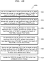
- FIG. 4G is a flow chart 400g illustrating various steps involved in performing a PDCP version change from a NR PDCP entity to a LTE PDCP entity during the handover, according to an embodiment as disclosed herein.
- the proposed method provides a mechanism for PDCP version change from the NR PDCP to LTE PDCP version when PDCP SN size in LTE is greater than PDCP SN size in NR PDCP.
- the various steps involved in performing the PDCP version change from the NR PDCP entity in the source base station to the LTE PDCP entity in the target base station during the handover are described in the flow chart 400d.
- the method includes setting TX_HFN to zero.
- the method includes setting RX_HFN to zero. The UE 102 initializes the HFN value to zero during the PDCP re-establishment procedure.
- the method includes setting NEXT_PDCP_TX_SN equal to value of 'N' least significant bits of TX_NEXT.
- the Next_PDCP_TX_SN from TX_NEXT (based on source SN length).
- Next_PDCP_TX_SN value of Y LSBs of TX_NEXT where Y is equal to size (in bits) of PDCP SN in NR PDCP.
- the 'N' denotes the length of PDCP SN of first PDCP entity.
- the method includes setting NEXT_PDCP_RX_SN equal to value of 'N' least significant bits of RX_NEXT.
- the Next_PDCP_RX_SN is calculated from RX_NEXT (based on source SN length).
- the Next_PDCP_RX_SN value of Y LSBs of RX_NEXT where Y is equal to size (in bits) of PDCP SN in NR PDCP.
- the 'N' denotes the length of PDCP SN of first PDCP entity.
- the method includes setting Last_Submitted_PDCP_RX_SN equal to value of 'N' least significant bits of RX_DELIV.
- the Last_Submitted_PDCP_RX_SN is calculated from RX_DELIV (based on source SN length).
- Last_Submitted_PDCP_RX_SN value of Y LSBs of RX_DELIV where Y is equal to size (in bits) of PDCP SN in NR PDCP.
- the 'N' denotes the length of PDCP SN of first PDCP entity.
- FIG. 4H is another flow chart 400h illustrating various steps involved in performing a PDCP version change from a NR PDCP entity to a LTE PDCP entity during the handover, according to an embodiment as disclosed herein.
- the various steps involved in performing the PDCP version change from the NR PDCP entity in the source base station to the LTE PDCP entity in the target base station during the handover are described in the flow chart 400e.
- the second set of state variables representing NEXT_PDCP_TX_SN, TX_HFN, NEXT_PDCP_RX_SN, RX_HFN and Last_Submitted_PDCP_RX_SN associated with the LTE PDCP entity are derived using the first set of state variables representing TX_NEXT, RX_NEXT, RX_DELIV and RX _REORD, associated with the NR PDCP entity.
- the method includes setting the TX_HFN equal to most significant bits of TX_NEXT wherein the number of most significant bits of TX_NEXT is equal to the length of HFN in second PDCP entity.
- the TX_HFN is calculated from TX_NEXT (based on target SN length).
- TX_HFN value of X1 MSBs of TX_NEXT where X1 is equal to size (in bits) of HFN in LTE PDCP.
- the method includes setting the RX_HFN equal to most significant bits of RX_NEXT wherein the number of most significant bits of RX_NEXT is equal to the length of HFN in second PDCP entity.
- the RX_HFN is calculated from RX_NEXT based on target SN length).
- RX_HFN value of X1 MSBs of RX_NEXT where X1 is equal to size (in bits) of HFN in LTE PDCP.
- the method includes setting the NEXT_PDCP_TX_SN equal to value of least significant bits of TX_NEXT wherein the number of least significant bits of TX_NEXT is equal to the length of PDCP SN of second PDCP entity.
- the Next_PDCP_TX_SN is calculated from TX_NEXT based on target SN length).
- Next_PDCP_TX_SN value of X LSBs of TX_NEXT where X is equal to size (in bits) of PDCP SN in LTE PDCP.
- the method includes setting the NEXT_PDCP_RX_SN equal to value of least significant bits of RX_NEXT wherein the number of least significant bits of RX_NEXT is equal to the length of PDCP SN of second PDCP entity.
- the Next_PDCP_RX_SN is calculated from RX_NEXT (based on target SN length).
- Next_PDCP_RX_SN value of X LSBs of RX_NEXT where X is equal to size (in bits) of PDCP SN in LTE PDCP.
- the method includes setting the Last_Submitted_PDCP_RX_SN equal to value of least significant bits of RX_DELIV wherein the length of the least significant bits of RX_DELIV is equal to the length of PDCP SN of second PDCP entity.
- the Last_Submitted_PDCP_RX_SN is calculated from RX_DELIV (based on target SN length).
- Last_Submitted_PDCP_RX_SN value of X LSBs of RX_DELIV where X is equal to size (in bits) of PDCP SN in LTE PDCP.
- the method includes updating the PDCP SN of each PDCP SDU which has undergone version change.
- the PDCP status report will be prepared based on RX_DELIV.
- the PDCP SN of each PDCP SDU which is associated with PDCP SN at the time of PDCP entity re-establishment is updated as follows:
- X is equal to size (in bits) of PDCP SN in LTE PDCP.
- Y is equal to size (in bits) of PDCP SN in NR PDCP.
- this method can also be used when PDCP SN size in NR PDCP is equal to PDCP SN size in LTE PDCP.
- FIG. 5 is a sequence diagram illustrating various steps which the UE performs a handover from a source base station to a target base station, according to an embodiment as disclosed herein.
- the FIG. 5 depicts the handover of the UE 102 connected to a source base station 104a (i.e., legacy LTE node) towards a target base station 104b (which is Rel-15 LTE node which is EN-DC capable base station).
- the source node 104a is legacy LTE node
- the radio bearer configured by LTE eNB has LTE PDCP entity.
- the target node 104b is EN-DC capable LTE eNB the radio bearer configured by EN-DC LTE eNB can have either LTE PDCP or NR PDCP.
- the handover is triggered (502) during the mobility of the UE 102 from source towards target depending on the signal strength.
- the UE 102 sends (504) a measurement report to the source base station 104a when the handover event is triggered.
- the source base station 104a i.e., LTE eNB sends (506) the handover request message to the target base station 104b i.e., EN-DC capable LTE eNB.
- the HO request message includes HandoverPreparationInformation comprising the as-Config, rrm-Config, ue-RadioAccessCapabilityInfo, as-Context etc.
- the ue-RadioAccessCapabilityInfo indicates the UE capabilities i.e.
- the UE is EN-DC capable and the as-Config includes the LTE PDCP state parameters like NEXT_PDCP_TX_SN, TX_HFN, NEXT_PDCP_RX_SN, RX_HFN, Last_Submitted_PDCP_RX_SN and Reordering_PDCP_RX_COUNT.
- the target base station 104b decides (508) whether the DRBs of the UE undergoing handover should be configured with LTE PDCP or NR PDCP.
- the DRBs of the UE need to be configured with NR PDCP then this involves PDCP version change comprising the translation of LTE PDCP state parameters sent by the source into NR PDCP parameters.
- the UE also needs to be informed whether it continues with LTE PDCP in the target or whether it needs to perform PDCP version change. This is indicated (510) to the UE 102 by the target base station 104b through the RRC container included in the Handover Acknowledgement message sent to the source base station 104a on the X2 interface.
- the source base station 104a forwards (512) the RRC container received from the target base station 104b which includes the mobility control information to the UE 102.
- the mobility control information includes at least one of the PDCP version change indication and security key change indication.
- the UE 102 does not receive the PDCP version change indication and the UE 102 switches (514) to the target base station 104b, performs (516) PDCP reestablishment operation i.e., the UE 102 shall establish the DRBs in the target based on LTE PDCP.
- the UE 102 sends (518) a handover complete command to the target base station 104b.
- FIG. 6 is a sequence diagram illustrating various steps during handover in which the UE performs a PDCP version change from LTE PDCP entity to a NR PDCP entity, according to an embodiment as disclosed herein.
- the UE 102 receives (612) the PDCP version change indication i.e., the UE 102 shall establish the DRBs in the target based on NR PDCP.
- the UE 102 After receiving the HO command message i.e. RRC reconfiguration message including mobility control information, the UE 102 either performs normal LTE PDCP re-establishment or the UE performs (616) PDCP version change operation while re-establishing the PDCP.
- the UE 102 receives the mobility control information including the PDCP version change indication (LTE PDCP to NR PDCP) and security key change indication, the UE performs the PDCP version change operation from LTE PDCP to NR PDCP while re-establishing the PDCP for the concerned DRB in the target node 104b.
- the PDCP version change from the LTE PDCP to the NR PDCP it should be noted that the NR PDCP SN size should be either equal or greater than the LTE PDCP SN size.
- the target node 104b sends the PDCP version change indication because the criterion is met.
- the mechanism for PDCP version change using the handover procedure is also applicable for signaling radio bearer (SRB) except SRB0.
- FIG. 7 is a sequence diagram illustrating various steps involved during handover of the UE connected to Rel-15 LTE node which is EN-DC capable towards legacy LTE node, according to an embodiment as disclosed herein.
- the FIG. 7 depicts the handover of the UE 102 connected to source base station 104a i.e., Rel-15 LTE node which is EN-DC capable towards the target base station 104b i.e., a legacy LTE node.
- the source base station 104a i.e. EN-DC capable LTE eNB sends (706) the handover request message to the target i.e. LTE eNB.
- the HO request message includes HandoverPreparationInformation comprising the as-Config, rrm-Config, ue-RadioAccessCapabilityInfo, as-Context etc.
- the ue-RadioAccessCapabilityInfo indicates the UE capabilities i.e., the UE is EN-DC capable and the as-Config includes the either LTE PDCP state parameters like NEXT_PDCP_TX_SN, TX_HFN, NEXT_PDCP_RX_SN, RX_HFN, Last_Submitted_PDCP_RX_SN and Reordering_PDCP_RX_COUNT or NR PDCP parameters like TX_NEXT, RX_NEXT, RX_DELIV and RX_REORD depending on whether the PDCP configuration of the DRB in the source base station 104a. Since the source node 104a is EN-DC capable LTE eNB the radio bearer configured by EN-DC LTE eNB can have either LTE PDCP or NR
- the target base station 104b decides the DRBs of the UE undergoing handover should be configured with the LTE PDCP regardless of the PDCP configuration of DRBs in the source base station 104a. If the DRBs of the UE 102 was configured with NR PDCP in the source base station 104a, then this involves PDCP version change comprising the translation of NR PDCP state parameters sent by the source base station 104a into LTE PDCP parameters, otherwise the handover is like a normal LTE handover.
- the UE 102 also needs to be informed whether it needs to perform PDCP version change if NR PDCP was configured for the DRB in the source base station or it continues with LTE PDCP in the target base station. This is indicated (710) to the UE 102 by the target base station 104a through the RRC container included in the Handover Acknowledgement message sent to the source on the X2 interface.
- the source base station 104a forwards (712) the RRC container received from the target which includes the mobility control information to the UE.
- the UE 102 receives the PDCP version change indication i.e., UE shall establish the DRBs in the target based on LTE PDCP.
- the HO command message i.e.
- RRC reconfiguration message including mobility control information the UE either perform normal LTE PDCP re-establishment or the UE performs (716) PDCP version change operation (i.e. NR PDCP to LTE PDCP) while re-establishing the PDCP.
- the UE 102 receives the mobility control information including the PDCP version change indication (NR PDCP to LTE PDCP) and security key change indication, the UE performs the PDCP version change operation from NR PDCP to LTE PDCP while re-establishing the PDCP for the concerned DRB in the target node 104b.
- the LTE PDCP SN size should be either equal or greater than the NR PDCP SN size.
- the LTE PDCP entities i.e. PDCP TX/RX entities
- the target base station 104a i.e., legacy LTE node and the UE 102 can be re-established to ensure lossless data transmission and reception.
- the PDCP version change can be lossless when the criterion is met i.e. the target node 104b determines whether a sequence number (SN) length of the first PDCP entity associated with the radio bearer configured by a source node 104a is less than or equal to a SN length of a second PDCP entity configured by a target node 104b.
- the NR PDCP SN size should be either equal or greater than the LTE PDCP SN size in FIG 6 and LTE PDCP SN size should be either equal or greater than the NR PDCP SN size in FIG 7 .
- the HO command message i.e.
- LTE RRC reconfiguration message including mobility control information sent to the UE either includes an explicit indication for PDCP version change and security key change indication or an implicit indication.
- the implicit indication is based on including the radio bearer configuration which includes the PDCP configuration. If the radio bearer configuration is a NR RRC container included LTE RRC reconfiguration message then the PDCP configuration included in the radio bearer configuration is associated with NR PDCP. If the NR RRC container is not included in the LTE RRC reconfiguration message then PDCP configuration included in LTE RRC reconfiguration message is associated with LTE PDCP.
- PDCP version change can be still realized albeit incurring data loss during handover. This is accomplished by sending the HO command message i.e. RRC reconfiguration message including mobility control information to the UE wherein the DRBs configured to the UE undergoing handover are released and the added within the same HO command message.
- the HO command message i.e. RRC reconfiguration message including mobility control information
- Handover procedure in LTE and NR triggers PDCP re-establishment procedure wherein the security key is refreshed.
- PDCP SN or count is maintained and header compression is reset.
- Once PDCP re-establishment is completed for AM DRBs from the first PDCP SDU for which the successful delivery of the corresponding PDCP Data PDU has not been confirmed by lower layers, perform retransmission or transmission of all the PDCP SDUs already associated with PDCP SNs in ascending order of the COUNT values associated to the PDCP SDU prior to the PDCP entity re-establishment.
- mapping between LTE and NR state variables to support lossless transition during version change is needed.
- Mapping method from LTE to NR PDCP version is changed when PDCP SN size is same in LTE and NR PDCP.
- NR PDCP state variables can be determined using the LTE state variables in the proposed invention as shown in Table 2 below.
- NR Parameters Derivation of NR parameters from LTE parameters TX_NEXT Next_PDCP_TX_SN + TX_HFN (2 NI *TX_HFN) + Next_PDCP_TX_SN where N1 is equal to size (in bits) of PDCP SN in LTE RX_NEXT Next_PDCP_RX_SN and RX_HFN (2 NI *RX_HFN) + Next_PDCP_RX_SN where N1 is equal to size (in bits) of PDCP SN RX_REORD Need to calculate based on PDCP and RX HFN of first received packet in DL RX_DELIV Last_Submitted_PDCP_RX_SN + RX_HFN (2 NI *RX_HFN) + Last_Submitted_PDCP_RX_SN where N1 is equal to size (in bits) of PDCP SN
- RX_REORD is not required when NR to LTE PDCP version change takes place as LTE is not supporting reordering operation for MCG DRB or standalone LTE DRB but the same is required during LTE to NR as NR always supports reordering and this need to be calculated based on first received packet in DL.
- Mapping method from NR PDCP to LTE PDCP version is changed when PDCP SN size is same in LTE and NR PDCP.
- LTE PDCP state variables can be determined using the NR state variables in the proposed invention as shown in Table 3 below.
- FIG. 8 illustrates various components of the UE 102 for performing the handover, according to an embodiment as disclosed herein.
- the primary components present for communication include a communication module 802, a control signaling module 804, a processor module 806, a memory module 808, a radio resource management module 810 and a display module 812.
- the communication module 802 is configured to decode a synchronization signal, the beam index sequence, PBCH and SBCH broadcasted by a base station (i.e., for example, a 5G eNB).
- the communication module 802 is configured to communicate RRC signaling to and from the 5G eNB 104.
- the communication module 802 in the UE 102 can be configured to communicate the measurement report and RRC reconfiguration complete message to the 5G eNB 104.
- the control signaling module 804 in the UE 102 can be configured to prepare the related RRC messages to be transmitted to the 5G eNB 104 and also can be configured to parse the related RRC message received from the 5G eNB 103.
- the processor module 806 depicts a computing environment in the UE 102 for implementing a method and system for lossless inter RAT handover in the wireless communication system.
- the computing environment comprises at least one processing unit that is equipped with a control unit and an Arithmetic Logic Unit (ALU), a clock chip, plurality of networking devices, and a plurality Input output (I/O) devices.
- the processor module 806 is responsible for processing the instructions of the algorithm.
- the processing unit receives commands from the control unit in order to perform its processing. Further, any logical and arithmetic operations involved in the execution of the instructions are computed with the help of the ALU.
- the overall computing environment can be composed of multiple homogeneous or heterogeneous cores, multiple CPUs of different kinds, special media and other accelerators.
- the processing unit is responsible for processing the instructions of the algorithm.
- the algorithm comprising of instructions and codes required for the implementation are stored in either the memory module 808 or the storage or both.
- the instructions may be fetched from the corresponding memory module 808 or storage unit, and executed by the processing unit.
- the processing unit synchronizes the operations and executes the instructions based on the timing signals generated by the clock chip.
- the embodiments of the present disclosure disclosed herein can be implemented through at least one software program running on at least one hardware device and performing network management functions to control the elements.
- the memory module 808 is also configured to store information related to UE operation.
- the radio resource management module 810 in the UE 102 is responsible for various aspects like cell level mobility and beam level mobility etc.
- the radio resource management module 810 in the UE 102 may be configured to evaluate the cell selection/re-selection handover events based on the CSI-RS measurements and perform CSI-RS RSRP measurements respectively.
- the radio resource management module 810 in the UE 102 may be configured to receive the PDCP version change indication in a handover command such as the Radio Resource Control (RRC) Reconfiguration message to perform a handover to the target base station 104b.
- RRC Radio Resource Control
- the radio resource management module 810 in the UE 102 may be configured to performing a PDCP version change to switch from the first PDCP entity to the second PDCP entity using the PDCP re-establishment procedure in response to receiving the PDCP version change indication.
- the display module 812 in the UE 102 can be configured so that user can input information or information can output on the display for the user to understand some UE 102 operations when the UE 102 is operating in dual connectivity mode of operation. Most of the UE 102 operations are transparent to the user and may not need user input or output on the display.
- the processor module 806 may comprise the control signaling module 804 and the radio resource management module 810, or perform the operations performed by the control signaling module 804 and the radio resource management module 810 described above.
- FIG. 9 is a block diagram illustrating various modules of the network (eNB/gNB) 104, according to an embodiment as disclosed herein.
- the primary blocks present in the eNB/gNB 104 for communication with the UE 102 includes a communication module 902, a control signaling module 904, a processor module 906, a memory module 908 and a radio resource management module 910.
- the communication module 1602 is configured to communicate RRC signaling to and from the UE 102.
- the communication module 1602 in the eNB/gNB 104 can be configured to transmit RRC reconfiguration message with the PDCP version change indication to the UE 102 for handover of the UE from the source eNB 104a to the target gNB 104b.
- the control signaling module 904 in the eNB/gNB 104 can be configured to prepare the related RRC messages (as described above) to be transmitted to the UE 102 and also can be configured to parse the related RRC message received from the UE 102.
- the control signaling module 904 in the eNB/gNB 104 can be configured to determine the bearer configuration.
- the processor module 906 depicts a computing environment implementing the method for performing the PDCP version change in the wireless communication system.
- the computing environment of 906 comprises at least one processing unit that is equipped with a control unit and an Arithmetic Logic Unit (ALU), a clock chip, plurality of networking devices, and a plurality Input output (I/O) devices.
- ALU Arithmetic Logic Unit
- the processor module 906 is responsible for processing the instructions of the algorithm.
- the processing unit receives commands from the control unit in order to perform its processing. Further, any logical and arithmetic operations involved in the execution of the instructions are computed with the help of the ALU.
- the overall computing environment can be composed of multiple homogeneous or heterogeneous cores, multiple CPUs of different kinds, special media and other accelerators.
- the processing unit is responsible for processing the instructions of the algorithm.
- the algorithm comprising of instructions and codes required for the implementation are stored in either the memory module 908 or the storage or both.
- the instructions may be fetched from the corresponding memory module 908 or storage unit, and executed by the processing unit.
- the processing unit synchronizes the operations and executes the instructions based on the timing signals generated by the clock chip.
- the embodiments of the present disclosure disclosed herein can be implemented through at least one software program running on at least one hardware device and performing network management functions to control the elements.
- the memory module 908 is also configured to store information related to operation of the eNB/gNB 104 and the UE 102.
- the radio resource management module 910 in the eNB/gNB 104 may be configured to evaluate the handover decisions (based on the measurement reports sent by one or more UEs 102a-102n).
- the processor module 906 can be may comprise the control signaling module 904 and the radio resource management module 910, or perform the operations performed by the control signaling module 904 and the radio resource management module 910 described above.
- FIG. 10 illustrates a UE according to another embodiment of the present disclosure.
- the UE may correspond to the UE 1000.
- the UE 1000 may include a processor 1010, a transceiver 1004 and a memory 1006. However, all of the illustrated components are not essential. The UE 1000 may be implemented by more or less components than those illustrated in FIG. 10 . In addition, the processor 1010 and the transceiver 1004 and the memory 1006 may be implemented as a single chip according to another embodiment.
- the processor 1010 may include one or more processors or other processing devices that control the proposed function, process, and/or method. Operation of the UE 1000 may be implemented by the processor 1010.
- the processor 1010 may detect a PDCCH on a configured control resource set.
- the processor 1010 determines a method for dividing CBs and a method for rate matching of a PDSCH according to the PDCCH.
- the processor 1010 may control the transceiver 1004 to receive the PDSCH according to the PDCCH.
- the processor 1010 may generate HARQ-ACK information according to the PDSCH.
- the processor 1010 may control the transceiver 1004 to transmit the HARQ-ACK information.
- the transceiver 1004 may include a RF transmitter for up-converting and amplifying a transmitted signal, and a RF receiver for down-converting a frequency of a received signal.
- the transceiver 1004 may be implemented by more or less components than those illustrated in components.
- the transceiver 1004 may be connected to the processor 1010 and transmit and/or receive a signal.
- the signal may include control information and data.
- the transceiver 1004 may receive the signal through a wireless channel and output the signal to the processor 1010.
- the transceiver 1004 may transmit a signal output from the processor 1010 through the wireless channel.
- the memory 1006 may store the control information or the data included in a signal obtained by the UE 1000.
- the memory 1006 may be connected to the processor 1010 and store at least one instruction or a protocol or a parameter for the proposed function, process, and/or method.
- the memory 1006 may include read-only memory (ROM) and/or random access memory (RAM) and/or hard disk and/or CD-ROM and/or DVD and/or other storage devices.
- the embodiments disclosed herein can be implemented through at least one software program running on at least one hardware device and performing network management functions to control the elements.
Claims (12)
- Verfahren, das von einem Benutzergerät, user equipment ― UE, (1000) in einem Drahtloskommunikationssystem durchgeführt wird, wobei das Verfahren umfasst:Empfangen ― von einer Basisstation (104a) ― einer Funkressourcensteuerungs-, Radio Resource Control ― RRC, Rekonfigurationsnachricht, die einen PDCP-Versionsänderungsindikator oder eine NR-Funkträgerkonfiguration umfasst; undDurchführen einer Paketdatenkonvergenzprotokoll-, Packet Data Convergence Protocol ― PDCP, Versionsänderung für wenigstens einen Funkträger, radio bearer - RB, der für das UE (1000) konfiguriert ist, von einer ersten PDCP-Version einer ersten PDCP-Entität zu einer zweiten PDCP-Version einer zweiten PDCP-Entität basierend auf dem PDCP-Versionsänderungsindikator oder der NR-Funkträgerkonfiguration, die in der RRC-Rekonfigurationsnachricht enthalten ist,wobei der PDCP-Versionsänderungsindikator eine PDCP-Versionsänderung von einem New Radio-, NR, PDCP zu einem Evolved Universal Terrestrial Radio Access-, E-UTRA, PDCP angibt.
- Verfahren nach Anspruch 1, wobei die erste PDCP-Version und die zweite PDCP-Version eines aus dem E-UTRA-PDCP und dem NR-PDCP sind und
wobei die erste PDCP-Version und die zweite PDCP-Version unterschiedlich sind. - Verfahren nach Anspruch 1, wobei der wenigstens eine RB ein mit einem Masterknoten, master node ― MN, abgeschlossener Masterzellgruppen-, master cell group ― MCG, Träger ist.
- Verfahren nach Anspruch 1, wobei der wenigstens eine RB ein Signalisierungsfunkträger, Signaling Radio Bearer - SRB, ist.
- Verfahren nach Anspruch 1, wobei die PDCP-Versionsänderung von dem E-UTRA-PDCP zu dem NR-PDCP durchgeführt wird, falls in der RRC-Rekonfigurationsnachricht eine NR-Funkträgerkonfiguration enthalten ist.
- Verfahren nach Anspruch 1, wobei der wenigstens eine RB ein Signalisierungsfunkträger, Signaling Radio Bearer ― SRB, oder ein Datenfunkträger, Data Radio Bearer ― DRB, ist.
- Benutzergerät, user equipment ― UE, (1000) in einem Drahtloskommunikationssystem, wobei das UE (1000) umfasst:einen Sendeempfänger (1004); undwenigstens einen Prozessor (1010), der für Folgendes ausgestaltet ist:Empfangen ― von einer Basisstation (104a) ― einer Funkressourcensteuerungs-, Radio Resource Control ― RRC, Rekonfigurationsnachricht, die einen PDCP-Versionsänderungsindikator oder eine NR-Funkträgerkonfiguration umfasst, undDurchführen einer Paketdatenkonvergenzprotokoll-, Packet Data Convergence Protocol ― PDCP, Versionsänderung für wenigstens einen Funkträger, radio bearer ― RB, der für das UE (1000) konfiguriert ist, von einer ersten PDCP-Version einer ersten PDCP-Entität zu einer zweiten PDCP-Version einer zweiten PDCP-Entität basierend auf dem PDCP-Versionsänderungsindikator oder der NR-Funkträgerkonfiguration, die in der RRC-Rekonfigurationsnachricht enthalten ist,wobei der PDCP-Versionsänderungsindikator eine PDCP-Versionsänderung von einem New Radio-, NR, PDCP zu einem Evolved Universal Terrestrial Radio Access-, E-UTRA, PDCP angibt.
- UE (1000) nach Anspruch 7, wobei die erste PDCP-Version und die zweite PDCP-Version eines aus dem E-UTRA-PDCP und dem NR-PDCP sind und
wobei die erste PDCP-Version und die zweite PDCP-Version unterschiedlich sind. - UE (1000) nach Anspruch 7, wobei der wenigstens eine RB ein mit einem Masterknoten, master node ― MN, abgeschlossener Masterzellgruppen-, master cell group ― MCG, Träger ist.
- UE (1000) nach Anspruch 7, wobei der wenigstens eine RB ein Signalisierungsfunkträger, Signaling Radio Bearer - SRB, ist.
- UE (1000) nach Anspruch 7, wobei die PDCP-Versionsänderung von dem E-UTRA-PDCP zu dem NR-PDCP durchgeführt wird, falls in der RRC-Rekonfigurationsnachricht eine NR-Funkträgerkonfiguration enthalten ist.
- UE (1000) nach Anspruch 7, wobei der wenigstens eine RB ein Signalisierungsfunkträger, Signaling Radio Bearer ― SRB, oder ein Datenfunkträger, Data Radio Bearer ― DRB, ist.
Applications Claiming Priority (2)
| Application Number | Priority Date | Filing Date | Title |
|---|---|---|---|
| IN201741028700 | 2017-08-11 | ||
| PCT/KR2018/009274 WO2019031947A1 (en) | 2017-08-11 | 2018-08-13 | METHOD AND SYSTEM FOR REALIZING TRANSFER IN A WIRELESS COMMUNICATION NETWORK |
Publications (3)
| Publication Number | Publication Date |
|---|---|
| EP3662700A1 EP3662700A1 (de) | 2020-06-10 |
| EP3662700A4 EP3662700A4 (de) | 2020-06-17 |
| EP3662700B1 true EP3662700B1 (de) | 2021-10-27 |
Family
ID=65278988
Family Applications (1)
| Application Number | Title | Priority Date | Filing Date |
|---|---|---|---|
| EP18842954.2A Active EP3662700B1 (de) | 2017-08-11 | 2018-08-13 | Verfahren und system zur übergabe in einem drahtloskommunikationsnetz |
Country Status (4)
| Country | Link |
|---|---|
| US (1) | US11337118B2 (de) |
| EP (1) | EP3662700B1 (de) |
| CN (1) | CN111034259B (de) |
| WO (1) | WO2019031947A1 (de) |
Families Citing this family (11)
| Publication number | Priority date | Publication date | Assignee | Title |
|---|---|---|---|---|
| KR20200051045A (ko) * | 2017-09-28 | 2020-05-12 | 삼성전자주식회사 | 무선 통신 시스템에서의 pdcp 동작 처리를 위한 방법 및 시스템 |
| DK3513617T3 (da) | 2017-11-15 | 2021-08-02 | Ericsson Telefon Ab L M | Håndtering af PDCP under genetablering af forbindelse |
| CN111345066B (zh) * | 2017-11-16 | 2022-07-19 | 瑞典爱立信有限公司 | Pdcp版本改变的处理 |
| JP2019121834A (ja) | 2017-12-28 | 2019-07-22 | シャープ株式会社 | 端末装置、基地局装置、通信方法、および、集積回路 |
| KR102556490B1 (ko) | 2018-06-04 | 2023-07-17 | 삼성전자주식회사 | 무선 통신 시스템에서 암호화 및 복호화 처리를 가속화하는 방법 및 장치 |
| CN110636640B (zh) * | 2018-06-22 | 2023-09-22 | 华为技术有限公司 | 一种多制式双连接中的通信方法和通信装置 |
| CN111726840B (zh) * | 2019-03-21 | 2021-09-24 | 大唐移动通信设备有限公司 | 一种终端的双连接配置处理方法及装置 |
| WO2020243291A1 (en) * | 2019-05-29 | 2020-12-03 | Google Llc | Sequence number transfer for radio bearers |
| US20220361063A1 (en) * | 2019-10-03 | 2022-11-10 | Lg Electronics Inc. | Method and apparatus for applying target network configuration by user equipment in wireless communication system |
| EP4353006A1 (de) * | 2021-06-07 | 2024-04-17 | QUALCOMM Incorporated | Mobilitätsverwaltung mit doppelter konnektivität mit l2-ue-to-network-relais |
| US11910448B2 (en) * | 2021-12-28 | 2024-02-20 | T-Mobile Innovations Llc | Random access channel preamble assignments for dual connectivity |
Family Cites Families (22)
| Publication number | Priority date | Publication date | Assignee | Title |
|---|---|---|---|---|
| EP1978762A1 (de) * | 2007-04-05 | 2008-10-08 | Matsushita Electric Industrial Co., Ltd. | Dienstinhaltsynchronisierung von Multicastdaten für sich zwischen Netzen mit verschiedenen Funkzugriffstechnologien bewegenden mobilen Knoten |
| KR102040883B1 (ko) * | 2012-08-23 | 2019-11-05 | 인터디지탈 패튼 홀딩스, 인크 | 무선 시스템에서의 다중 스케줄러들을 이용한 동작 |
| KR20140107088A (ko) | 2013-02-27 | 2014-09-04 | 주식회사 케이티 | 스몰셀 환경에서 단말의 버퍼상태보고 전송방법 및 장치 |
| JP6240747B2 (ja) * | 2013-04-02 | 2017-11-29 | エルジー エレクトロニクス インコーポレイティド | 無線通信システムでセル変更手順を行うための方法及びこのための装置 |
| EP2835925B1 (de) | 2013-08-09 | 2018-08-08 | Panasonic Intellectual Property Corporation of America | Effiziente Statusberichterstattung für UE bei der dualen Konnektivität während der Mobilität |
| US10172066B2 (en) | 2013-10-23 | 2019-01-01 | Telefonaktiebolaget Lm Ericsson (Publ) | Flexible bearer handling |
| CN105684491B (zh) | 2013-10-30 | 2020-02-07 | 株式会社Kt | 用于在移动通信网络中配置双连接的方法及其装置 |
| US10206147B2 (en) | 2013-12-19 | 2019-02-12 | Qualcomm Incorporated | Serving gateway relocation and secondary node eligibility for dual connectivity |
| KR101640681B1 (ko) | 2014-01-16 | 2016-07-19 | 주식회사 케이티 | 듀얼 커넥티비티에서 기지국 변경 방법 및 그 장치 |
| EP2922326B1 (de) | 2014-03-21 | 2018-12-19 | Sun Patent Trust | Sicherheitsschlüsselableitung bei dualer Konnektivität |
| KR102022157B1 (ko) | 2014-03-28 | 2019-09-17 | 후지쯔 가부시끼가이샤 | 베어러 관리 장치, 방법 및 통신 시스템 |
| CN106465080B (zh) * | 2014-04-15 | 2020-02-07 | 诺基亚通信公司 | 用于基于承载的系统和无承载系统之间的互通的方法和装置 |
| US20170215225A1 (en) | 2014-08-07 | 2017-07-27 | Lg Electronics Inc. | Method for processing a packet data convergence protocol packet data unit at a user equipment in a dual connectivity systme and device therefor |
| US20160226632A1 (en) | 2015-01-29 | 2016-08-04 | Intel IP Corporation | Carrier aggregation enhancements for unlicensed spectrum and 5g |
| SG11201510546TA (en) | 2015-02-13 | 2016-09-29 | Ericsson Telefon Ab L M | Establishment of dual connectivity |
| US10440626B2 (en) | 2015-03-20 | 2019-10-08 | Parallel Wireless, Inc. | Content-aware inter-RAT RAB steering |
| EP3326408B1 (de) | 2015-07-22 | 2020-04-01 | Intel IP Corporation | Konvergenzschicht für 5g-kommunikationssysteme |
| US10425861B2 (en) | 2016-02-04 | 2019-09-24 | Samsung Electronics Co., Ltd. | Method and apparatus for preventing loss of data packets |
| US10285028B2 (en) * | 2016-02-05 | 2019-05-07 | Qualcomm Incorporated | Adaptive radio link monitoring |
| CN106231637B (zh) * | 2016-07-29 | 2019-10-22 | 深圳市金立通信设备有限公司 | 辅小区变换方法、装置以及基站 |
| CN107018542A (zh) | 2017-03-27 | 2017-08-04 | 中兴通讯股份有限公司 | 网络系统中状态信息的处理方法、装置及存储介质 |
| CN111096061A (zh) * | 2017-06-16 | 2020-05-01 | 苹果公司 | 用于承载类型更改的l2处理 |
-
2018
- 2018-08-13 WO PCT/KR2018/009274 patent/WO2019031947A1/en unknown
- 2018-08-13 EP EP18842954.2A patent/EP3662700B1/de active Active
- 2018-08-13 US US16/638,442 patent/US11337118B2/en active Active
- 2018-08-13 CN CN201880052072.7A patent/CN111034259B/zh active Active
Also Published As
| Publication number | Publication date |
|---|---|
| WO2019031947A1 (en) | 2019-02-14 |
| EP3662700A1 (de) | 2020-06-10 |
| US11337118B2 (en) | 2022-05-17 |
| CN111034259B (zh) | 2022-03-01 |
| CN111034259A (zh) | 2020-04-17 |
| EP3662700A4 (de) | 2020-06-17 |
| US20200178128A1 (en) | 2020-06-04 |
Similar Documents
| Publication | Publication Date | Title |
|---|---|---|
| EP3662700B1 (de) | Verfahren und system zur übergabe in einem drahtloskommunikationsnetz | |
| EP3659391B1 (de) | Verfahren zur trägertypenänderung einer vielzahl von trägern, die für benutzergeräte konfiguriert sind | |
| US11716783B2 (en) | Method and user equipment for handling user plane in dual connectivity in wireless communication system | |
| US11395365B2 (en) | Method and system for handling PDCP operation in wireless communication system | |
| KR102420991B1 (ko) | 무선통신 시스템에서 사용자 평면 동작을 관리하기 위한 방법 및 장치 | |
| EP3785485B1 (de) | Verfahren und vorrichtung zur durchführung dualer konnektivität in einem heterogenen netzwerk | |
| US11863372B2 (en) | Apparatus and method for performing dual connectivity in wireless communication system | |
| KR20200000283A (ko) | 이동통신 시스템에서 무선 링크 실패 보고 방법 및 장치 | |
| KR20200073626A (ko) | 차세대 무선 통신 시스템에서 조건부 핸드오버의 실패 타이머 운용방법 | |
| US20230354116A1 (en) | Method and apparatus for performing conditional pscell change procedure in next-generation mobile communication system | |
| WO2020088611A1 (zh) | 一种重置mac层、数据传输方法及装置 | |
| US20220386196A1 (en) | Method and device for handing over terminal in wireless communication system using artificial intelligence | |
| US20220394799A1 (en) | Method and device for segmenting downlink radio resource control message in next-generation mobile communication system |
Legal Events
| Date | Code | Title | Description |
|---|---|---|---|
| STAA | Information on the status of an ep patent application or granted ep patent |
Free format text: STATUS: THE INTERNATIONAL PUBLICATION HAS BEEN MADE |
|
| PUAI | Public reference made under article 153(3) epc to a published international application that has entered the european phase |
Free format text: ORIGINAL CODE: 0009012 |
|
| STAA | Information on the status of an ep patent application or granted ep patent |
Free format text: STATUS: REQUEST FOR EXAMINATION WAS MADE |
|
| 17P | Request for examination filed |
Effective date: 20200306 |
|
| AK | Designated contracting states |
Kind code of ref document: A1 Designated state(s): AL AT BE BG CH CY CZ DE DK EE ES FI FR GB GR HR HU IE IS IT LI LT LU LV MC MK MT NL NO PL PT RO RS SE SI SK SM TR |
|
| AX | Request for extension of the european patent |
Extension state: BA ME |
|
| A4 | Supplementary search report drawn up and despatched |
Effective date: 20200518 |
|
| RIC1 | Information provided on ipc code assigned before grant |
Ipc: H04W 36/14 20090101AFI20200512BHEP Ipc: H04W 36/00 20090101ALI20200512BHEP Ipc: H04W 12/04 20090101ALI20200512BHEP |
|
| DAV | Request for validation of the european patent (deleted) | ||
| DAX | Request for extension of the european patent (deleted) | ||
| REG | Reference to a national code |
Ref country code: DE Ref legal event code: R079 Ref document number: 602018025872 Country of ref document: DE Free format text: PREVIOUS MAIN CLASS: H04W0036000000 Ipc: H04W0036140000 |
|
| GRAP | Despatch of communication of intention to grant a patent |
Free format text: ORIGINAL CODE: EPIDOSNIGR1 |
|
| STAA | Information on the status of an ep patent application or granted ep patent |
Free format text: STATUS: GRANT OF PATENT IS INTENDED |
|
| RIC1 | Information provided on ipc code assigned before grant |
Ipc: H04W 12/04 20210101ALI20210506BHEP Ipc: H04W 36/00 20090101ALI20210506BHEP Ipc: H04W 36/14 20090101AFI20210506BHEP |
|
| INTG | Intention to grant announced |
Effective date: 20210607 |
|
| RIN1 | Information on inventor provided before grant (corrected) |
Inventor name: AGIWAL, ANIL Inventor name: SHARMA, NEHA Inventor name: INGALE, MANGESH ABHIMANYU |
|
| GRAS | Grant fee paid |
Free format text: ORIGINAL CODE: EPIDOSNIGR3 |
|
| GRAA | (expected) grant |
Free format text: ORIGINAL CODE: 0009210 |
|
| STAA | Information on the status of an ep patent application or granted ep patent |
Free format text: STATUS: THE PATENT HAS BEEN GRANTED |
|
| AK | Designated contracting states |
Kind code of ref document: B1 Designated state(s): AL AT BE BG CH CY CZ DE DK EE ES FI FR GB GR HR HU IE IS IT LI LT LU LV MC MK MT NL NO PL PT RO RS SE SI SK SM TR |
|
| REG | Reference to a national code |
Ref country code: GB Ref legal event code: FG4D |
|
| REG | Reference to a national code |
Ref country code: CH Ref legal event code: EP |
|
| REG | Reference to a national code |
Ref country code: AT Ref legal event code: REF Ref document number: 1443040 Country of ref document: AT Kind code of ref document: T Effective date: 20211115 |
|
| REG | Reference to a national code |
Ref country code: DE Ref legal event code: R096 Ref document number: 602018025872 Country of ref document: DE |
|
| REG | Reference to a national code |
Ref country code: IE Ref legal event code: FG4D |
|
| REG | Reference to a national code |
Ref country code: NL Ref legal event code: FP |
|
| REG | Reference to a national code |
Ref country code: LT Ref legal event code: MG9D |
|
| REG | Reference to a national code |
Ref country code: AT Ref legal event code: MK05 Ref document number: 1443040 Country of ref document: AT Kind code of ref document: T Effective date: 20211027 |
|
| PG25 | Lapsed in a contracting state [announced via postgrant information from national office to epo] |
Ref country code: RS Free format text: LAPSE BECAUSE OF FAILURE TO SUBMIT A TRANSLATION OF THE DESCRIPTION OR TO PAY THE FEE WITHIN THE PRESCRIBED TIME-LIMIT Effective date: 20211027 Ref country code: LT Free format text: LAPSE BECAUSE OF FAILURE TO SUBMIT A TRANSLATION OF THE DESCRIPTION OR TO PAY THE FEE WITHIN THE PRESCRIBED TIME-LIMIT Effective date: 20211027 Ref country code: FI Free format text: LAPSE BECAUSE OF FAILURE TO SUBMIT A TRANSLATION OF THE DESCRIPTION OR TO PAY THE FEE WITHIN THE PRESCRIBED TIME-LIMIT Effective date: 20211027 Ref country code: BG Free format text: LAPSE BECAUSE OF FAILURE TO SUBMIT A TRANSLATION OF THE DESCRIPTION OR TO PAY THE FEE WITHIN THE PRESCRIBED TIME-LIMIT Effective date: 20220127 Ref country code: AT Free format text: LAPSE BECAUSE OF FAILURE TO SUBMIT A TRANSLATION OF THE DESCRIPTION OR TO PAY THE FEE WITHIN THE PRESCRIBED TIME-LIMIT Effective date: 20211027 |
|
| PG25 | Lapsed in a contracting state [announced via postgrant information from national office to epo] |
Ref country code: IS Free format text: LAPSE BECAUSE OF FAILURE TO SUBMIT A TRANSLATION OF THE DESCRIPTION OR TO PAY THE FEE WITHIN THE PRESCRIBED TIME-LIMIT Effective date: 20220227 Ref country code: SE Free format text: LAPSE BECAUSE OF FAILURE TO SUBMIT A TRANSLATION OF THE DESCRIPTION OR TO PAY THE FEE WITHIN THE PRESCRIBED TIME-LIMIT Effective date: 20211027 Ref country code: PT Free format text: LAPSE BECAUSE OF FAILURE TO SUBMIT A TRANSLATION OF THE DESCRIPTION OR TO PAY THE FEE WITHIN THE PRESCRIBED TIME-LIMIT Effective date: 20220228 Ref country code: PL Free format text: LAPSE BECAUSE OF FAILURE TO SUBMIT A TRANSLATION OF THE DESCRIPTION OR TO PAY THE FEE WITHIN THE PRESCRIBED TIME-LIMIT Effective date: 20211027 Ref country code: NO Free format text: LAPSE BECAUSE OF FAILURE TO SUBMIT A TRANSLATION OF THE DESCRIPTION OR TO PAY THE FEE WITHIN THE PRESCRIBED TIME-LIMIT Effective date: 20220127 Ref country code: LV Free format text: LAPSE BECAUSE OF FAILURE TO SUBMIT A TRANSLATION OF THE DESCRIPTION OR TO PAY THE FEE WITHIN THE PRESCRIBED TIME-LIMIT Effective date: 20211027 Ref country code: HR Free format text: LAPSE BECAUSE OF FAILURE TO SUBMIT A TRANSLATION OF THE DESCRIPTION OR TO PAY THE FEE WITHIN THE PRESCRIBED TIME-LIMIT Effective date: 20211027 Ref country code: GR Free format text: LAPSE BECAUSE OF FAILURE TO SUBMIT A TRANSLATION OF THE DESCRIPTION OR TO PAY THE FEE WITHIN THE PRESCRIBED TIME-LIMIT Effective date: 20220128 Ref country code: ES Free format text: LAPSE BECAUSE OF FAILURE TO SUBMIT A TRANSLATION OF THE DESCRIPTION OR TO PAY THE FEE WITHIN THE PRESCRIBED TIME-LIMIT Effective date: 20211027 |
|
| REG | Reference to a national code |
Ref country code: DE Ref legal event code: R097 Ref document number: 602018025872 Country of ref document: DE |
|
| PG25 | Lapsed in a contracting state [announced via postgrant information from national office to epo] |
Ref country code: SM Free format text: LAPSE BECAUSE OF FAILURE TO SUBMIT A TRANSLATION OF THE DESCRIPTION OR TO PAY THE FEE WITHIN THE PRESCRIBED TIME-LIMIT Effective date: 20211027 Ref country code: SK Free format text: LAPSE BECAUSE OF FAILURE TO SUBMIT A TRANSLATION OF THE DESCRIPTION OR TO PAY THE FEE WITHIN THE PRESCRIBED TIME-LIMIT Effective date: 20211027 Ref country code: RO Free format text: LAPSE BECAUSE OF FAILURE TO SUBMIT A TRANSLATION OF THE DESCRIPTION OR TO PAY THE FEE WITHIN THE PRESCRIBED TIME-LIMIT Effective date: 20211027 Ref country code: EE Free format text: LAPSE BECAUSE OF FAILURE TO SUBMIT A TRANSLATION OF THE DESCRIPTION OR TO PAY THE FEE WITHIN THE PRESCRIBED TIME-LIMIT Effective date: 20211027 Ref country code: DK Free format text: LAPSE BECAUSE OF FAILURE TO SUBMIT A TRANSLATION OF THE DESCRIPTION OR TO PAY THE FEE WITHIN THE PRESCRIBED TIME-LIMIT Effective date: 20211027 Ref country code: CZ Free format text: LAPSE BECAUSE OF FAILURE TO SUBMIT A TRANSLATION OF THE DESCRIPTION OR TO PAY THE FEE WITHIN THE PRESCRIBED TIME-LIMIT Effective date: 20211027 |
|
| PLBE | No opposition filed within time limit |
Free format text: ORIGINAL CODE: 0009261 |
|
| STAA | Information on the status of an ep patent application or granted ep patent |
Free format text: STATUS: NO OPPOSITION FILED WITHIN TIME LIMIT |
|
| 26N | No opposition filed |
Effective date: 20220728 |
|
| PG25 | Lapsed in a contracting state [announced via postgrant information from national office to epo] |
Ref country code: AL Free format text: LAPSE BECAUSE OF FAILURE TO SUBMIT A TRANSLATION OF THE DESCRIPTION OR TO PAY THE FEE WITHIN THE PRESCRIBED TIME-LIMIT Effective date: 20211027 |
|
| PG25 | Lapsed in a contracting state [announced via postgrant information from national office to epo] |
Ref country code: SI Free format text: LAPSE BECAUSE OF FAILURE TO SUBMIT A TRANSLATION OF THE DESCRIPTION OR TO PAY THE FEE WITHIN THE PRESCRIBED TIME-LIMIT Effective date: 20211027 |
|
| PG25 | Lapsed in a contracting state [announced via postgrant information from national office to epo] |
Ref country code: MC Free format text: LAPSE BECAUSE OF FAILURE TO SUBMIT A TRANSLATION OF THE DESCRIPTION OR TO PAY THE FEE WITHIN THE PRESCRIBED TIME-LIMIT Effective date: 20211027 |
|
| REG | Reference to a national code |
Ref country code: CH Ref legal event code: PL |
|
| PG25 | Lapsed in a contracting state [announced via postgrant information from national office to epo] |
Ref country code: LU Free format text: LAPSE BECAUSE OF NON-PAYMENT OF DUE FEES Effective date: 20220813 Ref country code: LI Free format text: LAPSE BECAUSE OF NON-PAYMENT OF DUE FEES Effective date: 20220831 Ref country code: CH Free format text: LAPSE BECAUSE OF NON-PAYMENT OF DUE FEES Effective date: 20220831 |
|
| REG | Reference to a national code |
Ref country code: BE Ref legal event code: MM Effective date: 20220831 |
|
| PG25 | Lapsed in a contracting state [announced via postgrant information from national office to epo] |
Ref country code: IT Free format text: LAPSE BECAUSE OF FAILURE TO SUBMIT A TRANSLATION OF THE DESCRIPTION OR TO PAY THE FEE WITHIN THE PRESCRIBED TIME-LIMIT Effective date: 20211027 |
|
| PG25 | Lapsed in a contracting state [announced via postgrant information from national office to epo] |
Ref country code: IE Free format text: LAPSE BECAUSE OF NON-PAYMENT OF DUE FEES Effective date: 20220813 Ref country code: FR Free format text: LAPSE BECAUSE OF NON-PAYMENT OF DUE FEES Effective date: 20220831 |
|
| PGFP | Annual fee paid to national office [announced via postgrant information from national office to epo] |
Ref country code: NL Payment date: 20230721 Year of fee payment: 6 |
|
| PG25 | Lapsed in a contracting state [announced via postgrant information from national office to epo] |
Ref country code: BE Free format text: LAPSE BECAUSE OF NON-PAYMENT OF DUE FEES Effective date: 20220831 |
|
| PGFP | Annual fee paid to national office [announced via postgrant information from national office to epo] |
Ref country code: GB Payment date: 20230720 Year of fee payment: 6 |
|
| PGFP | Annual fee paid to national office [announced via postgrant information from national office to epo] |
Ref country code: DE Payment date: 20230720 Year of fee payment: 6 |
|
| PG25 | Lapsed in a contracting state [announced via postgrant information from national office to epo] |
Ref country code: CY Free format text: LAPSE BECAUSE OF FAILURE TO SUBMIT A TRANSLATION OF THE DESCRIPTION OR TO PAY THE FEE WITHIN THE PRESCRIBED TIME-LIMIT Effective date: 20211027 |