EP3662344B1 - Sanitärsteuerungssystem - Google Patents
Sanitärsteuerungssystem Download PDFInfo
- Publication number
- EP3662344B1 EP3662344B1 EP18841642.4A EP18841642A EP3662344B1 EP 3662344 B1 EP3662344 B1 EP 3662344B1 EP 18841642 A EP18841642 A EP 18841642A EP 3662344 B1 EP3662344 B1 EP 3662344B1
- Authority
- EP
- European Patent Office
- Prior art keywords
- sensor
- pcd
- measured data
- mobile device
- microcontroller
- Prior art date
- Legal status (The legal status is an assumption and is not a legal conclusion. Google has not performed a legal analysis and makes no representation as to the accuracy of the status listed.)
- Active
Links
Images

Classifications
-
- G—PHYSICS
- G01—MEASURING; TESTING
- G01F—MEASURING VOLUME, VOLUME FLOW, MASS FLOW OR LIQUID LEVEL; METERING BY VOLUME
- G01F15/00—Details of, or accessories for, apparatus of groups G01F1/00 - G01F13/00 insofar as such details or appliances are not adapted to particular types of such apparatus
- G01F15/06—Indicating or recording devices
- G01F15/061—Indicating or recording devices for remote indication
- G01F15/063—Indicating or recording devices for remote indication using electrical means
-
- G—PHYSICS
- G05—CONTROLLING; REGULATING
- G05B—CONTROL OR REGULATING SYSTEMS IN GENERAL; FUNCTIONAL ELEMENTS OF SUCH SYSTEMS; MONITORING OR TESTING ARRANGEMENTS FOR SUCH SYSTEMS OR ELEMENTS
- G05B19/00—Program-control systems
- G05B19/02—Program-control systems electric
- G05B19/04—Program control other than numerical control, i.e. in sequence controllers or logic controllers
- G05B19/042—Program control other than numerical control, i.e. in sequence controllers or logic controllers using digital processors
-
- G—PHYSICS
- G01—MEASURING; TESTING
- G01D—MEASURING NOT SPECIALLY ADAPTED FOR A SPECIFIC VARIABLE; ARRANGEMENTS FOR MEASURING TWO OR MORE VARIABLES NOT COVERED IN A SINGLE OTHER SUBCLASS; TARIFF METERING APPARATUS; MEASURING OR TESTING NOT OTHERWISE PROVIDED FOR
- G01D21/00—Measuring or testing not otherwise provided for
- G01D21/02—Measuring two or more variables by means not covered by a single other subclass
-
- G—PHYSICS
- G06—COMPUTING OR CALCULATING; COUNTING
- G06F—ELECTRIC DIGITAL DATA PROCESSING
- G06F1/00—Details not covered by groups G06F3/00 - G06F13/00 and G06F21/00
- G06F1/26—Power supply means, e.g. regulation thereof
- G06F1/32—Means for saving power
- G06F1/3203—Power management, i.e. event-based initiation of a power-saving mode
- G06F1/3206—Monitoring of events, devices or parameters that trigger a change in power modality
- G06F1/3209—Monitoring remote activity, e.g. over telephone lines or network connections
-
- G—PHYSICS
- G06—COMPUTING OR CALCULATING; COUNTING
- G06F—ELECTRIC DIGITAL DATA PROCESSING
- G06F1/00—Details not covered by groups G06F3/00 - G06F13/00 and G06F21/00
- G06F1/26—Power supply means, e.g. regulation thereof
- G06F1/32—Means for saving power
- G06F1/3203—Power management, i.e. event-based initiation of a power-saving mode
- G06F1/3234—Power saving characterised by the action undertaken
- G06F1/3243—Power saving in microcontroller unit
-
- H—ELECTRICITY
- H04—ELECTRIC COMMUNICATION TECHNIQUE
- H04B—TRANSMISSION
- H04B5/00—Near-field transmission systems, e.g. inductive or capacitive transmission systems
- H04B5/70—Near-field transmission systems, e.g. inductive or capacitive transmission systems specially adapted for specific purposes
-
- H—ELECTRICITY
- H04—ELECTRIC COMMUNICATION TECHNIQUE
- H04W—WIRELESS COMMUNICATION NETWORKS
- H04W4/00—Services specially adapted for wireless communication networks; Facilities therefor
- H04W4/80—Services using short range communication, e.g. near-field communication [NFC], radio-frequency identification [RFID] or low energy communication
-
- G—PHYSICS
- G01—MEASURING; TESTING
- G01F—MEASURING VOLUME, VOLUME FLOW, MASS FLOW OR LIQUID LEVEL; METERING BY VOLUME
- G01F1/00—Measuring the volume flow or mass flow of fluid or fluent solid material wherein the fluid passes through a meter in a continuous flow
-
- G—PHYSICS
- G05—CONTROLLING; REGULATING
- G05B—CONTROL OR REGULATING SYSTEMS IN GENERAL; FUNCTIONAL ELEMENTS OF SUCH SYSTEMS; MONITORING OR TESTING ARRANGEMENTS FOR SUCH SYSTEMS OR ELEMENTS
- G05B2219/00—Program-control systems
- G05B2219/20—Pc systems
- G05B2219/25—Pc structure of the system
- G05B2219/25167—Receive commands through mobile telephone
-
- G—PHYSICS
- G05—CONTROLLING; REGULATING
- G05B—CONTROL OR REGULATING SYSTEMS IN GENERAL; FUNCTIONAL ELEMENTS OF SUCH SYSTEMS; MONITORING OR TESTING ARRANGEMENTS FOR SUCH SYSTEMS OR ELEMENTS
- G05B2219/00—Program-control systems
- G05B2219/20—Pc systems
- G05B2219/25—Pc structure of the system
- G05B2219/25354—Power or secondary control signal derived from received signal
-
- G—PHYSICS
- G05—CONTROLLING; REGULATING
- G05B—CONTROL OR REGULATING SYSTEMS IN GENERAL; FUNCTIONAL ELEMENTS OF SUCH SYSTEMS; MONITORING OR TESTING ARRANGEMENTS FOR SUCH SYSTEMS OR ELEMENTS
- G05B2219/00—Program-control systems
- G05B2219/20—Pc systems
- G05B2219/25—Pc structure of the system
- G05B2219/25428—Field device
-
- G—PHYSICS
- G05—CONTROLLING; REGULATING
- G05B—CONTROL OR REGULATING SYSTEMS IN GENERAL; FUNCTIONAL ELEMENTS OF SUCH SYSTEMS; MONITORING OR TESTING ARRANGEMENTS FOR SUCH SYSTEMS OR ELEMENTS
- G05B2219/00—Program-control systems
- G05B2219/30—Nc systems
- G05B2219/31—From computer integrated manufacturing till monitoring
- G05B2219/31125—Signal, sensor adapted interfaces build into fielddevice
-
- G—PHYSICS
- G05—CONTROLLING; REGULATING
- G05B—CONTROL OR REGULATING SYSTEMS IN GENERAL; FUNCTIONAL ELEMENTS OF SUCH SYSTEMS; MONITORING OR TESTING ARRANGEMENTS FOR SUCH SYSTEMS OR ELEMENTS
- G05B2219/00—Program-control systems
- G05B2219/30—Nc systems
- G05B2219/31—From computer integrated manufacturing till monitoring
- G05B2219/31197—Near field communication nfc
-
- G—PHYSICS
- G05—CONTROLLING; REGULATING
- G05B—CONTROL OR REGULATING SYSTEMS IN GENERAL; FUNCTIONAL ELEMENTS OF SUCH SYSTEMS; MONITORING OR TESTING ARRANGEMENTS FOR SUCH SYSTEMS OR ELEMENTS
- G05B2219/00—Program-control systems
- G05B2219/30—Nc systems
- G05B2219/31—From computer integrated manufacturing till monitoring
- G05B2219/31211—Communicate diagnostic data from intelligent field device controller to central
-
- Y—GENERAL TAGGING OF NEW TECHNOLOGICAL DEVELOPMENTS; GENERAL TAGGING OF CROSS-SECTIONAL TECHNOLOGIES SPANNING OVER SEVERAL SECTIONS OF THE IPC; TECHNICAL SUBJECTS COVERED BY FORMER USPC CROSS-REFERENCE ART COLLECTIONS [XRACs] AND DIGESTS
- Y02—TECHNOLOGIES OR APPLICATIONS FOR MITIGATION OR ADAPTATION AGAINST CLIMATE CHANGE
- Y02A—TECHNOLOGIES FOR ADAPTATION TO CLIMATE CHANGE
- Y02A20/00—Water conservation; Efficient water supply; Efficient water use
- Y02A20/15—Leakage reduction or detection in water storage or distribution
Definitions
- the present disclosure relates to plumbing control devices ("PCD”), such as water pressure regulating valves and hot water mixing valves for residential and commercial use. More particularly, the present disclosure relates to improved systems of sensing characteristics, such as temperatures and pressures, in water passing through unpowered PCDs and making manual adjustments to the PCDs based on the sensed characteristics.
- PCD plumbing control devices
- sensing characteristics such as temperatures and pressures
- the plumbing system may have a plurality of components, including different types of PCDs, such as pressure regulating valves, hot water mixing valves, and the like. Often, it is helpful to measure various characteristics of the fluid within the system, for example, temperature or pressure.
- thermometers are used to take temperature readings and analog or digital gauges are used to take pressure readings.
- thermometers usually require a location, such as a faucet, where water is discharged from the plumbing system to take a measurement.
- pressure gauge readings must be taken from specific locations in the system, such as a valve test cock or tap, where the gauge can be placed in contact with water within the system.
- locations can be inconvenient or even impractical to access and are often set apart from areas where adjustments to the PCDs of the system can be made. In addition, these locations are often not accessible to electricity to power the sensors.
- EP 2860596 A2 discloses methods and apparatus for storing and retrieving data related to the installation, service, repair or performance of an industrial flow meter or other measurement instrument.
- US 2008/0281163 A1 discloses a medical diagnostic/monitoring system which includes a data collection system having a sensor, and a collection device connected to the sensor.
- the collection device includes a first near field communication device and a signal acquisition device wirelessly connected to the data collection system using near field communication.
- RFID radio frequency identification
- the present disclosure provides systems for measuring the characteristics of water in PCDs, such as pressure regulating valves or hot water mixing valves, that are easy to operate and do not require disassembly, or access to the interior, of the PCDs, exposure of the water within the plumbing system, or a source of electrical power.
- the measured characteristics are also easily transported, stored or transmitted for access at a location where adjustments to the PCDs may be made based upon the measured characteristics.
- Measured characteristics can include pressure, temperature, and flow rate, for example.
- a sensor is located within the PCD and is configured to measure characteristics of the water to obtain measured data when provided with power.
- the sensor is linked to an antenna board that is configured to provide power to the sensor.
- a mobile device separate from the PCD, is configured to wirelessly locate and transmit power to the antenna board.
- the antenna board then transmits the power to the sensor which, in turn, measures characteristics of the water to obtain measured data and provides the measured data to the antenna board for transmission to the mobile device. When power is not being transmitted to the antenna board, the sensor is powered off.
- the senor includes wireless communication capabilities and is configured to transmit the measured data to the mobile device, which then processes the measured data.
- the PCD includes a microcontroller connected to the sensor and the antenna board, and which receives power from the antenna board and the measured data from the sensor. The PCD's microcontroller then processes the measured data before transmitting the processed data through the antenna board to the mobile device.
- the mobile device is a specialized device manufactured to operate in combination with the PCD and configured to store the measured data, process the measure data, and generate an output display based on the processed data.
- the mobile device can alternatively be a smartphone with a mobile software application so that the measured data can be processed, displayed and stored via the smartphone application.
- the mobile device can alternatively be a tablet or laptop computer.
- the PCD's sensors can be configured to measure water temperature, water pressure, water flow rate, and/or combinations thereof.
- a mobile device is provided with an active NFC device configured to locate, and transmit power to, a passive NFC device of the PCD.
- the passive NFC device of the PCD is configured to transmit the power from the active NFC device to the microcontroller and the sensor of the PCD.
- the passive NFC device then receives the signal from the PCD's microcontroller or sensor and transmits the signal to the active NFC device.
- the mobile device contains a processing module configured to convert the signal received by the active NFC device into letters and numbers for a display on the mobile device.
- the mobile device is a smartphone and the active NFC device and the processing module are activated by an application on the smartphone.
- the PCD further includes a battery.
- the battery is normally disconnected from the PCD's microcontroller and the sensor.
- the PCD also includes a switch which is activated and connects the battery to the microcontroller and the sensor whenever the passive NFC device of the PCD receives power from an active NFC device.
- PCDs new and improved plumbing control devices
- systems and methods for using the PCDs are shown. It should be noted that the embodiments described below and shown in the drawings are exemplary and are not meant to depict all of the possible applications of the present disclosure.
- a water source 102 provides water to the plumbing system 100 for example, from a municipal water line.
- Cold water from the water source 102 travels to a sink 104 and a shower 106.
- Some cold water is also provided to a boiler 108.
- the boiler 108 heats the water and provides hot water to the sink 104, shower 106, and a radiator 110.
- NFC is a type of radio frequency identification (RFID) that relies on electromagnetic fields to allow one device to locate and communicate with another device.
- RFID radio frequency identification
- An NFC system requires at least one active device which seeks out one or more passive devices.
- an NFC system may include one or more additional active devices (either in addition to, or used in conjunction with the passive devices). The active components within the NFC system seek out other devices within the system and are able to transmit and/or receive data from the other devices.
- an electromagnetic field of the active device allows the active device to locate the other device (i.e. the passive device) to transmit and/or receive data.
- an active device is also able to transmit power to the other devices in the NFC system.
- a smartphone can be used as an active device and can transmit power through an antenna board to power another device (such as a circuit board).
- passive devices i.e. the aforementioned antenna board
- the passive devices are capable of receiving and storing data, and then transmitting that data to an active device once the active device has come in range and located the passive device. Accordingly, in the example described above, once the smartphone transmits power to the antenna board, the circuit board can then transmit data to the antenna board which, in turn, transmits the data to the active NFC device.
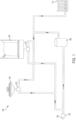
- the system 216 includes a smartphone 218A which acts as an active NFC device and a transponder 220 which acts as a passive NFC device.
- the transponder 220 is attached to a PCD comprising a hot water mixing valve 212 which, in operation, is connected to a residential water system and used to temper hot water for use in showers and faucets.
- the valve 212 includes a body 250 defining an interior passageway (not shown) connecting a hot water inlet 252, a cold water inlet 254, and a mixed water outlet 256.
- the inlets 252, 254 and outlet 256 are used to connect the valve 212 to the plumbing system.
- the valve also includes a manually adjustable handle 258 for adjusting the amounts of cold and hot water to be mixed and the temperature of the mixed water that exits the valve. During installation of the valve 212 in a plumbing system, or adjustment thereafter, a plumber will use the handle 258 to adjust water mixing and obtain the desired mixed water temperature.
- the valve 212 Within the interior of the valve 212, and in contact with the mixed water portion of the interior passageway of the valve 212 is at least one sensor 214 that is linked, for example via hardwire, to the transponder 220.
- An example of a sensor suitable for this application is an MS5837-30BA temperature and pressure sensor available from TE Connectivity Corporation.
- the sensor 214 which may extend through an opening in the body 250, is used to measure the temperature and pressure of the mixed water near the mixed water outlet 256. Additional sensors may also be placed in the inlet 254 and the outlet 256 to monitor inlet temperatures. And the sensors may comprise a temperature sensor, a pressure sensor, a flow rate sensor, etc., or combinations thereof.
- the valve 212 further includes a microcontroller 230 connected to the transponder 220 and the sensor 214
- transponder 220, the microcontroller 230 and the sensor 214 are shown assembled to the body 250, such that they are part of the valve 212, these components could be provided separate from the valve.
- the components 214, 230, 220 could be assembled to a short length of metal tubing that can be connected to the outlet 256 of the valve 212, by screw threads for example, and act as an optional accessory, which can be purchased with the valve.
- data 224A from the sensor 214 in this embodiment representing measured temperature and pressure of the mixed water within the valve 212 is returned to the smartphone 218A.
- the measured data 224A of pressure and temperature is symbolically represented by a gauge dial and a thermometer.
- a flow rate sensor could also be included in the valve 212.
- the sensor 214 can be maintained in an "off' position to conserve energy.
- the smartphone 218A also serves to power the sensor 214 to allow the sensor to collect the data 224A which the transponder 220 then provides to the smartphone 218A.
- the NFC connection can be used for data transmission only (as opposed to data transmission and power).
- a battery, or a switch connected to a power source can be activated once the active NFC device comes in range to provide power to the microcontroller 230 or sensors 214 as needed.
- An application on the smartphone 218A then collects and stores the data 224A. Further, the application creates a display on an output screen 226, using the stored data, to inform the user of the pressure and temperature of water within the valve 212.
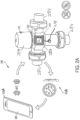
- FIG. 2B another simplified schematic overview of a system employing NFC in accordance with the present disclosure is shown generally at 316.
- the system 316 is similar to the system 216 so like reference numerals are used to refer to similar components. The following description is directed to the differences between the systems 216, 316.
- the system 316 includes a specialized controller 218B which acts as an active NFC device for interaction with the transponder 220.
- the transponder 220 is attached to a PCD comprising a pressure regulating valve 312.
- An example of a pressure regulating valve 312 is the Watts LF25AUB-Z3 pressure regulating valve.
- the valve 312 includes a body 350 defining an interior passageway (not shown) connecting a water inlet 352 and a water outlet 356.
- the inlet 352 and the outlet 356 are used to connect the valve 312 to the plumbing system.
- the valve 312 also includes a manually adjustable handle 358 for adjusting the pressure of the water that exits the outlet 356. During installation of the valve 312 in a plumbing system, or adjustment thereafter, a plumber will use the handle 358 to obtain the desired water pressure.
- a temperature and pressure sensor 214 that is linked, for example via hardwire, to the transponder 220.
- a suitable sensor is the MS5837-30BA temperature and pressure sensor available from TE Connectivity Corporation.
- the sensor 214 which may extend through a hole in the body 350, is used to measure the pressure of the water near the outlet 356. In this particular embodiment, only the pressure data produced by the sensor 214 is used. The temperature data is not used.
- An additional sensor may be placed in the inlet 352 to monitor inlet pressure.
- the specialized controller 218B When the specialized controller 218B is placed in close proximity (i.e., a few centimeters away) to the transponder 220, data 224B from the sensor 214 representing measured pressure of water from the valve 312 is passed to the specialized controller 218B.
- the data 224B of pressure data is symbolically represented by a gauge dial.
- the specialized controller 218B is adapted and configured to process the data and present information to the user on the display 226.
- the specialized controller 218B includes storage (e.g., memory such as RAM, ROM etc.) and processing capacity (e.g., a microprocessor) as needed.
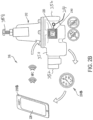
- the NFC system 400 includes a PCD 412, such as a valve, and a portable controller 418, such as a specialized control module, a mobile phone, tablet, laptop or the like.
- the NFC system 400 serves to generate a display on the portable controller 418 showing characteristics (i.e. temperature, pressure, flow rate) of water flowing through the PCD 412.
- the PCD 412 includes sensors 414 that measure the characteristics of the water to obtain measured data 415 (i.e. raw data).
- the PCD also includes an antenna board 420 and a microcontroller 430 operatively connected to the sensors 414, for example by being linked thereto via a wired connection.
- the PCD 412 includes a body 450 defining an interior passageway 452 connecting a water inlet 454 and a water outlet 456.
- the inlet 454 and the outlet 456 are used to connect the PCD 412 to a plumbing system.
- the PCD 412 also includes a manually adjustable handle 458 for adjusting the PCD so that characteristics of the water that exits the outlet 456 are controlled. During installation of the PCD 412 in a plumbing system, or adjustment thereafter, a plumber will use the handle 458 to obtain the desired water characteristic, such as temperature, pressure, or flow rate.
- the portable controller 418 acts as an active NFC device.
- the antenna board 420, the microcontroller 430, and the sensors 414 can act as passive NFC devices.
- the antenna board 420, microcontroller 430, and sensors 414 are typically in an "off' position until an active NFC device, such as the portable controller 418, is brought within close proximity.
- an active NFC device such as the portable controller 418
- the portable controller 418 is brought within close proximity to the passive NFC device (i.e. a passive NFC transponder)
- power is provided to the other components of the system 400.
- the antenna board 420 is serving as a passive NFC device for the system 400
- bringing the portable controller 418 within close proximity of the antenna board 420 allows the portable controller 418 to locate and provide power to the antenna board 420.
- the portable controller 418 has a power source 434 such as a battery to provide both power for the portable controller and passive NFC devices.
- the PCD 412 may also include a battery 460 connected through a normally open switch 462 to the microcontroller 430 and/or the sensors 414.
- the switch 462 is also connected to the antenna board 420 constructed to close, and create an electrical connection between the battery 460 and the sensors 414 and the microcontroller 430, upon receiving power from the antenna board 420.
- the antenna board 420 provides power to the switch whenever the portable controller 418 is brought within close proximity.
- the battery 460 can be used to supplement the wireless power provided by the portable controller 418. Since the battery 460 is only used when the portable controller 418 is brought within close proximity, it is anticipated that they battery should maintain power for an extended period, such as for the life of the PCD 412.
- the switch 462 may comprise a MOSFET, or other suitable transistor, that requires very little input current to control the battery 460.
- the antenna board 420 has a wired connection to the microcontroller 430, which in turn is wired to the sensors 414. In this way, the antenna board 420 is linked to the microcontroller 430 which is linked to the sensors 414. The portable controller 418 then transmits power to the antenna board 420 which transmits power 417 to the microcontroller 430 and sensors 414.
- the microcontroller 430 is not a separate and distinct component from the sensors 414, but rather, one or more microcontrollers 430 are included as a part of the sensors 414.
- the microcontroller 430 includes one or more processors 432 to perform logical operations and other necessary functions.
- the sensors 414 turn on and begin measuring characteristics of the water to obtain measured data 415.
- the sensors 414 can include a pressure sensor that takes readings of water pressure and a temperature sensor that takes temperature readings of the water.
- a pressure sensor that takes readings of water pressure
- a temperature sensor that takes temperature readings of the water.
- other types of sensors such as flowmeters may be used and various types of sensors capable of measuring data related to water and water flow, as are known in the art, may be employed for the present disclosure to be effective.
- the sensors 414 may include combination pressure, temperature, flow rate sensors, or the like, as desired.
- the fluid network is not for water but rather a network for a different fluid, which requires monitoring and adjustment.
- the sensors 414 have wireless capability such as the ability to communicate via a Bluetooth system. Therefore, after the sensors 414 obtain measured data 415, the sensors 414 can communicate directly with the portable controller 418, transferring the measured data 415 to the portable controller 418 for processing, storage, and display. In other cases, such as when the antenna board 420 is acting as a passive NFC device, the sensors 414 provide the measured data 415 to the microcontroller 430 which then processes the data to create a signal 419 which can be transmitted via NFC. The signal 419 is transmitted to the antenna board 420 which then transmits the signal 419, via NFC, to the mobile computer 418.
- the sensors 414 have wireless capability such as the ability to communicate via a Bluetooth system. Therefore, after the sensors 414 obtain measured data 415, the sensors 414 can communicate directly with the portable controller 418, transferring the measured data 415 to the portable controller 418 for processing, storage, and display. In other cases, such as when the antenna board 420 is acting as a passive NFC device, the sensors 414 provide
- the portable controller 418 further contains a processing module which converts the signal into letters, numbers, and other recognizable graphics to create a display for an output screen 421 of the portable controller 418.
- the portable controller 418 can be a smartphone and the processing module is an application on the smartphone.
- the application then generates a display for the output screen 421 using the signal 419 which helps the user quickly glean relevant information from the measured data 415.
- the application can generate a display indicating an approximate location of the relevant PCD 412 from which the measurements were taken, the time and/or date on which the measurements were taken, and values associated with the measured data 415 (i.e., the temperature or pressure of the water).
- the portable controller 418 can then store the data for future access such as in an internal memory bank. Additionally, or alternatively, the portable controller 418 can be configured to upload the data to a remote location, such as a computing network or cloud 423, where the data can be stored and/or further analyzed. It is anticipated that other information may be collected from the system, including the model and serial numbers of the PCD, the location of the PCD, and the name of the installer, for example. Such information can, in turn, be used to register the PCD for warranty coverage and notify the owner of any product recalls, for example. The system may also be used to download information, such as assembly drawings and installation instructions, from the cloud 423 to the controller 418.
- a remote location such as a computing network or cloud 423
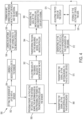
- a flowchart showing a method 550 of remotely measuring characteristics of water passing through a PCD is shown.
- the method 550 can be carried out in a plumbing system using PCDs and the other components discussed above and shown in Figs. 1 - 3 , for example.
- the method 550 begins, at step 552, with the step of fitting the interior of a PCD with a sensor.
- the sensor is placed within the interior of a PCD within a water pipe.
- a microcontroller is then linked to the sensor at step 554.
- an antenna board having passive NFC capabilities is linked to the microcontroller.
- the microcontroller is capable of processing data and transmitting signals and power between the sensor and the antenna board.
- an active NFC device locates the antenna board using NFC technology and establishes a connection with the antenna board.
- the active NFC device provides power to the antenna board. This allows the antenna board to provide power to the microcontroller and the sensor, turning the microcontroller and sensor "on.” Having been turned on, the sensor begins collecting data related to water within the PCD at step 562. As the measured data is collected, the data is transferred, at step 564, to the microcontroller.
- the microcontroller processes the data and coverts the data into a signal which can be used to more easily transmit the data.
- the signal is then transmitted, by the microcontroller, to the antenna board at step 568.
- the antenna board transmits the signal to the active NFC device.
- the signal represents the data collected by the measurement device related to water within the PCD.
- the signal can contain information regarding characteristics of the water such as temperature, pressure, flow rate, or the time and location that the measurements were taken. Therefore after receiving the signal, the active NFC device can generate a display which depicts the data in a user friendly setting at step 572.
- the active NFC device is a specialized device and the display is generated on an output screen by an application on the specialized device.
- the display provides a quick and effective means to analyze the water within the PCD which can then be used for various purposes.
- the display can be relied upon to effectively operate and adjust a residential water system 100 (See Fig. 1 ).
- the information shown on the display can be used to adjust the valves of the residential water system 100.
- the PCD 212 that is proximate to the sink 104 could be linked to an antenna board which serves as a passive NFC device and a microcontroller.
- the PCD 212 is powered on and begins taking one or more pressure readings of the water in accordance with the steps of the method 550 described above.
- the user looks at the final display on their smartphone to see the measured characteristics of the water at that location. For example, if the PCD 212 included a pressure sensor, the display might show pressure of the water at that location.
- the user can make an adjustment to the corresponding PCD 212, throttling or opening the PCD 212 to allow more or less water through the cold water line and to the sink 104 as desired, for example.
- the user may adjust the flow of fluid through the PCD 212 using a manual or other adjustment mechanism of the PCD 212 if a parameter is not equal to a desired characteristic.
- the parameter may be set to an desired value with a specified range.
- the data can be stored in memory for later access.
- the stored data can also be uploaded to a cloud storage location.
- Steps 558 through 572 can then be repeated, as desired, with respect to the other PCDs 212, 312 within the system 100.
- steps 574 and 576 may also be carried out after, or just before, step 572.
Landscapes
- Engineering & Computer Science (AREA)
- Physics & Mathematics (AREA)
- General Physics & Mathematics (AREA)
- Theoretical Computer Science (AREA)
- General Engineering & Computer Science (AREA)
- Computer Networks & Wireless Communication (AREA)
- Signal Processing (AREA)
- Fluid Mechanics (AREA)
- Automation & Control Theory (AREA)
- Arrangements For Transmission Of Measured Signals (AREA)
- Measuring Volume Flow (AREA)
- Details Of Flowmeters (AREA)
Claims (11)
- System zur Fernmessung der Eigenschaften von Wasser, das durch eine Rohrleitungskontrollvorrichtung ("PCD") fließt, umfassend:eine Rohrleitungskontrollvorrichtung ("PCD") (212, 312, 412);einen Sensor (214, 414) in einem Innenraum der PCD, der so konfiguriert ist, dass er mindestens eine Eigenschaft des Wassers misst, um Messdaten zu erhalten, wobei der Sensor mit einem Mikrocontroller (230, 430) der PCD verbunden ist;wobei das System dadurch gekennzeichnet ist, dass es außerdem umfasst eine Antennenplatine (220, 420), die mit dem Mikrocontroller (230, 430) und dem Sensor (214, 414) verbunden ist, wobei die Antennenplatine (220, 430) so konfiguriert ist, dass sie Energie an den Mikrocontroller (230, 430) und den Sensor (214, 414) überträgt, so dass eine dedizierte Energiequelle, die mit dem Sensor und dem Mikrocontroller verbunden ist, nicht erforderlich ist; undeine von der PCD (212, 312, 412) getrennte mobile Vorrichtung (218A, 218B, 418), die so konfiguriert ist, dass sie die Antennenplatine (220, 430) drahtlos mit Strom versorgt, um den Strom an den Mikrocontroller (230, 430) und den Sensor (214, 414) zu übertragen,wobei der Mikrocontroller (230, 430) und der Sensor (214, 414) ausgeschaltet sind, wenn kein Strom von der Antennenplatine (220, 420) übertragen wird, undwobei die mobile Vorrichtung (218A, 218B, 418) eine spezialisierte mobile Vorrichtung ist, die Folgendes umfasst,einen aktiven NFC (Near Field Communication)-Transponder,einen Bildschirm (226, 421),einen Mikrocontroller, der betriebsmäßig mit dem aktiven NFC-Transponder und dem Bildschirm verbunden ist, undein Computerprogramm, das auf den Mikrocontroller geladen und so konfiguriert ist, dass es bei Aktivierung durch einen Benutzer:den aktiven NFC-Transponder anweist, einen nahegelegenen passiven NFC-Transponder zu lokalisieren, eine drahtlose Datenverbindung mit dem passiven NFC-Transponder herzustellen, drahtlos Energie an den passiven NFC-Transponder zu übertragen und drahtlos Messdaten von dem passiven NFC-Transponder zu empfangen, unddie gemessenen Daten auf dem Bildschirm (226, 421) anzeigt;wobei die PCD enthält,einen Körper (250, 350, 450) mit mindestens einem Einlass (252, 254, 352) und einem Auslass (256, 356) zum Anschluss an ein Rohrleitungssystem und einem Durchgang (452), der sich zwischen dem Einlass und dem Auslass erstreckt, damit Fluid durch die PCD fließen kann,mindestens einen manuellen Einstellmechanismus (258, 358, 458), der mit dem Körper gekoppelt ist, um den Durchfluss von Fluid durch den Durchgang (452) zu steuern;der Sensor ein stromloser Sensor (214, 414) ist, der so konfiguriert ist, dass er mindestens eine Eigenschaft des durch den PCD fließenden Fluids misst, um die gemessenen Daten zu erhalten, wenn der stromlose Sensor Strom erhält, undwobei die Antennenplatine als passiver NFC-Transponder (220, 420) dient, der operativ mit dem Sensor (214, 414) verbunden und so konfiguriert ist, dass er,eine drahtlose Datenverbindung mit dem aktiven NFC-Transponder des mobilen Geräts (218A, 218B, 418) herstellt, wenn es von dem aktiven NFC-Transponder geortet wird,drahtlos Strom von dem aktiven NFC-Transponder erhält,zumindest einen Teil der drahtlos empfangenen Leistung an den Sensor (214, 414) zu überträgt,die Messdaten vom Sensor (214, 414) empfängt, unddie gemessenen Daten drahtlos an den aktiven NFC-Transponder überträgt;wobei die PCD in ein Rohrleitungssystem eingebaut wird, indem der mindestens eine Einlass und der mindestens eine Auslass mit dem Rohrleitungssystem verbunden werden und Fluid aus dem Rohrleitungssystem durch den Durchgang des PCD fließen kann;wobei das Computerprogramm der mobilen Vorrichtung aktiviert wird, wenn die mobile Vorrichtung in der Nähe der PCD platziert wird und die gemessenen Daten vom Anzeigebildschirm der mobilen Vorrichtung gelesen werden; undwobei der Durchfluss des Fluids durch die PCD unter Verwendung des manuellen Einstellmechanismus der PCD eingestellt wird, wenn die gemessenen Daten vom Anzeigebildschirm anzeigen, dass die gemessene Eigenschaft des Fluids nicht gleich einer gewünschten Eigenschaft ist.
- System gemäß Anspruch 1, wobei:der Sensor (214, 414) drahtlose Kommunikationsfähigkeiten aufweist und so konfiguriert ist, dass er die gemessenen Daten drahtlos an das mobile Gerät (218A, 218B, 418) überträgt; unddas mobile Gerät (218A, 218B, 418) so konfiguriert ist, dass es die von dem Sensor (214, 414) empfangenen Messdaten verarbeitet.
- System gemäß Anspruch 1, wobei:der Sensor (214, 414) so konfiguriert ist, dass er die gemessenen Daten an den Mikrocontroller (230, 430) übermittelt; undder Mikrocontroller (230, 430) so konfiguriert ist, dass er die Messdaten verarbeitet, bevor er die verarbeiteten Messdaten an das mobile Gerät (218A, 218B, 418) sendet.
- System gemäß Anspruch 3, wobei:die mobile Vorrichtung (218A, 218B, 418) so konfiguriert ist, dass sie die Antennenplatine (220, 420) drahtlos ortet und die Leistung an die Antennenplatine (220; 420) überträgt; unddie Antennenplatine (220, 420) ist ein passiver NFC-Transponder (220, 420).
- System gemäß Anspruch 4, wobei das mobile Gerät (218A, 218B, 418) ein aktives NFC-Gerät ist, das so konfiguriert ist, dass es Messdaten von dem passiven NFC-Transponder (220, 420) empfängt.
- System gemäß Anspruch 2, wobei das mobile Gerät (218A, 218B, 418) ferner so konfiguriert ist, dass es: die verarbeiteten Messdaten speichert; und eine Ausgabeanzeige basierend auf den verarbeiteten Messdaten erzeugt.
- System gemäß Anspruch 2, wobei das mobile Gerät ein spezialisiertes Gerät (218B) mit einem Prozessor und einem mit dem Prozessor operativ verbundenen Speicher ist.
- System gemäß Anspruch 6, wobei:das mobile Gerät (218A, 418) ein Smartphone mit einer mobilen Softwareanwendung ist; wobei die mobile Softwareanwendung konfiguriert ist, dass siedie gemessenen Daten verarbeitet unddie verarbeiteten Messdaten anzeigt und speichert.
- System gemäß Anspruch 1, bei dem der Sensor (215) so konfiguriert ist, dass er mindestens einen Parameter misst, der aus der Gruppe ausgewählt ist, die aus folgenden Parametern besteht: Wassertemperatur, Wasserdruck, Wasserdurchflussmenge durch die PCD (212312) und Kombinationen davon.
- System gemäß Anspruch 1, ferner umfassend:eine Batterie (460) innerhalb der PCD (412), die mit dem Mikrocontroller (430) und dem Sensor (414) über einen Schalter (462) verbunden ist, wobei der Schalter so konfiguriert ist, dass er geschlossen ist und eine elektrische Verbindung zwischen der Batterie und dem Mikrocontroller und dem Sensor herstellt, wenn Strom an den Schalter angelegt wird; undwobei die Antennenplatine so konfiguriert ist, dass sie den Schalter mit Strom versorgt, wenn die Antennenplatine Strom von dem mobilen Gerät empfängt.
- System gemäß Anspruch 1 ferner umfassend:eine Batterie (460); undeinen Schalter (462), der die Batterie (460) mit dem Sensor (414) verbindet, wobei der Schalter (462) so konfiguriert ist, dass er geschlossen wird und eine elektrische Verbindung zwischen der Batterie und dem Sensor herstellt, wenn Strom an den Schalter angelegt wird;wobei der passive NFC-Transponder (420) so konfiguriert ist, dass er den Schalter (462) mit Strom versorgt, wenn der passive NFC-Transponder drahtlos Strom von dem aktiven NFC-Transponder empfängt.
Applications Claiming Priority (2)
| Application Number | Priority Date | Filing Date | Title |
|---|---|---|---|
| US201762539155P | 2017-07-31 | 2017-07-31 | |
| PCT/US2018/043673 WO2019027762A1 (en) | 2017-07-31 | 2018-07-25 | PLUMBING CONTROL DEVICE |
Publications (3)
| Publication Number | Publication Date |
|---|---|
| EP3662344A1 EP3662344A1 (de) | 2020-06-10 |
| EP3662344A4 EP3662344A4 (de) | 2021-06-16 |
| EP3662344B1 true EP3662344B1 (de) | 2024-10-02 |
Family
ID=65234134
Family Applications (1)
| Application Number | Title | Priority Date | Filing Date |
|---|---|---|---|
| EP18841642.4A Active EP3662344B1 (de) | 2017-07-31 | 2018-07-25 | Sanitärsteuerungssystem |
Country Status (4)
| Country | Link |
|---|---|
| US (3) | US11543278B2 (de) |
| EP (1) | EP3662344B1 (de) |
| CN (1) | CN212623758U (de) |
| WO (1) | WO2019027762A1 (de) |
Families Citing this family (9)
| Publication number | Priority date | Publication date | Assignee | Title |
|---|---|---|---|---|
| GB201906785D0 (en) * | 2019-05-14 | 2019-06-26 | Smartvalve Ltd | Fluid flow control system |
| US12301661B2 (en) | 2019-12-06 | 2025-05-13 | Zurn Water, Llc | Water management system and user interface |
| WO2021252008A1 (en) | 2020-06-08 | 2021-12-16 | Zurn Industries, Llc | Cloud-connected occupancy lights and status indication |
| US11108865B1 (en) * | 2020-07-27 | 2021-08-31 | Zurn Industries, Llc | Battery powered end point device for IoT applications |
| US11153945B1 (en) | 2020-12-14 | 2021-10-19 | Zurn Industries, Llc | Facility occupancy detection with thermal grid sensor |
| US11594119B2 (en) | 2021-05-21 | 2023-02-28 | Zurn Industries, Llc | System and method for providing a connection status of a battery powered end point device |
| US11543791B1 (en) | 2022-02-10 | 2023-01-03 | Zurn Industries, Llc | Determining operations for a smart fixture based on an area status |
| US11514679B1 (en) | 2022-02-18 | 2022-11-29 | Zurn Industries, Llc | Smart method for noise rejection in spatial human detection systems for a cloud connected occupancy sensing network |
| US11555734B1 (en) | 2022-02-18 | 2023-01-17 | Zurn Industries, Llc | Smart and cloud connected detection mechanism and real-time internet of things (IoT) system management |
Family Cites Families (23)
| Publication number | Priority date | Publication date | Assignee | Title |
|---|---|---|---|---|
| US5333785A (en) * | 1991-12-19 | 1994-08-02 | Dodds Graeme C | Wireless irrigation system |
| US5745049A (en) | 1995-07-20 | 1998-04-28 | Yokogawa Electric Corporation | Wireless equipment diagnosis system |
| US7380210B2 (en) | 2001-07-20 | 2008-05-27 | Siemens Building Technologies, Inc. | User interface with installment mode |
| US6907300B2 (en) | 2001-07-20 | 2005-06-14 | Siemens Building Technologies, Inc. | User interface for fire detection system |
| US7788970B2 (en) * | 2002-10-28 | 2010-09-07 | Digital Sun, Inc. | Wireless sensor probe |
| US20050087235A1 (en) | 2003-10-22 | 2005-04-28 | Skorpik James R. | Sensor assembly, system including RFID sensor assemblies, and method |
| US7148803B2 (en) | 2003-10-24 | 2006-12-12 | Symbol Technologies, Inc. | Radio frequency identification (RFID) based sensor networks |
| WO2006004985A1 (en) * | 2004-06-30 | 2006-01-12 | Great Stuff, Inc. | Low power system for wireless monitoring of an environment and irrigation control |
| WO2007011999A2 (en) * | 2005-07-19 | 2007-01-25 | Rain Bird Corporation | Wireless extension to an irrigation control system and related methods |
| CA2628301C (en) * | 2007-04-09 | 2014-06-10 | Masco Corporation Of Indiana | Wireless power transfer device for a fluid delivery apparatus |
| US20080281163A1 (en) | 2007-05-10 | 2008-11-13 | General Electric Company | Apparatus and method for acquiring medical data |
| TWI495221B (zh) * | 2008-07-09 | 2015-08-01 | 通路實業集團國際公司 | 無線充電系統及其遠方裝置與方法 |
| TR200805998A2 (tr) * | 2008-08-12 | 2009-12-21 | Kodalfa B�Lg� Ve �Let���M Teknoloj�Ler� Sanay� Ve T�Caret A.�. | Seralar için uzaktan kablosuz iklim gözlemleme ve kontrol sistemi |
| CN102197716B (zh) | 2008-08-21 | 2014-12-03 | 西门子工业公司 | 带有安装板的建筑物自动化系统的输入/输出模块 |
| US8678346B2 (en) * | 2011-06-06 | 2014-03-25 | Automatic Switch Company | Near-field wireless powered solenoid valve |
| US9201416B2 (en) | 2012-01-24 | 2015-12-01 | Fisher Controls International Llc | Asset data modules including an integral near field communication interface |
| US9523971B2 (en) | 2012-11-07 | 2016-12-20 | Hcl Technologies Ltd. | Monitoring and controlling of valves in industrial process control and automation using NFC |
| CH707624A1 (de) | 2013-02-28 | 2014-08-29 | Belimo Holding Ag | Steuervorrichtung, Komponenten und mobile Servicevorrichtung für eine HVAC-Anlage. |
| GB2519120B (en) * | 2013-10-10 | 2017-10-18 | Abb Ltd | Methods and apparatus relating to measurement instruments |
| JP6381305B2 (ja) * | 2014-06-10 | 2018-08-29 | キヤノン株式会社 | 電子機器 |
| US9645584B2 (en) * | 2014-09-17 | 2017-05-09 | Honeywell International Inc. | Gas valve with electronic health monitoring |
| US11041839B2 (en) * | 2015-06-05 | 2021-06-22 | Mueller International, Llc | Distribution system monitoring |
| US11503782B2 (en) * | 2018-04-11 | 2022-11-22 | Rain Bird Corporation | Smart drip irrigation emitter |
-
2018
- 2018-07-25 EP EP18841642.4A patent/EP3662344B1/de active Active
- 2018-07-25 CN CN201890001159.7U patent/CN212623758U/zh active Active
- 2018-07-25 US US16/634,498 patent/US11543278B2/en active Active
- 2018-07-25 WO PCT/US2018/043673 patent/WO2019027762A1/en not_active Ceased
-
2022
- 2022-12-12 US US18/079,108 patent/US12135230B2/en active Active
-
2024
- 2024-10-25 US US18/927,185 patent/US20250052602A1/en active Pending
Also Published As
| Publication number | Publication date |
|---|---|
| US11543278B2 (en) | 2023-01-03 |
| US20200232832A1 (en) | 2020-07-23 |
| WO2019027762A1 (en) | 2019-02-07 |
| CN212623758U (zh) | 2021-02-26 |
| US20230116158A1 (en) | 2023-04-13 |
| EP3662344A1 (de) | 2020-06-10 |
| EP3662344A4 (de) | 2021-06-16 |
| US20250052602A1 (en) | 2025-02-13 |
| US12135230B2 (en) | 2024-11-05 |
Similar Documents
| Publication | Publication Date | Title |
|---|---|---|
| EP3662344B1 (de) | Sanitärsteuerungssystem | |
| EP3243080B1 (de) | Durchflussdetektionsvorrichtung | |
| US10527516B2 (en) | Passive leak detection for building water supply | |
| KR101853325B1 (ko) | 사물 인터넷을 이용한 자동제어 밸브 시스템 | |
| US20160356026A1 (en) | Rf-signal-emitting valve for flow monitoring and leak detection | |
| GB2452311A (en) | A temperature monitoring device and a method of monitoring temperature using such a device | |
| US9857803B1 (en) | Water conservation system | |
| US20170335550A1 (en) | Interactive Water Monitoring System | |
| US20170318761A1 (en) | Water flow management systems and methods | |
| EP3008367B1 (de) | Kombiniertes trenn- und rückschlagventil mit integrierter durchflussraten-, druck- und/oder temperaturmessung | |
| GB2478124A (en) | Water Sanitary Management System | |
| US11149864B2 (en) | Smart monocontrol cartridge for taps, smart monocontrol taps, smart management system and method for monocontrol taps | |
| CN102635894A (zh) | 供暖系统平衡控制方法及诊断测量装置 | |
| CN105917279A (zh) | 过程自动化现场装置 | |
| WO2015154135A1 (en) | A system, apparatus and method for controlling water flow | |
| CN106052142B (zh) | 具有回水功能的热水器系统及其控制方法 | |
| CN101762019A (zh) | 一种可自动调节温度的出水装置 | |
| KR20200064383A (ko) | 밴드형 수압센서를 이용한 수량측정장치 및 이를 이용한 물사용정보 제공시스템 | |
| CN106662565A (zh) | 在流体的输送点处的智能测量系统 | |
| EP2442038A2 (de) | Integrierte Vorrichtung zur Erfassung der von Heizkörpern abgegebenene Wärme und zum Steuern eines Thermostatventils | |
| CN204062503U (zh) | 一种带给排水测量仪的智能无线控制器及其管道系统 | |
| US20170122634A1 (en) | Methods for operating heat pump water heater appliances | |
| AU2017100989A4 (en) | Flow detection device | |
| US20100321670A1 (en) | Apparatus for measuring the displacement of a valve rod of a motor-operated valve and transmitting a related signal | |
| CN105581652A (zh) | 一种eos控温控流量的饮用水供水设备及系统 |
Legal Events
| Date | Code | Title | Description |
|---|---|---|---|
| STAA | Information on the status of an ep patent application or granted ep patent |
Free format text: STATUS: THE INTERNATIONAL PUBLICATION HAS BEEN MADE |
|
| PUAI | Public reference made under article 153(3) epc to a published international application that has entered the european phase |
Free format text: ORIGINAL CODE: 0009012 |
|
| STAA | Information on the status of an ep patent application or granted ep patent |
Free format text: STATUS: REQUEST FOR EXAMINATION WAS MADE |
|
| 17P | Request for examination filed |
Effective date: 20200129 |
|
| AK | Designated contracting states |
Kind code of ref document: A1 Designated state(s): AL AT BE BG CH CY CZ DE DK EE ES FI FR GB GR HR HU IE IS IT LI LT LU LV MC MK MT NL NO PL PT RO RS SE SI SK SM TR |
|
| AX | Request for extension of the european patent |
Extension state: BA ME |
|
| DAV | Request for validation of the european patent (deleted) | ||
| DAX | Request for extension of the european patent (deleted) | ||
| RIC1 | Information provided on ipc code assigned before grant |
Ipc: G05D 16/20 20060101ALI20210219BHEP Ipc: G05D 7/06 20060101AFI20210219BHEP Ipc: G05D 23/19 20060101ALI20210219BHEP Ipc: G05B 19/042 20060101ALI20210219BHEP |
|
| A4 | Supplementary search report drawn up and despatched |
Effective date: 20210518 |
|
| RIC1 | Information provided on ipc code assigned before grant |
Ipc: G05D 7/06 20060101AFI20210511BHEP Ipc: G05D 16/20 20060101ALI20210511BHEP Ipc: G05D 23/19 20060101ALI20210511BHEP Ipc: G05B 19/042 20060101ALI20210511BHEP Ipc: H04B 5/00 20060101ALI20210511BHEP |
|
| STAA | Information on the status of an ep patent application or granted ep patent |
Free format text: STATUS: EXAMINATION IS IN PROGRESS |
|
| 17Q | First examination report despatched |
Effective date: 20220408 |
|
| P01 | Opt-out of the competence of the unified patent court (upc) registered |
Effective date: 20230526 |
|
| GRAP | Despatch of communication of intention to grant a patent |
Free format text: ORIGINAL CODE: EPIDOSNIGR1 |
|
| STAA | Information on the status of an ep patent application or granted ep patent |
Free format text: STATUS: GRANT OF PATENT IS INTENDED |
|
| INTG | Intention to grant announced |
Effective date: 20240515 |
|
| GRAS | Grant fee paid |
Free format text: ORIGINAL CODE: EPIDOSNIGR3 |
|
| GRAA | (expected) grant |
Free format text: ORIGINAL CODE: 0009210 |
|
| STAA | Information on the status of an ep patent application or granted ep patent |
Free format text: STATUS: THE PATENT HAS BEEN GRANTED |
|
| AK | Designated contracting states |
Kind code of ref document: B1 Designated state(s): AL AT BE BG CH CY CZ DE DK EE ES FI FR GB GR HR HU IE IS IT LI LT LU LV MC MK MT NL NO PL PT RO RS SE SI SK SM TR |
|
| REG | Reference to a national code |
Ref country code: GB Ref legal event code: FG4D |
|
| REG | Reference to a national code |
Ref country code: CH Ref legal event code: EP |
|
| REG | Reference to a national code |
Ref country code: IE Ref legal event code: FG4D |
|
| REG | Reference to a national code |
Ref country code: DE Ref legal event code: R096 Ref document number: 602018075020 Country of ref document: DE |
|
| REG | Reference to a national code |
Ref country code: LT Ref legal event code: MG9D |
|
| REG | Reference to a national code |
Ref country code: NL Ref legal event code: MP Effective date: 20241002 |
|
| REG | Reference to a national code |
Ref country code: AT Ref legal event code: MK05 Ref document number: 1728939 Country of ref document: AT Kind code of ref document: T Effective date: 20241002 |
|
| PG25 | Lapsed in a contracting state [announced via postgrant information from national office to epo] |
Ref country code: NL Free format text: LAPSE BECAUSE OF FAILURE TO SUBMIT A TRANSLATION OF THE DESCRIPTION OR TO PAY THE FEE WITHIN THE PRESCRIBED TIME-LIMIT Effective date: 20241002 |
|
| PG25 | Lapsed in a contracting state [announced via postgrant information from national office to epo] |
Ref country code: NL Free format text: LAPSE BECAUSE OF FAILURE TO SUBMIT A TRANSLATION OF THE DESCRIPTION OR TO PAY THE FEE WITHIN THE PRESCRIBED TIME-LIMIT Effective date: 20241002 |
|
| PG25 | Lapsed in a contracting state [announced via postgrant information from national office to epo] |
Ref country code: IS Free format text: LAPSE BECAUSE OF FAILURE TO SUBMIT A TRANSLATION OF THE DESCRIPTION OR TO PAY THE FEE WITHIN THE PRESCRIBED TIME-LIMIT Effective date: 20250202 Ref country code: HR Free format text: LAPSE BECAUSE OF FAILURE TO SUBMIT A TRANSLATION OF THE DESCRIPTION OR TO PAY THE FEE WITHIN THE PRESCRIBED TIME-LIMIT Effective date: 20241002 Ref country code: PT Free format text: LAPSE BECAUSE OF FAILURE TO SUBMIT A TRANSLATION OF THE DESCRIPTION OR TO PAY THE FEE WITHIN THE PRESCRIBED TIME-LIMIT Effective date: 20250203 |
|
| PG25 | Lapsed in a contracting state [announced via postgrant information from national office to epo] |
Ref country code: FI Free format text: LAPSE BECAUSE OF FAILURE TO SUBMIT A TRANSLATION OF THE DESCRIPTION OR TO PAY THE FEE WITHIN THE PRESCRIBED TIME-LIMIT Effective date: 20241002 |
|
| PG25 | Lapsed in a contracting state [announced via postgrant information from national office to epo] |
Ref country code: BG Free format text: LAPSE BECAUSE OF FAILURE TO SUBMIT A TRANSLATION OF THE DESCRIPTION OR TO PAY THE FEE WITHIN THE PRESCRIBED TIME-LIMIT Effective date: 20241002 |
|
| PG25 | Lapsed in a contracting state [announced via postgrant information from national office to epo] |
Ref country code: ES Free format text: LAPSE BECAUSE OF FAILURE TO SUBMIT A TRANSLATION OF THE DESCRIPTION OR TO PAY THE FEE WITHIN THE PRESCRIBED TIME-LIMIT Effective date: 20241002 |
|
| PG25 | Lapsed in a contracting state [announced via postgrant information from national office to epo] |
Ref country code: NO Free format text: LAPSE BECAUSE OF FAILURE TO SUBMIT A TRANSLATION OF THE DESCRIPTION OR TO PAY THE FEE WITHIN THE PRESCRIBED TIME-LIMIT Effective date: 20250102 |
|
| PG25 | Lapsed in a contracting state [announced via postgrant information from national office to epo] |
Ref country code: AT Free format text: LAPSE BECAUSE OF FAILURE TO SUBMIT A TRANSLATION OF THE DESCRIPTION OR TO PAY THE FEE WITHIN THE PRESCRIBED TIME-LIMIT Effective date: 20241002 Ref country code: LV Free format text: LAPSE BECAUSE OF FAILURE TO SUBMIT A TRANSLATION OF THE DESCRIPTION OR TO PAY THE FEE WITHIN THE PRESCRIBED TIME-LIMIT Effective date: 20241002 Ref country code: GR Free format text: LAPSE BECAUSE OF FAILURE TO SUBMIT A TRANSLATION OF THE DESCRIPTION OR TO PAY THE FEE WITHIN THE PRESCRIBED TIME-LIMIT Effective date: 20250103 |
|
| PG25 | Lapsed in a contracting state [announced via postgrant information from national office to epo] |
Ref country code: CZ Free format text: LAPSE BECAUSE OF FAILURE TO SUBMIT A TRANSLATION OF THE DESCRIPTION OR TO PAY THE FEE WITHIN THE PRESCRIBED TIME-LIMIT Effective date: 20241002 Ref country code: PL Free format text: LAPSE BECAUSE OF FAILURE TO SUBMIT A TRANSLATION OF THE DESCRIPTION OR TO PAY THE FEE WITHIN THE PRESCRIBED TIME-LIMIT Effective date: 20241002 |
|
| PG25 | Lapsed in a contracting state [announced via postgrant information from national office to epo] |
Ref country code: RS Free format text: LAPSE BECAUSE OF FAILURE TO SUBMIT A TRANSLATION OF THE DESCRIPTION OR TO PAY THE FEE WITHIN THE PRESCRIBED TIME-LIMIT Effective date: 20250102 |
|
| PG25 | Lapsed in a contracting state [announced via postgrant information from national office to epo] |
Ref country code: SM Free format text: LAPSE BECAUSE OF FAILURE TO SUBMIT A TRANSLATION OF THE DESCRIPTION OR TO PAY THE FEE WITHIN THE PRESCRIBED TIME-LIMIT Effective date: 20241002 |
|
| REG | Reference to a national code |
Ref country code: DE Ref legal event code: R097 Ref document number: 602018075020 Country of ref document: DE |
|
| PG25 | Lapsed in a contracting state [announced via postgrant information from national office to epo] |
Ref country code: DK Free format text: LAPSE BECAUSE OF FAILURE TO SUBMIT A TRANSLATION OF THE DESCRIPTION OR TO PAY THE FEE WITHIN THE PRESCRIBED TIME-LIMIT Effective date: 20241002 |
|
| PG25 | Lapsed in a contracting state [announced via postgrant information from national office to epo] |
Ref country code: EE Free format text: LAPSE BECAUSE OF FAILURE TO SUBMIT A TRANSLATION OF THE DESCRIPTION OR TO PAY THE FEE WITHIN THE PRESCRIBED TIME-LIMIT Effective date: 20241002 |
|
| PG25 | Lapsed in a contracting state [announced via postgrant information from national office to epo] |
Ref country code: RO Free format text: LAPSE BECAUSE OF FAILURE TO SUBMIT A TRANSLATION OF THE DESCRIPTION OR TO PAY THE FEE WITHIN THE PRESCRIBED TIME-LIMIT Effective date: 20241002 |
|
| PG25 | Lapsed in a contracting state [announced via postgrant information from national office to epo] |
Ref country code: SK Free format text: LAPSE BECAUSE OF FAILURE TO SUBMIT A TRANSLATION OF THE DESCRIPTION OR TO PAY THE FEE WITHIN THE PRESCRIBED TIME-LIMIT Effective date: 20241002 |
|
| PG25 | Lapsed in a contracting state [announced via postgrant information from national office to epo] |
Ref country code: IT Free format text: LAPSE BECAUSE OF FAILURE TO SUBMIT A TRANSLATION OF THE DESCRIPTION OR TO PAY THE FEE WITHIN THE PRESCRIBED TIME-LIMIT Effective date: 20241002 |
|
| PLBE | No opposition filed within time limit |
Free format text: ORIGINAL CODE: 0009261 |
|
| STAA | Information on the status of an ep patent application or granted ep patent |
Free format text: STATUS: NO OPPOSITION FILED WITHIN TIME LIMIT |
|
| PG25 | Lapsed in a contracting state [announced via postgrant information from national office to epo] |
Ref country code: SE Free format text: LAPSE BECAUSE OF FAILURE TO SUBMIT A TRANSLATION OF THE DESCRIPTION OR TO PAY THE FEE WITHIN THE PRESCRIBED TIME-LIMIT Effective date: 20241002 |
|
| 26N | No opposition filed |
Effective date: 20250703 |
|
| PGFP | Annual fee paid to national office [announced via postgrant information from national office to epo] |
Ref country code: DE Payment date: 20250729 Year of fee payment: 8 |
|
| PGFP | Annual fee paid to national office [announced via postgrant information from national office to epo] |
Ref country code: FR Payment date: 20250725 Year of fee payment: 8 |
|
| REG | Reference to a national code |
Ref country code: CH Ref legal event code: H13 Free format text: ST27 STATUS EVENT CODE: U-0-0-H10-H13 (AS PROVIDED BY THE NATIONAL OFFICE) Effective date: 20260224 |
|
| PG25 | Lapsed in a contracting state [announced via postgrant information from national office to epo] |
Ref country code: LU Free format text: LAPSE BECAUSE OF NON-PAYMENT OF DUE FEES Effective date: 20250725 |
|
| GBPC | Gb: european patent ceased through non-payment of renewal fee |
Effective date: 20250725 |