EP3662278B1 - System, method and computer program product for gas analysis - Google Patents
System, method and computer program product for gas analysis Download PDFInfo
- Publication number
- EP3662278B1 EP3662278B1 EP19748382.9A EP19748382A EP3662278B1 EP 3662278 B1 EP3662278 B1 EP 3662278B1 EP 19748382 A EP19748382 A EP 19748382A EP 3662278 B1 EP3662278 B1 EP 3662278B1
- Authority
- EP
- European Patent Office
- Prior art keywords
- gas
- average
- target
- attenuation
- sensor
- Prior art date
- Legal status (The legal status is an assumption and is not a legal conclusion. Google has not performed a legal analysis and makes no representation as to the accuracy of the status listed.)
- Active
Links
Images







Classifications
-
- G—PHYSICS
- G01—MEASURING; TESTING
- G01N—INVESTIGATING OR ANALYSING MATERIALS BY DETERMINING THEIR CHEMICAL OR PHYSICAL PROPERTIES
- G01N29/00—Investigating or analysing materials by the use of ultrasonic, sonic or infrasonic waves; Visualisation of the interior of objects by transmitting ultrasonic or sonic waves through the object
- G01N29/22—Details, e.g. general constructional or apparatus details
- G01N29/24—Probes
- G01N29/2462—Probes with waveguides, e.g. SAW devices
-
- G—PHYSICS
- G01—MEASURING; TESTING
- G01N—INVESTIGATING OR ANALYSING MATERIALS BY DETERMINING THEIR CHEMICAL OR PHYSICAL PROPERTIES
- G01N29/00—Investigating or analysing materials by the use of ultrasonic, sonic or infrasonic waves; Visualisation of the interior of objects by transmitting ultrasonic or sonic waves through the object
- G01N29/02—Analysing fluids
- G01N29/022—Fluid sensors based on microsensors, e.g. quartz crystal-microbalance [QCM], surface acoustic wave [SAW] devices, tuning forks, cantilevers, flexural plate wave [FPW] devices
-
- G—PHYSICS
- G01—MEASURING; TESTING
- G01N—INVESTIGATING OR ANALYSING MATERIALS BY DETERMINING THEIR CHEMICAL OR PHYSICAL PROPERTIES
- G01N29/00—Investigating or analysing materials by the use of ultrasonic, sonic or infrasonic waves; Visualisation of the interior of objects by transmitting ultrasonic or sonic waves through the object
- G01N29/02—Analysing fluids
- G01N29/032—Analysing fluids by measuring attenuation of acoustic waves
-
- G—PHYSICS
- G01—MEASURING; TESTING
- G01N—INVESTIGATING OR ANALYSING MATERIALS BY DETERMINING THEIR CHEMICAL OR PHYSICAL PROPERTIES
- G01N29/00—Investigating or analysing materials by the use of ultrasonic, sonic or infrasonic waves; Visualisation of the interior of objects by transmitting ultrasonic or sonic waves through the object
- G01N29/22—Details, e.g. general constructional or apparatus details
- G01N29/221—Arrangements for directing or focusing the acoustical waves
-
- G—PHYSICS
- G01—MEASURING; TESTING
- G01N—INVESTIGATING OR ANALYSING MATERIALS BY DETERMINING THEIR CHEMICAL OR PHYSICAL PROPERTIES
- G01N29/00—Investigating or analysing materials by the use of ultrasonic, sonic or infrasonic waves; Visualisation of the interior of objects by transmitting ultrasonic or sonic waves through the object
- G01N29/22—Details, e.g. general constructional or apparatus details
- G01N29/222—Constructional or flow details for analysing fluids
-
- G—PHYSICS
- G01—MEASURING; TESTING
- G01N—INVESTIGATING OR ANALYSING MATERIALS BY DETERMINING THEIR CHEMICAL OR PHYSICAL PROPERTIES
- G01N29/00—Investigating or analysing materials by the use of ultrasonic, sonic or infrasonic waves; Visualisation of the interior of objects by transmitting ultrasonic or sonic waves through the object
- G01N29/34—Generating the ultrasonic, sonic or infrasonic waves, e.g. electronic circuits specially adapted therefor
- G01N29/348—Generating the ultrasonic, sonic or infrasonic waves, e.g. electronic circuits specially adapted therefor with frequency characteristics, e.g. single frequency signals, chirp signals
-
- G—PHYSICS
- G01—MEASURING; TESTING
- G01N—INVESTIGATING OR ANALYSING MATERIALS BY DETERMINING THEIR CHEMICAL OR PHYSICAL PROPERTIES
- G01N29/00—Investigating or analysing materials by the use of ultrasonic, sonic or infrasonic waves; Visualisation of the interior of objects by transmitting ultrasonic or sonic waves through the object
- G01N29/44—Processing the detected response signal, e.g. electronic circuits specially adapted therefor
- G01N29/4409—Processing the detected response signal, e.g. electronic circuits specially adapted therefor by comparison
- G01N29/4436—Processing the detected response signal, e.g. electronic circuits specially adapted therefor by comparison with a reference signal
-
- G—PHYSICS
- G01—MEASURING; TESTING
- G01N—INVESTIGATING OR ANALYSING MATERIALS BY DETERMINING THEIR CHEMICAL OR PHYSICAL PROPERTIES
- G01N29/00—Investigating or analysing materials by the use of ultrasonic, sonic or infrasonic waves; Visualisation of the interior of objects by transmitting ultrasonic or sonic waves through the object
- G01N29/44—Processing the detected response signal, e.g. electronic circuits specially adapted therefor
- G01N29/4472—Mathematical theories or simulation
-
- G—PHYSICS
- G01—MEASURING; TESTING
- G01N—INVESTIGATING OR ANALYSING MATERIALS BY DETERMINING THEIR CHEMICAL OR PHYSICAL PROPERTIES
- G01N33/00—Investigating or analysing materials by specific methods not covered by groups G01N1/00 - G01N31/00
- G01N33/0004—Gaseous mixtures, e.g. polluted air
- G01N33/0009—General constructional details of gas analysers, e.g. portable test equipment
- G01N33/0027—General constructional details of gas analysers, e.g. portable test equipment concerning the detector
- G01N33/0036—General constructional details of gas analysers, e.g. portable test equipment concerning the detector specially adapted to detect a particular component
- G01N33/005—H2
-
- G—PHYSICS
- G01—MEASURING; TESTING
- G01N—INVESTIGATING OR ANALYSING MATERIALS BY DETERMINING THEIR CHEMICAL OR PHYSICAL PROPERTIES
- G01N2291/00—Indexing codes associated with group G01N29/00
- G01N2291/02—Indexing codes associated with the analysed material
- G01N2291/021—Gases
- G01N2291/0212—Binary gases
-
- G—PHYSICS
- G01—MEASURING; TESTING
- G01N—INVESTIGATING OR ANALYSING MATERIALS BY DETERMINING THEIR CHEMICAL OR PHYSICAL PROPERTIES
- G01N2291/00—Indexing codes associated with group G01N29/00
- G01N2291/02—Indexing codes associated with the analysed material
- G01N2291/021—Gases
- G01N2291/0215—Mixtures of three or more gases, e.g. air
-
- G—PHYSICS
- G01—MEASURING; TESTING
- G01N—INVESTIGATING OR ANALYSING MATERIALS BY DETERMINING THEIR CHEMICAL OR PHYSICAL PROPERTIES
- G01N2291/00—Indexing codes associated with group G01N29/00
- G01N2291/02—Indexing codes associated with the analysed material
- G01N2291/025—Change of phase or condition
- G01N2291/0255—(Bio)chemical reactions, e.g. on biosensors
-
- G—PHYSICS
- G01—MEASURING; TESTING
- G01N—INVESTIGATING OR ANALYSING MATERIALS BY DETERMINING THEIR CHEMICAL OR PHYSICAL PROPERTIES
- G01N2291/00—Indexing codes associated with group G01N29/00
- G01N2291/02—Indexing codes associated with the analysed material
- G01N2291/025—Change of phase or condition
- G01N2291/0256—Adsorption, desorption, surface mass change, e.g. on biosensors
-
- G—PHYSICS
- G01—MEASURING; TESTING
- G01N—INVESTIGATING OR ANALYSING MATERIALS BY DETERMINING THEIR CHEMICAL OR PHYSICAL PROPERTIES
- G01N2291/00—Indexing codes associated with group G01N29/00
- G01N2291/04—Wave modes and trajectories
- G01N2291/042—Wave modes
- G01N2291/0423—Surface waves, e.g. Rayleigh waves, Love waves
-
- G—PHYSICS
- G01—MEASURING; TESTING
- G01N—INVESTIGATING OR ANALYSING MATERIALS BY DETERMINING THEIR CHEMICAL OR PHYSICAL PROPERTIES
- G01N2291/00—Indexing codes associated with group G01N29/00
- G01N2291/10—Number of transducers
- G01N2291/101—Number of transducers one transducer
Definitions
- composition in background gases In oil and gas industry, trace moisture sensors in natural gas are used, but variation of composition in background gases degrades the precision of the sensors. The composition variation takes place when the gas production condition is changed. Also, the composition of background gases is an important parameter for evaluating the heat value. Thus, the composition of background gases is usually measured by gas chromatography (GC), but GC is large and expensive apparatus.
- GC gas chromatography
- NPL non patent literature 1
- a ball SAW sensor has been developed and applied to a trace moisture sensor.
- the SAW excited on a spherical surface with a specific condition may be naturally collimated, and multiple roundtrips along the equator of the ball can be realized.
- the ball sensor based on the multiple-roundtrips effect of the SAW may provide high performance, such as high sensitivity and wide sensing range.
- SAW attenuation due to propagation at the boundary between a solid and a monatomic gas is described.
- frequency dependence of SAW attenuation by a gas is described.
- a second aspect of the present invention inheres in a method for gas analysis, as defined in claim 9.
- Preferred features are defined in the dependent claims.
- a third aspect of the present invention inheres in a computer program product, as defined in claim 17.
- ⁇ , ⁇ , ⁇ , ⁇ and ⁇ represent Greek alphabet characters, respectively.
- the "horizontal” direction or the "vertical” direction is simply assigned for convenience of explanation and does not limit the technical spirit of the present invention. Therefore, for example, when the plane of paper is rotated 90 degrees, the "horizontal” direction is changed to the “vertical” direction and the “vertical” direction is changed to the “horizontal” direction. When the plane of paper is rotated 180 degrees, the "left” side is changed to the "right” side and the “right” side is changed to the “left” side. Therefore, various changes can be added to the technical ideas of the present invention, within the technical scope prescribed by claims.
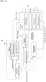
- a system for gas analysis, or a gas analyzer includes a sensor unit 1, a temperature controller 16, a gas supply unit 17, a velocity measurement unit 18 and a signal processing unit 40.
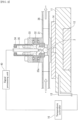
- the sensor unit 1 as illustrated in Fig. 2 , has a SAW sensor 2, which is a ball SAW sensor, embedded in a tubular sensor cell 31, wherein the tubular sensor cell 31 is fixed on a plate-shaped adapter 14 disposed on a block-shaped holder 11.
- the inner structure of the sensor cell 31 has a concave configuration for mounting a lower portion of the SAW sensor 2 in a tubular topology of the sensor cell 31.
- An electrode-holder base 32 is fixed on the sensor cell 31, such that the bottom of the electrode-holder base 32 is inserted in an inner wall of a window, which is vertically cut at the top wall of the sensor cell 31.
- a top of the electrode-holder base 32 is capped by a sensor-cell cap 33.
- the SAW sensor 2 is connected to a rod-shaped external electrode 35 through a contact pin 35a along a vertical direction via the canal at the bottom of the electrode-holder base 32.
- the external electrode 35 is held in a hollow space of a vertically aligned cylindrical electrode holder 34, the bottom of which is inserted in an inner portion of the sensor-cell cap 33.
- a sensing gas containing in a background gas for example, a humid gas, is introduced into the sensor cell 31 through a horizontally aligned tubing 36 with a gas flow rate v, so that the humid gas can touch the surface of the SAW sensor 2.
- the gas flow rate v is typically 0.1 L/min to 1 L/min.
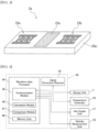
- the SAW sensor 2 may have a sensor electrode 22 and a sensitive film 23 arranged in predetermined areas on the surface of a homogeneous piezoelectric ball 20.
- the piezoelectric ball 20 provides a homogeneous material sphere, on which a circular orbital band for propagating a SAW can be defined.
- the sensor electrode 22 generates a collimated beam 21 of the SAW, which includes a fundamental wave of a first frequency and a harmonic wave of a second frequency, propagates repeatedly through the circular orbital path defined on the piezoelectric ball 20 while passing through the sensitive film 23 deposited on the orbital path.
- the sensitive film 23 can be formed on almost the entire surface of the orbital band, which defines the orbital path on the three-dimensional base body. Because the sensitive film 21 is configured to react with specific gas molecules, the sensitive film 21 adsorbs water vapor in the sensing gas-to-be-measured.
- a crystal sphere such as quartz, langasite (La 3 Ga 5 SiO 14 ), lithium niobate (LiNbO 3 ), lithium tantalate (LiTaO 3 ), piezoelectric ceramics (PZT), bismuth germanium oxide (Bi 12 GeO 20 ) and the like, may be used.
- a silica (SiO x ) film and the like may be used.
- the sensor electrode 22 may be deposited in an opening of the sensitive film 23, the opening exposes a part of the surface of the piezoelectric ball 20, in a configuration such that the opening is formed on a part of the equator of the homogeneous piezoelectric ball 20.
- an interdigital electrode (IDT) using a chromium (Cr) film and the like may be used as an electroacoustic transducer.
- IDT interdigital electrode
- Cr chromium
- a SAW orbiting route is limited to a specific orbital band having a constant width, depending on type of crystal material. The width of the orbital band may be increased or decreased depending on anisotropy of the crystal.
- the collimated beam 21 is scheduled to propagate many turns passing through the sensitive film 23, which is configured to adsorb water molecules. Because the adsorbed water molecules change the propagation characteristic of the SAW, the changes due to adsorbed water molecules in the humid gas on the sensitive film 23 can be integrated every turn through the multiple roundtrips. Thus, even though the sensitive film 23 may be so thin as to adsorb the small amount of the water vapor, measurement accuracy of gas analysis may be increased.
- the second frequency f 2 is 240 MHz for the third-order harmonic wave or 400 MHz for the fifth-order harmonic wave.
- Appropriate range of the first frequency f 1 for the piezoelectric ball 20 of 3.3 millimeters diameter may be from 60 MHz to 100 MHz, and the most suitable first frequency f 1 may be 80 MHz.
- the first frequency f1 is inversely proportional to the diameter of the piezoelectric ball 20.
- the SAW sensor 2 may be fabricated as described below.
- a pattern of an IDT of about 150 nanometers thick Cr film is deposited on a surface of a quartz ball having a diameter of 3.3 millimeters.
- the IDT has a pair of bus bars, and a plurality of electrode fingers extending from the bas bars, respectively.
- the electrode fingers overlap each other with a cross width Wc, and each electrode finger has a width Wf and a periodicity P.
- the cross width Wc, the width Wf and the periodicity P are designed as 364 micrometers, 6.51 micrometers and 10.0 micrometers, respectively, for the natural collimation of 80 MHz SAW (refer to NPL 1).
- the IDT on the quartz ball having 3.3 millimeters diameter can generate 80 MHz SAW as a fundamental wave and 240 MHz SAW as a third-order harmonic wave.
- a silica film is synthesized by using a sol-gel method and coated on the surface of the quartz ball as follows: 3.47 grams of tetraethoxysilane (TEOS), 0.75 grams of isopropanol (IPA), and 1.50 grams of 0.1N hydrochloric acid (HCl) are mixed and stirred by sonication (27, 45, 100 kHz, 60 minutes).
- TEOS is polymerized by hydrolysis and resulted in SiO x .
- the mixture is diluted with IPA and 0.5 mass% SiO x solution is obtained.
- the surface of propagation route of SAW is coated with the SiO x solution using a spin coating. Condition of the spin coating is 3000 rpm for 20 seconds.
- the thickness of SiO x film is confirmed as 1029 nanometers from measurement using interference microscope.
- An RF voltage is applied to the sensor electrode 22 via an electrode pad (not illustrated) arranged around the north-pole, which is a top of the piezoelectric ball 20 in Fig. 3 , using the contact pin 35a attached on the bottom of the external electrode 35.
- Another electrode pad (not illustrated) arranged around the south-pole, which is a bottom of the piezoelectric ball 20 in Fig. 3 is in contact with the grounded sensor cell 31.
- a ball SAW sensor is used as the SAW sensor 2.
- a planar SAW sensor 2a illustrated in Fig. 4 may be used.
- the planar SAW sensor 2a have an input electrode 22a, a sensitive film 23a and an output electrode 22b, which are arranged in predetermined areas on the surface of a homogeneous piezoelectric substrate 20a.
- the temperature controller 16 is connected to a Peltier element 12, which is held in a lower portion of the holder 11 at a position just below the SAW sensor 2, and a thermistor 13 is inserted in the holder 11 at a side position of the holder 11. Furthermore, the temperature controller 16 is connected to the thermistor 13.
- the Peltier element 12 is used for heating and cooling the SAW sensor 2 in the sensor cell 31 through the adapter 14.
- the thermistor 13 is used for detecting a monitoring temperature T th of the holder 11.
- the temperature controller 16 controls the Peltier element 12 by using the monitoring temperature T th . As illustrated in Fig.
- the thermistor 13 cannot be directly inserted into the sensor cell 31 to prevent leakage of gases through the sensor cell 31. Note that, although the thermistor 13 is used for detecting the monitoring temperature T th in the first embodiment, but other thermometers, such as a thermocouple and the like, may be used.
- the signal processing unit 40 includes a signal generator and a signal receiver (hereinafter the set of the signal generator and the signal receiver is referred as the "signal generator/receiver") 42 and a waveform data processor 44.
- the signal generator/receiver 42 includes a signal generator 42a, and a signal receiver 42b.
- the waveform data processor 44 includes a communication module (communication logical circuit) 45, a calculation module (calculation logical circuit) 46, a comparison module (comparison logical circuit) 47, and a memory unit 48 for logical hardware resources of a computer system.
- the communication module 45 of the waveform data processor 44 sends a predetermined "set temperature” or a control temperature for the Peltier element 12 to the temperature controller 16, which are illustrated in Figs. 1 and 2 . And, the communication module 45 sends instructions for flowing a gas into the sensor cell 31 to the sensor unit 1 and the gas supply unit 17 illustrated in Figs. 5 and 6 . Moreover, the communication module 45 sends instructions for measuring a sound velocity in the gas supplied from the gas supply unit 17 to the velocity measurement unit 18. In addition, when the velocity measurement of the gas is not necessary, the gas may be directly supplied to the sensor unit 1 from the gas supply unit 17.
- the communication module 45 sends instructions to the signal generator/receiver 42 so that the signal generator 42a illustrated in Fig. 1 transmits an exciting burst signal to the sensor electrode 22 of the SAW sensor 2 and the sensor electrode 22 can excite the collimated beam 21 of a SAW propagating around the piezoelectric ball 20 illustrated in Fig. 3 .
- the communication module 45 sends instructions to the signal generator/receiver 42 so that the signal receiver 42b illustrated in Fig. 1 can receive returned burst signals of the collimated beam 21 through the sensor electrode 22 after the collimated beam 21 has propagated a predetermined number of turns around the piezoelectric ball 20 illustrated in Fig. 3 .
- the signal generator/receiver 42 transmits waveform data of the returned burst signals to the waveform data processor 44.
- the calculation module 46 of the waveform data processor 44 calculates a gas parameter by using first and second attenuations in amplitudes of the SAWs of the first and second frequencies, respectively, using the waveform data of the returned burst signals.
- the comparison module 47 of the waveform data processor 44 compares the calculated gas parameter with data of gas parameters for various gases in order to determine gas species.
- the memory unit 48 of the waveform data processor 44 stores a program for driving the waveform data processor 44 to implement processing of the waveform data for calculating the gas parameter. Also, the memory unit 48 stores the data of gas parameters for various gases, and data obtained during the calculation and analysis of the gas during the operation of the waveform data processor 44.
- the waveform data processor 44 may be a part of central processing unit (CPU) of a general purpose computer system, such as a personal computer (PC) and the like.
- the waveform data processor 44 may include an arithmetic logic unit (ALU) that performs arithmetic and logic operations, a plurality of registers that supply operands to the ALU and store the results of ALU operations, and a control unit that orchestrates the fetching (from memory) and execution of instructions by directing the coordinated operations of the ALU.
- ALU arithmetic logic unit
- the communication module 45, the calculation module 46, and the comparison module 47 implementing the ALU may be discrete hardware resources such as logical circuit blocks or the electronic circuitry contained on a single integrated circuit (IC) chip, or alternatively, may be provided by virtually equivalent logical functions achieved by software, using the CPU of the general purpose computer system.
- IC integrated circuit
- the program for the waveform data processor 44 for the gas analysis is not limited to being stored in the memory unit 48 installed in the waveform data processor 44.
- the program may be stored in an external memory.
- the program may be stored in a computer readable medium.
- the waveform data processor 44 implements coordinated operations for the gas analysis, in accordance with a sequence of instructions recited in the program.
- the "computer readable medium” refers to a recording medium or a storage medium, such as an external memory unit of a computer, a semiconductor memory, a magnetic disk, an optical disk, a magneto optical disk, and a magnetic tape, on which the program can be recorded.
- f is a frequency
- ⁇ s is a density of the piezoelectric ball 20
- V s is a SAW velocity of the piezoelectric ball 20
- ⁇ is a density of the gas
- K G is a compressibility of the gas.
- ⁇ L fP ⁇ S V S 2 ⁇ M RT , where M is a molecular weight of the gas, P is a pressure of the gas, R is a gas constant, T is a temperature and ⁇ is the heat capacity ratio which is ratio of the specific heat at constant pressure to the specific heat at constant volume of the gas.
- a leakage factor ⁇ L is defined as ⁇ ⁇ L ⁇ f 2 / f 1 x ⁇ 1 ⁇ ⁇ 2 / l , where the superscript "u" is an index to describe the frequency dependence of the attenuation by the sensing gas, which is 1.8 or more and 2.3 or less, and l is the SAW propagation length.
- [ ⁇ M] 1/2 in Eq. (7) is an important parameter describing property of the background gas, and thus it is defined as a gas parameter, here.
- gas parameters G or "reference gas parameters”, for typical light gasses, each of which is calculated by molecular weight M and heat capacity ratio ⁇ of each gas, are listed in a table of Fig. 8 . It is noted that the order of magnitude of the gas parameter is not identical to that of molecular weight, nor that of heat capacity ratio.
- F 2 3F 1
- F 1 1
- Coefficient A and term d caused by device loss can be determined by calibration.
- the leakage factor ⁇ L is first measured at T 1 and P 1 for a gas having a gas parameter G 1 and secondly at T 2 and P 2 for a gas having a gas parameter G 2 .
- the gas supply unit 17 used for the test measurement includes a plurality of gas sources 52a, 52b, 52c, 52d, a gas controller 50 and a moisture generator 54.
- Each of the gas sources 52a, 52b, 52c, 52d includes a gas container of a background gas and a flow controller for controlling a flow rate of the background gas, and supplies the background gas to the sensor unit 1 through the gas-switching valve 50 and the moisture generator 54.
- the velocity measurement unit 18 is omitted for convenience of explanation.
- the gas source 52a supplies a nitrogen (N 2 ) gas
- the gas source 52b supplies an argon (Ar) gas
- the gas source 52c supplies a methane (CH 4 ) gas
- the gas source 52d supplies air.
- the gas-switching valve 50 switches to select the background gas from the gas sources 52a, 52b, 52c, 52d by instructions of the communication module 45 of the waveform data processor 44.
- the moisture generator 54 generates the trace moisture as the sensing gas in the background gas at a predetermined concentration by instructions of the communication module 45 illustrated in Fig. 5 .
- the humid gas at a predetermined frost point, or a predetermined water concentration can be supplied to the sensor unit 1.
- the background gases X3, X4, X5, X6 have been used as target gases.
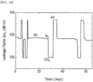
- the background gas has been changed in order of X6, X3, X5 and X4, as illustrated in Fig. 13 , and the leakage factor ⁇ L has been measured as illustrated in Fig. 14 . Since the measured gas parameters G* of the background gases X3, X4, X5, X6, listed in a table of Fig.
- the gas analyzer it is also possible to measure a concentration of the sensing gas in the background gas with high precision using the viscoelastic factor ⁇ V , even when composition of the background gas is changed.
- the leakage factor ⁇ L evaluated using Eq. (4) and the viscoelastic factor ⁇ V evaluated using Eq. (15) have been compared in a wide time range of about 65 hours using humid gases having the frost points of -60°C, -50°C and -40°C, which correspond to 10.7 ppmv, 38.8 ppmv and -127 ppmv, as illustrated in Figs.
- the leakage factor ⁇ L is independent of the moisture content, as illustrated in Fig. 18 .
- the viscoelastic factor ⁇ V is almost independent on the change in the background composition and represents only the change in moisture content.
- the viscoelastic factor ⁇ V is useful for the moisture measurement under different background gases without time-consuming recalibration procedure for each background gas.
- each of M(bar), G(bar), ⁇ (bar) , C p (bar) and C v (bar), etc. represents a symbol labeled with an horizontal over line, or an over bar on the top of the characters of M, ⁇ , C p and C v , etc.
- x is the concentration by mole percentage, or mol%, of gas XA
- M A , C PA and C VA are molecular weight, specific heat at a constant pressure and specific heat at constant volume of the gas XA
- M B , C PB , C VB are molecular weight, specific heat at a constant pressure and specific heat at constant volume of the gas XB, respectively.
- the measured leakage factor ⁇ L in the measurement sequence is plotted against time in Fig. 21 .
- the average gas parameter G(bar) has been calculated over the last ten minutes of each step, and plotted by open circles against the He concentration in Fig. 22 .
- the measured values of the average gas parameter G(bar) agree well with a calculated curve, illustrated by solid curve in Fig. 22 , using Eq. (19) with parameters listed in Fig. 20 .
- the concentration of He can be measured by the average gas parameter G(bar) with using a calibration curve.
- the calibration curve may be calculated by replacing C PB with ⁇ C PB and C VB with ⁇ C VB in Eq. (19) where the ⁇ is an adjustable parameter.
- the adjustable parameter ⁇ has no physical meaning, the adjustable parameter ⁇ helps to improve the agreement between the experimental data and the calibration curve when the adjustable parameter ⁇ is set to 3.0, as illustrated by dotted curve in Fig. 22 , which is slightly deformed and shifted from the solid curve.
- He concentration has been measured as illustrated in Fig. 23 , where set concentration has been increased in order from 0 mol% to 10 mol% by 2 mol% steps, decreased from 10 mol% to 0 mol% by 2 mol% steps, increased from 0 mol% to 100 mol% by 10 mol% steps and decreased from 100 mol% to 0 mol% by 10 mol% steps.
- the measured concentration has been compared with the set concentration and it has been confirmed that good agreement between the set concentration and measured concentration has been obtained as illustrated in Fig. 24 .
- the standard deviation of the measured concentration from the set concentration has been about 0.96% in the measurement of He 0 mol% to 100 mol%.
- the gas analyzer for checking whether an interior of a glove box has been replaced with a purge-gas.
- the glove box used for Li-ion batteries or for 3D printers of metal objects it is required to replace air and moisture in the glove box with the purge-gas.
- an inert gas such as argon, helium, N 2 and the like, or a mixture of inert gases may be preferably used to avoid unwanted chemical reactions with oxygen (O 2 ) in the air and the moisture.
- the purge-gas and the air may be implemented by the mix gas and concentration of the purge-gas may increase with time.
- concentration of the purge-gas as a component gas, which is mixed with the air in the glove box, using the gas parameter G(bar) of Eq. (19).
- concentration of the moisture in the glove box may be also measured as the sensing gas using the viscoelastic factor ⁇ V of Eq. (15).
- the average molecular weight M(bar) and the average specific heat ratio ⁇ (bar) are useful for calculation of many physical/chemical property of the mix gas.
- the gas analyzer can measure a sound velocity of the gas by the velocity measurement unit 18 using an ultrasonic wave having a frequency in a range of 10kHz to 100kHz.
- V bar 1 / ⁇ bar K G bar 1 / 2
- it is useful to express the average leaky attenuation coefficient ⁇ L (bar) as ⁇ L bar f ⁇ bar / K G bar 1 / 2 / ⁇ S V S 2 similarly to Eq. (1). Then, from Eqs.
- the average molecular weight and the average specific heat ratio can not be separated by merely measuring the average gas parameter. However, by adding measurement of the average sound velocity of the mix gas, it is possible to independently measure the average molecular weight and the average specific heat ratio. Thus, there is an advantage that other thermodynamic quantities can be calculated by independently measuring the average molecular weight and the average specific heat ratio.
Landscapes
- Physics & Mathematics (AREA)
- Chemical & Material Sciences (AREA)
- Health & Medical Sciences (AREA)
- Life Sciences & Earth Sciences (AREA)
- General Physics & Mathematics (AREA)
- Biochemistry (AREA)
- Analytical Chemistry (AREA)
- Pathology (AREA)
- General Health & Medical Sciences (AREA)
- Immunology (AREA)
- Acoustics & Sound (AREA)
- Engineering & Computer Science (AREA)
- Signal Processing (AREA)
- Food Science & Technology (AREA)
- Medicinal Chemistry (AREA)
- Combustion & Propulsion (AREA)
- Algebra (AREA)
- Mathematical Analysis (AREA)
- Mathematical Optimization (AREA)
- Mathematical Physics (AREA)
- Pure & Applied Mathematics (AREA)
- Investigating Or Analyzing Materials By The Use Of Ultrasonic Waves (AREA)
Description
- The present invention relates to a system, a method and a computer program product for gas analysis using a surface acoustic wave (SAW) sensor, and especially, using a ball SAW sensor.
- In oil and gas industry, trace moisture sensors in natural gas are used, but variation of composition in background gases degrades the precision of the sensors. The composition variation takes place when the gas production condition is changed. Also, the composition of background gases is an important parameter for evaluating the heat value. Thus, the composition of background gases is usually measured by gas chromatography (GC), but GC is large and expensive apparatus.
- As recited in non patent literature (NPL) 1, a ball SAW sensor has been developed and applied to a trace moisture sensor. In the ball SAW sensor, the SAW excited on a spherical surface with a specific condition may be naturally collimated, and multiple roundtrips along the equator of the ball can be realized. Thus, the ball sensor based on the multiple-roundtrips effect of the SAW may provide high performance, such as high sensitivity and wide sensing range. Further, in
NPL 2, SAW attenuation due to propagation at the boundary between a solid and a monatomic gas is described. Further, inNPL 3, frequency dependence of SAW attenuation by a gas is described. Further, documentsUS 2010/018288 A1 ,JP 2008 245003 A US 2017/307567 A1 and the paper of TAKEDA et al. ("Deep Sub-micro mol mol Water-Vapor Measurement by Dual-Ball SAW Sensors for Temperature Compensation", INTERNATIONAL JOURNAL OF THERMOPHYSICS SPRINGER NEW YORK USA, SPRINGER NEW YORK LLC, US, vol. 36, no. 12, 23 August 2015, pages 3440-3452), disclose gas analysis by means of a ball SAW sensor driven at two different frequencies, wherein a sensitive layer is deposited on the ball so that a collimated SAW beam passes through it. - In a new technology for hydrogen transport, hydrogen is injected into natural gas and carried in natural gas pipeline system, as reported in
NPL 4. In the technology, rapid hydrogen concentration measurement is needed in a concentration range up to 10 %. Though sound velocity measurement, thermal conductivity measurement, and infra-red spectroscopy are used for analysis of natural gases, fast and precise hydrogen gas sensor is not available. -
- [NPL 1]: K. Yamanaka, et al.: Institute of Electrical and Electronics Engineers (IEEE) Transactions on Ultrasonics, Ferroelectrics, and Frequency Control, vol.53 (2006) pp.793
- [NPL 2]: A. J. Slobodnik, Jr.: J. Appl. Phys., 43, 2565 (1972)
- [NPL 3]: S. J. Martin, et al.: Anal. Chem. 66, 2201 (1994).
- [NPL 4]: A. Witkowski, et al.: J. Press. Vessels Pip. 166, 24 (2018).
- In view of the above problems, an object of the present invention is to provide a system, a method and a computer program product for gas analysis, which facilitate a high precision measurement of gas species and concentration in a short time.
- A first aspect of the present invention inheres in a system for gas analysis, as defined in claim 1. Preferred features are defined in the dependent claims.
- A second aspect of the present invention inheres in a method for gas analysis, as defined in
claim 9. Preferred features are defined in the dependent claims. - A third aspect of the present invention inheres in a computer program product, as defined in
claim 17. - According to the present invention, it is possible to provide the system, the method and the computer program product for gas analysis, which facilitate a high precision measurement of gas species and concentration in a short time.
-
- [
Fig. 1 ]
Fig. 1 is a block diagram illustrating an example of a gas analyzer using a SAW sensor according to an embodiment of the present invention; - [
Fig. 2 ]
Fig. 2 is a schematic cross sectional view illustrating an example of a system for the gas analysis using the SAW sensor according to the embodiment of the present invention; - [
Fig. 3 ]
Fig. 3 is a schematic view illustrating an example of the SAW sensor used in the gas analyzer according to the embodiment of the present invention; - [
Fig. 4 ]
Fig. 4 is a schematic view illustrating an example of a SAW sensor, which is not in accordance with the invention as claimed; - [
Fig. 5 ]
Fig. 5 is a block diagram illustrating an example of the signal processing unit in the system for the gas analysis according to the embodiment of the present invention; - [
Fig. 6 ]
Fig. 6 is a block diagram illustrating an example of the gas supply unit in the system for the gas analysis according to the embodiment of the present invention; - [
Fig. 7 ]
Fig. 7 is a flow chart illustrating an example of a method for the gas analysis according to the embodiment of the present invention; - [
Fig. 8 ]
Fig. 8 is a table illustrating examples of gas parameters for typical light gasses according to the embodiment of the present invention; - [
Fig. 9 ]
Fig. 9 is a diagram illustrating examples of attenuations of the SAWs at frequencies f1 and f2 by changing background gases according to a first example of the embodiment of the present invention; - [
Fig. 10 ]
Fig. 10 is a diagram illustrating examples of leakage factors of the SAWs by changing the background gases according to the first example of the embodiment of the present invention; - [
Fig. 11 ]
Fig. 11 is a table illustrating examples of the measured gas parameters for the background gases according to the first example of the embodiment of the present invention; - [
Fig. 12 ]
Fig. 12 is a diagram illustrating an example of a relationship between the leakage factor and a gas parameter according to the first example of the embodiment of the present invention; - [
Fig. 13 ]
Fig. 13 is a diagram illustrating other examples of attenuations of the SAWs at frequencies f1 and f2 by changing background gases according to the first example of the embodiment of the present invention; - [
Fig. 14 ]
Fig. 14 is a diagram illustrating other examples of leakage factors of the SAWs by changing the background gases according to the first example of the embodiment of the present invention; - [
Fig. 15 ]
Fig. 15 is a table illustrating other examples of measured gas parameters for the background gases according to the first example of the embodiment of the present invention; - [
Fig. 16 ]
Fig. 16 is a diagram illustrating another example of the relationship between the leakage factor and the gas parameter according to the first example of the embodiment of the present invention; - [
Fig. 17 ]
Fig. 17 is a diagram illustrating the summarized gas parameters measured by the gas analyzer according to the embodiment of the present invention; - [
Fig. 18 ]
Fig. 18 is a diagram illustrating examples of leakage factors of the SAW by changing the background gases according to a first modification of the embodiment of the present invention; - [
Fig. 19 ]
Fig. 19 is a diagram illustrating examples of viscoelastic factors of the SAW by changing the background gases according to the first modification of the embodiment of the present invention; - [
Fig. 20 ]
Fig. 20 is a table illustrating properties of He and N2 according to a second modification of the embodiment of the present invention; - [
Fig. 21 ]
Fig. 21 is a diagram illustrating an example of a leakage factor by changing the He concentration in mix gas of He and N2 according to the second modification of the embodiment of the present invention; - [
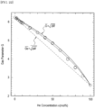
Fig. 22 ]
Fig. 22 is a diagram illustrating an example of a gas parameter against He concentration according to the second modification of the embodiment of the present invention; - [
Fig. 23 ]
Fig. 23 is a diagram illustrating an example of measured He concentration by changing the set He concentration in mix gas of He and N2 according to the second modification of the embodiment of the present invention; and - [
Fig. 24 ]
Fig. 24 is a diagram illustrating an example of comparison between the measured concentration and the set concentration of He according to the second modification of the embodiment of the present invention. - Embodiments of the present invention will be described below with reference to the drawings. In the descriptions of the following drawings, the same or similar reference numerals are assigned to the same or similar portions. However, the drawings are diagrammatic, and attention should be paid to a fact that the relations between thicknesses and plan view dimensions, the configuration of the apparatus and the like differ from the actual data. Thus, the specific thicknesses and dimensions should be judged by considering the following descriptions. Also, even between the mutual drawings, the portions in which the relations and rates between the mutual dimensions are different are naturally included. Also, the first and second embodiments as described below exemplify the apparatuses and methods for embodying the technical ideas of the present invention, and in the technical ideas of the present invention, the materials, shapes, structures, arrangements and the like of configuration parts are not limited to the followings.
- In the following description, α, β, γ, Δ and ρ represent Greek alphabet characters, respectively. And, the "horizontal" direction or the "vertical" direction is simply assigned for convenience of explanation and does not limit the technical spirit of the present invention. Therefore, for example, when the plane of paper is rotated 90 degrees, the "horizontal" direction is changed to the "vertical" direction and the "vertical" direction is changed to the "horizontal" direction. When the plane of paper is rotated 180 degrees, the "left" side is changed to the "right" side and the "right" side is changed to the "left" side. Therefore, various changes can be added to the technical ideas of the present invention, within the technical scope prescribed by claims.
- As illustrated in
Fig. 1 , a system for gas analysis, or a gas analyzer, pertaining to an embodiment of the present invention includes a sensor unit 1, atemperature controller 16, agas supply unit 17, avelocity measurement unit 18 and asignal processing unit 40. The sensor unit 1, as illustrated inFig. 2 , has aSAW sensor 2, which is a ball SAW sensor, embedded in atubular sensor cell 31, wherein thetubular sensor cell 31 is fixed on a plate-shapedadapter 14 disposed on a block-shapedholder 11. As theSAW sensor 2 has spherical shape, the inner structure of thesensor cell 31 has a concave configuration for mounting a lower portion of theSAW sensor 2 in a tubular topology of thesensor cell 31. An electrode-holder base 32 is fixed on thesensor cell 31, such that the bottom of the electrode-holder base 32 is inserted in an inner wall of a window, which is vertically cut at the top wall of thesensor cell 31. An opening of a canal, which penetrates vertically through the bottom of the electrode-holder base 32, partially covers an upper portion of theSAW sensor 2. Furthermore, a top of the electrode-holder base 32 is capped by a sensor-cell cap 33. - The
SAW sensor 2 is connected to a rod-shaped external electrode 35 through acontact pin 35a along a vertical direction via the canal at the bottom of the electrode-holder base 32. The external electrode 35 is held in a hollow space of a vertically alignedcylindrical electrode holder 34, the bottom of which is inserted in an inner portion of the sensor-cell cap 33. A sensing gas containing in a background gas, for example, a humid gas, is introduced into thesensor cell 31 through a horizontally alignedtubing 36 with a gas flow rate v, so that the humid gas can touch the surface of theSAW sensor 2. The gas flow rate v is typically 0.1 L/min to 1 L/min. - As illustrated in
Fig. 3 , theSAW sensor 2 may have asensor electrode 22 and asensitive film 23 arranged in predetermined areas on the surface of a homogeneouspiezoelectric ball 20. As a three-dimensional base body, thepiezoelectric ball 20 provides a homogeneous material sphere, on which a circular orbital band for propagating a SAW can be defined. Thesensor electrode 22 generates a collimatedbeam 21 of the SAW, which includes a fundamental wave of a first frequency and a harmonic wave of a second frequency, propagates repeatedly through the circular orbital path defined on thepiezoelectric ball 20 while passing through thesensitive film 23 deposited on the orbital path. Thesensitive film 23 can be formed on almost the entire surface of the orbital band, which defines the orbital path on the three-dimensional base body. Because thesensitive film 21 is configured to react with specific gas molecules, thesensitive film 21 adsorbs water vapor in the sensing gas-to-be-measured. - For the
piezoelectric ball 20, a crystal sphere, such as quartz, langasite (La3Ga5SiO14), lithium niobate (LiNbO3), lithium tantalate (LiTaO3), piezoelectric ceramics (PZT), bismuth germanium oxide (Bi12GeO20) and the like, may be used. For thesensitive film 23, a silica (SiOx) film and the like may be used. Thesensor electrode 22 may be deposited in an opening of thesensitive film 23, the opening exposes a part of the surface of thepiezoelectric ball 20, in a configuration such that the opening is formed on a part of the equator of the homogeneouspiezoelectric ball 20. For thesensor electrode 22, an interdigital electrode (IDT) using a chromium (Cr) film and the like may be used as an electroacoustic transducer. In the case of a sphere of single crystal such as the homogeneouspiezoelectric ball 20, a SAW orbiting route is limited to a specific orbital band having a constant width, depending on type of crystal material. The width of the orbital band may be increased or decreased depending on anisotropy of the crystal. - There are no diffraction losses during roundtrips around the
piezoelectric ball 20, and only propagation loss due to material attenuation. The collimatedbeam 21 is scheduled to propagate many turns passing through thesensitive film 23, which is configured to adsorb water molecules. Because the adsorbed water molecules change the propagation characteristic of the SAW, the changes due to adsorbed water molecules in the humid gas on thesensitive film 23 can be integrated every turn through the multiple roundtrips. Thus, even though thesensitive film 23 may be so thin as to adsorb the small amount of the water vapor, measurement accuracy of gas analysis may be increased. - The suitable relationship between the first frequency f1 of the fundamental wave and the second frequency f2 of the harmonic wave shall be represented by f2 = nf1, where n = 3 or 5. That is, in the system for gas analysis pertaining to the embodiment of the present invention, the harmonic wave is the third-order harmonic wave or the fifth-order harmonic wave. Thus, when the first frequency f1 is 80 MHz, the second frequency f2 is 240 MHz for the third-order harmonic wave or 400 MHz for the fifth-order harmonic wave. Appropriate range of the first frequency f1 for the
piezoelectric ball 20 of 3.3 millimeters diameter may be from 60 MHz to 100 MHz, and the most suitable first frequency f1 may be 80 MHz. The first frequency f1 is inversely proportional to the diameter of thepiezoelectric ball 20. - For example, the
SAW sensor 2 may be fabricated as described below. A pattern of an IDT of about 150 nanometers thick Cr film is deposited on a surface of a quartz ball having a diameter of 3.3 millimeters. The IDT has a pair of bus bars, and a plurality of electrode fingers extending from the bas bars, respectively. The electrode fingers overlap each other with a cross width Wc, and each electrode finger has a width Wf and a periodicity P. The cross width Wc, the width Wf and the periodicity P are designed as 364 micrometers, 6.51 micrometers and 10.0 micrometers, respectively, for the natural collimation of 80 MHz SAW (refer to NPL 1). - The IDT on the quartz ball having 3.3 millimeters diameter can generate 80 MHz SAW as a fundamental wave and 240 MHz SAW as a third-order harmonic wave. Then a silica film is synthesized by using a sol-gel method and coated on the surface of the quartz ball as follows: 3.47 grams of tetraethoxysilane (TEOS), 0.75 grams of isopropanol (IPA), and 1.50 grams of 0.1N hydrochloric acid (HCl) are mixed and stirred by sonication (27, 45, 100 kHz, 60 minutes). TEOS is polymerized by hydrolysis and resulted in SiOx. After sonication, the mixture is diluted with IPA and 0.5 mass% SiOx solution is obtained. The surface of propagation route of SAW is coated with the SiOx solution using a spin coating. Condition of the spin coating is 3000 rpm for 20 seconds. The thickness of SiOx film is confirmed as 1029 nanometers from measurement using interference microscope.
- An RF voltage is applied to the
sensor electrode 22 via an electrode pad (not illustrated) arranged around the north-pole, which is a top of thepiezoelectric ball 20 inFig. 3 , using thecontact pin 35a attached on the bottom of the external electrode 35. Another electrode pad (not illustrated) arranged around the south-pole, which is a bottom of thepiezoelectric ball 20 inFig. 3 , is in contact with the groundedsensor cell 31. - In the above description, a ball SAW sensor is used as the
SAW sensor 2. In an alternative arrangement, not claimed, aplanar SAW sensor 2a illustrated inFig. 4 may be used. Theplanar SAW sensor 2a have aninput electrode 22a, asensitive film 23a and anoutput electrode 22b, which are arranged in predetermined areas on the surface of a homogeneouspiezoelectric substrate 20a. - As illustrated in
Fig. 2 , thetemperature controller 16 is connected to aPeltier element 12, which is held in a lower portion of theholder 11 at a position just below theSAW sensor 2, and athermistor 13 is inserted in theholder 11 at a side position of theholder 11. Furthermore, thetemperature controller 16 is connected to thethermistor 13. ThePeltier element 12 is used for heating and cooling theSAW sensor 2 in thesensor cell 31 through theadapter 14. Thethermistor 13 is used for detecting a monitoring temperature Tth of theholder 11. Thetemperature controller 16 controls thePeltier element 12 by using the monitoring temperature Tth. As illustrated inFig. 2 , thethermistor 13 cannot be directly inserted into thesensor cell 31 to prevent leakage of gases through thesensor cell 31. Note that, although thethermistor 13 is used for detecting the monitoring temperature Tth in the first embodiment, but other thermometers, such as a thermocouple and the like, may be used. - The
signal processing unit 40, as illustrated inFig. 1 , includes a signal generator and a signal receiver (hereinafter the set of the signal generator and the signal receiver is referred as the "signal generator/receiver") 42 and awaveform data processor 44. The signal generator/receiver 42 includes asignal generator 42a, and asignal receiver 42b. As illustrated inFig. 5 , thewaveform data processor 44 includes a communication module (communication logical circuit) 45, a calculation module (calculation logical circuit) 46, a comparison module (comparison logical circuit) 47, and amemory unit 48 for logical hardware resources of a computer system. Thecommunication module 45 of thewaveform data processor 44 sends a predetermined "set temperature" or a control temperature for thePeltier element 12 to thetemperature controller 16, which are illustrated inFigs. 1 and2 . And, thecommunication module 45 sends instructions for flowing a gas into thesensor cell 31 to the sensor unit 1 and thegas supply unit 17 illustrated inFigs. 5 and6 . Moreover, thecommunication module 45 sends instructions for measuring a sound velocity in the gas supplied from thegas supply unit 17 to thevelocity measurement unit 18. In addition, when the velocity measurement of the gas is not necessary, the gas may be directly supplied to the sensor unit 1 from thegas supply unit 17. - Moreover, the
communication module 45 sends instructions to the signal generator/receiver 42 so that thesignal generator 42a illustrated inFig. 1 transmits an exciting burst signal to thesensor electrode 22 of theSAW sensor 2 and thesensor electrode 22 can excite the collimatedbeam 21 of a SAW propagating around thepiezoelectric ball 20 illustrated inFig. 3 . And furthermore, thecommunication module 45 sends instructions to the signal generator/receiver 42 so that thesignal receiver 42b illustrated inFig. 1 can receive returned burst signals of the collimatedbeam 21 through thesensor electrode 22 after the collimatedbeam 21 has propagated a predetermined number of turns around thepiezoelectric ball 20 illustrated inFig. 3 . As illustrated inFig. 5 , the signal generator/receiver 42 transmits waveform data of the returned burst signals to thewaveform data processor 44. - The
calculation module 46 of thewaveform data processor 44 calculates a gas parameter by using first and second attenuations in amplitudes of the SAWs of the first and second frequencies, respectively, using the waveform data of the returned burst signals. Thecomparison module 47 of thewaveform data processor 44 compares the calculated gas parameter with data of gas parameters for various gases in order to determine gas species. Thememory unit 48 of thewaveform data processor 44 stores a program for driving thewaveform data processor 44 to implement processing of the waveform data for calculating the gas parameter. Also, thememory unit 48 stores the data of gas parameters for various gases, and data obtained during the calculation and analysis of the gas during the operation of thewaveform data processor 44. - The
waveform data processor 44 may be a part of central processing unit (CPU) of a general purpose computer system, such as a personal computer (PC) and the like. Thewaveform data processor 44 may include an arithmetic logic unit (ALU) that performs arithmetic and logic operations, a plurality of registers that supply operands to the ALU and store the results of ALU operations, and a control unit that orchestrates the fetching (from memory) and execution of instructions by directing the coordinated operations of the ALU. Thecommunication module 45, thecalculation module 46, and thecomparison module 47 implementing the ALU may be discrete hardware resources such as logical circuit blocks or the electronic circuitry contained on a single integrated circuit (IC) chip, or alternatively, may be provided by virtually equivalent logical functions achieved by software, using the CPU of the general purpose computer system. - In addition, the program for the
waveform data processor 44 for the gas analysis is not limited to being stored in thememory unit 48 installed in thewaveform data processor 44. For example, the program may be stored in an external memory. Moreover, the program may be stored in a computer readable medium. By reading the computer readable medium in thememory unit 48 of the computer system, which includes thewaveform data processor 44, thewaveform data processor 44 implements coordinated operations for the gas analysis, in accordance with a sequence of instructions recited in the program. Here, the "computer readable medium" refers to a recording medium or a storage medium, such as an external memory unit of a computer, a semiconductor memory, a magnetic disk, an optical disk, a magneto optical disk, and a magnetic tape, on which the program can be recorded. - In
NPL 2, leaky attenuation coefficient αL of SAW is given by
piezoelectric ball 20, Vs is a SAW velocity of thepiezoelectric ball 20, ρ is a density of the gas and KG is a compressibility of the gas. Substituting known relations

- In a SAW sensor shown in
Fig. 1 , burst of two frequencies f1 and f2 is transmitted and attenuations α1 and α2 at each frequency is measured. Then a leakage factor ΔαL is defined as
- A model is constructed for the calculation purpose with


sensor electrode 22, etc., the superscript "y" is a frequency dependence index of the device loss. The index z is normally equal to 1.0 according to NPL2, as in Eq. (1) and Eq. (3), and αL*= αL is assumed as described later. However, the index z may be 0.8 or more and 1.3 or less. It is noted that the concept and process of modifications to Eq. (8) and following equations of Eq. (8) in the case of using z other than z = 1 is obvious to a person having skills in the technical field. - It is noted that [γM]1/2 in Eq. (7) is an important parameter describing property of the background gas, and thus it is defined as a gas parameter, here. Examples of gas parameters G, or "reference gas parameters", for typical light gasses, each of which is calculated by molecular weight M and heat capacity ratio γ of each gas, are listed in a table of
Fig. 8 . It is noted that the order of magnitude of the gas parameter is not identical to that of molecular weight, nor that of heat capacity ratio. - Subtracting Eq. (6) from Eq. (5) multiplied by (F2/F1)u, the leakage factor ΔαL is related to the losses by


- Coefficient A and term d caused by device loss can be determined by calibration. To determine A and d, the leakage factor ΔαL is first measured at T1 and P1 for a gas having a gas parameter G1 and secondly at T2 and P2 for a gas having a gas parameter G2. Thus, G1=A(T1 1/2/P1)(ΔαL,1-d) and G2= A(T2 1/2/ P2)(ΔαL,2 - d) giving

In the second measurement, all parameters (T2, P2, G2) do not have to be changed from (T1, P1, G1). Different gas species can be measured at the same temperature and the same pressure, that is, calibration-condition (T2=T1, P2=P1, G2≠G1) or only the pressure is changed, that is, calibration-condition (T2=T1, P2 #P1, G2=G1). In an environment with constant temperature T or pressure P, calibration can be made by

- Since the leaky attenuation is proportional to the first frequency F1 and the second frequency F2 when z is equal to 1 in Eqs. (5) and (6), it will be cancelled in a viscoelastic factor ΔαV defined and given by


- Test measurements for gas analysis of background gases have been executed using a humid gas in which trace moisture as a sensing gas has been mixed in various background gases. The
gas supply unit 17 used for the test measurement, as illustrated inFig. 6 , includes a plurality ofgas sources gas controller 50 and amoisture generator 54. Each of thegas sources valve 50 and themoisture generator 54. Note that, inFig. 6 , thevelocity measurement unit 18 is omitted for convenience of explanation. In the test measurement, for example, thegas source 52a supplies a nitrogen (N2) gas, thegas source 52b supplies an argon (Ar) gas, thegas source 52c supplies a methane (CH4) gas, and thegas source 52d supplies air. The gas-switchingvalve 50 switches to select the background gas from thegas sources communication module 45 of thewaveform data processor 44. Themoisture generator 54 generates the trace moisture as the sensing gas in the background gas at a predetermined concentration by instructions of thecommunication module 45 illustrated inFig. 5 . Thus, the humid gas at a predetermined frost point, or a predetermined water concentration can be supplied to the sensor unit 1. - In the test measurement, the fundamental wave and the third-order harmonic wave of the SAW, that is, f2 = 3f1, has been used. Each procedure of the test measurements will be described with reference to the flowchart illustrated in
Fig. 7 . In addition, in the test measurement, the background gas has been assigned as a "target gas" in the humid gas. - In step S100, the
gas supply unit 17 supplies the humid gas with the background gas, which is selected from thegas sources 52a to 52d, into the sensor unit 1. In step S101, thesignal generator 42a of the signal generator/receiver 42 transmits the burst signal to theSAW sensor 2, so as to excite the collimatedbeam 21 of the SAW as illustrated inFigs. 1-3 . In step S102, after the collimatedbeam 21 has propagated a predetermined number of turns around theball sensor 2, thesignal receiver 42b of the signal generator/receiver 42 receives the returned burst signals of the collimatedbeam 21 through theball sensor 2. Waveform data of the returned burst signals is transmitted to thewaveform data processor 44. - In step S103, the
waveform data processor 44 measures a first attenuation α1 of a first burst signal having the first frequency f1 and a second attenuation α2 of a second burst signal having the second frequency f2. In step S104, thewaveform data processor 44 calculates the target gas parameter G of the target gas using the leaky attenuation coefficient αL and the leakage factor ΔαL, which is derived by the first and second attenuations α1 and α2 using Eqs. (4) and (11). Then, in Step S105, thewaveform data processor 44 estimates a gas species of the target gas by comparing the measured gas parameter with the true gas parameters, or the reference gas parameters, which are calculated by the physical-property data of gases. In addition, thewaveform data processor 44 measures the viscoelastic factor ΔαV of the target gas using Eq. (15) so as to calculate a concentration of the sensing gas. - An example of calibration for the coefficient B and the term d in Eqs. (13) and (14) will be described below. In the calibration procedure, a humid gas having frost point of -60°C or water concentration of 10.7 ppmv has been used with background gases of Air, N2, Ar and CH4 which have been supplied from the
gas source 52a to 52d of thegas supply unit 17 illustrated inFig. 6 . In the humid gas, the background gas has been changed in order of Air, N2, Ar and CH4, and the first and second attenuations α1 and α2 have been measured, as illustrated inFig. 9 . Then, the leakage factor ΔαL has been measured using the first and second attenuations α1 and α2, as plotted inFig. 10 . In the measurement, the propagation length l of the SAW has been set to be l=41.47 mm. In the case of the calibration using N2 and Ar, the relation between gas parameters G and the leakage factors ΔαL, which have been calculated using the known values of gas parameters G for N2 and Ar, has been plotted as closed circles inFig. 12 . Extrapolating a straight line connecting two closed circles extending to G=0 with M=0, the coefficient B and the term d caused by device loss in Eqs. (13) and (14) have been calibrated as B=0.1085 and d=58.53 dB/m. - Assuming that the first background gas and the fourth background gas in
Fig. 9 are unknown, let the first and the fourth background gases, which are air and CH4, be target gases X2 and X1, respectively. Then, the target gases X2 and X1 have been estimated by using the gas analyzer pertaining to the embodiment of the present invention as illustrated inFig. 1 . - Using Eq. (11) with the calibrated parameter B, measured gas parameters G*, or target gas parameters G*, of the target gases X1 and X2 have been measured, as 4.43 and 6.36 as listed in a table of
Fig. 11 . Comparing with the gas parameters G listed in the table illustrated inFig. 8 , which will be denoted by the "true gas parameters" below, it has been understood that the values of the measured gas parameters G* of the target gases X1 and X2 have been most close to the true gas parameter 4.56 of CH4 and the true gas parameter 6.35 of Air. Thus, the target gases X1 and X2 can be estimated to be CH4 and Air, respectively. The open circles, which indicates the measured gas parameters G* of the target gases X1, X2, are close to the calibration straight line illustrated inFig. 12 and the measurement error from the true gas parameters G has been evaluated as -2.89 % and 0.228 %, respectively, as listed in the table illustrated inFig. 11 . - In a humid gas having another humidity of frost point of -50°C and water concentration of 38.8 ppmv, the background gases X3, X4, X5, X6 have been used as target gases. The background gas has been changed in order of X6, X3, X5 and X4, as illustrated in
Fig. 13 , and the leakage factor ΔαL has been measured as illustrated inFig. 14 . Since the measured gas parameters G* of the background gases X3, X4, X5, X6, listed in a table ofFig. 15 , are very close to the true gas parameters G of 6.26, 8.17, 4.56 and 6.35, which correspond to N2, Ar, CH4 and Air, the target gases can be estimated to be X3=N2, X4=Ar, X5=CH4 and X6=Air, respectively. The measured gas parameters G* has been very close to an extrapolated straight line inFig. 16 , and the measurement error has been less than 2.7% as illustrated in the table illustrated inFig. 15 . - The measured gas parameters G* and the true gas parameters G are summarized in a graph illustrated in
Fig. 17 . The agreement between the measured gas parameters G* and the true gas parameters G is significant. The result of the graph ofFig. 17 , which indicates that the measurement of the background gas is not disturbed by changing the humidity as the sensing gas, provides the accuracy of the gas analyzer according to the embodiment of the present invention. - In the gas analyzer according to the embodiment of the present invention, it is also possible to measure a concentration of the sensing gas in the background gas with high precision using the viscoelastic factor ΔαV, even when composition of the background gas is changed. To verify that the viscoelastic factor ΔαV does not depend on the background composition but only on the moisture content, the leakage factor ΔαL evaluated using Eq. (4) and the viscoelastic factor ΔαV evaluated using Eq. (15) have been compared in a wide time range of about 65 hours using humid gases having the frost points of -60°C, -50°C and -40°C, which correspond to 10.7 ppmv, 38.8 ppmv and -127 ppmv, as illustrated in
Figs. 18 and19 . Then, it is confirmed that the leakage factor ΔαL is independent of the moisture content, as illustrated inFig. 18 . In contrast, as illustrated inFig. 19 , the viscoelastic factor ΔαV is almost independent on the change in the background composition and represents only the change in moisture content. Thus, the viscoelastic factor ΔαVis useful for the moisture measurement under different background gases without time-consuming recalibration procedure for each background gas. - In the following explanation of the second example, each of M(bar), G(bar), γ(bar) , Cp(bar) and Cv(bar), etc. represents a symbol labeled with an horizontal over line, or an over bar on the top of the characters of M, γ, Cp and Cv, etc.
- In a mix gas having a plurality of component gases, an average gas parameter G(bar) is given by

- where M(bar) is average molecular weight and γ(bar) is average ratio of average specific heat Cp(bar) at constant pressure to average specific heat Cv(bar) at constant volume. M(bar), Cp(bar) and Cv(bar) are given by

- where Mi, CPi, CVi, xi and N are molecular weight, specific heat at constant pressure, specific heat at constant volume, molar fraction of each component gas i and number digit of component gases, respectively.
- In the case of two background gases of XA and XB, G(bar) is derived as

- To verify Eq. (19), helium (He) as the gas XA has been mixed with N2 as gas XB, where molecular weight, specific heat at a constant pressure, specific heat at constant volume, ratio of specific heats and gas parameter of He and N2 are listed in
Fig. 20 . The measurement sequence was performed in which He concentration has been increased from 0% to 100% with 10% steps and decreased from 100% to 0% with 10% steps. The measurement time of each step has been 20 min. - The measured leakage factor αL in the measurement sequence is plotted against time in
Fig. 21 . Then, the average gas parameter G(bar) has been calculated over the last ten minutes of each step, and plotted by open circles against the He concentration inFig. 22 . The measured values of the average gas parameter G(bar) agree well with a calculated curve, illustrated by solid curve inFig. 22 , using Eq. (19) with parameters listed inFig. 20 . Note that the calculated curve of the average gas parameter G(bar) inFig. 22 does not agree with a simple average of the average gas parameter
Fig. 22 . - The concentration of He can be measured by the average gas parameter G(bar) with using a calibration curve. The calibration curve may be calculated by replacing CPB with βCPB and CVB with βCVB in Eq. (19) where the β is an adjustable parameter. The replacement does not change the average gas parameter G(bar) at the molar fraction x=0 or at the molar fraction x=1 but changes the average gas parameter G(bar) in the intermediate range of the molar fraction x from 0.1 to 0.9, that is, 10 mol% to 90 mol%. Though the adjustable parameter β has no physical meaning, the adjustable parameter β helps to improve the agreement between the experimental data and the calibration curve when the adjustable parameter β is set to 3.0, as illustrated by dotted curve in
Fig. 22 , which is slightly deformed and shifted from the solid curve. - Using the calibration curve, He concentration has been measured as illustrated in
Fig. 23 , where set concentration has been increased in order from 0 mol% to 10 mol% by 2 mol% steps, decreased from 10 mol% to 0 mol% by 2 mol% steps, increased from 0 mol% to 100 mol% by 10 mol% steps and decreased from 100 mol% to 0 mol% by 10 mol% steps. The measured concentration has been compared with the set concentration and it has been confirmed that good agreement between the set concentration and measured concentration has been obtained as illustrated inFig. 24 . The standard deviation of the measured concentration from the set concentration has been about 0.96% in the measurement of He 0 mol% to 100 mol%. Thus, in the gas analyzer according to the embodiment of the present invention, it is possible to measure the concentration of the component gas in the mix gas with high precision. - Further, it is also possible to apply the gas analyzer according to the embodiment of the present invention for checking whether an interior of a glove box has been replaced with a purge-gas. For example, the glove box used for Li-ion batteries or for 3D printers of metal objects, it is required to replace air and moisture in the glove box with the purge-gas. For the purge-gas, an inert gas, such as argon, helium, N2 and the like, or a mixture of inert gases may be preferably used to avoid unwanted chemical reactions with oxygen (O2) in the air and the moisture. While purging the air and the moisture by introducing the purge-gas into the glove box, the purge-gas and the air may be implemented by the mix gas and concentration of the purge-gas may increase with time. Thus, it is possible to measure the concentration of the purge-gas as a component gas, which is mixed with the air in the glove box, using the gas parameter G(bar) of Eq. (19). Also, it is expected to be precise enough for the measurement of the spatial distribution of the purge-gas in the glove box. In addition, concentration of the moisture in the glove box may be also measured as the sensing gas using the viscoelastic factor ΔαV of Eq. (15).
- With Mayer's relationship, Cpi = CVi + R, Eq. (19) is replaced by




- To obtain molar fraction xi (i=1, N) of each component gas, N independent equations are required.
- In a special case of N=3, measurements for the average gas parameter G(bar) and the average sound velocity V(bar) results in,


- When hydrogen is injected to a mix gas of natural gases, for example, methane and ethane, and x1=[H2], x2=[CH4], x3=[C2H6], mole fraction (x1, x2, x3) is solved by Eqs. (24) to (26).
- When hydrogen is injected to methane, and x1=[H2], x2=[CH4],


- As illustrated in
Figs. 1 and5 , the gas analyzer according to the embodiment can measure a sound velocity of the gas by thevelocity measurement unit 18 using an ultrasonic wave having a frequency in a range of 10kHz to 100kHz. The average sound velocity is expressed by average density ρ(bar) and average compressibility KG (bar), as



- The average molecular weight and the average specific heat ratio can not be separated by merely measuring the average gas parameter. However, by adding measurement of the average sound velocity of the mix gas, it is possible to independently measure the average molecular weight and the average specific heat ratio. Thus, there is an advantage that other thermodynamic quantities can be calculated by independently measuring the average molecular weight and the average specific heat ratio.
-
- 1
- sensor unit
- 2
- SAW sensor (ball SAW sensor)
- 2a
- planar SAW sensor
- 10
- temperature control unit
- 11
- holder
- 12
- Peltier element
- 13
- thermistor
- 14
- adapter
- 16
- temperature controller
- 17
- gas supply unit
- 18
- velocity measurement unit
- 20
- piezoelectric ball
- 20a
- piezoelectric substrate
- 21
- collimated beam
- 22
- sensor electrode
- 22a
- input electrode
- 22b
- output electrode
- 23, 23a
- sensitive film
- 31
- sensor cell
- 32
- electrode-holder base
- 33
- sensor-cell cap
- 34
- electrode holder
- 35
- external electrode
- 36
- tubing
- 40
- signal processing unit
- 42
- signal generator/receiver
- 42a
- signal generator
- 42b
- signal receiver
- 44
- waveform data processor
- 45
- communication module
- 46
- calculation module
- 47
- comparison module
- 48
- memory unit
- 50
- gas-switching valve
- 52a, 52b,52c, 52d
- gas source
- 54
- moisture generator
Claims (17)
- A system for gas analysis, comprising:a sensor (1) having:a piezoelectric substrate which is a piezoelectric ball (20),a sensor electrode (22) configured to generate a collimated beam (21) of a surface acoustic wave of first, f1, and second, f2, frequencies, which propagates on the piezoelectric ball (20), wherein f2 = nf1 and n is 3 or 5, anda sensitive film (23, 23a) configured to adsorb a sensing gas contained in a background gas, wherein the sensitive film (23, 23a) is deposited on the ball (20) in a position where the collimated beam (21) passes through; anda signal processing unit (40) having:a signal generator (42a) configured to transmit an exciting burst signal to the sensor electrode (22) so as to excite the collimated beam (21),a signal receiver (42b) configured to receive first and second returned burst signals of the collimated beam (21) through the sensor electrode (22) after the collimated beam (21) has propagated on the piezoelectric ball (20) the first returned burst signal having the first frequency and the second returned burst signal having the second frequency; anda data processor (44) configured to calculate a target gas parameter by a target leakage factor of the background gas and by a relation between reference gas parameters and reference leakage factors of reference gases, wherein the target leakage factor is provided by a first attenuation of the first returned burst signal and a second attenuation of the second returned burst signal using waveform data of the first and second returned burst signals , wherein the target leakage factor and the target gas parameter are given by,

 ΔαL is the target leakage factor and G is the target gas parameter, respectively,f1 and f2 are the first and second frequencies, respectively,α1 and α2 are the first and second attenuations, respectively,u is a real number satisfying 1.8 ≦ u ≦ 2.3, and l is a propagation length of the surface acoustic wave,T and P are temperature and pressure of the background gas, respectively, andA and d are a coefficient and a term caused by a loss of the sensor, respectively.
 - The system of claim 1, wherein the signal processing unit (40) comprisesa memory unit (48) storing each of the reference gas parameters as a square root of a product of molecular weight of each of the reference gases and a ratio of specific heat at constant pressure to specific heat at constant volume of said each of the reference gases, andeach of the reference leakage factors by a first reference attenuation of a first reference burst signal and a second reference attenuation of a second reference burst signal using waveform data of a reference burst signals.
- The system of claim 1, wherein the data processor is configured to compare the target gas parameter with the reference gas parameters so as to estimate a gas species of the background gas.
- The system of claim 1, wherein the data processor is configured to measure a viscoelastic factor of the background gas so as to calculate a concentration of the sensing gas, the viscoelastic factor is provided by the first attenuation and the second attenuation; wherein, the viscoelastic factor is given by,
 f1 and f2 are the first and second frequencies, respectively,α1 and α2 are the first and second attenuations, respectively,z is a real number satisfying 0.8 ≦ z ≦ 1.3, and l is a propagation length of the surface acoustic wave.
 - The system of claim 1, wherein the signal processing unit (40) comprises a memory unit (48) storing each of the reference gas parameters as a square root of a product of an average molecular weight and a ratio of an average specific heat at constant pressure to an average specific heat at constant volume of each of the component gases.
- The system of claim 5, wherein the data processor (44) is configured to calculate a concentration of anyone of the component gases by the reference gas parameters.
- The system of claim 5, further comprising a velocity measurement unit (18) configured to measure a sound velocity of the background gas, wherein
the data processor (44) is configured to calculate an average leaky attenuation coefficient by the target leakage factor and an average sound velocity of the background gas measured using the velocity measurement unit, and the data processor calculates an average compressibility of the background gas and an average density of the background gas by the average leaky attenuation coefficient and the average sound velocity. - The system of claim 7, wherein the data processor (44) is configured to further calculate an average molecular weight and an average ratio of specific heat by the average gas parameter and the average sound velocity.
- A method for gas analysis using a surface acoustic wave sensor (2) having a sensor electrode (22) generating a surface acoustic wave and a sensitive film (23, 23a) adsorbing a sensing gas, on a piezoelectric substrate (20) which is a piezoelectric ball, comprising:flowing a background gas containing the sensing gas into a sensor cell (31) having the surface acoustic wave sensor (2) in place;transmitting an exciting burst signal to the sensor electrode (22) so as to excite a collimated beam (21) of the surface acoustic wave of first, f1, and second, f2, frequencies, which propagates on the piezoelectric substrate (20) while passing through the sensitive film (23, 23a) deposited in a position where the collimated beam passes through, and wherein f2 = nf1 and n is 3 or 5;receiving first and second returned burst signals of the collimated beam through the sensor electrode (22) after the collimated beam (21) has propagated on the piezoelectric substrate (20), the first returned burst signal having the first frequency and the second returned burst signal having the second frequency; andcalculating a target gas parameter by a target leakage factor of the background gas and a relation between reference gas parameters and reference leakage factors of reference gases, the leakage factor is provided by a first attenuation of the first returned burst signal and a second attenuation of the second returned burst signal using waveform data of the first and second returned burst signals,
wherein the target leakage factor and the target gas parameter are given by,
 ΔαL is the target leakage factor and G is the target gas parameter, respectively,f1 and f2 are the first and second frequencies, respectively,α1 and α2 are the first and second attenuations, respectively,u is a real number satisfying 1.8 ≦ u ≦ 2.3, and l is a propagation length of the surface acoustic wave,T and P are temperature and pressure of the background gas, respectively, andA and d are a coefficient and a term caused by a loss of the sensor, respectively.
 - The method of claim 9, whereineach of the reference gas parameters is provided as a square root of a product of molecular weight of each of the reference gases and a ratio of specific heat at constant pressure to specific heat at constant volume of said each of the reference gases, andeach of the reference leakage factors is provided by a first reference attenuation of a first reference burst signal and a second reference attenuation of a second reference burst signal using waveform data of a reference burst signals.
- The method of claim 9, further comprising comparing the target gas parameter with the reference gas parameters so as to estimate a gas species of the background gas.
- The method of claim 10, further comprising measuring a viscoelastic factor of the background gas so as to calculate a concentration of the sensing gas, the viscoelastic factor is provided by the first attenuation and the second attenuation; wherein, the viscoelastic factor is given by,
 f1 and f2 are the first and second frequencies, respectively,α1 and α2 are the first and second attenuations, respectively,z is a real number satisfying 0.8 ≦ z ≦ 1.3, and l is a propagation length of the surface acoustic wave.
 - The method of claim 9, whereinthe background gas includes a plurality of component gases, andeach of the reference gas parameters is defined as a square root of a product of an average molecular weight and a ratio of an average specific heat at constant pressure to an average specific heat at constant volume of each of the component gases.
- The method of claim 13, wherein the background gas is a mixture of two component gases and further comprising:
calculating a concentration of anyone of the component gases by the reference gas parameters. - The method of claim 9, further comprising:measuring an average sound velocity of the background gas using a velocity measurement unit (18); andcalculating an average compressibility of the background gas and an average density of the background gas by an average leaky attenuation coefficient and the average sound velocity.
- The method of claim 15, further comprising calculating an average molecular weight and an average ratio of specific heat by the average gas parameter and the average sound velocity.
- A computer program product embodied on a computer-readable medium for gas analysis using a surface-acoustic-wave sensor (2) having a sensor electrode (22) generating a surface-acoustic-wave and a sensitive film (23, 23a) adsorbing a sensing gas, on a piezoelectric substrate (20) which is a piezoelectric ball, the computer program product comprising:instructions to flow a background gas containing the sensing gas into a sensor cell (31) having the surface-acoustic-wave sensor (2) in place;instructions to transmit an exciting burst signal to the sensor electrode (22) so as to excite a collimated beam of the surface-acoustic-wave of first, f1, and second, f2, frequencies, which propagates on the piezoelectric substrate (20) while passing through the sensitive film (23, 23a) deposited in a position where the collimated beam (21) passes through, and wherein f2 = nf1 and n is 3 or 5;instructions to receive first and second returned burst signals of the collimated beam (21) through the sensor electrode after the collimated beam (21) has propagated on the piezoelectric substrate (20a), the first returned burst signal having the first frequency and the second returned burst signal having the second frequency; andinstructions to calculate a target gas parameter by a target leakage factor of the background gas and by a relation between reference gas parameters and reference leakage factors of reference gases, the target leakage factor is provided by a first attenuation of the first returned burst signal and a second attenuation of the second returned burst signal using waveform data of the first and second returned burst signals, wherein the target leakage factor and the target gas parameter are given by,

 ΔαL is the target leakage factor and G is the target gas parameter, respectively,f1 and f2 are the first and second frequencies, respectively,α1 and α2 are the first and second attenuations, respectively,u is a real number satisfying 1.8 ≦ u ≦ 2.3, and l is a propagation length of the surface acoustic wave,T and P are temperature and pressure of the background gas, respectively, and A and d are a coefficient and a term caused by a loss of the sensor, respectively.
Applications Claiming Priority (2)
| Application Number | Priority Date | Filing Date | Title |
|---|---|---|---|
| US201862624139P | 2018-01-31 | 2018-01-31 | |
| PCT/JP2019/003269 WO2019151362A1 (en) | 2018-01-31 | 2019-01-30 | System, method and computer program product for gas analysis |
Publications (3)
| Publication Number | Publication Date |
|---|---|
| EP3662278A1 EP3662278A1 (en) | 2020-06-10 |
| EP3662278A4 EP3662278A4 (en) | 2021-03-31 |
| EP3662278B1 true EP3662278B1 (en) | 2025-03-05 |
Family
ID=67478320
Family Applications (1)
| Application Number | Title | Priority Date | Filing Date |
|---|---|---|---|
| EP19748382.9A Active EP3662278B1 (en) | 2018-01-31 | 2019-01-30 | System, method and computer program product for gas analysis |
Country Status (7)
| Country | Link |
|---|---|
| US (1) | US11313836B2 (en) |
| EP (1) | EP3662278B1 (en) |
| JP (1) | JP7057480B2 (en) |
| KR (1) | KR102399765B1 (en) |
| CN (1) | CN111094968B (en) |
| FI (1) | FI3662278T3 (en) |
| WO (1) | WO2019151362A1 (en) |
Families Citing this family (5)
| Publication number | Priority date | Publication date | Assignee | Title |
|---|---|---|---|---|
| JP7438051B2 (en) * | 2020-07-31 | 2024-02-26 | 日立グローバルライフソリューションズ株式会社 | Photoacoustic sensor, photoacoustic sensor calibration method, and air conditioning system |
| TWI795874B (en) * | 2020-08-17 | 2023-03-11 | 日商球波股份有限公司 | Virus checking device, virus checking system, virus checking method and virus checking program |
| FR3114152A1 (en) * | 2020-09-11 | 2022-03-18 | Agence Nationale Pour La Gestion Des Dechets Radioactifs | Device and method for detecting hydrogen |
| FR3114153B1 (en) * | 2020-09-11 | 2025-04-18 | Agence Nat Pour La Gestion Des Dechets Radioactifs | device and method for identifying gaseous contamination |
| KR102825697B1 (en) * | 2024-11-22 | 2025-06-25 | 강정민 | Hydrogen Injection Mixer Nozzle for LNG |
Family Cites Families (10)
| Publication number | Priority date | Publication date | Assignee | Title |
|---|---|---|---|---|
| US5076094A (en) * | 1990-10-03 | 1991-12-31 | The United States Of America As Represented By The United States Department Of Energy | Dual output acoustic wave sensor for molecular identification |
| JPH09210975A (en) * | 1996-01-30 | 1997-08-15 | Kurita Water Ind Ltd | Gas detector |
| WO2002095359A2 (en) * | 2001-05-23 | 2002-11-28 | University Of Florida | Method and apparatus for detecting illicit substances |
| US20070041870A1 (en) * | 2003-03-26 | 2007-02-22 | Kazushi Yamanaka | Sensor head, gas sensor and sensor unit |
| JP4780771B2 (en) | 2006-05-17 | 2011-09-28 | 凸版印刷株式会社 | Odor sensing system |
| EP2083266A4 (en) * | 2006-11-10 | 2012-02-08 | Univ Tohoku | GAS ANALYZER AND GAS ANALYSIS PROCEDURE |
| JP5092490B2 (en) | 2007-03-28 | 2012-12-05 | 凸版印刷株式会社 | Multi-frequency drive measuring device for spherical surface acoustic wave element |
| WO2016084917A1 (en) | 2014-11-28 | 2016-06-02 | 国立大学法人東北大学 | Electrical signal processing device |
| CN105020591B (en) * | 2015-06-17 | 2018-01-02 | 常州大学 | A kind of city gas pipeline does not excavate leakage detecting and locating method |
| JP6805418B2 (en) * | 2016-11-07 | 2020-12-23 | ボールウェーブ株式会社 | Gas concentration measurement system, gas concentration measurement method and computer program for gas concentration measurement |
-
2019
- 2019-01-30 EP EP19748382.9A patent/EP3662278B1/en active Active
- 2019-01-30 KR KR1020207010802A patent/KR102399765B1/en active Active
- 2019-01-30 FI FIEP19748382.9T patent/FI3662278T3/en active
- 2019-01-30 WO PCT/JP2019/003269 patent/WO2019151362A1/en not_active Ceased
- 2019-01-30 US US16/650,404 patent/US11313836B2/en active Active
- 2019-01-30 JP JP2020541474A patent/JP7057480B2/en active Active
- 2019-01-30 CN CN201980004546.5A patent/CN111094968B/en active Active
Also Published As
| Publication number | Publication date |
|---|---|
| JP2021511518A (en) | 2021-05-06 |
| CN111094968B (en) | 2022-09-06 |
| EP3662278A1 (en) | 2020-06-10 |
| US20200225190A1 (en) | 2020-07-16 |
| WO2019151362A1 (en) | 2019-08-08 |
| KR102399765B1 (en) | 2022-05-20 |
| EP3662278A4 (en) | 2021-03-31 |
| KR20200053578A (en) | 2020-05-18 |
| FI3662278T3 (en) | 2025-05-15 |
| US11313836B2 (en) | 2022-04-26 |
| CN111094968A (en) | 2020-05-01 |
| JP7057480B2 (en) | 2022-04-20 |
Similar Documents
| Publication | Publication Date | Title |
|---|---|---|
| US11313836B2 (en) | System, method and computer program product for gas analysis | |
| Cumpson et al. | The quartz crystal microbalance; radial/polar dependence of mass sensitivity both on and off the electrodes | |
| JP2007524853A (en) | Layered surface acoustic wave sensor | |
| Mccann et al. | A lateral-field-excited LiTaO 3 high-frequency bulk acoustic wave sensor | |
| CN102625906A (en) | Method and device for nanogravimetry in fluid media using piezoelectric resonators | |
| WO2005095947A1 (en) | Environment difference detector | |
| EP3545293B1 (en) | System, method and computer program product for measuring gas concentration | |
| EP3752814B1 (en) | Standard-moisture generator, system using the standard-moisture generator, method for detecting abnormality in standard-moisture and computer program product for detecting the abnormality | |
| US20050069864A1 (en) | Measurement method and biosensor apparatus using resonator | |
| Balashov et al. | Improved stability and performance of surface acoustic wave nanosensors using a digital temperature compensation | |
| Esmeryan et al. | Temperature behavior of solid polymer film coated quartz crystal microbalance for sensor applications | |
| Dultsev et al. | QCM operating in threshold mode as a gas sensor | |
| US11307176B2 (en) | Standard-moisture generator, system using the standard-moisture generator, method for detecting abnormality in standard-moisture and computer program product for detecting the abnormality | |
| Fischerauer et al. | A simple model for the effect of nonuniform mass loading on the response of gravimetric chemical sensors | |
| Takeda et al. | Deep Sub-micro mol· mol-1 Water-Vapor Measurement by Dual-Ball SAW Sensors for Temperature Compensation | |
| KR102258668B1 (en) | How to verify the resonator | |
| Yoo et al. | Surface acoustic wave sensors to detect volatile gases by measuring output phase shift | |
| Matsuda et al. | Fast-response algorithm for calculating polyatomic gas concentration using ultrasound | |
| Kryshtal et al. | Sensors based on saw resonator with “nontraditional formats” of output signal | |
| Dey et al. | Design and Simulation of Portable Fuel Adulteration Detection Kit | |
| Moutoulas | Surface acoustic wave corrosion sensors for liquified natural gas tank monitoring | |
| Anisimkin et al. | A novel acoustic sensor for multi-component analysis of gases and liquids | |
| Yamanaka et al. | Principle and application of ball SAW devices | |
| Gomes | Bulk acoustic wave sensors in chemical analysis | |
| JP2006337314A (en) | Material detector |
Legal Events
| Date | Code | Title | Description |
|---|---|---|---|
| STAA | Information on the status of an ep patent application or granted ep patent |
Free format text: STATUS: THE INTERNATIONAL PUBLICATION HAS BEEN MADE |
|
| PUAI | Public reference made under article 153(3) epc to a published international application that has entered the european phase |
Free format text: ORIGINAL CODE: 0009012 |
|
| STAA | Information on the status of an ep patent application or granted ep patent |
Free format text: STATUS: REQUEST FOR EXAMINATION WAS MADE |
|
| 17P | Request for examination filed |
Effective date: 20200303 |
|
| AK | Designated contracting states |
Kind code of ref document: A1 Designated state(s): AL AT BE BG CH CY CZ DE DK EE ES FI FR GB GR HR HU IE IS IT LI LT LU LV MC MK MT NL NO PL PT RO RS SE SI SK SM TR |
|
| AX | Request for extension of the european patent |
Extension state: BA ME |
|
| A4 | Supplementary search report drawn up and despatched |
Effective date: 20210303 |
|
| RIC1 | Information provided on ipc code assigned before grant |
Ipc: G01N 29/24 20060101ALI20210225BHEP Ipc: G01N 29/02 20060101AFI20210225BHEP Ipc: G01N 29/44 20060101ALI20210225BHEP |
|
| DAV | Request for validation of the european patent (deleted) | ||
| DAX | Request for extension of the european patent (deleted) | ||
| STAA | Information on the status of an ep patent application or granted ep patent |
Free format text: STATUS: EXAMINATION IS IN PROGRESS |
|
| 17Q | First examination report despatched |
Effective date: 20230803 |
|
| GRAP | Despatch of communication of intention to grant a patent |
Free format text: ORIGINAL CODE: EPIDOSNIGR1 |
|
| STAA | Information on the status of an ep patent application or granted ep patent |
Free format text: STATUS: GRANT OF PATENT IS INTENDED |
|
| INTG | Intention to grant announced |
Effective date: 20241108 |
|
| GRAS | Grant fee paid |
Free format text: ORIGINAL CODE: EPIDOSNIGR3 |
|
| GRAA | (expected) grant |
Free format text: ORIGINAL CODE: 0009210 |
|
| STAA | Information on the status of an ep patent application or granted ep patent |
Free format text: STATUS: THE PATENT HAS BEEN GRANTED |
|
| AK | Designated contracting states |
Kind code of ref document: B1 Designated state(s): AL AT BE BG CH CY CZ DE DK EE ES FI FR GB GR HR HU IE IS IT LI LT LU LV MC MK MT NL NO PL PT RO RS SE SI SK SM TR |
|
| REG | Reference to a national code |
Ref country code: GB Ref legal event code: FG4D |
|
| REG | Reference to a national code |
Ref country code: CH Ref legal event code: EP |
|
| REG | Reference to a national code |
Ref country code: IE Ref legal event code: FG4D |
|
| REG | Reference to a national code |
Ref country code: DE Ref legal event code: R096 Ref document number: 602019066879 Country of ref document: DE |
|
| REG | Reference to a national code |
Ref country code: FI Ref legal event code: FGE |
|
| PG25 | Lapsed in a contracting state [announced via postgrant information from national office to epo] |
Ref country code: RS Free format text: LAPSE BECAUSE OF FAILURE TO SUBMIT A TRANSLATION OF THE DESCRIPTION OR TO PAY THE FEE WITHIN THE PRESCRIBED TIME-LIMIT Effective date: 20250605 |
|
| REG | Reference to a national code |
Ref country code: NL Ref legal event code: MP Effective date: 20250305 |
|
| PG25 | Lapsed in a contracting state [announced via postgrant information from national office to epo] |
Ref country code: ES Free format text: LAPSE BECAUSE OF FAILURE TO SUBMIT A TRANSLATION OF THE DESCRIPTION OR TO PAY THE FEE WITHIN THE PRESCRIBED TIME-LIMIT Effective date: 20250305 |
|
| REG | Reference to a national code |
Ref country code: LT Ref legal event code: MG9D |
|
| PG25 | Lapsed in a contracting state [announced via postgrant information from national office to epo] |
Ref country code: NO Free format text: LAPSE BECAUSE OF FAILURE TO SUBMIT A TRANSLATION OF THE DESCRIPTION OR TO PAY THE FEE WITHIN THE PRESCRIBED TIME-LIMIT Effective date: 20250605 |
|
| PG25 | Lapsed in a contracting state [announced via postgrant information from national office to epo] |
Ref country code: HR Free format text: LAPSE BECAUSE OF FAILURE TO SUBMIT A TRANSLATION OF THE DESCRIPTION OR TO PAY THE FEE WITHIN THE PRESCRIBED TIME-LIMIT Effective date: 20250305 |
|
| PG25 | Lapsed in a contracting state [announced via postgrant information from national office to epo] |
Ref country code: LV Free format text: LAPSE BECAUSE OF FAILURE TO SUBMIT A TRANSLATION OF THE DESCRIPTION OR TO PAY THE FEE WITHIN THE PRESCRIBED TIME-LIMIT Effective date: 20250305 |
|
| PG25 | Lapsed in a contracting state [announced via postgrant information from national office to epo] |
Ref country code: GR Free format text: LAPSE BECAUSE OF FAILURE TO SUBMIT A TRANSLATION OF THE DESCRIPTION OR TO PAY THE FEE WITHIN THE PRESCRIBED TIME-LIMIT Effective date: 20250606 Ref country code: BG Free format text: LAPSE BECAUSE OF FAILURE TO SUBMIT A TRANSLATION OF THE DESCRIPTION OR TO PAY THE FEE WITHIN THE PRESCRIBED TIME-LIMIT Effective date: 20250305 |
|
| REG | Reference to a national code |
Ref country code: AT Ref legal event code: MK05 Ref document number: 1773327 Country of ref document: AT Kind code of ref document: T Effective date: 20250305 |
|
| PG25 | Lapsed in a contracting state [announced via postgrant information from national office to epo] |
Ref country code: NL Free format text: LAPSE BECAUSE OF FAILURE TO SUBMIT A TRANSLATION OF THE DESCRIPTION OR TO PAY THE FEE WITHIN THE PRESCRIBED TIME-LIMIT Effective date: 20250305 |
|
| PG25 | Lapsed in a contracting state [announced via postgrant information from national office to epo] |
Ref country code: SE Free format text: LAPSE BECAUSE OF FAILURE TO SUBMIT A TRANSLATION OF THE DESCRIPTION OR TO PAY THE FEE WITHIN THE PRESCRIBED TIME-LIMIT Effective date: 20250305 |
|
| PG25 | Lapsed in a contracting state [announced via postgrant information from national office to epo] |
Ref country code: SM Free format text: LAPSE BECAUSE OF FAILURE TO SUBMIT A TRANSLATION OF THE DESCRIPTION OR TO PAY THE FEE WITHIN THE PRESCRIBED TIME-LIMIT Effective date: 20250305 |
|
| PG25 | Lapsed in a contracting state [announced via postgrant information from national office to epo] |
Ref country code: PT Free format text: LAPSE BECAUSE OF FAILURE TO SUBMIT A TRANSLATION OF THE DESCRIPTION OR TO PAY THE FEE WITHIN THE PRESCRIBED TIME-LIMIT Effective date: 20250707 |
|
| PG25 | Lapsed in a contracting state [announced via postgrant information from national office to epo] |
Ref country code: IT Free format text: LAPSE BECAUSE OF FAILURE TO SUBMIT A TRANSLATION OF THE DESCRIPTION OR TO PAY THE FEE WITHIN THE PRESCRIBED TIME-LIMIT Effective date: 20250305 Ref country code: PL Free format text: LAPSE BECAUSE OF FAILURE TO SUBMIT A TRANSLATION OF THE DESCRIPTION OR TO PAY THE FEE WITHIN THE PRESCRIBED TIME-LIMIT Effective date: 20250305 |
|
| PG25 | Lapsed in a contracting state [announced via postgrant information from national office to epo] |
Ref country code: AT Free format text: LAPSE BECAUSE OF FAILURE TO SUBMIT A TRANSLATION OF THE DESCRIPTION OR TO PAY THE FEE WITHIN THE PRESCRIBED TIME-LIMIT Effective date: 20250305 |
|
| PG25 | Lapsed in a contracting state [announced via postgrant information from national office to epo] |
Ref country code: CZ Free format text: LAPSE BECAUSE OF FAILURE TO SUBMIT A TRANSLATION OF THE DESCRIPTION OR TO PAY THE FEE WITHIN THE PRESCRIBED TIME-LIMIT Effective date: 20250305 Ref country code: EE Free format text: LAPSE BECAUSE OF FAILURE TO SUBMIT A TRANSLATION OF THE DESCRIPTION OR TO PAY THE FEE WITHIN THE PRESCRIBED TIME-LIMIT Effective date: 20250305 |
|
| PG25 | Lapsed in a contracting state [announced via postgrant information from national office to epo] |
Ref country code: RO Free format text: LAPSE BECAUSE OF FAILURE TO SUBMIT A TRANSLATION OF THE DESCRIPTION OR TO PAY THE FEE WITHIN THE PRESCRIBED TIME-LIMIT Effective date: 20250305 |
|
| PG25 | Lapsed in a contracting state [announced via postgrant information from national office to epo] |
Ref country code: SK Free format text: LAPSE BECAUSE OF FAILURE TO SUBMIT A TRANSLATION OF THE DESCRIPTION OR TO PAY THE FEE WITHIN THE PRESCRIBED TIME-LIMIT Effective date: 20250305 |
|
| PG25 | Lapsed in a contracting state [announced via postgrant information from national office to epo] |
Ref country code: IS Free format text: LAPSE BECAUSE OF FAILURE TO SUBMIT A TRANSLATION OF THE DESCRIPTION OR TO PAY THE FEE WITHIN THE PRESCRIBED TIME-LIMIT Effective date: 20250705 |
|
| REG | Reference to a national code |
Ref country code: DE Ref legal event code: R097 Ref document number: 602019066879 Country of ref document: DE |
|
| PLBE | No opposition filed within time limit |
Free format text: ORIGINAL CODE: 0009261 |
|
| STAA | Information on the status of an ep patent application or granted ep patent |
Free format text: STATUS: NO OPPOSITION FILED WITHIN TIME LIMIT |
|
| PG25 | Lapsed in a contracting state [announced via postgrant information from national office to epo] |
Ref country code: DK Free format text: LAPSE BECAUSE OF FAILURE TO SUBMIT A TRANSLATION OF THE DESCRIPTION OR TO PAY THE FEE WITHIN THE PRESCRIBED TIME-LIMIT Effective date: 20250305 |
|
| PGFP | Annual fee paid to national office [announced via postgrant information from national office to epo] |
Ref country code: FI Payment date: 20251224 Year of fee payment: 8 |
|
| REG | Reference to a national code |
Ref country code: CH Ref legal event code: L10 Free format text: ST27 STATUS EVENT CODE: U-0-0-L10-L00 (AS PROVIDED BY THE NATIONAL OFFICE) Effective date: 20260114 |
|
| 26N | No opposition filed |
Effective date: 20251208 |
|
| PGFP | Annual fee paid to national office [announced via postgrant information from national office to epo] |
Ref country code: GB Payment date: 20260120 Year of fee payment: 8 |
|
| PGFP | Annual fee paid to national office [announced via postgrant information from national office to epo] |
Ref country code: DE Payment date: 20260119 Year of fee payment: 8 |