EP3661774B1 - Herstellungsverfahren für eine stabilisatoranordnung für ein fahrzeug - Google Patents
Herstellungsverfahren für eine stabilisatoranordnung für ein fahrzeug Download PDFInfo
- Publication number
- EP3661774B1 EP3661774B1 EP18758945.2A EP18758945A EP3661774B1 EP 3661774 B1 EP3661774 B1 EP 3661774B1 EP 18758945 A EP18758945 A EP 18758945A EP 3661774 B1 EP3661774 B1 EP 3661774B1
- Authority
- EP
- European Patent Office
- Prior art keywords
- flange
- stabilizer bar
- manufacturing
- cells
- groove
- Prior art date
- Legal status (The legal status is an assumption and is not a legal conclusion. Google has not performed a legal analysis and makes no representation as to the accuracy of the status listed.)
- Active
Links
- 239000003381 stabilizer Substances 0.000 title claims description 76
- 238000004519 manufacturing process Methods 0.000 title claims description 13
- 229920001971 elastomer Polymers 0.000 claims description 17
- 239000000806 elastomer Substances 0.000 claims description 16
- 239000000463 material Substances 0.000 claims description 15
- 239000004033 plastic Substances 0.000 claims description 5
- 239000012815 thermoplastic material Substances 0.000 claims description 5
- 229920002647 polyamide Polymers 0.000 claims description 4
- 238000000034 method Methods 0.000 claims description 3
- 239000004636 vulcanized rubber Substances 0.000 claims description 2
- 210000004027 cell Anatomy 0.000 claims 2
- 210000003850 cellular structure Anatomy 0.000 claims 1
- 239000000835 fiber Substances 0.000 description 15
- 238000002347 injection Methods 0.000 description 9
- 239000007924 injection Substances 0.000 description 9
- 239000002184 metal Substances 0.000 description 8
- 230000006835 compression Effects 0.000 description 5
- 238000007906 compression Methods 0.000 description 5
- 229920001707 polybutylene terephthalate Polymers 0.000 description 4
- 239000000725 suspension Substances 0.000 description 4
- 229920002302 Nylon 6,6 Polymers 0.000 description 3
- 239000004952 Polyamide Substances 0.000 description 3
- 239000003365 glass fiber Substances 0.000 description 3
- 238000000465 moulding Methods 0.000 description 3
- ATUOYWHBWRKTHZ-UHFFFAOYSA-N Propane Chemical compound CCC ATUOYWHBWRKTHZ-UHFFFAOYSA-N 0.000 description 2
- -1 polybutylene terephthalate Polymers 0.000 description 2
- 239000007787 solid Substances 0.000 description 2
- HSFWRNGVRCDJHI-UHFFFAOYSA-N alpha-acetylene Natural products C#C HSFWRNGVRCDJHI-UHFFFAOYSA-N 0.000 description 1
- 230000005540 biological transmission Effects 0.000 description 1
- 239000001273 butane Substances 0.000 description 1
- 230000000295 complement effect Effects 0.000 description 1
- 238000009826 distribution Methods 0.000 description 1
- 125000002534 ethynyl group Chemical group [H]C#C* 0.000 description 1
- 239000012530 fluid Substances 0.000 description 1
- 238000009432 framing Methods 0.000 description 1
- 238000003780 insertion Methods 0.000 description 1
- 230000037431 insertion Effects 0.000 description 1
- 238000009434 installation Methods 0.000 description 1
- 239000003562 lightweight material Substances 0.000 description 1
- 239000011159 matrix material Substances 0.000 description 1
- 238000012986 modification Methods 0.000 description 1
- 230000004048 modification Effects 0.000 description 1
- IJDNQMDRQITEOD-UHFFFAOYSA-N n-butane Chemical compound CCCC IJDNQMDRQITEOD-UHFFFAOYSA-N 0.000 description 1
- OFBQJSOFQDEBGM-UHFFFAOYSA-N n-pentane Natural products CCCCC OFBQJSOFQDEBGM-UHFFFAOYSA-N 0.000 description 1
- 238000002360 preparation method Methods 0.000 description 1
- 238000003825 pressing Methods 0.000 description 1
- 239000001294 propane Substances 0.000 description 1
- 239000012783 reinforcing fiber Substances 0.000 description 1
- 230000000717 retained effect Effects 0.000 description 1
- 239000005060 rubber Substances 0.000 description 1
- 238000004513 sizing Methods 0.000 description 1
- 125000006850 spacer group Chemical group 0.000 description 1
- 238000009736 wetting Methods 0.000 description 1
Images

Classifications
-
- B—PERFORMING OPERATIONS; TRANSPORTING
- B60—VEHICLES IN GENERAL
- B60G—VEHICLE SUSPENSION ARRANGEMENTS
- B60G21/00—Interconnection systems for two or more resiliently-suspended wheels, e.g. for stabilising a vehicle body with respect to acceleration, deceleration or centrifugal forces
- B60G21/02—Interconnection systems for two or more resiliently-suspended wheels, e.g. for stabilising a vehicle body with respect to acceleration, deceleration or centrifugal forces permanently interconnected
- B60G21/04—Interconnection systems for two or more resiliently-suspended wheels, e.g. for stabilising a vehicle body with respect to acceleration, deceleration or centrifugal forces permanently interconnected mechanically
- B60G21/05—Interconnection systems for two or more resiliently-suspended wheels, e.g. for stabilising a vehicle body with respect to acceleration, deceleration or centrifugal forces permanently interconnected mechanically between wheels on the same axle but on different sides of the vehicle, i.e. the left and right wheel suspensions being interconnected
- B60G21/055—Stabiliser bars
- B60G21/0551—Mounting means therefor
-
- F—MECHANICAL ENGINEERING; LIGHTING; HEATING; WEAPONS; BLASTING
- F16—ENGINEERING ELEMENTS AND UNITS; GENERAL MEASURES FOR PRODUCING AND MAINTAINING EFFECTIVE FUNCTIONING OF MACHINES OR INSTALLATIONS; THERMAL INSULATION IN GENERAL
- F16F—SPRINGS; SHOCK-ABSORBERS; MEANS FOR DAMPING VIBRATION
- F16F1/00—Springs
- F16F1/02—Springs made of steel or other material having low internal friction; Wound, torsion, leaf, cup, ring or the like springs, the material of the spring not being relevant
- F16F1/14—Torsion springs consisting of bars or tubes
- F16F1/16—Attachments or mountings
-
- B—PERFORMING OPERATIONS; TRANSPORTING
- B60—VEHICLES IN GENERAL
- B60G—VEHICLE SUSPENSION ARRANGEMENTS
- B60G2202/00—Indexing codes relating to the type of spring, damper or actuator
- B60G2202/10—Type of spring
- B60G2202/13—Torsion spring
- B60G2202/135—Stabiliser bar and/or tube
-
- B—PERFORMING OPERATIONS; TRANSPORTING
- B60—VEHICLES IN GENERAL
- B60G—VEHICLE SUSPENSION ARRANGEMENTS
- B60G2204/00—Indexing codes related to suspensions per se or to auxiliary parts
- B60G2204/10—Mounting of suspension elements
- B60G2204/12—Mounting of springs or dampers
- B60G2204/122—Mounting of torsion springs
- B60G2204/1222—Middle mounts of stabiliser on vehicle body or chassis
-
- B—PERFORMING OPERATIONS; TRANSPORTING
- B60—VEHICLES IN GENERAL
- B60G—VEHICLE SUSPENSION ARRANGEMENTS
- B60G2204/00—Indexing codes related to suspensions per se or to auxiliary parts
- B60G2204/40—Auxiliary suspension parts; Adjustment of suspensions
- B60G2204/418—Bearings, e.g. ball or roller bearings
-
- B—PERFORMING OPERATIONS; TRANSPORTING
- B60—VEHICLES IN GENERAL
- B60G—VEHICLE SUSPENSION ARRANGEMENTS
- B60G2206/00—Indexing codes related to the manufacturing of suspensions: constructional features, the materials used, procedures or tools
- B60G2206/01—Constructional features of suspension elements, e.g. arms, dampers, springs
- B60G2206/40—Constructional features of dampers and/or springs
- B60G2206/42—Springs
- B60G2206/427—Stabiliser bars or tubes
-
- B—PERFORMING OPERATIONS; TRANSPORTING
- B60—VEHICLES IN GENERAL
- B60G—VEHICLE SUSPENSION ARRANGEMENTS
- B60G2206/00—Indexing codes related to the manufacturing of suspensions: constructional features, the materials used, procedures or tools
- B60G2206/01—Constructional features of suspension elements, e.g. arms, dampers, springs
- B60G2206/70—Materials used in suspensions
- B60G2206/71—Light weight materials
- B60G2206/7104—Thermoplastics
- B60G2206/71043—Polyamid elastomer
-
- B—PERFORMING OPERATIONS; TRANSPORTING
- B60—VEHICLES IN GENERAL
- B60G—VEHICLE SUSPENSION ARRANGEMENTS
- B60G2206/00—Indexing codes related to the manufacturing of suspensions: constructional features, the materials used, procedures or tools
- B60G2206/01—Constructional features of suspension elements, e.g. arms, dampers, springs
- B60G2206/70—Materials used in suspensions
- B60G2206/73—Rubber; Elastomers
-
- B—PERFORMING OPERATIONS; TRANSPORTING
- B60—VEHICLES IN GENERAL
- B60G—VEHICLE SUSPENSION ARRANGEMENTS
- B60G2206/00—Indexing codes related to the manufacturing of suspensions: constructional features, the materials used, procedures or tools
- B60G2206/01—Constructional features of suspension elements, e.g. arms, dampers, springs
- B60G2206/80—Manufacturing procedures
- B60G2206/82—Joining
- B60G2206/8207—Joining by screwing
-
- B—PERFORMING OPERATIONS; TRANSPORTING
- B60—VEHICLES IN GENERAL
- B60G—VEHICLE SUSPENSION ARRANGEMENTS
- B60G2206/00—Indexing codes related to the manufacturing of suspensions: constructional features, the materials used, procedures or tools
- B60G2206/01—Constructional features of suspension elements, e.g. arms, dampers, springs
- B60G2206/80—Manufacturing procedures
- B60G2206/82—Joining
- B60G2206/821—Joining by gluing
Definitions
- This disclosure relates to a method of manufacturing a stabilizer assembly for a vehicle.
- Such a stabilizer assembly can be suitable for any type of stabilizer bar and any type of vehicle, in order to limit the roll of the vehicle.
- such a stabilizer assembly can be used for any axle of the vehicle.
- a stabilizer bar In a vehicle with axles, the two wheels of the same axle are generally connected by a stabilizer bar.
- a stabilizer bar also called anti-roll or anti-roll bar, is a vehicle suspension element which forms a spring tending to secure the two wheels of the same axle.
- Such a stabilizer bar thus makes it possible to limit the roll during turns and to reduce the deformations undergone by the suspension so as to keep the tires as flat as possible on the ground and therefore to retain maximum grip.
- Each end of a stabilizer bar is thus fixed to the suspension triangle of a wheel, by means of swivel rods, while the central part of the stabilizer bar is fixed to the chassis of the vehicle by means of at least two bearings.
- the bearings conventionally comprise a metal flange and an elastic ring interposed between the stabilizer bar and the metal flange.
- This elastic ring most often made of elastomer, is thus generally put in place around the stabilizer bar then clamped by the flange which then locks it by compression.
- the present invention relates to a method of manufacturing a stabilizer assembly for a vehicle according to claim 1. More generally, the present description presents a stabilizer assembly, not claimed, for a vehicle stabilizer bar, comprising a stabilizer bar, at least one bearing including a flange, made of plastic material, comprising at least one retaining portion and a groove including a cradle portion, in which the stabilizer bar passes through the groove of the flange and is integral with the flange via a layer vulcanized elastomer.
- the term “elastomer layer” is understood to mean a layer composed of at least 50%, preferably at least 80%, more preferably at least 99%, of one or more elastomers.
- the stabilizer bar since the elastomer layer secures the stabilizer bar to the flange, the stabilizer bar cannot slide relative to the flange, which reduces the noise generated by the bearing.
- the bearing further comprises a shim, made of plastic material, engaged at least partially in the groove of the flange, comprising a cradle portion, the stabilizer bar being integral with the shim via said layer vulcanized elastomer.
- a shim made of plastic material, engaged at least partially in the groove of the flange, comprising a cradle portion, the stabilizer bar being integral with the shim via said layer vulcanized elastomer.
- a wedge is in no way necessary and will preferably be omitted.
- the flange is made based on a thermoplastic material, preferably based on polyamide, for example based on PA66.
- This lightweight material provides good mechanical properties. It also provides good adhesion with the elastomeric layer.
- the flange can also be made from polybutylene terephthalate (PBT), in particular.
- the spacer is made of thermoplastic material, preferably based on polyamide, for example based on PA66.
- the flange can also be made from polybutylene terephthalate (PBT), in particular.
- the flange is made of a fiber reinforced material. These fibers make it possible to reinforce the mechanical strength of the flange.
- the wedge is made of a fiber reinforced material.
- the fibers are glass fibers.
- the fibers are short fibers with a length of less than 5 mm, preferably between 2.5 and 3.5 mm.
- the diameter of the fibers is between 0.1 and 0.5 mm, preferably between 0.2 and 0.3 mm.
- the fibers are sized.
- the elastomeric layer is made from vulcanized rubber.
- the elastomer layer completely surrounds the stabilizer bar.
- the stabilizer bar can move in all directions within the clamp and be effectively returned to its rest position.
- the elastomeric layer is continuous all around the stabilizer bar.
- the elastomeric layer occupies the entire volume of the groove left by the stabilizer bar, or the volume of the groove left by the stabilizer bar and the shim when such a shim is present, preferably in one piece and continuous manner. . This facilitates on the one hand the manufacture of the elastomer layer and on the other hand allows better compression of the stabilizer bar.
- the throat of the flange has a U-shape with planar side walls extending from the cradle portion, said cradle portion being semi-cylindrical. This configuration allows easy installation of the stabilizer bar and good transmission of the forces exerted on the bar; it also facilitates assembly with the wedge.
- the throat of the flange has a U-shape with planar side walls extending from the cradle portion, said cradle portion being semi-cylindrical.
- the flange comprises two fixing lugs, forming retaining portions, framing the groove and each provided with a bore.
- the bore of at least one retaining lug is provided with a metal sleeve. This reinforces the area of the bore so that the attachment of the bearing to the vehicle frame does not weaken.
- the shim has a geometry complementary to the geometry of an end portion of the groove of the flange.
- the surface of the wedge opposite its cradle portion is provided to be flush with a bearing surface of the flange.
- the chassis of the vehicle thus exerts a compressive force on the wedge, and therefore on the stabilizer bar, when the bearing is fixed to the chassis.
- the flange includes a guide member configured to guide the wedge in translation within the groove. This facilitates the assembly of the bearing and ensures the correct positioning of the shim relative to the flange, while allowing relative translational movement between the shim and the flange.
- the flange has a guide groove configured to receive and guide a guide rib of the wedge.
- the reverse configuration is also possible.
- the flange and the shim have elastic fitting members configured to secure the shim in the throat of the flange. These elastic fitting members make it possible to maintain the assembly of the wedge and the flange and to maintain the compression exerted by these elements on the stabilizer bar.
- the strap has resilient tabs configured to engage and be retained behind shoulders of the strap.
- the reverse configuration is also possible.
- the flange has a honeycomb structure.
- a honeycomb structure makes it possible to reduce the quantity of material used and thus further reduce the mass of the bearing.
- the cells of the flange are parallel and extend along a main direction of the flange orthogonal to the direction of extension of the stabilizer bar. In this way, the side walls of the cells extend in the main direction of the flange, that is to say the direction of attachment of the bearing and compression of the stabilizer bar: a better distribution of the stresses is thus obtained.
- At least certain walls separating the cells from the flange extend in substantially radial and/or tangential planes with respect to the main axis of the flange. This orientation ensures good mechanical strength of the flange vis-à-vis compressive forces.
- At least certain walls separating the cells from the flange extend in substantially radial and/or tangential planes with respect to the axis of a bore of the flange. This orientation makes it possible to ensure good mechanical strength of the flange at the level of this bore, in particular vis-à-vis the fixing forces.
- each wall separating two cells of the flange extends in a substantially radial plane or a substantially tangential plane with respect to the main axis of the flange or to the axis of a bore of the flange.
- fillets are provided between each side wall of the sockets of the flange. These fillets facilitate the flow of fluid in the mold during injection. In the case of a fiber reinforced material, they also promote the passage of the fibers and their orientation along the walls.
- the wedge has a honeycomb structure.
- the cells of the wedge are parallel and extend along a main direction of the wedge orthogonal to the direction of extension of the stabilizer bar.
- the side walls of the cells extend in the main direction of the cleat, that is to say the direction of insertion of the cleat in the clamp and of compression of the stabilizer bar: the cleat thus retains good mechanical strength despite the presence of cells.
- At least certain walls, and preferably all the walls, separating the cells from the wedge extend in substantially radial and/or tangential planes with respect to the main axis of the wedge.
- fillets are provided between each side wall of the cells of the wedge.
- the stabilizer bar is a solid bar or a hollow tube.
- the stabilizer bar is painted.
- the stabilizer bar is unpainted.
- the surface tension of the stabilizer bar at the bearing is greater than 60 mN/m, preferably greater than 70 mN/m.
- This disclosure relates to a method of manufacturing a vehicle stabilizer assembly according to claim 1.
- the flange is made by molding and injection.
- the stabilizer bar undergoes flame treatment before the injection of the elastomer, this flame treatment taking place at least in the area provided for this injection.
- this flame treatment makes it possible to increase the surface tension of the stabilizer bar so as to ensure better adhesion of the elastomeric layer to the stabilizer bar.
- this flame treatment is carried out without the surface temperature of the stabilizer bar exceeding 100°C.
- the duration of this flame treatment is between 2 and 10 s, preferably between 4 and 8 s.
- the stabilizer bar is rotated around its main axis during this flaming step.
- the elastomer injection step is carried out less than 4 hours after the flaming step.
- the FIG 1 represents a stabilizer assembly 1 for a vehicle comprising a stabilizer bar 10, solid or hollow, painted or not, the central part 11 of which is equipped with two bearings 20.
- the bearings 20 are intended to be fixed to the chassis of the vehicle while the ends 12 of the stabilizer bar 10 are intended to be fixed to parts of the vehicle integral with each wheel of the same axle, in particular the suspension triangle of each wheel of the axle.
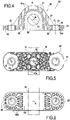
- FIGS 2 to 6 show such a bearing 20 mounted on a section 13 of the stabilizer bar 10.
- the bearing 20 comprises a flange 30 and an elastomer layer 59.
- the flange 30 has a general U shape and comprises two retaining lugs 31 connected by a hoop 35 so as to form a groove 36.
- the flange 30 is symmetrical with respect to its main axis A which more broadly constitutes the main axis of the landing 20.
- Each retaining lug 31 extends laterally from the base of the hoop 35, perpendicular to the main axis A.
- Each retaining lug 31 has a bearing surface 32, forming the bearing surface of the strap 30 and more widely of the bearing 20, and a through bore 33, of axis C perpendicular to the bearing surface 32 and therefore parallel to the main axis A.
- Each bore 33 is provided with a metal sleeve 34.
- the groove 36 in the general shape of a U, is also symmetrical with respect to the main axis A. It has a semi-cylindrical bottom portion, forming a cradle portion 37, flanked by two flat side walls 38 opening onto the support surface 32 of the flange 30.
- the semi-cylindrical cradle portion 37 is directed along an axis B orthogonal to the axis A and corresponding to the direction of extension of the stabilizer bar 10 when the bearing 20 is mounted.
- the flange 30 is made by molding and injection of polyamide 66 reinforced with glass fibers. These glass fibers are short fibers, the length of which is between 3 and 3.2 mm for a diameter of between 0.2 and 0.25 mm. These fibers are treated by sizing to allow good wetting of the fibers and then mixed with the polyamide matrix up to 30 to 50% by mass of the final material.
- the metal sleeves 34 are for their part inserted into the mold of the flange 30 before the injection of the thermoplastic material; annular reliefs 34a make it possible to block their positions within the flange 30 once the material has solidified.
- the flange 30 comprises numerous cylindrical cells 41, 42 extending parallel to the main axis A of the flange 30.
- the hoop 35 comprises a first set of cells 41 organized symmetrically with respect to the main axis A.
- the walls 41a separating these cells 41 extend either radially with respect to the main axis A, or along curves centered on the main axis A and preferably substantially circumferential with respect to the main axis A.
- These cells 41 are open on the outer surface of the hoop 35 and closed at the level of the groove 36.
- the corners of these cells 41 are rounded, a fillet being provided between each side wall of the cells 41, so as to facilitate the passage and orientation of the reinforcing fibers in the flange 30 during injection.
- Each retaining lug 31 also includes a second set of cells 42 organized symmetrically with respect to the axis C of the bore 33 of the retaining lug 31 in question.
- the walls 42a separating these cells 42 extend radially with respect to the axis C of the bore 33.
- These cells 42 are open on the bearing surface 32 of the retaining lug 31 and closed at the level of its opposite surface.
- the corners of these cells 42 are rounded, a fillet being provided between each side wall of the cells 42.
- the stabilizer assembly 1 is then assembled as follows. Once the flange 30 has been manufactured by molding and injection, the flange 30 is passed around the stabilizer bar 10. In particular, we note on the FIG. 2 and 4 that the section 13 of the stabilizer bar 10 is received entirely in the groove 36 of the flange 10, that is to say that the groove 36 completely surrounds the stabilizer bar 10.
- the stabilizer bar 10 may have undergone a preparation treatment.
- the stabilizer bar 10 may have undergone a flaming step during which the zone or zones to receive the bearing 20 are locally heated for approximately 6 s using a torch flame, for example a gas torch, propane, butane or acetylene to name but a few examples.
- a torch flame for example a gas torch, propane, butane or acetylene to name but a few examples.
- the bar is turned around its axis, for example by hand.
- This assembly is then placed in a mold so that the stabilizer bar 10 extends within the flange 30 along the axis B leaving a continuous and constant clearance between the stabilizer bar 10 and the cradle portion 37 of the flange 30.
- Rubber is then injected into the mold so as to fill the space of the groove 63 left all around the stabilizer bar 10, thus forming the elastomeric layer 59.
- the elastomeric layer 59 completely surrounds, in a single piece and continuously, that is to say in a single part without a break, the section 13 of the stabilizer bar 10.
- the elastomeric layer 59 thus obtained is then vulcanized by so as to secure the stabilizer bar 10 within the flange 30: the bearing 20 is thus assembled and the same operation can be carried out for the second bearing 20.
- the stabilizer assembly 1 thus assembled can then be mounted on the chassis of the vehicle by pressing the bearing surface 32 of the bearing 10 onto the chassis and by screwing the bearing 20 onto the chassis using two screws passing through the bores 33 retaining lugs 32.
Landscapes
- Engineering & Computer Science (AREA)
- Mechanical Engineering (AREA)
- General Engineering & Computer Science (AREA)
- Vehicle Body Suspensions (AREA)
- Springs (AREA)
Claims (7)
- Verfahren zur Herstellung einer Stabilisatoranordnung für ein Fahrzeug, umfassend die folgenden Schritte:Bereitstellen einer Stabilisatorstange (10),Bereitstellen eines Flansches (30) aus Kunststoffmaterial, umfassend wenigstens einen Halteabschnitt (31) und eine Hohlkehle (36), die einen Lagerungsabschnitt (37) enthält,Einsetzen der Stabilisatorstange (10) in die Hohlkehle (36) des Flansches (30),Einspritzen eines Elastomers in die Hohlkehle (36) des Flansches (30) an der Schnittstelle mit der Stabilisatorstange (10), um den rund um die Stabilisatorstange (10) herum verbliebenen Raum der Hohlkehle (36) zu füllen, und Erhalten einer Elastomerschicht (59) im Bereich dieser Schnittstelle, wobei die Elastomerschicht (59) die Stabilisatorstange (10) vollständig umgibt, undVulkanisieren der Elastomerschicht (59).
- Herstellungsverfahren nach Anspruch 1, bei dem der Flansch (30) aus thermoplastischem Material, vorzugsweise auf Basis von Polyamid gefertigt ist.
- Herstellungsverfahren nach Anspruch 1 oder 2, bei dem der Flansch (30) aus einem faserverstärkten Material gefertigt ist.
- Herstellungsverfahren nach einem der Ansprüche 1 bis 3, bei dem die Elastomerschicht (59) auf Basis von vulkanisiertem Gummi hergestellt ist.
- Herstellungsverfahren nach einem der Ansprüche 1 bis 4, bei dem der Flansch (30) eine Wabenstruktur (41, 42) aufweist.
- Herstellungsverfahren nach Anspruch 5, bei dem die Zellen (41, 42) des Flansches (30) parallel sind und entlang einer Hauptrichtung (A) des Flansches (30) orthogonal zur Erstreckungsrichtung (B) des Stabilisators (10) verlaufen.
- Herstellungsverfahren nach Anspruch 6, bei dem wenigstens bestimmte Wände (41a, 42a), welche die Zellen (41, 42) des Flansches (30) trennen, sich in im Wesentlichen radialen und/oder tangentialen Ebenen in Bezug auf die Hauptachse (A) des Flansches (30) erstrecken.
Applications Claiming Priority (2)
| Application Number | Priority Date | Filing Date | Title |
|---|---|---|---|
| FR1757412A FR3069807B1 (fr) | 2017-08-02 | 2017-08-02 | Ensemble stabilisateur pour vehicule |
| PCT/FR2018/051977 WO2019025726A1 (fr) | 2017-08-02 | 2018-08-01 | Ensemble stabilisateur pour vehicule |
Publications (2)
| Publication Number | Publication Date |
|---|---|
| EP3661774A1 EP3661774A1 (de) | 2020-06-10 |
| EP3661774B1 true EP3661774B1 (de) | 2022-10-05 |
Family
ID=59811665
Family Applications (1)
| Application Number | Title | Priority Date | Filing Date |
|---|---|---|---|
| EP18758945.2A Active EP3661774B1 (de) | 2017-08-02 | 2018-08-01 | Herstellungsverfahren für eine stabilisatoranordnung für ein fahrzeug |
Country Status (5)
| Country | Link |
|---|---|
| US (1) | US11584188B2 (de) |
| EP (1) | EP3661774B1 (de) |
| JP (1) | JP2020529364A (de) |
| FR (1) | FR3069807B1 (de) |
| WO (1) | WO2019025726A1 (de) |
Families Citing this family (1)
| Publication number | Priority date | Publication date | Assignee | Title |
|---|---|---|---|---|
| US11642932B2 (en) * | 2021-10-08 | 2023-05-09 | GM Global Technology Operations LLC | Bushing assembly for a stabilizer bar of a vehicle |
Citations (1)
| Publication number | Priority date | Publication date | Assignee | Title |
|---|---|---|---|---|
| US5588209A (en) * | 1994-05-04 | 1996-12-31 | The Tempered Spring Company Limited | Method and apparatus to manufacture stabilizer bars |
Family Cites Families (12)
| Publication number | Priority date | Publication date | Assignee | Title |
|---|---|---|---|---|
| US5208981A (en) * | 1989-01-19 | 1993-05-11 | Bela Puzsik | Drive shaft support |
| DE10006329C1 (de) * | 2000-02-12 | 2001-08-09 | Joern Gmbh | Gelenklager, insbesondere Stabilisatorlager für ein Fahrzeug |
| KR20120099622A (ko) * | 2009-06-25 | 2012-09-11 | 슈네간스 게엠베하 | 차축 스태빌라이저의 베어링을 위한 고정 장치 |
| FR2965239B1 (fr) * | 2010-09-24 | 2014-02-28 | Peugeot Citroen Automobiles Sa | Berceau destine a etre solidarise a la structure avant d'un vehicule comportant une corne et corne pour un tel berceau |
| DE102012208156A1 (de) * | 2012-05-15 | 2013-11-21 | Bayerische Motoren Werke Aktiengesellschaft | Lagerung eines Stabilisators im Fahrwerk eines zweispurigen Kraftfahrzeugs |
| DE102014217839A1 (de) * | 2014-09-05 | 2016-03-10 | Bayerische Motoren Werke Aktiengesellschaft | Stabilisatorlager für ein zweispuriges Fahrzeug |
| DE102015008952B3 (de) * | 2015-07-10 | 2016-07-28 | Audi Ag | Schwingungstilger zur Reduktion von Schwingungen am Fahrwerk eines Kraftfahrzeugs |
| DE202016100149U1 (de) * | 2016-01-14 | 2016-02-29 | Vorwerk Autotec Gmbh & Co.Kg | Lager zur Anlenkung eines Fahrwerk-Stabilisators an einem Kraftfahrzeug |
| KR101846533B1 (ko) * | 2016-11-24 | 2018-04-06 | 주식회사 세명기업 | 브래킷 일체형 스태빌라이저 바 부싱 조립체 및 이를 이용한 스태빌라이저 바 조립체 |
| FR3069897B1 (fr) * | 2017-08-02 | 2019-12-27 | Sogefi Suspensions | Palier pour barre stabilisatrice |
| FR3069898B1 (fr) * | 2017-08-02 | 2019-12-27 | Sogefi Suspensions | Palier pour barre stabilisatrice muni d'une contreplaque |
| DE102019003884A1 (de) * | 2019-06-03 | 2020-12-03 | Sumitomo Riko Company Limited | Halterung für einen Fahrzeugstabilisator, Fahrzeugstabilisator und Verfahren |
-
2017
- 2017-08-02 FR FR1757412A patent/FR3069807B1/fr active Active
-
2018
- 2018-08-01 EP EP18758945.2A patent/EP3661774B1/de active Active
- 2018-08-01 WO PCT/FR2018/051977 patent/WO2019025726A1/fr unknown
- 2018-08-01 JP JP2020528516A patent/JP2020529364A/ja not_active Withdrawn
- 2018-08-01 US US16/635,587 patent/US11584188B2/en active Active
Patent Citations (1)
| Publication number | Priority date | Publication date | Assignee | Title |
|---|---|---|---|---|
| US5588209A (en) * | 1994-05-04 | 1996-12-31 | The Tempered Spring Company Limited | Method and apparatus to manufacture stabilizer bars |
Also Published As
| Publication number | Publication date |
|---|---|
| WO2019025726A1 (fr) | 2019-02-07 |
| US20200238784A1 (en) | 2020-07-30 |
| FR3069807B1 (fr) | 2021-02-12 |
| US11584188B2 (en) | 2023-02-21 |
| JP2020529364A (ja) | 2020-10-08 |
| FR3069807A1 (fr) | 2019-02-08 |
| EP3661774A1 (de) | 2020-06-10 |
Similar Documents
| Publication | Publication Date | Title |
|---|---|---|
| EP3661775B1 (de) | Lager für stabilisator mit einer trägerplatte | |
| FR3019866A1 (fr) | Dispositif de poulie pour courroie ou chaine, procede de fabrication d'un arbre creux pour un tel dispositif et procede d'assemblage d'un tel dispositif | |
| FR2890715A1 (fr) | Palier a douille elastomere et procede de fabrication. | |
| WO2019025728A1 (fr) | Palier pour barre stabilisatrice | |
| FR2952853A1 (fr) | Roue composite, notamment pour un cycle, et procede de fabrication d'une telle roue | |
| FR2967965A1 (fr) | Ensemble de structure pour vehicule automobile comprenant une coupelle de support de systeme de suspension et une paroi de passage de roue | |
| EP0307288A1 (de) | Mit Buchsen versehene Kupplungsvorrichtung und an einer Rotornabe damit verbundenes Rotorblatt | |
| FR3086331A1 (fr) | Suspente d’echappement renforcee, et procede de fabrication de celle-ci | |
| FR2802863A1 (fr) | Palier intermediaire pour une ligne d'arbre d'entrainement d'un vehicule automobile | |
| FR2955524A1 (fr) | Procede de fabrication d'un bras pour structure articulee tel qu'un balancier equipant une structure d'atterrisseu d'aeronef. | |
| CA2603272C (fr) | Anneau de verrouillage dans un ensemble de montage d'un pneumatique sur un moyeu de vehicule | |
| EP0660006A1 (de) | Dynamisches Resonatorelement und sein Montageverfahren | |
| EP3661774B1 (de) | Herstellungsverfahren für eine stabilisatoranordnung für ein fahrzeug | |
| EP1868824B1 (de) | System zur arretierung eines montagerings an einer fahrzeugnabe | |
| FR2817606A1 (fr) | Tuyau flexible a bride de raccordement et procede d'obtention d'un tel tuyau | |
| EP3152027B1 (de) | Verfahren zur herstellung eines zahnrades mit verstärkungsreifen | |
| WO2011161370A1 (fr) | Dispositif et procédé d'assemblage de deux éléments coques en matériau composite | |
| FR2859662A1 (fr) | Methode pour alleger un dispositif de roulage a plat de roue de vehicule automobile et dispositif ainsi obtenu | |
| WO2020049261A1 (fr) | Bague pour corps cylindrique | |
| FR3134542A1 (fr) | Bride pour palier de barre stabilisatrice | |
| FR3006393A1 (fr) | Procede d'assemblage de tubes par emmanchement colle et traverse de planche de bord obtenue par un tel procede | |
| FR3026151A1 (fr) | Dispositif d'assemblage a ecrou-barillet, ensemble structurel d'aeronef comprenant un tel dispositif, et procede d'assemblage correspondant | |
| BE1026065B1 (fr) | Roue de véhicule comprenant des paires de rayons sous tension | |
| EP4293248A1 (de) | Schwingungsdämpfendes lager und fahrzeug mit einem solchen schwingungsdämpfer | |
| EP1478860A1 (de) | Verfahren zum befestigen eines aus elastomerem material bestehenden ringförmigen kupplungsteils zwischen zwei ineinandergesteckten rohren und sich aus dem verfahren ausgebende anordnung |
Legal Events
| Date | Code | Title | Description |
|---|---|---|---|
| STAA | Information on the status of an ep patent application or granted ep patent |
Free format text: STATUS: UNKNOWN |
|
| STAA | Information on the status of an ep patent application or granted ep patent |
Free format text: STATUS: THE INTERNATIONAL PUBLICATION HAS BEEN MADE |
|
| PUAI | Public reference made under article 153(3) epc to a published international application that has entered the european phase |
Free format text: ORIGINAL CODE: 0009012 |
|
| STAA | Information on the status of an ep patent application or granted ep patent |
Free format text: STATUS: REQUEST FOR EXAMINATION WAS MADE |
|
| 17P | Request for examination filed |
Effective date: 20200225 |
|
| AK | Designated contracting states |
Kind code of ref document: A1 Designated state(s): AL AT BE BG CH CY CZ DE DK EE ES FI FR GB GR HR HU IE IS IT LI LT LU LV MC MK MT NL NO PL PT RO RS SE SI SK SM TR |
|
| AX | Request for extension of the european patent |
Extension state: BA ME |
|
| DAV | Request for validation of the european patent (deleted) | ||
| DAX | Request for extension of the european patent (deleted) | ||
| STAA | Information on the status of an ep patent application or granted ep patent |
Free format text: STATUS: EXAMINATION IS IN PROGRESS |
|
| RIN1 | Information on inventor provided before grant (corrected) |
Inventor name: ACHTIOUI, TOURIA Inventor name: VILLETTE, MAUD Inventor name: BOUDIER, PASCAL Inventor name: RHEIN, JACKY |
|
| 17Q | First examination report despatched |
Effective date: 20210301 |
|
| GRAP | Despatch of communication of intention to grant a patent |
Free format text: ORIGINAL CODE: EPIDOSNIGR1 |
|
| STAA | Information on the status of an ep patent application or granted ep patent |
Free format text: STATUS: GRANT OF PATENT IS INTENDED |
|
| INTG | Intention to grant announced |
Effective date: 20220429 |
|
| GRAS | Grant fee paid |
Free format text: ORIGINAL CODE: EPIDOSNIGR3 |
|
| GRAA | (expected) grant |
Free format text: ORIGINAL CODE: 0009210 |
|
| STAA | Information on the status of an ep patent application or granted ep patent |
Free format text: STATUS: THE PATENT HAS BEEN GRANTED |
|
| AK | Designated contracting states |
Kind code of ref document: B1 Designated state(s): AL AT BE BG CH CY CZ DE DK EE ES FI FR GB GR HR HU IE IS IT LI LT LU LV MC MK MT NL NO PL PT RO RS SE SI SK SM TR |
|
| REG | Reference to a national code |
Ref country code: GB Ref legal event code: FG4D Free format text: NOT ENGLISH |
|
| REG | Reference to a national code |
Ref country code: CH Ref legal event code: EP |
|
| REG | Reference to a national code |
Ref country code: AT Ref legal event code: REF Ref document number: 1522541 Country of ref document: AT Kind code of ref document: T Effective date: 20221015 |
|
| REG | Reference to a national code |
Ref country code: IE Ref legal event code: FG4D Free format text: LANGUAGE OF EP DOCUMENT: FRENCH |
|
| REG | Reference to a national code |
Ref country code: DE Ref legal event code: R096 Ref document number: 602018041425 Country of ref document: DE |
|
| REG | Reference to a national code |
Ref country code: LT Ref legal event code: MG9D |
|
| REG | Reference to a national code |
Ref country code: NL Ref legal event code: MP Effective date: 20221005 |
|
| REG | Reference to a national code |
Ref country code: AT Ref legal event code: MK05 Ref document number: 1522541 Country of ref document: AT Kind code of ref document: T Effective date: 20221005 |
|
| PG25 | Lapsed in a contracting state [announced via postgrant information from national office to epo] |
Ref country code: NL Free format text: LAPSE BECAUSE OF FAILURE TO SUBMIT A TRANSLATION OF THE DESCRIPTION OR TO PAY THE FEE WITHIN THE PRESCRIBED TIME-LIMIT Effective date: 20221005 |
|
| PG25 | Lapsed in a contracting state [announced via postgrant information from national office to epo] |
Ref country code: SE Free format text: LAPSE BECAUSE OF FAILURE TO SUBMIT A TRANSLATION OF THE DESCRIPTION OR TO PAY THE FEE WITHIN THE PRESCRIBED TIME-LIMIT Effective date: 20221005 Ref country code: PT Free format text: LAPSE BECAUSE OF FAILURE TO SUBMIT A TRANSLATION OF THE DESCRIPTION OR TO PAY THE FEE WITHIN THE PRESCRIBED TIME-LIMIT Effective date: 20230206 Ref country code: NO Free format text: LAPSE BECAUSE OF FAILURE TO SUBMIT A TRANSLATION OF THE DESCRIPTION OR TO PAY THE FEE WITHIN THE PRESCRIBED TIME-LIMIT Effective date: 20230105 Ref country code: LT Free format text: LAPSE BECAUSE OF FAILURE TO SUBMIT A TRANSLATION OF THE DESCRIPTION OR TO PAY THE FEE WITHIN THE PRESCRIBED TIME-LIMIT Effective date: 20221005 Ref country code: FI Free format text: LAPSE BECAUSE OF FAILURE TO SUBMIT A TRANSLATION OF THE DESCRIPTION OR TO PAY THE FEE WITHIN THE PRESCRIBED TIME-LIMIT Effective date: 20221005 Ref country code: ES Free format text: LAPSE BECAUSE OF FAILURE TO SUBMIT A TRANSLATION OF THE DESCRIPTION OR TO PAY THE FEE WITHIN THE PRESCRIBED TIME-LIMIT Effective date: 20221005 Ref country code: AT Free format text: LAPSE BECAUSE OF FAILURE TO SUBMIT A TRANSLATION OF THE DESCRIPTION OR TO PAY THE FEE WITHIN THE PRESCRIBED TIME-LIMIT Effective date: 20221005 |
|
| PG25 | Lapsed in a contracting state [announced via postgrant information from national office to epo] |
Ref country code: RS Free format text: LAPSE BECAUSE OF FAILURE TO SUBMIT A TRANSLATION OF THE DESCRIPTION OR TO PAY THE FEE WITHIN THE PRESCRIBED TIME-LIMIT Effective date: 20221005 Ref country code: PL Free format text: LAPSE BECAUSE OF FAILURE TO SUBMIT A TRANSLATION OF THE DESCRIPTION OR TO PAY THE FEE WITHIN THE PRESCRIBED TIME-LIMIT Effective date: 20221005 Ref country code: LV Free format text: LAPSE BECAUSE OF FAILURE TO SUBMIT A TRANSLATION OF THE DESCRIPTION OR TO PAY THE FEE WITHIN THE PRESCRIBED TIME-LIMIT Effective date: 20221005 Ref country code: IS Free format text: LAPSE BECAUSE OF FAILURE TO SUBMIT A TRANSLATION OF THE DESCRIPTION OR TO PAY THE FEE WITHIN THE PRESCRIBED TIME-LIMIT Effective date: 20230205 Ref country code: HR Free format text: LAPSE BECAUSE OF FAILURE TO SUBMIT A TRANSLATION OF THE DESCRIPTION OR TO PAY THE FEE WITHIN THE PRESCRIBED TIME-LIMIT Effective date: 20221005 Ref country code: GR Free format text: LAPSE BECAUSE OF FAILURE TO SUBMIT A TRANSLATION OF THE DESCRIPTION OR TO PAY THE FEE WITHIN THE PRESCRIBED TIME-LIMIT Effective date: 20230106 |
|
| REG | Reference to a national code |
Ref country code: DE Ref legal event code: R097 Ref document number: 602018041425 Country of ref document: DE |
|
| PG25 | Lapsed in a contracting state [announced via postgrant information from national office to epo] |
Ref country code: SM Free format text: LAPSE BECAUSE OF FAILURE TO SUBMIT A TRANSLATION OF THE DESCRIPTION OR TO PAY THE FEE WITHIN THE PRESCRIBED TIME-LIMIT Effective date: 20221005 Ref country code: RO Free format text: LAPSE BECAUSE OF FAILURE TO SUBMIT A TRANSLATION OF THE DESCRIPTION OR TO PAY THE FEE WITHIN THE PRESCRIBED TIME-LIMIT Effective date: 20221005 Ref country code: EE Free format text: LAPSE BECAUSE OF FAILURE TO SUBMIT A TRANSLATION OF THE DESCRIPTION OR TO PAY THE FEE WITHIN THE PRESCRIBED TIME-LIMIT Effective date: 20221005 Ref country code: DK Free format text: LAPSE BECAUSE OF FAILURE TO SUBMIT A TRANSLATION OF THE DESCRIPTION OR TO PAY THE FEE WITHIN THE PRESCRIBED TIME-LIMIT Effective date: 20221005 Ref country code: CZ Free format text: LAPSE BECAUSE OF FAILURE TO SUBMIT A TRANSLATION OF THE DESCRIPTION OR TO PAY THE FEE WITHIN THE PRESCRIBED TIME-LIMIT Effective date: 20221005 |
|
| PLBE | No opposition filed within time limit |
Free format text: ORIGINAL CODE: 0009261 |
|
| STAA | Information on the status of an ep patent application or granted ep patent |
Free format text: STATUS: NO OPPOSITION FILED WITHIN TIME LIMIT |
|
| PG25 | Lapsed in a contracting state [announced via postgrant information from national office to epo] |
Ref country code: SK Free format text: LAPSE BECAUSE OF FAILURE TO SUBMIT A TRANSLATION OF THE DESCRIPTION OR TO PAY THE FEE WITHIN THE PRESCRIBED TIME-LIMIT Effective date: 20221005 Ref country code: AL Free format text: LAPSE BECAUSE OF FAILURE TO SUBMIT A TRANSLATION OF THE DESCRIPTION OR TO PAY THE FEE WITHIN THE PRESCRIBED TIME-LIMIT Effective date: 20221005 |
|
| 26N | No opposition filed |
Effective date: 20230706 |
|
| PG25 | Lapsed in a contracting state [announced via postgrant information from national office to epo] |
Ref country code: SI Free format text: LAPSE BECAUSE OF FAILURE TO SUBMIT A TRANSLATION OF THE DESCRIPTION OR TO PAY THE FEE WITHIN THE PRESCRIBED TIME-LIMIT Effective date: 20221005 |
|
| PG25 | Lapsed in a contracting state [announced via postgrant information from national office to epo] |
Ref country code: MC Free format text: LAPSE BECAUSE OF FAILURE TO SUBMIT A TRANSLATION OF THE DESCRIPTION OR TO PAY THE FEE WITHIN THE PRESCRIBED TIME-LIMIT Effective date: 20221005 |
|
| REG | Reference to a national code |
Ref country code: CH Ref legal event code: PL |
|
| PG25 | Lapsed in a contracting state [announced via postgrant information from national office to epo] |
Ref country code: MC Free format text: LAPSE BECAUSE OF FAILURE TO SUBMIT A TRANSLATION OF THE DESCRIPTION OR TO PAY THE FEE WITHIN THE PRESCRIBED TIME-LIMIT Effective date: 20221005 |
|
| PG25 | Lapsed in a contracting state [announced via postgrant information from national office to epo] |
Ref country code: LU Free format text: LAPSE BECAUSE OF NON-PAYMENT OF DUE FEES Effective date: 20230801 |
|
| PG25 | Lapsed in a contracting state [announced via postgrant information from national office to epo] |
Ref country code: LU Free format text: LAPSE BECAUSE OF NON-PAYMENT OF DUE FEES Effective date: 20230801 Ref country code: CH Free format text: LAPSE BECAUSE OF NON-PAYMENT OF DUE FEES Effective date: 20230831 |
|
| REG | Reference to a national code |
Ref country code: BE Ref legal event code: MM Effective date: 20230831 |
|
| REG | Reference to a national code |
Ref country code: IE Ref legal event code: MM4A |
|
| PG25 | Lapsed in a contracting state [announced via postgrant information from national office to epo] |
Ref country code: IT Free format text: LAPSE BECAUSE OF FAILURE TO SUBMIT A TRANSLATION OF THE DESCRIPTION OR TO PAY THE FEE WITHIN THE PRESCRIBED TIME-LIMIT Effective date: 20221005 |
|
| PG25 | Lapsed in a contracting state [announced via postgrant information from national office to epo] |
Ref country code: IE Free format text: LAPSE BECAUSE OF NON-PAYMENT OF DUE FEES Effective date: 20230801 |
|
| PG25 | Lapsed in a contracting state [announced via postgrant information from national office to epo] |
Ref country code: IE Free format text: LAPSE BECAUSE OF NON-PAYMENT OF DUE FEES Effective date: 20230801 |
|
| PG25 | Lapsed in a contracting state [announced via postgrant information from national office to epo] |
Ref country code: BE Free format text: LAPSE BECAUSE OF NON-PAYMENT OF DUE FEES Effective date: 20230831 |
|
| PGFP | Annual fee paid to national office [announced via postgrant information from national office to epo] |
Ref country code: DE Payment date: 20240806 Year of fee payment: 7 |
|
| PGFP | Annual fee paid to national office [announced via postgrant information from national office to epo] |
Ref country code: GB Payment date: 20240823 Year of fee payment: 7 |
|
| PGFP | Annual fee paid to national office [announced via postgrant information from national office to epo] |
Ref country code: FR Payment date: 20240820 Year of fee payment: 7 |