EP3661436B1 - Système d'introduction avec capacités d'extension - Google Patents
Système d'introduction avec capacités d'extension Download PDFInfo
- Publication number
- EP3661436B1 EP3661436B1 EP18755620.4A EP18755620A EP3661436B1 EP 3661436 B1 EP3661436 B1 EP 3661436B1 EP 18755620 A EP18755620 A EP 18755620A EP 3661436 B1 EP3661436 B1 EP 3661436B1
- Authority
- EP
- European Patent Office
- Prior art keywords
- sheath
- introducer
- medical device
- delivery system
- introducer sheath
- Prior art date
- Legal status (The legal status is an assumption and is not a legal conclusion. Google has not performed a legal analysis and makes no representation as to the accuracy of the status listed.)
- Active
Links
- 239000007943 implant Substances 0.000 claims description 39
- 210000003709 heart valve Anatomy 0.000 claims description 12
- 210000000038 chest Anatomy 0.000 description 37
- 239000000463 material Substances 0.000 description 18
- 238000000034 method Methods 0.000 description 14
- 210000005166 vasculature Anatomy 0.000 description 9
- 238000003780 insertion Methods 0.000 description 8
- 230000037431 insertion Effects 0.000 description 8
- 238000011282 treatment Methods 0.000 description 7
- 238000013461 design Methods 0.000 description 6
- PXHVJJICTQNCMI-UHFFFAOYSA-N Nickel Chemical compound [Ni] PXHVJJICTQNCMI-UHFFFAOYSA-N 0.000 description 5
- 210000003484 anatomy Anatomy 0.000 description 5
- 210000001765 aortic valve Anatomy 0.000 description 5
- 238000004519 manufacturing process Methods 0.000 description 5
- 229910001000 nickel titanium Inorganic materials 0.000 description 5
- 229920000642 polymer Polymers 0.000 description 5
- 238000002560 therapeutic procedure Methods 0.000 description 5
- 230000002950 deficient Effects 0.000 description 4
- HLXZNVUGXRDIFK-UHFFFAOYSA-N nickel titanium Chemical compound [Ti].[Ti].[Ti].[Ti].[Ti].[Ti].[Ti].[Ti].[Ti].[Ti].[Ti].[Ni].[Ni].[Ni].[Ni].[Ni].[Ni].[Ni].[Ni].[Ni].[Ni].[Ni].[Ni].[Ni].[Ni] HLXZNVUGXRDIFK-UHFFFAOYSA-N 0.000 description 4
- BASFCYQUMIYNBI-UHFFFAOYSA-N platinum Chemical compound [Pt] BASFCYQUMIYNBI-UHFFFAOYSA-N 0.000 description 4
- 239000004952 Polyamide Substances 0.000 description 3
- 229920002614 Polyether block amide Polymers 0.000 description 3
- 210000000748 cardiovascular system Anatomy 0.000 description 3
- 210000004351 coronary vessel Anatomy 0.000 description 3
- 208000014674 injury Diseases 0.000 description 3
- 239000012528 membrane Substances 0.000 description 3
- 210000004115 mitral valve Anatomy 0.000 description 3
- 229920002647 polyamide Polymers 0.000 description 3
- 230000008439 repair process Effects 0.000 description 3
- 229910001220 stainless steel Inorganic materials 0.000 description 3
- 239000010936 titanium Substances 0.000 description 3
- RTZKZFJDLAIYFH-UHFFFAOYSA-N Diethyl ether Chemical compound CCOCC RTZKZFJDLAIYFH-UHFFFAOYSA-N 0.000 description 2
- 239000004812 Fluorinated ethylene propylene Substances 0.000 description 2
- 229920000106 Liquid crystal polymer Polymers 0.000 description 2
- 239000004977 Liquid-crystal polymers (LCPs) Substances 0.000 description 2
- KDLHZDBZIXYQEI-UHFFFAOYSA-N Palladium Chemical compound [Pd] KDLHZDBZIXYQEI-UHFFFAOYSA-N 0.000 description 2
- 239000004696 Poly ether ether ketone Substances 0.000 description 2
- 239000004697 Polyetherimide Substances 0.000 description 2
- 239000004642 Polyimide Substances 0.000 description 2
- RTAQQCXQSZGOHL-UHFFFAOYSA-N Titanium Chemical compound [Ti] RTAQQCXQSZGOHL-UHFFFAOYSA-N 0.000 description 2
- 208000027418 Wounds and injury Diseases 0.000 description 2
- 239000000919 ceramic Substances 0.000 description 2
- 239000002131 composite material Substances 0.000 description 2
- 230000008878 coupling Effects 0.000 description 2
- 238000010168 coupling process Methods 0.000 description 2
- 238000005859 coupling reaction Methods 0.000 description 2
- 230000006378 damage Effects 0.000 description 2
- 210000001035 gastrointestinal tract Anatomy 0.000 description 2
- 238000002844 melting Methods 0.000 description 2
- 230000008018 melting Effects 0.000 description 2
- 229910052751 metal Inorganic materials 0.000 description 2
- 239000002184 metal Substances 0.000 description 2
- 229910001092 metal group alloy Inorganic materials 0.000 description 2
- 210000000214 mouth Anatomy 0.000 description 2
- 229910052759 nickel Inorganic materials 0.000 description 2
- 229920009441 perflouroethylene propylene Polymers 0.000 description 2
- 210000003800 pharynx Anatomy 0.000 description 2
- 229910052697 platinum Inorganic materials 0.000 description 2
- 229920002530 polyetherether ketone Polymers 0.000 description 2
- 229920001601 polyetherimide Polymers 0.000 description 2
- -1 polyethylene Polymers 0.000 description 2
- 229920001721 polyimide Polymers 0.000 description 2
- 229920001343 polytetrafluoroethylene Polymers 0.000 description 2
- 239000004810 polytetrafluoroethylene Substances 0.000 description 2
- 238000000926 separation method Methods 0.000 description 2
- 239000010935 stainless steel Substances 0.000 description 2
- 239000000126 substance Substances 0.000 description 2
- 238000001356 surgical procedure Methods 0.000 description 2
- 229910052719 titanium Inorganic materials 0.000 description 2
- 229910000014 Bismuth subcarbonate Inorganic materials 0.000 description 1
- 229910000531 Co alloy Inorganic materials 0.000 description 1
- 229920006055 Durethan® Polymers 0.000 description 1
- 229910000640 Fe alloy Inorganic materials 0.000 description 1
- 229920000339 Marlex Polymers 0.000 description 1
- 239000004698 Polyethylene Substances 0.000 description 1
- 229910001080 W alloy Inorganic materials 0.000 description 1
- HZEWFHLRYVTOIW-UHFFFAOYSA-N [Ti].[Ni] Chemical compound [Ti].[Ni] HZEWFHLRYVTOIW-UHFFFAOYSA-N 0.000 description 1
- 229910045601 alloy Inorganic materials 0.000 description 1
- 239000000956 alloy Substances 0.000 description 1
- 238000002399 angioplasty Methods 0.000 description 1
- 238000013459 approach Methods 0.000 description 1
- 230000004888 barrier function Effects 0.000 description 1
- 230000009286 beneficial effect Effects 0.000 description 1
- MGLUJXPJRXTKJM-UHFFFAOYSA-L bismuth subcarbonate Chemical compound O=[Bi]OC(=O)O[Bi]=O MGLUJXPJRXTKJM-UHFFFAOYSA-L 0.000 description 1
- 229940036358 bismuth subcarbonate Drugs 0.000 description 1
- 239000000788 chromium alloy Substances 0.000 description 1
- BIJOYKCOMBZXAE-UHFFFAOYSA-N chromium iron nickel Chemical compound [Cr].[Fe].[Ni] BIJOYKCOMBZXAE-UHFFFAOYSA-N 0.000 description 1
- 210000001072 colon Anatomy 0.000 description 1
- 230000001079 digestive effect Effects 0.000 description 1
- 201000010099 disease Diseases 0.000 description 1
- 208000037265 diseases, disorders, signs and symptoms Diseases 0.000 description 1
- 230000000694 effects Effects 0.000 description 1
- 229920006351 engineering plastic Polymers 0.000 description 1
- HQQADJVZYDDRJT-UHFFFAOYSA-N ethene;prop-1-ene Chemical group C=C.CC=C HQQADJVZYDDRJT-UHFFFAOYSA-N 0.000 description 1
- 229920002313 fluoropolymer Polymers 0.000 description 1
- 239000004811 fluoropolymer Substances 0.000 description 1
- 238000002594 fluoroscopy Methods 0.000 description 1
- 230000006870 function Effects 0.000 description 1
- PCHJSUWPFVWCPO-UHFFFAOYSA-N gold Chemical compound [Au] PCHJSUWPFVWCPO-UHFFFAOYSA-N 0.000 description 1
- 229910052737 gold Inorganic materials 0.000 description 1
- 239000010931 gold Substances 0.000 description 1
- 230000036541 health Effects 0.000 description 1
- 229920001903 high density polyethylene Polymers 0.000 description 1
- 239000004700 high-density polyethylene Substances 0.000 description 1
- 238000003384 imaging method Methods 0.000 description 1
- 238000002513 implantation Methods 0.000 description 1
- PNDPGZBMCMUPRI-UHFFFAOYSA-N iodine Chemical compound II PNDPGZBMCMUPRI-UHFFFAOYSA-N 0.000 description 1
- 210000002429 large intestine Anatomy 0.000 description 1
- 229920000092 linear low density polyethylene Polymers 0.000 description 1
- 239000004707 linear low-density polyethylene Substances 0.000 description 1
- 210000004072 lung Anatomy 0.000 description 1
- 230000007246 mechanism Effects 0.000 description 1
- 239000000155 melt Substances 0.000 description 1
- 239000007769 metal material Substances 0.000 description 1
- 150000002739 metals Chemical class 0.000 description 1
- 238000012986 modification Methods 0.000 description 1
- 230000004048 modification Effects 0.000 description 1
- 229910000623 nickel–chromium alloy Inorganic materials 0.000 description 1
- 229910052763 palladium Inorganic materials 0.000 description 1
- VPRUMANMDWQMNF-UHFFFAOYSA-N phenylethane boronic acid Chemical compound OB(O)CCC1=CC=CC=C1 VPRUMANMDWQMNF-UHFFFAOYSA-N 0.000 description 1
- 229920000728 polyester Polymers 0.000 description 1
- 229920000573 polyethylene Polymers 0.000 description 1
- 229920001296 polysiloxane Polymers 0.000 description 1
- 229920002635 polyurethane Polymers 0.000 description 1
- 239000004814 polyurethane Substances 0.000 description 1
- 230000008569 process Effects 0.000 description 1
- 238000011084 recovery Methods 0.000 description 1
- 210000000664 rectum Anatomy 0.000 description 1
- 210000002345 respiratory system Anatomy 0.000 description 1
- 210000000813 small intestine Anatomy 0.000 description 1
- 229910052715 tantalum Inorganic materials 0.000 description 1
- GUVRBAGPIYLISA-UHFFFAOYSA-N tantalum atom Chemical compound [Ta] GUVRBAGPIYLISA-UHFFFAOYSA-N 0.000 description 1
- 239000012815 thermoplastic material Substances 0.000 description 1
- 230000008733 trauma Effects 0.000 description 1
- WFKWXMTUELFFGS-UHFFFAOYSA-N tungsten Chemical compound [W] WFKWXMTUELFFGS-UHFFFAOYSA-N 0.000 description 1
- 229910052721 tungsten Inorganic materials 0.000 description 1
- 239000010937 tungsten Substances 0.000 description 1
Images


Classifications
-
- A—HUMAN NECESSITIES
- A61—MEDICAL OR VETERINARY SCIENCE; HYGIENE
- A61F—FILTERS IMPLANTABLE INTO BLOOD VESSELS; PROSTHESES; DEVICES PROVIDING PATENCY TO, OR PREVENTING COLLAPSING OF, TUBULAR STRUCTURES OF THE BODY, e.g. STENTS; ORTHOPAEDIC, NURSING OR CONTRACEPTIVE DEVICES; FOMENTATION; TREATMENT OR PROTECTION OF EYES OR EARS; BANDAGES, DRESSINGS OR ABSORBENT PADS; FIRST-AID KITS
- A61F2/00—Filters implantable into blood vessels; Prostheses, i.e. artificial substitutes or replacements for parts of the body; Appliances for connecting them with the body; Devices providing patency to, or preventing collapsing of, tubular structures of the body, e.g. stents
- A61F2/02—Prostheses implantable into the body
- A61F2/24—Heart valves ; Vascular valves, e.g. venous valves; Heart implants, e.g. passive devices for improving the function of the native valve or the heart muscle; Transmyocardial revascularisation [TMR] devices; Valves implantable in the body
- A61F2/2427—Devices for manipulating or deploying heart valves during implantation
- A61F2/2436—Deployment by retracting a sheath
-
- A—HUMAN NECESSITIES
- A61—MEDICAL OR VETERINARY SCIENCE; HYGIENE
- A61M—DEVICES FOR INTRODUCING MEDIA INTO, OR ONTO, THE BODY; DEVICES FOR TRANSDUCING BODY MEDIA OR FOR TAKING MEDIA FROM THE BODY; DEVICES FOR PRODUCING OR ENDING SLEEP OR STUPOR
- A61M25/00—Catheters; Hollow probes
- A61M25/0021—Catheters; Hollow probes characterised by the form of the tubing
- A61M25/0023—Catheters; Hollow probes characterised by the form of the tubing by the form of the lumen, e.g. cross-section, variable diameter
-
- A—HUMAN NECESSITIES
- A61—MEDICAL OR VETERINARY SCIENCE; HYGIENE
- A61B—DIAGNOSIS; SURGERY; IDENTIFICATION
- A61B17/00—Surgical instruments, devices or methods, e.g. tourniquets
- A61B17/34—Trocars; Puncturing needles
- A61B17/3417—Details of tips or shafts, e.g. grooves, expandable, bendable; Multiple coaxial sliding cannulas, e.g. for dilating
- A61B17/3421—Cannulas
- A61B17/3431—Cannulas being collapsible, e.g. made of thin flexible material
-
- A—HUMAN NECESSITIES
- A61—MEDICAL OR VETERINARY SCIENCE; HYGIENE
- A61B—DIAGNOSIS; SURGERY; IDENTIFICATION
- A61B17/00—Surgical instruments, devices or methods, e.g. tourniquets
- A61B17/34—Trocars; Puncturing needles
- A61B17/3417—Details of tips or shafts, e.g. grooves, expandable, bendable; Multiple coaxial sliding cannulas, e.g. for dilating
- A61B17/3421—Cannulas
- A61B17/3439—Cannulas with means for changing the inner diameter of the cannula, e.g. expandable
-
- A—HUMAN NECESSITIES
- A61—MEDICAL OR VETERINARY SCIENCE; HYGIENE
- A61B—DIAGNOSIS; SURGERY; IDENTIFICATION
- A61B17/00—Surgical instruments, devices or methods, e.g. tourniquets
- A61B17/34—Trocars; Puncturing needles
- A61B17/3468—Trocars; Puncturing needles for implanting or removing devices, e.g. prostheses, implants, seeds, wires
-
- A—HUMAN NECESSITIES
- A61—MEDICAL OR VETERINARY SCIENCE; HYGIENE
- A61F—FILTERS IMPLANTABLE INTO BLOOD VESSELS; PROSTHESES; DEVICES PROVIDING PATENCY TO, OR PREVENTING COLLAPSING OF, TUBULAR STRUCTURES OF THE BODY, e.g. STENTS; ORTHOPAEDIC, NURSING OR CONTRACEPTIVE DEVICES; FOMENTATION; TREATMENT OR PROTECTION OF EYES OR EARS; BANDAGES, DRESSINGS OR ABSORBENT PADS; FIRST-AID KITS
- A61F2/00—Filters implantable into blood vessels; Prostheses, i.e. artificial substitutes or replacements for parts of the body; Appliances for connecting them with the body; Devices providing patency to, or preventing collapsing of, tubular structures of the body, e.g. stents
- A61F2/02—Prostheses implantable into the body
- A61F2/24—Heart valves ; Vascular valves, e.g. venous valves; Heart implants, e.g. passive devices for improving the function of the native valve or the heart muscle; Transmyocardial revascularisation [TMR] devices; Valves implantable in the body
- A61F2/2427—Devices for manipulating or deploying heart valves during implantation
-
- A—HUMAN NECESSITIES
- A61—MEDICAL OR VETERINARY SCIENCE; HYGIENE
- A61F—FILTERS IMPLANTABLE INTO BLOOD VESSELS; PROSTHESES; DEVICES PROVIDING PATENCY TO, OR PREVENTING COLLAPSING OF, TUBULAR STRUCTURES OF THE BODY, e.g. STENTS; ORTHOPAEDIC, NURSING OR CONTRACEPTIVE DEVICES; FOMENTATION; TREATMENT OR PROTECTION OF EYES OR EARS; BANDAGES, DRESSINGS OR ABSORBENT PADS; FIRST-AID KITS
- A61F2/00—Filters implantable into blood vessels; Prostheses, i.e. artificial substitutes or replacements for parts of the body; Appliances for connecting them with the body; Devices providing patency to, or preventing collapsing of, tubular structures of the body, e.g. stents
- A61F2/95—Instruments specially adapted for placement or removal of stents or stent-grafts
- A61F2/962—Instruments specially adapted for placement or removal of stents or stent-grafts having an outer sleeve
- A61F2/97—Instruments specially adapted for placement or removal of stents or stent-grafts having an outer sleeve the outer sleeve being splittable
-
- A—HUMAN NECESSITIES
- A61—MEDICAL OR VETERINARY SCIENCE; HYGIENE
- A61M—DEVICES FOR INTRODUCING MEDIA INTO, OR ONTO, THE BODY; DEVICES FOR TRANSDUCING BODY MEDIA OR FOR TAKING MEDIA FROM THE BODY; DEVICES FOR PRODUCING OR ENDING SLEEP OR STUPOR
- A61M25/00—Catheters; Hollow probes
- A61M25/01—Introducing, guiding, advancing, emplacing or holding catheters
- A61M25/06—Body-piercing guide needles or the like
- A61M25/0662—Guide tubes
-
- A—HUMAN NECESSITIES
- A61—MEDICAL OR VETERINARY SCIENCE; HYGIENE
- A61M—DEVICES FOR INTRODUCING MEDIA INTO, OR ONTO, THE BODY; DEVICES FOR TRANSDUCING BODY MEDIA OR FOR TAKING MEDIA FROM THE BODY; DEVICES FOR PRODUCING OR ENDING SLEEP OR STUPOR
- A61M25/00—Catheters; Hollow probes
- A61M25/0021—Catheters; Hollow probes characterised by the form of the tubing
- A61M25/0023—Catheters; Hollow probes characterised by the form of the tubing by the form of the lumen, e.g. cross-section, variable diameter
- A61M2025/0024—Expandable catheters or sheaths
-
- A—HUMAN NECESSITIES
- A61—MEDICAL OR VETERINARY SCIENCE; HYGIENE
- A61M—DEVICES FOR INTRODUCING MEDIA INTO, OR ONTO, THE BODY; DEVICES FOR TRANSDUCING BODY MEDIA OR FOR TAKING MEDIA FROM THE BODY; DEVICES FOR PRODUCING OR ENDING SLEEP OR STUPOR
- A61M25/00—Catheters; Hollow probes
- A61M25/0043—Catheters; Hollow probes characterised by structural features
- A61M25/005—Catheters; Hollow probes characterised by structural features with embedded materials for reinforcement, e.g. wires, coils, braids
- A61M25/0051—Catheters; Hollow probes characterised by structural features with embedded materials for reinforcement, e.g. wires, coils, braids made from fenestrated or weakened tubing layer
Definitions
- the disclosure relates generally to medical devices and more particularly to medical devices that are adapted for use in percutaneous medical procedures.
- performing percutaneous medical procedures may require the insertion and/or maneuvering of relatively large medical devices through a patient's vasculature.
- inserting the medical device into the vasculature may result in undesirable forces being applied to the vessel walls or at the aortotomy during tracking.
- the medical device may make undesirable contact with one or more vessel walls. This interference may cause injury to the vessel as the medical device is navigated into calcified or diseased vessels. Therefore, in some instances an introducer system is utilized to position an introducer sheath into the vessel, whereby the introducer sheath is utilized to facilitate the insertion of medical devices into the vessel.
- Vessel trauma resulting from forces applied to the vessel wall by a medical device may be lessened by minimizing the size of the introducer system used to access the vessel and provide a prototective barrier from the delivery system at the aortotomy. Therefore, it may be desirable to design an introducer system having a reduced insertion profile, whether inserted distally or aligned towards the back end of the delivery system.
- the implant delivery system may be removed in conjunction with or independently of the introducer sheath, depending on post procedures that would necessitate use of an introducer system.
- WO 2016/164082 A1 discloses an expandable introducer sheath for passage of implant delivery catheters.
- the implant delivery system includes a catheter shaft having a distal end region and proximal end region, an implant coupled to the distal end region of the catheter shaft, a handle coupled to the proximal end region of the catheter shaft and an introducer sheath disposed along the catheter shaft.
- the introducer sheath includes an inner liner including a lumen and an expandable support member.
- the support member includes a plurality of ribs extending along a length of the support member.
- the introducer sheath further includes a sheath attached to at least a portion of the support member, wherein the support member is designed to shift from a first position to an expanded position.
- the introducer sheath is pre-loaded on the implant delivery system.
- the introducer sheath shifts to the expanded position as the distal end region of the catheter shaft is withdrawn through the introducer sheath.
- distal end region is designed to puncture into a body lumen.
- the expandable support member extends around at least a portion of the inner liner.
- the support member is positioned between the inner liner and the sheath.
- the plurality of ribs includes a first set of rib members and a second set of rib members, and wherein the first set of rib members interdigitate with the second set of rib members.
- the present invention is directed to an implant delivery system as set forth in the claims.
- references in the specification to "an embodiment”, “some examples”, “other examples”, etc., indicate that the embodiment described may include one or more particular features, structures, and/or characteristics. However, such recitations do not necessarily mean that all examples include the particular features, structures, and/or characteristics. Additionally, when particular features, structures, and/or characteristics are described in connection with one embodiment, it should be understood that such features, structures, and/or characteristics may also be used connection with other examples whether or not explicitly described unless clearly stated to the contrary.
- Some relatively common medical conditions may include or be the result of inefficiency, ineffectiveness, or complete failure of one or more of the valves within the heart.
- failure of the aortic valve or the mitral valve can have a serious effect on a human and could lead to serious health condition and/or death if not dealt with properly.
- Treatment of defective heart valves poses other challenges in that the treatment often requires the repair or outright replacement of the defective valve.
- Such therapies may be highly invasive to the patient.
- medical devices that may be used for delivering a medical device to a portion of the cardiovascular system in order to diagnose, treat, and/or repair the system.
- At least some of the medical devices disclosed herein may be used to deliver and implant a replacement heart valve (e.g., a replacement aortic valve, replacement mitral valve, etc.).
- a replacement heart valve e.g., a replacement aortic valve, replacement mitral valve, etc.
- the devices disclosed herein may deliver the replacement heart valve percutaneously and, thus, may be much less invasive to the patient.
- the devices disclosed herein may also provide a number of additional desirable features and benefits as described in more detail below.
- a medical device e.g., an implantable heart valve
- inserting a medical device into the vasculature may result in undesirable forces being applied to the vessel walls.
- a medical device e.g., an implantable heart valve
- it may make undesirable contact with one or more vessel walls. This interference may cause injury to the vessel as the medical device is navigated into calcified or diseased vessels. Therefore, in some instances an introducer system is utilized to position an introducer sheath into the vessel, whereby the introducer sheath is utilized to facilitate the insertion of medical device (e.g., an implantable heart valve) into the vessel.
- an introducer sheath along the shaft of a medical device delivery system (e.g., an implantable heart valve delivery system), whereby the distal portion of the delivery system is withdrawn through the expandable introducer sheath as the system is retracted out of the body.
- a medical device delivery system e.g., an implantable heart valve delivery system
- This configuration permits the introducer sheath to remain in an unexpanded configuration as the delivery system is advanced into a body lumen, while also permitting the introducer sheath to expanded in the body lumen after the delivery system has been withdrawn back through the introducer sheath.
- the expanded introducer sheath may then be utilized to advance other medical devices therethrough.
- the following examples disclose an intravascular medical device including an expandable introducer, whereby the introducer is designed to expand from a reduced profile, unexpanded configuration to an expanded configuration.
- a medical device system 10 may be used to deliver and/or deploy a variety of medical devices to a number of locations within the anatomy.
- the medical device system 10 may include a replacement heart valve delivery system (e.g., a replacement aortic valve delivery system) that can be used for percutaneous delivery of a medical implant 16, such as a replacement/prosthetic heart valve.
- the medical device system 10 may also be used for other interventions including valve repair, valvuloplasty, delivery of an implantable medical device (e.g., such as a stent, graft, etc.), and the like, or other similar interventions.
- an implantable medical device e.g., such as a stent, graft, etc.
- the medical device system 10 may generally be described as a catheter system that includes a shaft 12, an inner catheter (not shown) extending at least partially through a lumen of the shaft 12, and a medical implant 16 (e.g., a replacement heart valve implant) which may be coupled to the inner catheter and disposed within a lumen of the shaft 12 during delivery of the medical implant 16.
- the medical implant 16 is disposed along a distal portion 20 of the shaft 12.
- a medical device handle 17 is disposed at a proximal end 18 of the shaft 12 and/or the inner catheter and may include one or more actuation mechanisms associated therewith.
- one or more tubular members e.g., the shaft 12, the inner catheter, etc.
- the medical device handle 17 may be designed to manipulate the position of the shaft 12 relative to the inner catheter and/or aid in the deployment of the medical implant 16.
- the medical device system 10 may be advanced percutaneously through the vasculature to a position adjacent to an area of interest and/or a treatment location.
- the medical device system 10 may be advanced through the vasculature to a position adjacent to a defective native valve (e.g., aortic valve, mitral valve, etc.).
- a defective native valve e.g., aortic valve, mitral valve, etc.
- Alternative approaches to treat a defective aortic valve and/or other heart valve(s) are also contemplated with the medical device system 10.
- the medical implant 16 may be generally disposed in an elongated and low profile "delivery" configuration within the lumen and/or a distal end of the shaft 12, as seen schematically in FIG. 1 , for example.
- the shaft 12 may be retracted relative to the medical implant 16 and/or the inner catheter to expose the medical implant 16.
- the medical implant 16 may be self-expanding such that exposure of the medical implant 16 may deploy the medical implant 16.
- the medical implant 16 may be expanded/deployed using the medical device handle 17 in order to translate the medical implant 16 into a generally shortened and larger profile "deployed" configuration suitable for implantation within the anatomy.
- the medical device system 10 may be disconnected, detached, and/or released from the medical implant 16 and the medical device system 10 can be removed from the vasculature, leaving the medical implant 16 in place in a "released" configuration.
- an implantable medical device e.g., the medical implant 16
- portions of the medical device system e.g., the medical device system 10
- components and design medical delivery systems e.g., such as the medical device system 10 and/or other medical devices
- FIG. 1 illustrates that the medical device system 10 may include a tapered tip member 22.
- Tapered tip member 22 may be designed to be directly inserted through an insertion site on the surface of the body.
- the insertion site may initially be formed by a clinician with a needle, through which a guidewire is advanced into the lumen of a vessel.
- medical device system 10 may be advanced over the guidewire, through the access site (e.g., puncture site) and directly into the body vessel. Once inside the vessel, medical device system 10 may be tracked to a treatment site.
- a passageway e.g., an access lumen
- additional medical devices may be inserted into the vessel after the removal of medical device delivery system 10 from the body (e.g., after medical device delivery system has implanted the heart valve 16). Therefore, in some instances it may be desirable to position an introducer sheath through the access site and into the body vessel in order to maintain a passage through which other medical devices may be inserted into the body.
- FIG. 1 shows an expandable introducer sheath 24 disposed along the outer surface of the shaft 12. It can be appreciated that the expandable introducer sheath 24 may be free to slide and/or rotate along the outer surface of shaft 12. While not shown in FIG. 1 , it is further contemplated that the introducer sheath 24 may be engage and or mate with one or more tapered portions (not shown in FIG. 1 ) of shaft 12 and/or profiles of the distal end region 20 of the medical device system 10.
- FIG. 1 shows the introducer sheath 24 positioned between the handle 17 and the implantable medical device 16.
- the position of the introducer sheath 24 between handle 17 and the implantable medical device 16 may be referred to as an "in-line" or "pre-loaded” position of the introducer 24 on the medical device system 10.
- having the introducer sheath 24 pre-loaded onto the shaft 12 may permit the tip member 22 to be inserted into a body lumen prior to the introducer sheath 24 being inserted into the body lumen.
- the tip member 22 itself may be initially advanced through a puncture site and into a body lumen, whereby the introducer sheath 24 may track over the shaft 12 and into the body lumen.
- FIGS. 7-10 further clarify this process.
- manufacturing the medical device system 10 shown in FIG. 1 may require an initial step of coupling the implantable medical device 16 to the distal end 20 of shaft 12.
- the introducer sheath 24 may be advanced over the proximal end region 18 of the shaft 12.
- the handle member may be attached the proximal end region 18 of the shaft 12.
- manufacturing the medical device system 10 shown in FIG. 1 may require an initial step of coupling the handle 17 to the proximal end 18 of shaft 12.
- the introducer sheath 24 may be back-loaded over the distal end region 20 of the shaft 12.
- the implantable medical device 16 may be attached the distal end region 20 of the shaft 12.
- FIG. 2 is a perspective view of the introducer sheath 24 shown in FIG. 1 .
- Introducer 24 may include a proximal end region 26, a distal end region 28 and an expandable portion 30.
- the proximal end region 26 of expandable portion 30 may be coupled to hub 32.
- Hub 32 may include an anti-splash back valve.
- introducer 24 further includes an elongated compliant liner (not shown) having a lumen 34. The liner may extend along the expandable portion 30.
- the introducer 10 also includes an outer sheath 36. Outer sheath 36 may extend along (e.g., cover) expandable portion 30.
- expandable section 30 may include a ribcage 38.
- Ribcage 38 may include a first set of rib members 40 positioned adjacent a second set of rib members 42.
- ribcage 38, the liner and the sheath 36 may extend the entire length of the expandable member 30. Additionally, ribcage 38 may shift from a first unexpanded configuration to and expanded configuration. Introducer 24 shifts from an unexpanded configuration to an expanded configuration. FIG. 2 further illustrates the curved shape of both first set of rib members 40 and second set of rib members 42 forms the curved shape of lumen 34.
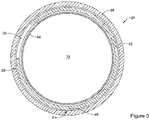
- FIG. 3 shows a cross-sectional view along line 3-3 of FIG. 2 .
- FIG. 3 depicts introducer 24 in an unexpanded configuration. Additionally, it can be appreciated that FIG. 3 represents a cross-section of the expandable member 30 of introducer 24.
- FIG. 3 illustrates a liner 44 (discussed above) extending along the inner surface of the expandable member 30. Further, FIG. 3 illustrates that a portion of ribcage 38 may attached (e.g., tacked, fused, integrated, engaged, etc.) with the tubular wall of outer sheath 36 at attachment location 41. In other words, FIG.
- a portion of outer sheath 36 and a portion of ribcage 38 may be manufactured (e.g., tacked/fused/melted/reflowed) such that they are attached together.
- a portion of ribcage 38 may be attached (e.g., tacked, fused, integrated, etc.) with the tubular wall of outer sheath 36 along the longitudinal axis 35 of introducer 24.
- ribcage 38 may be attached to outer sheath 36 in a series of attachment locations 41 that are aligned with one another along the longitudinal axis 35 of introducer 24.
- this is not intended to be limiting. Rather, it is contemplated that ribcage 38 may be attached to outer sheath 36 in a variety of different locations along the interface of outer sheath 36 and ribcage 38.
- ribcage 38 may include one or more first rib members 40 positioned adjacent to one or more second rib members 42.
- FIG. 3 illustrates spine 45 extending longitudinally along the longitudinal axis of introducer 24.
- the attachment points 41 may be longitudinally aligned along the spine 45 of ribcage 38.
- ribcage 38 is not attached to outer sheath 36. It is further contemplated that any portion of ribcage 38 (including spine 45) may be integral with all or a portion of outer sheath 36.
- FIG. 3 further illustrates first rib member 40 and second rib member 42 extending away from spine 45 in a clockwise direction and counterclockwise direction, respectively.
- both first rib member 40 and second rib member 42 include a curved portion which is positioned along the inner surface of sheath member 36, whereby the curved portion of first rib member 40 extends away from spine 45 in a first direction (e.g., clockwise direction) and the second rib member 42 extends away from the spine 45 in a second direction (e.g., counterclockwise direction).
- An example methodology to construct the introducer 24 may include configuring ribcage 38, outer sheath 36 and liner 44 as shown in FIG. 3 followed by applying heat such that outer sheath 36 member melts (e.g., reflows) around ribcage 38 and/or liner 44.
- liner 44 may be constructed from a material that has a higher melting point than either outer sheath 36 and/or ribcage 38, and therefore, will not melt upon the application of heat sufficient to melt outer sheath 36 and/or ribcage 38 together.
- liner 44 may be constructed from a non-thermoplastic material designed to resist melting while heat is applied to reflow outer sheath 36 and ribcage 38 together.
- arrangement of liner 44, outer sheath 36 and ribcage 38 may include a variety of configurations throughout the manufacturing steps.
- examples contemplated herein may include different positions, alignment, spacing, sizes, dimensions, etc. of ribcage 38, liner 44 and/or sheath 36 relative to one another during the manufacturing process and/or final design.
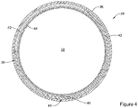
- FIG. 4 is a cross-sectional view (along line 3-3 of FIG. 1 ) of the introducer 24 in an expanded configuration.
- FIG. 4 may depict the expanded configuration of the unexpanded introducer illustrated in FIG. 3 .
- FIG. 3 may depict the introducer 24 prior to a medical device being inserted and/or retracted through the expandable section 30 of the introducer 24, while FIG. 4 may depict the introducer 24 after a medical device has been inserted and/or retracted through the expandable member 30.
- the liner 44 has expanded radially outward. Additionally, it can be appreciated that the liner 44 may continue to expand after it initially contacts the inner surface of the ribcage 38, thereby applying a radially outward force on the first rib member 40 and the second rib member 42 of the ribcage 38.
- the first rib member 40 and the second rib member 42 of the ribcage 38 may expand (e.g., flex) radially outward to accommodate the outward expansion of the liner 44.
- FIG. 4 illustrates the increased distance between the ends of the first rib member 40 and the second rib member 42.
- first rib member 40 and the second rib member 42 of the ribcage 38 may slide along the outer surface of liner 44.
- the sheath 36 may slide along the outer surface of ribcage 38 and/or the liner 44.
- a portion of the sheath member 36 may stretch to accommodate the expanded configuration (e.g., increased diameters) of both the liner 44 and/or the ribcage 38). It is contemplated that as the sheath 36 stretches, its wall thickness may decrease.
- the introducer 24 may contract to a configuration that resembles the unexpanded configuration of the introducer 24 described above. It can be appreciated that after the introducer 24 has been expanded, its configuration may be different from its configuration pre-expansion. For example, after having been expanded, a portion of the liner 44 may extend beyond the first rib member 40 and the second rib member 42 of the ribcage 38. In other words, a portion of the liner 44 may be positioned between the outer surface of the first rib member 40 and/or the second rib member 42 and the inner surface of sheath 36.
- FIG. 5 illustrates an example ribcage 38.
- ribcage 38 may include a first set of rib members 40 positioned adjacent (e.g., interdigitated, interlaced, etc.) a second set of rib members 42.
- FIG. 5 illustrates that both the first set of rib members 40 and the second set of rib members 42 include a curved portion.
- FIG. 5 further illustrates that the first set of rib members 40 and the second set of rib members 42 extend away from a central spine portion 45. Specifically, the first set of rib members 40 extend away from the central spine portion 45 in a clockwise direction while the second set of rib members 42 extend away from the central spine portion 45 in a counterclockwise direction.
- first set of rib members 40 may be described as extending away from a first lateral edge 47 of central spine member 45 and the second set of rib members 42 may be described as extending away from a second lateral edge 49 of central spine member 45. Further, while first set of rib members 40 and second set of rib members 42 extend away from the first lateral edge 47 and second lateral edge 49 of spine member 45, they eventually begin to curve back toward and interdigitate with one another. As shown in FIG. 5 , the curved shape of both first set of rib members 40 and second set of rib members 42 forms a lumen 51. Lumen 51 may include a diameter depicted as "Di" in FIG. 5 .
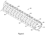
- ribcage 38 may be able to shift (e.g., radially expand) from a non-expanded configuration (such as that shown in FIG. 5 ) to an expandable configuration shown in FIG. 6 .
- the diameter of lumen 51 shown in FIG. 5 (depicted as diameter D 1 ) may increase to define a larger diameter (depicted as "D 2 " in FIG. 6 ).
- FIG. 6 illustrates that as ribcage 38 expands, the first set of rib members 40 and the second set of rib members 42 may radially separate from one another. For example, FIG.
- FIG. 6 depicts the radial separation of the first set of rib members 40 from the second set of rib members 42 via a plurality of double-ended arrows.
- the tips of the double-ended arrows shown in FIG. 6 represent the radial separation between the ends of each of the first set of rib members 40 and the second set of rib members 42, respectively.
- first set of rib members 40 and second set of rib members 42 in FIG. 5 may not interdigitate with one another. Rather, each end of the first set of rib members 40 may radially align with each end of the second set of rib members 42. In other words, the ends of the first set of rib members 40 may not extend past (e.g., may not interdigitate with) the ends of the second set of rib members 42.
- FIGS. 7-10 illustrate an example not claimed method of use of the medical device system 10 and introducer 24.
- the introducer sheath 24 is pre-loaded onto the shaft 12 of the medical device system 10.
- FIG. 7 shows introducer 24 disposed along shaft 12 and positioned between the handle 17 and the implantable medical device 16.
- FIG. 7 shows that in some instances the distal end region 20 of the medical device system 100 may include a tip member 22 which is designed to be advanced through an access site of a patient.
- the dotted line 50 in FIG. 7 represents the access site (e.g., puncture site) into the body.
- FIG. 7 shows that the tip member 22 being inserted through the access site and into the body.
- Tip member 22 may include one or more tapered regions to aid the insertion of the tip 22 into the body.
- FIG. 7 further illustrates that the implantable medical device 16, shaft 12 and the introducer sheath 24 (including expandable portion 30) have not been advanced into the body.
- FIG. 8 illustrates the implantable medical device 16 having been inserted into the body (e.g., a body lumen). Additionally FIG. illustrates that the introducer sheath 24 has been advanced along the shaft 12 to a position in which the distal end region 28 of the shaft is positioned within the body (e.g., a body lumen). As illustrated in FIG. 8 , the expandable portion 30 of the introducer sheath 24 may remain in an unexpanded configuration as the introducer sheath is being inserted in the body. Additionally, FIG. 8 shows that the implantable medical device 16 has not been deployed (e.g., released) from the example medical device delivery system 10.
- the implantable medical device 16 has not been deployed (e.g., released) from the example medical device delivery system 10.
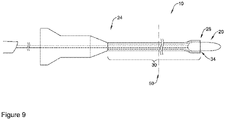
- FIG. 9 illustrates the medical device system 10 being withdrawn from the body after the implantable medical device 16 (not shown in FIG. 9 ) has been deployed at a target site.
- FIG. 9 illustrates that the distal end portion 20 of the medical device system 10 has been withdrawn to a position in which it is contacting the distal end region 28 of the introducer sheath 24.
- the distal end region 28 of the introducer sheath 24 expands radially outward as the medical device system 10 is withdrawn therethrough.
- FIG. 9 illustrates that the distal end region 28 flares (e.g., expands) radially outward to accept the distal end region 20 of the medical device system 10.
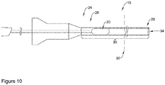
- FIG. 10 illustrates the distal end region 20 of the medical device system 10 being withdrawn from the distal end region 28 to the proximal end region 26 of the introducer sheath 24.
- the medical device may exert a radially outward force from within the lumen 34 upon the wall of the expandable section 30 of the introducer sheath 24.
- the radially outward force may cause the expandable section 30 to expand as the distal end region 20 of the medical device 10 is retracted through the expandable section 30 of the introducer sheath 24.
- FIG. 10 that after the medical device system 10 has been removed from the introducer sheath 24, at least a portion of the introducer sheath 24 may remain inside the body in an expanded configuration. A clinician may then insert additional medical devices through the expanded introducer sheath 24.
- the expansion of the of the introducer sheath 24 from an unexpanded configuration to an expanded configuration may be variable.
- the diameter of the unexpanded introducer sheath 24 may increase to an expanded diameter, after which, it may contract to a diameter that is greater than the diameter of the unexpanded configuration.
- this is not intended to be limiting. It is contemplated that once the unexpanded distal section is expanded, it may remain expanded or it may return to any diameter less than the expanded diameter (including a diameter that is less than the unexpanded diameter).
- introducer 24 may be made from materials such as metals, metal alloys, polymers, ceramics, metal-polymer composites, or other suitable materials, and the like.
- suitable materials may include metallic materials such as stainless steels (e.g. 304v stainless steel or 316L stainless steel), nickel-titanium alloys (e.g., nitinol, such as super elastic or linear elastic nitinol), nickel-chromium alloys, nickel-chromium-iron alloys, cobalt alloys, nickel, titanium, platinum, or alternatively, a polymeric material, such as a high performance polymer, or other suitable materials, and the like.
- stainless steels e.g. 304v stainless steel or 316L stainless steel
- nickel-titanium alloys e.g., nitinol, such as super elastic or linear elastic nitinol
- nickel-chromium alloys nickel-chromium-iron alloys
- cobalt alloys nickel, titanium, platinum, or alternatively
- nitinol was coined by a group of researchers at the United States Naval Ordinance Laboratory (NOL) who were the first to observe the shape memory behavior of this material.
- NOL United States Naval Ordinance Laboratory
- the word nitinol is an acronym including the chemical symbol for nickel (Ni), the chemical symbol for titanium (Ti), and an acronym identifying the Naval Ordinance Laboratory (NOL).
- the introducer 24 (or other introducers and components thereof described herein) may be made from materials such as, for example, a polymeric material, a ceramic, a metal, a metal alloy, a metal-polymer composite, or the like.
- suitable polymers may include polyurethane, a polyether-ester such as ARNITEL ® available from DSM Engineering Plastics, a polyester such as HYTREL ® available from DuPont, a linear low density polyethylene such as REXELL ® , a polyamide such as DURETHAN ® available from Bayer or CRISTAMID ® available from Elf Atochem, an elastomeric polyamide, a block polyamide/ether, a polyether block amide such as PEBA available under the trade name PEBAX ® , silicones, polyethylene, Marlex high-density polyethylene, polyetheretherketone (PEEK), polyimide (PI), and polyetherimide (PEI), a liquid crystal polymer (LCP) alone or blended with other materials.
- a polyether-ester such as ARNITEL ® available from DSM Engineering Plastics
- HYTREL ® available from DuPont
- a linear low density polyethylene such as REXELL ®
- a suitable polymeric material may have a yield strain of at least 20%, at least 30%, at least 40%, at least 50%, or more.
- the sheath, the membrane, and/or the plurality of corrugations may be made from a material having a low coefficient of friction.
- the sheath, the membrane, and/or the plurality of corrugations may be formed from a fluoropolymer, such as polytetrafluoroethylene (PTFE) or fluorinated ethylene propylene (FEP).
- PTFE polytetrafluoroethylene
- FEP fluorinated ethylene propylene
- Portions of introducer 24 may be made of, may be doped with, may include a layer of, or otherwise may include a radiopaque material.
- Radiopaque materials are understood to be materials capable of producing a relatively bright image on a fluoroscopy screen or another imaging technique such as X-ray during a medical procedure. This relatively bright image aids the user of device in determining its location.
- one or more of the elements described above i.e., the sheath, the membrane, the medical device, etc.
- Suitable materials can include, but are not limited to, bismuth subcarbonate, iodine, gold, platinum, palladium, tantalum, tungsten or tungsten alloy, and the like.
- devices and exemplary methods in accordance with the disclosure can be adapted and configured for use in other parts of the anatomy of a patient.
- devices and exemplary methods in accordance with the disclosure can be adapted for use in the digestive or gastrointestinal tract, such as in the mouth, throat, small and large intestine, colon, rectum, and the like.
- devices and exemplary methods can be adapted and configured for use within the respiratory tract, such as in the mouth, nose, throat, bronchial passages, nasal passages, lungs, and the like.
- the devices and exemplary methods described herein with respect to percutaneous deployment may be used in other types of surgical procedures as appropriate.
- the devices may be deployed in a non-percutaneous procedure.
- Devices and exemplary methods in accordance with the disclosure can also be adapted and configured for other uses within the anatomy.
Landscapes
- Health & Medical Sciences (AREA)
- Life Sciences & Earth Sciences (AREA)
- Biomedical Technology (AREA)
- Engineering & Computer Science (AREA)
- Public Health (AREA)
- General Health & Medical Sciences (AREA)
- Heart & Thoracic Surgery (AREA)
- Veterinary Medicine (AREA)
- Animal Behavior & Ethology (AREA)
- Surgery (AREA)
- Cardiology (AREA)
- Molecular Biology (AREA)
- Pathology (AREA)
- Medical Informatics (AREA)
- Nuclear Medicine, Radiotherapy & Molecular Imaging (AREA)
- Oral & Maxillofacial Surgery (AREA)
- Transplantation (AREA)
- Vascular Medicine (AREA)
- Biophysics (AREA)
- Pulmonology (AREA)
- Anesthesiology (AREA)
- Hematology (AREA)
- Prostheses (AREA)
- Media Introduction/Drainage Providing Device (AREA)
Claims (10)
- Système de pose d'implant (10), comprenant :une tige (12) de cathéter ayant une région extrémité distale (20) et une région extrémité proximale (18) ;un implant (16) accouplé à la région extrémité distale (20) de la tige (12) de cathéter ;une poignée (17) accouplée à la région extrémité proximale (18) de la tige (12) de cathéter ; etune gaine d'introducteur (24) disposée le long de la tige (12) de cathéter, la gaine d'introducteur (24) comprenant :une doublure interne (44) comprenant une lumière (34) ;un élément de support extensible (38), l'élément de support (38) comprend une pluralité de nervures (40, 42) s'étendant sur une longueur de l'élément de support (38) ; etune gaine (36) fixée à au moins une partie de l'élément de support (38) ;dans lequel l'élément de support (38) est conçu pour se décaler d'une première position à une position étendue,caractérisé en ce que la gaine d'introducteur (24) est préchargée sur le système de pose d'implant (10) et en ce que la gaine d'introducteur (24) se décale vers la position étendue à mesure que la région extrémité distale (20) de la tige (12) de cathéter est retirée à travers la gaine d'introducteur (24).
- Système de pose d'implant selon la revendication 1, dans lequel la gaine d'introducteur (24) peut coulisser le long de la tige (12) de cathéter.
- Système de pose d'implant selon l'une quelconque des revendications 1 et 2, dans lequel la région extrémité distale (20) est conçue pour perforer une lumière du corps.
- Système de pose d'implant selon l'une quelconque des revendications 1 à 3, dans lequel la gaine d'introducteur (24) n'est pas étendue dans la première position.
- Système de pose d'implant selon l'une quelconque des revendications 1 à 4, dans lequel la pluralité d'éléments nervures (40, 42) s'étend seulement le long d'une partie de la gaine d'introducteur (24).
- Système de pose d'implant selon l'une quelconque des revendications 1 à 5, dans lequel l'élément de support extensible (38) s'étend autour d'au moins une partie de la doublure interne (44).
- Système de pose d'implant selon l'une quelconque des revendications 1 à 6, dans lequel l'élément de support (38) est positionné entre la doublure interne (44) et la gaine (36).
- Système de pose d'implant selon l'une quelconque des revendications 1 à 7, dans lequel la pluralité de nervures (40, 42) est libre de se déplacer par rapport à la doublure (44), à la gaine (36), ou à la fois à la doublure et à la gaine (36).
- Système de pose d'implant selon l'une quelconque des revendications 1 à 8, dans lequel la pluralité de nervures (40, 42) comprend un premier ensemble d'éléments nervures (40) et un second ensemble d'éléments nervures (42), et dans lequel le premier ensemble d'éléments nervures (40) s'interdigite avec le second ensemble d'éléments nervures (42).
- Système de pose d'implant selon l'une quelconque des revendications 1 à 9, dans lequel l'implant est une valve cardiaque implantable.
Priority Applications (1)
| Application Number | Priority Date | Filing Date | Title |
|---|---|---|---|
| EP22181102.9A EP4085853A1 (fr) | 2017-07-31 | 2018-07-31 | Système d'introduction avec capacités d'extension |
Applications Claiming Priority (2)
| Application Number | Priority Date | Filing Date | Title |
|---|---|---|---|
| US201762539293P | 2017-07-31 | 2017-07-31 | |
| PCT/US2018/044500 WO2019027956A1 (fr) | 2017-07-31 | 2018-07-31 | Système d'introduction avec capacités d'extension |
Related Child Applications (1)
| Application Number | Title | Priority Date | Filing Date |
|---|---|---|---|
| EP22181102.9A Division EP4085853A1 (fr) | 2017-07-31 | 2018-07-31 | Système d'introduction avec capacités d'extension |
Publications (2)
| Publication Number | Publication Date |
|---|---|
| EP3661436A1 EP3661436A1 (fr) | 2020-06-10 |
| EP3661436B1 true EP3661436B1 (fr) | 2022-06-29 |
Family
ID=63209686
Family Applications (2)
| Application Number | Title | Priority Date | Filing Date |
|---|---|---|---|
| EP22181102.9A Pending EP4085853A1 (fr) | 2017-07-31 | 2018-07-31 | Système d'introduction avec capacités d'extension |
| EP18755620.4A Active EP3661436B1 (fr) | 2017-07-31 | 2018-07-31 | Système d'introduction avec capacités d'extension |
Family Applications Before (1)
| Application Number | Title | Priority Date | Filing Date |
|---|---|---|---|
| EP22181102.9A Pending EP4085853A1 (fr) | 2017-07-31 | 2018-07-31 | Système d'introduction avec capacités d'extension |
Country Status (4)
| Country | Link |
|---|---|
| US (1) | US20190029825A1 (fr) |
| EP (2) | EP4085853A1 (fr) |
| CN (1) | CN111163719A (fr) |
| WO (1) | WO2019027956A1 (fr) |
Cited By (2)
| Publication number | Priority date | Publication date | Assignee | Title |
|---|---|---|---|---|
| US11617650B2 (en) | 2012-05-30 | 2023-04-04 | Neovasc Tiara Inc. | Methods and apparatus for loading a prosthesis onto a delivery system |
| US11998447B2 (en) | 2020-03-06 | 2024-06-04 | Neovasc Tiara Inc. | Retrievable prosthesis delivery system |
Families Citing this family (38)
| Publication number | Priority date | Publication date | Assignee | Title |
|---|---|---|---|---|
| US9554897B2 (en) | 2011-04-28 | 2017-01-31 | Neovasc Tiara Inc. | Methods and apparatus for engaging a valve prosthesis with tissue |
| US10265086B2 (en) | 2014-06-30 | 2019-04-23 | Neuravi Limited | System for removing a clot from a blood vessel |
| CN113350659A (zh) | 2016-02-24 | 2021-09-07 | 禾木(中国)生物工程有限公司 | 柔性增强的神经血管导管 |
| US10548631B2 (en) | 2016-03-04 | 2020-02-04 | Boston Scientific Scimed Inc. | Introducer with expandable capabilities |
| CN110300557B (zh) * | 2016-12-09 | 2022-06-28 | 波士顿科学国际有限公司 | 具有可扩张性能的导引器 |
| CN110381855B (zh) | 2017-01-06 | 2023-07-04 | 因赛普特有限责任公司 | 用于动脉瘤治疗装置的抗血栓涂层 |
| EP3672530A4 (fr) | 2017-08-25 | 2021-04-14 | Neovasc Tiara Inc. | Prothèse de valvule mitrale transcathéter à déploiement séquentiel |
| WO2019161175A1 (fr) | 2018-02-15 | 2019-08-22 | Boston Scientific Scimed, Inc. | Dispositif d'introduction avec capacités de déploiement |
| US11395665B2 (en) | 2018-05-01 | 2022-07-26 | Incept, Llc | Devices and methods for removing obstructive material, from an intravascular site |
| WO2019212984A1 (fr) | 2018-05-01 | 2019-11-07 | Imperative Care, Inc. | Dispositifs et procédés de retrait de matériau obstructif d'un site intravasculaire |
| US11471582B2 (en) | 2018-07-06 | 2022-10-18 | Incept, Llc | Vacuum transfer tool for extendable catheter |
| WO2020010310A1 (fr) | 2018-07-06 | 2020-01-09 | Imperative Care, Inc. | Cathéter neurovasculaire extensible étanche |
| EP4129382A1 (fr) | 2018-09-10 | 2023-02-08 | Boston Scientific Scimed, Inc. | Introducteur avec capacités de déploiement |
| WO2020093172A1 (fr) | 2018-11-08 | 2020-05-14 | Neovasc Tiara Inc. | Déploiement ventriculaire d'une prothèse de valvule mitrale transcathéter |
| EP4000540B1 (fr) | 2019-03-04 | 2024-02-14 | Neuravi Limited | Cathéter de récupération de caillot actionné |
| US11766539B2 (en) | 2019-03-29 | 2023-09-26 | Incept, Llc | Enhanced flexibility neurovascular catheter |
| CA3135753C (fr) | 2019-04-01 | 2023-10-24 | Neovasc Tiara Inc. | Valve prothetique deployable de maniere controlable |
| AU2020279750B2 (en) | 2019-05-20 | 2023-07-13 | Neovasc Tiara Inc. | Introducer with hemostasis mechanism |
| WO2020257643A1 (fr) | 2019-06-20 | 2020-12-24 | Neovasc Tiara Inc. | Valve mitrale prothétique à profil bas |
| JP2021041169A (ja) | 2019-09-11 | 2021-03-18 | ニューラヴィ・リミテッド | 拡大可能な口腔カテーテル |
| EP4044906A4 (fr) | 2019-10-15 | 2023-05-24 | Imperative Care, Inc. | Systèmes et procédés de détection d'attaque multivariable |
| US11839725B2 (en) | 2019-11-27 | 2023-12-12 | Neuravi Limited | Clot retrieval device with outer sheath and inner catheter |
| US11779364B2 (en) | 2019-11-27 | 2023-10-10 | Neuravi Limited | Actuated expandable mouth thrombectomy catheter |
| US11439799B2 (en) | 2019-12-18 | 2022-09-13 | Imperative Care, Inc. | Split dilator aspiration system |
| CN113365687A (zh) | 2019-12-18 | 2021-09-07 | 因普瑞缇夫护理公司 | 治疗静脉血栓栓塞疾病的方法和系统 |
| US11633272B2 (en) | 2019-12-18 | 2023-04-25 | Imperative Care, Inc. | Manually rotatable thrombus engagement tool |
| EP4069160A1 (fr) * | 2020-01-16 | 2022-10-12 | Edwards Lifesciences Corporation | Systèmes et méthodes de contrôle de fluide |
| US11944327B2 (en) | 2020-03-05 | 2024-04-02 | Neuravi Limited | Expandable mouth aspirating clot retrieval catheter |
| US11633198B2 (en) | 2020-03-05 | 2023-04-25 | Neuravi Limited | Catheter proximal joint |
| EP4117762A4 (fr) | 2020-03-10 | 2024-05-08 | Imperative Care Inc | Cathéter neurovasculaire à flexibilité améliorée |
| US11883043B2 (en) | 2020-03-31 | 2024-01-30 | DePuy Synthes Products, Inc. | Catheter funnel extension |
| US11759217B2 (en) | 2020-04-07 | 2023-09-19 | Neuravi Limited | Catheter tubular support |
| US11207497B1 (en) | 2020-08-11 | 2021-12-28 | Imperative Care, Inc. | Catheter with enhanced tensile strength |
| CA3208121A1 (fr) * | 2021-01-19 | 2022-07-28 | Edwards Lifesciences Corporation | Gaine extensible |
| US11872354B2 (en) * | 2021-02-24 | 2024-01-16 | Neuravi Limited | Flexible catheter shaft frame with seam |
| AU2022287973A1 (en) * | 2021-06-10 | 2023-12-14 | Edwards Lifesciences Corporation | Atraumatic tip for expandable and recoverable sheath |
| US11937839B2 (en) | 2021-09-28 | 2024-03-26 | Neuravi Limited | Catheter with electrically actuated expandable mouth |
| WO2023164027A1 (fr) * | 2022-02-28 | 2023-08-31 | Edwards Lifesciences Corporation | Dilatateur avec élément d'encapsulation pour pointes de gaine |
Citations (2)
| Publication number | Priority date | Publication date | Assignee | Title |
|---|---|---|---|---|
| US20120041371A1 (en) * | 2005-03-30 | 2012-02-16 | Access Scientific, Inc. | Access device with blunting device |
| US20160175128A1 (en) * | 2014-12-23 | 2016-06-23 | Cook Medical Technologies Llc | Introducer with side opening |
Family Cites Families (7)
| Publication number | Priority date | Publication date | Assignee | Title |
|---|---|---|---|---|
| US8623075B2 (en) * | 2010-04-21 | 2014-01-07 | Medtronic, Inc. | Transcatheter prosthetic heart valve delivery system and method with controlled expansion of prosthetic heart valve |
| US10856978B2 (en) * | 2010-05-20 | 2020-12-08 | Jenavalve Technology, Inc. | Catheter system |
| US9907931B2 (en) * | 2012-10-26 | 2018-03-06 | Medtronic, Inc. | Elastic introducer sheath |
| US9801657B2 (en) * | 2014-09-12 | 2017-10-31 | Freudenberg Medical, Llc | Expandable introducer sheath |
| US10327896B2 (en) * | 2015-04-10 | 2019-06-25 | Edwards Lifesciences Corporation | Expandable sheath with elastomeric cross sectional portions |
| US10792471B2 (en) * | 2015-04-10 | 2020-10-06 | Edwards Lifesciences Corporation | Expandable sheath |
| EP3405126A1 (fr) * | 2016-01-21 | 2018-11-28 | Boston Scientific Scimed, Inc. | Dispositifs médicaux et procédés d'utilisation associés |
-
2018
- 2018-07-31 EP EP22181102.9A patent/EP4085853A1/fr active Pending
- 2018-07-31 CN CN201880062073.XA patent/CN111163719A/zh active Pending
- 2018-07-31 US US16/050,062 patent/US20190029825A1/en not_active Abandoned
- 2018-07-31 WO PCT/US2018/044500 patent/WO2019027956A1/fr unknown
- 2018-07-31 EP EP18755620.4A patent/EP3661436B1/fr active Active
Patent Citations (2)
| Publication number | Priority date | Publication date | Assignee | Title |
|---|---|---|---|---|
| US20120041371A1 (en) * | 2005-03-30 | 2012-02-16 | Access Scientific, Inc. | Access device with blunting device |
| US20160175128A1 (en) * | 2014-12-23 | 2016-06-23 | Cook Medical Technologies Llc | Introducer with side opening |
Cited By (2)
| Publication number | Priority date | Publication date | Assignee | Title |
|---|---|---|---|---|
| US11617650B2 (en) | 2012-05-30 | 2023-04-04 | Neovasc Tiara Inc. | Methods and apparatus for loading a prosthesis onto a delivery system |
| US11998447B2 (en) | 2020-03-06 | 2024-06-04 | Neovasc Tiara Inc. | Retrievable prosthesis delivery system |
Also Published As
| Publication number | Publication date |
|---|---|
| EP3661436A1 (fr) | 2020-06-10 |
| EP4085853A1 (fr) | 2022-11-09 |
| US20190029825A1 (en) | 2019-01-31 |
| WO2019027956A1 (fr) | 2019-02-07 |
| CN111163719A (zh) | 2020-05-15 |
Similar Documents
| Publication | Publication Date | Title |
|---|---|---|
| EP3661436B1 (fr) | Système d'introduction avec capacités d'extension | |
| US11931068B2 (en) | Introducer with expandable capabilities | |
| US10980569B2 (en) | Introducer with expandable capabilities | |
| US11076884B2 (en) | Introducer with expandable capabilities | |
| US10966829B2 (en) | Medical device shaft including a liner | |
| US20090319019A1 (en) | Expandable Tip Delivery System For Endoluminal Prosthesis | |
| US20180325548A1 (en) | Introducer with expandable capabilities | |
| EP3908197A1 (fr) | Cathéter d'extension de guidage | |
| US20190083082A1 (en) | Introducer with expandable capabilities | |
| EP3752236B1 (fr) | Dispositif d'introduction avec capacités de déploiement | |
| US20190070001A1 (en) | Medical device with tip member | |
| US20220233313A1 (en) | Medical device including attachable components | |
| US11723767B2 (en) | Medical device including attachable tip member | |
| US20220039813A1 (en) | Devices and methods for treating a stricture along the biliary and/or pancreatic tract | |
| US20230030295A1 (en) | Tyne docking for percutaneous coronary intervention access |
Legal Events
| Date | Code | Title | Description |
|---|---|---|---|
| STAA | Information on the status of an ep patent application or granted ep patent |
Free format text: STATUS: UNKNOWN |
|
| STAA | Information on the status of an ep patent application or granted ep patent |
Free format text: STATUS: THE INTERNATIONAL PUBLICATION HAS BEEN MADE |
|
| PUAI | Public reference made under article 153(3) epc to a published international application that has entered the european phase |
Free format text: ORIGINAL CODE: 0009012 |
|
| STAA | Information on the status of an ep patent application or granted ep patent |
Free format text: STATUS: REQUEST FOR EXAMINATION WAS MADE |
|
| 17P | Request for examination filed |
Effective date: 20200203 |
|
| AK | Designated contracting states |
Kind code of ref document: A1 Designated state(s): AL AT BE BG CH CY CZ DE DK EE ES FI FR GB GR HR HU IE IS IT LI LT LU LV MC MK MT NL NO PL PT RO RS SE SI SK SM TR |
|
| AX | Request for extension of the european patent |
Extension state: BA ME |
|
| DAV | Request for validation of the european patent (deleted) | ||
| DAX | Request for extension of the european patent (deleted) | ||
| STAA | Information on the status of an ep patent application or granted ep patent |
Free format text: STATUS: EXAMINATION IS IN PROGRESS |
|
| 17Q | First examination report despatched |
Effective date: 20210423 |
|
| REG | Reference to a national code |
Ref country code: DE Ref legal event code: R079 Ref document number: 602018037348 Country of ref document: DE Free format text: PREVIOUS MAIN CLASS: A61B0017340000 Ipc: A61M0025060000 |
|
| GRAP | Despatch of communication of intention to grant a patent |
Free format text: ORIGINAL CODE: EPIDOSNIGR1 |
|
| STAA | Information on the status of an ep patent application or granted ep patent |
Free format text: STATUS: GRANT OF PATENT IS INTENDED |
|
| RIC1 | Information provided on ipc code assigned before grant |
Ipc: A61M 25/00 20060101ALN20220203BHEP Ipc: A61B 17/34 20060101ALI20220203BHEP Ipc: A61F 2/24 20060101ALI20220203BHEP Ipc: A61M 25/06 20060101AFI20220203BHEP |
|
| INTG | Intention to grant announced |
Effective date: 20220216 |
|
| GRAS | Grant fee paid |
Free format text: ORIGINAL CODE: EPIDOSNIGR3 |
|
| GRAA | (expected) grant |
Free format text: ORIGINAL CODE: 0009210 |
|
| STAA | Information on the status of an ep patent application or granted ep patent |
Free format text: STATUS: THE PATENT HAS BEEN GRANTED |
|
| AK | Designated contracting states |
Kind code of ref document: B1 Designated state(s): AL AT BE BG CH CY CZ DE DK EE ES FI FR GB GR HR HU IE IS IT LI LT LU LV MC MK MT NL NO PL PT RO RS SE SI SK SM TR |
|
| REG | Reference to a national code |
Ref country code: CH Ref legal event code: EP |
|
| REG | Reference to a national code |
Ref country code: DE Ref legal event code: R096 Ref document number: 602018037348 Country of ref document: DE |
|
| REG | Reference to a national code |
Ref country code: AT Ref legal event code: REF Ref document number: 1500884 Country of ref document: AT Kind code of ref document: T Effective date: 20220715 |
|
| REG | Reference to a national code |
Ref country code: IE Ref legal event code: FG4D |
|
| REG | Reference to a national code |
Ref country code: NL Ref legal event code: FP |
|
| REG | Reference to a national code |
Ref country code: LT Ref legal event code: MG9D |
|
| PG25 | Lapsed in a contracting state [announced via postgrant information from national office to epo] |
Ref country code: SE Free format text: LAPSE BECAUSE OF FAILURE TO SUBMIT A TRANSLATION OF THE DESCRIPTION OR TO PAY THE FEE WITHIN THE PRESCRIBED TIME-LIMIT Effective date: 20220629 Ref country code: NO Free format text: LAPSE BECAUSE OF FAILURE TO SUBMIT A TRANSLATION OF THE DESCRIPTION OR TO PAY THE FEE WITHIN THE PRESCRIBED TIME-LIMIT Effective date: 20220929 Ref country code: LT Free format text: LAPSE BECAUSE OF FAILURE TO SUBMIT A TRANSLATION OF THE DESCRIPTION OR TO PAY THE FEE WITHIN THE PRESCRIBED TIME-LIMIT Effective date: 20220629 Ref country code: HR Free format text: LAPSE BECAUSE OF FAILURE TO SUBMIT A TRANSLATION OF THE DESCRIPTION OR TO PAY THE FEE WITHIN THE PRESCRIBED TIME-LIMIT Effective date: 20220629 Ref country code: GR Free format text: LAPSE BECAUSE OF FAILURE TO SUBMIT A TRANSLATION OF THE DESCRIPTION OR TO PAY THE FEE WITHIN THE PRESCRIBED TIME-LIMIT Effective date: 20220930 Ref country code: FI Free format text: LAPSE BECAUSE OF FAILURE TO SUBMIT A TRANSLATION OF THE DESCRIPTION OR TO PAY THE FEE WITHIN THE PRESCRIBED TIME-LIMIT Effective date: 20220629 Ref country code: BG Free format text: LAPSE BECAUSE OF FAILURE TO SUBMIT A TRANSLATION OF THE DESCRIPTION OR TO PAY THE FEE WITHIN THE PRESCRIBED TIME-LIMIT Effective date: 20220929 |
|
| REG | Reference to a national code |
Ref country code: AT Ref legal event code: MK05 Ref document number: 1500884 Country of ref document: AT Kind code of ref document: T Effective date: 20220629 |
|
| PG25 | Lapsed in a contracting state [announced via postgrant information from national office to epo] |
Ref country code: RS Free format text: LAPSE BECAUSE OF FAILURE TO SUBMIT A TRANSLATION OF THE DESCRIPTION OR TO PAY THE FEE WITHIN THE PRESCRIBED TIME-LIMIT Effective date: 20220629 Ref country code: LV Free format text: LAPSE BECAUSE OF FAILURE TO SUBMIT A TRANSLATION OF THE DESCRIPTION OR TO PAY THE FEE WITHIN THE PRESCRIBED TIME-LIMIT Effective date: 20220629 |
|
| PG25 | Lapsed in a contracting state [announced via postgrant information from national office to epo] |
Ref country code: SM Free format text: LAPSE BECAUSE OF FAILURE TO SUBMIT A TRANSLATION OF THE DESCRIPTION OR TO PAY THE FEE WITHIN THE PRESCRIBED TIME-LIMIT Effective date: 20220629 Ref country code: SK Free format text: LAPSE BECAUSE OF FAILURE TO SUBMIT A TRANSLATION OF THE DESCRIPTION OR TO PAY THE FEE WITHIN THE PRESCRIBED TIME-LIMIT Effective date: 20220629 Ref country code: RO Free format text: LAPSE BECAUSE OF FAILURE TO SUBMIT A TRANSLATION OF THE DESCRIPTION OR TO PAY THE FEE WITHIN THE PRESCRIBED TIME-LIMIT Effective date: 20220629 Ref country code: PT Free format text: LAPSE BECAUSE OF FAILURE TO SUBMIT A TRANSLATION OF THE DESCRIPTION OR TO PAY THE FEE WITHIN THE PRESCRIBED TIME-LIMIT Effective date: 20221031 Ref country code: ES Free format text: LAPSE BECAUSE OF FAILURE TO SUBMIT A TRANSLATION OF THE DESCRIPTION OR TO PAY THE FEE WITHIN THE PRESCRIBED TIME-LIMIT Effective date: 20220629 Ref country code: EE Free format text: LAPSE BECAUSE OF FAILURE TO SUBMIT A TRANSLATION OF THE DESCRIPTION OR TO PAY THE FEE WITHIN THE PRESCRIBED TIME-LIMIT Effective date: 20220629 Ref country code: AT Free format text: LAPSE BECAUSE OF FAILURE TO SUBMIT A TRANSLATION OF THE DESCRIPTION OR TO PAY THE FEE WITHIN THE PRESCRIBED TIME-LIMIT Effective date: 20220629 |
|
| PG25 | Lapsed in a contracting state [announced via postgrant information from national office to epo] |
Ref country code: PL Free format text: LAPSE BECAUSE OF FAILURE TO SUBMIT A TRANSLATION OF THE DESCRIPTION OR TO PAY THE FEE WITHIN THE PRESCRIBED TIME-LIMIT Effective date: 20220629 Ref country code: IS Free format text: LAPSE BECAUSE OF FAILURE TO SUBMIT A TRANSLATION OF THE DESCRIPTION OR TO PAY THE FEE WITHIN THE PRESCRIBED TIME-LIMIT Effective date: 20221029 |
|
| REG | Reference to a national code |
Ref country code: CH Ref legal event code: PL |
|
| REG | Reference to a national code |
Ref country code: BE Ref legal event code: MM Effective date: 20220731 |
|
| REG | Reference to a national code |
Ref country code: DE Ref legal event code: R097 Ref document number: 602018037348 Country of ref document: DE |
|
| PG25 | Lapsed in a contracting state [announced via postgrant information from national office to epo] |
Ref country code: MC Free format text: LAPSE BECAUSE OF FAILURE TO SUBMIT A TRANSLATION OF THE DESCRIPTION OR TO PAY THE FEE WITHIN THE PRESCRIBED TIME-LIMIT Effective date: 20220629 Ref country code: AL Free format text: LAPSE BECAUSE OF FAILURE TO SUBMIT A TRANSLATION OF THE DESCRIPTION OR TO PAY THE FEE WITHIN THE PRESCRIBED TIME-LIMIT Effective date: 20220629 |
|
| PG25 | Lapsed in a contracting state [announced via postgrant information from national office to epo] |
Ref country code: LU Free format text: LAPSE BECAUSE OF NON-PAYMENT OF DUE FEES Effective date: 20220731 Ref country code: LI Free format text: LAPSE BECAUSE OF NON-PAYMENT OF DUE FEES Effective date: 20220731 Ref country code: DK Free format text: LAPSE BECAUSE OF FAILURE TO SUBMIT A TRANSLATION OF THE DESCRIPTION OR TO PAY THE FEE WITHIN THE PRESCRIBED TIME-LIMIT Effective date: 20220629 Ref country code: CZ Free format text: LAPSE BECAUSE OF FAILURE TO SUBMIT A TRANSLATION OF THE DESCRIPTION OR TO PAY THE FEE WITHIN THE PRESCRIBED TIME-LIMIT Effective date: 20220629 Ref country code: CH Free format text: LAPSE BECAUSE OF NON-PAYMENT OF DUE FEES Effective date: 20220731 |
|
| PLBE | No opposition filed within time limit |
Free format text: ORIGINAL CODE: 0009261 |
|
| STAA | Information on the status of an ep patent application or granted ep patent |
Free format text: STATUS: NO OPPOSITION FILED WITHIN TIME LIMIT |
|
| PG25 | Lapsed in a contracting state [announced via postgrant information from national office to epo] |
Ref country code: BE Free format text: LAPSE BECAUSE OF NON-PAYMENT OF DUE FEES Effective date: 20220731 |
|
| 26N | No opposition filed |
Effective date: 20230330 |
|
| PGFP | Annual fee paid to national office [announced via postgrant information from national office to epo] |
Ref country code: NL Payment date: 20230623 Year of fee payment: 6 Ref country code: IE Payment date: 20230622 Year of fee payment: 6 Ref country code: FR Payment date: 20230621 Year of fee payment: 6 |
|
| PG25 | Lapsed in a contracting state [announced via postgrant information from national office to epo] |
Ref country code: SI Free format text: LAPSE BECAUSE OF FAILURE TO SUBMIT A TRANSLATION OF THE DESCRIPTION OR TO PAY THE FEE WITHIN THE PRESCRIBED TIME-LIMIT Effective date: 20220629 |
|
| PGFP | Annual fee paid to national office [announced via postgrant information from national office to epo] |
Ref country code: GB Payment date: 20230620 Year of fee payment: 6 |
|
| PGFP | Annual fee paid to national office [announced via postgrant information from national office to epo] |
Ref country code: DE Payment date: 20230620 Year of fee payment: 6 |
|
| PG25 | Lapsed in a contracting state [announced via postgrant information from national office to epo] |
Ref country code: IT Free format text: LAPSE BECAUSE OF FAILURE TO SUBMIT A TRANSLATION OF THE DESCRIPTION OR TO PAY THE FEE WITHIN THE PRESCRIBED TIME-LIMIT Effective date: 20220629 |
|
| PG25 | Lapsed in a contracting state [announced via postgrant information from national office to epo] |
Ref country code: MK Free format text: LAPSE BECAUSE OF FAILURE TO SUBMIT A TRANSLATION OF THE DESCRIPTION OR TO PAY THE FEE WITHIN THE PRESCRIBED TIME-LIMIT Effective date: 20220629 Ref country code: CY Free format text: LAPSE BECAUSE OF FAILURE TO SUBMIT A TRANSLATION OF THE DESCRIPTION OR TO PAY THE FEE WITHIN THE PRESCRIBED TIME-LIMIT Effective date: 20220629 |