EP3661417B1 - System for determining forces at the feet - Google Patents
System for determining forces at the feet Download PDFInfo
- Publication number
- EP3661417B1 EP3661417B1 EP18832978.3A EP18832978A EP3661417B1 EP 3661417 B1 EP3661417 B1 EP 3661417B1 EP 18832978 A EP18832978 A EP 18832978A EP 3661417 B1 EP3661417 B1 EP 3661417B1
- Authority
- EP
- European Patent Office
- Prior art keywords
- force
- sensors
- type
- force sensors
- electronic circuit
- Prior art date
- Legal status (The legal status is an assumption and is not a legal conclusion. Google has not performed a legal analysis and makes no representation as to the accuracy of the status listed.)
- Active
Links
- 238000012545 processing Methods 0.000 claims description 15
- 238000005259 measurement Methods 0.000 claims description 11
- 230000004044 response Effects 0.000 claims description 8
- 230000005021 gait Effects 0.000 claims description 4
- 230000001133 acceleration Effects 0.000 claims description 3
- 238000006243 chemical reaction Methods 0.000 claims description 3
- 238000000034 method Methods 0.000 claims description 3
- 230000008569 process Effects 0.000 claims description 2
- 210000002683 foot Anatomy 0.000 description 10
- 230000005540 biological transmission Effects 0.000 description 8
- 230000035479 physiological effects, processes and functions Effects 0.000 description 4
- 239000011159 matrix material Substances 0.000 description 3
- 238000004458 analytical method Methods 0.000 description 2
- 238000009530 blood pressure measurement Methods 0.000 description 2
- 238000004891 communication Methods 0.000 description 2
- 229910001416 lithium ion Inorganic materials 0.000 description 2
- 230000001360 synchronised effect Effects 0.000 description 2
- 230000000007 visual effect Effects 0.000 description 2
- OKTJSMMVPCPJKN-UHFFFAOYSA-N Carbon Chemical compound [C] OKTJSMMVPCPJKN-UHFFFAOYSA-N 0.000 description 1
- 238000010521 absorption reaction Methods 0.000 description 1
- 238000013459 approach Methods 0.000 description 1
- 238000003491 array Methods 0.000 description 1
- 230000008901 benefit Effects 0.000 description 1
- 229910052799 carbon Inorganic materials 0.000 description 1
- 239000002131 composite material Substances 0.000 description 1
- 230000003750 conditioning effect Effects 0.000 description 1
- 230000001419 dependent effect Effects 0.000 description 1
- 238000010017 direct printing Methods 0.000 description 1
- 238000005516 engineering process Methods 0.000 description 1
- 239000000835 fiber Substances 0.000 description 1
- 210000004744 fore-foot Anatomy 0.000 description 1
- 230000006870 function Effects 0.000 description 1
- 230000006872 improvement Effects 0.000 description 1
- 239000003562 lightweight material Substances 0.000 description 1
- 230000035939 shock Effects 0.000 description 1
- 239000007787 solid Substances 0.000 description 1
- 238000012800 visualization Methods 0.000 description 1
Images


Classifications
-
- A—HUMAN NECESSITIES
- A61—MEDICAL OR VETERINARY SCIENCE; HYGIENE
- A61B—DIAGNOSIS; SURGERY; IDENTIFICATION
- A61B5/00—Measuring for diagnostic purposes; Identification of persons
- A61B5/103—Detecting, measuring or recording devices for testing the shape, pattern, colour, size or movement of the body or parts thereof, for diagnostic purposes
- A61B5/1036—Measuring load distribution, e.g. podologic studies
- A61B5/1038—Measuring plantar pressure during gait
-
- A—HUMAN NECESSITIES
- A43—FOOTWEAR
- A43B—CHARACTERISTIC FEATURES OF FOOTWEAR; PARTS OF FOOTWEAR
- A43B17/00—Insoles for insertion, e.g. footbeds or inlays, for attachment to the shoe after the upper has been joined
-
- A—HUMAN NECESSITIES
- A43—FOOTWEAR
- A43B—CHARACTERISTIC FEATURES OF FOOTWEAR; PARTS OF FOOTWEAR
- A43B3/00—Footwear characterised by the shape or the use
- A43B3/34—Footwear characterised by the shape or the use with electrical or electronic arrangements
-
- A—HUMAN NECESSITIES
- A61—MEDICAL OR VETERINARY SCIENCE; HYGIENE
- A61B—DIAGNOSIS; SURGERY; IDENTIFICATION
- A61B5/00—Measuring for diagnostic purposes; Identification of persons
- A61B5/103—Detecting, measuring or recording devices for testing the shape, pattern, colour, size or movement of the body or parts thereof, for diagnostic purposes
- A61B5/11—Measuring movement of the entire body or parts thereof, e.g. head or hand tremor, mobility of a limb
- A61B5/1112—Global tracking of patients, e.g. by using GPS
-
- A—HUMAN NECESSITIES
- A61—MEDICAL OR VETERINARY SCIENCE; HYGIENE
- A61B—DIAGNOSIS; SURGERY; IDENTIFICATION
- A61B5/00—Measuring for diagnostic purposes; Identification of persons
- A61B5/103—Detecting, measuring or recording devices for testing the shape, pattern, colour, size or movement of the body or parts thereof, for diagnostic purposes
- A61B5/11—Measuring movement of the entire body or parts thereof, e.g. head or hand tremor, mobility of a limb
- A61B5/112—Gait analysis
-
- A—HUMAN NECESSITIES
- A61—MEDICAL OR VETERINARY SCIENCE; HYGIENE
- A61B—DIAGNOSIS; SURGERY; IDENTIFICATION
- A61B5/00—Measuring for diagnostic purposes; Identification of persons
- A61B5/68—Arrangements of detecting, measuring or recording means, e.g. sensors, in relation to patient
- A61B5/6801—Arrangements of detecting, measuring or recording means, e.g. sensors, in relation to patient specially adapted to be attached to or worn on the body surface
- A61B5/6802—Sensor mounted on worn items
- A61B5/6804—Garments; Clothes
- A61B5/6807—Footwear
-
- A—HUMAN NECESSITIES
- A61—MEDICAL OR VETERINARY SCIENCE; HYGIENE
- A61B—DIAGNOSIS; SURGERY; IDENTIFICATION
- A61B2562/00—Details of sensors; Constructional details of sensor housings or probes; Accessories for sensors
- A61B2562/02—Details of sensors specially adapted for in-vivo measurements
- A61B2562/0247—Pressure sensors
Definitions
- Measurement of plantar pressure can be used for improving performance in sports and for diagnostic and rehabilitation or other purposes in healthcare.
- In-shoe force or pressure analysis can be used for medical purposes to help with rehabilitation, diagnose problems related to balance, sway, gait, or other foot functions.
- In-shoe force and pressure analysis can also be used to improve performance in sports, for example for track, football or basketball.
- Force-time graphs can provide valuable information on physiology or performance. Frequently such data are used and assessed in comparison to a threshold or to an ideal profile, or to the user's historical data, in order to draw useful conclusions. For example, such conclusions may relate to proper positioning, strength, or synchronicity of an athlete.
- Systems that are used for medical diagnostic purposes can be considered as part of the investment in infrastructure that a clinic makes for example, and patients would just use these systems every time they visit their clinician.
- users may have to each have their own pair of sensing shoes. For example, a football team may need to have more than 30 shoes for different players. For many applications therefore, low cost is an additional requirement to reliable data and fast response.
- EP0846441 (B1) discloses sensors in arrays formed as a matrix addressable by rows and columns, each point in time interrogating the output of each row and column in a switchable manner.
- the problem with this arrangement is that a matrix of resistive type or strain type sensors is not very accurate and there is always a small time lag of the measurement of one physical point on the insole in relation to another physical point in the insole.
- ES2120860 (B1 ) discloses a matrix arrangement consisting of 2048 piezoresistive elements. Although such approach makes it possible to find the pressure at any point of the footprint, there is a significant cost associated to this.
- reliable pressure measurement requires a rigid layer upon which sensors rest.
- US9005140B2 discloses an arrangement where the bottom layer of an insole is rigid. Such arrangement has the disadvantage that it is not suitable where good performance requires a flexible insole, as is the case with many sports related applications.
- US2014222173 discloses a system whereby a plurality of force sensors are used where there is at least one sensor in each of the phalange portion of the foot, a forefoot portion, and a heel portion. Each of the signals of the force sensors is compared to templates or other information related to that sensor.
- individual pressure points are used, conclusions may be more difficult to draw as the system is critically dependent on the physiology of the user and each time needs to be recalibrated for the physiology of the user.
- Signal processing is also more complex the greater the number of sensors used, and failure of a single sensor may render the system useless.
- WO2006100331A2 discloses pressure surface that is divided into independent, adjacent zones and having numerous sensors. Each of the zones is equipped with an output terminal and a powered flexible printed circuit collects the terminals and conducts or transmits same wirelessly to an intelligent system which interprets the signals.
- the arrangement of sensors in zones is meaningful but the system can be very expensive if high accuracy sensors are used.
- the objective of this invention is to provide an in-shoe sensing system that can be comfortably used for long periods and which can provide high reliability in measurements at a relatively low cost. The reliability of measurement should be safeguarded even if some sensor fails.
- a further objective of this invention is to allow comparisons among profiles of many users by enabling simplified signal processing that is not tied to the specific physiology of each individual user. This for example can be important for sports teams in trials or for a coach who needs to guide athletes or plan his game.
- Yet a further objective of this invention is to enable a natural and comfortable feeling by being able to utilize an insole that can bend naturally.
- the invention comprises of a system for sensing in-sole force in a footwear characterized by the use of a plurality of force sensors arranged in zones wherein the plurality force sensors comprise sensors of type A and sensors of type B.
- Type A and Type B sensors measure the same parameter; type A may be high range of force and type B may be low range of force. Alternatively, type A may be fast response rate, and type B slow response rate.
- sensors are in contact with one or more rigid surfaces.
- the combination of type A and type B sensors arranged in zones enables good and reliable signals to be obtained without high cost.
- a flexible electronic circuit connects said force sensors, and a signal is transmitted to a processing unit.
- the measuring system is integral with the sole (1) of the shoe and comprises a lower layer (2), an upper layer (3), a plurality of sensors (4), a flexible electronic circuit (5) that connects said sensors (4), and a powering and handling unit (6).
- the lower layer is integral or in contact with the sole of the footwear and the upper layer is in contact with the foot, characterized in that the plurality of sensors comprise sensors of type A and Type B.
- Type A and Type B sensors measure the same parameter; type A may be high range of force and type B may be low force range. Alternatively, type A may be fast response rate, and type B slow response rate.
- the upper layer includes a number of rigid surfaces (12).
- the electronic circuit is connected to powering and handling unit (6) and to a processing unit. In a preferred embodiment, the processing unit is remote and data transmission is done wirelessly.
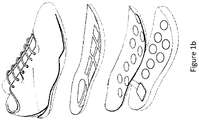
- Figure 1b shows an alternative embodiment wherein the lower layer (22) further comprises depressions (16) where sensors (4) at least partially fit in.
- sensors are force or pressure sensors.
- Force sensors may measure inferiorsuperior (vertical), anterior-posterior (back-front), and medial-lateral (side-to-side) forces experienced on the plantar surface of the foot. Inferiorsuperior or vertical ground reaction force is often the most significant force that is used to assess performance and medical condition.
- the power supply (61) is in the form of a small battery, preferably a coin-type Li-Ion battery.
- the power supply may integrate a wireless charging capability (67) to recharge said battery.
- Memory (62) is preferably flash memory, e-PROM, e2-PROM, or other solid state memory.
- Transmission (64) is in a preferred embodiment a wireless transmitter, the form of which may vary depending of the application and the demands for transmission range.
- the power and handling unit may also integrate an integrated accelerometer and gyroscope component (65) to measure foot orientation, gait speed and acceleration.
- a GPS unit (66) may also be included in said power and handling unit to record geographic location of measurement and augment the accelerometer and gyroscope measurement to accurately position the footwear.
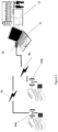
- the processing of the data is done by a remote computer (8).
- Figure 2 shows an embodiment where data is transmitted wirelessly, by transmission units (64a, 64b) in each shoe, to a remote computer (8).
- This remote computer may be for example a laptop or desktop computer, a smart phone or tablet, or another wearable or handheld device.
- Each measuring system at each shoe generates a signal (9a, 9b) which is then transmitted to a computer receiver (10).
- the two signals (9a, 9b) are synchronized and then processed in order to provide visualizations (11) or other meaningful information after signal processing.
- Triggering for recording can be done for example by a wireless signal that triggers both measurement systems at each shoe to start recording at the same time. Triggering may also be done when an internal clock at each measuring system in each shoe reaches a set time. The two clocks, one at each shoe, are synchronized in advance.
- Processing comprises comparisons of time series data. Such comparisons can for example indicate the degree of improvement that an athlete achieves over time.
- the upper layer (3, 31) that is in contact with the foot comprises several rigid plates (12) which are organized in zones (13). These rigid plates are made of lightweight material such as carbon fibre composite. A certain degree of flexing is possible and in fact desirable for these rigid plates (6). Different rigid plates (12) may have a different rigidity or a different degree of flexing depending on the position or the application.
- Figure 3b shows an example of layer comprising rigid plates of different rigidity (12a, 12b, 12c). Rigidity is necessary to ensure that force is effectively transferred to the different sensors (4) that are in contact with a rigid plate (12). A balance of high, medium, or low rigidity provides comfort and natural movement while satisfying the objective of transferring force or pressure to the sensors.
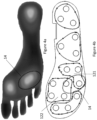
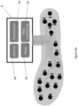
- FIG 4a shows a typical pressure region (14) of a foot and figure 4b shows the same region (14) matched onto the upper layer of a measuring system.
- the pressure region spans two rigid plates (121,122).
- a single rigid plate generally is in contact both with sensor Type A (4A) and sensor Type B (4B).
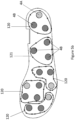
- Figure 5a illustrates an arrangement in one preferred embodiment where each of the shown rigid plates (12) is in contact with two types of sensors, both Type A (4A) and Type B (4B).
- FIG. 5b shows an arrangement in an alternative embodiment where a zone (121) is in contact with sensors of one type only, type B (4B), whereas other zones (120) are in contact with both sensor type A and sensor type B.
- sensor type B may represent a sensor of slower response rate, and hence being of a lower cost.
- a zone includes both type A and type B sensors, where type A may be a sensor covering one pressure range and type B may be a sensor covering another pressure range, enables high overall accuracy and reliability at much lower cost.
- Figure 6 shows an example of force or pressure ranges that sensors may cover.
- sensors that maintain high accuracy over a long range tend to be more expensive than sensors that maintain accuracy over a smaller range.
- Type A and Type B sensors may represent sensors operating at a different range of force or pressure measurement. In this way, higher resolution is achieved for a lower cost by combining the signals from two sensors each operating at a narrow range, since sensors operating at a wider range are generally more expensive than sensors operating at a narrow range for the same resolution.
- errors in sensors are less in the region of 10-50% of full scale. For example, a sensor that measures zero to 100 Kg, when measuring 5Kg force would have a much greater error than a sensor that has an operating range zero to 50Kg force and measures 5Kg force.
- Different types of sensors may include different sensing specifications, for example different operating ranges, different sensing area, different full scale (FS) accuracy and different linearity, drift and repeatability.
- the lower the cost of a sensor generally the lower the accuracy, linearity or repeatability.
- signal processing can be simplified by taking a value of the average of the values from each individual sensor for those sensors for whom the actual force value is within their operating range.
- Sensors are connected to a flexible electronic circuit which is in turn connected to the powering and handing unit (6).
- Figure 7 shows an example of such flexible electronic circuit. It is possible that all components on such circuit are printed and flexible.
- a flexible connector (51) leads to the powering and handing unit (6).
- Figure 8a shows the powering and handing unit (6) which comprises power supply (61), memory (62), data conditioning (63), and transmission (64).
- the power supply (61) is in the form of a small battery, preferably a coin-type Li-Ion battery.
- Memory (62) is preferably flash memory, e-PROM, e2-PROM, or other solidstate memory. It is also possible that there is no memory, and data is transmitted directly as generated. Transmission (64) is, in a preferred embodiment, a wireless transmitter. The specific transmitted technology depends on the application and the demands for transmission range. In another embodiment, there is no data transmission. Data is stored in memory and downloaded when the shoe is in proximity to a computer by connecting a communication device to a connection port that accesses memory. Such port could be for example a USB port.
- Figure 8b shows the power and handling unit with embedded accelerometer and gyroscope (65), GPS (66) and wireless charging capability (67).
- An integrated accelerometer and gyroscope component (65) is used to measure foot orientation, gait speed and acceleration.
- a GPS unit (66) is used to record geographic location of measurement and augment the accelerometer and gyroscope measurement to accurately position the footwear.
- Figures 9a and 9b illustrate a preferred embodiment where the powering and handing unit (6) is secured in a cavity (15) within the sole of the shoe. This has the advantage that the powering and handling unit is completely concealed. On the other hand, this may have negative impact regarding the performance of the shoes such as rebound and shock absorption and may also have a negative impact on the range of the transmitted.
- Figure 10 shows an alternative embodiment wherein the power and handing unit may be secure on the external upper surface of the shoe, and the flexible electronic circuit may be in I communication with the powering and handing unit (6) via a long flexible connector (51).
- pressure and force may be used interchangeably as both parameters fundamentally relate to the same physical condition of the foot and pressure is force distributed on the area of a sensor.
Description
- Measurement of plantar pressure can be used for improving performance in sports and for diagnostic and rehabilitation or other purposes in healthcare. In-shoe force or pressure analysis can be used for medical purposes to help with rehabilitation, diagnose problems related to balance, sway, gait, or other foot functions. In-shoe force and pressure analysis can also be used to improve performance in sports, for example for track, football or basketball.
- There are several solutions to the market that measure in-sole pressure and translate that into a visual pressure map or into force-time graphs. Force-time graphs can provide valuable information on physiology or performance. Frequently such data are used and assessed in comparison to a threshold or to an ideal profile, or to the user's historical data, in order to draw useful conclusions. For example, such conclusions may relate to proper positioning, strength, or synchronicity of an athlete.
- Systems that are used for medical diagnostic purposes, can be considered as part of the investment in infrastructure that a clinic makes for example, and patients would just use these systems every time they visit their clinician. In other cases, for example in sports applications, users may have to each have their own pair of sensing shoes. For example, a football team may need to have more than 30 shoes for different players. For many applications therefore, low cost is an additional requirement to reliable data and fast response.
- There are several known systems that use in-shoe pressure or force related measurements and which provide a profile of pressure distribution or force-time signals. The use of multiple sensors is well known in the art, see for example
US2014326085 ,WO2006100331 ,KR101530225 KR20110124964 -
EP0846441 (B1) discloses sensors in arrays formed as a matrix addressable by rows and columns, each point in time interrogating the output of each row and column in a switchable manner. The problem with this arrangement is that a matrix of resistive type or strain type sensors is not very accurate and there is always a small time lag of the measurement of one physical point on the insole in relation to another physical point in the insole. - In a similar manner
ES2120860 (B1 - In many implementations, reliable pressure measurement requires a rigid layer upon which sensors rest.
- For example,
US9005140B2 - Most systems utilizing individual sensors, and process that data from each individual sensor. For example,
US2014222173 (A1) discloses a system whereby a plurality of force sensors are used where there is at least one sensor in each of the phalange portion of the foot, a forefoot portion, and a heel portion. Each of the signals of the force sensors is compared to templates or other information related to that sensor. When individual pressure points are used, conclusions may be more difficult to draw as the system is critically dependent on the physiology of the user and each time needs to be recalibrated for the physiology of the user. Signal processing is also more complex the greater the number of sensors used, and failure of a single sensor may render the system useless. - Different special arrangements of sensors are known in the art and in many cases sensors are known to be organized in zones. For example,
WO2006100331A2 discloses pressure surface that is divided into independent, adjacent zones and having numerous sensors. Each of the zones is equipped with an output terminal and a powered flexible printed circuit collects the terminals and conducts or transmits same wirelessly to an intelligent system which interprets the signals. The arrangement of sensors in zones is meaningful but the system can be very expensive if high accuracy sensors are used. - The objective of this invention is to provide an in-shoe sensing system that can be comfortably used for long periods and which can provide high reliability in measurements at a relatively low cost. The reliability of measurement should be safeguarded even if some sensor fails. A further objective of this invention is to allow comparisons among profiles of many users by enabling simplified signal processing that is not tied to the specific physiology of each individual user. This for example can be important for sports teams in trials or for a coach who needs to guide athletes or plan his game. Yet a further objective of this invention, is to enable a natural and comfortable feeling by being able to utilize an insole that can bend naturally.
- The invention comprises of a system for sensing in-sole force in a footwear characterized by the use of a plurality of force sensors arranged in zones wherein the plurality force sensors comprise sensors of type A and sensors of type B. Type A and Type B sensors measure the same parameter; type A may be high range of force and type B may be low range of force. Alternatively, type A may be fast response rate, and type B slow response rate. Within each zone of the footwear, sensors are in contact with one or more rigid surfaces. The combination of type A and type B sensors arranged in zones enables good and reliable signals to be obtained without high cost. A flexible electronic circuit connects said force sensors, and a signal is transmitted to a processing unit.
-
-
FIG. 1a illustrates an example of the layers of a sole of a shoe in a preferred embodiment wherein the system is integral to the sole of the shoe -
FIG. 1b illustrates an embodiment wherein the lower layer further comprises depressions where sensors at least partially fit in. -
FIG. 2 illustrates an example of an overall system including devices in two shoes communicating with a processing unit -
FIG. 3a illustrates an example of an embodiment with zones and rigid plates -
FIG. 3b illustrates an example of an embodiment with zones and rigid plates of different degree of rigidity -
FIGs. 4a and 4b illustrate an example of an alternative embodiment where rigid plates do not coincide with physiological pressure zones of the foot -
FIG. 5a illustrates an example of an embodiment with sensors positioned at the heel zone showing type A and type B sensors -
FIG. 5b illustrates an example of an embodiment with sensors Type A and Type B arranged at different zones -
FIG. 6 illustrates and example of the different operating ranges of pressure or force sensors -
FIG. 7 schematically illustrates and example of sensors mounted onto flexible electronic layer -
FIG. 8a schematically illustrates the modules of the power and handling unit -
FIG. 8b schematically illustrates the modules of the power and handling unit with embedded accelerometer, gyroscope and wireless charging capability. -
FIGS 9a and 9b illustrate the positioning of the power and handling unit into a depression in the sole of the shoe -
FIG 10 illustrates an alternative positioning of the power and handling unit at a position outside the sole of the shoe - With reference to
Figure 1a , the measuring system is integral with the sole (1) of the shoe and comprises a lower layer (2), an upper layer (3), a plurality of sensors (4), a flexible electronic circuit (5) that connects said sensors (4), and a powering and handling unit (6). The lower layer is integral or in contact with the sole of the footwear and the upper layer is in contact with the foot, characterized in that the plurality of sensors comprise sensors of type A and Type B. Type A and Type B sensors measure the same parameter; type A may be high range of force and type B may be low force range. Alternatively, type A may be fast response rate, and type B slow response rate. The upper layer includes a number of rigid surfaces (12). The electronic circuit is connected to powering and handling unit (6) and to a processing unit. In a preferred embodiment, the processing unit is remote and data transmission is done wirelessly. -
Figure 1b shows an alternative embodiment wherein the lower layer (22) further comprises depressions (16) where sensors (4) at least partially fit in. - In a preferred embodiment, sensors are force or pressure sensors. Force sensors may measure inferiorsuperior (vertical), anterior-posterior (back-front), and medial-lateral (side-to-side) forces experienced on the plantar surface of the foot. Inferiorsuperior or vertical ground reaction force is often the most significant force that is used to assess performance and medical condition.
- The power supply (61) is in the form of a small battery, preferably a coin-type Li-Ion battery. The power supply may integrate a wireless charging capability (67) to recharge said battery. Memory (62) is preferably flash memory, e-PROM, e2-PROM, or other solid state memory. Transmission (64) is in a preferred embodiment a wireless transmitter, the form of which may vary depending of the application and the demands for transmission range. The power and handling unit may also integrate an integrated accelerometer and gyroscope component (65) to measure foot orientation, gait speed and acceleration. A GPS unit (66) may also be included in said power and handling unit to record geographic location of measurement and augment the accelerometer and gyroscope measurement to accurately position the footwear.
- In a preferred embodiment, the processing of the data is done by a remote computer (8).
Figure 2 shows an embodiment where data is transmitted wirelessly, by transmission units (64a, 64b) in each shoe, to a remote computer (8). This remote computer may be for example a laptop or desktop computer, a smart phone or tablet, or another wearable or handheld device. Each measuring system at each shoe, generates a signal (9a, 9b) which is then transmitted to a computer receiver (10). The two signals (9a, 9b) are synchronized and then processed in order to provide visualizations (11) or other meaningful information after signal processing. - Triggering for recording can be done for example by a wireless signal that triggers both measurement systems at each shoe to start recording at the same time. Triggering may also be done when an internal clock at each measuring system in each shoe reaches a set time. The two clocks, one at each shoe, are synchronized in advance.
- Data is collected as time series, and in one preferred embodiment processing comprises comparisons of time series data. Such comparisons can for example indicate the degree of improvement that an athlete achieves over time.
- As illustrated by
figure 3a , the upper layer (3, 31) that is in contact with the foot comprises several rigid plates (12) which are organized in zones (13). These rigid plates are made of lightweight material such as carbon fibre composite. A certain degree of flexing is possible and in fact desirable for these rigid plates (6). Different rigid plates (12) may have a different rigidity or a different degree of flexing depending on the position or the application.Figure 3b shows an example of layer comprising rigid plates of different rigidity (12a, 12b, 12c). Rigidity is necessary to ensure that force is effectively transferred to the different sensors (4) that are in contact with a rigid plate (12). A balance of high, medium, or low rigidity provides comfort and natural movement while satisfying the objective of transferring force or pressure to the sensors. - Rigid plates may not always match the pressure regions of the food applied to the shoe.
Figure 4a shows a typical pressure region (14) of a foot andfigure 4b shows the same region (14) matched onto the upper layer of a measuring system. In this example, the pressure region spans two rigid plates (121,122). - A single rigid plate generally is in contact both with sensor Type A (4A) and sensor Type B (4B).
Figure 5a illustrates an arrangement in one preferred embodiment where each of the shown rigid plates (12) is in contact with two types of sensors, both Type A (4A) and Type B (4B). By having both type A and type B sensors in contact with the same rigid plate, the signal can be effectively averaged out, while fluctuations are higher frequencies can be captured by the sensor with the faster response rate. - A single rigid plate may not be in contact with both sensor type A (4A) and sensor type B (4B).
Figure 5b shows an arrangement in an alternative embodiment where a zone (121) is in contact with sensors of one type only, type B (4B), whereas other zones (120) are in contact with both sensor type A and sensor type B. For example, sensor type B may represent a sensor of slower response rate, and hence being of a lower cost. - The arrangement whereby a zone includes both type A and type B sensors, where type A may be a sensor covering one pressure range and type B may be a sensor covering another pressure range, enables high overall accuracy and reliability at much lower cost.
Figure 6 shows an example of force or pressure ranges that sensors may cover. Generally, sensors that maintain high accuracy over a long range tend to be more expensive than sensors that maintain accuracy over a smaller range. Type A and Type B sensors may represent sensors operating at a different range of force or pressure measurement. In this way, higher resolution is achieved for a lower cost by combining the signals from two sensors each operating at a narrow range, since sensors operating at a wider range are generally more expensive than sensors operating at a narrow range for the same resolution. - Typically errors in sensors are less in the region of 10-50% of full scale. For example, a sensor that measures zero to 100 Kg, when measuring 5Kg force would have a much greater error than a sensor that has an operating range zero to 50Kg force and measures 5Kg force.
- Different types of sensors may include different sensing specifications, for example different operating ranges, different sensing area, different full scale (FS) accuracy and different linearity, drift and repeatability. The lower the cost of a sensor generally the lower the accuracy, linearity or repeatability.
- The use of different types of sensors also allows for the use of a higher performance sensor, such as higher accuracy sensor, to be used to calibrate a lower performance sensor thus achieving good performance at much lower cost.
- In a configuration where several sensors (4) are in contact with a rigid plate (12) signal processing can be simplified by taking a value of the average of the values from each individual sensor for those sensors for whom the actual force value is within their operating range. By using simple averages comparisons and visual examination of force or force maps is made a lot easier for the medical doctor or for a sports coach for example.
- In a configuration where several sensors (4) are in contact with rigid plates (12) it is also possible to compensate for failure of a single sensor enabling the system to continue to be used even if one sensor fails.
- In a configuration where several sensors (4) are in contact with rigid plates (12) in zones (13), by taking the sum of individual sensor values in each zone, the total force value for that zone is calculated. Force values for each zone are summed to provide the total vertical ground reaction force value for said footwear.
- Sensors are connected to a flexible electronic circuit which is in turn connected to the powering and handing unit (6).
Figure 7 shows an example of such flexible electronic circuit. It is possible that all components on such circuit are printed and flexible. A flexible connector (51) leads to the powering and handing unit (6). Several sensors (4) connected to the flexible electronic circuit (5). In another embodiment, sensors are integral to the flexible electronic circuit, and are produced by direct printing techniques. -
Figure 8a shows the powering and handing unit (6) which comprises power supply (61), memory (62), data conditioning (63), and transmission (64). The power supply (61) is in the form of a small battery, preferably a coin-type Li-Ion battery. Memory (62) is preferably flash memory, e-PROM, e2-PROM, or other solidstate memory. It is also possible that there is no memory, and data is transmitted directly as generated. Transmission (64) is, in a preferred embodiment, a wireless transmitter. The specific transmitted technology depends on the application and the demands for transmission range. In another embodiment, there is no data transmission. Data is stored in memory and downloaded when the shoe is in proximity to a computer by connecting a communication device to a connection port that accesses memory. Such port could be for example a USB port. -
Figure 8b shows the power and handling unit with embedded accelerometer and gyroscope (65), GPS (66) and wireless charging capability (67). An integrated accelerometer and gyroscope component (65) is used to measure foot orientation, gait speed and acceleration. A GPS unit (66) is used to record geographic location of measurement and augment the accelerometer and gyroscope measurement to accurately position the footwear. -
Figures 9a and 9b illustrate a preferred embodiment where the powering and handing unit (6) is secured in a cavity (15) within the sole of the shoe. This has the advantage that the powering and handling unit is completely concealed. On the other hand, this may have negative impact regarding the performance of the shoes such as rebound and shock absorption and may also have a negative impact on the range of the transmitted. -
Figure 10 shows an alternative embodiment wherein the power and handing unit may be secure on the external upper surface of the shoe, and the flexible electronic circuit may be in I communication with the powering and handing unit (6) via a long flexible connector (51). - In this description and in the claims of this invention pressure and force may be used interchangeably as both parameters fundamentally relate to the same physical condition of the foot and pressure is force distributed on the area of a sensor.
Claims (15)
- Apparatus for sensing in-sole force in footwear comprising:
a lower layer, an upper layer, a plurality of force sensors arranged in zones, a flexible electronic circuit that connects said force sensors, and a power and handling unit connected to the electronic circuit, said power and handling unit receiving raw signals from said sensors wherein the lower layer is integral or in contact with the sole of the footwear and the upper layer is in contact with the foot, characterized in that said force sensors comprise at least two different types of force sensor, type A and type B, wherein type A and type B force sensors differ in the following ways: type A has a higher range of force than type B, type A has a greater accuracy than type B, or type A has a faster response rate than type B. - The apparatus according to claim 1, wherein the upper layer comprises regions of rigid material and regions of flexible material and wherein each region of rigid material is placed above at least part of each zone of force sensors.
- The apparatus according to claim 2, wherein each zone of force sensors is in contact with one or more regions of rigid material of the upper layer.
- The apparatus according to any preceding claim, wherein said force sensors are disposed at essentially the same depth with respect to the surface of said upper layer distal from the foot.
- The apparatus according to any preceding claim, wherein the flexible electronic circuit and the force sensors are integrally connected and form an intermediate layer between said upper layer and said lower layer.
- The apparatus according to any preceding claim, wherein the lower layer further comprises depressions where sensors at least partially fit and/or regions of higher rigidity and regions of lower rigidity.
- The apparatus according to any preceding claim, wherein sensors measure force in vertical or traverse or longitudinal direction or vertical ground reaction force.
- The apparatus according to any preceding claim, wherein an accelerometer, gyroscope and GPS are included in said power and handling unit and wherein the accelerometer and gyroscope measure foot orientation, gait speed and acceleration.
- The apparatus according to any preceding claim, wherein the flexible electronic circuit comprises a memory module adapted such that data may be downloaded from the memory module for processing externally.
- The apparatus according to any of the preceding claims, wherein power is provided by a rechargeable battery, said power and handling unit integrating a wireless charging capability to recharge said battery.
- A system for assessing in-sole force in footwear, comprising apparatus as claimed in any of claims 1 to 10 and a processing unit adapted to receive and process signals from the apparatus.
- The system according to claim 11, wherein the flexible electronic circuit comprises a wireless transmitter and wherein the processing unit is connected to the flexible electronic circuit wirelessly.
- The system according to claim 11 or claim 12, wherein force measurements from force sensors within each zone are summed or averaged to provide a total or an average force value for that zone.
- The system according to any of claims 10 to 13 wherein force sensors of one force range are used to calibrate force sensors of another, different, force range.
- The system according to any of claims 10 to 14, wherein data from the force sensors is collected as time series, and wherein processing by the processing unit comprises comparisons of time series data.
Applications Claiming Priority (2)
| Application Number | Priority Date | Filing Date | Title |
|---|---|---|---|
| GB1712482.7A GB2565124B (en) | 2017-08-03 | 2017-08-03 | System for determining forces at the feet |
| PCT/EP2018/071073 WO2019025572A2 (en) | 2017-08-03 | 2018-08-02 | System for determining forces at the feet |
Publications (2)
| Publication Number | Publication Date |
|---|---|
| EP3661417A2 EP3661417A2 (en) | 2020-06-10 |
| EP3661417B1 true EP3661417B1 (en) | 2023-02-15 |
Family
ID=59894981
Family Applications (1)
| Application Number | Title | Priority Date | Filing Date |
|---|---|---|---|
| EP18832978.3A Active EP3661417B1 (en) | 2017-08-03 | 2018-08-02 | System for determining forces at the feet |
Country Status (9)
| Country | Link |
|---|---|
| US (1) | US11771341B2 (en) |
| EP (1) | EP3661417B1 (en) |
| AU (1) | AU2018309358A1 (en) |
| CA (1) | CA3071877A1 (en) |
| ES (1) | ES2944582T3 (en) |
| GB (1) | GB2565124B (en) |
| PL (1) | PL3661417T3 (en) |
| SG (1) | SG11202000929TA (en) |
| WO (1) | WO2019025572A2 (en) |
Families Citing this family (1)
| Publication number | Priority date | Publication date | Assignee | Title |
|---|---|---|---|---|
| JP2022187868A (en) * | 2021-06-08 | 2022-12-20 | 本田技研工業株式会社 | force detector |
Citations (1)
| Publication number | Priority date | Publication date | Assignee | Title |
|---|---|---|---|---|
| KR101530225B1 (en) * | 2014-04-02 | 2015-06-22 | 경희대학교 산학협력단 | Smart shoes system with hybrid pressure sensor using nanofiber web |
Family Cites Families (27)
| Publication number | Priority date | Publication date | Assignee | Title |
|---|---|---|---|---|
| ES2120860B1 (en) | 1995-05-31 | 2000-10-16 | Univ Zaragoza | ELECTRONIC PEDOMETER. |
| IT1289231B1 (en) | 1996-12-04 | 1998-09-29 | Ist Superiore Sanita | EQUIPMENT FOR TELEMETRY OF FOOT-GROUND INTERACTION FORCES IN A WALKING SUBJECT. |
| WO2006100331A2 (en) | 2005-03-23 | 2006-09-28 | Chasco Perez De Arenaza Juan C | Intelligent zonal pressure surface |
| US7673528B2 (en) * | 2005-05-12 | 2010-03-09 | Euisik Yoon | Flexible modular sensor systems |
| US7426873B1 (en) * | 2006-05-04 | 2008-09-23 | Sandia Corporation | Micro electro-mechanical system (MEMS) pressure sensor for footwear |
| WO2009059134A1 (en) | 2007-11-02 | 2009-05-07 | The Research Foundation Of State University Of New York | Weight monitoring apparatus, weight monitoring system, and related methods thereof |
| US8384551B2 (en) * | 2008-05-28 | 2013-02-26 | MedHab, LLC | Sensor device and method for monitoring physical stresses placed on a user |
| CN102143695A (en) * | 2008-06-13 | 2011-08-03 | 耐克国际有限公司 | Footwear having sensor system |
| US8639455B2 (en) * | 2009-02-09 | 2014-01-28 | Alterg, Inc. | Foot pad device and method of obtaining weight data |
| US20110054359A1 (en) * | 2009-02-20 | 2011-03-03 | The Regents of the University of Colorado , a body corporate | Footwear-based body weight monitor and postural allocation, physical activity classification, and energy expenditure calculator |
| CN101828794B (en) | 2009-12-15 | 2012-02-29 | 东华大学 | Dynamic sole pressure test insole with multilayer sensing core structure |
| KR101191800B1 (en) * | 2010-05-12 | 2012-10-16 | 이진욱 | Shoe insole for walk diagnosis |
| PT105191A (en) * | 2010-07-08 | 2012-01-09 | Fiorima Fabricacao De Peugas S A | ITEM FOR INTEGRATED BIOMETRIC MONITORING |
| KR20130080486A (en) | 2011-11-28 | 2013-07-15 | 김광순 | Pine needle shochu for food. Carrot shochu. How to make cucumber shochu |
| KR101283434B1 (en) * | 2011-11-29 | 2013-07-08 | 이진욱 | Shoe insole sensor for walk diagnosis shoe insole flexible board in contact with the same, and shoe insole for walk diagnosis |
| US20150351665A1 (en) * | 2013-01-24 | 2015-12-10 | MedHab, LLC | Method for measuring power generated during running |
| US11006690B2 (en) | 2013-02-01 | 2021-05-18 | Nike, Inc. | System and method for analyzing athletic activity |
| US10034622B1 (en) * | 2014-10-15 | 2018-07-31 | Fadi A. Mahmoud | In-shoe foot monitoring utilizing an insert |
| CN105768356A (en) * | 2014-12-18 | 2016-07-20 | 西安发威电子科技有限公司 | Intelligent insole with walking posture correction function |
| CN204351176U (en) * | 2015-01-13 | 2015-05-27 | 南通市第三人民医院 | A kind of shoe-pad detecting balance |
| US10222283B2 (en) | 2015-04-08 | 2019-03-05 | Smart Skin Technologies Inc. | Systems and methods of providing automated feedback to a user using a shoe insole assembly |
| WO2017007518A1 (en) | 2015-07-07 | 2017-01-12 | Obma Padraic R | Noninvasive medical monitoring device, system and method |
| CN105380342A (en) * | 2015-10-14 | 2016-03-09 | 上海交通大学 | Intelligent insole system based on capacitive pressure sensors |
| WO2017146350A1 (en) * | 2016-02-22 | 2017-08-31 | 솔티드벤처 주식회사 | Shoe |
| CN205909833U (en) * | 2016-08-01 | 2017-01-25 | 珠海安润普科技有限公司 | Meter step shoe -pad device |
| CN106307772A (en) * | 2016-08-16 | 2017-01-11 | 赵矗 | Intelligent navigation shoes |
| CN106667494B (en) * | 2017-02-23 | 2019-06-28 | 佛山市量脑科技有限公司 | A kind of insole of athletic posture monitoring |
-
2017
- 2017-08-03 GB GB1712482.7A patent/GB2565124B/en active Active
-
2018
- 2018-08-02 PL PL18832978.3T patent/PL3661417T3/en unknown
- 2018-08-02 WO PCT/EP2018/071073 patent/WO2019025572A2/en unknown
- 2018-08-02 EP EP18832978.3A patent/EP3661417B1/en active Active
- 2018-08-02 CA CA3071877A patent/CA3071877A1/en active Pending
- 2018-08-02 US US16/636,179 patent/US11771341B2/en active Active
- 2018-08-02 AU AU2018309358A patent/AU2018309358A1/en active Pending
- 2018-08-02 SG SG11202000929TA patent/SG11202000929TA/en unknown
- 2018-08-02 ES ES18832978T patent/ES2944582T3/en active Active
Patent Citations (1)
| Publication number | Priority date | Publication date | Assignee | Title |
|---|---|---|---|---|
| KR101530225B1 (en) * | 2014-04-02 | 2015-06-22 | 경희대학교 산학협력단 | Smart shoes system with hybrid pressure sensor using nanofiber web |
Also Published As
| Publication number | Publication date |
|---|---|
| GB201712482D0 (en) | 2017-09-20 |
| WO2019025572A3 (en) | 2019-04-25 |
| CA3071877A1 (en) | 2019-02-07 |
| EP3661417A2 (en) | 2020-06-10 |
| WO2019025572A2 (en) | 2019-02-07 |
| PL3661417T3 (en) | 2023-07-10 |
| AU2018309358A1 (en) | 2020-03-19 |
| GB2565124A (en) | 2019-02-06 |
| GB2565124B (en) | 2021-05-05 |
| SG11202000929TA (en) | 2020-02-27 |
| US11771341B2 (en) | 2023-10-03 |
| US20200367788A1 (en) | 2020-11-26 |
| ES2944582T3 (en) | 2023-06-22 |
Similar Documents
| Publication | Publication Date | Title |
|---|---|---|
| US20190254568A1 (en) | Foot-mounted sensor systems for tracking body movement | |
| US10966638B2 (en) | Miniaturized electronic unit for integration in any sole | |
| US20160331322A1 (en) | Apparatuses, devices, and methods for measuring fluid pressure variation in an insole | |
| US8744783B2 (en) | System and method for measuring power generated during legged locomotion | |
| CN107224026B (en) | Shoe with sensor system | |
| EP2750601B1 (en) | Device for monitoring balance and a method for manufacturing thereof | |
| US10222283B2 (en) | Systems and methods of providing automated feedback to a user using a shoe insole assembly | |
| US20210145318A1 (en) | System for detecting a gait disorder of a user and associated methods | |
| KR20180081844A (en) | System and method for analyzing athletic activity | |
| WO2016116071A1 (en) | Insole with integrated nano-pedometer, step detection and counting method using said insole, and shoe equipped with the fixed or removable insole | |
| JPH05161724A (en) | Insole collecting kinesiologic information | |
| KR20170120047A (en) | An inner sole for a shoe | |
| Morris et al. | A compact wearable sensor package for clinical gait monitoring | |
| US20220408872A1 (en) | Insole with embedded sensing system | |
| EP3661417B1 (en) | System for determining forces at the feet | |
| US11432613B2 (en) | Load cell module inserted in shoes and weight management service system using the same | |
| Muzaffar et al. | Piezoresistive sensor array design for shoe-integrated continuous body weight and gait measurement | |
| US20200297241A1 (en) | Wearable computing devices for acquiring athletic movement data, and systems and methods relating thereto | |
| US10524531B2 (en) | Inner sole for a shoe | |
| US20210245007A1 (en) | System for analyzing a pedalling technique of a cyclist and associated methods | |
| TWI821815B (en) | Insole with embedded sensing system | |
| Leemets et al. | Development of a smart insole system for gait and performance monitoring | |
| TWI830517B (en) | Foot sensor and analysis device | |
| CN113347899B (en) | Load sensing device for an article of footwear | |
| US20200245937A1 (en) | Systems and methods to determine center of pressure |
Legal Events
| Date | Code | Title | Description |
|---|---|---|---|
| STAA | Information on the status of an ep patent application or granted ep patent |
Free format text: STATUS: UNKNOWN |
|
| STAA | Information on the status of an ep patent application or granted ep patent |
Free format text: STATUS: THE INTERNATIONAL PUBLICATION HAS BEEN MADE |
|
| PUAI | Public reference made under article 153(3) epc to a published international application that has entered the european phase |
Free format text: ORIGINAL CODE: 0009012 |
|
| STAA | Information on the status of an ep patent application or granted ep patent |
Free format text: STATUS: REQUEST FOR EXAMINATION WAS MADE |
|
| 17P | Request for examination filed |
Effective date: 20200303 |
|
| AK | Designated contracting states |
Kind code of ref document: A2 Designated state(s): AL AT BE BG CH CY CZ DE DK EE ES FI FR GB GR HR HU IE IS IT LI LT LU LV MC MK MT NL NO PL PT RO RS SE SI SK SM TR |
|
| AX | Request for extension of the european patent |
Extension state: BA ME |
|
| DAV | Request for validation of the european patent (deleted) | ||
| DAX | Request for extension of the european patent (deleted) | ||
| GRAP | Despatch of communication of intention to grant a patent |
Free format text: ORIGINAL CODE: EPIDOSNIGR1 |
|
| STAA | Information on the status of an ep patent application or granted ep patent |
Free format text: STATUS: GRANT OF PATENT IS INTENDED |
|
| INTG | Intention to grant announced |
Effective date: 20220902 |
|
| GRAS | Grant fee paid |
Free format text: ORIGINAL CODE: EPIDOSNIGR3 |
|
| GRAA | (expected) grant |
Free format text: ORIGINAL CODE: 0009210 |
|
| STAA | Information on the status of an ep patent application or granted ep patent |
Free format text: STATUS: THE PATENT HAS BEEN GRANTED |
|
| AK | Designated contracting states |
Kind code of ref document: B1 Designated state(s): AL AT BE BG CH CY CZ DE DK EE ES FI FR GB GR HR HU IE IS IT LI LT LU LV MC MK MT NL NO PL PT RO RS SE SI SK SM TR |
|
| REG | Reference to a national code |
Ref country code: CH Ref legal event code: EP Ref country code: GB Ref legal event code: FG4D |
|
| REG | Reference to a national code |
Ref country code: DE Ref legal event code: R096 Ref document number: 602018046232 Country of ref document: DE |
|
| REG | Reference to a national code |
Ref country code: AT Ref legal event code: REF Ref document number: 1547822 Country of ref document: AT Kind code of ref document: T Effective date: 20230315 Ref country code: IE Ref legal event code: FG4D |
|
| REG | Reference to a national code |
Ref country code: LT Ref legal event code: MG9D |
|
| REG | Reference to a national code |
Ref country code: NL Ref legal event code: MP Effective date: 20230215 |
|
| REG | Reference to a national code |
Ref country code: ES Ref legal event code: FG2A Ref document number: 2944582 Country of ref document: ES Kind code of ref document: T3 Effective date: 20230622 |
|
| REG | Reference to a national code |
Ref country code: AT Ref legal event code: MK05 Ref document number: 1547822 Country of ref document: AT Kind code of ref document: T Effective date: 20230215 |
|
| PG25 | Lapsed in a contracting state [announced via postgrant information from national office to epo] |
Ref country code: RS Free format text: LAPSE BECAUSE OF FAILURE TO SUBMIT A TRANSLATION OF THE DESCRIPTION OR TO PAY THE FEE WITHIN THE PRESCRIBED TIME-LIMIT Effective date: 20230215 Ref country code: PT Free format text: LAPSE BECAUSE OF FAILURE TO SUBMIT A TRANSLATION OF THE DESCRIPTION OR TO PAY THE FEE WITHIN THE PRESCRIBED TIME-LIMIT Effective date: 20230615 Ref country code: NO Free format text: LAPSE BECAUSE OF FAILURE TO SUBMIT A TRANSLATION OF THE DESCRIPTION OR TO PAY THE FEE WITHIN THE PRESCRIBED TIME-LIMIT Effective date: 20230515 Ref country code: NL Free format text: LAPSE BECAUSE OF FAILURE TO SUBMIT A TRANSLATION OF THE DESCRIPTION OR TO PAY THE FEE WITHIN THE PRESCRIBED TIME-LIMIT Effective date: 20230215 Ref country code: LV Free format text: LAPSE BECAUSE OF FAILURE TO SUBMIT A TRANSLATION OF THE DESCRIPTION OR TO PAY THE FEE WITHIN THE PRESCRIBED TIME-LIMIT Effective date: 20230215 Ref country code: LT Free format text: LAPSE BECAUSE OF FAILURE TO SUBMIT A TRANSLATION OF THE DESCRIPTION OR TO PAY THE FEE WITHIN THE PRESCRIBED TIME-LIMIT Effective date: 20230215 Ref country code: HR Free format text: LAPSE BECAUSE OF FAILURE TO SUBMIT A TRANSLATION OF THE DESCRIPTION OR TO PAY THE FEE WITHIN THE PRESCRIBED TIME-LIMIT Effective date: 20230215 Ref country code: AT Free format text: LAPSE BECAUSE OF FAILURE TO SUBMIT A TRANSLATION OF THE DESCRIPTION OR TO PAY THE FEE WITHIN THE PRESCRIBED TIME-LIMIT Effective date: 20230215 |
|
| PG25 | Lapsed in a contracting state [announced via postgrant information from national office to epo] |
Ref country code: SE Free format text: LAPSE BECAUSE OF FAILURE TO SUBMIT A TRANSLATION OF THE DESCRIPTION OR TO PAY THE FEE WITHIN THE PRESCRIBED TIME-LIMIT Effective date: 20230215 Ref country code: IS Free format text: LAPSE BECAUSE OF FAILURE TO SUBMIT A TRANSLATION OF THE DESCRIPTION OR TO PAY THE FEE WITHIN THE PRESCRIBED TIME-LIMIT Effective date: 20230615 Ref country code: GR Free format text: LAPSE BECAUSE OF FAILURE TO SUBMIT A TRANSLATION OF THE DESCRIPTION OR TO PAY THE FEE WITHIN THE PRESCRIBED TIME-LIMIT Effective date: 20230516 Ref country code: FI Free format text: LAPSE BECAUSE OF FAILURE TO SUBMIT A TRANSLATION OF THE DESCRIPTION OR TO PAY THE FEE WITHIN THE PRESCRIBED TIME-LIMIT Effective date: 20230215 |
|
| PG25 | Lapsed in a contracting state [announced via postgrant information from national office to epo] |
Ref country code: SM Free format text: LAPSE BECAUSE OF FAILURE TO SUBMIT A TRANSLATION OF THE DESCRIPTION OR TO PAY THE FEE WITHIN THE PRESCRIBED TIME-LIMIT Effective date: 20230215 Ref country code: RO Free format text: LAPSE BECAUSE OF FAILURE TO SUBMIT A TRANSLATION OF THE DESCRIPTION OR TO PAY THE FEE WITHIN THE PRESCRIBED TIME-LIMIT Effective date: 20230215 Ref country code: EE Free format text: LAPSE BECAUSE OF FAILURE TO SUBMIT A TRANSLATION OF THE DESCRIPTION OR TO PAY THE FEE WITHIN THE PRESCRIBED TIME-LIMIT Effective date: 20230215 Ref country code: DK Free format text: LAPSE BECAUSE OF FAILURE TO SUBMIT A TRANSLATION OF THE DESCRIPTION OR TO PAY THE FEE WITHIN THE PRESCRIBED TIME-LIMIT Effective date: 20230215 Ref country code: CZ Free format text: LAPSE BECAUSE OF FAILURE TO SUBMIT A TRANSLATION OF THE DESCRIPTION OR TO PAY THE FEE WITHIN THE PRESCRIBED TIME-LIMIT Effective date: 20230215 |
|
| PGFP | Annual fee paid to national office [announced via postgrant information from national office to epo] |
Ref country code: IT Payment date: 20230811 Year of fee payment: 6 Ref country code: GB Payment date: 20230829 Year of fee payment: 6 Ref country code: ES Payment date: 20230906 Year of fee payment: 6 Ref country code: CH Payment date: 20230902 Year of fee payment: 6 |
|
| REG | Reference to a national code |
Ref country code: DE Ref legal event code: R097 Ref document number: 602018046232 Country of ref document: DE |
|
| PG25 | Lapsed in a contracting state [announced via postgrant information from national office to epo] |
Ref country code: SK Free format text: LAPSE BECAUSE OF FAILURE TO SUBMIT A TRANSLATION OF THE DESCRIPTION OR TO PAY THE FEE WITHIN THE PRESCRIBED TIME-LIMIT Effective date: 20230215 |
|
| PGFP | Annual fee paid to national office [announced via postgrant information from national office to epo] |
Ref country code: PL Payment date: 20230731 Year of fee payment: 6 Ref country code: FR Payment date: 20230816 Year of fee payment: 6 Ref country code: DE Payment date: 20230816 Year of fee payment: 6 |
|
| PLBE | No opposition filed within time limit |
Free format text: ORIGINAL CODE: 0009261 |
|
| STAA | Information on the status of an ep patent application or granted ep patent |
Free format text: STATUS: NO OPPOSITION FILED WITHIN TIME LIMIT |
|
| 26N | No opposition filed |
Effective date: 20231116 |
|
| PG25 | Lapsed in a contracting state [announced via postgrant information from national office to epo] |
Ref country code: SI Free format text: LAPSE BECAUSE OF FAILURE TO SUBMIT A TRANSLATION OF THE DESCRIPTION OR TO PAY THE FEE WITHIN THE PRESCRIBED TIME-LIMIT Effective date: 20230215 |
|
| PG25 | Lapsed in a contracting state [announced via postgrant information from national office to epo] |
Ref country code: MC Free format text: LAPSE BECAUSE OF FAILURE TO SUBMIT A TRANSLATION OF THE DESCRIPTION OR TO PAY THE FEE WITHIN THE PRESCRIBED TIME-LIMIT Effective date: 20230215 |
|
| PG25 | Lapsed in a contracting state [announced via postgrant information from national office to epo] |
Ref country code: MC Free format text: LAPSE BECAUSE OF FAILURE TO SUBMIT A TRANSLATION OF THE DESCRIPTION OR TO PAY THE FEE WITHIN THE PRESCRIBED TIME-LIMIT Effective date: 20230215 |