EP3661386B1 - Koppelbarer koffer - Google Patents
Koppelbarer koffer Download PDFInfo
- Publication number
- EP3661386B1 EP3661386B1 EP18840731.6A EP18840731A EP3661386B1 EP 3661386 B1 EP3661386 B1 EP 3661386B1 EP 18840731 A EP18840731 A EP 18840731A EP 3661386 B1 EP3661386 B1 EP 3661386B1
- Authority
- EP
- European Patent Office
- Prior art keywords
- suitcase
- connecting portion
- housing
- wheels
- pair
- Prior art date
- Legal status (The legal status is an assumption and is not a legal conclusion. Google has not performed a legal analysis and makes no representation as to the accuracy of the status listed.)
- Active
Links
Images


Classifications
-
- A—HUMAN NECESSITIES
- A45—HAND OR TRAVELLING ARTICLES
- A45C—PURSES; LUGGAGE; HAND CARRIED BAGS
- A45C7/00—Collapsible or extensible purses, luggage, bags or the like
- A45C7/0018—Rigid or semi-rigid luggage
- A45C7/0045—Rigid or semi-rigid luggage comprising a plurality of separable elements which can be used independently of one another
-
- A—HUMAN NECESSITIES
- A45—HAND OR TRAVELLING ARTICLES
- A45C—PURSES; LUGGAGE; HAND CARRIED BAGS
- A45C5/00—Rigid or semi-rigid luggage
- A45C5/14—Rigid or semi-rigid luggage with built-in rolling means
-
- A—HUMAN NECESSITIES
- A45—HAND OR TRAVELLING ARTICLES
- A45C—PURSES; LUGGAGE; HAND CARRIED BAGS
- A45C13/00—Details; Accessories
- A45C13/10—Arrangement of fasteners
- A45C13/1069—Arrangement of fasteners magnetic
-
- A—HUMAN NECESSITIES
- A45—HAND OR TRAVELLING ARTICLES
- A45C—PURSES; LUGGAGE; HAND CARRIED BAGS
- A45C13/00—Details; Accessories
- A45C13/26—Special adaptations of handles
- A45C13/262—Special adaptations of handles for wheeled luggage
-
- A—HUMAN NECESSITIES
- A45—HAND OR TRAVELLING ARTICLES
- A45C—PURSES; LUGGAGE; HAND CARRIED BAGS
- A45C13/00—Details; Accessories
- A45C13/26—Special adaptations of handles
- A45C13/262—Special adaptations of handles for wheeled luggage
- A45C2013/265—Special adaptations of handles for wheeled luggage the handle being adjustable in rotation to a towing element
-
- A—HUMAN NECESSITIES
- A45—HAND OR TRAVELLING ARTICLES
- A45C—PURSES; LUGGAGE; HAND CARRIED BAGS
- A45C13/00—Details; Accessories
- A45C13/26—Special adaptations of handles
- A45C13/262—Special adaptations of handles for wheeled luggage
- A45C2013/267—Special adaptations of handles for wheeled luggage the handle being slidable, extractable and lockable in one or more positions
Definitions
- the present invention relates to a connectable suitcase, and in particular a suitcase connectable to other suitcases.
- Items of luggage such as suitcases are generally transported by either lifting, pushing or pulling the suitcase on a set of wheels or stacking multiple suitcases on a luggage trolley.
- the items are handled as individual units. This makes it difficult to transport two suitcases or more in an environment in which no luggage trolley is available. If a luggage trolley is available, such as in an airport environment, it is often necessary to leave the items of luggage to one side in order to find a trolley.
- the trolley is typically coin operated and it can be difficult to lift and balance multiple luggage items on the trolley for transportation. Doing so can require some physical effort and can result in a user straining his or her back. Using a trolley to transport multiple items of luggage can therefore be inconvenient, costly and potentially dangerous, particularly for a single user.
- WO 2015/196238 discloses a suitcase connectable to another suitcase, the suitcase including a first connecting portion disposed on a front surface of the suitcase, a second connecting portion disposed on a rear surface of the suitcase, the first connecting portion being operatively associated with the second connecting portion to connect at least two suitcases front to rear, a front pair of wheels mounted along a first axis, and a rear pair of wheels mounted along a second axis parallel to the first axis, wherein the connection portions are magnetic and attract to lock together.
- An advantage of the above unit is that multiple suitcases can be quickly and easily locked together for transportation as a single unit.
- the wheel configuration enables the front wheels of a rear suitcase to nest between the rear wheels of a forward suitcase when two or more suitcases are connected together. This allows for smooth movement of the suitcase along the ground.
- the suitcases can therefore be connected together and transported without the need for lifting or the use of a trolley.
- the suitcase has an upper surface and a retractable handle mechanism.
- the retractable handle mechanism includes a handle having a pair of telescopic arms and a gripping portion connecting the pair of telescopic arms. More preferably, the gripping portion spans a lateral dimension of the suitcase.
- the telescopic arms include a pivotable hinge at a base thereof for pivotal movement of the retractable handle.
- the retractable handle mechanism is tiltable away from the suitcase.
- the first connection portion of the magnetic connector is installed in the front surface of the unit such that the front plate lies on the front surface of the unit and the end wall lies flush with the front surface in the retracted position thereof.
- the endcap of the first connection portion includes a second connection portion engagement portion and the housing of the second connection portion includes a first connection portion engagement portion for engaging the second part engagement portion of the first part.
- the second part engagement portion of the first part is a male component and the first part engagement portion is a female component.
- the second part of the magnetic connector is installed in the rear surface of the unit such that the female engagement portion protrudes therefrom.
- the second part engagement portion of the first part comprises a peripheral flange of the end wall.
- the first part engagement portion of the second part comprises at least one resilient member. More preferably, the first part engagement portion comprises a plurality of the resilient members spaced from one another around a portion of a sidewall of the housing, the plurality of resilient members together subtending an angle of no more than about 270 degrees.
- the endcap further includes a housing engagement member that extends away from the endcap.
- the housing of the first part has a sidewall with an aperture therein for receiving the housing engagement member of the endcap.
- a distal end of the housing engagement member is arranged to abut the magnet inside the housing of the first part.
- the distal end of the housing engagement member comprises a cam surface, the cam surface terminating in a rebate at a distance away from the distal end so as to form a lug. More preferably, the lug is engageable in the aperture of the sidewall of the housing.
- the first part includes a face plate having a central aperture therein, the face plate being arranged to fit over the housing sidewall in abutment with the peripheral flange of the end wall.
- the housing of the second part includes a sidewall and the magnet is arranged within the sidewall.
- the housing further includes an endcap arranged over the housing to retain the magnet inside the housing.
- the resilient biasing means is a helical spring. More preferably, the helical spring is made of spring steel.
- the housing and endcap of the first part and the housing and endcap of the second part are made of plastic, more preferably nylon.
- a modular unit system comprising a plurality of units in accordance with the first aspect.
- the plurality of units comprises at least a first unit and a second unit and the position of the first part of the two-part connector on the front surface of the first unit and the position of the second part of the two-part connector on the rear surface of the second connector lie on an axis that passes through each of the first and second unit when the units are placed adjacent one another.
- the front surface of the first unit includes two of the first parts spaced from one another and the rear surface of the second unit includes two of the second parts spaced from one another
- correspondingly spaced first parts and second parts lie along respective first and second axes that are laterally spaced from one another and which pass through each of the first and second units when the units placed adjacent one another.
- a method of locking together a first unit and a second unit of a modular unit system comprising the steps of: placing the first unit adjacent the second unit such that the front surface of the first unit is adjacent the rear surface of the second unit, and the first part of one magnetic connector is adjacent a second part of a magnetic connector, so as to cause the resilient biasing means of the first part to contract under the magnetic force of the magnet of the second part, thereby placing the first part in an extended position relative to the second part whereby the male engagement portion of the first part locks into the female engagement part of the second part, thereby locking the units together.
- a magnetic connector for connecting together a first unit and a second unit of a modular unit system, comprising a first part including a housing having an end wall at a proximal end thereof, at least one magnet arranged inside the housing, an endcap attached to the housing at a distal end thereof and a resilient biasing means arranged over the housing between the end wall and the endcap, the magnetic connector further including a second part having a housing and at least one magnet arranged inside the housing, whereby the resilient biasing means is adapted in use to bias the housing and endcap of the first part in a first retracted position relative to the second part and to contract under a magnetic force emitted by the second part to cause the housing and endcap of the first part to move to a second extended position relative to the second part for engagement therewith.
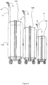
- FIG. 10A The figures show an embodiment of a connectable suitcase 10A, 10B, 10C in accordance with the present invention.
- the connectable suitcases 10A, 10B, 10C can be of different sizes, or alternatively, may be of the same size. Regardless of the size of the suitcases, the construction of each is the same for the purpose of the present disclosure. The following description refers to the suitcase 10A for ease of reference.
- each suitcase 10A, 10B, 10C can be connected front to back. Whilst the figures show largest to smallest (10A, 10B, 10C) the suitcases 10A, 10B, 10C may be connected in any order. For example, the larger suitcase 10A may be in front of the medium suitcase 10B, or two (or more) suitcases of the same size may be connected together.
- the suitcases 10A, 10B, 10C are of the hard shell type and each has a set of wheels 12A, 12B, 12C at a base 11A, 11B, 11C thereof for rolling the suitcases 10A, 10B, 10C on the ground.
- the front pair of wheels 13 of each suitcase 10A, 10B, 10C are positioned closer to centre than the rear pair of wheels 15. This allows the front pair of wheels 13 of the rear suitcase 10A to nest between the rear pair of wheels 15 of the front suitcase 10B such that the wheels 12 are not inhibited when the suitcases 10A, 10B are connected together, and the suitcases 10A, 10B roll easily.
- the wheels 12 may be detachable and available in aesthetically pleasing colours such as fluorescent yellow, green or orange.
- Each suitcase 10A, 10B, 10C has a retractable handle 14, 114 which can be moved by the user of the suitcase between a retracted position ( Figure 10 ) and an extended position ( Figure 11 ) in which the handle 14, 114 can be pulled behind a user such that the suitcase 10A, 10B, 10C can roll over the ground.
- Figures 1 and 2 show a first embodiment of the retractable handle 14 being a T-shape.
- the handle 14 includes a first portion 16 and a second portion 17.
- the second portion 17 is extendable generally vertically from a top portion of the suitcase 10A, 10B, 10C and the first portion extends at an angle rearward of the suitcase 10A, 10B, 10C.
- FIG. 3 shows the handle 114 extended and Figure 4 shows a rear view of a suitcase 10A with the handle 114 retracted.
- the handle 14 is generally 'U' shaped, having a pair of telescopic side arms 116 and a central gripping portion 115 the spans the width of the suitcase 10A.
- Each side arm 116 is pivotably at each end 117 and is pivotable between a generally vertical position for retraction within the suitcase 10A, and an angled position ( Figure 11 ) to allow both pairs of wheels 13, 15 to remain in contact with ground for ease of movement, and there is no need for a user to tilt the suitcase 10A to roll it along the ground. Both the front pair 13 and the rear pair 15 of wheels remain on the ground as the suitcase is pulled over the ground.
- the handle 114 is in the retracted position as shown in Figure 10 , the telescopic arms 116 are retracted such that the central gripping portion 115 lies flush with an upper surface 111 of the suitcase 10A.
- the telescopic arms 116 When in the extended position as seen in Figures 11 and 12 , the telescopic arms 116 are fully extended in an upright position.
- the telescopic arms 116 each include a pivotable hinge 117 at a base thereof.
- the pivotable hinge 117 allows the handle 114 to be tilted away from the suitcase 10A so that the user can comfortably pull it without having to tilt the suitcase 10A.
- the wide handle design of this embodiment provides lateral stability to the suitcase that allows multiple connected suitcases to be transported together as a unit without over-stressing the handle mechanism.
- the suitcase 10A has a front surface 20A and a rear surface 30A.
- the front surface 20A has a first connecting portion 40A and the rear surface 30A has a second connecting portion 70A.
- the first connecting portion 40A of the suitcase 10A will connect with the second connecting portion 70A of a like suitcase 10 to form a single unit for transport.
- the connection portions 40A and 70A are positioned on the suitcase 10A such that the order of the suitcases is not essential. For example, a larger suitcase 10A may be connected in front of a medium suitcase 10B or vice versa.
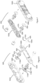
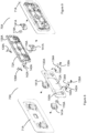
- Figures 6 and 7 show exploded front and rear views respectively of a first connecting portion 40A.
- the first connecting portion 40A includes a locking plate 102A mountable to an inner surface of the suitcase 10A and a bracing plate 100A mountable on an outer surface of the suitcase 10A.
- the locking plate 102A and the bracing plate 100A are joined together via fasteners (not shown) such as screws to sandwich the front surface 20A of the suitcase 10A therebetween and to house the connecting components described below.
- the first connecting portion 40A includes a lock plug 104A being a tubular housing 41A having an end wall 42A at a distal end thereof having a slightly larger diameter than that of the housing 41A to create a flange 43A.
- Ring magnet 60A and compression spring 117A are positioned using retainer 50A.
- Retainer 50A includes a circular base 110A circumscribed by a rim 112A and a conical arm 114A extending from the base 110A. Ribs 116A extend from the base 110A along the arm 114A terminating at a top surface of the arm 116A.
- the arm 114A includes a threaded aperture 118A.
- Retainer 50A locates the spring 117A inside the rim 112A and prevents lateral movement of the spring 47A. Retainer 50A also keeps the magnet 60A positioned.
- a circular rim 117A located on the top surface of the arm 116A has a diameter slightly smaller than the inner diameter of the ring magnet 60A and abuts within the inner diameter to securely position the magnet 60A in place.
- the tubular housing 41A is fed through the aperture 106A in the locking plate 102A and the magnet 60A, the spring 117A is assembled within the tubular housing 41A.
- the arm 114A of the retainer 50A is inserted through the spring 47A and is used to locate the magnet 60A so that it abuts the end wall 42A of the cover 104A.
- a self-tapping screw 108A secures the retainer 50A to the tubular housing 41A.
- the bracing plate 100A includes a reinforcement rib 120A extending between each magnetic assembly 122A allowing the bracing plate 100A to be load bearing thus taking load away from each magnetic assembly 122A.
- the bracing plate 100A and locking plate 102A allow for ease of assembly and ensure correct alignment during the closing action.
- the compression spring 47A is biased in a rest position at which the cover 104A is in a retracted position in which the proximal end 17 of the tubular housing 41A and the endcap 48A protrude into the front surface 20A of the suitcase 10A and the end wall 42A lies flush with the front surface 20A.
- the ring magnet 60A forces the end wall 42A distally into an extended position, overcoming the spring force of the compression spring 47A and contracting the spring 47A.
- FIGS 8 and 9 show front and rear views, respectively, of the second connecting portion 70A.
- the second connecting portion 70A includes a brace plate 71A and a face plate 130A.
- the brace plate 71A and the face plate 130A cooperate to sandwich a rear surface of the suitcase 10A in a similar manner to the first connecting portion 40A.
- the brace plate 71A and the face plate 130A house a pair of second magnetic assemblies 119A.
- the face plate 130A has a sunken central recess 72A and two side recesses 144A.
- Each side recess 144A is adapted to receive a respective cover 104A of the first connecting portion 70A.
- Each side recess 144A is generally rectangular shaped with a bottom curved portion 148A for receiving the cover 104A.
- a ramp section 150A facilitates a smooth motion when connecting to another suitcase 10.
- the brace plate 71A is adapted to be installed at an interior side of the rear surface 30A of the suitcase 10A
- the face plate 130A is adapted to be installed at an exterior side of the rear surface 30A so that assembled the two plates 71A, 130A sandwich the rear surface 30A of the suitcase 10A.
- a spring locking element 134A is attached within each recess 144A of the face plate 130A.
- the spring locking element 134A includes a first arm 138A and a second arm 140A which are snap fit together.
- a torsion spring 142A sits inside the assembled arms 138A, 140A to urge the arms 138A, 140A together.
- the spring locking element 134A flexes open to receive the tubular housing 41A of the first connection portion 40A and the torsion spring 142A urges the arms 138A, 140A closed to lock the tubular housing 41A in position.
- the spring locking element 134A provides positive feedback of locking and requires minimal effort to connect.
- a screw 146A is used to attach a rear housing 141A and ring magnet 119A to the face plate 130A.
- Fixing holes 73A and fasteners are used to attach the face plate 130A to the brace plate 71A.
- the first connecting portion 40A is installed in a front surface 20A of a suitcase 10A as seen in Figure 12 .
- the second connecting portion 70B is installed in a rear surface 30B of a suitcase 10B as seen in Figure 4 .
- the front surface 20A of suitcase 10A is brought into close proximity with the rear surface 70B of suitcase 10B.
- the first connecting portion 40A of the connector and the second connecting portion 70B of the connector are installed at the same height above the bases 11A, 11B of the suitcases 10A, 10B such that they line up with one another when the suitcases 10A, 10B are placed next to one another as shown schematically in Figure 13(1) and Figure 14(1).
- the magnets 60A and 136A are of opposite magnetic poles such that they attract one another in close proximity.
- Figure 13 shows the first magnetic assembly 122A and the second magnetic assembly 119A of the magnetic connector disengaged.
- the first magnetic assembly 122A includes a spring driven retracting plug or cover with a locking piece (undercut) 104A and one magnet 60A and magnet retainer 50A.
- the second magnetic assembly 119A includes a spring locking element 134A, a magnet 136A and a magnet retainer 132A.
- Figure 14 shows the first magnetic assembly 122A and the second magnetic assembly 119A.
- the connecting portions 40A, 70A are located by magnetic attraction and secured by mechanical fastening. Positioning the connections portions 40A, 70A in close proximity results in the cover 104A from connection portion 40A advancing toward the second connecting portion 70A.
- the spring locking element 134A from the second connecting portion 70A deflects to allow the cover 104A from the first connecting portion 40A to pass through and enter the locked position.
- the torsion spring 142A allows the spring locking element 134A to flex open and then close as the lock plug 104A enters the locking position. This provides good feedback and less effort to connect the suitcases 10.
- the suitcase 10A is lifted vertically by a small amount to disengage the magnets 122A, 119A.
- Ramp 150A provides for a smooth unlocking motion.
- the magnetic connector may be used to lock together other units such as soft shell suitcases, golf bags or other sporting equipment bags or storage units.
- the connector is a quick-release connector or latch mechanism.
Landscapes
- Purses, Travelling Bags, Baskets, Or Suitcases (AREA)
Claims (4)
- Koffer (10), der mit einem anderen Koffer verbindbar ist, wobei der Koffer beinhaltet:einen ersten Verbindungsabschnitt (40A), der auf einer Vorderseite (20A) des Koffers angeordnet ist;einen zweiten Verbindungsabschnitt (70A), der an einer Rückseite (30A) des Koffers angeordnet ist, wobei der erste Verbindungsabschnitt funktionell mit dem zweiten Verbindungsabschnitt verbunden ist, um mindestens zwei Koffer Vorder- an Rückseite zu verbinden, wobei der erste und der zweite Verbindungsabschnitt magnetisch sind und sich anziehen, um miteinander zu verriegeln;ein vorderes Paar Räder (13), die entlang einer ersten Achse montiert sind;ein hinteres Paar Räder (15), das entlang einer zweiten Achse parallel zur ersten Achse angebracht ist,dadurch gekennzeichnet, dass das vordere Paar Räder seitlich um einen ersten Abstand beabstandet ist und das hintere Paar Räder seitlich um einen zweiten Abstand beabstandet ist, der größer als der erste Abstand ist, so dass, wenn die mindestens zwei Koffer Vorder- an Rückseite verbunden sind, das vordere Paar Räder des hinteren Koffers zwischen das hintere Paar Räder des vorderen Koffers passt,und dass der erste Verbindungsabschnitt (40A) des Magnetverbinders ein Gehäuse (41A), das zwei Verschlussmodule (102A; 100A) hat, wobei jedes Verschlussmodul eine Endwand (42A) an einem proximalen Ende desselben beinhaltet, mindestens einen Magneten (60A), der im Inneren des Gehäuses angeordnet ist, eine Endkappe (48A), die an dem Gehäuse (4IA) an einem distalen Ende desselben befestigt ist, und ein elastisches Vorspannmittel (117A), das über dem Gehäuse zwischen der Endwand (42A) und der Endkappe (48A) angeordnet ist, beinhaltet;und dass der zweite Verbindungsabschnitt (70A) des Magnetverbinders ein Gehäuse (141A) beinhaltet, das zwei komplementäre Verschlussmodule (71A; 130A) hat, wobei jedes Verschlussmodul mindestens einen Magneten (136A) hat, der innerhalb des Gehäuses (141A) angeordnet ist, wodurch bei der Verwendung des Magnetverbinders das elastische Vorspannmittel (117A) angepasst ist, um das Gehäuse und die Endwand (42A) des ersten Verbindungsabschnitts (40A) in eine erste zurückgezogene Position relativ zu dem zweiten Verbindungsabschnitt (70A) vorzuspannen, wenn der erste Verbindungsabschnitt (40A) und der zweite Verbindungsabschnitt (70A) nicht verbunden sind, und, wenn der erste Verbindungsabschnitt (40A) und der zweite Verbindungsabschnitt (70A) miteinander verbunden sind, sich unter einer von dem zweiten Verbindungsabschnitt (70A) ausgehenden magnetischen Kraft zusammenzuziehen, um zu bewirken, dass sich das Gehäuse und die Endwand (42A) des ersten Verbindungsabschnitts (40A) in eine zweite ausgefahrene Position relativ zu dem zweiten Verbindungsabschnitt (70A) bewegen, um mit diesem in Eingriff zu kommen.
- Koffer (10) nach Anspruch 1, der ferner einen Griff (14A) beinhaltet, der zwischen einer eingefahrenen Position und einer ausgefahrenen Position bewegbar ist, wobei der Griff schwenkbar mit dem Koffer verbunden ist, so dass der Griff in der ausgefahrenen Position in einem Winkel relativ zum Koffer schwenkbar ist.
- Koffer (10) nach Anspruch 2, wobei der Griff (14A) vom Koffer wegschwenkbar ist, damit sowohl das vordere als auch das hintere Räderpaar während der Bewegung den Boden berühren können.
- Koffer (10) nach Anspruch 2 oder 3, wobei der Griff (14A) ein Paar Teleskoparme (116) beinhaltet, die schwenkbar am Koffer angelenkt sind.
Applications Claiming Priority (2)
| Application Number | Priority Date | Filing Date | Title |
|---|---|---|---|
| AU2017903057A AU2017903057A0 (en) | 2017-08-02 | A connectable suitcase | |
| PCT/AU2018/000127 WO2019023736A1 (en) | 2017-08-02 | 2018-08-02 | CONNECTABLE CASE |
Publications (4)
| Publication Number | Publication Date |
|---|---|
| EP3661386A1 EP3661386A1 (de) | 2020-06-10 |
| EP3661386A4 EP3661386A4 (de) | 2021-04-07 |
| EP3661386B1 true EP3661386B1 (de) | 2023-10-25 |
| EP3661386C0 EP3661386C0 (de) | 2023-10-25 |
Family
ID=65232181
Family Applications (1)
| Application Number | Title | Priority Date | Filing Date |
|---|---|---|---|
| EP18840731.6A Active EP3661386B1 (de) | 2017-08-02 | 2018-08-02 | Koppelbarer koffer |
Country Status (9)
| Country | Link |
|---|---|
| US (1) | US11700925B2 (de) |
| EP (1) | EP3661386B1 (de) |
| JP (1) | JP7301049B2 (de) |
| CN (1) | CN111031838A (de) |
| AU (1) | AU2018310745B2 (de) |
| CA (1) | CA3070218C (de) |
| ES (1) | ES2966661T3 (de) |
| PL (1) | PL3661386T3 (de) |
| WO (1) | WO2019023736A1 (de) |
Families Citing this family (4)
| Publication number | Priority date | Publication date | Assignee | Title |
|---|---|---|---|---|
| US11896101B2 (en) * | 2020-04-16 | 2024-02-13 | Shakiba Rahimi | Luggage connecting assembly |
| US11622608B2 (en) * | 2021-03-29 | 2023-04-11 | Alan Samuelson | Luggage handle |
| GB2610873A (en) * | 2021-09-21 | 2023-03-22 | Vgi Holdings Ltd | Storage container and modular storage system |
| WO2025078572A1 (de) | 2023-10-12 | 2025-04-17 | Strub Alex Eric | Behälter, ausgeführt als reisekoffer, und zugehörige kombinationen von befestigungssystemen |
Citations (1)
| Publication number | Priority date | Publication date | Assignee | Title |
|---|---|---|---|---|
| WO1997018726A1 (en) * | 1995-11-22 | 1997-05-29 | Samsonite Corporation | Ergonomic upright wheeled luggage |
Family Cites Families (13)
| Publication number | Priority date | Publication date | Assignee | Title |
|---|---|---|---|---|
| EP0513450B1 (de) | 1991-05-17 | 1996-03-06 | KIKUCHI, Takeshi | Koppelbare Koffer |
| JP3528752B2 (ja) * | 2000-04-11 | 2004-05-24 | ヤマハ株式会社 | 可搬式収納ケース |
| US20080308370A1 (en) * | 2007-06-14 | 2008-12-18 | Kyong-Soo Chung | Push-pull wheeled luggage with swingable rear wheels and at least one fixed front wheel |
| US20080308369A1 (en) * | 2007-06-15 | 2008-12-18 | Louis Robert D | Luggage transport system |
| US20090057082A1 (en) * | 2007-08-31 | 2009-03-05 | Jeffrey Mize | Push suitcase |
| US20110247910A1 (en) * | 2010-04-12 | 2011-10-13 | Jenna Darvish | Luggage with Deployable Undercarriage |
| DE102010044144B3 (de) * | 2010-11-18 | 2012-05-31 | Fidlock Gmbh | Verschlussvorrichtung |
| US20130175129A1 (en) * | 2012-01-09 | 2013-07-11 | Travelpro International Inc. | System for Attaching Bags |
| ES2409529B1 (es) | 2013-03-14 | 2014-04-28 | Araven, S.L. | Carro de la compra |
| US20150014949A1 (en) * | 2013-04-08 | 2015-01-15 | Rick Terrell Dittman | Carrying Device Attachment |
| US9314076B2 (en) * | 2013-10-31 | 2016-04-19 | Colson Edme | Travel suitcase system |
| WO2015196238A1 (en) * | 2014-06-26 | 2015-12-30 | Rtl Group Investments Pty Ltd | A modular unit system |
| US20170181514A1 (en) * | 2015-12-28 | 2017-06-29 | Luis Castillo Machado | luggage Cart. |
-
2018
- 2018-08-02 EP EP18840731.6A patent/EP3661386B1/de active Active
- 2018-08-02 US US16/633,050 patent/US11700925B2/en active Active
- 2018-08-02 WO PCT/AU2018/000127 patent/WO2019023736A1/en not_active Ceased
- 2018-08-02 CA CA3070218A patent/CA3070218C/en active Active
- 2018-08-02 AU AU2018310745A patent/AU2018310745B2/en active Active
- 2018-08-02 CN CN201880050096.9A patent/CN111031838A/zh active Pending
- 2018-08-02 JP JP2020528496A patent/JP7301049B2/ja active Active
- 2018-08-02 ES ES18840731T patent/ES2966661T3/es active Active
- 2018-08-02 PL PL18840731.6T patent/PL3661386T3/pl unknown
Patent Citations (1)
| Publication number | Priority date | Publication date | Assignee | Title |
|---|---|---|---|---|
| WO1997018726A1 (en) * | 1995-11-22 | 1997-05-29 | Samsonite Corporation | Ergonomic upright wheeled luggage |
Also Published As
| Publication number | Publication date |
|---|---|
| EP3661386A1 (de) | 2020-06-10 |
| JP2020529299A (ja) | 2020-10-08 |
| US11700925B2 (en) | 2023-07-18 |
| CA3070218C (en) | 2023-10-03 |
| WO2019023736A1 (en) | 2019-02-07 |
| AU2018310745A1 (en) | 2020-02-06 |
| JP7301049B2 (ja) | 2023-06-30 |
| US20200205533A1 (en) | 2020-07-02 |
| EP3661386A4 (de) | 2021-04-07 |
| AU2018310745B2 (en) | 2024-08-15 |
| PL3661386T3 (pl) | 2024-03-18 |
| CN111031838A (zh) | 2020-04-17 |
| EP3661386C0 (de) | 2023-10-25 |
| ES2966661T3 (es) | 2024-04-23 |
| CA3070218A1 (en) | 2019-02-07 |
Similar Documents
| Publication | Publication Date | Title |
|---|---|---|
| EP3661386B1 (de) | Koppelbarer koffer | |
| US11192690B1 (en) | Utility assembly and coupling mechanism | |
| EP2172384B1 (de) | Pritschenwagen mit einklappbaren Laufrollen | |
| US7784816B2 (en) | Flat platform cart with collapsible casters | |
| USRE50761E1 (en) | Wheeled container handle assembly | |
| US20120326406A1 (en) | Modular rolling container assembly | |
| CN212165168U (zh) | 一种用于将部件附接到行李制品的卡扣配合互锁 | |
| US20190313752A1 (en) | Trolley case with front open | |
| US20220346514A1 (en) | Luggage article attachment member | |
| WO2015196238A1 (en) | A modular unit system | |
| US20100276242A1 (en) | Wheeled suitcase having dual extractable handle assemblies | |
| HK40027645A (en) | A connectable suitcase | |
| KR102349461B1 (ko) | 차량용 테이블 텐트 | |
| US20180333998A1 (en) | Quick hitch mount |
Legal Events
| Date | Code | Title | Description |
|---|---|---|---|
| STAA | Information on the status of an ep patent application or granted ep patent |
Free format text: STATUS: THE INTERNATIONAL PUBLICATION HAS BEEN MADE |
|
| PUAI | Public reference made under article 153(3) epc to a published international application that has entered the european phase |
Free format text: ORIGINAL CODE: 0009012 |
|
| STAA | Information on the status of an ep patent application or granted ep patent |
Free format text: STATUS: REQUEST FOR EXAMINATION WAS MADE |
|
| 17P | Request for examination filed |
Effective date: 20200117 |
|
| AK | Designated contracting states |
Kind code of ref document: A1 Designated state(s): AL AT BE BG CH CY CZ DE DK EE ES FI FR GB GR HR HU IE IS IT LI LT LU LV MC MK MT NL NO PL PT RO RS SE SI SK SM TR |
|
| AX | Request for extension of the european patent |
Extension state: BA ME |
|
| DAV | Request for validation of the european patent (deleted) | ||
| DAX | Request for extension of the european patent (deleted) | ||
| A4 | Supplementary search report drawn up and despatched |
Effective date: 20210311 |
|
| RIC1 | Information provided on ipc code assigned before grant |
Ipc: A45C 5/14 20060101AFI20210304BHEP Ipc: A45C 13/10 20060101ALI20210304BHEP Ipc: A45C 7/00 20060101ALI20210304BHEP |
|
| STAA | Information on the status of an ep patent application or granted ep patent |
Free format text: STATUS: EXAMINATION IS IN PROGRESS |
|
| 17Q | First examination report despatched |
Effective date: 20220124 |
|
| P01 | Opt-out of the competence of the unified patent court (upc) registered |
Effective date: 20230513 |
|
| GRAP | Despatch of communication of intention to grant a patent |
Free format text: ORIGINAL CODE: EPIDOSNIGR1 |
|
| STAA | Information on the status of an ep patent application or granted ep patent |
Free format text: STATUS: GRANT OF PATENT IS INTENDED |
|
| GRAS | Grant fee paid |
Free format text: ORIGINAL CODE: EPIDOSNIGR3 |
|
| GRAA | (expected) grant |
Free format text: ORIGINAL CODE: 0009210 |
|
| STAA | Information on the status of an ep patent application or granted ep patent |
Free format text: STATUS: THE PATENT HAS BEEN GRANTED |
|
| INTG | Intention to grant announced |
Effective date: 20230831 |
|
| AK | Designated contracting states |
Kind code of ref document: B1 Designated state(s): AL AT BE BG CH CY CZ DE DK EE ES FI FR GB GR HR HU IE IS IT LI LT LU LV MC MK MT NL NO PL PT RO RS SE SI SK SM TR |
|
| REG | Reference to a national code |
Ref country code: GB Ref legal event code: FG4D |
|
| REG | Reference to a national code |
Ref country code: CH Ref legal event code: EP |
|
| REG | Reference to a national code |
Ref country code: DE Ref legal event code: R096 Ref document number: 602018060105 Country of ref document: DE |
|
| REG | Reference to a national code |
Ref country code: IE Ref legal event code: FG4D |
|
| P04 | Withdrawal of opt-out of the competence of the unified patent court (upc) registered |
Effective date: 20231113 |
|
| U01 | Request for unitary effect filed |
Effective date: 20231109 |
|
| U07 | Unitary effect registered |
Designated state(s): AT BE BG DE DK EE FI FR IT LT LU LV MT NL PT SE SI Effective date: 20231116 |
|
| PG25 | Lapsed in a contracting state [announced via postgrant information from national office to epo] |
Ref country code: GR Free format text: LAPSE BECAUSE OF FAILURE TO SUBMIT A TRANSLATION OF THE DESCRIPTION OR TO PAY THE FEE WITHIN THE PRESCRIBED TIME-LIMIT Effective date: 20240126 |
|
| PG25 | Lapsed in a contracting state [announced via postgrant information from national office to epo] |
Ref country code: IS Free format text: LAPSE BECAUSE OF FAILURE TO SUBMIT A TRANSLATION OF THE DESCRIPTION OR TO PAY THE FEE WITHIN THE PRESCRIBED TIME-LIMIT Effective date: 20240225 |
|
| REG | Reference to a national code |
Ref country code: ES Ref legal event code: FG2A Ref document number: 2966661 Country of ref document: ES Kind code of ref document: T3 Effective date: 20240423 |
|
| PG25 | Lapsed in a contracting state [announced via postgrant information from national office to epo] |
Ref country code: IS Free format text: LAPSE BECAUSE OF FAILURE TO SUBMIT A TRANSLATION OF THE DESCRIPTION OR TO PAY THE FEE WITHIN THE PRESCRIBED TIME-LIMIT Effective date: 20240225 Ref country code: GR Free format text: LAPSE BECAUSE OF FAILURE TO SUBMIT A TRANSLATION OF THE DESCRIPTION OR TO PAY THE FEE WITHIN THE PRESCRIBED TIME-LIMIT Effective date: 20240126 |
|
| PG25 | Lapsed in a contracting state [announced via postgrant information from national office to epo] |
Ref country code: RS Free format text: LAPSE BECAUSE OF FAILURE TO SUBMIT A TRANSLATION OF THE DESCRIPTION OR TO PAY THE FEE WITHIN THE PRESCRIBED TIME-LIMIT Effective date: 20231025 Ref country code: NO Free format text: LAPSE BECAUSE OF FAILURE TO SUBMIT A TRANSLATION OF THE DESCRIPTION OR TO PAY THE FEE WITHIN THE PRESCRIBED TIME-LIMIT Effective date: 20240125 Ref country code: HR Free format text: LAPSE BECAUSE OF FAILURE TO SUBMIT A TRANSLATION OF THE DESCRIPTION OR TO PAY THE FEE WITHIN THE PRESCRIBED TIME-LIMIT Effective date: 20231025 |
|
| PG25 | Lapsed in a contracting state [announced via postgrant information from national office to epo] |
Ref country code: CZ Free format text: LAPSE BECAUSE OF FAILURE TO SUBMIT A TRANSLATION OF THE DESCRIPTION OR TO PAY THE FEE WITHIN THE PRESCRIBED TIME-LIMIT Effective date: 20231025 |
|
| REG | Reference to a national code |
Ref country code: DE Ref legal event code: R097 Ref document number: 602018060105 Country of ref document: DE |
|
| PG25 | Lapsed in a contracting state [announced via postgrant information from national office to epo] |
Ref country code: SK Free format text: LAPSE BECAUSE OF FAILURE TO SUBMIT A TRANSLATION OF THE DESCRIPTION OR TO PAY THE FEE WITHIN THE PRESCRIBED TIME-LIMIT Effective date: 20231025 |
|
| PG25 | Lapsed in a contracting state [announced via postgrant information from national office to epo] |
Ref country code: SM Free format text: LAPSE BECAUSE OF FAILURE TO SUBMIT A TRANSLATION OF THE DESCRIPTION OR TO PAY THE FEE WITHIN THE PRESCRIBED TIME-LIMIT Effective date: 20231025 Ref country code: SK Free format text: LAPSE BECAUSE OF FAILURE TO SUBMIT A TRANSLATION OF THE DESCRIPTION OR TO PAY THE FEE WITHIN THE PRESCRIBED TIME-LIMIT Effective date: 20231025 Ref country code: CZ Free format text: LAPSE BECAUSE OF FAILURE TO SUBMIT A TRANSLATION OF THE DESCRIPTION OR TO PAY THE FEE WITHIN THE PRESCRIBED TIME-LIMIT Effective date: 20231025 |
|
| PLBE | No opposition filed within time limit |
Free format text: ORIGINAL CODE: 0009261 |
|
| STAA | Information on the status of an ep patent application or granted ep patent |
Free format text: STATUS: NO OPPOSITION FILED WITHIN TIME LIMIT |
|
| U20 | Renewal fee for the european patent with unitary effect paid |
Year of fee payment: 7 Effective date: 20240807 |
|
| 26N | No opposition filed |
Effective date: 20240726 |
|
| P05 | Withdrawal of opt-out of the competence of the unified patent court (upc) changed |
Free format text: CASE NUMBER: APP_586997/2023 Effective date: 20231116 |
|
| PG25 | Lapsed in a contracting state [announced via postgrant information from national office to epo] |
Ref country code: MC Free format text: LAPSE BECAUSE OF FAILURE TO SUBMIT A TRANSLATION OF THE DESCRIPTION OR TO PAY THE FEE WITHIN THE PRESCRIBED TIME-LIMIT Effective date: 20231025 |
|
| PG25 | Lapsed in a contracting state [announced via postgrant information from national office to epo] |
Ref country code: IE Free format text: LAPSE BECAUSE OF NON-PAYMENT OF DUE FEES Effective date: 20240802 |
|
| U20 | Renewal fee for the european patent with unitary effect paid |
Year of fee payment: 8 Effective date: 20250707 |
|
| PGFP | Annual fee paid to national office [announced via postgrant information from national office to epo] |
Ref country code: ES Payment date: 20250926 Year of fee payment: 8 |
|
| PGFP | Annual fee paid to national office [announced via postgrant information from national office to epo] |
Ref country code: PL Payment date: 20250729 Year of fee payment: 8 Ref country code: TR Payment date: 20250728 Year of fee payment: 8 |
|
| PGFP | Annual fee paid to national office [announced via postgrant information from national office to epo] |
Ref country code: GB Payment date: 20250704 Year of fee payment: 8 |
|
| PGFP | Annual fee paid to national office [announced via postgrant information from national office to epo] |
Ref country code: CH Payment date: 20250901 Year of fee payment: 8 |
|
| PGFP | Annual fee paid to national office [announced via postgrant information from national office to epo] |
Ref country code: RO Payment date: 20250725 Year of fee payment: 8 |
|
| PG25 | Lapsed in a contracting state [announced via postgrant information from national office to epo] |
Ref country code: CY Free format text: LAPSE BECAUSE OF FAILURE TO SUBMIT A TRANSLATION OF THE DESCRIPTION OR TO PAY THE FEE WITHIN THE PRESCRIBED TIME-LIMIT; INVALID AB INITIO Effective date: 20180802 |
|
| PG25 | Lapsed in a contracting state [announced via postgrant information from national office to epo] |
Ref country code: HU Free format text: LAPSE BECAUSE OF FAILURE TO SUBMIT A TRANSLATION OF THE DESCRIPTION OR TO PAY THE FEE WITHIN THE PRESCRIBED TIME-LIMIT; INVALID AB INITIO Effective date: 20180802 |