EP3661335B1 - Vario-energy electron accelerator - Google Patents
Vario-energy electron accelerator Download PDFInfo
- Publication number
- EP3661335B1 EP3661335B1 EP18208924.3A EP18208924A EP3661335B1 EP 3661335 B1 EP3661335 B1 EP 3661335B1 EP 18208924 A EP18208924 A EP 18208924A EP 3661335 B1 EP3661335 B1 EP 3661335B1
- Authority
- EP
- European Patent Office
- Prior art keywords
- electron beam
- deflecting
- resonant cavity
- trajectory
- central axis
- Prior art date
- Legal status (The legal status is an assumption and is not a legal conclusion. Google has not performed a legal analysis and makes no representation as to the accuracy of the status listed.)
- Active
Links
Images


Classifications
-
- H—ELECTRICITY
- H05—ELECTRIC TECHNIQUES NOT OTHERWISE PROVIDED FOR
- H05H—PLASMA TECHNIQUE; PRODUCTION OF ACCELERATED ELECTRICALLY-CHARGED PARTICLES OR OF NEUTRONS; PRODUCTION OR ACCELERATION OF NEUTRAL MOLECULAR OR ATOMIC BEAMS
- H05H13/00—Magnetic resonance accelerators; Cyclotrons
- H05H13/10—Accelerators comprising one or more linear accelerating sections and bending magnets or the like to return the charged particles in a trajectory parallel to the first accelerating section, e.g. microtrons or rhodotrons
-
- G—PHYSICS
- G21—NUCLEAR PHYSICS; NUCLEAR ENGINEERING
- G21K—TECHNIQUES FOR HANDLING PARTICLES OR IONISING RADIATION NOT OTHERWISE PROVIDED FOR; IRRADIATION DEVICES; GAMMA RAY OR X-RAY MICROSCOPES
- G21K1/00—Arrangements for handling particles or ionising radiation, e.g. focusing or moderating
- G21K1/08—Deviation, concentration or focusing of the beam by electric or magnetic means
- G21K1/093—Deviation, concentration or focusing of the beam by electric or magnetic means by magnetic means
-
- G—PHYSICS
- G21—NUCLEAR PHYSICS; NUCLEAR ENGINEERING
- G21K—TECHNIQUES FOR HANDLING PARTICLES OR IONISING RADIATION NOT OTHERWISE PROVIDED FOR; IRRADIATION DEVICES; GAMMA RAY OR X-RAY MICROSCOPES
- G21K5/00—Irradiation devices
- G21K5/04—Irradiation devices with beam-forming means
-
- H—ELECTRICITY
- H05—ELECTRIC TECHNIQUES NOT OTHERWISE PROVIDED FOR
- H05H—PLASMA TECHNIQUE; PRODUCTION OF ACCELERATED ELECTRICALLY-CHARGED PARTICLES OR OF NEUTRONS; PRODUCTION OR ACCELERATION OF NEUTRAL MOLECULAR OR ATOMIC BEAMS
- H05H7/00—Details of devices of the types covered by groups H05H9/00, H05H11/00, H05H13/00
- H05H7/02—Circuits or systems for supplying or feeding radio-frequency energy
-
- H—ELECTRICITY
- H05—ELECTRIC TECHNIQUES NOT OTHERWISE PROVIDED FOR
- H05H—PLASMA TECHNIQUE; PRODUCTION OF ACCELERATED ELECTRICALLY-CHARGED PARTICLES OR OF NEUTRONS; PRODUCTION OR ACCELERATION OF NEUTRAL MOLECULAR OR ATOMIC BEAMS
- H05H7/00—Details of devices of the types covered by groups H05H9/00, H05H11/00, H05H13/00
- H05H7/04—Magnet systems, e.g. undulators, wigglers; Energisation thereof
-
- H—ELECTRICITY
- H05—ELECTRIC TECHNIQUES NOT OTHERWISE PROVIDED FOR
- H05H—PLASMA TECHNIQUE; PRODUCTION OF ACCELERATED ELECTRICALLY-CHARGED PARTICLES OR OF NEUTRONS; PRODUCTION OR ACCELERATION OF NEUTRAL MOLECULAR OR ATOMIC BEAMS
- H05H7/00—Details of devices of the types covered by groups H05H9/00, H05H11/00, H05H13/00
- H05H7/08—Arrangements for injecting particles into orbits
-
- H—ELECTRICITY
- H05—ELECTRIC TECHNIQUES NOT OTHERWISE PROVIDED FOR
- H05H—PLASMA TECHNIQUE; PRODUCTION OF ACCELERATED ELECTRICALLY-CHARGED PARTICLES OR OF NEUTRONS; PRODUCTION OR ACCELERATION OF NEUTRAL MOLECULAR OR ATOMIC BEAMS
- H05H7/00—Details of devices of the types covered by groups H05H9/00, H05H11/00, H05H13/00
- H05H7/001—Arrangements for beam delivery or irradiation
- H05H2007/004—Arrangements for beam delivery or irradiation for modifying beam energy, e.g. spread out Bragg peak devices
-
- H—ELECTRICITY
- H05—ELECTRIC TECHNIQUES NOT OTHERWISE PROVIDED FOR
- H05H—PLASMA TECHNIQUE; PRODUCTION OF ACCELERATED ELECTRICALLY-CHARGED PARTICLES OR OF NEUTRONS; PRODUCTION OR ACCELERATION OF NEUTRAL MOLECULAR OR ATOMIC BEAMS
- H05H7/00—Details of devices of the types covered by groups H05H9/00, H05H11/00, H05H13/00
- H05H7/02—Circuits or systems for supplying or feeding radio-frequency energy
- H05H2007/025—Radiofrequency systems
-
- H—ELECTRICITY
- H05—ELECTRIC TECHNIQUES NOT OTHERWISE PROVIDED FOR
- H05H—PLASMA TECHNIQUE; PRODUCTION OF ACCELERATED ELECTRICALLY-CHARGED PARTICLES OR OF NEUTRONS; PRODUCTION OR ACCELERATION OF NEUTRAL MOLECULAR OR ATOMIC BEAMS
- H05H7/00—Details of devices of the types covered by groups H05H9/00, H05H11/00, H05H13/00
- H05H7/04—Magnet systems, e.g. undulators, wigglers; Energisation thereof
- H05H2007/045—Magnet systems, e.g. undulators, wigglers; Energisation thereof for beam bending
-
- H—ELECTRICITY
- H05—ELECTRIC TECHNIQUES NOT OTHERWISE PROVIDED FOR
- H05H—PLASMA TECHNIQUE; PRODUCTION OF ACCELERATED ELECTRICALLY-CHARGED PARTICLES OR OF NEUTRONS; PRODUCTION OR ACCELERATION OF NEUTRAL MOLECULAR OR ATOMIC BEAMS
- H05H7/00—Details of devices of the types covered by groups H05H9/00, H05H11/00, H05H13/00
- H05H7/04—Magnet systems, e.g. undulators, wigglers; Energisation thereof
- H05H2007/046—Magnet systems, e.g. undulators, wigglers; Energisation thereof for beam deflection
-
- H—ELECTRICITY
- H05—ELECTRIC TECHNIQUES NOT OTHERWISE PROVIDED FOR
- H05H—PLASMA TECHNIQUE; PRODUCTION OF ACCELERATED ELECTRICALLY-CHARGED PARTICLES OR OF NEUTRONS; PRODUCTION OR ACCELERATION OF NEUTRAL MOLECULAR OR ATOMIC BEAMS
- H05H7/00—Details of devices of the types covered by groups H05H9/00, H05H11/00, H05H13/00
- H05H7/08—Arrangements for injecting particles into orbits
- H05H2007/081—Sources
- H05H2007/084—Electron sources
-
- H—ELECTRICITY
- H05—ELECTRIC TECHNIQUES NOT OTHERWISE PROVIDED FOR
- H05H—PLASMA TECHNIQUE; PRODUCTION OF ACCELERATED ELECTRICALLY-CHARGED PARTICLES OR OF NEUTRONS; PRODUCTION OR ACCELERATION OF NEUTRAL MOLECULAR OR ATOMIC BEAMS
- H05H7/00—Details of devices of the types covered by groups H05H9/00, H05H11/00, H05H13/00
- H05H7/14—Vacuum chambers
- H05H7/18—Cavities; Resonators
Definitions
- the present invention relates to an electron accelerator having a resonant cavity centred on a central axis, Zc, and creating an oscillating electric field used for accelerating electrons along several radial trajectories forming the petals of a flower.
- a Rhodotron® is an example of such electron accelerator.
- An electron accelerator according to the present invention can extract an electron beam of different energies along a single path..
- Electron accelerators having a resonant cavity are well known in the art.
- EP0359774 describes an electron accelerator comprising:
- the electrons of an electron beam are accelerated along the diameter (two radii, 2R) of the resonant cavity by the electric field, E, generated by the RF system between the outer conductor section and inner conductor section and between the inner conductor section and outer conductor section.
- the oscillating electric field, E first accelerates electrons over the distance between the outer conductor section and inner conductor section.
- the polarity of the electric field changes when the electrons cross the area around the centre of the resonant cavity comprised within the inner cylindrical portion. This area around the centre of the resonant cavity provides a shielding from the electric field to the electrons which continue their trajectory at a constant velocity.
- the electrons are accelerated again in the segment of their trajectory comprised between the inner conductor section and outer conductor section.
- the polarity of the electric field again changes when the electrons are deflected by an electromagnet.
- the process is then repeated as often as necessary for the electron beam to reach a target energy where it is discharged out of the rhodotron.
- the trajectory of the electrons in the mid-plane, Pm thus has the shape of a flower (see Figure 1 ). An accelerated electron beam can thus be extracted from the rhodotron with a given energy.
- a rhodotron can be combined to external equipment such as a beam line and a beam scanning system.
- Rhodotrons can be used in industrial applications including sterilization (e.g., of medical devices), polymer modification, polymer crosslinking, pulp processing, modification of crystals, improvement of semi-conductors, beam aided chemical reactions, cold pasteurization and preservation of food, detection and security purposes, treatment of waste materials, etc.
- X-rays can also be produced by running an electron beam of appropriate energy into a metal target. X-rays can be used in different applications such as for example, (medical) radio-isotope production. The energies and intensity of the electron beams required are highly dependent on the application.
- electron beams of energy higher than 10 MeV are avoided to prevent induction and activation of nuclear reactions.
- X-rays are produced from electron beams of energy generally lower than 7.5 MeV.
- Electron beams of 7 MeV are usually well suited for sterilization of medical devices, surface sterilization, crosslinking of polymers, and the like. Food processing applications by electron beams can be broadly divided into,
- the problem with changing energies of the extracted electron beam with current accelerators is that the extraction path changes direction with each energy, depending on the number and positions of deflecting chambers which are added or removed.
- a target (100) intercepts a 7 MeV extracted electron beam along a first, rectilinear extraction trajectory, but if the same target (100) must be hit by a 5 MeV, the 5 MeV extracted electron beam must be deviated along a second, jagged trajectory to reach the target. Every deviation of the electron beam adds complexity and bulkiness of the system and increases production and installation costs.
- EP3319403 proposes a rhodotron mounted on a rack such that its angular orientation can be varied, to maintain the same orientation of the extracted electron beam, whilst the number of deflecting chambers is varied.
- CN 105578703 A discloses a rhodotron wherein two magnets are arranged one after the other along the beam path in a radial direction. By switching off the inner magnet, the electron beam is deflected by the outer magnet, thus increasing the length of the beam path. This allows to extract electron beams of different energies along a single electron path.
- the present invention also proposes a rhodotron capable of extracting electron beams of different energies along a single extraction path.
- the change of extraction energy is easy, quick and reliable and it can be discrete or continuous.
- This solution can be implemented to rhodotrons of any size, energy, and power and can also be implemented to existing rhodotron units by a simple modification.
- the present invention defines an electron accelerator according to claim 1. Preferred embodiments of the present invention efined in the dependent claims. In particular, the present invention defines an electron accelerator comprising:
- the moving means can comprise a motor for displacing back and forth the at least one moving vario-magnet unit along the corresponding bisecting direction.
- the second length (L2) is preferably such that when the electron beam is reintroduced into the resonant cavity, the RF system is synchronized for applying an electric field for decelerating the electron beam along the second radial trajectory.
- the at least one vario-magnet unit is a discrete vario-magnet dual unit comprising,
- first and second set of magnets are preferably adapted for generating a magnetic field
- the electron accelerator can further comprise deflectors,
- deflectors has the advantage that the gyroradius of the electron beam, and therefore the magnitude of the magnetic field, needs not be varied with the radial distance of neither first and second sets of magnets, nor of the moving vario-magnet.
- a preferred embodiment of the present invention is a that j comprises a single vario-magnet unit, which is positioned directly upstream of the outlet.
- the rhodotron is characterized by an energy gain or loss by an electron beam upon one pass across the resonant cavity to an i th magnet unit or from an (i - 1) th magnet unit, defined as follows:
- Each of the N magnet units generates a magnetic field in the deflecting chamber preferably comprised between 0.01 T and 1.3 T, more preferably from 0.02 T to 0.7 T.
- the electron beam can have an average power comprised between 30 and 700 kW, preferably between 150 and 650 kW.
- the resonant cavity is formed by:
- Figures 1 , 2(b2) & (c2) , and 4 show an example of a rhodotron comprising:
- the resonant cavity (1) comprises:
- the resonant cavity (1) is divided into two symmetrical parts with respect to the mid-plane, Pm. This symmetry of the resonant cavity with respect to the mid-plane concerns the geometry of the resonant cavity and ignores the presence of any openings, e.g., for connecting the RF system (70) or the vacuum system.
- the inner surface of the resonant cavity thus forms a hollow closed conductor in the shape of a toroidal volume.
- the height of the resonant cavity measured along the central axis, Zc is generally 1/2 ⁇ , where ⁇ is the RF wavelength.
- the diameter of the resonant cavity, measured normal to the central axis, Zc can be 0.72 ⁇ to allow transit in the deflecting chambers.
- the mid-plane, Pm can be vertical, horizontal or have any suitable orientations with respect to the ground on which the rhodotron rests. Preferably, it is horizontal or vertical.
- the resonant cavity (1) may comprise openings for connecting the RF system and the vacuum system (not shown). These openings are preferably made in at least one of the two bottom lids (11b, 12b).
- the outer wall also comprises apertures intersected by the mid-plane, Pm.
- the outer wall comprises an introduction inlet opening for introducing an electron beam (40) in the resonant cavity (1). It also comprises an electron beam outlet (50) for discharging out of the resonant cavity the electron beam (40-5 to 40-7) accelerated to a desired energy. It also comprises cavity outlet / inlet apertures (31w), bringing in fluid communication the resonant cavity with corresponding deflecting chamber (31, see below).
- a rhodotron comprises several magnet units and several cavity outlet / inlet apertures.
- a rhodotron generally accelerates the electrons of an electron beam to energies which can be comprised between 1 and 50 MeV, preferably between 3 and 20 MeV, more preferably between 5 and 10 MeV. As discussed supra, to avoid nuclear reactions, energies of not more than 10 MeV are applied in most industrial applications. Electrons are relativistic and at 50 keV they reach 0.4 c (wherein c is the light speed), at 1 MeV, they reach about 0.94 c and at 10 MeV they reach 0.9988 c. After one passage across the resonant cavity, the velocity of the electrons at an energy of typically 1 MeV can safely be approximated as being substantially constant.
- Rhodotrons have a high average power, which can be comprised between 30 to 700 kW, preferably between 150 and 650 kW, more preferably between 160 and 190 kW.
- IBA's rhodotron model TT50 can extract a beam of energy of up to 10 MeVaverage power comprised between 1 and 10 kW.
- the TT50 has a resonant cavity of 0.6 m diameter and accelerates the electron beam by an energy gain, wi, per passage of 1 MeV / pass.
- IBA's rhodotron model TT100 can extract electron beams of energy comprised between 3 and 10 MeV, with an energy gain, wi, per passage of 0.83 MeV / pass at a power of up to 40 kW.
- the inner wall comprises openings radially aligned with corresponding cavity outlet / inlet apertures (31 w) permitting the passage of an electron beam through the inner cylindrical portion along a rectilinear radial trajectory (intersecting the central axis, Zc).
- the surface of the resonant cavity (1) consisting of a hollow closed conductor is made of a conductive material.
- the conductive material can be one of gold, silver, platinum, aluminium, preferably copper.
- the outer and inner walls and bottom lids can be made of steel coated with a layer of conductive material.
- the resonant cavity (1) may have a diameter, 2R, comprised between 0.3 m and 4 m, preferably between 0.4 m and 3 m, more preferably between 0.5 m and 2 m.
- the height of the resonant cavity (1), measured parallel to the central axis, Zc, can be comprised between 0.3 m and 4 m, preferably between 0.4 m and 1.2 m, more preferably between 0.5 m and 0.7 m.
- the outer diameter of a rhodotron including a resonant cavity (1), an electron source (20), a vacuum system, a RF system, and one or more magnet units (30i), measured parallel to the mid-plane, Pm, may be comprised between 1 and 5 m, preferably between 1.2 and 2.8 m, more preferably between 1.4 and 1.8 m.
- the height of the rhodotron measured parallel to the central axis, Zc may be comprised between 0.5 and 5 m, preferably between 0.6 and 1.5 m, more preferably between 0.7 and 1.4 m.
- Electron Source Vacuum System, and RF system
- the electron source (20) is adapted for generating and for introducing an electron beam (40) into the resonant cavity along the mid-plane, Pm, towards the central axis, Zc, through an introduction inlet opening.
- the electron source may be an electron gun.
- an electron gun is an electrical component that produces a narrow, collimated electron beam that has a precise kinetic energy.
- the vacuum system comprises a vacuum pump for pumping air out of the resonant cavity (1) and creating a vacuum therein.
- the RF system is coupled to the resonant cavity (1) via a coupler and typically comprises an oscillator designed for oscillating at a resonant frequency, f RF , for generating an RF signal of wavelength, ⁇ , followed by an amplifier or a chain of amplifiers for achieving a desired output power at the end of the chain.
- the RF system thus generates a resonant radial electric field, E, in the resonant cavity.
- the resonant radial electric field, E oscillates such as to accelerate the electrons of the electron beam (40) along a trajectory lying in the mid-plane, Pm, from the outer conductor section towards the inner conductor section, and, subsequently, from the inner conductor section towards a cavity outlet aperture (31w).
- the resonant radial electric field, E is generally of the "TE001" type, which defines that the electric field is transverse (“TE"), has a symmetry of revolution (first "0"), is not cancelled out along one radius of the cavity (second “0”), and is a half-cycle of said field in a direction parallel to the central axis Z.
- N magnet units (30i) are distributed around an external circumference of the outer wall, and centred on the mid-plane Pm, with N > 1 and N ⁇ N.
- Each one of the N magnet units comprises a set of deflecting magnets adapted for generating a magnetic field in a deflecting chamber (31).
- the deflecting chamber is in fluid communication with the resonant cavity (1) by a cavity outlet aperture and a cavity inlet aperture, which can be separate apertures or merge in a single aperture, all referred to by the numeral (31w). All the deflecting chamber enclose a portion of the mid-plane Pm.
- N is equal to the total number of magnet units and is comprised between 1 and 15, preferably between 4 and 12, more preferably between 5 and 10.
- the number N of magnet units yield (N + 1) accelerations of the electrons of an electron beam (40) before it exits the rhodotron with a given energy (N + 1)*wi, wherein wi is the energy gained or lost by an electron beam upon one pass across the resonant cavity to a magnet unit (30i) or from a magnet unit (30(i- 1)).
- the magnetic field generated in each deflecting chamber by the corresponding magnetic units is adapted for deflecting an electron beam entering into the deflecting chamber through the cavity outlet aperture at the end of a first radial trajectory in the resonant cavity along the mid-plane, Pm, over a first deflecting trajectory having an adding length (L+).
- the first deflecting trajectory extends from the cavity outlet aperture to the cavity inlet aperture, which can be the same as or different from the cavity outlet aperture, through which the electron beam is re-introduced into the resonant cavity towards the central axis along a second radial trajectory in the mid-plane, Pm.
- the second radial trajectory is different from the first radial trajectory and intersects the latter at the central axis, Zc.
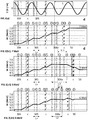
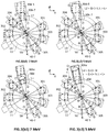
- the adding length (L+) is such that when the electron beam is reintroduced into the resonant cavity, the RF system is synchronized for applying an electric field for accelerating the electron beam along the second radial trajectory between the cavity inlet aperture and the central axis, Zc (cf. Figures 2(a), 2(b1), 2(c1) , 3(a) and 3(b1)-3(d1) , section between positions (2) and (3)).
- the electron beam is injected in the resonant cavity by the electron source (20) through the introduction inlet opening along the mid-plane, Pm. It follows a first radial trajectory in the mid-plane, Pm, said trajectory sequentially crossing:
- an electron beam exiting the resonant cavity through a cavity outlet aperture is deflected by the deflecting magnets of the magnet unit (30i) and reintroduced into the resonant cavity through a first cavity inlet aperture (31w) (which can be the same as or different from the first cavity outlet aperture) along a different radial trajectory, thus forming a first petal of a flower).
- the electron beam can follow such path a number N of times forming N petals centred on the central axis, Zc and comprised in the mid-plane Pm, until it reaches a target energy.
- the electron beam is then extracted out of the resonant cavity through an electron beam outlet (50).
- the magnetic field required in the deflecting chambers must be sufficient for bending the trajectory of an electron beam exiting the resonant chamber along a radial trajectory through a cavity outlet aperture (31w) in an arc of circle of angle greater than 180° to drive it back into the resonant chamber along a second radial trajectory.
- the angle can be equal to 198°.
- the chamber surface must therefore have a length in a radial direction of the order of 65 to 260 mm.
- the magnetic field required for bending an electron beam to such arcs of circle is of the order of between 0.01 T and 1.3 T, preferably 0.02 T to 0.7 T, for example 0.2 or 0.3 T, depending on the desired gyroradius.
- the magnet units may comprise electro-magnets which allow an easy control of the magnitude of the magnetic field created in the magnet unit.
- one or more magnet units preferably N magnet units, may comprise a first and second permanent magnets instead of or additionally to a first and second electromagnets. Permanent magnets and electro-magnets are discussed below.
- a radial trajectory is defined as a rectilinear trajectory comprised in the mid-plane, Pm, and intersecting perpendicularly the central axis, Zc.
- the gist of the present invention is to provide at least one of the N magnet units (30i) as a "vario-magnet unit" (306-5, 306-7, 306v), which is a magnet unit adapted for modifying the corresponding first deflecting trajectory to a second deflecting trajectory of second length (L2) different from and preferably larger than the adding length (L+) (i.e., L2 > L+), thus allowing a variation of the energy, W, of the accelerated electron beam extracted from the outlet (50).
- a variable-magnet unit (306-5, 306-7, 306v
- rhodotrons like in conventional rhodotrons, rhodotrons according to the present invention, provided with N magnet units (301-305), including at least one vario-magnet unit (306-5, 306-7, 306v), can generate (N + 1) accelerations of the electrons of an electron beam (40) before it exits the rhodotron with a given energy (N + 1)*wi.
- the vario-magnet units (306-5, 306-7, 306v) are suitable for varying the deflecting trajectory of the electron beam in the deflecting chamber from the first deflecting trajectory of length, L+, to a second deflecting trajectory of length, L2, different from, preferably higher than, the adding length, L+, of the first deflecting trajectory. This has the effect of changing the synchronization of the penetration into the resonant cavity of the electron beam through the cavity inlet cavity (31w) with respect to the frequency of the RF electric field E.
- the second length (L2) is such that when the electron beam is re-introduced into the resonant cavity, the RF system is synchronized for applying an electric field for decelerating the electron beam along the second radial trajectory, thus reducing the energy W of the electron beam.
- E electric field of same magnitude as, but opposite sign to the electric field met by a second electron after a deflecting trajectory of second length, L2 > L+.
- the gyroradius of a vario-energy unit can be maintained constant independent of the radial distance thereof to the central axis, Zc, by using deflectors (30d) for deflecting the trajectories of the electron beam as follows:
- the rhodotron comprises a single vario-magnet unit (306-5, 306-7, 306v)), which is positioned directly upstream of the outlet (50).
- the extracted electron beam (40-5 to 40-7) has an energy comprised between 5 and 7 MeV.
- vario-magnet unit (306v, 306-5, 306-7) in a rhodotron elegantly solves the problem of extracting along a single path electron beams (40-5 to 40-7) of different energies, W.
- Different types of vario-magnet units can be implemented in the present invention, including discrete vario-magnet dual units (306-5, 306-7) and moving vario-magnet units (306v).
- the vario-magnet unit (306-5, 306,7) comprises two sets of magnets.
- the first and second set of magnets (306.7, 306-5) can be adapted for generating a magnetic field either in a single deflecting chamber (31) common to both sets of magnets, or to a first and second deflecting chambers (31), respectively, the first deflecting chamber being in fluid communication with the second deflecting chamber by one or two windows.
- the two-chamber option of the present invention can be implemented very easily on existing conventional rhodotrons.
- vario-magnet unit configuration permits toggling between two predefined and discrete values of energies, W. For this reason, this embodiment can be referred to as "discrete vario-magnet dual unit.”
- Toggling from the first set (306-7) to the second set of magnets (306-5) can be done very easily by activating and deactivating the first set of magnets (306-7).
- Deactivating the first set of magnets can be easily performed with electro-magnets by feeding or not electrical current. If permanent magnets are used instead, they must be removed far enough from the deflecting chamber to drop the magnetic field at the level of the mid-plane Pm.
- the first set of magnets comprises electro-magnets.
- the sixth vario-magnet unit (306-5, 306-7, 306v) is the last before the outlet (50).
- the vario-magnet unit in Example 3 can therefore vary the energy of the extracted electron beam to values centred on 6 MeV ⁇ 1 MeV.
- the number N of magnets is not necessarily six, the number of non-vario magnet units (301-305) can be different from five, and the number of vario-magnet units can be more than one and is not necessarily located at the last position before the outlet (50). Care should be taken if a vario magnet unit is not at the last position, that the change in synchronization with the RF electric field provoked by a vario-magnet unit is maintained to the following passes including non-vario magnet units. A skilled person can easily design the best arrangement of vario- and non-vario-magnet units to yield the desired energy ranges of extracted electron beams.
- a discrete vario-magnet dual unit affords toggling between two predefined second lengths, L2, only.
- a third magnet unit could be envisaged, but the size of the rhodotron comprising such discrete vario-magnet triple- (or more) units would increase accordingly. If more than two energies (second lengths, L2) are desired, other designs are available, such as a moving vario-magnet unit.
- the at least one vario-magnet units (306v) comprises moving means for discretely or continuously moving radially the at least one vario-unit back and forth along a bisecting direction parallel to a bisector of the angle formed by the first and second radial trajectories at the central axis, Zc.
- the second length, L2 of the deflecting trajectory can be varied according to the radial position of the vario-magnet unit and the desired synchronization with the RF electric field can be set to obtain a desired electron beam energy, W.
- the present embodiment of a moving vario-magnet unit allows the second length, L2, to be varied over more than two predefined values.
- the moving vario-magnet unit can move discretely or continuously along the bisecting direction between two boundary positions.
- the two boundary positions can include:
- the moving vario-magnet unit (306v) can move between the closest and furthest positions either continuously or at discrete positions, to vary the second length, L2, between L+ and (L+) + 1/2 ⁇ , so as to obtain an energy gain at the next crossing of the resonant cavity comprised between wi and -wi.
- wi 1 MeV / pass so that the energy gained (or lost) by the electron beam upon the next pass through the resonant cavity can be varied between - 1 MeV and + 1 MeV.
- the energy of the extracted electron beam can therefore vary in the following manner.
- the energy of the extracted electron beam can thus be set to any value comprised between 5 and 7 MeV in the example illustrated in Figure 3 .
- a continuous moving is advantageous for a higher flexibility on the control of the energy of the extracted electron beam.
- a moving vario-magnet unit (306v) can be configured such that the magnitude of the magnetic field automatically decreases as a function of the radial distance thereof to the central axis (Zc) to accommodate the value of the gyroradius to the distance separating the first and second radial trajectories. This can easily be achieved by controlling the current fed to electro-magnets.
- deflectors (30d) as discussed supra can be used instead.
- the deflectors (30d) orient the trajectories of an electron beam between the cavity outlet / inlet apertures and the vario-magnet unit into straight segments parallel to the bisector of the angle formed by the first and second radial trajectories at the central axis, Zc.
- This embodiment is advantageous as it permits to keep constant the magnetic field generated by the vario-magnet unit regardless of the position of the vario-magnet unit (306v).
- the use of deflectors (30d) allows the vario-magnet unit to comprise permanent magnets, instead of or additionally to electro-magnets.
- the moving means of the moving vario-magnet unit (306v) may comprise a motor for displacing back and forth the the moving vario-magnet unit (306v) along the corresponding bisecting direction.
- a rhodotron comprising N magnet units, of which (N - 1) are non-vario magnet units (301-305) and one only is a vario-magnet unit (306-5, 306-7, 306v) positioned directly upstream of the outlet (50) can extract an electron beam of energy ranging between wi (N ⁇ 1).
- the magnet units in conventional rhodotrons are generally provided with electro-magnets. It has been discussed in EP3319402 that magnet units provided with permanent magnets could be used instead.
- a rhodotron according to the present invention may comprise electro-magnets only, permanent magnets only, or a combination of electro-magnets and permanent magnets.
- permanent magnets have the advantage over electro-magnets of decreasing the energy consumption of the rhodotron since, contrary to electro-magnets, permanent magnets need not be powered. Permanent magnets can be coupled directly against the outer wall of the resonant cavity, whilst the coils of electromagnets must be positioned at a distance of the outer wall. By allowing the magnet units to be directly adjacent to the outer wall, the construction of the rhodotron is greatly simplified and the production cost reduced accordingly.
- EP3319402 proposes to solve this problem, by forming each of the first and second permanent magnets of a magnet unit by arranging a number of discrete magnet elements (32), side by side in an array parallel to the mid-plane, Pm.
- the array is formed by one or more rows of discrete magnet elements.
- An array is disposed on either side of the deflecting chamber with respect to the mid-plane, Pm.
- electro-magnets By contrast, the magnitude of the magnetic field generated by electro-magnets is very easy to control by controlling the electric current fed to the coils of the electro-magnets. They are, however, bulky and need wiring which complexifies the production of the rhodotron. A combination of electro-magnets and permanent magnets can therefore be used to profit of the advantages and avoid the drawbacks of each type of magnets.
- all magnet units comprise permanent magnets, but the ones requiring frequent tuning of the magnetic field. These include, for example,
- the rhodotron can have a modular construct as illustrated in the exploded view of Figure 5(a) .
- Each of the first and second half shells forming the resonant cavity comprises a cylindrical outer wall, a bottom lid (11b, 12b), and a central pillar (15p) jutting out of the bottom lid.
- a central chamber (15c) can be sandwiched between the central pillars of the first and second half shells.
- a central ring element (13) is sandwiched between the first and second half-shells.
- the central ring element has a first and second main surfaces separated from one another by a thickness thereof.
- a portion of the central ring element extends radially beyond an outer surface of the outer wall of both first and second half shells, forming a flange extending radially outwards.
- the magnet units (30i) can be mounted on and fitted onto said flange. The fit between the magnet units and the flange preferably affords some play for finely aligning the magnet units with the mid-plane, Pm, and the trajectory of the electron beam.
- the deflecting chambers (31) of the magnet units can be formed by a hollowed cavity in the thickness of the central ring element, with the cavity outlet / inlet apertures (31w) being formed at the inner edge of the central ring element, facing the centre of the central ring element and the central axis, Zc.
- the hollowed cavity can be closed by a lid (13p).
- several deflecting chambers, more preferably all the deflecting chambers of the rhodotron are formed by individual hollowed cavities in the thickness of the central ring element, with the corresponding cavity outlet / inlet apertures being formed in the inner edge of the central ring element, facing the central axis, Zc. This construction reduces substantially the production costs of rhodotrons compared to conventional designs for the following reasons.
Landscapes
- Physics & Mathematics (AREA)
- Engineering & Computer Science (AREA)
- Spectroscopy & Molecular Physics (AREA)
- Plasma & Fusion (AREA)
- General Engineering & Computer Science (AREA)
- High Energy & Nuclear Physics (AREA)
- Optics & Photonics (AREA)
- Particle Accelerators (AREA)
Priority Applications (4)
| Application Number | Priority Date | Filing Date | Title |
|---|---|---|---|
| EP18208924.3A EP3661335B1 (en) | 2018-11-28 | 2018-11-28 | Vario-energy electron accelerator |
| CN201911147902.7A CN111246654B (zh) | 2018-11-28 | 2019-11-21 | 可变能量的电子加速器 |
| JP2019212384A JP7076423B2 (ja) | 2018-11-28 | 2019-11-25 | バリオエネルギー電子加速器 |
| US16/698,149 US10743401B2 (en) | 2018-11-28 | 2019-11-27 | Vario-energy electron accelerator |
Applications Claiming Priority (1)
| Application Number | Priority Date | Filing Date | Title |
|---|---|---|---|
| EP18208924.3A EP3661335B1 (en) | 2018-11-28 | 2018-11-28 | Vario-energy electron accelerator |
Publications (2)
| Publication Number | Publication Date |
|---|---|
| EP3661335A1 EP3661335A1 (en) | 2020-06-03 |
| EP3661335B1 true EP3661335B1 (en) | 2021-06-30 |
Family
ID=64556790
Family Applications (1)
| Application Number | Title | Priority Date | Filing Date |
|---|---|---|---|
| EP18208924.3A Active EP3661335B1 (en) | 2018-11-28 | 2018-11-28 | Vario-energy electron accelerator |
Country Status (4)
| Country | Link |
|---|---|
| US (1) | US10743401B2 (enExample) |
| EP (1) | EP3661335B1 (enExample) |
| JP (1) | JP7076423B2 (enExample) |
| CN (1) | CN111246654B (enExample) |
Families Citing this family (7)
| Publication number | Priority date | Publication date | Assignee | Title |
|---|---|---|---|---|
| EP3661335B1 (en) * | 2018-11-28 | 2021-06-30 | Ion Beam Applications | Vario-energy electron accelerator |
| CN114375540B (zh) * | 2019-07-09 | 2025-03-11 | 万睿视影像有限公司 | 电子枪驱动器 |
| EP3876679B1 (en) * | 2020-03-06 | 2022-07-20 | Ion Beam Applications | Synchrocyclotron for extracting beams of various energies and related method |
| CN112888139A (zh) * | 2020-12-29 | 2021-06-01 | 中国科学院近代物理研究所 | 一种同轴腔加速器出口电子束能量调节系统及方法 |
| CN112888138B (zh) * | 2020-12-30 | 2024-02-06 | 中国科学院近代物理研究所 | 一种产生高品质电子束的往返式同轴腔电子加速器 |
| CN113933761B (zh) * | 2021-09-09 | 2022-09-27 | 中国地质大学(武汉) | 基于电容加载同轴谐振腔的ovh磁传感器腔体 |
| CN118510141B (zh) * | 2024-07-22 | 2024-11-19 | 苏州益腾电子科技有限公司 | 一种微焦点x射线的产生装置 |
Family Cites Families (14)
| Publication number | Priority date | Publication date | Assignee | Title |
|---|---|---|---|---|
| FR2616032B1 (fr) | 1987-05-26 | 1989-08-04 | Commissariat Energie Atomique | Accelerateur d'electrons a cavite coaxiale |
| JP2002141200A (ja) * | 2000-10-31 | 2002-05-17 | Toshiba Corp | 電子線装置 |
| JP6277135B2 (ja) * | 2012-02-03 | 2018-02-07 | イオン・ビーム・アプリケーションズ・エス・アー | 等時性超伝導小型サイクロトロン用磁性構造体 |
| EP2804451B1 (en) * | 2013-05-17 | 2016-01-06 | Ion Beam Applications S.A. | Electron accelerator having a coaxial cavity |
| CA2832816C (en) * | 2013-11-12 | 2020-06-02 | Mikhail V. Gavich | Accelerator - generator |
| EP3102009A1 (en) * | 2015-06-04 | 2016-12-07 | Ion Beam Applications S.A. | Multiple energy electron accelerator |
| EP3178522B1 (en) * | 2015-12-11 | 2018-02-14 | Ion Beam Applications S.A. | Particle therapy system with parallel control of energy variation and beam position variation |
| CN105578703B (zh) * | 2016-03-03 | 2018-06-22 | 北京鑫智能技术股份有限公司 | 一口出多档能量电子束的花瓣型加速器 |
| EP3319402B1 (en) | 2016-11-07 | 2021-03-03 | Ion Beam Applications S.A. | Compact electron accelerator comprising permanent magnets |
| EP3319403B1 (en) * | 2016-11-07 | 2022-01-05 | Ion Beam Applications S.A. | Compact electron accelerator comprising first and second half shells |
| CN207638964U (zh) * | 2017-12-13 | 2018-07-20 | 北京鑫智能技术股份有限公司 | 利用永久磁铁引导电子多次加速的花瓣型加速器 |
| CN207802493U (zh) * | 2018-02-11 | 2018-08-31 | 北京鑫智能技术股份有限公司 | 花瓣型加速器及其c型回转电磁铁 |
| CN108770181A (zh) * | 2018-05-24 | 2018-11-06 | 新瑞阳光粒子医疗装备(无锡)有限公司 | 同步加速器、粒子束加速方法、装置、设备及存储介质 |
| EP3661335B1 (en) * | 2018-11-28 | 2021-06-30 | Ion Beam Applications | Vario-energy electron accelerator |
-
2018
- 2018-11-28 EP EP18208924.3A patent/EP3661335B1/en active Active
-
2019
- 2019-11-21 CN CN201911147902.7A patent/CN111246654B/zh active Active
- 2019-11-25 JP JP2019212384A patent/JP7076423B2/ja active Active
- 2019-11-27 US US16/698,149 patent/US10743401B2/en active Active
Also Published As
| Publication number | Publication date |
|---|---|
| JP7076423B2 (ja) | 2022-05-27 |
| CN111246654B (zh) | 2022-04-08 |
| US10743401B2 (en) | 2020-08-11 |
| EP3661335A1 (en) | 2020-06-03 |
| CN111246654A (zh) | 2020-06-05 |
| US20200170099A1 (en) | 2020-05-28 |
| JP2020087932A (ja) | 2020-06-04 |
Similar Documents
| Publication | Publication Date | Title |
|---|---|---|
| EP3661335B1 (en) | Vario-energy electron accelerator | |
| Khiari et al. | Acceleration of polarized protons to 22 GeV/c and the measurement of spin-spin effects in p↑+ p↑→ p+p | |
| GB2377547A (en) | Particle accelerator formed from a series of monolithic sections | |
| EP0037051B1 (de) | Linearbeschleuniger für geladene Teilchen | |
| US5004926A (en) | Device for the irradiation of a product on both faces | |
| JP2596292B2 (ja) | 円形加速器及びその運転方法並びに医療システム | |
| EP3319403B1 (en) | Compact electron accelerator comprising first and second half shells | |
| CN107079577A (zh) | 高频紧凑型低能量直线加速器设计 | |
| KR20140145119A (ko) | 레이저 구동 이온 빔의 레이저 활성화 자기장 조정 | |
| JP3736343B2 (ja) | 直流電子ビーム加速装置およびその直流電子ビーム加速方法 | |
| US10271418B2 (en) | Compact electron accelerator comprising permanent magnets | |
| JP2020087932A5 (enExample) | ||
| GB2566118A (en) | Linear accelerating structure for protons | |
| WO2014184306A1 (en) | Electron accelerator having a coaxial cavity | |
| CN103314647A (zh) | 以在两个能级之间可调的脉冲产生脉冲韧致辐射的方法和设备 | |
| ES2641769T3 (es) | Dispositivo de hiperfrecuencias de aceleración de electrones | |
| US5039910A (en) | Standing-wave accelerating structure with different diameter bores in bunching and regular cavity sections | |
| US6486482B1 (en) | Irradiation equipment | |
| JP2013506942A (ja) | 加速器、及び加速器を作動させる方法 | |
| CN103582277A (zh) | MeV-电子源 | |
| EP3102009A1 (en) | Multiple energy electron accelerator | |
| Auslender et al. | Electron accelerator for energy up to 5.0 MeV and beam power up to 50 kW | |
| WO2021192348A1 (ja) | 加速器および粒子線治療装置 | |
| JPH05145199A (ja) | 自由電子レーザ | |
| WO2015185762A1 (en) | Multiple energy single electron beam generator |
Legal Events
| Date | Code | Title | Description |
|---|---|---|---|
| PUAI | Public reference made under article 153(3) epc to a published international application that has entered the european phase |
Free format text: ORIGINAL CODE: 0009012 |
|
| STAA | Information on the status of an ep patent application or granted ep patent |
Free format text: STATUS: REQUEST FOR EXAMINATION WAS MADE |
|
| 17P | Request for examination filed |
Effective date: 20191029 |
|
| AK | Designated contracting states |
Kind code of ref document: A1 Designated state(s): AL AT BE BG CH CY CZ DE DK EE ES FI FR GB GR HR HU IE IS IT LI LT LU LV MC MK MT NL NO PL PT RO RS SE SI SK SM TR |
|
| AX | Request for extension of the european patent |
Extension state: BA ME |
|
| GRAP | Despatch of communication of intention to grant a patent |
Free format text: ORIGINAL CODE: EPIDOSNIGR1 |
|
| STAA | Information on the status of an ep patent application or granted ep patent |
Free format text: STATUS: GRANT OF PATENT IS INTENDED |
|
| INTG | Intention to grant announced |
Effective date: 20210127 |
|
| GRAS | Grant fee paid |
Free format text: ORIGINAL CODE: EPIDOSNIGR3 |
|
| GRAA | (expected) grant |
Free format text: ORIGINAL CODE: 0009210 |
|
| STAA | Information on the status of an ep patent application or granted ep patent |
Free format text: STATUS: THE PATENT HAS BEEN GRANTED |
|
| AK | Designated contracting states |
Kind code of ref document: B1 Designated state(s): AL AT BE BG CH CY CZ DE DK EE ES FI FR GB GR HR HU IE IS IT LI LT LU LV MC MK MT NL NO PL PT RO RS SE SI SK SM TR |
|
| REG | Reference to a national code |
Ref country code: CH Ref legal event code: EP |
|
| REG | Reference to a national code |
Ref country code: AT Ref legal event code: REF Ref document number: 1407622 Country of ref document: AT Kind code of ref document: T Effective date: 20210715 |
|
| REG | Reference to a national code |
Ref country code: DE Ref legal event code: R096 Ref document number: 602018019289 Country of ref document: DE |
|
| REG | Reference to a national code |
Ref country code: IE Ref legal event code: FG4D |
|
| REG | Reference to a national code |
Ref country code: LT Ref legal event code: MG9D |
|
| PG25 | Lapsed in a contracting state [announced via postgrant information from national office to epo] |
Ref country code: FI Free format text: LAPSE BECAUSE OF FAILURE TO SUBMIT A TRANSLATION OF THE DESCRIPTION OR TO PAY THE FEE WITHIN THE PRESCRIBED TIME-LIMIT Effective date: 20210630 Ref country code: HR Free format text: LAPSE BECAUSE OF FAILURE TO SUBMIT A TRANSLATION OF THE DESCRIPTION OR TO PAY THE FEE WITHIN THE PRESCRIBED TIME-LIMIT Effective date: 20210630 Ref country code: BG Free format text: LAPSE BECAUSE OF FAILURE TO SUBMIT A TRANSLATION OF THE DESCRIPTION OR TO PAY THE FEE WITHIN THE PRESCRIBED TIME-LIMIT Effective date: 20210930 |
|
| REG | Reference to a national code |
Ref country code: AT Ref legal event code: MK05 Ref document number: 1407622 Country of ref document: AT Kind code of ref document: T Effective date: 20210630 |
|
| PG25 | Lapsed in a contracting state [announced via postgrant information from national office to epo] |
Ref country code: GR Free format text: LAPSE BECAUSE OF FAILURE TO SUBMIT A TRANSLATION OF THE DESCRIPTION OR TO PAY THE FEE WITHIN THE PRESCRIBED TIME-LIMIT Effective date: 20211001 Ref country code: NO Free format text: LAPSE BECAUSE OF FAILURE TO SUBMIT A TRANSLATION OF THE DESCRIPTION OR TO PAY THE FEE WITHIN THE PRESCRIBED TIME-LIMIT Effective date: 20210930 Ref country code: LV Free format text: LAPSE BECAUSE OF FAILURE TO SUBMIT A TRANSLATION OF THE DESCRIPTION OR TO PAY THE FEE WITHIN THE PRESCRIBED TIME-LIMIT Effective date: 20210630 Ref country code: RS Free format text: LAPSE BECAUSE OF FAILURE TO SUBMIT A TRANSLATION OF THE DESCRIPTION OR TO PAY THE FEE WITHIN THE PRESCRIBED TIME-LIMIT Effective date: 20210630 Ref country code: SE Free format text: LAPSE BECAUSE OF FAILURE TO SUBMIT A TRANSLATION OF THE DESCRIPTION OR TO PAY THE FEE WITHIN THE PRESCRIBED TIME-LIMIT Effective date: 20210630 |
|
| REG | Reference to a national code |
Ref country code: NL Ref legal event code: FP |
|
| PG25 | Lapsed in a contracting state [announced via postgrant information from national office to epo] |
Ref country code: SK Free format text: LAPSE BECAUSE OF FAILURE TO SUBMIT A TRANSLATION OF THE DESCRIPTION OR TO PAY THE FEE WITHIN THE PRESCRIBED TIME-LIMIT Effective date: 20210630 Ref country code: SM Free format text: LAPSE BECAUSE OF FAILURE TO SUBMIT A TRANSLATION OF THE DESCRIPTION OR TO PAY THE FEE WITHIN THE PRESCRIBED TIME-LIMIT Effective date: 20210630 Ref country code: EE Free format text: LAPSE BECAUSE OF FAILURE TO SUBMIT A TRANSLATION OF THE DESCRIPTION OR TO PAY THE FEE WITHIN THE PRESCRIBED TIME-LIMIT Effective date: 20210630 Ref country code: ES Free format text: LAPSE BECAUSE OF FAILURE TO SUBMIT A TRANSLATION OF THE DESCRIPTION OR TO PAY THE FEE WITHIN THE PRESCRIBED TIME-LIMIT Effective date: 20210630 Ref country code: CZ Free format text: LAPSE BECAUSE OF FAILURE TO SUBMIT A TRANSLATION OF THE DESCRIPTION OR TO PAY THE FEE WITHIN THE PRESCRIBED TIME-LIMIT Effective date: 20210630 Ref country code: AT Free format text: LAPSE BECAUSE OF FAILURE TO SUBMIT A TRANSLATION OF THE DESCRIPTION OR TO PAY THE FEE WITHIN THE PRESCRIBED TIME-LIMIT Effective date: 20210630 Ref country code: RO Free format text: LAPSE BECAUSE OF FAILURE TO SUBMIT A TRANSLATION OF THE DESCRIPTION OR TO PAY THE FEE WITHIN THE PRESCRIBED TIME-LIMIT Effective date: 20210630 Ref country code: PT Free format text: LAPSE BECAUSE OF FAILURE TO SUBMIT A TRANSLATION OF THE DESCRIPTION OR TO PAY THE FEE WITHIN THE PRESCRIBED TIME-LIMIT Effective date: 20211102 |
|
| PG25 | Lapsed in a contracting state [announced via postgrant information from national office to epo] |
Ref country code: PL Free format text: LAPSE BECAUSE OF FAILURE TO SUBMIT A TRANSLATION OF THE DESCRIPTION OR TO PAY THE FEE WITHIN THE PRESCRIBED TIME-LIMIT Effective date: 20210630 |
|
| REG | Reference to a national code |
Ref country code: DE Ref legal event code: R097 Ref document number: 602018019289 Country of ref document: DE |
|
| PG25 | Lapsed in a contracting state [announced via postgrant information from national office to epo] |
Ref country code: DK Free format text: LAPSE BECAUSE OF FAILURE TO SUBMIT A TRANSLATION OF THE DESCRIPTION OR TO PAY THE FEE WITHIN THE PRESCRIBED TIME-LIMIT Effective date: 20210630 |
|
| PLBE | No opposition filed within time limit |
Free format text: ORIGINAL CODE: 0009261 |
|
| STAA | Information on the status of an ep patent application or granted ep patent |
Free format text: STATUS: NO OPPOSITION FILED WITHIN TIME LIMIT |
|
| PG25 | Lapsed in a contracting state [announced via postgrant information from national office to epo] |
Ref country code: AL Free format text: LAPSE BECAUSE OF FAILURE TO SUBMIT A TRANSLATION OF THE DESCRIPTION OR TO PAY THE FEE WITHIN THE PRESCRIBED TIME-LIMIT Effective date: 20210630 |
|
| 26N | No opposition filed |
Effective date: 20220331 |
|
| PG25 | Lapsed in a contracting state [announced via postgrant information from national office to epo] |
Ref country code: MC Free format text: LAPSE BECAUSE OF FAILURE TO SUBMIT A TRANSLATION OF THE DESCRIPTION OR TO PAY THE FEE WITHIN THE PRESCRIBED TIME-LIMIT Effective date: 20210630 |
|
| PG25 | Lapsed in a contracting state [announced via postgrant information from national office to epo] |
Ref country code: LU Free format text: LAPSE BECAUSE OF NON-PAYMENT OF DUE FEES Effective date: 20211128 Ref country code: IT Free format text: LAPSE BECAUSE OF FAILURE TO SUBMIT A TRANSLATION OF THE DESCRIPTION OR TO PAY THE FEE WITHIN THE PRESCRIBED TIME-LIMIT Effective date: 20210630 |
|
| PG25 | Lapsed in a contracting state [announced via postgrant information from national office to epo] |
Ref country code: IE Free format text: LAPSE BECAUSE OF NON-PAYMENT OF DUE FEES Effective date: 20211128 |
|
| PG25 | Lapsed in a contracting state [announced via postgrant information from national office to epo] |
Ref country code: LT Free format text: LAPSE BECAUSE OF FAILURE TO SUBMIT A TRANSLATION OF THE DESCRIPTION OR TO PAY THE FEE WITHIN THE PRESCRIBED TIME-LIMIT Effective date: 20210630 |
|
| P01 | Opt-out of the competence of the unified patent court (upc) registered |
Effective date: 20230504 |
|
| PG25 | Lapsed in a contracting state [announced via postgrant information from national office to epo] |
Ref country code: CY Free format text: LAPSE BECAUSE OF FAILURE TO SUBMIT A TRANSLATION OF THE DESCRIPTION OR TO PAY THE FEE WITHIN THE PRESCRIBED TIME-LIMIT Effective date: 20210630 |
|
| PG25 | Lapsed in a contracting state [announced via postgrant information from national office to epo] |
Ref country code: HU Free format text: LAPSE BECAUSE OF FAILURE TO SUBMIT A TRANSLATION OF THE DESCRIPTION OR TO PAY THE FEE WITHIN THE PRESCRIBED TIME-LIMIT; INVALID AB INITIO Effective date: 20181128 |
|
| PG25 | Lapsed in a contracting state [announced via postgrant information from national office to epo] |
Ref country code: MK Free format text: LAPSE BECAUSE OF FAILURE TO SUBMIT A TRANSLATION OF THE DESCRIPTION OR TO PAY THE FEE WITHIN THE PRESCRIBED TIME-LIMIT Effective date: 20210630 |
|
| PG25 | Lapsed in a contracting state [announced via postgrant information from national office to epo] |
Ref country code: TR Free format text: LAPSE BECAUSE OF FAILURE TO SUBMIT A TRANSLATION OF THE DESCRIPTION OR TO PAY THE FEE WITHIN THE PRESCRIBED TIME-LIMIT Effective date: 20210630 |
|
| PG25 | Lapsed in a contracting state [announced via postgrant information from national office to epo] |
Ref country code: MT Free format text: LAPSE BECAUSE OF FAILURE TO SUBMIT A TRANSLATION OF THE DESCRIPTION OR TO PAY THE FEE WITHIN THE PRESCRIBED TIME-LIMIT Effective date: 20210630 |
|
| PGFP | Annual fee paid to national office [announced via postgrant information from national office to epo] |
Ref country code: NL Payment date: 20241126 Year of fee payment: 7 |
|
| PGFP | Annual fee paid to national office [announced via postgrant information from national office to epo] |
Ref country code: DE Payment date: 20241127 Year of fee payment: 7 |
|
| PGFP | Annual fee paid to national office [announced via postgrant information from national office to epo] |
Ref country code: BE Payment date: 20241127 Year of fee payment: 7 |
|
| PGFP | Annual fee paid to national office [announced via postgrant information from national office to epo] |
Ref country code: GB Payment date: 20241127 Year of fee payment: 7 |
|
| PGFP | Annual fee paid to national office [announced via postgrant information from national office to epo] |
Ref country code: FR Payment date: 20241128 Year of fee payment: 7 |
|
| PGFP | Annual fee paid to national office [announced via postgrant information from national office to epo] |
Ref country code: CH Payment date: 20241201 Year of fee payment: 7 |
|
| REG | Reference to a national code |
Ref country code: CH Ref legal event code: U11 Free format text: ST27 STATUS EVENT CODE: U-0-0-U10-U11 (AS PROVIDED BY THE NATIONAL OFFICE) Effective date: 20251201 |