EP3661252B1 - Information generating method and device, signal transmitting method and device - Google Patents
Information generating method and device, signal transmitting method and device Download PDFInfo
- Publication number
- EP3661252B1 EP3661252B1 EP17920696.6A EP17920696A EP3661252B1 EP 3661252 B1 EP3661252 B1 EP 3661252B1 EP 17920696 A EP17920696 A EP 17920696A EP 3661252 B1 EP3661252 B1 EP 3661252B1
- Authority
- EP
- European Patent Office
- Prior art keywords
- beam signal
- cell
- base station
- identification information
- receiving
- Prior art date
- Legal status (The legal status is an assumption and is not a legal conclusion. Google has not performed a legal analysis and makes no representation as to the accuracy of the status listed.)
- Active
Links
- 238000000034 method Methods 0.000 title claims description 52
- 238000004891 communication Methods 0.000 claims description 18
- 230000004044 response Effects 0.000 claims description 11
- 238000004590 computer program Methods 0.000 claims description 6
- 238000012545 processing Methods 0.000 description 13
- 238000010586 diagram Methods 0.000 description 12
- 230000008667 sleep stage Effects 0.000 description 6
- 238000005259 measurement Methods 0.000 description 4
- 230000003287 optical effect Effects 0.000 description 4
- 230000005855 radiation Effects 0.000 description 4
- 230000005236 sound signal Effects 0.000 description 4
- 230000001360 synchronised effect Effects 0.000 description 3
- 230000001133 acceleration Effects 0.000 description 2
- 230000005540 biological transmission Effects 0.000 description 2
- 238000005516 engineering process Methods 0.000 description 2
- 230000003993 interaction Effects 0.000 description 2
- 238000007726 management method Methods 0.000 description 2
- 230000002093 peripheral effect Effects 0.000 description 2
- 230000006978 adaptation Effects 0.000 description 1
- 230000009286 beneficial effect Effects 0.000 description 1
- 230000001413 cellular effect Effects 0.000 description 1
- 230000000295 complement effect Effects 0.000 description 1
- 238000010276 construction Methods 0.000 description 1
- 238000013500 data storage Methods 0.000 description 1
- 230000001419 dependent effect Effects 0.000 description 1
- 230000000694 effects Effects 0.000 description 1
- 230000005611 electricity Effects 0.000 description 1
- 238000003384 imaging method Methods 0.000 description 1
- 239000004973 liquid crystal related substance Substances 0.000 description 1
- 238000012986 modification Methods 0.000 description 1
- 230000004048 modification Effects 0.000 description 1
- 239000004065 semiconductor Substances 0.000 description 1
- 230000007958 sleep Effects 0.000 description 1
- 230000003068 static effect Effects 0.000 description 1
Images


Classifications
-
- H—ELECTRICITY
- H04—ELECTRIC COMMUNICATION TECHNIQUE
- H04W—WIRELESS COMMUNICATION NETWORKS
- H04W36/00—Hand-off or reselection arrangements
- H04W36/0005—Control or signalling for completing the hand-off
- H04W36/0055—Transmission or use of information for re-establishing the radio link
- H04W36/0061—Transmission or use of information for re-establishing the radio link of neighbour cell information
-
- H—ELECTRICITY
- H04—ELECTRIC COMMUNICATION TECHNIQUE
- H04W—WIRELESS COMMUNICATION NETWORKS
- H04W36/00—Hand-off or reselection arrangements
- H04W36/08—Reselecting an access point
- H04W36/085—Reselecting an access point involving beams of access points
-
- H—ELECTRICITY
- H04—ELECTRIC COMMUNICATION TECHNIQUE
- H04W—WIRELESS COMMUNICATION NETWORKS
- H04W36/00—Hand-off or reselection arrangements
- H04W36/24—Reselection being triggered by specific parameters
- H04W36/26—Reselection being triggered by specific parameters by agreed or negotiated communication parameters
-
- H—ELECTRICITY
- H04—ELECTRIC COMMUNICATION TECHNIQUE
- H04W—WIRELESS COMMUNICATION NETWORKS
- H04W36/00—Hand-off or reselection arrangements
- H04W36/24—Reselection being triggered by specific parameters
- H04W36/32—Reselection being triggered by specific parameters by location or mobility data, e.g. speed data
- H04W36/324—Reselection being triggered by specific parameters by location or mobility data, e.g. speed data by mobility data, e.g. speed data
-
- H—ELECTRICITY
- H04—ELECTRIC COMMUNICATION TECHNIQUE
- H04W—WIRELESS COMMUNICATION NETWORKS
- H04W48/00—Access restriction; Network selection; Access point selection
- H04W48/08—Access restriction or access information delivery, e.g. discovery data delivery
- H04W48/12—Access restriction or access information delivery, e.g. discovery data delivery using downlink control channel
-
- H—ELECTRICITY
- H04—ELECTRIC COMMUNICATION TECHNIQUE
- H04W—WIRELESS COMMUNICATION NETWORKS
- H04W48/00—Access restriction; Network selection; Access point selection
- H04W48/16—Discovering, processing access restriction or access information
-
- H—ELECTRICITY
- H04—ELECTRIC COMMUNICATION TECHNIQUE
- H04W—WIRELESS COMMUNICATION NETWORKS
- H04W48/00—Access restriction; Network selection; Access point selection
- H04W48/20—Selecting an access point
Definitions
- Embodiments herein relates to the field of communications, and in particular to a method for generating information, a method for sending a signal, User Equipment (UE), a base station, and computer-readable storage media.
- UE User Equipment
- a synchronized block may be transmitted mainly by beam scan, and a synchronized block may bear a synchronization signal and a Physical Broadcast Channel (PBCH).
- 5G 5th-Generation
- 3GPP 3rd Generation Partnership Project
- the UE may receive a beam signal to acquire a synchronized block in the beam signal.
- the UE may have to receive not only a beam signal from a cell where the UE camps, but also a beam signal from a neighbor cell.
- the UE may also have to determine both a Signal-to-Noise Ratio (SNR) of the beam signal from the cell where the UE camps and an SNR of the beam signal from the neighbor cell.
- the UE may have to upload each SNR and an identification of a beam signal corresponding to the each SNR to a base station managing the cell.
- SNR Signal-to-Noise Ratio
- UE may have to parse information borne on a PBCH in the beam signal.
- the parse may be time consuming, which may prevent UE from being handed over to a target cell in time.
- KR 2016 0143509 A discloses selecting partial directional beams as a measurement object based on a moving trajectory of a terminal, among a plurality of directional beams which at least one neighbor cell transmits; transmitting a beam candidate group including the partial directional beams to the terminal; and receiving neighbor cell measurement information which the terminal measures through the beam candidate group, from the terminal.
- EP 2 928 234 A1 discloses receiving first radio resource information for a transmission of first reference signals via a first radiation beam (BM1-BS1) being directed towards a first direction by at least one neighboring base station (BS1) of a serving base station (BS2) of the mobile station (MS) and at least second radio resource information for a transmission of at least second reference signals via at least one second radiation beam (BM2-BS1, ..., BM5-BS1) being directed towards at least one second direction by the at least one neighboring base station (BS1); receiving the first reference signals based on the first radio resource information, receiving the at least second reference signals based on the at least second radio resource information, determining first quality information of the first radiation beam (BM1-BS1) based on the received first reference signals and at least second quality information of the at least second radiation beam (BM2-BS1, ..., BM5-BS1) based on the received at least second reference signals, and transmitting at least one of the first quality information and the at least second quality information to the serving base station (BS2).
- NEC "Measurement and Reporting for Inter-Cell Mobility in NR", 3GPP DRAFT; R2-168402, discloses measurement and reporting for inter-cell mobility in NR, reporting quality of beams of a neighbor cell.
- embodiments herein provide a method for generating information, a method for sending a signal, UE, a base station, and computer-readable storage media.
- a method for generating information applies to User Equipment (UE).
- the method includes:
- the UE is in a connected state.
- the UE may be in an idle state, which is not encompassed by the claims.
- the method may further include: in response to the UE being in the idle state (which is not encompassed by the claims), while receiving the first beam signal, receiving another beam signal from the first cell that is spaced from the first beam signal by a number of beams less than a preset number.
- the generating cell handover information according to the at least one second beam signal and the first beam signal may include: generating the cell handover information according to the at least one second beam signal, the first beam signal, and the another beam signal.
- the first beam signal may further include identification information that identifies the second cell.
- the method may further include:
- the second beam signal from the second cell in the scene of high mobility may include a perpendicular beam signal perpendicular to a direction in which the UE moves, and a parallel beam signal parallel to the direction in which the UE moves.
- the accessing the second cell according to the cell handover information may include: establishing a communication connection with a base station that manages the second cell, and receiving the parallel beam signal.
- a method for sending a signal applies to a base station.
- the method includes:
- Receiving the second identification information may include: receiving the second beam signal, the second beam signal carrying the second identification information.
- Receiving the second identification information may include: receiving the second identification information through an interface between the base station and the neighbor base station.
- a device for generating information applies to User Equipment (UE).
- the device includes a receiving portion and a generating portion.
- the receiving portion is adapted to: receiving a first beam signal from a first cell where the UE camps, the first beam signal including second identification information that identifies a second beam signal, the second beam signal being at least one beam signal from a second cell neighboring the first cell, the at least one second beam signal neighboring the first beam signal; determining the at least one second beam signal according to the second identification information; receiving the at least one second beam signal.
- the generating portion is adapted to: generating cell handover information according to the at least one second beam signal and the first beam signal.
- the UE is in a connected state.
- the UE may be in an idle state, which is not encompassed by the claims.
- the receiving portion may be further adapted to, in response to the UE being in the idle state (which is not encompassed by the claims), while receiving the first beam signal, receiving another beam signal from the first cell that is spaced from the first beam signal by a number of beams less than a preset number.
- the generating portion may be adapted to generating the cell handover information according to the at least one second beam signal, the first beam signal, and the another beam signal.
- the first beam signal may further include identification information that identifies the second cell.
- the device may further include a cell determining portion and a handover portion.
- the cell determining portion may be adapted to, in response to the UE being in the connected state, determining whether the second cell is in a scene of high mobility according to the identification information that identifies the second cell.
- the handover portion may be adapted to, in response to the second cell being in a scene of high mobility, accessing the second cell according to the cell handover information.
- the second beam signal from the second cell in the scene of high mobility may include a perpendicular beam signal perpendicular to a direction in which the UE moves, and a parallel beam signal parallel to the direction in which the UE moves.
- the handover portion may be adapted to: establishing a communication connection with a base station that manages the second cell, and receiving the parallel beam signal.
- a device for sending a signal applies to a base station.
- the device includes an equipment determining portion, an information receiving portion, and an information sending portion.
- the equipment determining portion is adapted to determining User Equipment (UE) that receives a first beam signal sent by the base station.
- UE User Equipment
- the information receiving portion is adapted to receiving second identification information in a beam signal sent by a neighbor base station of the base station.
- the second identification information identifies at least one second beam signal sent by the neighbor base station.
- the at least one second beam signal neighbors the first beam signal.
- the information sending portion is adapted to sending the second identification information to the UE.
- the information receiving portion may be adapted to receiving the second beam signal.
- the second beam signal may carry the second identification information.
- the information receiving portion may be adapted to receiving the second identification information through an interface between the base station and the neighbor base station.
- UE User Equipment
- UE includes a processor and memory.
- the memory is adapted to storing an instruction executable by the processor.
- the processor is adapted to:
- a base station includes a processor and memory.
- the memory is adapted to storing an instruction executable by the processor.
- the processor is adapted to:
- a computer-readable storage medium has stored thereon a computer program that, when executed by a processor, causes the processor to perform:
- a computer-readable storage medium has stored thereon a computer program that, when executed by a processor, causes the processor to perform:
- the UE by transmitting identification information that identifies at least one second beam signal to UE, on one hand, the UE is allowed to determine the identification information that identifies the second beam signal to determine and receive the second beam signal without having to parse information borne on a PBCH of the second beam signal.
- the UE may compute only the SNR of the second beam signal without having to compute the SNR of each second beam signal from the second cell. Both may reduce time consumed in a handover and speed up the handover of the UE.
- FIG. 1 is a flowchart of a method for generating information according to an exemplary embodiment.
- the method for generating information applies to UE such as a mobile phone, a tablet computer, etc.
- the UE may receive a beam signal from a cell formed by a base station such as a 5G base station.
- the method for generating information includes at least one option as follows.
- a first beam signal from a first cell where the UE camps is received.
- the first beam signal includes second identification information that identifies a second beam signal.
- the second beam signal is at least one beam signal from a second cell neighboring the first cell. The at least one second beam signal neighbors the first beam signal.
- the at least one second beam signal is determined according to the second identification information.
- the at least one second beam signal is received.
- cell handover information is generated according to the at least one second beam signal and the first beam signal.
- the cell handover information thus generated may include an SNR of the first beam signal.
- the cell handover information may include an SNR of each of the at least one second beam signal.
- the cell handover information may be transmitted to a base station corresponding to or managing the first cell and/or the second cell.
- the base station may determine whether cell handover is required for the UE.
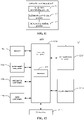
- FIG. 2 is a diagram of a beam signal relation according to an exemplary embodiment.
- the first cell and the second cell may be formed by 5G base stations. Multiple cells may form a cellular network. There may be six second cells 2 neighboring the first cell 1.
- a first base station corresponding to/managing/forming the first cell may transmit multiple first beam signals.
- the first base station may store second identification information that identifies a second beam signal neighboring a respective first beam signal. For example, second beam signals 21, 22, and 23 from a second cell 2 may neighbor a first beam signal 11 from the first cell.
- a number and range of beam signals neighboring a beam signal may be set as needed.
- the second beam signal 22 from the second cell that is opposite to the first beam signal 11, and second beam signals 21 and 23 beside the second beam signal 22, may be set as second beam signals neighboring the first beam signal 11.
- only the second beam signal 22 may be set as the second beam signal neighboring the first beam signal 11.
- a second beam signal corresponding to a first beam signal 12 from the first cell may include a second beam signal 23 from the second cell 2 and a second beam signal 21' from a second cell 2'. Accordingly, the second beam signals 23 and 21' may be set as second beam signals neighboring the first beam signal 12.
- second identification information that respectively identifies second beam signals 21, 22, and 23 may be acquired.
- the second beam signals 21, 22, and 23 neighbor (namely, are close to) the first beam signal 11. Therefore, after the UE has been handed over to the second cell 2 from the first beam signal 11, strength of second beam signals 21, 22, and 23 received by the UE may be greater than strength of another beam in the second cell 2. This may ensure a good communication result regardless of which one of the three second beam signals is received by the UE after the handover.
- the UE by transmitting identification information that identifies at least one second beam signal to UE, on one hand, the UE is allowed to determine the identification information that identifies the second beam signal to determine and receive the second beam signal without having to parse information borne on a PBCH of the second beam signal.
- the UE may compute only the SNR of the second beam signal without having to compute the SNR of each second beam signal from the second cell. Both may reduce time consumed in a handover and speed up the handover of the UE.
- the UE is in a connected state.
- the UE may be in an idle state, which is not encompassed by the claims.
- FIG. 3 is a flowchart of a method for generating information according to an exemplary embodiment. As shown in FIG. 3 , the method for generating information may further include at least one option as follows.
- the cell handover information may be generated according to the at least one second beam signal and the first beam signal as follows.
- the cell handover information may be generated according to the at least one second beam signal, the first beam signal, and the another beam signal.
- UE that camps on a first cell and receives a first beam signal is in the connected state, or may be in the idle state (which is not encompassed by the claims).
- UE in the idle state (which is not encompassed by the claims) may stay in a sleep stage and an awake stage periodically. For example, UE may stay awake for 5 milliseconds after sleeps for 600 milliseconds. UE may receive no signal during the sleep stage. UE may receive a signal in the awake stage. In general, the sleep stage may be longer than the awake stage in each period. Therefore, there may be a change in strength of a beam signal from the first cell during the sleep stage.
- the UE may receive the first beam signal 11 in the awake stage. There may be an increase in strength of first beam signals 12 and 13 during the sleep stage. However, the UE may have uploaded only the SNRs of the first beam signal 11 and of the second beam signals 21, 22, and 23 to the base station. The base station may determine, according to the SNRs of the four beam signals, that the first cell is no longer suitable for the UE and therefore have the UE handed over to a second cell. As SNRs of the first beam signals 12 and 13 may increase with increased signal strength thereof whilst the base station does not take the two beam signals into consideration, this may lead to a misjudgment.
- the UE may receive another beam signal from the first cell that is spaced from the first beam signal by a number of beams less than a preset number.
- the preset number may be 0.
- the another beam signal may be the two beam signals neighboring the first beam signal.
- the another beam signal may be the first beam signals 12 and 13.
- cell handover information may be generated according to at least one second beam signal, the first beam signal, and the another beam signal, namely considering the another beam signal.
- the SNR of the another beam signal may be generated and uploaded to the base station, such that more comprehensive beam signals may be considered by the base station, ensuring that it may be determined accurately whether cell handover is required for the UE even if there is a change in strength of a beam signal from the first cell during the sleep stage of the UE.
- FIG. 4 is a flowchart of a method for generating information according to an exemplary embodiment.
- the first beam signal may further include identification information that identifies the second cell.
- the method may further include at least one option as follows.
- S15 if the UE is connected, it may be determined whether the second cell is in a scene of high mobility according to the identification information that identifies the second cell.
- the second cell may be accessed according to the cell handover information.
- a cell in a scene of high mobility may be a cell along a high-speed railway, a cell along a line of another transportation that moves at a high speed (greater than 300 kilometers/hour, for example), etc.
- UE may generate cell handover information and then upload the cell handover information to a base station and the base station may analyze the cell handover information to determine whether cell handover is required for the UE. This may result in a delay. For UE moving at a high speed, even an extremely small delay may cause the UE to miss the proper timing for handover and lead to a handover failure.
- the UE may be allowed to be handed over to the second cell straightforwardly and receive a second beam signal sent in the second cell.
- a second beam signal of the at least one second beam signal that has a maximal SNR may be determined according to cell handover information, and received, thereby minimizing a delay in handover of UE between cells, ensuring good performance in handover of UE between cells in a scene of high mobility.
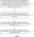
- FIG. 5 is a flowchart of a method for generating information according to an exemplary embodiment.
- the second beam signal from the second cell in the scene of high mobility may include a perpendicular beam signal perpendicular to a direction in which the UE moves, and a parallel beam signal parallel to the direction in which the UE moves.
- the second cell may be accessed according to the cell handover information as follows.
- a communication connection with a base station that manages the second cell may be established.
- the parallel beam signal may be received.
- the UE may be handed over to the second cell and receive the parallel beam signal.
- the parallel beam signal is parallel to the direction in which the UE moves. Thus, it is ensured that the UE may receive the parallel beam signal during movement, without having to switch frequently from receiving one beam signal to receiving another.
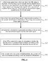
- FIG. 6 is a flowchart of a method for sending a signal according to an exemplary embodiment.
- the method for sending a signal may apply to a base station such as a 5G base station.
- the method for sending a signal may include at least one option as follows.
- UE that receives a first beam signal sent by a base station is determined.
- second identification information in a beam signal sent by a neighbor base station of the base station is received.
- the second identification information identifies at least one second beam signal sent by the neighbor base station.
- the at least one second beam signal neighbors the first beam signal.
- the second identification information is sent to the UE.
- the base station may receive second identification information that identifies at least one second beam signal (sent by a neighbor base station) that neighbors the first beam signal. For example, as shown in FIG. 2 , a first base station corresponding to a first cell 1 may transmit multiple first beam signals. For each first beam signal such as the first beam signal 11 from the first cell 1, the base station may receive identification information that identifies second beam signals 21, 22, and 23 sent by a neighbor base station of the base station.
- the base station may transmit the identification information that identifies a second beam signal to UE that receives the first beam signal, such that on one hand, the UE is allowed to determine the identification information that identifies the second beam signal to determine and receive the second beam signal without having to parse information borne on a PBCH of the second beam signal, and on the other hand, the UE may compute only the SNR of the second beam signal without having to compute the SNR of each second beam signal from the second cell. Both may reduce time consumed in a handover and speed up the handover of the UE.
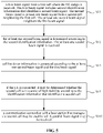
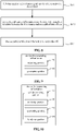
- FIG. 7 is a flowchart of a method for sending a signal according to an exemplary embodiment. As shown in FIG. 7 , the second identification information may be received as follows.
- the second beam signal may be received.
- the second beam signal may carry second identification information.
- FIG. 8 is a flowchart of a method for sending a signal according to an exemplary embodiment. As shown in FIG. 8 , the second identification information may be received as follows.
- the second identification information may be received through an interface between the base station and the neighbor base station.
- the base station may receive the second beam signal sent by the neighbor base station and acquire the second identification information in the second beam signal according to the embodiment shown in FIG. 7 .
- the second identification information may be received through an interface (such as an X2 interface) between the base station and the neighbor base station according to the embodiment shown in FIG. 8 .
- the second identification information may be received in a mode selected as needed.
- Embodiments herein further provide a device for generating information and a device for sending a signal corresponding respectively to the method for generating information and the method for sending a signal according to the previous embodiments.
- FIG. 9 is a block diagram of a device for generating information according to an exemplary embodiment.
- the device for generating information may apply to UE.
- the device for generating information may include a receiving portion and a generating portion.
- the receiving portion 91 may be adapted to: receiving a first beam signal from a first cell where the UE camps, the first beam signal including second identification information that identifies a second beam signal, the second beam signal being at least one beam signal from a second cell neighboring the first cell, the at least one second beam signal neighboring the first beam signal; determining the at least one second beam signal according to the second identification information; receiving the at least one second beam signal.
- the generating portion 92 may be adapted to generating cell handover information according to the at least one second beam signal and the first beam signal.
- the UE is in a connected state.
- the UE may be in an idle state, which is not encompassed by the claims.
- the receiving portion may be further adapted to, in response to the UE being in the idle state (which is not encompassed by the claims), while receiving the first beam signal, receiving another beam signal from the first cell that is spaced from the first beam signal by a number of beams less than a preset number.
- the generating portion may be adapted to generating the cell handover information according to the at least one second beam signal, the first beam signal, and the another beam signal.
- FIG. 10 is a block diagram of a device for generating information according to an exemplary embodiment.
- the first beam signal may further include identification information that identifies the second cell.
- the device may further include a cell determining portion and a handover portion.
- the cell determining portion 93 may be adapted to, in response to the UE being in the connected state, determining whether the second cell is in a scene of high mobility according to the identification information that identifies the second cell.
- the handover portion 94 may be adapted to, in response to the second cell being in a scene of high mobility, accessing the second cell according to the cell handover information.
- the second beam signal from the second cell in the scene of high mobility may include a perpendicular beam signal perpendicular to a direction in which the UE moves, and a parallel beam signal parallel to the direction in which the UE moves.
- the handover portion may be adapted to: establishing a communication connection with a base station that manages the second cell, and receiving the parallel beam signal.
- FIG. 11 is a block diagram of a device for sending a signal according to an exemplary embodiment.
- the device for sending a signal may apply to a base station.
- the device for sending a signal may include an equipment determining portion, an information receiving portion, and an information sending portion.
- the equipment determining portion 111 may be adapted to determining User Equipment (UE) that receives a first beam signal sent by the base station.
- UE User Equipment
- the information receiving portion 112 may be adapted to receiving second identification information in a beam signal sent by a neighbor base station of the base station.
- the second identification information may identify at least one second beam signal sent by the neighbor base station.
- the at least one second beam signal neighbors the first beam signal.
- the information sending portion 113 may be adapted to sending the second identification information to the UE.
- the information receiving portion may be adapted to receiving the second beam signal.
- the second beam signal may carry the second identification information.
- the information receiving portion may be adapted to receiving the second identification information through an interface between the base station and the neighbor base station.
- a device embodiment herein basically corresponds to a method embodiment herein, description of which may be referred to for a related part thereof.
- a device embodiment described herein is but schematic. Portions described herein as separate parts may or may not be physically separate. A part displayed as a portion may or may not be a physical portion. That is, it may be located in one place, or distributed over multiple network portions. Some or all of the portions herein may be selected as needed to achieve an effect of a solution herein. A person having ordinary skill in the art may understand and implement the above without creative effort.
- the UE includes a processor and memory.
- the memory is adapted to storing an instruction executable by the processor.
- the processor is adapted to:
- At least one embodiment herein proposes a base station.
- the base station includes a processor and memory.
- the memory is adapted to storing an instruction executable by the processor.
- the processor is adapted to:
- At least one embodiment herein proposes a computer-readable storage medium having stored thereon a computer program that, when executed by a processor, causes the processor to perform:
- At least one embodiment herein proposes a computer-readable storage medium having stored thereon a computer program that, when executed by a processor, causes the processor to perform:
- FIG. 12 is a block diagram of a device 1200 for generating information according to an exemplary embodiment.
- the device 1200 may be a mobile phone, a computer, a digital broadcast UE, a messaging device, a gaming console, a tablet, a medical device, exercise equipment, a personal digital assistant, etc.
- the device 1200 may include at least one of a processing component 1202, memory 1204, a power supply component 1206, a multimedia component 1208, an audio component 1210, an Input / Output (I / O) interface 1212, a sensor component 1214, or a communication component 1216.
- the processing component 1202 may generally control an overall operation of the device 1200, such as operations associated with display, a telephone call, data communication, a camera operation, a recording operation, etc.
- the processing component 1202 may include one or more processors 1220 to execute instructions so as to complete all or a part of an aforementioned method.
- the processing component 1202 may include one or more portions to facilitate interaction between the processing component 1202 and other components.
- the processing component 1202 may include a multimedia portion to facilitate interaction between the multimedia component 1208 and the processing component 1202.
- the memory 510 may be adapted to storing various types of data to support the operation at the device 1200. Examples of such data may include instructions of any application or method adapted to operating on the device 1200, contact data, phonebook data, messages, pictures, videos, etc.
- the memory 1204 may be realized by any type of transitory or non-transitory storage equipment or a combination thereof, such as Static Random Access Memory (SRAM), Electrically Erasable Programmable Read-Only Memory (EEPROM), Erasable Programmable Read-Only Memory (EPROM), Programmable Read-Only Memory (PROM), Read-Only Memory (ROM), magnetic memory, flash memory, a magnetic disk, a compact disk, etc.
- SRAM Static Random Access Memory
- EEPROM Electrically Erasable Programmable Read-Only Memory
- EPROM Erasable Programmable Read-Only Memory
- PROM Programmable Read-Only Memory
- ROM Read-Only Memory
- magnetic memory flash memory, a magnetic disk, a compact disk, etc.
- the power supply component 1206 may supply electric power to various components of the device 1200.
- the power supply component 1206 may include a power management system, one or more power sources, and other components related to generating, managing, and distributing electricity for the device 1200.
- the multimedia component 1208 may include a screen that provides an output interface between the device 1200 and a user.
- the screen may include a Liquid Crystal Display (LCD), a Touch Panel (TP), etc. If the screen includes a TP, the screen may be realized as a touch screen to receive a signal input by a user.
- the TP may include one or more touch sensors for sensing touch, slide, and gestures on the TP. The one or more touch sensors not only may sense the boundary of a touch or slide move, but also detect the duration and pressure related to the touch or slide move.
- the multimedia component 1208 may include at least one of a front camera or a rear camera.
- At least one of the front camera or the rear camera may receive external multimedia data.
- Each of the front camera or the rear camera may be a fixed optical lens system or may have a focal length and be capable of optical zooming.
- the audio component 1210 may be adapted to outputting and / or inputting an audio signal.
- the audio component 1210 may include a microphone (MIC).
- the MIC may be adapted to receiving an external audio signal.
- the received audio signal may be further stored in the memory 1204 or may be sent via the communication component 1216.
- the audio component 1210 may further include a loudspeaker adapted to outputting the audio signal.
- the I/O interface 1212 may provide an interface between the processing component 1202 and a peripheral interface portion.
- a peripheral interface portion may be a keypad, a click wheel, a button, etc.
- a button may include but is not limited to at least one of a homepage button, a volume button, a start button, or a lock button.
- the sensor component 1214 may include one or more sensors for assessing various states of the device 1200. For example, the sensor component 1214 may detect an on/off state of the device 1200 and relative positioning of components such as the display and the keypad of the device 1200. The sensor component 1214 may further detect a change in the position of the device 1200 or of a component of the device 1200, whether there is contact between the device 1200 and a user, the orientation or acceleration / deceleration of the device 1200, a change in the temperature of the device 1200, etc.
- the sensor component 1214 may include a proximity sensor adapted to detecting existence of a nearby object without physical contact.
- the sensor component 1214 may further include an optical sensor such as a Complementary Metal-Oxide-Semiconductor (CMOS) or a Charge-Coupled-Device (CCD) image sensor used in an imaging application.
- CMOS Complementary Metal-Oxide-Semiconductor
- CCD Charge-Coupled-Device
- the sensor component 1214 may further include an acceleration sensor, a gyroscope sensor, a magnetic sensor, a pressure sensor, a temperature sensor, etc.
- the communication component 1216 may be adapted to facilitating wired or wireless communication between the device 1200 and other equipment.
- the device 1200 may access a wireless network based on a communication standard such as Wi-Fi, 2G, 3G..., or a combination thereof.
- the communication component 1216 may broadcast related information or receive a broadcast signal from an external broadcast management system via a broadcast channel.
- the communication component 1216 may include a Near Field Communication (NFC) portion for short-range communication.
- the NFC portion may be based on technology such as Radio Frequency Identification (RFID), Infrared Data Association (IrDA), Ultra-Wideband (UWB) technology, Bluetooth (BT), etc.
- RFID Radio Frequency Identification
- IrDA Infrared Data Association
- UWB Ultra-Wideband
- Bluetooth Bluetooth
- the device 1200 may be realized by one or more electronic components such as an Application Specific Integrated Circuit (ASIC), a Digital Signal Processor (DSP), a Digital Signal Processing Device (DSPD), a Programmable Logic Device (PLD), a Field Programmable Gate Array (FPGA), a controller, a microcontroller, a microprocessor, etc., to implement any embodiment shown in FIG. 1 and FIG. 3 - FIG. 5 .
- ASIC Application Specific Integrated Circuit
- DSP Digital Signal Processor
- DSPD Digital Signal Processing Device
- PLD Programmable Logic Device
- FPGA Field Programmable Gate Array
- a non-transitory computer-readable storage medium including instructions such as memory 1204 including instructions, may be provided.
- the instructions may be executed by the processor 1220 of the device 1200 to implement an aforementioned method.
- the non-transitory computer-readable storage medium may be Read-Only Memory (ROM), Random Access Memory (RAM), Compact Disc Read-Only Memory (CD-ROM), a magnetic tape, a floppy disk, optical data storage equipment, etc.
- FIG. 13 is a block diagram of a device 1300 for sending a signal according to an exemplary embodiment.
- the device 1300 may be provided as a base station.
- the device 1300 includes a processing component 1322, a radio transmitting/receiving component 1324, an antenna component 1326, and a signal processing part dedicated to a radio interface.
- the processing component 1322 may further include one or more processors.
- a processor in the processing component 1322 may be adapted to executing any embodiment shown in FIG. 6 to FIG. 8 .
Landscapes
- Engineering & Computer Science (AREA)
- Computer Networks & Wireless Communication (AREA)
- Signal Processing (AREA)
- Mobile Radio Communication Systems (AREA)
Applications Claiming Priority (1)
| Application Number | Priority Date | Filing Date | Title |
|---|---|---|---|
| PCT/CN2017/096798 WO2019028730A1 (zh) | 2017-08-10 | 2017-08-10 | 信息生成方法及装置、信号发送方法及装置 |
Publications (3)
| Publication Number | Publication Date |
|---|---|
| EP3661252A1 EP3661252A1 (en) | 2020-06-03 |
| EP3661252A4 EP3661252A4 (en) | 2021-05-19 |
| EP3661252B1 true EP3661252B1 (en) | 2022-07-27 |
Family
ID=63095074
Family Applications (1)
| Application Number | Title | Priority Date | Filing Date |
|---|---|---|---|
| EP17920696.6A Active EP3661252B1 (en) | 2017-08-10 | 2017-08-10 | Information generating method and device, signal transmitting method and device |
Country Status (6)
| Country | Link |
|---|---|
| US (2) | US11159993B2 (zh) |
| EP (1) | EP3661252B1 (zh) |
| CN (1) | CN108401521B (zh) |
| ES (1) | ES2928216T3 (zh) |
| PL (1) | PL3661252T3 (zh) |
| WO (1) | WO2019028730A1 (zh) |
Families Citing this family (8)
| Publication number | Priority date | Publication date | Assignee | Title |
|---|---|---|---|---|
| WO2019028730A1 (zh) * | 2017-08-10 | 2019-02-14 | 北京小米移动软件有限公司 | 信息生成方法及装置、信号发送方法及装置 |
| CN110896555B (zh) * | 2018-09-13 | 2023-06-02 | 华为技术有限公司 | 一种消息处理方法和装置 |
| US10880836B2 (en) | 2019-03-28 | 2020-12-29 | At&T Intellectual Property I, L.P. | Beam provisioning for sensory data collection for 5G or other next generation networks |
| US11297554B2 (en) * | 2019-03-28 | 2022-04-05 | At&T Intellectual Property I, L.P. | Candidate beam selection and control for 5G or other next generation network |
| US11064337B2 (en) | 2019-03-28 | 2021-07-13 | At&T Intellectual Property I, L.P. | Beam as a service for 5G or other next generation network |
| US11026095B2 (en) | 2019-07-31 | 2021-06-01 | At&T Intellectual Property I, L.P. | Real-time network provisioning for distributed virtual zones of collaborative mobile devices for 5G or other next generation network |
| EP4190031A4 (en) * | 2020-07-31 | 2024-06-26 | Qualcomm Incorporated | CELL IDENTIFIER FOR PUCCH/PUSCH PATHLOSS REFERENCE OR BEAM REFERENCE SIGNAL |
| CN114710790A (zh) * | 2022-04-11 | 2022-07-05 | 新拓尼克科技(成都)有限公司 | 一种无线网络对相邻建筑的共享部署方法 |
Family Cites Families (14)
| Publication number | Priority date | Publication date | Assignee | Title |
|---|---|---|---|---|
| EP2928234B1 (en) | 2014-03-31 | 2016-05-25 | Alcatel Lucent | Methods For Operating A Mobile Station And A Base Station In A Radio Communication System, Mobile Station And Base Station Thereof |
| US9497785B2 (en) * | 2014-06-02 | 2016-11-15 | Intel Corporation | Techniques for exchanging beamforming information for a dual connection to user equipment |
| US10355761B2 (en) * | 2014-10-07 | 2019-07-16 | Mediatek Inc. | Beam administration methods for cellular/wireless networks |
| WO2016096006A1 (en) | 2014-12-18 | 2016-06-23 | Nokia Solutions And Networks Oy | Antenna beams in a wireless system |
| KR102258575B1 (ko) | 2015-03-17 | 2021-05-31 | 삼성전자 주식회사 | 전자 장치 및 이의 빔포밍을 이용한 무선 통신 방법 |
| KR20160143509A (ko) | 2015-06-04 | 2016-12-14 | 주식회사 케이티 | 빔포밍 시스템에서 이웃 셀 탐색을 위한 방법 및 장치 |
| CN106358312A (zh) * | 2015-07-17 | 2017-01-25 | 北京信威通信技术股份有限公司 | 一种多波束随机接入方法 |
| CN106374984A (zh) * | 2015-07-20 | 2017-02-01 | 中兴通讯股份有限公司 | 一种波束更新的方法和装置 |
| WO2017039505A1 (en) * | 2015-09-02 | 2017-03-09 | Telefonaktiebolaget Lm Ericsson (Publ) | Mobility procedures between beams from different radio network nodes |
| CN107027129A (zh) * | 2016-01-29 | 2017-08-08 | 中兴通讯股份有限公司 | 一种终端迁移方法、基站、终端及系统 |
| CN106686631B (zh) * | 2016-12-30 | 2020-05-19 | 宇龙计算机通信科技(深圳)有限公司 | 一种基于beam的移动性管理方法及其网元 |
| US10390296B2 (en) * | 2017-05-05 | 2019-08-20 | Htc Corporation | Device and method of handling a cell selection procedure or a cell reselection procedure |
| CN109151923B (zh) * | 2017-06-16 | 2023-12-12 | 华为技术有限公司 | 通信方法和装置 |
| WO2019028730A1 (zh) * | 2017-08-10 | 2019-02-14 | 北京小米移动软件有限公司 | 信息生成方法及装置、信号发送方法及装置 |
-
2017
- 2017-08-10 WO PCT/CN2017/096798 patent/WO2019028730A1/zh unknown
- 2017-08-10 ES ES17920696T patent/ES2928216T3/es active Active
- 2017-08-10 CN CN201780000847.1A patent/CN108401521B/zh active Active
- 2017-08-10 PL PL17920696.6T patent/PL3661252T3/pl unknown
- 2017-08-10 EP EP17920696.6A patent/EP3661252B1/en active Active
- 2017-08-10 US US16/637,741 patent/US11159993B2/en active Active
-
2021
- 2021-09-06 US US17/446,979 patent/US11653274B2/en active Active
Also Published As
| Publication number | Publication date |
|---|---|
| CN108401521A (zh) | 2018-08-14 |
| US20200213917A1 (en) | 2020-07-02 |
| CN108401521B (zh) | 2020-11-13 |
| PL3661252T3 (pl) | 2022-12-19 |
| WO2019028730A1 (zh) | 2019-02-14 |
| ES2928216T3 (es) | 2022-11-16 |
| US11159993B2 (en) | 2021-10-26 |
| EP3661252A4 (en) | 2021-05-19 |
| US20210400543A1 (en) | 2021-12-23 |
| US11653274B2 (en) | 2023-05-16 |
| EP3661252A1 (en) | 2020-06-03 |
Similar Documents
| Publication | Publication Date | Title |
|---|---|---|
| EP3661252B1 (en) | Information generating method and device, signal transmitting method and device | |
| US11452012B2 (en) | Method, apparatus for cell handover and user equipment | |
| EP3866517B1 (en) | Method and device for monitoring power-saving signal | |
| US20220086776A1 (en) | Methods and devices for configuring, sending and receiving discovery reference signal (drs) | |
| EP3771236B1 (en) | Cell access method and device | |
| US11910445B2 (en) | Random access method and device | |
| US20200045662A1 (en) | System information transmission method and device | |
| US20210250837A1 (en) | Cell reselection method and apparatus, and storage medium | |
| CN110574403B (zh) | 信息获取方法和装置、信息发送方法和装置 | |
| US20230029170A1 (en) | Method and device for obtaining information and storage medium | |
| EP3661275B1 (en) | Synchronized block receiving method and apparatus | |
| US11871430B2 (en) | Downlink control channel receiving and transmitting method and device | |
| WO2019104507A1 (zh) | 网络配置方法、网络测量方法及装置 | |
| US20240205689A1 (en) | Request sending method and device and request receiving method and device | |
| EP4325934A1 (en) | Instruction sending, information sending, and multi-card problem solving methods and devices | |
| US10492115B2 (en) | Mobility management method and apparatus | |
| US20240323790A1 (en) | Methods and apparatus for sending request and determining base station | |
| CN108713328B (zh) | 测量方法、装置、系统及存储介质 | |
| CN115699508A (zh) | 测量指示方法和装置、指示接收方法和装置 | |
| CN117561768A (zh) | 能力信息发送、能力确定方法和装置 | |
| CN115804133A (zh) | 请求发送、基站确定方法和装置 | |
| CN115707022A (zh) | 小区测量方法及装置、电子设备、存储介质 | |
| CN116614851A (zh) | 测量方法、装置、存储介质及终端 |
Legal Events
| Date | Code | Title | Description |
|---|---|---|---|
| STAA | Information on the status of an ep patent application or granted ep patent |
Free format text: STATUS: THE INTERNATIONAL PUBLICATION HAS BEEN MADE |
|
| PUAI | Public reference made under article 153(3) epc to a published international application that has entered the european phase |
Free format text: ORIGINAL CODE: 0009012 |
|
| STAA | Information on the status of an ep patent application or granted ep patent |
Free format text: STATUS: REQUEST FOR EXAMINATION WAS MADE |
|
| 17P | Request for examination filed |
Effective date: 20200228 |
|
| AK | Designated contracting states |
Kind code of ref document: A1 Designated state(s): AL AT BE BG CH CY CZ DE DK EE ES FI FR GB GR HR HU IE IS IT LI LT LU LV MC MK MT NL NO PL PT RO RS SE SI SK SM TR |
|
| AX | Request for extension of the european patent |
Extension state: BA ME |
|
| RAP1 | Party data changed (applicant data changed or rights of an application transferred) |
Owner name: BEIJING XIAOMI MOBILE SOFTWARE CO., LTD. |
|
| RIN1 | Information on inventor provided before grant (corrected) |
Inventor name: LIU, YANG |
|
| DAV | Request for validation of the european patent (deleted) | ||
| DAX | Request for extension of the european patent (deleted) | ||
| A4 | Supplementary search report drawn up and despatched |
Effective date: 20210420 |
|
| RIC1 | Information provided on ipc code assigned before grant |
Ipc: H04W 36/08 20090101AFI20210414BHEP Ipc: H04W 36/00 20090101ALN20210414BHEP Ipc: H04W 48/12 20090101ALN20210414BHEP Ipc: H04W 48/16 20090101ALN20210414BHEP Ipc: H04W 48/20 20090101ALN20210414BHEP |
|
| REG | Reference to a national code |
Ref country code: DE Ref legal event code: R079 Ref document number: 602017060055 Country of ref document: DE Free format text: PREVIOUS MAIN CLASS: H04W0024020000 Ipc: H04W0036080000 |
|
| GRAP | Despatch of communication of intention to grant a patent |
Free format text: ORIGINAL CODE: EPIDOSNIGR1 |
|
| STAA | Information on the status of an ep patent application or granted ep patent |
Free format text: STATUS: GRANT OF PATENT IS INTENDED |
|
| RIC1 | Information provided on ipc code assigned before grant |
Ipc: H04W 48/20 20090101ALN20220325BHEP Ipc: H04W 48/16 20090101ALN20220325BHEP Ipc: H04W 48/12 20090101ALN20220325BHEP Ipc: H04W 36/00 20090101ALN20220325BHEP Ipc: H04W 36/08 20090101AFI20220325BHEP |
|
| INTG | Intention to grant announced |
Effective date: 20220419 |
|
| GRAS | Grant fee paid |
Free format text: ORIGINAL CODE: EPIDOSNIGR3 |
|
| GRAA | (expected) grant |
Free format text: ORIGINAL CODE: 0009210 |
|
| STAA | Information on the status of an ep patent application or granted ep patent |
Free format text: STATUS: THE PATENT HAS BEEN GRANTED |
|
| AK | Designated contracting states |
Kind code of ref document: B1 Designated state(s): AL AT BE BG CH CY CZ DE DK EE ES FI FR GB GR HR HU IE IS IT LI LT LU LV MC MK MT NL NO PL PT RO RS SE SI SK SM TR |
|
| REG | Reference to a national code |
Ref country code: CH Ref legal event code: EP |
|
| REG | Reference to a national code |
Ref country code: AT Ref legal event code: REF Ref document number: 1507936 Country of ref document: AT Kind code of ref document: T Effective date: 20220815 |
|
| REG | Reference to a national code |
Ref country code: DE Ref legal event code: R096 Ref document number: 602017060055 Country of ref document: DE |
|
| REG | Reference to a national code |
Ref country code: IE Ref legal event code: FG4D |
|
| REG | Reference to a national code |
Ref country code: NL Ref legal event code: FP |
|
| REG | Reference to a national code |
Ref country code: RO Ref legal event code: EPE |
|
| REG | Reference to a national code |
Ref country code: LT Ref legal event code: MG9D |
|
| REG | Reference to a national code |
Ref country code: ES Ref legal event code: FG2A Ref document number: 2928216 Country of ref document: ES Kind code of ref document: T3 Effective date: 20221116 |
|
| PG25 | Lapsed in a contracting state [announced via postgrant information from national office to epo] |
Ref country code: SE Free format text: LAPSE BECAUSE OF FAILURE TO SUBMIT A TRANSLATION OF THE DESCRIPTION OR TO PAY THE FEE WITHIN THE PRESCRIBED TIME-LIMIT Effective date: 20220727 Ref country code: RS Free format text: LAPSE BECAUSE OF FAILURE TO SUBMIT A TRANSLATION OF THE DESCRIPTION OR TO PAY THE FEE WITHIN THE PRESCRIBED TIME-LIMIT Effective date: 20220727 Ref country code: PT Free format text: LAPSE BECAUSE OF FAILURE TO SUBMIT A TRANSLATION OF THE DESCRIPTION OR TO PAY THE FEE WITHIN THE PRESCRIBED TIME-LIMIT Effective date: 20221128 Ref country code: NO Free format text: LAPSE BECAUSE OF FAILURE TO SUBMIT A TRANSLATION OF THE DESCRIPTION OR TO PAY THE FEE WITHIN THE PRESCRIBED TIME-LIMIT Effective date: 20221027 Ref country code: LV Free format text: LAPSE BECAUSE OF FAILURE TO SUBMIT A TRANSLATION OF THE DESCRIPTION OR TO PAY THE FEE WITHIN THE PRESCRIBED TIME-LIMIT Effective date: 20220727 Ref country code: LT Free format text: LAPSE BECAUSE OF FAILURE TO SUBMIT A TRANSLATION OF THE DESCRIPTION OR TO PAY THE FEE WITHIN THE PRESCRIBED TIME-LIMIT Effective date: 20220727 Ref country code: FI Free format text: LAPSE BECAUSE OF FAILURE TO SUBMIT A TRANSLATION OF THE DESCRIPTION OR TO PAY THE FEE WITHIN THE PRESCRIBED TIME-LIMIT Effective date: 20220727 |
|
| REG | Reference to a national code |
Ref country code: AT Ref legal event code: MK05 Ref document number: 1507936 Country of ref document: AT Kind code of ref document: T Effective date: 20220727 |
|
| PG25 | Lapsed in a contracting state [announced via postgrant information from national office to epo] |
Ref country code: IS Free format text: LAPSE BECAUSE OF FAILURE TO SUBMIT A TRANSLATION OF THE DESCRIPTION OR TO PAY THE FEE WITHIN THE PRESCRIBED TIME-LIMIT Effective date: 20221127 Ref country code: HR Free format text: LAPSE BECAUSE OF FAILURE TO SUBMIT A TRANSLATION OF THE DESCRIPTION OR TO PAY THE FEE WITHIN THE PRESCRIBED TIME-LIMIT Effective date: 20220727 Ref country code: GR Free format text: LAPSE BECAUSE OF FAILURE TO SUBMIT A TRANSLATION OF THE DESCRIPTION OR TO PAY THE FEE WITHIN THE PRESCRIBED TIME-LIMIT Effective date: 20221028 |
|
| REG | Reference to a national code |
Ref country code: CH Ref legal event code: PL |
|
| PG25 | Lapsed in a contracting state [announced via postgrant information from national office to epo] |
Ref country code: SM Free format text: LAPSE BECAUSE OF FAILURE TO SUBMIT A TRANSLATION OF THE DESCRIPTION OR TO PAY THE FEE WITHIN THE PRESCRIBED TIME-LIMIT Effective date: 20220727 Ref country code: MC Free format text: LAPSE BECAUSE OF FAILURE TO SUBMIT A TRANSLATION OF THE DESCRIPTION OR TO PAY THE FEE WITHIN THE PRESCRIBED TIME-LIMIT Effective date: 20220727 Ref country code: LU Free format text: LAPSE BECAUSE OF NON-PAYMENT OF DUE FEES Effective date: 20220810 Ref country code: LI Free format text: LAPSE BECAUSE OF NON-PAYMENT OF DUE FEES Effective date: 20220831 Ref country code: DK Free format text: LAPSE BECAUSE OF FAILURE TO SUBMIT A TRANSLATION OF THE DESCRIPTION OR TO PAY THE FEE WITHIN THE PRESCRIBED TIME-LIMIT Effective date: 20220727 Ref country code: CZ Free format text: LAPSE BECAUSE OF FAILURE TO SUBMIT A TRANSLATION OF THE DESCRIPTION OR TO PAY THE FEE WITHIN THE PRESCRIBED TIME-LIMIT Effective date: 20220727 Ref country code: CH Free format text: LAPSE BECAUSE OF NON-PAYMENT OF DUE FEES Effective date: 20220831 Ref country code: AT Free format text: LAPSE BECAUSE OF FAILURE TO SUBMIT A TRANSLATION OF THE DESCRIPTION OR TO PAY THE FEE WITHIN THE PRESCRIBED TIME-LIMIT Effective date: 20220727 |
|
| REG | Reference to a national code |
Ref country code: DE Ref legal event code: R097 Ref document number: 602017060055 Country of ref document: DE Ref country code: BE Ref legal event code: MM Effective date: 20220831 |
|
| PG25 | Lapsed in a contracting state [announced via postgrant information from national office to epo] |
Ref country code: SK Free format text: LAPSE BECAUSE OF FAILURE TO SUBMIT A TRANSLATION OF THE DESCRIPTION OR TO PAY THE FEE WITHIN THE PRESCRIBED TIME-LIMIT Effective date: 20220727 Ref country code: EE Free format text: LAPSE BECAUSE OF FAILURE TO SUBMIT A TRANSLATION OF THE DESCRIPTION OR TO PAY THE FEE WITHIN THE PRESCRIBED TIME-LIMIT Effective date: 20220727 |
|
| PLBE | No opposition filed within time limit |
Free format text: ORIGINAL CODE: 0009261 |
|
| STAA | Information on the status of an ep patent application or granted ep patent |
Free format text: STATUS: NO OPPOSITION FILED WITHIN TIME LIMIT |
|
| P01 | Opt-out of the competence of the unified patent court (upc) registered |
Effective date: 20230523 |
|
| PG25 | Lapsed in a contracting state [announced via postgrant information from national office to epo] |
Ref country code: AL Free format text: LAPSE BECAUSE OF FAILURE TO SUBMIT A TRANSLATION OF THE DESCRIPTION OR TO PAY THE FEE WITHIN THE PRESCRIBED TIME-LIMIT Effective date: 20220727 |
|
| 26N | No opposition filed |
Effective date: 20230502 |
|
| PG25 | Lapsed in a contracting state [announced via postgrant information from national office to epo] |
Ref country code: IE Free format text: LAPSE BECAUSE OF NON-PAYMENT OF DUE FEES Effective date: 20220810 |
|
| PG25 | Lapsed in a contracting state [announced via postgrant information from national office to epo] |
Ref country code: SI Free format text: LAPSE BECAUSE OF FAILURE TO SUBMIT A TRANSLATION OF THE DESCRIPTION OR TO PAY THE FEE WITHIN THE PRESCRIBED TIME-LIMIT Effective date: 20220727 |
|
| PG25 | Lapsed in a contracting state [announced via postgrant information from national office to epo] |
Ref country code: BE Free format text: LAPSE BECAUSE OF NON-PAYMENT OF DUE FEES Effective date: 20220831 |
|
| PGFP | Annual fee paid to national office [announced via postgrant information from national office to epo] |
Ref country code: NL Payment date: 20230821 Year of fee payment: 7 |
|
| PGFP | Annual fee paid to national office [announced via postgrant information from national office to epo] |
Ref country code: RO Payment date: 20230727 Year of fee payment: 7 Ref country code: IT Payment date: 20230825 Year of fee payment: 7 Ref country code: GB Payment date: 20230822 Year of fee payment: 7 |
|
| PGFP | Annual fee paid to national office [announced via postgrant information from national office to epo] |
Ref country code: PL Payment date: 20230727 Year of fee payment: 7 Ref country code: FR Payment date: 20230828 Year of fee payment: 7 Ref country code: DE Payment date: 20230821 Year of fee payment: 7 |
|
| PGFP | Annual fee paid to national office [announced via postgrant information from national office to epo] |
Ref country code: ES Payment date: 20231027 Year of fee payment: 7 |
|
| PG25 | Lapsed in a contracting state [announced via postgrant information from national office to epo] |
Ref country code: CY Free format text: LAPSE BECAUSE OF FAILURE TO SUBMIT A TRANSLATION OF THE DESCRIPTION OR TO PAY THE FEE WITHIN THE PRESCRIBED TIME-LIMIT Effective date: 20220727 |
|
| PG25 | Lapsed in a contracting state [announced via postgrant information from national office to epo] |
Ref country code: MK Free format text: LAPSE BECAUSE OF FAILURE TO SUBMIT A TRANSLATION OF THE DESCRIPTION OR TO PAY THE FEE WITHIN THE PRESCRIBED TIME-LIMIT Effective date: 20220727 Ref country code: HU Free format text: LAPSE BECAUSE OF FAILURE TO SUBMIT A TRANSLATION OF THE DESCRIPTION OR TO PAY THE FEE WITHIN THE PRESCRIBED TIME-LIMIT; INVALID AB INITIO Effective date: 20170810 |
|
| PG25 | Lapsed in a contracting state [announced via postgrant information from national office to epo] |
Ref country code: BG Free format text: LAPSE BECAUSE OF FAILURE TO SUBMIT A TRANSLATION OF THE DESCRIPTION OR TO PAY THE FEE WITHIN THE PRESCRIBED TIME-LIMIT Effective date: 20220727 |