EP3661186A1 - Control apparatus, imaging apparatus, and program - Google Patents
Control apparatus, imaging apparatus, and program Download PDFInfo
- Publication number
- EP3661186A1 EP3661186A1 EP19212036.8A EP19212036A EP3661186A1 EP 3661186 A1 EP3661186 A1 EP 3661186A1 EP 19212036 A EP19212036 A EP 19212036A EP 3661186 A1 EP3661186 A1 EP 3661186A1
- Authority
- EP
- European Patent Office
- Prior art keywords
- image
- image sensor
- coordinate
- imaging
- angle
- Prior art date
- Legal status (The legal status is an assumption and is not a legal conclusion. Google has not performed a legal analysis and makes no representation as to the accuracy of the status listed.)
- Granted
Links
Images



Classifications
-
- H—ELECTRICITY
- H04—ELECTRIC COMMUNICATION TECHNIQUE
- H04N—PICTORIAL COMMUNICATION, e.g. TELEVISION
- H04N23/00—Cameras or camera modules comprising electronic image sensors; Control thereof
- H04N23/60—Control of cameras or camera modules
-
- G—PHYSICS
- G08—SIGNALLING
- G08B—SIGNALLING SYSTEMS, e.g. PERSONAL CALLING SYSTEMS; ORDER TELEGRAPHS; ALARM SYSTEMS
- G08B13/00—Burglar, theft or intruder alarms
- G08B13/18—Actuation by interference with heat, light, or radiation of shorter wavelength; Actuation by intruding sources of heat, light, or radiation of shorter wavelength
- G08B13/189—Actuation by interference with heat, light, or radiation of shorter wavelength; Actuation by intruding sources of heat, light, or radiation of shorter wavelength using passive radiation detection systems
- G08B13/194—Actuation by interference with heat, light, or radiation of shorter wavelength; Actuation by intruding sources of heat, light, or radiation of shorter wavelength using passive radiation detection systems using image scanning and comparing systems
- G08B13/196—Actuation by interference with heat, light, or radiation of shorter wavelength; Actuation by intruding sources of heat, light, or radiation of shorter wavelength using passive radiation detection systems using image scanning and comparing systems using television cameras
- G08B13/19678—User interface
- G08B13/19686—Interfaces masking personal details for privacy, e.g. blurring faces, vehicle license plates
-
- H—ELECTRICITY
- H04—ELECTRIC COMMUNICATION TECHNIQUE
- H04N—PICTORIAL COMMUNICATION, e.g. TELEVISION
- H04N23/00—Cameras or camera modules comprising electronic image sensors; Control thereof
- H04N23/60—Control of cameras or camera modules
- H04N23/695—Control of camera direction for changing a field of view, e.g. pan, tilt or based on tracking of objects
-
- G—PHYSICS
- G08—SIGNALLING
- G08B—SIGNALLING SYSTEMS, e.g. PERSONAL CALLING SYSTEMS; ORDER TELEGRAPHS; ALARM SYSTEMS
- G08B13/00—Burglar, theft or intruder alarms
- G08B13/18—Actuation by interference with heat, light, or radiation of shorter wavelength; Actuation by intruding sources of heat, light, or radiation of shorter wavelength
- G08B13/189—Actuation by interference with heat, light, or radiation of shorter wavelength; Actuation by intruding sources of heat, light, or radiation of shorter wavelength using passive radiation detection systems
- G08B13/194—Actuation by interference with heat, light, or radiation of shorter wavelength; Actuation by intruding sources of heat, light, or radiation of shorter wavelength using passive radiation detection systems using image scanning and comparing systems
- G08B13/196—Actuation by interference with heat, light, or radiation of shorter wavelength; Actuation by intruding sources of heat, light, or radiation of shorter wavelength using passive radiation detection systems using image scanning and comparing systems using television cameras
- G08B13/19678—User interface
- G08B13/19689—Remote control of cameras, e.g. remote orientation or image zooming control for a PTZ camera
-
- G—PHYSICS
- G08—SIGNALLING
- G08B—SIGNALLING SYSTEMS, e.g. PERSONAL CALLING SYSTEMS; ORDER TELEGRAPHS; ALARM SYSTEMS
- G08B25/00—Alarm systems in which the location of the alarm condition is signalled to a central station, e.g. fire or police telegraphic systems
- G08B25/01—Alarm systems in which the location of the alarm condition is signalled to a central station, e.g. fire or police telegraphic systems characterised by the transmission medium
- G08B25/08—Alarm systems in which the location of the alarm condition is signalled to a central station, e.g. fire or police telegraphic systems characterised by the transmission medium using communication transmission lines
-
- H—ELECTRICITY
- H04—ELECTRIC COMMUNICATION TECHNIQUE
- H04N—PICTORIAL COMMUNICATION, e.g. TELEVISION
- H04N23/00—Cameras or camera modules comprising electronic image sensors; Control thereof
- H04N23/50—Constructional details
- H04N23/54—Mounting of pick-up tubes, electronic image sensors, deviation or focusing coils
-
- H—ELECTRICITY
- H04—ELECTRIC COMMUNICATION TECHNIQUE
- H04N—PICTORIAL COMMUNICATION, e.g. TELEVISION
- H04N23/00—Cameras or camera modules comprising electronic image sensors; Control thereof
- H04N23/50—Constructional details
- H04N23/55—Optical parts specially adapted for electronic image sensors; Mounting thereof
-
- H—ELECTRICITY
- H04—ELECTRIC COMMUNICATION TECHNIQUE
- H04N—PICTORIAL COMMUNICATION, e.g. TELEVISION
- H04N23/00—Cameras or camera modules comprising electronic image sensors; Control thereof
- H04N23/58—Means for changing the camera field of view without moving the camera body, e.g. nutating or panning of optics or image sensors
-
- H—ELECTRICITY
- H04—ELECTRIC COMMUNICATION TECHNIQUE
- H04N—PICTORIAL COMMUNICATION, e.g. TELEVISION
- H04N23/00—Cameras or camera modules comprising electronic image sensors; Control thereof
- H04N23/60—Control of cameras or camera modules
- H04N23/63—Control of cameras or camera modules by using electronic viewfinders
- H04N23/633—Control of cameras or camera modules by using electronic viewfinders for displaying additional information relating to control or operation of the camera
- H04N23/635—Region indicators; Field of view indicators
-
- H—ELECTRICITY
- H04—ELECTRIC COMMUNICATION TECHNIQUE
- H04N—PICTORIAL COMMUNICATION, e.g. TELEVISION
- H04N23/00—Cameras or camera modules comprising electronic image sensors; Control thereof
- H04N23/60—Control of cameras or camera modules
- H04N23/67—Focus control based on electronic image sensor signals
-
- H—ELECTRICITY
- H04—ELECTRIC COMMUNICATION TECHNIQUE
- H04N—PICTORIAL COMMUNICATION, e.g. TELEVISION
- H04N23/00—Cameras or camera modules comprising electronic image sensors; Control thereof
- H04N23/60—Control of cameras or camera modules
- H04N23/69—Control of means for changing angle of the field of view, e.g. optical zoom objectives or electronic zooming
-
- H—ELECTRICITY
- H04—ELECTRIC COMMUNICATION TECHNIQUE
- H04N—PICTORIAL COMMUNICATION, e.g. TELEVISION
- H04N23/00—Cameras or camera modules comprising electronic image sensors; Control thereof
- H04N23/80—Camera processing pipelines; Components thereof
-
- H—ELECTRICITY
- H04—ELECTRIC COMMUNICATION TECHNIQUE
- H04N—PICTORIAL COMMUNICATION, e.g. TELEVISION
- H04N5/00—Details of television systems
- H04N5/222—Studio circuitry; Studio devices; Studio equipment
- H04N5/262—Studio circuits, e.g. for mixing, switching-over, change of character of image, other special effects ; Cameras specially adapted for the electronic generation of special effects
- H04N5/2621—Cameras specially adapted for the electronic generation of special effects during image pickup, e.g. digital cameras, camcorders, video cameras having integrated special effects capability
-
- H—ELECTRICITY
- H04—ELECTRIC COMMUNICATION TECHNIQUE
- H04N—PICTORIAL COMMUNICATION, e.g. TELEVISION
- H04N7/00—Television systems
- H04N7/18—Closed-circuit television [CCTV] systems, i.e. systems in which the video signal is not broadcast
- H04N7/183—Closed-circuit television [CCTV] systems, i.e. systems in which the video signal is not broadcast for receiving images from a single remote source
Definitions
- the present invention relates to a control apparatus that can adjust a focal plane, an imaging apparatus having the same, and a program (or storage medium).
- a network camera may not be able to obtain a deep depth of field in a scene such as a long house, corridor, and parking lot depending on lens performance, and imaging condition such as an angle of view and an F-number.
- imaging condition such as an angle of view and an F-number.
- JP Japanese Patent Application Laid-Open No.
- JP 5-53166 discloses a camera in which an image sensor inclines to an imaging optical axis plane orthogonal to the optical axis.
- Some network cameras have a privacy mask function that hides a specified area from the viewpoint of privacy protection, a detection function that detects a moving object and taking away by analyzing the image, or an area data reduction function that makes different a compression ratio for each image area.
- a privacy mask function that hides a specified area from the viewpoint of privacy protection
- a detection function that detects a moving object and taking away by analyzing the image
- an area data reduction function that makes different a compression ratio for each image area.
- the present invention provides a control apparatus, an imaging apparatus, a storage medium (program), each of which can effectively use a privacy mask function, a detection function, or an area data reduction function without requiring resetting of a target position by a user even if an angle of an imaging plane is changed.
- the present invention in its first aspect provides a control apparatus as claimed in claims 1 to 3.
- the present invention in its second aspect provides an imaging apparatus as claimed in claim 4.
- the present invention in its second aspect provides a program as claimed in claim 5.
- the present invention is applicable to an apparatus and means for controlling a device having a function of capturing a motion image.
- the device having a function of capturing the motion image includes, for example, an imaging apparatus, such as a network camera, a video camera, and a still camera, a mobile phone having an imaging function, and a portable information terminal.
- an imaging apparatus such as a network camera, a video camera, and a still camera
- a mobile phone having an imaging function such as a portable information terminal.
- This embodiment will discuss the imaging apparatus, such as the network camera, to which the present invention is applied.
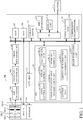
- FIG. 1 illustrates a configuration of an imaging apparatus 100 according to one embodiment of the present invention.
- a CPU 101 includes a zoom control unit 101-1, a focus control unit 101-2, a tilt control unit 101-3, an image evaluation area determination unit 101-4, a pan head control unit 101-5, a control unit 101-6, and a coordinate information management unit 101-7, and governs an overall control of the imaging apparatus 100.
- the imaging apparatus 100 is controlled by the CPU 101 provided therein, but the present invention is not limited to this embodiment.
- the imaging apparatus 100 may be controlled from the outside by a control apparatus having a function of the CPU 101, which is separate from the imaging apparatus 100.
- An imaging unit 102 includes an imaging optical system and an image sensor 102-4.
- the imaging optical system includes a zoom lens 102-1, a focus lens 102-2, and a diaphragm (aperture stop) 102-3.
- the image sensor 102-4 includes an image sensor or the like, and generates an image by photoelectrically converting an optical image formed via the imaging optical system.
- the zoom control unit 101-1 moves the zoom lens 102-1 along the optical axis via a driver 108.
- the focus control unit 101-2 moves the focus lens 102-2 along the optical axis via the driver 108.
- the control unit 101-6 operates the diaphragm 102-3 via the driver 108.
- the tilt control unit (angle control unit) 101-3 controls a tilt angle of the image sensor 102-4 via the driver 108 so as to tilt the imaging plane relative to the imaging optical axis plane orthogonal to the optical axis.
- the pan head control unit 101-5 controls a movement of a pan head 110 via the actuator 111, and rotates the imaging unit 102 in the horizontal direction and the vertical direction. Thereby, an image can be captured while the imaging direction is changed.
- the pan head 110 includes a pan driver and a tilt driver.
- the pan driver can rotate in the lateral direction from -175° to +175°, and rotates the imaging unit 102 in the horizontal direction.
- the tilt driver can rotate from 0° or the horizontal direction to 90° or the upright direction, and rotates the imaging unit 102 in the vertical direction.
- the image sensor 102-4 photoelectrically converts light that has passed the imaging optical system and generates an analog image signal.
- the generated analog image signal undergoes amplification processing by sampling processing, such as correlated double sampling, and then input into an A/D converter 103.
- An parameter used for the amplification processing is controlled by the CPU 101.
- the A/D converter 103 converts the amplified analog image signal into a digital image signal, and outputs the digital image signal to an image input controller 104.
- the image input controller 104 receives the digital image signal and outputs it to an image processing unit 105.
- the image processing unit 105 performs various digital image processing for the digital image signal based on sensitivity information during imaging output from the image sensor 102-4, such as an AGC gain and an ISO speed, and then passes through a bus 106, and stored in a RAM 107.
- Various digital image processing includes, for example, offset processing, gamma correction processing, gain processing, RGB interpolation processing, noise reduction processing, contour correction processing, color tone correction processing, and light source type determination processing.
- the image processing unit 105 performs OSD processing for superimposing character information on an image, and masking processing for concealing a masking area (private mask area) through a mask image superimposition and mosaic/blur processing.
- the coordinate information (positional information) of the masking area is set by the user operation from an input unit 114 or a network 116 and stored in the coordinate information management unit (or acquisition unit) 101-7.
- the coordinate information management unit 101-7 updates the coordinate information of the masking area based on the stored coordinate information and the tilt angle of the image sensor 102-4 acquired from the tilt control unit 101-3, and notifies the image processing unit 105 of it.
- the RAM 107 includes a volatile memory such as an SRAM and a DRAM.
- the ROM 109 includes a nonvolatile memory such as an EEPROM and a flash memory.
- a storage device 112 includes a storage device such as an HDD, SSD, or eMMC.
- a program for realizing the function according to this embodiment and data used when the program is executed are stored in the ROM 109 or the storage device 112. The program and data are properly installed in the RAM 107 via the bus 106 under control of the CPU 101 and used by the CPU 101.
- An I/F 113 includes a variety of I/Fs relating to an input and an output.
- the I/F 113 is connected to the input unit 114 such as an operation key including a release switch and a power switch, a cross key, a joystick, a touch panel, a keyboard, and a pointing device (such as a mouse), and notifies the CPU 101 of instruction information.
- the I/F 113 is connected to a display unit 115 such as an LCD display, and displays an image and operation menu information temporarily recorded in the RAM 107.
- the I/F 113 is connected to the network 116 via a LAN.
- An image evaluation unit 117 calculates an evaluation value of a designated area of the image in accordance with the control instruction from the image evaluation area determination unit 101-4. More specifically, the image evaluation unit 117 acquires an image from the RAM 107, and calculates an evaluation value relating to the contrast of the specific frequency based on the luminance value of the designated area.
- An image analysis unit 118 performs an image analysis such as a face detection, a person detection, a moving object detection, a passage detection, a congestion detection, a trajectory detection, and a leaving/taking away detection.
- the image analysis result is notified to the CPU 101.
- the coordinate information (positional information) of an image analysis area that is a target of the image analysis is set by the user operation through the input unit 114 or the network 116 and stored in the coordinate information management unit 101-7.
- the coordinate information management unit 101-7 updates the coordinate information of the image analysis area based on the stored coordinate information and the tilt angle of the image sensor 102-4 acquired from the tilt control unit 101-3, and notifies the image analysis unit 118 of it.
- the image analysis area includes not only an area having a predetermined area but also an image analysis line composed of one or more lines.
- the compression/decompression unit (CODEC) 119 performs compression processing for an image according to a control instruction from the CPU 101 and generates compressed data.
- the compressed data is output to the display unit 115 and the network 116 via the I/F 113.
- the CODEC 119 performs decompression processing of a predetermined format for the compressed data stored in the storage device 112 and generates decompressed data. More specifically, the compression processing conforming to the JPEG standard is performed for a still image, and the compression/decompression processing conforming to a standard such as MOTION-JPEG, MPEG2, AVC/H. 264 and AVC/H. 265 is performed for a motion image.
- the CODEC 119 can designate the compression rate of the designated area (compression rate designated area).
- the coordinate information (positional information) and the compression rate of the compression rate designated area set by the user operation from the input unit 114 or the network 116 are held in the coordinate information management unit 101-7.
- the coordinate information management unit 101-7 updates the coordinate information of the compression rate designated area based on the held coordinate and the tilt angle of the image sensor 102-4 acquired from the tilt control unit 101-3, and together with the compression rate, and notifies the CODEC 119 of the coordinate information and the compression rate.
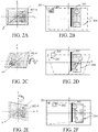
- FIGs. 2A to 2F schematically show the tilt and focal plane of the image sensor.
- FIGs. 2A, 2C, and 2E show states of the image sensor 102-4.
- FIG. 2B shows an image captured without tilting the image sensor 102-4 as illustrated in FIG. 2A.
- FIG. 2D shows an image captured by tilting the image sensor 102-4 in the tilt direction, as illustrated in FIG. 2C.
- FIG. 2F shows an image captured by tilting the image sensor 102-4 in the pan direction, as illustrated in FIG. 2E .
- a masking area 202 is set by the image processing unit 105 so as to conceal an object 201.
- An image analysis line 203 and a compression rate designated area 204 are set.
- the image analysis line 203 is set as the target of the image analysis, but the image analysis area may be set by a plurality of vertices.
- the position of the object 201 in the image changes from the position before the image sensor 102-4 is tilted, as illustrated in FIGs. 2D and 2F .
- the position of the masking area 202 is maintained, the object 201 is not concealed.
- the positional relationship between the image analysis line 203 and the compression rate designated area 204 relative to the image also changes from the positional relationship before the image sensor 102-4 is tilted.
- FIGs. 3A to 3C schematically illustrate a trapezoidal distortion caused by the tilt of the image sensor 102-4.
- FIG.3A shows the imaging plane tilted by an angle ⁇ .
- FIGs. 3B and 3C show imaging planes on the yz plane and the xz plane, respectively.
- An arbitrary position P on the imaging plane before the image sensor 102-4 is tilted is projected onto a projection position P' on the imaging plane after the image sensor 102-4 is tilted by the angle ⁇ .
- an x coordinate x' and a y coordinate y' of the projection position P' can be expressed by using an x coordinate x and a y coordinate y of the position P, the projection transformation, and the following expressions (1) and (2).
- x ⁇ x L + y ⁇ sin ⁇
- L y ⁇ Ly Lcos ⁇ ⁇ ysin ⁇
- tilting the image sensor 102-4 causes a trapezoidal distortion in the image.
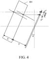
- FIG. 4 schematically illustrates an image movement caused by the tilt of the image sensor 102-4.
- An optical filter 401 is attached to the image sensor 102-4 in order to reduce the image degradation and moire due to the infrared ray.
- the projection position P' of the arbitrary position P on the imaging plane before the image sensor 102-4 is tilted changes to a projection position P" due to the refraction influence of the optical filter 401.
- d is a thickness of the optical filter 401
- n is a refractive index
- g is a (minimum) distance between the image sensor 102-4 and the optical filter 401
- y ⁇ shift gtan ⁇ + d sin ⁇ n ⁇ sin 2 ⁇
- This embodiment controls the focal plane by tilting the image sensor 102-4, but the present invention is not limited to this embodiment.
- the focal plane may be controlled by tilting an unillustrated tilt lens provided in the imaging optical system via the driver 108 and the tilt control unit 101-3.
- FIG. 5 a description will be given of coordinate correction processing according to this example executed for a specific area in an image (at least one of the masking area, the image analysis area, and the compression rate designated area) when the image sensor 102-4 is tilted in the tilt direction.
- the coordinate correction processing is part of processing in the program stored in the ROM 109.
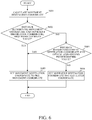
- FIG. 5 is a flowchart showing the coordinate correction processing of this example.
- the coordinate correction processing according to this example is developed in the RAM 107 during the operation of the imaging apparatus 100, and executed by the CPU 101 at the timing at which the image sensor 102-4 captures an image, or the timing at which the tilt control unit 101-3 controls the tilt of the image sensor 102-4.
- the CPU 101 acquires the tilt angle of the image sensor 102-4 from the tilt control unit 101-3.
- the CPU 101 determines whether or not the tilt angle of the image sensor 102-4 has changed. More specifically, the CPU 101 determines whether the tilt angle of the image sensor 102-4 acquired in the last coordinate correction processing recorded in the RAM 107 is different from the tilt angle of the image sensor 102-4 acquired in the step S501. If the tilt angle of the image sensor 102-4 has changed, the flow proceeds to the step S503. If the tilt angle of the image sensor 102-4 has not changed, the coordinate correction processing ends.
- the coordinate information management unit 101-7 performs coordinate recalculation processing for all the specific areas held.
- the specific area includes an image analysis line.
- FIG. 6 is a flowchart showing the coordinate recalculation processing according to this example.
- the coordinate information management unit 101-7 calculates a coordinate of a movement destination ("destination coordinate" hereinafter) for each vertex constituting all specific areas that are stored.
- the coordinate information management unit 101-7 calculates the destination coordinate based on the refraction influence of the optical filter 401.
- This example calculates the destination coordinate based on the refraction influence of the optical filter 401, but the present invention is not limited to this example.
- the destination coordinate may be calculated based on another factor that affects the optical spatial axis, such as a trapezoidal distortion due to the angle between the imaging plane and the optical axis, the image distortion due to the lens aberration, or the orientation of the pan head 110.
- the coordinate information management unit 101-7 determines whether the distance between the pre-movement coordinate (x, y) and the destination coordinate (x", y") is equal to or less than a first predetermined value.
- the first predetermined value is determined as the maximum size that does not affect each function based on the pixel size of the input/output image in the image processing unit 105, the pixel size of the analysis image in the image analysis unit 118, or the compression block size in the CODEC 119.
- the first predetermined value can also be set from the input unit 114 or the network 116 through the I/F 113.
- the flow proceeds to the step S605, and if it is greater than the first predetermined value, the flow proceeds to the step S603.
- the calculated distance is equal to the first predetermined value, which step to proceed to may be arbitrarily set.
- the coordinate information management unit 101-7 determines whether the distance from the destination coordinate (x", y") to the optical axis is equal to or less than a second predetermined value.
- the second predetermined value is determined as the maximum size that does not affect each function based on the tilt angle of the image sensor 102-4, the pixel size of the input/output image in the image processing unit 105, the pixel size of the analysis image in the image analysis unit 118, or the compression block size in the CODEC 119.
- the second predetermined value can also be set from the input unit 114 or the network 116 through the I/F 113.
- the flow proceeds to the step S605, and when it is greater than the second predetermined value, the flow proceeds to the step S604.
- the calculated distance is equal to the second predetermined value, which step to proceed to can be arbitrarily set.
- the coordinate information management unit 101-7 sets the destination coordinate to the result calculated in the step S602 or the destination coordinate (x", y").
- the coordinate information management unit 101-7 sets the destination coordinate to the pre-movement coordinate (x, y).
- the coordinate recalculation processing is executed for the vertices constituting all the specific areas stored by the coordinate information management unit 101-7. After the processing is performed for all the vertices (after the coordinate recalculation processing ends), the flow proceeds to the step S504.
- the coordinate information management unit 101-7 determines whether a change in position, size, or shape of all stored masking areas is equal to or greater than a first threshold value.
- the first threshold value can be determined as the maximum size with which the tilt angle of the image sensor 102-4 does not affect the masking area, based on the pixel size of the input/output image in the image processing unit 105.
- the first threshold value can also be set from the input unit 114 or the network 116 through the I/F 113. If the change in position, size, or shape of the masking area is equal to or greater than the first threshold value, the flow proceeds to the step S505. If the change is less than the first threshold value, the flow proceeds to the step S506. When the change in position, size, or shape of the masking area is equal to the first threshold, which step to proceed to can be arbitrarily set.
- the coordinate information management unit 101-7 notifies the image processing unit 105 of the coordinate information of the masking area in order to reset the masking area.
- the coordinate information management unit 101-7 determines whether a change in position, size, or shape of all stored image analysis areas is equal to or greater than a second threshold value.
- the second threshold value can be determined as the maximum size with which the tilt angle of the image sensor 102-4 does not affect the image analysis area, based on the resolution of the analysis image in the image analysis unit 118.
- the second threshold value can also be set from the input unit 114 or the network 116 through the I/F 113. If the change in position, size, or shape of the image analysis area is equal to or greater than the second threshold value, the flow proceeds to the step S507. If the change is less than the second threshold value, the flow proceeds to the step S508. When the change in position, size, or shape of the image analysis area is equal to the second threshold value, which step to proceed to can be arbitrarily set.
- the image analysis area further includes an image analysis line.
- the coordinate information management unit 101-7 notifies the image analysis unit 118 of the coordinate information of the image analysis area in order to reset the image analysis area.
- the processing in the steps S506 and S507 is executed for all image analysis areas. After the above processing is executed for all image analysis areas, the flow proceeds to the step S508.
- the CPU 101 determines whether or not a change in position, size, or shape of all the compression rate designated areas stored in the coordinate information management unit 101-7 are equal to or greater than a third threshold value.
- the third threshold value can be determined as the maximum size with which the tilt angle of the image sensor 102-4 does not affect the compression rate designated area, based on the compression block size in the CODEC 119.
- the third threshold value can also be set from the input unit 114 or the network 116 through the I/F 113. If the change in position, size, or shape of the compression rate designated area is equal to or greater than the third threshold value, the flow proceeds to the step S509. If the change is less than the third threshold value, the coordinate correction processing ends.
- the change in position, size, or shape of the compression rate designated area is equal to the third threshold value, which step to proceed to can be arbitrarily set.
- the coordinate information management unit 101-7 notifies the CODEC 119 of the coordinate information of the compression rate designated area in order to reset the compression rate designated area.
- the processing of the steps S508 and S509 is executed for all compression rate designated areas. After the above processing is executed for all the compression rate designated areas, the coordinate correction processing ends.
- FIGs. 7A and 7B illustrate an image after the coordinate correction processing is performed for the specific area in the image captured by tilting the image sensor 102-4.
- FIG. 7A illustrates an image after the coordinate correction processing is performed for the image in FIG. 2D .
- FIG. 7B shows an image after the coordinate correction processing is performed for the image in FIG. 2F .
- the masking area 202 conceals the object 201.
- the positional relationship of the image analysis line 203 and the compression rate designated area 204 relative to the image also maintains the positional relationship before the image sensor 102-4 is tilted.
- this embodiment makes the specific area of the image follow the position intended during user setting.
- Example 1 calculates the destination coordinate in the step S601 of the coordinate recalculation processing, based on the refraction influence of the optical filter 401, whereas this example calculates the destination coordinate based on the influence of a trapezoid distortion depending on the angle between the imaging plane and the optical axis. Since other configurations and methods are the same as those of Example 1, a detailed description thereof will be omitted in this example.
- the coordinate information management unit 101-7 calculates the destination coordinate based on the influence of the trapezoidal distortion due to the angle between the imaging plane and the optical axis.
- (x, y) is a pre-movement coordinate
- ⁇ is a tilt angle of the image sensor 102-4
- L is a (minimum) distance between the image sensor 102-4 and the lens
- this example can make the specific area of the image follow the position intended during the user setting.
- This example calculates the destination coordinate based on the refraction influence of the optical filter 401 and the influence of the trapezoidal distortion due to the angle between the imaging plane and the optical axis, in the step S601 of the coordinate recalculation processing. Since other configurations and methods are the same as those in the Example 1, a detailed description thereof will be omitted in this example.
- the coordinate information management unit 101-7 calculates the destination coordinate based on the refraction influence of the optical filter 401 and the influence of the trapezoidal distortion due to the angle between the imaging plane and the optical axis.
- (x, y) is a pre-movement coordinate
- ⁇ is a tilt angle of the image sensor 102-4
- d is a thickness of the optical filter 401
- g is a (minimum) distance between the image sensor 102-4 and the optical filter 401
- L is an (on-axial) distance between the image sensor 102-4 and the lens
- the destination coordinate (x", y" is expressed by the following expressions (10) and (11).
- this example can make the specific area of the image follow the position intended during the user setting.
- Embodiment(s) of the present invention can also be realized by a computer of a system or apparatus that reads out and executes computer executable instructions (e.g., one or more programs) recorded on a storage medium (which may also be referred to more fully as a 'non-transitory computer-readable storage medium') to perform the functions of one or more of the above-described embodiment(s) and/or that includes one or more circuits (e.g., application specific integrated circuit (ASIC)) for performing the functions of one or more of the above-described embodiment(s), and by a method performed by the computer of the system or apparatus by, for example, reading out and executing the computer executable instructions from the storage medium to perform the functions of one or more of the above-described embodiment(s) and/or controlling the one or more circuits to perform the functions of one or more of the above-described embodiment(s).
- computer executable instructions e.g., one or more programs
- a storage medium which may also be referred to more fully as
- the computer may comprise one or more processors (e.g., central processing unit (CPU), micro processing unit (MPU)) and may include a network of separate computers or separate processors to read out and execute the computer executable instructions.
- the computer executable instructions may be provided to the computer, for example, from a network or the storage medium.
- the storage medium may include, for example, one or more of a hard disk, a random-access memory (RAM), a read only memory (ROM), a storage of distributed computing systems, an optical disk (such as a compact disc (CD), digital versatile disc (DVD), or Blu-ray Disc (BD)TM), a flash memory device, a memory card, and the like.
- a control apparatus (101) includes an angle control unit (101-3) configured to change an angle between an imaging plane of an image sensor (102-4) and a plane orthogonal to an optical axis of an imaging lens, an acquisition unit (101-7) configured to acquire positional information of a specific area of an image, and a management unit (101-7) configured to change the positional information based on the angle.
Landscapes
- Engineering & Computer Science (AREA)
- Multimedia (AREA)
- Signal Processing (AREA)
- Physics & Mathematics (AREA)
- General Physics & Mathematics (AREA)
- Human Computer Interaction (AREA)
- Business, Economics & Management (AREA)
- Emergency Management (AREA)
- Studio Devices (AREA)
Abstract
Description
- The present invention relates to a control apparatus that can adjust a focal plane, an imaging apparatus having the same, and a program (or storage medium).
- A network camera may not be able to obtain a deep depth of field in a scene such as a long house, corridor, and parking lot depending on lens performance, and imaging condition such as an angle of view and an F-number. For example, in imaging a road, a passerby, and a car from a network camera installed on the ceiling in a deep scene, there may be part of the imaging area that is in focus. Conventionally, there has been known a method of adjusting a focal plane by tilting an imaging plane relative to an imaging optical axis plane orthogonal to the optical axis, and focusing from the front to the back in the above scene. Japanese Patent Application Laid-Open No. ("JP")
5-53166 - Some network cameras have a privacy mask function that hides a specified area from the viewpoint of privacy protection, a detection function that detects a moving object and taking away by analyzing the image, or an area data reduction function that makes different a compression ratio for each image area. When the technique disclosed in Japanese Patent Laid-Open No.
5-53166 - The present invention provides a control apparatus, an imaging apparatus, a storage medium (program), each of which can effectively use a privacy mask function, a detection function, or an area data reduction function without requiring resetting of a target position by a user even if an angle of an imaging plane is changed.
- The present invention in its first aspect provides a control apparatus as claimed in claims 1 to 3.
- The present invention in its second aspect provides an imaging apparatus as claimed in claim 4.
- The present invention in its second aspect provides a program as claimed in claim 5.
- Further features of the present invention will become apparent from the following description of exemplary embodiments with reference to the attached drawings.
-
-
FIG. 1 illustrates a configuration of an imaging apparatus according to one embodiment of the present invention. -
FIGs. 2A to 2F schematically illustrate a tilt and a focal plane of an image sensor. -
FIGs. 3A to 3C schematically illustrate a trapezoidal distortion due to the tilt of the image sensor. -
FIG. 4 schematically illustrates a movement of an image due to an inclination of an image sensor. -
FIG. 5 is a flowchart illustrating coordinate correction processing according to Example 1. -
FIG. 6 is a flowchart illustrating coordinate recalculation processing according to Example 1. -
FIGs. 7A and 7B show images after the coordinate correction processing of Example 1 is applied. - Referring now to the accompanying drawings, a detailed description will be given of embodiments according to the present invention. Corresponding elements in respective figures will be designated by the same reference numerals, and a description thereof will be omitted.
- The present invention is applicable to an apparatus and means for controlling a device having a function of capturing a motion image. The device having a function of capturing the motion image includes, for example, an imaging apparatus, such as a network camera, a video camera, and a still camera, a mobile phone having an imaging function, and a portable information terminal. This embodiment will discuss the imaging apparatus, such as the network camera, to which the present invention is applied.
-
FIG. 1 illustrates a configuration of animaging apparatus 100 according to one embodiment of the present invention. ACPU 101 includes a zoom control unit 101-1, a focus control unit 101-2, a tilt control unit 101-3, an image evaluation area determination unit 101-4, a pan head control unit 101-5, a control unit 101-6, and a coordinate information management unit 101-7, and governs an overall control of theimaging apparatus 100. In this embodiment, theimaging apparatus 100 is controlled by theCPU 101 provided therein, but the present invention is not limited to this embodiment. Theimaging apparatus 100 may be controlled from the outside by a control apparatus having a function of theCPU 101, which is separate from theimaging apparatus 100. - An
imaging unit 102 includes an imaging optical system and an image sensor 102-4. The imaging optical system includes a zoom lens 102-1, a focus lens 102-2, and a diaphragm (aperture stop) 102-3. The image sensor 102-4 includes an image sensor or the like, and generates an image by photoelectrically converting an optical image formed via the imaging optical system. - The zoom control unit 101-1 moves the zoom lens 102-1 along the optical axis via a
driver 108. The focus control unit 101-2 moves the focus lens 102-2 along the optical axis via thedriver 108. The control unit 101-6 operates the diaphragm 102-3 via thedriver 108. The tilt control unit (angle control unit) 101-3 controls a tilt angle of the image sensor 102-4 via thedriver 108 so as to tilt the imaging plane relative to the imaging optical axis plane orthogonal to the optical axis. - The pan head control unit 101-5 controls a movement of a
pan head 110 via theactuator 111, and rotates theimaging unit 102 in the horizontal direction and the vertical direction. Thereby, an image can be captured while the imaging direction is changed. Thepan head 110 includes a pan driver and a tilt driver. The pan driver can rotate in the lateral direction from -175° to +175°, and rotates theimaging unit 102 in the horizontal direction. The tilt driver can rotate from 0° or the horizontal direction to 90° or the upright direction, and rotates theimaging unit 102 in the vertical direction. - The image sensor 102-4 photoelectrically converts light that has passed the imaging optical system and generates an analog image signal. The generated analog image signal undergoes amplification processing by sampling processing, such as correlated double sampling, and then input into an A/
D converter 103. An parameter used for the amplification processing is controlled by theCPU 101. The A/D converter 103 converts the amplified analog image signal into a digital image signal, and outputs the digital image signal to animage input controller 104. Theimage input controller 104 receives the digital image signal and outputs it to animage processing unit 105. - The
image processing unit 105 performs various digital image processing for the digital image signal based on sensitivity information during imaging output from the image sensor 102-4, such as an AGC gain and an ISO speed, and then passes through abus 106, and stored in aRAM 107. Various digital image processing includes, for example, offset processing, gamma correction processing, gain processing, RGB interpolation processing, noise reduction processing, contour correction processing, color tone correction processing, and light source type determination processing. - The
image processing unit 105 performs OSD processing for superimposing character information on an image, and masking processing for concealing a masking area (private mask area) through a mask image superimposition and mosaic/blur processing. The coordinate information (positional information) of the masking area is set by the user operation from aninput unit 114 or anetwork 116 and stored in the coordinate information management unit (or acquisition unit) 101-7. The coordinate information management unit 101-7 updates the coordinate information of the masking area based on the stored coordinate information and the tilt angle of the image sensor 102-4 acquired from the tilt control unit 101-3, and notifies theimage processing unit 105 of it. - The
RAM 107 includes a volatile memory such as an SRAM and a DRAM. TheROM 109 includes a nonvolatile memory such as an EEPROM and a flash memory. Astorage device 112 includes a storage device such as an HDD, SSD, or eMMC. A program for realizing the function according to this embodiment and data used when the program is executed are stored in theROM 109 or thestorage device 112. The program and data are properly installed in theRAM 107 via thebus 106 under control of theCPU 101 and used by theCPU 101. - An I/
F 113 includes a variety of I/Fs relating to an input and an output. The I/F 113 is connected to theinput unit 114 such as an operation key including a release switch and a power switch, a cross key, a joystick, a touch panel, a keyboard, and a pointing device (such as a mouse), and notifies theCPU 101 of instruction information. The I/F 113 is connected to adisplay unit 115 such as an LCD display, and displays an image and operation menu information temporarily recorded in theRAM 107. The I/F 113 is connected to thenetwork 116 via a LAN. - An
image evaluation unit 117 calculates an evaluation value of a designated area of the image in accordance with the control instruction from the image evaluation area determination unit 101-4. More specifically, theimage evaluation unit 117 acquires an image from theRAM 107, and calculates an evaluation value relating to the contrast of the specific frequency based on the luminance value of the designated area. - An
image analysis unit 118 performs an image analysis such as a face detection, a person detection, a moving object detection, a passage detection, a congestion detection, a trajectory detection, and a leaving/taking away detection. The image analysis result is notified to theCPU 101. The coordinate information (positional information) of an image analysis area that is a target of the image analysis is set by the user operation through theinput unit 114 or thenetwork 116 and stored in the coordinate information management unit 101-7. The coordinate information management unit 101-7 updates the coordinate information of the image analysis area based on the stored coordinate information and the tilt angle of the image sensor 102-4 acquired from the tilt control unit 101-3, and notifies theimage analysis unit 118 of it. In this embodiment, the image analysis area includes not only an area having a predetermined area but also an image analysis line composed of one or more lines. - The compression/decompression unit (CODEC) 119 performs compression processing for an image according to a control instruction from the
CPU 101 and generates compressed data. The compressed data is output to thedisplay unit 115 and thenetwork 116 via the I/F 113. In addition, theCODEC 119 performs decompression processing of a predetermined format for the compressed data stored in thestorage device 112 and generates decompressed data. More specifically, the compression processing conforming to the JPEG standard is performed for a still image, and the compression/decompression processing conforming to a standard such as MOTION-JPEG, MPEG2, AVC/H. 264 and AVC/H. 265 is performed for a motion image. TheCODEC 119 can designate the compression rate of the designated area (compression rate designated area). The coordinate information (positional information) and the compression rate of the compression rate designated area set by the user operation from theinput unit 114 or thenetwork 116 are held in the coordinate information management unit 101-7. The coordinate information management unit 101-7 updates the coordinate information of the compression rate designated area based on the held coordinate and the tilt angle of the image sensor 102-4 acquired from the tilt control unit 101-3, and together with the compression rate, and notifies theCODEC 119 of the coordinate information and the compression rate. - A description will now be given of an image when the image sensor 102-4 is tilted and an image is captured after the masking area, the image analysis line, and the compression rate designated area are set.
FIGs. 2A to 2F schematically show the tilt and focal plane of the image sensor.FIGs. 2A, 2C, and 2E show states of the image sensor 102-4.FIG. 2B shows an image captured without tilting the image sensor 102-4 as illustrated inFIG. 2A. FIG. 2D shows an image captured by tilting the image sensor 102-4 in the tilt direction, as illustrated inFIG. 2C. FIG. 2F shows an image captured by tilting the image sensor 102-4 in the pan direction, as illustrated inFIG. 2E . - As illustrated in
FIG. 2B , amasking area 202 is set by theimage processing unit 105 so as to conceal anobject 201. Animage analysis line 203 and a compression rate designatedarea 204 are set. In this embodiment, theimage analysis line 203 is set as the target of the image analysis, but the image analysis area may be set by a plurality of vertices. - When the image sensor 102-4 is tilted, the position of the
object 201 in the image changes from the position before the image sensor 102-4 is tilted, as illustrated inFIGs. 2D and 2F . However, since the position of themasking area 202 is maintained, theobject 201 is not concealed. The positional relationship between theimage analysis line 203 and the compression rate designatedarea 204 relative to the image also changes from the positional relationship before the image sensor 102-4 is tilted. - A description will now be given of a cause of the above change that occurs when the image sensor 102-4 is tilted.
FIGs. 3A to 3C schematically illustrate a trapezoidal distortion caused by the tilt of the image sensor 102-4.FIG.3A shows the imaging plane tilted by an angle α.FIGs. 3B and 3C show imaging planes on the yz plane and the xz plane, respectively. An arbitrary position P on the imaging plane before the image sensor 102-4 is tilted is projected onto a projection position P' on the imaging plane after the image sensor 102-4 is tilted by the angle α. Where L is an (on-axis) distance from the lens to the image sensor 102-4 before it is tilted by the angle α, an x coordinate x' and a y coordinate y' of the projection position P' can be expressed by using an x coordinate x and a y coordinate y of the position P, the projection transformation, and the following expressions (1) and (2).

- As represented by the expressions (1) and (2), tilting the image sensor 102-4 causes a trapezoidal distortion in the image.
-
FIG. 4 schematically illustrates an image movement caused by the tilt of the image sensor 102-4. Anoptical filter 401 is attached to the image sensor 102-4 in order to reduce the image degradation and moire due to the infrared ray. When the image sensor 102-4 and theoptical filter 401 are tilted, the projection position P' of the arbitrary position P on the imaging plane before the image sensor 102-4 is tilted changes to a projection position P" due to the refraction influence of theoptical filter 401. Where d is a thickness of theoptical filter 401, n is a refractive index, and g is a (minimum) distance between the image sensor 102-4 and theoptical filter 401, a change amount y'shift of the projection position is expressed by the following expression (3).
- Therefore, when the image sensor 102-4 is tilted in the tilt direction, the arbitrary position P on the imaging plane before the image sensor 102-4 is tilted is projected onto a projection position P". An x coordinate x" and y coordinate y" of the projection position P" are expressed by the following expressions (4) and (5) using the x coordinate x and the y coordinate y of the position P, respectively.


- This embodiment controls the focal plane by tilting the image sensor 102-4, but the present invention is not limited to this embodiment. The focal plane may be controlled by tilting an unillustrated tilt lens provided in the imaging optical system via the
driver 108 and the tilt control unit 101-3. - Referring now to
FIG. 5 , a description will be given of coordinate correction processing according to this example executed for a specific area in an image (at least one of the masking area, the image analysis area, and the compression rate designated area) when the image sensor 102-4 is tilted in the tilt direction. The coordinate correction processing is part of processing in the program stored in theROM 109.FIG. 5 is a flowchart showing the coordinate correction processing of this example. The coordinate correction processing according to this example is developed in theRAM 107 during the operation of theimaging apparatus 100, and executed by theCPU 101 at the timing at which the image sensor 102-4 captures an image, or the timing at which the tilt control unit 101-3 controls the tilt of the image sensor 102-4. - In the step S501, the
CPU 101 acquires the tilt angle of the image sensor 102-4 from the tilt control unit 101-3. - In the step S502, the
CPU 101 determines whether or not the tilt angle of the image sensor 102-4 has changed. More specifically, theCPU 101 determines whether the tilt angle of the image sensor 102-4 acquired in the last coordinate correction processing recorded in theRAM 107 is different from the tilt angle of the image sensor 102-4 acquired in the step S501. If the tilt angle of the image sensor 102-4 has changed, the flow proceeds to the step S503. If the tilt angle of the image sensor 102-4 has not changed, the coordinate correction processing ends. - In the step S503, the coordinate information management unit 101-7 performs coordinate recalculation processing for all the specific areas held. The specific area includes an image analysis line.
- Referring now to
FIG. 6 , a description will be given of coordinate recalculation processing.FIG. 6 is a flowchart showing the coordinate recalculation processing according to this example. - In the step S601, the coordinate information management unit 101-7 calculates a coordinate of a movement destination ("destination coordinate" hereinafter) for each vertex constituting all specific areas that are stored. In this example, the coordinate information management unit 101-7 calculates the destination coordinate based on the refraction influence of the
optical filter 401. In other words, where (x, y) is a pre-movement coordinate, α is a tilt angle of the image sensor 102-4, d is a thickness of theoptical filter 401, and g is a (minimum) distance between the image sensor 102-4 and theoptical filter 401, a coordinate (x", y") of the movement destination is expressed by the following expressions (6) and (7)

- This example calculates the destination coordinate based on the refraction influence of the
optical filter 401, but the present invention is not limited to this example. The destination coordinate may be calculated based on another factor that affects the optical spatial axis, such as a trapezoidal distortion due to the angle between the imaging plane and the optical axis, the image distortion due to the lens aberration, or the orientation of thepan head 110. - In the step S602, the coordinate information management unit 101-7 determines whether the distance between the pre-movement coordinate (x, y) and the destination coordinate (x", y") is equal to or less than a first predetermined value. The first predetermined value is determined as the maximum size that does not affect each function based on the pixel size of the input/output image in the
image processing unit 105, the pixel size of the analysis image in theimage analysis unit 118, or the compression block size in theCODEC 119. The first predetermined value can also be set from theinput unit 114 or thenetwork 116 through the I/F 113. If the calculated distance is equal to or less than the first predetermined value, the flow proceeds to the step S605, and if it is greater than the first predetermined value, the flow proceeds to the step S603. When the calculated distance is equal to the first predetermined value, which step to proceed to may be arbitrarily set. - In the step S603, the coordinate information management unit 101-7 determines whether the distance from the destination coordinate (x", y") to the optical axis is equal to or less than a second predetermined value. The second predetermined value is determined as the maximum size that does not affect each function based on the tilt angle of the image sensor 102-4, the pixel size of the input/output image in the
image processing unit 105, the pixel size of the analysis image in theimage analysis unit 118, or the compression block size in theCODEC 119. The second predetermined value can also be set from theinput unit 114 or thenetwork 116 through the I/F 113. When the calculated distance is equal to or less than the second predetermined value, the flow proceeds to the step S605, and when it is greater than the second predetermined value, the flow proceeds to the step S604. When the calculated distance is equal to the second predetermined value, which step to proceed to can be arbitrarily set. - In the step S604, the coordinate information management unit 101-7 sets the destination coordinate to the result calculated in the step S602 or the destination coordinate (x", y").
- In the step S605, the coordinate information management unit 101-7 sets the destination coordinate to the pre-movement coordinate (x, y).
- The coordinate recalculation processing is executed for the vertices constituting all the specific areas stored by the coordinate information management unit 101-7. After the processing is performed for all the vertices (after the coordinate recalculation processing ends), the flow proceeds to the step S504.
- In the step S504, the coordinate information management unit 101-7 determines whether a change in position, size, or shape of all stored masking areas is equal to or greater than a first threshold value. The first threshold value can be determined as the maximum size with which the tilt angle of the image sensor 102-4 does not affect the masking area, based on the pixel size of the input/output image in the
image processing unit 105. The first threshold value can also be set from theinput unit 114 or thenetwork 116 through the I/F 113. If the change in position, size, or shape of the masking area is equal to or greater than the first threshold value, the flow proceeds to the step S505. If the change is less than the first threshold value, the flow proceeds to the step S506. When the change in position, size, or shape of the masking area is equal to the first threshold, which step to proceed to can be arbitrarily set. - In the step S505, the coordinate information management unit 101-7 notifies the
image processing unit 105 of the coordinate information of the masking area in order to reset the masking area. - The processing of the steps S504 and S505 is executed for all masking areas. After the above processing is executed for all masking areas, the flow proceeds to the step S506.
- In the step S506, the coordinate information management unit 101-7 determines whether a change in position, size, or shape of all stored image analysis areas is equal to or greater than a second threshold value. The second threshold value can be determined as the maximum size with which the tilt angle of the image sensor 102-4 does not affect the image analysis area, based on the resolution of the analysis image in the
image analysis unit 118. The second threshold value can also be set from theinput unit 114 or thenetwork 116 through the I/F 113. If the change in position, size, or shape of the image analysis area is equal to or greater than the second threshold value, the flow proceeds to the step S507. If the change is less than the second threshold value, the flow proceeds to the step S508. When the change in position, size, or shape of the image analysis area is equal to the second threshold value, which step to proceed to can be arbitrarily set. The image analysis area further includes an image analysis line. - In the step S507, the coordinate information management unit 101-7 notifies the
image analysis unit 118 of the coordinate information of the image analysis area in order to reset the image analysis area. - The processing in the steps S506 and S507 is executed for all image analysis areas. After the above processing is executed for all image analysis areas, the flow proceeds to the step S508.
- In the step S508, the
CPU 101 determines whether or not a change in position, size, or shape of all the compression rate designated areas stored in the coordinate information management unit 101-7 are equal to or greater than a third threshold value. The third threshold value can be determined as the maximum size with which the tilt angle of the image sensor 102-4 does not affect the compression rate designated area, based on the compression block size in theCODEC 119. The third threshold value can also be set from theinput unit 114 or thenetwork 116 through the I/F 113. If the change in position, size, or shape of the compression rate designated area is equal to or greater than the third threshold value, the flow proceeds to the step S509. If the change is less than the third threshold value, the coordinate correction processing ends. When the change in position, size, or shape of the compression rate designated area is equal to the third threshold value, which step to proceed to can be arbitrarily set. - In the step S509, the coordinate information management unit 101-7 notifies the
CODEC 119 of the coordinate information of the compression rate designated area in order to reset the compression rate designated area. - The processing of the steps S508 and S509 is executed for all compression rate designated areas. After the above processing is executed for all the compression rate designated areas, the coordinate correction processing ends.
-
FIGs. 7A and 7B illustrate an image after the coordinate correction processing is performed for the specific area in the image captured by tilting the image sensor 102-4.FIG. 7A illustrates an image after the coordinate correction processing is performed for the image inFIG. 2D .FIG. 7B shows an image after the coordinate correction processing is performed for the image inFIG. 2F . As illustrated inFIGs. 7A and 7B , the maskingarea 202 conceals theobject 201. The positional relationship of theimage analysis line 203 and the compression rate designatedarea 204 relative to the image also maintains the positional relationship before the image sensor 102-4 is tilted. - As described above, even when the image distortion or the angle of view is changed by tilting the image sensor 102-4, this embodiment makes the specific area of the image follow the position intended during user setting.
- While this embodiment has described the coordinate correction processing when the image sensor 102-4 is tilted in the tilt direction, the coordinate correction processing according to this example is applicable when the image sensor 102-4 is tilted in the pan direction. By so doing, the above effects of the present invention can be obtained.
- Example 1 calculates the destination coordinate in the step S601 of the coordinate recalculation processing, based on the refraction influence of the
optical filter 401, whereas this example calculates the destination coordinate based on the influence of a trapezoid distortion depending on the angle between the imaging plane and the optical axis. Since other configurations and methods are the same as those of Example 1, a detailed description thereof will be omitted in this example. - In the step S601, the coordinate information management unit 101-7 calculates the destination coordinate based on the influence of the trapezoidal distortion due to the angle between the imaging plane and the optical axis. In other words, where (x, y) is a pre-movement coordinate, α is a tilt angle of the image sensor 102-4, and L is a (minimum) distance between the image sensor 102-4 and the lens, a coordinate (x", y") of the movement destination is expressed by the following expressions (8) and (9).


- Similar to Example 1, even when the image distortion or the angle of view is changed by tilting the image sensor 102-4, this example can make the specific area of the image follow the position intended during the user setting.
- This example calculates the destination coordinate based on the refraction influence of the
optical filter 401 and the influence of the trapezoidal distortion due to the angle between the imaging plane and the optical axis, in the step S601 of the coordinate recalculation processing. Since other configurations and methods are the same as those in the Example 1, a detailed description thereof will be omitted in this example. - In the step S601, the coordinate information management unit 101-7 calculates the destination coordinate based on the refraction influence of the
optical filter 401 and the influence of the trapezoidal distortion due to the angle between the imaging plane and the optical axis. In other words, where (x, y) is a pre-movement coordinate, α is a tilt angle of the image sensor 102-4, d is a thickness of theoptical filter 401, g is a (minimum) distance between the image sensor 102-4 and theoptical filter 401, and L is an (on-axial) distance between the image sensor 102-4 and the lens, the destination coordinate (x", y") is expressed by the following expressions (10) and (11).

- Similar to Example 1, even if the image distortion or the angle of view is changed by tilting the image sensor 102-4, this example can make the specific area of the image follow the position intended during the user setting.
- Embodiment(s) of the present invention can also be realized by a computer of a system or apparatus that reads out and executes computer executable instructions (e.g., one or more programs) recorded on a storage medium (which may also be referred to more fully as a 'non-transitory computer-readable storage medium') to perform the functions of one or more of the above-described embodiment(s) and/or that includes one or more circuits (e.g., application specific integrated circuit (ASIC)) for performing the functions of one or more of the above-described embodiment(s), and by a method performed by the computer of the system or apparatus by, for example, reading out and executing the computer executable instructions from the storage medium to perform the functions of one or more of the above-described embodiment(s) and/or controlling the one or more circuits to perform the functions of one or more of the above-described embodiment(s). The computer may comprise one or more processors (e.g., central processing unit (CPU), micro processing unit (MPU)) and may include a network of separate computers or separate processors to read out and execute the computer executable instructions. The computer executable instructions may be provided to the computer, for example, from a network or the storage medium. The storage medium may include, for example, one or more of a hard disk, a random-access memory (RAM), a read only memory (ROM), a storage of distributed computing systems, an optical disk (such as a compact disc (CD), digital versatile disc (DVD), or Blu-ray Disc (BD)™), a flash memory device, a memory card, and the like.
- While the present invention has been described with reference to exemplary embodiments, it is to be understood that the invention is not limited to the disclosed exemplary embodiments. The scope of the following claims is to be accorded the broadest interpretation so as to encompass all such modifications and equivalent structures and functions.
- A control apparatus (101) includes an angle control unit (101-3) configured to change an angle between an imaging plane of an image sensor (102-4) and a plane orthogonal to an optical axis of an imaging lens, an acquisition unit (101-7) configured to acquire positional information of a specific area of an image, and a management unit (101-7) configured to change the positional information based on the angle.
Claims (5)
- A control apparatus (101) comprising:an angle control unit (101-3) configured to change an angle between an imaging plane of an image sensor (102-4) and a plane orthogonal to an optical axis of an imaging lens;an acquisition unit (101-7) configured to acquire positional information of a specific area of an image; anda management unit (101-7) configured to change the positional information based on the angle.
- The control apparatus according to claim 1, wherein the specific area is at least one of an area to be concealed, an area that is a target of an image analysis, and an area for which compression/decompression processing is performed.
- The control apparatus according to claim 1 or 2, wherein the management unit changes the positional information based on an adjustment of the focal plane when a distance from the positional information to an optical axis of the imaging lens is larger than a predetermined value, and the management unit does not change the positional information based on the adjustment of the focal plane when the distance is smaller than the predetermined value.
- An imaging apparatus comprising the control apparatus according to any one of claims 1 to 3.
- A program for causing a computer to execute a control method,
wherein the control method includes:changing an angle formed by an imaging lens or an angle between an imaging plane of an image sensor and a plane orthogonal to an optical axis of the imaging lens;acquiring positional information of a specific area of an image; andchanging the positional information based on the angle.
Applications Claiming Priority (1)
| Application Number | Priority Date | Filing Date | Title |
|---|---|---|---|
| JP2018223051A JP7204449B2 (en) | 2018-11-29 | 2018-11-29 | Control device, imaging device, control method and program |
Publications (2)
| Publication Number | Publication Date |
|---|---|
| EP3661186A1 true EP3661186A1 (en) | 2020-06-03 |
| EP3661186B1 EP3661186B1 (en) | 2023-08-30 |
Family
ID=68731776
Family Applications (1)
| Application Number | Title | Priority Date | Filing Date |
|---|---|---|---|
| EP19212036.8A Active EP3661186B1 (en) | 2018-11-29 | 2019-11-28 | Control apparatus, imaging apparatus, and program |
Country Status (5)
| Country | Link |
|---|---|
| US (1) | US11153493B2 (en) |
| EP (1) | EP3661186B1 (en) |
| JP (1) | JP7204449B2 (en) |
| KR (1) | KR102529479B1 (en) |
| CN (1) | CN111246080B (en) |
Families Citing this family (4)
| Publication number | Priority date | Publication date | Assignee | Title |
|---|---|---|---|---|
| KR102510704B1 (en) * | 2018-10-30 | 2023-03-16 | 캐논 가부시끼가이샤 | Imaging apparatus |
| EP3968624B1 (en) * | 2020-09-14 | 2023-11-15 | Canon Kabushiki Kaisha | Information processing apparatus, information processing method, and program |
| EP3985976B1 (en) | 2020-10-16 | 2022-09-28 | Axis AB | Method of encoding an image including a privacy mask |
| US11722775B2 (en) * | 2021-08-17 | 2023-08-08 | Canon Kabushiki Kaisha | Image pickup apparatus and controlling method thereof |
Citations (4)
| Publication number | Priority date | Publication date | Assignee | Title |
|---|---|---|---|---|
| JPH0553166A (en) | 1991-08-22 | 1993-03-05 | Olympus Optical Co Ltd | Camera with built-in tilt mechanism |
| JPH0553166U (en) | 1991-12-18 | 1993-07-13 | 沖電気工業株式会社 | Detent structure for connectors in watertight containers |
| US20120098965A1 (en) * | 2010-10-21 | 2012-04-26 | Sensormatic Electronics, LLC | Method and system for converting privacy zone planar images to their corresponding pan/tilt coordinates |
| US20120169902A1 (en) * | 2011-01-05 | 2012-07-05 | Yoshinori Matsuzawa | Image capturing apparatus, image capturing method, and computer-readable recording medium |
Family Cites Families (13)
| Publication number | Priority date | Publication date | Assignee | Title |
|---|---|---|---|---|
| JP3387168B2 (en) | 1993-09-10 | 2003-03-17 | 株式会社デンソー | Optical position detector |
| JP4297630B2 (en) * | 2001-04-25 | 2009-07-15 | 株式会社リコー | Electronic imaging device |
| US8098282B2 (en) * | 2007-07-13 | 2012-01-17 | Honeywell International Inc. | Privacy zone algorithm for ptz dome cameras |
| JP2012186612A (en) | 2011-03-04 | 2012-09-27 | Olympus Corp | Imaging device |
| JP5021856B1 (en) * | 2011-10-04 | 2012-09-12 | パナソニック株式会社 | Content display device, content display method, program, and recording medium |
| CN103092001B (en) | 2013-01-16 | 2015-09-16 | 中国科学院上海光学精密机械研究所 | The regulating device of light-beam position and angle |
| JP2016134686A (en) * | 2015-01-16 | 2016-07-25 | オリンパス株式会社 | Imaging apparatus and imaging method |
| JP6598549B2 (en) * | 2015-07-23 | 2019-10-30 | キヤノン株式会社 | Image processing apparatus and control method thereof, imaging apparatus and control method thereof |
| JP6587489B2 (en) * | 2015-10-07 | 2019-10-09 | キヤノン株式会社 | Image processing apparatus, image processing method, and image processing system |
| US10341567B2 (en) * | 2016-03-16 | 2019-07-02 | Ricoh Imaging Company, Ltd. | Photographing apparatus |
| JP6838417B2 (en) * | 2016-03-16 | 2021-03-03 | リコーイメージング株式会社 | Shooting device |
| JP6786253B2 (en) * | 2016-04-15 | 2020-11-18 | キヤノン株式会社 | Imaging system, information processing device, control method of imaging system, control method of information processing device, and program |
| JP7191639B2 (en) | 2018-10-22 | 2022-12-19 | キヤノン株式会社 | Control device, imaging device, control method, and program |
-
2018
- 2018-11-29 JP JP2018223051A patent/JP7204449B2/en active Active
-
2019
- 2019-11-19 KR KR1020190148236A patent/KR102529479B1/en active Active
- 2019-11-22 US US16/692,308 patent/US11153493B2/en active Active
- 2019-11-28 CN CN201911191701.7A patent/CN111246080B/en active Active
- 2019-11-28 EP EP19212036.8A patent/EP3661186B1/en active Active
Patent Citations (4)
| Publication number | Priority date | Publication date | Assignee | Title |
|---|---|---|---|---|
| JPH0553166A (en) | 1991-08-22 | 1993-03-05 | Olympus Optical Co Ltd | Camera with built-in tilt mechanism |
| JPH0553166U (en) | 1991-12-18 | 1993-07-13 | 沖電気工業株式会社 | Detent structure for connectors in watertight containers |
| US20120098965A1 (en) * | 2010-10-21 | 2012-04-26 | Sensormatic Electronics, LLC | Method and system for converting privacy zone planar images to their corresponding pan/tilt coordinates |
| US20120169902A1 (en) * | 2011-01-05 | 2012-07-05 | Yoshinori Matsuzawa | Image capturing apparatus, image capturing method, and computer-readable recording medium |
Also Published As
| Publication number | Publication date |
|---|---|
| US11153493B2 (en) | 2021-10-19 |
| US20200177820A1 (en) | 2020-06-04 |
| JP2020088708A (en) | 2020-06-04 |
| CN111246080A (en) | 2020-06-05 |
| KR20200064908A (en) | 2020-06-08 |
| KR102529479B1 (en) | 2023-05-08 |
| JP7204449B2 (en) | 2023-01-16 |
| CN111246080B (en) | 2022-02-18 |
| EP3661186B1 (en) | 2023-08-30 |
Similar Documents
| Publication | Publication Date | Title |
|---|---|---|
| US10410061B2 (en) | Image capturing apparatus and method of operating the same | |
| US10306210B2 (en) | Image processing apparatus and image capturing apparatus | |
| EP3661186B1 (en) | Control apparatus, imaging apparatus, and program | |
| JP6157242B2 (en) | Image processing apparatus and image processing method | |
| US10027909B2 (en) | Imaging device, imaging method, and image processing device | |
| US9906732B2 (en) | Image processing device, image capture device, image processing method, and program | |
| CN107850753B (en) | Testing equipment, testing methods, testing procedures and imaging equipment | |
| US20220417427A1 (en) | Image processing apparatus that retouches and displays picked-up image, image processing method, and storage medium | |
| JP5142825B2 (en) | Image display device and image display method | |
| CN118714452A (en) | Low-light autofocus technology | |
| JP7458769B2 (en) | Image processing device, imaging device, image processing method, program and recording medium | |
| JP7409604B2 (en) | Image processing device, imaging device, image processing method, program and recording medium | |
| JP2018107532A (en) | Projection control apparatus, projection control method, and program | |
| US10205870B2 (en) | Image capturing apparatus and control method thereof | |
| US11381728B2 (en) | Image capture apparatus and method for controlling the same | |
| JP2015095890A (en) | Image processing apparatus and control method for the same | |
| US11109034B2 (en) | Image processing apparatus for alignment of images, control method for image processing apparatus, and storage medium | |
| US12382171B2 (en) | Image capturing apparatus for capturing and compositing images different in in-focus position, control method, and storage medium | |
| US20260129298A1 (en) | Field of View Correction Techniques for Shutterless Camera Systems | |
| JP5610967B2 (en) | Image processing apparatus, imaging apparatus, image processing method, and image processing program | |
| JP6577737B2 (en) | IMAGING DEVICE, ITS CONTROL METHOD, PROGRAM, AND STORAGE MEDIUM | |
| JP2024002631A (en) | Image processing device, imaging device, image processing method, computer program and recording medium | |
| JP2015226224A (en) | Imaging device | |
| JP2018056650A (en) | Optical apparatus, imaging apparatus, and control method |
Legal Events
| Date | Code | Title | Description |
|---|---|---|---|
| PUAI | Public reference made under article 153(3) epc to a published international application that has entered the european phase |
Free format text: ORIGINAL CODE: 0009012 |
|
| STAA | Information on the status of an ep patent application or granted ep patent |
Free format text: STATUS: THE APPLICATION HAS BEEN PUBLISHED |
|
| AK | Designated contracting states |
Kind code of ref document: A1 Designated state(s): AL AT BE BG CH CY CZ DE DK EE ES FI FR GB GR HR HU IE IS IT LI LT LU LV MC MK MT NL NO PL PT RO RS SE SI SK SM TR |
|
| AX | Request for extension of the european patent |
Extension state: BA ME |
|
| STAA | Information on the status of an ep patent application or granted ep patent |
Free format text: STATUS: REQUEST FOR EXAMINATION WAS MADE |
|
| 17P | Request for examination filed |
Effective date: 20201203 |
|
| RBV | Designated contracting states (corrected) |
Designated state(s): AL AT BE BG CH CY CZ DE DK EE ES FI FR GB GR HR HU IE IS IT LI LT LU LV MC MK MT NL NO PL PT RO RS SE SI SK SM TR |
|
| STAA | Information on the status of an ep patent application or granted ep patent |
Free format text: STATUS: EXAMINATION IS IN PROGRESS |
|
| 17Q | First examination report despatched |
Effective date: 20211208 |
|
| REG | Reference to a national code |
Ref country code: DE Ref legal event code: R079 Free format text: PREVIOUS MAIN CLASS: H04N0005225000 Ipc: H04N0023580000 Ref document number: 602019036040 Country of ref document: DE |
|
| GRAP | Despatch of communication of intention to grant a patent |
Free format text: ORIGINAL CODE: EPIDOSNIGR1 |
|
| STAA | Information on the status of an ep patent application or granted ep patent |
Free format text: STATUS: GRANT OF PATENT IS INTENDED |
|
| RIC1 | Information provided on ipc code assigned before grant |
Ipc: G08B 25/08 20060101ALI20230222BHEP Ipc: G08B 13/196 20060101ALI20230222BHEP Ipc: H04N 7/18 20060101ALI20230222BHEP Ipc: H04N 23/80 20230101ALI20230222BHEP Ipc: H04N 23/695 20230101ALI20230222BHEP Ipc: H04N 23/63 20230101ALI20230222BHEP Ipc: H04N 23/58 20230101AFI20230222BHEP |
|
| INTG | Intention to grant announced |
Effective date: 20230321 |
|
| GRAS | Grant fee paid |
Free format text: ORIGINAL CODE: EPIDOSNIGR3 |
|
| GRAA | (expected) grant |
Free format text: ORIGINAL CODE: 0009210 |
|
| STAA | Information on the status of an ep patent application or granted ep patent |
Free format text: STATUS: THE PATENT HAS BEEN GRANTED |
|
| AK | Designated contracting states |
Kind code of ref document: B1 Designated state(s): AL AT BE BG CH CY CZ DE DK EE ES FI FR GB GR HR HU IE IS IT LI LT LU LV MC MK MT NL NO PL PT RO RS SE SI SK SM TR |
|
| REG | Reference to a national code |
Ref country code: GB Ref legal event code: FG4D |
|
| REG | Reference to a national code |
Ref country code: CH Ref legal event code: EP |
|
| REG | Reference to a national code |
Ref country code: DE Ref legal event code: R096 Ref document number: 602019036040 Country of ref document: DE |
|
| REG | Reference to a national code |
Ref country code: IE Ref legal event code: FG4D |
|
| REG | Reference to a national code |
Ref country code: LT Ref legal event code: MG9D |
|
| REG | Reference to a national code |
Ref country code: NL Ref legal event code: MP Effective date: 20230830 |
|
| REG | Reference to a national code |
Ref country code: AT Ref legal event code: MK05 Ref document number: 1606963 Country of ref document: AT Kind code of ref document: T Effective date: 20230830 |
|
| PG25 | Lapsed in a contracting state [announced via postgrant information from national office to epo] |
Ref country code: GR Free format text: LAPSE BECAUSE OF FAILURE TO SUBMIT A TRANSLATION OF THE DESCRIPTION OR TO PAY THE FEE WITHIN THE PRESCRIBED TIME-LIMIT Effective date: 20231201 |
|
| PG25 | Lapsed in a contracting state [announced via postgrant information from national office to epo] |
Ref country code: IS Free format text: LAPSE BECAUSE OF FAILURE TO SUBMIT A TRANSLATION OF THE DESCRIPTION OR TO PAY THE FEE WITHIN THE PRESCRIBED TIME-LIMIT Effective date: 20231230 |
|
| PG25 | Lapsed in a contracting state [announced via postgrant information from national office to epo] |
Ref country code: SE Free format text: LAPSE BECAUSE OF FAILURE TO SUBMIT A TRANSLATION OF THE DESCRIPTION OR TO PAY THE FEE WITHIN THE PRESCRIBED TIME-LIMIT Effective date: 20230830 Ref country code: RS Free format text: LAPSE BECAUSE OF FAILURE TO SUBMIT A TRANSLATION OF THE DESCRIPTION OR TO PAY THE FEE WITHIN THE PRESCRIBED TIME-LIMIT Effective date: 20230830 Ref country code: NO Free format text: LAPSE BECAUSE OF FAILURE TO SUBMIT A TRANSLATION OF THE DESCRIPTION OR TO PAY THE FEE WITHIN THE PRESCRIBED TIME-LIMIT Effective date: 20231130 Ref country code: LV Free format text: LAPSE BECAUSE OF FAILURE TO SUBMIT A TRANSLATION OF THE DESCRIPTION OR TO PAY THE FEE WITHIN THE PRESCRIBED TIME-LIMIT Effective date: 20230830 Ref country code: LT Free format text: LAPSE BECAUSE OF FAILURE TO SUBMIT A TRANSLATION OF THE DESCRIPTION OR TO PAY THE FEE WITHIN THE PRESCRIBED TIME-LIMIT Effective date: 20230830 Ref country code: IS Free format text: LAPSE BECAUSE OF FAILURE TO SUBMIT A TRANSLATION OF THE DESCRIPTION OR TO PAY THE FEE WITHIN THE PRESCRIBED TIME-LIMIT Effective date: 20231230 Ref country code: HR Free format text: LAPSE BECAUSE OF FAILURE TO SUBMIT A TRANSLATION OF THE DESCRIPTION OR TO PAY THE FEE WITHIN THE PRESCRIBED TIME-LIMIT Effective date: 20230830 Ref country code: GR Free format text: LAPSE BECAUSE OF FAILURE TO SUBMIT A TRANSLATION OF THE DESCRIPTION OR TO PAY THE FEE WITHIN THE PRESCRIBED TIME-LIMIT Effective date: 20231201 Ref country code: FI Free format text: LAPSE BECAUSE OF FAILURE TO SUBMIT A TRANSLATION OF THE DESCRIPTION OR TO PAY THE FEE WITHIN THE PRESCRIBED TIME-LIMIT Effective date: 20230830 Ref country code: AT Free format text: LAPSE BECAUSE OF FAILURE TO SUBMIT A TRANSLATION OF THE DESCRIPTION OR TO PAY THE FEE WITHIN THE PRESCRIBED TIME-LIMIT Effective date: 20230830 |
|
| PG25 | Lapsed in a contracting state [announced via postgrant information from national office to epo] |
Ref country code: PL Free format text: LAPSE BECAUSE OF FAILURE TO SUBMIT A TRANSLATION OF THE DESCRIPTION OR TO PAY THE FEE WITHIN THE PRESCRIBED TIME-LIMIT Effective date: 20230830 Ref country code: NL Free format text: LAPSE BECAUSE OF FAILURE TO SUBMIT A TRANSLATION OF THE DESCRIPTION OR TO PAY THE FEE WITHIN THE PRESCRIBED TIME-LIMIT Effective date: 20230830 |
|
| PG25 | Lapsed in a contracting state [announced via postgrant information from national office to epo] |
Ref country code: ES Free format text: LAPSE BECAUSE OF FAILURE TO SUBMIT A TRANSLATION OF THE DESCRIPTION OR TO PAY THE FEE WITHIN THE PRESCRIBED TIME-LIMIT Effective date: 20230830 |
|
| PG25 | Lapsed in a contracting state [announced via postgrant information from national office to epo] |
Ref country code: SM Free format text: LAPSE BECAUSE OF FAILURE TO SUBMIT A TRANSLATION OF THE DESCRIPTION OR TO PAY THE FEE WITHIN THE PRESCRIBED TIME-LIMIT Effective date: 20230830 Ref country code: RO Free format text: LAPSE BECAUSE OF FAILURE TO SUBMIT A TRANSLATION OF THE DESCRIPTION OR TO PAY THE FEE WITHIN THE PRESCRIBED TIME-LIMIT Effective date: 20230830 Ref country code: ES Free format text: LAPSE BECAUSE OF FAILURE TO SUBMIT A TRANSLATION OF THE DESCRIPTION OR TO PAY THE FEE WITHIN THE PRESCRIBED TIME-LIMIT Effective date: 20230830 Ref country code: EE Free format text: LAPSE BECAUSE OF FAILURE TO SUBMIT A TRANSLATION OF THE DESCRIPTION OR TO PAY THE FEE WITHIN THE PRESCRIBED TIME-LIMIT Effective date: 20230830 Ref country code: DK Free format text: LAPSE BECAUSE OF FAILURE TO SUBMIT A TRANSLATION OF THE DESCRIPTION OR TO PAY THE FEE WITHIN THE PRESCRIBED TIME-LIMIT Effective date: 20230830 Ref country code: CZ Free format text: LAPSE BECAUSE OF FAILURE TO SUBMIT A TRANSLATION OF THE DESCRIPTION OR TO PAY THE FEE WITHIN THE PRESCRIBED TIME-LIMIT Effective date: 20230830 Ref country code: SK Free format text: LAPSE BECAUSE OF FAILURE TO SUBMIT A TRANSLATION OF THE DESCRIPTION OR TO PAY THE FEE WITHIN THE PRESCRIBED TIME-LIMIT Effective date: 20230830 Ref country code: PT Free format text: LAPSE BECAUSE OF FAILURE TO SUBMIT A TRANSLATION OF THE DESCRIPTION OR TO PAY THE FEE WITHIN THE PRESCRIBED TIME-LIMIT Effective date: 20240102 |
|
| PG25 | Lapsed in a contracting state [announced via postgrant information from national office to epo] |
Ref country code: IT Free format text: LAPSE BECAUSE OF FAILURE TO SUBMIT A TRANSLATION OF THE DESCRIPTION OR TO PAY THE FEE WITHIN THE PRESCRIBED TIME-LIMIT Effective date: 20230830 |
|
| REG | Reference to a national code |
Ref country code: DE Ref legal event code: R097 Ref document number: 602019036040 Country of ref document: DE |
|
| REG | Reference to a national code |
Ref country code: CH Ref legal event code: PL |
|
| PG25 | Lapsed in a contracting state [announced via postgrant information from national office to epo] |
Ref country code: MC Free format text: LAPSE BECAUSE OF FAILURE TO SUBMIT A TRANSLATION OF THE DESCRIPTION OR TO PAY THE FEE WITHIN THE PRESCRIBED TIME-LIMIT Effective date: 20230830 |
|
| PLBE | No opposition filed within time limit |
Free format text: ORIGINAL CODE: 0009261 |
|
| STAA | Information on the status of an ep patent application or granted ep patent |
Free format text: STATUS: NO OPPOSITION FILED WITHIN TIME LIMIT |
|
| PG25 | Lapsed in a contracting state [announced via postgrant information from national office to epo] |
Ref country code: LU Free format text: LAPSE BECAUSE OF NON-PAYMENT OF DUE FEES Effective date: 20231128 |
|
| PG25 | Lapsed in a contracting state [announced via postgrant information from national office to epo] |
Ref country code: CH Free format text: LAPSE BECAUSE OF NON-PAYMENT OF DUE FEES Effective date: 20231130 |
|
| PG25 | Lapsed in a contracting state [announced via postgrant information from national office to epo] |
Ref country code: MC Free format text: LAPSE BECAUSE OF FAILURE TO SUBMIT A TRANSLATION OF THE DESCRIPTION OR TO PAY THE FEE WITHIN THE PRESCRIBED TIME-LIMIT Effective date: 20230830 Ref country code: LU Free format text: LAPSE BECAUSE OF NON-PAYMENT OF DUE FEES Effective date: 20231128 Ref country code: CH Free format text: LAPSE BECAUSE OF NON-PAYMENT OF DUE FEES Effective date: 20231130 Ref country code: SI Free format text: LAPSE BECAUSE OF FAILURE TO SUBMIT A TRANSLATION OF THE DESCRIPTION OR TO PAY THE FEE WITHIN THE PRESCRIBED TIME-LIMIT Effective date: 20230830 |
|
| REG | Reference to a national code |
Ref country code: BE Ref legal event code: MM Effective date: 20231130 |
|
| 26N | No opposition filed |
Effective date: 20240603 |
|
| REG | Reference to a national code |
Ref country code: IE Ref legal event code: MM4A |
|
| PG25 | Lapsed in a contracting state [announced via postgrant information from national office to epo] |
Ref country code: IE Free format text: LAPSE BECAUSE OF NON-PAYMENT OF DUE FEES Effective date: 20231128 |
|
| PG25 | Lapsed in a contracting state [announced via postgrant information from national office to epo] |
Ref country code: BE Free format text: LAPSE BECAUSE OF NON-PAYMENT OF DUE FEES Effective date: 20231130 |
|
| PG25 | Lapsed in a contracting state [announced via postgrant information from national office to epo] |
Ref country code: IE Free format text: LAPSE BECAUSE OF NON-PAYMENT OF DUE FEES Effective date: 20231128 Ref country code: BE Free format text: LAPSE BECAUSE OF NON-PAYMENT OF DUE FEES Effective date: 20231130 |
|
| PG25 | Lapsed in a contracting state [announced via postgrant information from national office to epo] |
Ref country code: BG Free format text: LAPSE BECAUSE OF FAILURE TO SUBMIT A TRANSLATION OF THE DESCRIPTION OR TO PAY THE FEE WITHIN THE PRESCRIBED TIME-LIMIT Effective date: 20230830 |
|
| PG25 | Lapsed in a contracting state [announced via postgrant information from national office to epo] |
Ref country code: BG Free format text: LAPSE BECAUSE OF FAILURE TO SUBMIT A TRANSLATION OF THE DESCRIPTION OR TO PAY THE FEE WITHIN THE PRESCRIBED TIME-LIMIT Effective date: 20230830 |
|
| PG25 | Lapsed in a contracting state [announced via postgrant information from national office to epo] |
Ref country code: CY Free format text: LAPSE BECAUSE OF FAILURE TO SUBMIT A TRANSLATION OF THE DESCRIPTION OR TO PAY THE FEE WITHIN THE PRESCRIBED TIME-LIMIT; INVALID AB INITIO Effective date: 20191128 |
|
| PG25 | Lapsed in a contracting state [announced via postgrant information from national office to epo] |
Ref country code: HU Free format text: LAPSE BECAUSE OF FAILURE TO SUBMIT A TRANSLATION OF THE DESCRIPTION OR TO PAY THE FEE WITHIN THE PRESCRIBED TIME-LIMIT; INVALID AB INITIO Effective date: 20191128 |
|
| PG25 | Lapsed in a contracting state [announced via postgrant information from national office to epo] |
Ref country code: TR Free format text: LAPSE BECAUSE OF FAILURE TO SUBMIT A TRANSLATION OF THE DESCRIPTION OR TO PAY THE FEE WITHIN THE PRESCRIBED TIME-LIMIT Effective date: 20230830 |
|
| PGFP | Annual fee paid to national office [announced via postgrant information from national office to epo] |
Ref country code: DE Payment date: 20251022 Year of fee payment: 7 |
|
| PGFP | Annual fee paid to national office [announced via postgrant information from national office to epo] |
Ref country code: GB Payment date: 20251023 Year of fee payment: 7 |
|
| PGFP | Annual fee paid to national office [announced via postgrant information from national office to epo] |
Ref country code: FR Payment date: 20251022 Year of fee payment: 7 |