EP3661099A1 - Procédé d'attribution de temps, dispositif de réseau et ue - Google Patents
Procédé d'attribution de temps, dispositif de réseau et ue Download PDFInfo
- Publication number
- EP3661099A1 EP3661099A1 EP18845268.4A EP18845268A EP3661099A1 EP 3661099 A1 EP3661099 A1 EP 3661099A1 EP 18845268 A EP18845268 A EP 18845268A EP 3661099 A1 EP3661099 A1 EP 3661099A1
- Authority
- EP
- European Patent Office
- Prior art keywords
- duration period
- reference signal
- sending time
- network device
- sending
- Prior art date
- Legal status (The legal status is an assumption and is not a legal conclusion. Google has not performed a legal analysis and makes no representation as to the accuracy of the status listed.)
- Pending
Links
Images


Classifications
-
- H—ELECTRICITY
- H04—ELECTRIC COMMUNICATION TECHNIQUE
- H04W—WIRELESS COMMUNICATION NETWORKS
- H04W52/00—Power management, e.g. TPC [Transmission Power Control], power saving or power classes
- H04W52/02—Power saving arrangements
- H04W52/0209—Power saving arrangements in terminal devices
- H04W52/0212—Power saving arrangements in terminal devices managed by the network, e.g. network or access point is master and terminal is slave
- H04W52/0219—Power saving arrangements in terminal devices managed by the network, e.g. network or access point is master and terminal is slave where the power saving management affects multiple terminals
-
- H—ELECTRICITY
- H04—ELECTRIC COMMUNICATION TECHNIQUE
- H04W—WIRELESS COMMUNICATION NETWORKS
- H04W88/00—Devices specially adapted for wireless communication networks, e.g. terminals, base stations or access point devices
- H04W88/02—Terminal devices
- H04W88/06—Terminal devices adapted for operation in multiple networks or having at least two operational modes, e.g. multi-mode terminals
-
- H—ELECTRICITY
- H04—ELECTRIC COMMUNICATION TECHNIQUE
- H04L—TRANSMISSION OF DIGITAL INFORMATION, e.g. TELEGRAPHIC COMMUNICATION
- H04L5/00—Arrangements affording multiple use of the transmission path
- H04L5/003—Arrangements for allocating sub-channels of the transmission path
- H04L5/0048—Allocation of pilot signals, i.e. of signals known to the receiver
-
- H—ELECTRICITY
- H04—ELECTRIC COMMUNICATION TECHNIQUE
- H04B—TRANSMISSION
- H04B7/00—Radio transmission systems, i.e. using radiation field
- H04B7/02—Diversity systems; Multi-antenna system, i.e. transmission or reception using multiple antennas
- H04B7/04—Diversity systems; Multi-antenna system, i.e. transmission or reception using multiple antennas using two or more spaced independent antennas
- H04B7/06—Diversity systems; Multi-antenna system, i.e. transmission or reception using multiple antennas using two or more spaced independent antennas at the transmitting station
- H04B7/0613—Diversity systems; Multi-antenna system, i.e. transmission or reception using multiple antennas using two or more spaced independent antennas at the transmitting station using simultaneous transmission
- H04B7/0615—Diversity systems; Multi-antenna system, i.e. transmission or reception using multiple antennas using two or more spaced independent antennas at the transmitting station using simultaneous transmission of weighted versions of same signal
- H04B7/0619—Diversity systems; Multi-antenna system, i.e. transmission or reception using multiple antennas using two or more spaced independent antennas at the transmitting station using simultaneous transmission of weighted versions of same signal using feedback from receiving side
- H04B7/0621—Feedback content
- H04B7/0626—Channel coefficients, e.g. channel state information [CSI]
-
- H—ELECTRICITY
- H04—ELECTRIC COMMUNICATION TECHNIQUE
- H04L—TRANSMISSION OF DIGITAL INFORMATION, e.g. TELEGRAPHIC COMMUNICATION
- H04L5/00—Arrangements affording multiple use of the transmission path
-
- H—ELECTRICITY
- H04—ELECTRIC COMMUNICATION TECHNIQUE
- H04L—TRANSMISSION OF DIGITAL INFORMATION, e.g. TELEGRAPHIC COMMUNICATION
- H04L5/00—Arrangements affording multiple use of the transmission path
- H04L5/003—Arrangements for allocating sub-channels of the transmission path
- H04L5/0048—Allocation of pilot signals, i.e. of signals known to the receiver
- H04L5/0051—Allocation of pilot signals, i.e. of signals known to the receiver of dedicated pilots, i.e. pilots destined for a single user or terminal
-
- H—ELECTRICITY
- H04—ELECTRIC COMMUNICATION TECHNIQUE
- H04W—WIRELESS COMMUNICATION NETWORKS
- H04W24/00—Supervisory, monitoring or testing arrangements
- H04W24/10—Scheduling measurement reports ; Arrangements for measurement reports
-
- H—ELECTRICITY
- H04—ELECTRIC COMMUNICATION TECHNIQUE
- H04W—WIRELESS COMMUNICATION NETWORKS
- H04W52/00—Power management, e.g. TPC [Transmission Power Control], power saving or power classes
- H04W52/02—Power saving arrangements
- H04W52/0209—Power saving arrangements in terminal devices
- H04W52/0212—Power saving arrangements in terminal devices managed by the network, e.g. network or access point is master and terminal is slave
-
- H—ELECTRICITY
- H04—ELECTRIC COMMUNICATION TECHNIQUE
- H04W—WIRELESS COMMUNICATION NETWORKS
- H04W72/00—Local resource management
- H04W72/20—Control channels or signalling for resource management
- H04W72/23—Control channels or signalling for resource management in the downlink direction of a wireless link, i.e. towards a terminal
-
- H—ELECTRICITY
- H04—ELECTRIC COMMUNICATION TECHNIQUE
- H04W—WIRELESS COMMUNICATION NETWORKS
- H04W76/00—Connection management
- H04W76/20—Manipulation of established connections
- H04W76/28—Discontinuous transmission [DTX]; Discontinuous reception [DRX]
-
- Y—GENERAL TAGGING OF NEW TECHNOLOGICAL DEVELOPMENTS; GENERAL TAGGING OF CROSS-SECTIONAL TECHNOLOGIES SPANNING OVER SEVERAL SECTIONS OF THE IPC; TECHNICAL SUBJECTS COVERED BY FORMER USPC CROSS-REFERENCE ART COLLECTIONS [XRACs] AND DIGESTS
- Y02—TECHNOLOGIES OR APPLICATIONS FOR MITIGATION OR ADAPTATION AGAINST CLIMATE CHANGE
- Y02D—CLIMATE CHANGE MITIGATION TECHNOLOGIES IN INFORMATION AND COMMUNICATION TECHNOLOGIES [ICT], I.E. INFORMATION AND COMMUNICATION TECHNOLOGIES AIMING AT THE REDUCTION OF THEIR OWN ENERGY USE
- Y02D30/00—Reducing energy consumption in communication networks
- Y02D30/70—Reducing energy consumption in communication networks in wireless communication networks
Definitions
- This application relates to the field of communication technologies, and in particular, to a time configuration method, a network device, and UE.
- a downlink signal-based measurement manner is used in a radio resource management (Radio Resource Management, RRM) method in an existing long term evolution (Long Term Evolution, LTE) system.
- RRM Radio Resource Management
- a network device sends a downlink reference signal, for example, a cell (cell)-specific reference signal (Cell-specific Reference Signal, CRS) in a fixed time-frequency position
- a terminal device measures a measurement result such as reference signal received power (Reference Signal Received Power, RSRP)/reference signal received quality (Reference Signal Received Quality, RSRQ) of the CRS sent by the network device and reports the measurement result to the network device, and the network device determines handover and movement of the terminal device.
- RSRP Reference Signal Received Power
- RSRQ Reference Signal Received Quality
- the UE may be configured to perform measurement by using a channel state information-reference signal (channel state information Reference Signal, CSI-RS).
- CSI-RSs in different cells do not need to be sent in one measurement window, in other words, sending times are different.
- discontinuous reception (Discontinuous Reception, DRX) UE periodically wakes up, and reads a PDCCH signal, paging (paging) information, and another operation in an on duration (on duration) period, to reduce power consumption.
- DRX discontinuous Reception
- the UE stops monitoring the PDCCH signal and even disables a transceiver, to save energy. In this case, the UE cannot receive a CSI-RS or needs to consume extra power to receive the CSI-RS.
- This application provides a time configuration method, a network device, and a terminal.
- a sending time of a reference signal is determined according to an on duration period, or an on duration period is determined according to a sending time of a reference signal, so that the sending time of the reference signal is associated with the on duration period, to avoid a technical problem that UE cannot receive the reference signal, or UE needs to frequently wake up to receive the reference signal.
- That the sending time of the reference signal is associated with the on duration period may include: The sending time is within the on duration period; the sending time partially overlaps with the on duration period; sending times and on duration periods are regularly spaced; and the like.
- a time configuration method includes: determining, by a network device, a sending time of a reference signal according to an on duration period of user equipment UE; and sending, by the network device, the reference signal to the UE.
- the on duration period of the UE includes one or more of the following: an on duration period of at least one of all UEs that need to receive the reference signal; an on duration period of each of all the UEs that need to receive the reference signal; an overlapping on duration period of at least two of all the UEs that need to receive the reference signal; an on duration period of each UE in at least one group of UEs that need to receive the reference signal; and an overlapping on duration period of at least two UEs in the at least one group of UEs that need to receive the reference signal.
- the determining, by a network device, a sending time of a reference signal according to an on duration period of user equipment UE includes: determining, by the network device, the sending time of the reference signal according to the on duration period of the UE and a time configuration information table of the reference signal.
- the determining, by the network device, the sending time of the reference signal according to the on duration period of the UE and a time configuration information table of the reference signal includes: obtaining, by the network device, an intersection of a sending time in the time configuration information table and the on duration period of the UE; and selecting, by the network device, the sending time of the reference signal from the intersection.
- the sending time is within the on duration period of the UE.
- that the sending time is within the on duration period of the UE includes one or more of the following: A start point of the sending time is the same as a start point of the on duration period of the UE; an end point of the sending time is the same as an end point of the on duration period of the UE; and the start point of the sending time is after the start point of the on duration period of the UE, and the end point of the sending time is before the end point of the on duration period of the UE.
- a time configuration method includes: determining, by a network device, an on duration period of UE according to a sending time of a reference signal; and sending, by the network device, the reference signal to the UE.
- the on duration period of the UE includes an on duration period of at least one of all UEs that need to receive the reference signal or an on duration period of each UE in at least one group of UEs that need to receive the reference signal.
- the determining, by a network device, an on duration period of UE according to a sending time of a reference signal includes: determining, by the network device, that the on duration period of the UE includes the sending time of the reference signal.
- the on duration period of the UE includes the sending time of the reference signal includes one or more of the following: A start point of the on duration period of the UE is the same as a start point of the sending time; an end point of the on duration period of the UE is the same as an end point of the sending time; and the start point of the on duration period of the UE is before the start point of the sending time, and the end point of the on duration period of the UE is after the end point of the sending time.
- the method before the determining, by a network device, an on duration period of UE according to a sending time of a reference signal, the method further includes: determining, by the network device, the sending time of the reference signal.
- the determining, by the network device, the sending time of the reference signal includes: periodically configuring, by the network device, the sending time of the reference signal.
- a time configuration method includes: receiving, by UE from a network device, configuration information of an on duration period; and receiving, by the UE from the network device in the on duration period, a reference signal.
- the on duration period includes a sending time of the reference signal.
- the reference signal is a channel state information-reference signal; and/or the UE is discontinuous reception UE.
- a time configuration apparatus includes a determining unit and a sending unit.
- the determining unit is configured to determine a sending time of a reference signal according to an on duration period of user equipment UE.
- the sending unit is configured to send the reference signal to the UE.
- the on duration period of the UE includes one or more of the following: an on duration period of at least one of all UEs that need to receive the reference signal; an on duration period of each of all the UEs that need to receive the reference signal; an overlapping on duration period of at least two of all the UEs that need to receive the reference signal; an on duration period of each UE in at least one group of UEs that need to receive the reference signal; and an overlapping on duration period of at least two UEs in the at least one group of UEs that need to receive the reference signal.
- the determining unit is specifically configured to determine the sending time of the reference signal according to the on duration period of the UE and a time configuration information table of the reference signal.
- the determining unit is specifically configured to: obtain an intersection of a sending time in the time configuration information table and the on duration period of the UE; and select the sending time of the reference signal from the intersection.
- the sending time is within the on duration period of the UE.
- that the sending time is within the on duration period of the UE includes one or more of the following: A start point of the sending time is the same as a start point of the on duration period of the UE; an end point of the sending time is the same as an end point of the on duration period of the UE; and the start point of the sending time is after the start point of the on duration period of the UE, and the end point of the sending time is before the end point of the on duration period of the UE.
- a time configuration apparatus includes a determining unit, configured to determine an on duration period of UE according to a sending time of a reference signal; and a sending unit, configured to send the reference signal to the UE.
- the on duration period of the UE includes an on duration period of at least one of all UEs that need to receive the reference signal or an on duration period of each UE in at least one group of UEs that need to receive the reference signal.
- the determining unit is specifically configured to determine that the on duration period of the UE includes the sending time of the reference signal.
- the on duration period of the UE includes the sending time of the reference signal includes one or more of the following: A start point of the on duration period of the UE is the same as a start point of the sending time; an end point of the on duration period of the UE is the same as an end point of the sending time; and the start point of the on duration period of the UE is before the start point of the sending time, and the end point of the on duration period of the UE is after the end point of the sending time.
- the determining unit is further configured to determine the sending time of the reference signal.
- the determining unit is specifically configured to periodically configure the sending time of the reference signal.
- a time configuration apparatus includes a receiving unit, and the receiving unit is configured to: receive configuration information of an on duration period from a network device; and receive, in the on duration period, a reference signal from the network device.
- the reference signal is a channel state information-reference signal; and/or the UE is discontinuous reception UE.
- a network device includes a memory, a processor, a receiver, and a transmitter.
- the memory stores an instruction, and when the instruction is executed by the processor, the processor is configured to instruct the transmitter to perform the method in the first aspect or the second aspect.
- the UE includes a memory, a processor, and a transceiver.
- the memory stores an instruction, and when the instruction is executed by the processor, the processor is configured to instruct the transceiver to perform the method in the third aspect.
- a computer readable storage medium includes an instruction, and when the instruction is run on a computer, the computer is enabled to perform the method in any one of the first aspect, the second aspect, or the third aspect.
- a program product includes an instruction, and when the instruction is run on a computer, the computer is enabled to perform the method in any one of the first aspect, the second aspect, or the third aspect.
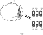
- FIG. 1 is a schematic diagram of a system to which this application is applied.
- the system 100 may include a network device 102 and terminal devices 104, 106, 108, 110, 112, and 114.
- the network device and the terminal devices are wirelessly connected to each other.
- FIG. 1 is described only by using an example in which the system includes one network device. However, this application is not limited thereto.
- the system may alternatively include more network devices.
- the system may alternatively include more terminal devices.
- the system may also be referred to as a network. This is not limited in this application.
- FIG. 2 is a schematic diagram of an example of a network architecture to which this application may be applied.
- the schematic diagram of the network architecture may be a diagram of a network architecture in NR in a next generation wireless communications system.
- a network device may be divided into a centralized unit (Centralized Unit, CU) and a plurality of transmission reception points (Transmission Reception Point, TRP)/distributed units (Distributed Unit, DU).
- TRP Transmission Reception Point
- DU Distribution Unit
- a bandwidth based unit (Bandwidth Based Unit, BBU) of the network device is reconstructed as DU and CU function entities.
- BBU bandwidth based unit
- a centralized unit 1 and TRPs/DUs in a dashed line range are composing elements of the network device 1
- a centralized unit 2 and TRPs/DUs in a solid line range are composing elements of the network device 2
- the network device 1 and the network device 2 are network devices (or referred to as base stations) in the NR system.
- the CU can process a radio upper-layer protocol stack function, for example, a radio resource control (Radio Resource Control, RRC) layer and a packet data convergence protocol (Packet Data Convergence Protocol, PDCP) layer, and can even support some core network functions in sinking to an access network.
- RRC Radio Resource Control
- PDCP Packet Data Convergence Protocol
- a network in which the core network functions sink to the access network is referred to as an edge computing network, to meet a higher network latency requirement of a future communications network for an emerging service such as video, online shopping, and virtual/augmented reality.
- the DU can mainly process a physical layer function and a layer 2 function with a relatively high real-time requirement.
- Radio Remote Unit Radio Remote Unit
- some physical layer functions of the DU may be moved up to the RRU.
- a more radical DU may be combined with the RRU.
- CUs can be deployed in a centralized manner. Deployment of DUs depends on an actual network environment. In an area with higher traffic density, a smaller inter-site distance, and limited equipment room resources, for example, a core urban area, a university, and a large-scale performance venue, DUs may also be deployed in a centralized manner.
- An S1-C interface shown in FIG. 2 may be a standard interface between a network device and a core network, and a specific device connected to the S1-C is not shown in FIG. 2 .
- the UE may be configured that UE performs mobility measurement by using a CSI-RS, and in addition, a sending time of the CSI-RS is associated with an on duration period of the UE, to reduce a possibility of measurement failure and reduce power consumption.
- the on duration period may be referred to as an on duration period, on duration, or an on period.
- the UE measures three cells (A/B/C), and the cell A is a serving cell (serving cell) of the UE.
- the cell A (or a network device, or a network device using the cell A) sends configuration information of CSI-RSs in the three cells to the UE, and the UE obtains the configuration information of the CSI-RSs in the three cells.
- the configuration information includes sending times of the CSI-RSs (namely, sending times of reference signals).
- the UE receives the CSI-RSs in the three cells at a corresponding sending time on a time frequency resource.
- the sending times of the CSI-RSs in the three cells are within the on duration period of the UE.
- the UE may be connected mode DRX UE (C-DRX UE).
- the following describes a specific solution for determining a sending time of a reference signal according to an on duration period.
- the determined sending time is sent to UE by using configuration information.
- a network device sends the reference signal at the sending time, and the UE receives the reference signal at the sending time.
- an on duration period of the UE and various cases in which the sending time is within the on duration period and the like are first described.
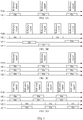
- FIG 3 is a schematic diagram of an on duration period of UE and a reference signal in this application.
- FIG. 3 shows an on duration period of at least one of all UEs that need to receive the reference signal, where on refers to an on duration period of each UE.
- FIG. 3A, FIG. 3B, FIG. 3C, and FIG. 3D are merely examples. It should be understood that more or fewer UEs may exist in this application.
- FIG. 3A shows an on duration period of one UE, namely, UE 1, in all the UEs that need to receive the reference signal.
- FIG. 3B shows on duration periods of three of all the UEs that need to receive the reference signal, where the on duration periods of UE 1, UE 2, and UE 3 are different.
- the three UEs may be all the UEs that need to receive the reference signal.
- FIG. 3C shows on duration periods of two of all the UEs that need to receive the reference signal, where the on duration periods of UE 1 and UE 2 are the same.
- only one reference signal may be configured in a same on duration period.
- FIG. 3D shows on duration periods of four of all the UEs that need to receive the reference signal, where on duration periods of UE 1 and UE 2 are the same, and on duration periods of UE 3 and UE 4 are the same.
- the UE 1 and the UE 2 may be considered as one group
- the UE 3 and the UE 4 may be considered as one group.
- a network device may perform grouping according to a preset rule.
- a specific grouping rule may be as follows: UEs whose on duration periods are the same or similar are classified into one group, UEs whose geographic locations are close are classified into one group, or UEs whose moving speeds are similar are classified into one group.
- FIG. 4A , FIG. 4B , FIG. 4C , and FIG. 4D are another schematic diagram of an on duration period of UE and a reference signal in this application.
- FIG. 4A , FIG. 4B , FIG. 4C , and FIG. 4D show an overlapping on duration period of at least two of all UEs that need to receive the reference signal, where on refers to an on duration period of each UE.
- FIG. 4A , FIG. 4B , FIG. 4C , and FIG. 4D are merely examples. It should be understood that more or fewer UEs may exist in this application.
- FIG. 4A shows an overlapping on duration period of two of all the UEs that need to receive the reference signal.
- FIG. 4C shows an overlapping on duration period of two of all the UEs that need to receive the reference signal, where on duration periods of UE 1 and UE 2 fully overlap.
- UEs whose on duration periods fully overlap may be considered as one group, and a grouping rule for the UEs is the same as that in the description in FIG. 3 .
- FIG. 4B shows overlapping on duration periods for three of all the UEs that need to receive the reference signal, where an overlapping on duration period includes an overlapping on duration period 1 of UE 1 and UE 2 and an overlapping on duration period 2 of the UE 2 and UE 3.
- the overlapping on duration period in this application may include either of the overlapping on duration period 1 and the overlapping on duration period 2, or both the overlapping on duration period 1 and the overlapping on duration period 2.
- FIG 4D shows an overlapping on duration period for three of all the UEs that need to receive the reference signal, where the overlapping on duration period may include an overlapping on duration period of two UEs, for example, either of an overlapping on duration period 1 and an overlapping on duration period 2, or an overlapping on duration period 3 of the three UEs. This is not limited in this application.
- FIG. 5 is a schematic diagram of a relationship between a sending time and an on duration period of UE.
- FIG. 5 shows an example of the relationship between the sending time and the on duration period only by using FIG. 3A as an example. It should be understood that the relationship between the sending time and the on duration period may include any one or more cases in FIG. 5 .
- the sending time is within the on duration period.
- the sending time partially overlaps with the on duration period.
- FIG. 5C the sending times and the on duration periods are regularly spaced. It should be understood that there may also be another relationship between the sending time and the on duration period.
- FIG. 5 is merely an example for description, and does not constitute a limitation.
- FIG. 6 is further refined according to FIG. 5A .
- FIG. 6 is a schematic diagram in which a sending time is within an on duration period. As shown in FIG. 6 , that the sending time is within the on duration period includes one or more of the following: FIG. 6A is a schematic diagram in which a start point of the sending time is the same as a start point of the on duration period; FIG. 6B is a schematic diagram in which an end point of the sending time is the same as an end point of the on duration period; and FIG. 6C is a schematic diagram in which a start point of the sending time is after a start point of the on duration period, and an end point of the sending time is before an end point of the on duration period.
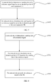
- FIG 7 is a schematic flowchart of determining a sending time according to an on duration period in this application. As shown in FIG. 7 , the method includes the following steps.
- a network device determines a sending time of a reference signal according to an on duration period of user equipment UE.
- a serving base station collects statistics on all UEs (the UEs may be DRX UEs, or further, connected mode DRX UEs) for which a CSI-RS needs to be configured, obtains an overlapping on duration period of at least two UEs through calculation according to DRX configurations of the UEs, and configures CSI-RS resources (sending times of reference signals) of a serving cell and a neighboring cell in the overlapping on duration period according to the overlapping on duration period of the UEs that is obtained through calculation.
- the UEs may be DRX UEs, or further, connected mode DRX UEs
- CSI-RS resources sending times of reference signals
- a serving base station collects statistics on all UEs for which a CSI-RS needs to be configured, groups the UEs according to DRX configurations of the UEs, obtains an overlapping on duration period of each group of UEs through calculation, and configures CSI-RS resources of a serving cell and a neighboring cell of the group of UEs in the overlapping on duration period according to the overlapping on duration period of the group of UEs that is obtained through calculation.
- a serving base station collects statistics on all UEs for which a CSI-RS needs to be configured, obtains on duration periods of all the UEs according to DRX configurations of the UEs through calculation, and configures CSI-RS resources of a serving cell and a neighboring cell in all the on duration periods according to the on duration periods of all the UEs that are obtained through calculation.
- S601 may include: The network device determines the sending time of the reference signal according to the on duration period and a time configuration information table of the reference signal.
- the time configuration information table of the CSI-RS is shown in Table 1.
- Time configuration information of the CSI-RS may be an intersection of a CSI-RS subframe configuration and an on duration period of UE.
- Table 1 CSI-RS-SubframeConfig I CSI-RS CSI-RS periodicity T CSI-RS (subframes) CSI-RS subframe offset ⁇ CSI-RS (subframes) 0 to 4 5 I CSI-RS 5 to 14 10 I CSI-RS -5 15 to 34 20 I CSI-RS -15 35 to 74 40 I CSI-RS -35 75 to 154 80 I CSI-RS -75
- the network device obtains an intersection of a sending time in the time configuration information table and the on duration period, and then selects the sending time of the reference signal from the intersection. If the intersection includes a plurality of sending times, the network device may select one or more sending times randomly, periodically, or by comprehensively considering another factor.
- the network device may be configured to send the CSI-RS in subframe 5 and/or 10.
- the network device sends the reference signal to the UE at the sending time.
- a relationship is established between the sending time of the reference signal and the on duration period of the UE, so that the reference signal is received in the on duration period of the UE as much as possible, to reduce a possibility of reception failure.
- the UE does not need to frequently wake up to receive the reference signal, to save power.
- a network device configures an on duration period of UE, and sends a configuration result to the UE. After receiving the information, the UE periodically wakes up according to the on duration period configured by the network device, and receives the reference signal at the sending time of the reference signal.
- the on duration period of the UE is first described.
- the on duration period is determined according to the sending time. Therefore, it is easily understood that the on duration period herein includes on duration periods of all UEs that need to receive the reference signal.
- the UEs may be grouped in this application.
- the on duration period is an on duration period of each UE in at least one group of UEs that need to receive the reference signal.
- FIG. 3 and FIG. 4A , FIG. 4B , FIG. 4C , and FIG. 4D For a specific relationship between the on duration period of the UE and the reference signal, refer to descriptions in FIG. 3 and FIG. 4A , FIG. 4B , FIG. 4C , and FIG. 4D .
- FIG. 8 is a schematic flowchart of a method for determining an on duration period according to a sending time in this application. As shown in FIG. 8 , the method includes the following steps. S701. A network device determines an on duration period of UE according to a sending time of a reference signal. For example, a serving network device may configure a DRX configuration parameter for each UE or a group of UEs, so that the on duration period includes the following CSI-RS measurement window.
- the method further includes the following step: S700.
- the network device determines the sending time of the reference signal.
- the serving base station may periodically configure CSI-RS resources of a serving cell and a neighboring cell of each UE or a group of UEs in the CSI-RS measurement window.
- the network device sends the reference signal to the UE.
- the network device sends the reference signal to the UE at the sending time.
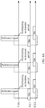
- FIG. 9 is a schematic structural diagram of a device 100 in this application.
- the device 100 may be applied to a network device or UE that implements this application. Referring to FIG. 9 , the device 100 includes a receiving unit 101, a sending unit 102, and a processing unit 103.
- the processing unit 103 is configured to determine a sending time of a reference signal according to an on duration period of the user equipment UE, or configured to determine an on duration period of the UE according to a sending time of a reference signal.
- the sending unit 102 is configured to send the reference signal to the UE.
- the receiving unit 101 is configured to: receive configuration information of an on duration period from the network device; and receive, in the on duration period, a reference signal from the network device. It should be understood that with reference to any one or more of the foregoing methods, the network device and the UE may further include more function units for implementing more functions, to associate the sending time with the on duration period, reduce power consumption, and reduce a possibility of reception failure.
- the receiving unit may be implemented by using a communications interface, a receiver, a receiving circuit, or the like.
- the sending unit may be implemented by using a communications interface, a transmitter, a sending circuit, or the like. It should be understood that functions of the receiving unit and the sending unit may also be integrated together and implemented by a communications interface, a transceiver, and a transceiver circuit.
- the communications interface is a general term, and may include one or more interfaces.
- hardware for implementing the network device or the UE is not limited to the foregoing structure, for example, may further include a processor, a memory, an antenna array, a duplexer, and a baseband processing part.
- the processor may be a central processing unit (Central Processing Unit, CPU), a general purpose processor, a digital signal processor (Digital Signal Processor, DSP), an application-specific integrated circuit (Application-Specific Integrated Circuit, ASIC), a field programmable gate array (Field Programmable Gate Array, FPGA) or another programmable logic device, a hardware component, or any combination thereof.
- CPU Central Processing Unit
- DSP digital signal processor
- ASIC Application-Specific Integrated Circuit
- FPGA Field Programmable Gate Array
- the processor may be a combination of processors implementing a computing function, for example, a combination of one or more microprocessors or a combination of a DSP and a microprocessor.
- the memory may be disposed in the processor, or may independently exist.
- the duplexer is configured to implement the antenna array and is configured to send and receive signals.
- the transmitter is configured to implement conversion between a radio frequency signal and a baseband signal.
- the transmitter may usually include a power amplifier, a digital-to-analog converter, and a frequency converter.
- the receiver may usually include a low noise amplifier, an analog-to-digital converter, and a frequency converter.
- the receiver and the transmitter may also be collectively referred to as a transceiver sometimes.
- the baseband processing part is configured to: process a sent or received signal, for example, layer mapping, precoding, modulation/demodulation, and encoding/decoding, and separately process a physical control channel, a physical data channel, a physical broadcast channel, a reference signal, and the like.
- functions of the receiver and the transmitter may be implemented by using a transceiver circuit or a dedicated transceiver chip.
- the processor may be implemented by using a dedicated processing chip, a processing circuit, a processor, or a general-purpose chip.
- program code used to implement functions of the processor, the receiver, and the transmitter is stored in the memory.
- the general purpose processor implements the functions of the processor, the receiver, and the transmitter by executing the code in the memory.
- a network device 1000 is provided, and includes a processor 1001, a memory 1004, a receiver 1003, and a transmitter 1002.
- the receiver 1003 and the transmitter 1002 are configured to communicate with another network element.
- the memory 1004 is configured to store a program that can be executed by the processor 1001.
- the program includes an instruction used to implement the methods, the steps, or the procedures described in the foregoing embodiments. For a specific method, procedure, step, beneficial effect, and the like, refer to descriptions about the content in the foregoing embodiments. Details are not described herein again.
- UE 2000 is provided, and includes a processor 2001, a memory 2003, and a transceiver 2002.
- the transceiver 2002 is configured to communicate with another network element (may communicate with the another network element by using an antenna).
- the memory 2003 is configured to store a program that can be executed by the processor 2001.
- the program includes an instruction used to implement the methods, the steps, or the procedures described in the foregoing embodiments. For a specific method, procedure, step, beneficial effect, and the like, refer to descriptions about the content in the foregoing embodiments. Details are not described herein again.
- the network device or the UE When the network device or the UE is implemented by using software, for a concept, explanation, detailed description, and another step that are related to this application and that are used in the network device or the UE, reference may be made to descriptions about the content in the foregoing methods.
- some or all of the methods may be implemented in a form of a computer program product.
- the computer program product includes one or more computer instructions. When the computer program instructions are loaded and executed on a computer, some or all of the procedures or functions in this application are generated.
- the computer may be a general-purpose computer, a dedicated computer, a computer network, or another programmable apparatus.
- the computer instructions may be stored in a computer readable storage medium or may be transmitted from a computer readable storage medium to another computer readable storage medium.
- the computer instructions may be transmitted from a website, computer, server, or data center to another website, computer, server, or data center in a wired (for example, a coaxial cable, an optical fiber, or a digital subscriber line (DSL)) or wireless (for example, infrared, radio, or microwave) manner.
- the computer readable storage medium may be any usable medium accessible by the computer, or a data storage device, such as a server or a data center, integrating one or more usable media.
- the usable medium may be a magnetic medium (for example, a floppy disk, a hard disk, or a magnetic tape), an optical medium (for example, a DVD), a semi-conductor medium (for example, a solid state disk Solid State Disk (SSD)), or the like.
- the storage medium may be integrated in a device, a module, or a processor, or may be separately disposed.
- this application further provides a communications system, and the communications system includes the foregoing network device and UE.
Landscapes
- Engineering & Computer Science (AREA)
- Signal Processing (AREA)
- Computer Networks & Wireless Communication (AREA)
- Mobile Radio Communication Systems (AREA)
Applications Claiming Priority (2)
| Application Number | Priority Date | Filing Date | Title |
|---|---|---|---|
| CN201710682218.3A CN109547174B (zh) | 2017-08-10 | 2017-08-10 | 一种时间配置的方法、网络设备及ue |
| PCT/CN2018/098902 WO2019029466A1 (fr) | 2017-08-10 | 2018-08-06 | Procédé d'attribution de temps, dispositif de réseau et ue |
Publications (2)
| Publication Number | Publication Date |
|---|---|
| EP3661099A1 true EP3661099A1 (fr) | 2020-06-03 |
| EP3661099A4 EP3661099A4 (fr) | 2020-08-05 |
Family
ID=65270922
Family Applications (1)
| Application Number | Title | Priority Date | Filing Date |
|---|---|---|---|
| EP18845268.4A Pending EP3661099A4 (fr) | 2017-08-10 | 2018-08-06 | Procédé d'attribution de temps, dispositif de réseau et ue |
Country Status (4)
| Country | Link |
|---|---|
| US (1) | US11388778B2 (fr) |
| EP (1) | EP3661099A4 (fr) |
| CN (1) | CN109547174B (fr) |
| WO (1) | WO2019029466A1 (fr) |
Cited By (1)
| Publication number | Priority date | Publication date | Assignee | Title |
|---|---|---|---|---|
| WO2021011112A1 (fr) * | 2019-07-12 | 2021-01-21 | Qualcomm Incorporated | Signalisation de réveil de groupe pour découverte de nœuds relais par ondes millimétriques |
Families Citing this family (9)
| Publication number | Priority date | Publication date | Assignee | Title |
|---|---|---|---|---|
| US10743208B2 (en) * | 2018-03-12 | 2020-08-11 | Apple Inc. | Power saving for channel state information reference signal reception |
| CN112188609B (zh) * | 2019-07-04 | 2021-11-19 | 华为技术有限公司 | 确定定时提前ta参考时刻的方法和装置 |
| US11558162B2 (en) | 2019-08-12 | 2023-01-17 | Qualcomm Incorporated | Interaction of discontinuous reception (DRX) with positioning reference signal (PRS) resources |
| CN112399498B (zh) | 2019-08-15 | 2021-09-07 | 华为技术有限公司 | 用于小区测量的方法和装置 |
| CN112399439B (zh) * | 2019-08-16 | 2022-05-31 | 华为技术有限公司 | 一种信号传输的方法、终端设备以及网络设备 |
| US11863488B2 (en) * | 2020-04-27 | 2024-01-02 | Qualcomm Incorporated | Single reference signal timing information for measurements of multiple reference signals of multiple cells |
| CN115699901A (zh) | 2020-09-23 | 2023-02-03 | Oppo广东移动通信有限公司 | 一种资源指示方法、电子设备及存储介质 |
| CN115280708B (zh) * | 2021-12-23 | 2024-07-05 | 上海移远通信技术股份有限公司 | 无线通信的方法和通信装置 |
| CN114339867B (zh) * | 2021-12-31 | 2024-03-19 | 哲库科技(北京)有限公司 | 小区测量方法、装置、终端设备及存储介质 |
Family Cites Families (24)
| Publication number | Priority date | Publication date | Assignee | Title |
|---|---|---|---|---|
| MX2010006988A (es) * | 2007-12-21 | 2010-08-12 | Research In Motion Ltd | Sistema y metodo para utilizacion de recursos de enlace ascendente. |
| US20100208660A1 (en) * | 2009-02-19 | 2010-08-19 | Samsung Electronics Co., Ltd. | Method for distributed drx operation for ease of scheduling and effective power saving |
| JP5205320B2 (ja) * | 2009-03-25 | 2013-06-05 | 株式会社エヌ・ティ・ティ・ドコモ | 無線基地局及び移動通信方法 |
| EP2556718B1 (fr) * | 2010-04-06 | 2020-06-03 | Telefonaktiebolaget LM Ericsson (publ) | Procédés et agencements pour des réseaux sans fil ad hoc |
| EP2670199A1 (fr) * | 2011-01-25 | 2013-12-04 | Fujitsu Limited | Dispositif de station de base sans fil, système de communication sans fil, procédé de communication sans fil pour dispositif de station de base sans fil et dispositif terminal |
| US8837313B2 (en) * | 2011-04-04 | 2014-09-16 | Kyocera Corporation | Mobile communication method and radio terminal |
| CN102257859B (zh) * | 2011-06-01 | 2013-08-07 | 华为技术有限公司 | 混合非连续接收方法及基站和用户设备 |
| US8995385B2 (en) * | 2011-08-05 | 2015-03-31 | Samsung Electronics Co., Ltd. | Apparatus and method for UE-specific demodulation reference signal scrambling |
| US9198071B2 (en) * | 2012-03-19 | 2015-11-24 | Qualcomm Incorporated | Channel state information reference signal configuring and reporting for a coordinated multi-point transmission scheme |
| US9264997B2 (en) * | 2012-07-03 | 2016-02-16 | Qualcomm Incorporated | Apparatus and methods of energy efficient communication |
| WO2014149062A1 (fr) * | 2013-03-22 | 2014-09-25 | Hitachi, Ltd. | Procédé et appareil pour configurer un signal de référence de démodulation dans des réseaux lte avancés |
| US9713117B2 (en) * | 2014-09-25 | 2017-07-18 | Intel Corporation | Device-to-device assisted positioning in wireless cellular technologies |
| US9872335B2 (en) * | 2015-03-06 | 2018-01-16 | Marvell International Ltd. | Iterative receiver wake-up for long DRX periods |
| WO2017097567A1 (fr) * | 2015-12-10 | 2017-06-15 | Nokia Solutions And Networks Oy | Communication d'une signalisation d'informations de commande pendant une réception discontinue (drx) sur un spectre sans licence |
| CN108476110B (zh) * | 2015-12-31 | 2021-10-08 | Idac控股公司 | 用于动态管理参考信号的方法 |
| US10187191B2 (en) * | 2016-01-27 | 2019-01-22 | Qualcomm Incorporated | SRS transmission in management in carrier aggregation |
| US10224994B2 (en) * | 2016-02-26 | 2019-03-05 | Samsung Electronics Co., Ltd. | System and method of connected mode discontinuous operation in beamformed system |
| US10506578B2 (en) * | 2017-04-21 | 2019-12-10 | Apple Inc. | Hybrid multi-sync-signal for wideband NR carrier |
| US11088769B2 (en) * | 2017-08-18 | 2021-08-10 | Qualcomm Incorporated | Radio link monitoring based on multiple reference signals |
| US10750444B2 (en) * | 2017-08-18 | 2020-08-18 | Qualcomm Incorporated | Advanced grant indicator and aperiodic tracking reference signal in discontinuous reception |
| CN111052839B (zh) * | 2017-08-31 | 2022-11-25 | 中兴通讯股份有限公司 | 连接不连续接收中的波束恢复 |
| US11297674B2 (en) * | 2018-02-14 | 2022-04-05 | Samsung Electronics Co., Ltd. | Method and apparatus for power savings at a user equipment |
| US10652826B2 (en) * | 2018-03-23 | 2020-05-12 | Samsung Electronics Co., Ltd. | Method and apparatus for power saving signal design in NR |
| US11224088B2 (en) * | 2018-07-02 | 2022-01-11 | Qualcomm Incorporated | Beam sweeping during an on-period of a DRX cycle |
-
2017
- 2017-08-10 CN CN201710682218.3A patent/CN109547174B/zh active Active
-
2018
- 2018-08-06 EP EP18845268.4A patent/EP3661099A4/fr active Pending
- 2018-08-06 WO PCT/CN2018/098902 patent/WO2019029466A1/fr unknown
-
2020
- 2020-02-07 US US16/784,628 patent/US11388778B2/en active Active
Cited By (2)
| Publication number | Priority date | Publication date | Assignee | Title |
|---|---|---|---|---|
| WO2021011112A1 (fr) * | 2019-07-12 | 2021-01-21 | Qualcomm Incorporated | Signalisation de réveil de groupe pour découverte de nœuds relais par ondes millimétriques |
| US11160021B2 (en) | 2019-07-12 | 2021-10-26 | Qualcomm Incorporated | Group wake up signaling for millimeter wave relay node discovery |
Also Published As
| Publication number | Publication date |
|---|---|
| WO2019029466A1 (fr) | 2019-02-14 |
| CN109547174A (zh) | 2019-03-29 |
| EP3661099A4 (fr) | 2020-08-05 |
| US11388778B2 (en) | 2022-07-12 |
| CN109547174B (zh) | 2022-05-24 |
| US20200214082A1 (en) | 2020-07-02 |
Similar Documents
| Publication | Publication Date | Title |
|---|---|---|
| US11388778B2 (en) | Time configuration method, network device, and UE | |
| US9693304B2 (en) | Rescheduling of a resource component of low power nodes (LPNs) in a coordination set | |
| EP3641202B1 (fr) | Procédés et dispositifs de transmission et de réception d'informations de commande de liaison descendante | |
| US11240769B2 (en) | System information for narrowband | |
| WO2020221318A1 (fr) | Procédé et appareil de gestion de faisceaux de liaison montante | |
| US11653369B2 (en) | Explicit configuration of paging and control channel in system information | |
| JP2021520105A (ja) | 通信システムにおける時間ドメイン割り当てを提供するためのシステムおよび方法 | |
| EP4027743A1 (fr) | Procédé et appareil de transmission de données | |
| WO2015100595A1 (fr) | Procédé, dispositif, et système de communication | |
| WO2019015445A1 (fr) | Procédé de communication et appareil | |
| WO2014206201A1 (fr) | Procédé de réseautage centralisé et dispositif terminal | |
| CN103873218A (zh) | 公共搜索空间css的干扰协调方法及装置 | |
| EP3282743B1 (fr) | Procédé et dispositif d'envoi de signal | |
| JP6518267B2 (ja) | 端末装置および端末装置によって実行される方法 | |
| WO2023159472A1 (fr) | Procédé de communication et dispositif terminal | |
| CN112333811B (zh) | 一种同步信号/物理广播信道块发送功率配置方法及装置 | |
| WO2024032208A1 (fr) | Procédé et appareil de communication | |
| WO2024148617A1 (fr) | Procédé de communication sans fil, dispositif terminal et périphérique de réseau | |
| WO2024120176A1 (fr) | Procédé, appareil et système de communication | |
| WO2024031533A1 (fr) | Procédé de positionnement en liaison latérale, dispositif terminal et dispositif de réseau | |
| WO2024041333A1 (fr) | Procédé et appareil de collecte d'énergie | |
| WO2024152197A1 (fr) | Procédé de transmission de liaison latérale et dispositif terminal | |
| US20240314882A1 (en) | Communication method, terminal device, and network device | |
| US20240155642A1 (en) | Frequency domain resource set indication for redcap ue | |
| WO2024016238A1 (fr) | Procédés et appareils de communication sans fil |
Legal Events
| Date | Code | Title | Description |
|---|---|---|---|
| STAA | Information on the status of an ep patent application or granted ep patent |
Free format text: STATUS: THE INTERNATIONAL PUBLICATION HAS BEEN MADE |
|
| PUAI | Public reference made under article 153(3) epc to a published international application that has entered the european phase |
Free format text: ORIGINAL CODE: 0009012 |
|
| STAA | Information on the status of an ep patent application or granted ep patent |
Free format text: STATUS: REQUEST FOR EXAMINATION WAS MADE |
|
| 17P | Request for examination filed |
Effective date: 20200225 |
|
| AK | Designated contracting states |
Kind code of ref document: A1 Designated state(s): AL AT BE BG CH CY CZ DE DK EE ES FI FR GB GR HR HU IE IS IT LI LT LU LV MC MK MT NL NO PL PT RO RS SE SI SK SM TR |
|
| AX | Request for extension of the european patent |
Extension state: BA ME |
|
| A4 | Supplementary search report drawn up and despatched |
Effective date: 20200706 |
|
| RIC1 | Information provided on ipc code assigned before grant |
Ipc: H04L 5/00 20060101AFI20200630BHEP Ipc: H04W 52/02 20090101ALI20200630BHEP |
|
| DAV | Request for validation of the european patent (deleted) | ||
| DAX | Request for extension of the european patent (deleted) | ||
| STAA | Information on the status of an ep patent application or granted ep patent |
Free format text: STATUS: EXAMINATION IS IN PROGRESS |
|
| 17Q | First examination report despatched |
Effective date: 20210817 |