EP3661031A1 - Improved electric motor for washing machines - Google Patents
Improved electric motor for washing machines Download PDFInfo
- Publication number
- EP3661031A1 EP3661031A1 EP19209588.3A EP19209588A EP3661031A1 EP 3661031 A1 EP3661031 A1 EP 3661031A1 EP 19209588 A EP19209588 A EP 19209588A EP 3661031 A1 EP3661031 A1 EP 3661031A1
- Authority
- EP
- European Patent Office
- Prior art keywords
- shield
- electric motor
- assembly
- motor
- stator
- Prior art date
- Legal status (The legal status is an assumption and is not a legal conclusion. Google has not performed a legal analysis and makes no representation as to the accuracy of the status listed.)
- Pending
Links
Images


Classifications
-
- H—ELECTRICITY
- H02—GENERATION; CONVERSION OR DISTRIBUTION OF ELECTRIC POWER
- H02K—DYNAMO-ELECTRIC MACHINES
- H02K5/00—Casings; Enclosures; Supports
- H02K5/04—Casings or enclosures characterised by the shape, form or construction thereof
-
- H—ELECTRICITY
- H02—GENERATION; CONVERSION OR DISTRIBUTION OF ELECTRIC POWER
- H02K—DYNAMO-ELECTRIC MACHINES
- H02K15/00—Methods or apparatus specially adapted for manufacturing, assembling, maintaining or repairing of dynamo-electric machines
- H02K15/16—Centering rotors within the stator; Balancing rotors
-
- H—ELECTRICITY
- H02—GENERATION; CONVERSION OR DISTRIBUTION OF ELECTRIC POWER
- H02K—DYNAMO-ELECTRIC MACHINES
- H02K15/00—Methods or apparatus specially adapted for manufacturing, assembling, maintaining or repairing of dynamo-electric machines
- H02K15/14—Casings; Enclosures; Supports
-
- H—ELECTRICITY
- H02—GENERATION; CONVERSION OR DISTRIBUTION OF ELECTRIC POWER
- H02K—DYNAMO-ELECTRIC MACHINES
- H02K5/00—Casings; Enclosures; Supports
- H02K5/04—Casings or enclosures characterised by the shape, form or construction thereof
- H02K5/06—Cast metal casings
-
- H—ELECTRICITY
- H02—GENERATION; CONVERSION OR DISTRIBUTION OF ELECTRIC POWER
- H02K—DYNAMO-ELECTRIC MACHINES
- H02K5/00—Casings; Enclosures; Supports
- H02K5/04—Casings or enclosures characterised by the shape, form or construction thereof
- H02K5/15—Mounting arrangements for bearing-shields or end plates
-
- H—ELECTRICITY
- H02—GENERATION; CONVERSION OR DISTRIBUTION OF ELECTRIC POWER
- H02K—DYNAMO-ELECTRIC MACHINES
- H02K5/00—Casings; Enclosures; Supports
- H02K5/04—Casings or enclosures characterised by the shape, form or construction thereof
- H02K5/16—Means for supporting bearings, e.g. insulating supports or means for fitting bearings in the bearing-shields
- H02K5/161—Means for supporting bearings, e.g. insulating supports or means for fitting bearings in the bearing-shields radially supporting the rotary shaft at both ends of the rotor
-
- H—ELECTRICITY
- H02—GENERATION; CONVERSION OR DISTRIBUTION OF ELECTRIC POWER
- H02K—DYNAMO-ELECTRIC MACHINES
- H02K5/00—Casings; Enclosures; Supports
- H02K5/04—Casings or enclosures characterised by the shape, form or construction thereof
- H02K5/16—Means for supporting bearings, e.g. insulating supports or means for fitting bearings in the bearing-shields
- H02K5/173—Means for supporting bearings, e.g. insulating supports or means for fitting bearings in the bearing-shields using bearings with rolling contact, e.g. ball bearings
- H02K5/1732—Means for supporting bearings, e.g. insulating supports or means for fitting bearings in the bearing-shields using bearings with rolling contact, e.g. ball bearings radially supporting the rotary shaft at both ends of the rotor
-
- H—ELECTRICITY
- H02—GENERATION; CONVERSION OR DISTRIBUTION OF ELECTRIC POWER
- H02K—DYNAMO-ELECTRIC MACHINES
- H02K5/00—Casings; Enclosures; Supports
- H02K5/24—Casings; Enclosures; Supports specially adapted for suppression or reduction of noise or vibrations
Definitions
- the present invention refers to an improved brushless permanent magnet electric motor, which is intended to be used to rotate the drum of a washing machine.
- the improvement concerns in particular the shields, or caps, wherein the stator and rotor assemblies are enclosed, forming the constructive mechanical structure of the motor.
- Brushless permanent magnet electric motors for washing machines substantially consist of a stator and a rotor, each of which is made up of a stack of magnetic laminations.
- the stator is provided with windings that generate the magnetic field, while in the rotor a shaft is inserted that is supported at its ends by respective bearings.
- the bearings are housed in their respective shields, or caps, which completely enclose the motor.
- the shields are generally obtained by die-casting in aluminum alloy. Subsequently, both shields are machined by chip removal in some of their parts to produce surfaces and references with adequate tolerances to ensure the necessary precision in assembly. In effect, when the motor is finished, the precision of the coupling and the perfect operation of the components must be guaranteed.
- the parts of the shields that are machined are: the housing seats of the bearings, the support base of the stator, and the reference surfaces for centering the stator on the motor axis.
- the motor may be mounted manually, semi-automatically or automatically.
- the process involves: the assembly of the two shields, front and rear, with the stator; the insertion of the rotor, already pre-assembled, balanced and pre-magnetized; the tightening of the rotor assembly and the stator assembly by means of screws.
- the assembly operation is carried out automatically, as is increasingly the case, a specific machine is used, which aligns the various components, front shield, stator assembly, rotor assembly, and rear shield. Also in this case, however, the alignment that is obtained may not be optimal, because at least one of the two shields is positioned in the machine in reference to the outer surface of the shield, which cannot offer precise abutment zones, being a rough product of die-casting.
- the present invention proposes the object of overcoming the aforementioned problems by obtaining on the outer surface of at least one of the two shields of the motor an abutment zone that is precision machined so as to allow it to be taken as an exact reference for the positioning and centering of the components in the assembly process of the motor.
- the most suitable outer surface to meet the needs of the required machining is the outer ring of the bearing housing. In effect, this surface is easily accessible and workable with common machine tools, without requiring tools or work cycles significantly different from the traditional ones. Moreover, this surface does not require any significant changes in the design of the rough shield and in the manufacture of the die-casting molds. Finally, the bearing zone is one of the few "invariants" available, being the same for all motor configurations.
- the predefined object is achieved with a motor according to the invention, the technical characteristics of which are defined in the claims of the present patent.
- a BPM motor 1 is substantially composed of: a stator 10; in which a rotor 12 is inserted, provided with a shaft 14 that penetrates it axially; a first shield 16, mounted on one end of the shaft 14; and a second shield 18, mounted on the opposite end of the shaft 14.
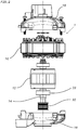
- Fig. 2 shows the motor (1) in exploded view in the assembly stage, arranged with the axis of rotation in the vertical direction and with the shields open, i.e. apart from each other.
- the stator 10 is made up of a stack of magnetic laminations, and is equipped with windings (not shown) that generate the variable magnetic field.
- the rotor 12 is supported by the shaft 14 by means of a first bearing 20 and a second bearing 22, housed in their respective shields 16 and 18.
- the shield 16 is provided centrally with a ring 24 provided with an axial opening through which one end of the shaft 14 passes.
- the shield 18 is provided with a ring 26 provided with an axial opening through which the other end of the shaft 14 passes.
- the ring 24 extends inside the shield 16 to form a seat 28 in which the first bearing 20 is housed.
- the machining accuracy of the inner surface of the seat 28 of the bearing 20 is sufficient to ensure the correct axial alignment between the shield 16 and the axis of the rotor 12.
- the ring 26 extends inside the shield 18 to form a seat 30 in which the second bearing 22 is housed.
- the shaft 14, when the motor 1 is assembled, extends outside the shield 18 to support a pulley 32, on which a belt (not shown) runs that transmits the rotation to the drum of the washing machine (not shown) for which the motor is used according to the invention.
- the essential characteristic of the present invention is represented in that an outer cylindrical surface 40 of the seat 30 of the bearing 22 housed in the shield 18, at the end of the shaft 14 that supports the pulley, is subjected to precision machining, such as turning, milling or the like, in order to be able to carry out the function of centering the components of the motor.
- This machining is particularly advantageous when it is carried out simultaneously with the machining of the inner surface of the seat 30 of the bearing 20. In effect, performing these processes simultaneously ensures the concentricity of the outer cylindrical surface 40 with the seat 30 of the bearing.
- Fig. 3 is a perspective view from the inside of the shield 18 of the motor 1 according to the invention.
- the shield 18 has a preferably square shape and it is recalled that, normally, the inner surface of the seat 30 of the bearing 22 is bored with a preferably circular section.
- the square shape of shield 18 allows one to obtain at the four corners of the shield the same number of support and closure surfaces S of the stator.
- Fig. 4 is a perspective view from the outside of the shield 18 of the motor according to the invention.
- the shield 18 has a preferably square shape and is substantially analogous to the shield 16.
- the shield 18 is provided with a ring 26, formed by an axial opening, through which one end of the shaft 14 passes.
- the cylindrical outer surface 40 of the ring 26, which projects out of the shield 18, is subjected to precision machining, such as turning, milling or the like.
- This surface 40 is easily accessible and workable with common machine tools, without requiring tools or work cycles significantly different from the traditional ones.
- this surface does not require any significant changes in the design of the rough shield and in the manufacture of the die-casting molds.
- the bearing zone is one of the few "invariants" available, being the same for all motor configurations.
- the manufacturing process of the electric motor 1 comprises the steps of: assembling the stator 10 assembly consisting of a stack of magnetic laminations and provided with windings that generate a magnetic field; assembling the rotor 12 assembly in which the driving shaft 14 is inserted and which rotates axially inside the stator and the bearings 20 and 22; inserting vertically the first and the second shield 16, 18, obtained by die-casting in aluminum, in the respective bearings opposite to the two ends of the driving shaft, so as to enclose between them the stator assembly 10 and the rotor assembly 12; aligning and centering of the rotor axis with the stator axis by means of a device with self-centering jaws (known per se and not shown).
- At least one of the first shield and the second shield 16, 18 is mechanically machined first, by milling, turning or the like, on at least one outer surface 40 thereof to create a precise reference area so as to allow the same shield to be centered with reference to at least one of the geometric axes thereof.
- said previously machined outer surface 40 of said one of the first and second shield is the cylindrical outer surface of the bearing seat, projecting axially out of the shield.
- said previously machined surface may be the surface 41 of the molding impression on the outer surface of the shield.
- the prior machining of the outer reference surface is carried out simultaneously with the boring of the bearing seat in the respective shield.
Landscapes
- Engineering & Computer Science (AREA)
- Power Engineering (AREA)
- Manufacturing & Machinery (AREA)
- Motor Or Generator Frames (AREA)
- Detergent Compositions (AREA)
- Iron Core Of Rotating Electric Machines (AREA)
Abstract
Description
- . The present invention refers to an improved brushless permanent magnet electric motor, which is intended to be used to rotate the drum of a washing machine. The improvement concerns in particular the shields, or caps, wherein the stator and rotor assemblies are enclosed, forming the constructive mechanical structure of the motor.
- . Brushless permanent magnet electric motors for washing machines substantially consist of a stator and a rotor, each of which is made up of a stack of magnetic laminations. The stator is provided with windings that generate the magnetic field, while in the rotor a shaft is inserted that is supported at its ends by respective bearings. The bearings are housed in their respective shields, or caps, which completely enclose the motor.
- . The shields are generally obtained by die-casting in aluminum alloy. Subsequently, both shields are machined by chip removal in some of their parts to produce surfaces and references with adequate tolerances to ensure the necessary precision in assembly. In effect, when the motor is finished, the precision of the coupling and the perfect operation of the components must be guaranteed. Normally, the parts of the shields that are machined are: the housing seats of the bearings, the support base of the stator, and the reference surfaces for centering the stator on the motor axis.
The motor may be mounted manually, semi-automatically or automatically. The process involves: the assembly of the two shields, front and rear, with the stator; the insertion of the rotor, already pre-assembled, balanced and pre-magnetized; the tightening of the rotor assembly and the stator assembly by means of screws. - . The assembly operation of the motor, when carried out manually, requires a great deal of manual skill on the part of the operator, especially in the case of a BPM (brushless permanent magnet) motor, with pre-magnetized rotor, wherein the rotor attracting the stator tends naturally to misalign the components.
- . When, on the other hand, the assembly operation is carried out automatically, as is increasingly the case, a specific machine is used, which aligns the various components, front shield, stator assembly, rotor assembly, and rear shield.
Also in this case, however, the alignment that is obtained may not be optimal, because at least one of the two shields is positioned in the machine in reference to the outer surface of the shield, which cannot offer precise abutment zones, being a rough product of die-casting. - . Consequently, clearances in the assembly stations and coupling tolerances which are large enough to compensate for the inevitable imprecision of the alignments must be provided. This increase in clearances and tolerances clearly translates into greater variability and dispersion of the functional characteristics of the motor, in terms of both performance and noise.
The resulting problems are particularly annoying when the motor is applied to a domestic washing machine. In effect, the user must accept an increase in electrical consumption and, above all, in noise, since modern washing machines tend to continuously increase in speed of rotation of the drum in the spin cycle. - . The present invention proposes the object of overcoming the aforementioned problems by obtaining on the outer surface of at least one of the two shields of the motor an abutment zone that is precision machined so as to allow it to be taken as an exact reference for the positioning and centering of the components in the assembly process of the motor.
- . The most suitable outer surface to meet the needs of the required machining is the outer ring of the bearing housing. In effect, this surface is easily accessible and workable with common machine tools, without requiring tools or work cycles significantly different from the traditional ones. Moreover, this surface does not require any significant changes in the design of the rough shield and in the manufacture of the die-casting molds. Finally, the bearing zone is one of the few "invariants" available, being the same for all motor configurations.
- . The predefined object is achieved with a motor according to the invention, the technical characteristics of which are defined in the claims of the present patent.
- . The characteristics and advantages of the motor, according to the present invention, will become more evident in the following description given by way of nonlimiting example with reference to the accompanying figures wherein:
-
Fig. 1 is a sectional view showing a BPM (brushless permanent magnet) motor for a washing machine, according to the invention; -
Fig. 2 is an exploded view of the motor ofFig. 1 , during the assembly stage; -
Fig. 3 is a perspective view from within one of the shields of the motor ofFig.1 , -
Fig. 4 is a perspective view from the outside of the shield ofFig. 3 . - . As may be seen in
Fig. 1 , aBPM motor 1 is substantially composed of: astator 10; in which arotor 12 is inserted, provided with ashaft 14 that penetrates it axially; afirst shield 16, mounted on one end of theshaft 14; and asecond shield 18, mounted on the opposite end of theshaft 14.Fig. 2 shows the motor (1) in exploded view in the assembly stage, arranged with the axis of rotation in the vertical direction and with the shields open, i.e. apart from each other.
Thestator 10 is made up of a stack of magnetic laminations, and is equipped with windings (not shown) that generate the variable magnetic field. Therotor 12 is supported by theshaft 14 by means of a first bearing 20 and a second bearing 22, housed in theirrespective shields - . The
shield 16 is provided centrally with aring 24 provided with an axial opening through which one end of theshaft 14 passes. Similarly, theshield 18 is provided with aring 26 provided with an axial opening through which the other end of theshaft 14 passes. - . The
ring 24 extends inside theshield 16 to form aseat 28 in which the first bearing 20 is housed. The machining accuracy of the inner surface of theseat 28 of thebearing 20 is sufficient to ensure the correct axial alignment between theshield 16 and the axis of therotor 12.
Similarly, thering 26 extends inside theshield 18 to form aseat 30 in which the second bearing 22 is housed. Theshaft 14, when themotor 1 is assembled, extends outside theshield 18 to support apulley 32, on which a belt (not shown) runs that transmits the rotation to the drum of the washing machine (not shown) for which the motor is used according to the invention. - . The essential characteristic of the present invention is represented in that an outer
cylindrical surface 40 of theseat 30 of thebearing 22 housed in theshield 18, at the end of theshaft 14 that supports the pulley, is subjected to precision machining, such as turning, milling or the like, in order to be able to carry out the function of centering the components of the motor. This machining is particularly advantageous when it is carried out simultaneously with the machining of the inner surface of theseat 30 of thebearing 20. In effect, performing these processes simultaneously ensures the concentricity of the outercylindrical surface 40 with theseat 30 of the bearing. - .
Fig. 3 is a perspective view from the inside of theshield 18 of themotor 1 according to the invention. As may be noted, theshield 18 has a preferably square shape and it is recalled that, normally, the inner surface of theseat 30 of thebearing 22 is bored with a preferably circular section. The square shape ofshield 18 allows one to obtain at the four corners of the shield the same number of support and closure surfaces S of the stator. - .
Fig. 4 is a perspective view from the outside of theshield 18 of the motor according to the invention. As may be seen, also theshield 18 has a preferably square shape and is substantially analogous to theshield 16. As mentioned previously, theshield 18 is provided with aring 26, formed by an axial opening, through which one end of theshaft 14 passes. According to the present invention, the cylindricalouter surface 40 of thering 26, which projects out of theshield 18, is subjected to precision machining, such as turning, milling or the like.
Thissurface 40 is easily accessible and workable with common machine tools, without requiring tools or work cycles significantly different from the traditional ones. Moreover, this surface does not require any significant changes in the design of the rough shield and in the manufacture of the die-casting molds. Finally, the bearing zone is one of the few "invariants" available, being the same for all motor configurations. - . Naturally, other surfaces could also, in principle, be used to achieve precise control of the relative angular position between the shield and stator. For example, one could for this purpose machine the "guard" surface 41 (
Fig. 4 ), that is to say the annular surface of theshield 18 that externally surrounds thering 26.
If one wishes to obtain an even more precise result, one could machine bothsurfaces - . The manufacturing process of the
electric motor 1 comprises the steps of: assembling thestator 10 assembly consisting of a stack of magnetic laminations and provided with windings that generate a magnetic field; assembling therotor 12 assembly in which the drivingshaft 14 is inserted and which rotates axially inside the stator and thebearings second shield stator assembly 10 and therotor assembly 12; aligning and centering of the rotor axis with the stator axis by means of a device with self-centering jaws (known per se and not shown). - . According to the invention, at least one of the first shield and the
second shield outer surface 40 thereof to create a precise reference area so as to allow the same shield to be centered with reference to at least one of the geometric axes thereof. Preferably, said previously machinedouter surface 40 of said one of the first and second shield is the cylindrical outer surface of the bearing seat, projecting axially out of the shield. - . Alternatively, said previously machined surface may be the
surface 41 of the molding impression on the outer surface of the shield.
Advantageously, the prior machining of the outer reference surface is carried out simultaneously with the boring of the bearing seat in the respective shield. - . Experimentally, it was found that the solution described, according to the invention, allows the misalignment of the motor components to be reduced to about 0.07 mm, i.e., almost 1/3 of the misalignment of components in a traditional motor, which is about 0.20 mm.
This misalignment has a corresponding effect on the expected variation of the air gap (between rotor and stator) and therefore on the noise level of the motor, thus resolving the stated problem.
Claims (9)
- An electric motor (1) for washing machines comprising substantially:- a stator assembly (10), consisting of a stack of magnetic laminations and provided with windings that generate a magnetic field;- a rotor assembly (12), in which a driving shaft (14) is inserted and which rotates axially inside the stator (10);- a first shield (16) which supports one end of the driving shaft (14), by means of a first bearing (20); and- a second shield (18) which supports the other end of the driving shaft (14) by means of a second bearing (22);- said shields (16, 18) enclosing the stator assembly (10) and the rotor assembly (12) so as to align these components during motor assembly (1),characterized in that
at least one of the first shield and the second shield (16, 18) has at least one outer surface (40) mechanically machined to create a precise reference zone so as to center the shield with respect to at least one of its geometric axes. - An electric motor (1) according to claim 1, wherein said mechanically machined outer surface (40) of said at least one of the first and second shield (16, 18) is the cylindrical outer surface (40) of the bearing seat, projecting axially out of the shield.
- An electric motor (1) according to claim 1, wherein said mechanically machined outer surface (40) of said at least one of the first and second shield (16, 18) is the surface (41) of the outer molding impression of the shield.
- An electric motor (1) according to one of the preceding claims, wherein the reference axis of said at least one of the first and second shield (16, 18) is the longitudinal axis of the driving shaft (14).
- An electric motor (1) according to one of the preceding claims, wherein the motor is a brushless motor with permanent magnet rotor.
- A manufacturing process of an electric motor (1) as in the preceding claims, comprising the following steps:- assembly of the stator assembly (10) formed by a stack of magnetic laminations and provided with windings that generate a magnetic field;- assembly of the rotor assembly (12) in which the driving shaft (14) is inserted and which rotates axially inside the stator (10);- vertical insertion of the first shield (16) and of the second shield (18), obtained by die-casting in aluminum alloy, on the respective opposite ends of the driving shaft (14) provided with respective bearings (20, 22), so as to enclose together the stator assembly (10) and the rotor assembly (12),characterized in that
at least one of the first shield and the second shield (16, 18) is mechanically machined beforehand, by milling, turning or the like, on at least one outer surface thereof to create a precise reference area so as to allow the shield to be centered with reference to at least one of its geometric axes. - A manufacturing process of an electric motor (1) according to claim 6, wherein said outer reference surface, which is mechanically machined beforehand, is the cylindrical outer surface (40) of the bearing seat, projecting axially out of the shield.
- A manufacturing process of an electric motor (1) according to claim 6, wherein said outer reference surface, which is mechanically machined beforehand, is the surface of the outer molding impression (41) on said shield.
- A manufacturing process of an electric motor (1) according to claim 6 or 7, wherein the prior machining of said outer reference surface is carried out simultaneously with the boring of the bearing seat in the respective shield.
Applications Claiming Priority (1)
| Application Number | Priority Date | Filing Date | Title |
|---|---|---|---|
| IT102018000010733A IT201800010733A1 (en) | 2018-11-30 | 2018-11-30 | ELECTRIC MOTOR PERFECTED FOR LAUNDRY MACHINES |
Publications (1)
| Publication Number | Publication Date |
|---|---|
| EP3661031A1 true EP3661031A1 (en) | 2020-06-03 |
Family
ID=65685880
Family Applications (1)
| Application Number | Title | Priority Date | Filing Date |
|---|---|---|---|
| EP19209588.3A Pending EP3661031A1 (en) | 2018-11-30 | 2019-11-15 | Improved electric motor for washing machines |
Country Status (3)
| Country | Link |
|---|---|
| EP (1) | EP3661031A1 (en) |
| CN (1) | CN111262372A (en) |
| IT (1) | IT201800010733A1 (en) |
Citations (4)
| Publication number | Priority date | Publication date | Assignee | Title |
|---|---|---|---|---|
| JPS642577U (en) * | 1987-06-24 | 1989-01-09 | ||
| FR2639160A1 (en) * | 1988-11-15 | 1990-05-18 | Crouzet Sa | Device for adjusting axial play for electric motor |
| DE69738100T2 (en) * | 1996-10-03 | 2008-05-29 | General Electric Co. | Dynamoelectric machine and manufacturing method thereof |
| DE102012100776A1 (en) * | 2012-01-31 | 2013-08-01 | Valeo Systèmes d'Essuyage | wiper motor |
Family Cites Families (2)
| Publication number | Priority date | Publication date | Assignee | Title |
|---|---|---|---|---|
| JPS60144123A (en) * | 1983-12-29 | 1985-07-30 | Fanuc Ltd | Ac servo motor and manufacture thereof |
| CN206595811U (en) * | 2017-03-23 | 2017-10-27 | 广东威灵电机制造有限公司 | For the end cap of motor and the motor with it |
-
2018
- 2018-11-30 IT IT102018000010733A patent/IT201800010733A1/en unknown
-
2019
- 2019-11-08 CN CN201911085992.1A patent/CN111262372A/en active Pending
- 2019-11-15 EP EP19209588.3A patent/EP3661031A1/en active Pending
Patent Citations (4)
| Publication number | Priority date | Publication date | Assignee | Title |
|---|---|---|---|---|
| JPS642577U (en) * | 1987-06-24 | 1989-01-09 | ||
| FR2639160A1 (en) * | 1988-11-15 | 1990-05-18 | Crouzet Sa | Device for adjusting axial play for electric motor |
| DE69738100T2 (en) * | 1996-10-03 | 2008-05-29 | General Electric Co. | Dynamoelectric machine and manufacturing method thereof |
| DE102012100776A1 (en) * | 2012-01-31 | 2013-08-01 | Valeo Systèmes d'Essuyage | wiper motor |
Also Published As
| Publication number | Publication date |
|---|---|
| IT201800010733A1 (en) | 2020-05-30 |
| CN111262372A (en) | 2020-06-09 |
Similar Documents
| Publication | Publication Date | Title |
|---|---|---|
| JP4968535B2 (en) | Rotor assembly device | |
| US10447104B2 (en) | Spindle structure, electric motor, and machine tool formed with through hole for passage of fluid | |
| JP2007228683A (en) | Outer rotor type motor | |
| US11699934B2 (en) | End shield for a brushless electric motor | |
| US4796352A (en) | AC servomotor and a method of manufacturing the same | |
| US3320660A (en) | Methods for assembling end shield members in dynamoelectric machines | |
| WO2020238265A1 (en) | Electric motor and assembly method for electric motor | |
| CN107147226B (en) | Rotor, motor and related method | |
| US8283841B2 (en) | Motor end cap with interference fit | |
| US4859889A (en) | Dynamoelectric machine | |
| CN1084542C (en) | Rotor assembling method, and motor having such rotor | |
| CN109038885A (en) | Electric tool | |
| JP2021061646A (en) | Rotor assembly jig and rotor assembly method using the same | |
| US4125791A (en) | Stator for an electrical machine | |
| EP3661031A1 (en) | Improved electric motor for washing machines | |
| US5894653A (en) | Method of machining motor frame body and motor machined by the method | |
| CN105703532A (en) | Dynamo-electric machine with a brake | |
| JP6203344B1 (en) | Motor assembly jig and assembly method | |
| CN109412297B (en) | Balanced-ring-free embedded servo motor rotor assembly and manufacturing method | |
| IT201900017300A1 (en) | IMPROVED WHEEL STRUCTURE | |
| KR20200014689A (en) | Motor | |
| KR20150083681A (en) | Motor rotor and method for manufacturing the same | |
| JP3456824B2 (en) | Stator of rotating electric machine and method of supporting iron core | |
| US12040681B2 (en) | Rotary electric machine | |
| CN213243693U (en) | Electric machine |
Legal Events
| Date | Code | Title | Description |
|---|---|---|---|
| PUAI | Public reference made under article 153(3) epc to a published international application that has entered the european phase |
Free format text: ORIGINAL CODE: 0009012 |
|
| STAA | Information on the status of an ep patent application or granted ep patent |
Free format text: STATUS: THE APPLICATION HAS BEEN PUBLISHED |
|
| AK | Designated contracting states |
Kind code of ref document: A1 Designated state(s): AL AT BE BG CH CY CZ DE DK EE ES FI FR GB GR HR HU IE IS IT LI LT LU LV MC MK MT NL NO PL PT RO RS SE SI SK SM TR |
|
| AX | Request for extension of the european patent |
Extension state: BA ME |
|
| STAA | Information on the status of an ep patent application or granted ep patent |
Free format text: STATUS: REQUEST FOR EXAMINATION WAS MADE |
|
| 17P | Request for examination filed |
Effective date: 20201118 |
|
| RBV | Designated contracting states (corrected) |
Designated state(s): AL AT BE BG CH CY CZ DE DK EE ES FI FR GB GR HR HU IE IS IT LI LT LU LV MC MK MT NL NO PL PT RO RS SE SI SK SM TR |
|
| STAA | Information on the status of an ep patent application or granted ep patent |
Free format text: STATUS: EXAMINATION IS IN PROGRESS |
|
| 17Q | First examination report despatched |
Effective date: 20210531 |
|
| P01 | Opt-out of the competence of the unified patent court (upc) registered |
Effective date: 20230329 |