EP3661012B1 - Determination method of magnetic resonant condition for multi-device wireless power transfer systems - Google Patents
Determination method of magnetic resonant condition for multi-device wireless power transfer systems Download PDFInfo
- Publication number
- EP3661012B1 EP3661012B1 EP19185238.3A EP19185238A EP3661012B1 EP 3661012 B1 EP3661012 B1 EP 3661012B1 EP 19185238 A EP19185238 A EP 19185238A EP 3661012 B1 EP3661012 B1 EP 3661012B1
- Authority
- EP
- European Patent Office
- Prior art keywords
- power transfer
- wireless power
- transfer system
- resonant condition
- receiver
- Prior art date
- Legal status (The legal status is an assumption and is not a legal conclusion. Google has not performed a legal analysis and makes no representation as to the accuracy of the status listed.)
- Active
Links
Images







Classifications
-
- H—ELECTRICITY
- H02—GENERATION; CONVERSION OR DISTRIBUTION OF ELECTRIC POWER
- H02J—ELECTRIC POWER NETWORKS; CIRCUIT ARRANGEMENTS OR SYSTEMS FOR SUPPLYING OR DISTRIBUTING ELECTRIC POWER; SYSTEMS FOR STORING ELECTRIC ENERGY
- H02J50/00—Circuit arrangements or systems for wireless supply or distribution of electric power
- H02J50/10—Circuit arrangements or systems for wireless supply or distribution of electric power using inductive coupling
- H02J50/12—Circuit arrangements or systems for wireless supply or distribution of electric power using inductive coupling of the resonant type
-
- H—ELECTRICITY
- H02—GENERATION; CONVERSION OR DISTRIBUTION OF ELECTRIC POWER
- H02J—ELECTRIC POWER NETWORKS; CIRCUIT ARRANGEMENTS OR SYSTEMS FOR SUPPLYING OR DISTRIBUTING ELECTRIC POWER; SYSTEMS FOR STORING ELECTRIC ENERGY
- H02J50/00—Circuit arrangements or systems for wireless supply or distribution of electric power
- H02J50/10—Circuit arrangements or systems for wireless supply or distribution of electric power using inductive coupling
-
- H—ELECTRICITY
- H02—GENERATION; CONVERSION OR DISTRIBUTION OF ELECTRIC POWER
- H02J—ELECTRIC POWER NETWORKS; CIRCUIT ARRANGEMENTS OR SYSTEMS FOR SUPPLYING OR DISTRIBUTING ELECTRIC POWER; SYSTEMS FOR STORING ELECTRIC ENERGY
- H02J50/00—Circuit arrangements or systems for wireless supply or distribution of electric power
- H02J50/40—Circuit arrangements or systems for wireless supply or distribution of electric power using two or more transmitting or receiving devices
-
- H—ELECTRICITY
- H04—ELECTRIC COMMUNICATION TECHNIQUE
- H04B—TRANSMISSION
- H04B5/00—Near-field transmission systems, e.g. inductive or capacitive transmission systems
- H04B5/20—Near-field transmission systems, e.g. inductive or capacitive transmission systems characterised by the transmission technique; characterised by the transmission medium
- H04B5/24—Inductive coupling
-
- H—ELECTRICITY
- H04—ELECTRIC COMMUNICATION TECHNIQUE
- H04B—TRANSMISSION
- H04B5/00—Near-field transmission systems, e.g. inductive or capacitive transmission systems
- H04B5/70—Near-field transmission systems, e.g. inductive or capacitive transmission systems specially adapted for specific purposes
- H04B5/79—Near-field transmission systems, e.g. inductive or capacitive transmission systems specially adapted for specific purposes for data transfer in combination with power transfer
-
- H—ELECTRICITY
- H02—GENERATION; CONVERSION OR DISTRIBUTION OF ELECTRIC POWER
- H02J—ELECTRIC POWER NETWORKS; CIRCUIT ARRANGEMENTS OR SYSTEMS FOR SUPPLYING OR DISTRIBUTING ELECTRIC POWER; SYSTEMS FOR STORING ELECTRIC ENERGY
- H02J50/00—Circuit arrangements or systems for wireless supply or distribution of electric power
- H02J50/80—Circuit arrangements or systems for wireless supply or distribution of electric power involving the exchange of data, concerning supply or distribution of electric power, between transmitting devices and receiving devices
-
- H—ELECTRICITY
- H02—GENERATION; CONVERSION OR DISTRIBUTION OF ELECTRIC POWER
- H02J—ELECTRIC POWER NETWORKS; CIRCUIT ARRANGEMENTS OR SYSTEMS FOR SUPPLYING OR DISTRIBUTING ELECTRIC POWER; SYSTEMS FOR STORING ELECTRIC ENERGY
- H02J50/00—Circuit arrangements or systems for wireless supply or distribution of electric power
- H02J50/90—Circuit arrangements or systems for wireless supply or distribution of electric power involving detection or optimisation of position, e.g. alignment
-
- H—ELECTRICITY
- H02—GENERATION; CONVERSION OR DISTRIBUTION OF ELECTRIC POWER
- H02J—ELECTRIC POWER NETWORKS; CIRCUIT ARRANGEMENTS OR SYSTEMS FOR SUPPLYING OR DISTRIBUTING ELECTRIC POWER; SYSTEMS FOR STORING ELECTRIC ENERGY
- H02J7/00—Circuit arrangements for charging or discharging batteries or for supplying loads from batteries
- H02J7/80—Circuit arrangements for charging or discharging batteries or for supplying loads from batteries including monitoring or indicating arrangements
- H02J7/82—Control of state of charge [SOC]
-
- H—ELECTRICITY
- H02—GENERATION; CONVERSION OR DISTRIBUTION OF ELECTRIC POWER
- H02J—ELECTRIC POWER NETWORKS; CIRCUIT ARRANGEMENTS OR SYSTEMS FOR SUPPLYING OR DISTRIBUTING ELECTRIC POWER; SYSTEMS FOR STORING ELECTRIC ENERGY
- H02J7/00—Circuit arrangements for charging or discharging batteries or for supplying loads from batteries
- H02J7/80—Circuit arrangements for charging or discharging batteries or for supplying loads from batteries including monitoring or indicating arrangements
- H02J7/82—Control of state of charge [SOC]
- H02J7/825—Detection of fully charged condition
Definitions
- example embodiments relate to a method of determining a magnetic resonant condition for a multi-device wireless power transfer system.
- Wireless power transfer refers to a noncontact power transfer technique in which electric energy supplied to a primary coil, for example, a transmitter, induces magnetic field energy and the induced magnetic field energy induces the electric energy again in a secondary coil, for example, a receiver.
- a primary coil for example, a transmitter
- a secondary coil for example, a receiver
- the wireless power transfer has been applied to a wide range of products ranging from low-power portable electronic devices to high-power train systems.
- the scale of related market is growing rapidly and is predicted to reach about 14 billion dollars by 2024.
- Nonradiative wireless power transfer is classified into a magnetic induction type and a magnetic resonance type.
- a wireless charging apparatus of magnetic induction type is disclosed in Korean Patent Laid-Open Publication No. 10-2013-0071764 .
- a power transfer efficiency significantly drops in response to an increase in the airgap between the transmitting coil and the receiving coil or occurrence of misalignment between coils.
- a power transfer efficiency may be enhanced by maximizing a coupling effect through a magnetic resonance effect although a coupling state between transmitting and receiving coils is loose, for example, although an airgap therebetween is large.
- the magnetic induction type is ongoing based on small electronic products, for example, mobile phones, earphones, and tablet personal computers (PCs), and the magnetic resonance type applies to products, for example, vehicles, large home appliances, and motors, which require a large airgap and great power.
- small electronic products for example, mobile phones, earphones, and tablet personal computers (PCs)
- PCs personal computers
- the magnetic resonance type applies to products, for example, vehicles, large home appliances, and motors, which require a large airgap and great power.
- wireless power transfer technology With its high convenience and stability compared to wired power transfer technology, wireless power transfer technology is widely adopted to products ranging from small home appliances using small power to products using large power, such as electric vehicles. A large number of products have been already released. However, there is a great need to develop wireless power transfer technology or product capable of simultaneously charging a plurality of devices having different rated power and having a high degree of freedom for a transmission distance. According to the trend of wireless power transfer standardization of International Telecommunication Union Telecommunication Standardization Sector (ITU-T), a service for simultaneously charging a plurality of terminals is selected as a representative example of applying the wireless power transfer.
- ITU-T International Telecommunication Union Telecommunication Standardization Sector
- a service for simultaneously charging a plurality of terminals is selected as a representative example of applying the wireless power transfer.
- the magnetic induction type there are many examples of commercialization, however, there is a limit to increase a transmission distance.
- the magnetic resonance type a relatively high power transfer efficiency may be secured even in a relatively long transmission distance through
- a resonant condition for a single transmitter/receiver may derive a mathematical theory
- a resonant condition for a multi-transmitter/receiver may not derive a mathematical theory due to a mutual coupling effect between a plurality of coils and different rated power required by an individual receiver.
- the mutual coupling effect may vary, which leads to changing the resonant condition.
- the power transfer efficiency drops sharply. Accordingly, if the system change occurs, resonance compensation needs to be performed by reflecting the system change.
- the invention proposes a method according to claim 1 and a computer apparatus according to claim 5.
- an element or a layer When an element or a layer is referred to as being “on,” “connected to,” “coupled to,” or “adjacent to,” another element or layer, the element or the layer may be directly on, connected to, coupled to, or adjacent to, the other element or layer, or one or more other intervening elements or layers may be present. In contrast, when an element or a layer is referred to as being “directly on,” “directly connected to,” “directly coupled to,” or “immediately adjacent to,” another element or layer, there are no intervening elements or layers present.
- first,” “second,” “third,” etc. may be used herein to describe various elements, components, regions, layers, and/or sections, these elements, components, regions, layers, and/or sections, should not be limited by these terms. These terms are only used to distinguish one element, component, region, layer, or section, from another region, layer, or section. Thus, a first element, component, region, layer, or section, discussed below may be termed a second element, component, region, layer, or section, without departing from the scope of this disclosure.
- the example embodiments relate to a magnetic resonant condition determining method that may determine a resonant condition of a multi-transmitter/receiver wireless power transfer system and may use the determined resonant condition for a resonant condition setting, a computer apparatus performing the magnetic resonant condition determining method, a computer program stored in a non-transitory computer-readable recording medium to perform the magnetic resonant condition determining method on the computer apparatus in conjunction with the computer apparatus, and the non-transitory computer-readable recording medium.
- the magnetic resonant condition determining method according to the example embodiments may be performed by at least one computer apparatus, which is described below.
- a computer program according an example embodiment may be installed and executed on the computer apparatus and the computer apparatus may perform the magnetic resonant condition determining method according to the example embodiments under control of the executed computer program.
- the computer program may be stored in a non-transitory computer-readable medium to perform the magnetic resonant condition determining method on the computer apparatus in conjunction with the computer apparatus.
- the computer apparatus performing the magnetic resonant condition determining method may be included in the multi-transmitter/receiver wireless power transfer system or may be connected to the multi-transmitter/receiver wireless power transfer system over a network as an apparatus separate from the multi-transmitter/receiver wireless power transfer system.
- the resonant condition of the multi-transmitter/receiver wireless power transfer may refer to a state in which a charge capacity of an individual charging device is satisfied and a power transfer efficiency is maximized.
- the expression "multi-transmitter/receiver" describes that any one of a number of transmitters and a number of receivers is two or more.
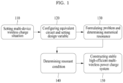
- FIG. 1 illustrates an example of a process of constructing a wireless power transfer system using a magnetic resonant condition determining method according to an example embodiment.
- FIG. 1 illustrates a first process 110 for setting a multi-device wireless charge situation, a second process 120 for configuring an equivalent circuit and setting a design variable, a third process 130 for formulating a problem and determining a numerical resonance, a fourth process 140 for determining a resonant condition, and a fifth process 150 for constructing a stable high-efficient multi-device wireless power charge system.
- Magnetic resonance type wireless power transfer technology including a single transmitter/receiver may determine a resonant condition through a compensation combination of a coil inductance and a capacitance on a closed circuit of the transmitter/receiver and may maximize a power transfer efficiency accordingly.
- the resonant condition in response to occurrence of a change in a distance between the transmitter and the receiver or an angle of the receiver, the resonant condition may be matched by varying an input frequency.
- a magnetic characteristic between the transmitter and the receiver may vary due to a change in tissue cell and a change in blood flow, such as contraction or relaxation of blood vessel, which may lead to degrading the power transfer efficiency.
- the power transfer efficiency may be compensated for by varying the input frequency.
- an inductance value at an individual transmitter/receiver may be adjusted by adjusting a position of the resonator, which may lead to achieving the optimal efficiency.
- the enhancement of power transfer efficiency through control of the operating frequency (f), the inductance (L) of the transmitter/receiver, and the compensation capacitance (C) corresponds to a research result at the magnetic resonance type wireless power transfer system including the single transmitter/receiver and thus, may not be directly applied to resonant condition determination and compensation of a magnetic resonance type wireless power transfer system including a multi-transmitter/receiver.
- an available design variable for the optimal design may be a capacitance (C) of a transmitter/receiver and an input voltage (Vt) of a transmitter.
- FIG. 2 illustrates an example of an equivalent circuit configuration and a design variable setting according to an example embodiment
- FIG. 3 illustrates an example of a problem formulation and a numerical resonance determination according to an example embodiment
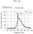
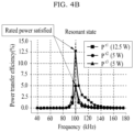
- FIGS. 4A and 4B illustrate examples of determining a resonant condition according to an example embodiment.
- a resonant condition for a single transmitter/receiver may derive a mathematical theory.
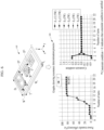
- FIG. 5 illustrates an example of determining a resonant condition for a single transmitter/receiver wireless power transfer system according to an example embodiment.
- FIG. 5 illustrates a single transmitter/receiver wireless power transfer system 510 and graphs 520 showing a resonance determination process for the single transmitter/receiver wireless power transfer system 510.
- Table 1 shows that a mathematical theory about a resonant condition, i.e., a "resonant condition theoretical value” and a "resonance determination result value" acquired using a magnetic resonant condition determining method according to an example embodiment are almost identical to each other.
- FIG. 6 illustrates an example of determining a resonant condition for a multi-transmitter/receiver wireless power transfer system using a magnetic resonant condition determining method according to an example embodiment.
- FIG. 6 illustrates a multi-transmitter/receiver wireless power transfer system 610 and graphs 620 showing a resonance determination process for the multi-transmitter/receiver wireless power transfer system 620.
- a resonance determination result may be represented as the following Table 2.
- the wireless power transfer system having a multi-transmitter/receiver may have different rated power with respect to an individual receiver.
- the example embodiments may satisfy different rated power for each receiver and also maximize the power transfer efficiency by assigning a constraint condition about the rated power of the individual receiver.
- a computer apparatus that performs a magnetic resonant condition determining method may measure, for example, power transfer efficiency and rated power of a target system with varying each of an operating frequency, a compensation capacitance, and an input voltage by a preset magnitude.
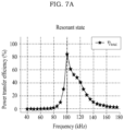
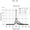
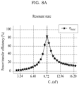
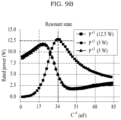
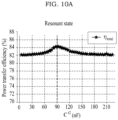
- FIGS. 7A to 12B illustrate examples of verifying that a power transfer efficiency is maximized and rated power is met from graphs showing a change in a parameter of a design variable and a frequency in a resonant condition set using a magnetic resonant condition determining method according to an example embodiment.
- a resonant state may indicate a state in which the rated power is met and the power transfer efficiency is maximized. That is, in the graphs of FIGS. 7A to 12B , vertical dotted lines represent a resonant condition that is derived through the magnetic resonant condition determining method according to the example embodiment.
- FIGS. 7A to 12B show that resonant conditions derived through the magnetic resonant condition determining method satisfy all of the individual rated power and maximize the power transfer efficiency.
- the graphs of FIGS. 7A and 7B show that the power transfer efficiency and the rated power are maximized at a frequency of 100 kHz.
- a relative position between a transmitter and a receiver, a number of transmitters/receivers, rated power of a receiver, and a type may vary.
- FIGS. 13A and 13B illustrate examples of a change in charging performance including power transfer efficiency due to a misalignment of charging devices according to an example embodiment.
- the coupling effect between transmitting and receiving coils and the required rated power of a receiver may vary and a resonant condition may vary accordingly. Without correcting the resonant condition that is changed in response to the change in the environment, the required rated power of the receiver may not be satisfied and the power transfer efficiency may be significantly degraded.
- the resonant condition about the changed environment may be redetermined and resonance compensation may be performed by reflecting the redetermined resonant condition.
- Table 3 shows a mutual inductance change between a transmitter and a receiver and Table 4 shows a change in system performance.
- Table 3 mutual inductance before changing position and angle after changing position and angle M t r 1 (uH) b/w t-r 1 17.44 12.12 M t r 2 (uH) b/w t - r 2 5.66 5.47 M t r 3 (uH) b/w t - r 3 6.72 5.27 M r 1 r 2 (uH) b/w r 1 - r 2 -0.57 -0.72 M r 1 r 3 (uH) b/w r 1 - r 3 -0.08 -0.35 M r 2 r 3 (uH) b/w r 2 - r 3 -0.32 -0.02 [Table 4] system performance before changing position and angle after changing position and angle change rate (%) transmitter rated power P t (W) 27.57 36.43 32.14
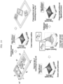
- FIG. 14 illustrates an example of redetermining a resonant condition in response to a change in a position and an angle of a multi-transmitter/receiver and performing a resonance compensation according to an example embodiment.
- the computer apparatus in response to detecting a degradation in performance by a change in a resonant condition, the computer apparatus according to the example embodiment may redetermine the resonant condition for each state through the magnetic resonant condition determining method according to the example embodiment and may provide the redetermined resonant condition, thereby restoring the performance of the multi-transmitter receiver wireless power transfer system.
- the example embodiments may overcome the degradation in the system performance occurring due to, for example, a change in a relative position between a transmitter and a receiver and accordingly, may increase a degree of freedom of a charge state for the multi-transmitter/receiver, for example, a position and an angle of each of transmitters/receivers.
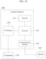
- FIG. 15 is a diagram illustrating an example of a configuration of a computer apparatus according to an example embodiment.
- a computer apparatus 1500 may include a memory 1510, a processor 1520, a communication interface 1530, and an input/output (I/O) interface 1540.
- the memory 1510 may include a permanent mass storage device, such as random access memory (RAM), read only memory (ROM), and disk drive.
- the permanent mass storage device such as ROM and disk drive, may be included in the computer apparatus 1500 as a permanent storage device separate from the memory 1510.
- an OS and at least one program code may be stored in the memory 1510.
- Such software components may be loaded to the memory 1510 from another non-transitory computer-readable storage medium separate from the memory 1510.
- the other non-transitory computer-readable storage medium may include a non-transitory computer-readable recording medium, for example, a floppy drive, a disk, a tape, a DVD/CD-ROM drive, a memory card, etc.
- software components may be loaded to the memory 1510 through the communication interface 1530, instead of, or in addition to, the non-transitory computer-readable storage medium.
- software components may be loaded to the memory 1510 of the computer apparatus 1500 based on a computer program installed by files received over a network 1560.
- the processor 1520 may be configured to process computer-readable instructions of a computer program by performing basic arithmetic operations, logic operations, and I/O operations.
- the computer-readable instructions may be provided from the memory 1510 or the communication interface 1530 to the processor 1520.
- the processor 1520 may be configured to execute received instructions in response to a program code stored in a storage device, such as the memory 1510.
- the communication interface 1530 may provide a function for communication between the computer apparatus 1500 and another apparatus, for example, the aforementioned storage device, over the network 1560.
- the processor 1520 of the computer apparatus 1500 may transfer a request or an instruction, data, a file, etc., created based on the program code stored in the storage device such as the memory 1510, to other devices over the network 1560 under control of the communication interface 1530.
- a signal, an instruction, data, a file, etc., from another apparatus may be received at the computer apparatus 1500 by going through the communication interface 1530 of the computer apparatus 1500 and the network 1560.
- a signal, an instruction, data, etc., received through the communication interface 1530 may be transferred to the processor 1520 or the memory 1510, and content, a file, etc., may be stored in a storage medium, for example, the aforementioned permanent storage device, further includable in the computer apparatus 1500.
- the I/O interface 1540 may be a device used for interface with an I/O apparatus 1550.
- an input device may include a device, such as a microphone, a keyboard, and a mouse
- an output device may include a device, such as a display and a speaker.
- the I/O interface 1540 may be a device for interface with an apparatus in which an input function and an output function are integrated into a single function, such as a touchscreen.
- the I/O apparatus 1550 may be configured as a single apparatus with the computer apparatus 1500.
- the computer apparatus 1500 may include a greater or less number of components than a number of components shown in FIG. 15 .
- the computer apparatus 1500 may include at least a portion of the I/O apparatus 1550, or may further include other components, for example, a transceiver, a database (DB), and the like.
- DB database
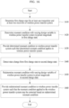
- FIG. 16 is a flowchart illustrating an example of a magnetic resonant condition determining method according to an example embodiment.
- the magnetic resonant condition determining method of FIG. 16 may be performed by the aforementioned computer apparatus 1500.
- the processor 1520 of the computer apparatus 1500 may be configured to execute a control instruction according to a code of at least one program or a code of an OS included in the memory 1510.
- the processor 1520 may control the computer apparatus 1500 to perform operations 1610 to 1660 included in the method of FIG. 16 in response to the control instruction provided from the code stored in the computer apparatus 1500.
- the computer apparatus 1500 determines an initial charge state, for example, a first charge state for at least one transmitter and at least two receivers of a wireless power transfer system.
- a charge state for a transmitter and a receiver may be determined based on at least one of a number of transmitters of the wireless power transfer system, a number of receivers that are supplied with wireless power through the wireless power transfer system, a charge capacity of a receiver, a relative position between a transmitter and a receiver, and an orientation angle of a receiver being charged.
- the computer apparatus 1500 determines a resonant condition with varying a design variable in the wireless power transfer system by a preset magnitude in the initial charge state, for example, the first charge state
- the design variable includes at least one parameter among an operating frequency, a compensation capacitance, and an input voltage.
- the computer apparatus 1500 may acquire a value of a parameter when a resonant condition is met, with varying parameters, such as, for example, the operating frequency, the compensation capacitance, and the input voltage, by a preset magnitude.
- the resonant condition includes a value of a least one parameter that satisfies the charge capacity of each of the at least two receivers and also maximizes the power transfer efficiency.
- the resonant condition may include at least one of a value of the operating frequency, a value of the compensation capacitance, and a value of the input voltage that simultaneously satisfy the charge capacity and maximize the power transfer efficiency.
- the computer apparatus 1500 may provide the determined resonant condition to the wireless power transfer system such that the determined resonant condition applies to the wireless power transfer system.
- the wireless power transfer system may satisfy the resonant condition by setting at least one of the operating frequency, the compensation capacitance, and the input voltage based on the provided condition, for example, at least one of the value of the operating frequency, the value of the compensation capacitance, and the value of the input voltage.
- the computer apparatus 1500 detects a state change from the initial charge state, for example, the first charge state, to another charge state, for example, a second charge state.
- the computer apparatus 1500 detects the state change by detecting a change in at least one of a number of transmitters of the wireless power transfer system, a number of receivers that are supplied with wireless power through the wireless power transfer system, a charge capacity of a receiver, a relative position between a transmitter and a receiver, and an orientation angle of a receiver being charged.
- the change is detected based on an output value of a sensor included in the wireless power transfer system.
- the wireless power transfer system includes sensors for sensing the number of transmitters of the wireless power transfer system, the number of receivers that are supplied with the wireless power through the wireless power transfer system, a charge capacity of a receiver, a relative position between a transmitter and a receiver, and an orientation angle of a receiver being charged.
- the computer apparatus 1500 detects the at least one change from output values of the sensors included in the wireless power transfer system.
- any type of sensors capable of sensing a number of receivers provided at a charging position, a relative position thereof, and an orientation angle thereof, or capable of sensing a change in the number of receivers, the relative position, and the orientation angle such as a proximity sensor, a pressure sensor, and/or a motion sensor, are used for the sensors disclosed herein.
- the computer apparatus 1500 redetermines the resonant condition with varying the design variable of the wireless power transfer system by the preset magnitude in the other charge state, for example, the second charge state.
- a change in the charge state may cause a change in the resonant condition due to a change in a coupling effect between a transmitter and a receiver and a change in required rated power of a receiver.
- the computer apparatus 1500 may redetermine the resonant condition in response to the change in the charge state.
- the design variable may include at least one parameter among the operating frequency, the compensation capacitance, and the input voltage.
- the computer apparatus 1500 may provide the redetermined resonant condition to the wireless power transfer system such that the resonant condition applied to the wireless power transfer system may be corrected based on the redetermined resonant condition.
- the wireless power transfer system may correct the applied resonant condition based on the redetermined resonant condition and may restore the performance degraded by the state change.
- correcting a resonant condition by redetermining the resonant condition in response to a state change from an initial charge state to another charge state is described with reference to FIG. 16
- correcting the resonant condition may be performed every time the charge state varies.
- the computer apparatus 1500 may be configured to be included in the wireless power transfer system or may be configured as an apparatus separate from the wireless power transfer system and to communicate with the wireless power transfer system over a network.
- the computer apparatus 1500 may be configured to be included in the wireless power transfer system and directly vary at least one parameter by a preset magnitude, and, depending on example embodiments, may be configured to control the wireless power transfer system to vary at least one parameter by the preset magnitude through communication with the wireless power transfer system.
- wireless power transfer technology applies to a charging system of an electrical vehicle, the electrical vehicle may be charged simply with parking in a designated place. Accordingly, the convenience and stability of a driver may be significantly enhanced.
- charging infrastructure for example, an inverter and a converter, may be efficiently used at the time of simultaneously charging a plurality of electrical vehicles. In particular, if a charging environment changes due to a change in the number of vehicles being charged or a misalignment, it is possible to redetermine a resonant condition and to perform a correction by applying the change to the charging environment.
- a drone is used in various fields, for example, delivery, shooting, and extinguishing a fire.
- an operation time of the drone is limited due to, for example, a battery capacity.
- a charging place is required in a transit region. If an autonomous driving and wireless charging is linked, the drone may be further effectively operated.
- the drone may not stably land at a charging point depending on a weather condition. According to the example embodiments, it is possible to effectively cope with an issue caused by inconsistency at a landing.
- the example embodiments may be used for various unmanned and wireless electronic products, for example, an unmanned cleaner, an unmanned logistics robot, a mobile phone, a tablet PC, a wireless keyboard, and a mouse.
- an unmanned cleaner for example, an unmanned cleaner, an unmanned logistics robot, a mobile phone, a tablet PC, a wireless keyboard, and a mouse.
- the example embodiments may be readily expandable to a multi-transmitter/receiver magnetic resonance type system about the existing studies.
- power may be supplied to a plurality of receivers using a single transmitter or a small number of transmitters. Accordingly, it is possible to save cost used for constructing infrastructure and to enhance a transmission distance through magnetic resonance.
- power supply may be performed effectively and stably, which may lead to expanding the technical ability and marketability of unmanned products, such as, for example, an unmanned cleaner and a logistics robot.
- a resonant condition based on a charge state, for example, a number of charging devices and a relative position between charging devices, for a multi-transmitter/receiver of a wireless power transfer system. Also, it is possible to support a wireless power transfer system to stably and efficiently transfer wireless power by determining a new resonant condition in response to a change in a resonant condition, such as a change of a charge state, for example, a number of charging devices and a relative position between charging devices, for a multi-transmitter/receiver of the wireless power transfer system, and by performing a resonance compensation through application of the determined new resonant condition.
- the apparatuses described herein may be implemented using hardware components, software components, and/or a combination thereof.
- the apparatuses and the components described herein may be implemented using one or more general-purpose or special purpose computers, such as, for example, a processor, a controller, an arithmetic logic unit (ALU), a digital signal processor, a microcomputer, a field programmable gate array (FPGA), a programmable logic unit (PLU), a microprocessor, or any other device capable of responding to and executing instructions in a defined manner.
- the processing device may run an operating system (OS) and one or more software applications that run on the OS.
- the processing device also may access, store, manipulate, process, and create data in response to execution of the software.
- OS operating system
- the processing device also may access, store, manipulate, process, and create data in response to execution of the software.
- a processing device may include multiple processing elements and/or multiple types of processing elements.
- a processing device may include multiple processors or a processor and a controller.
- different processing configurations are possible, such as parallel processors.
- the software may include a computer program, a piece of code, an instruction, or some combination thereof, for independently or collectively instructing or configuring the processing device to operate as desired.
- Software and/or data may be embodied permanently or temporarily in any type of machine, component, physical or virtual equipment, computer storage medium or device, or in a propagated signal wave capable of providing instructions or data to or being interpreted by the processing device.
- the software also may be distributed over network coupled computer systems so that the software is stored and executed in a distributed fashion.
- the software and data may be stored by one or more computer readable recording mediums.
- the methods according to the above-described example embodiments may be recorded in non-transitory computer-readable media including program instructions to implement various operations of the above-described example embodiments.
- the media may also include, alone or in combination with the program instructions, data files, data structures, and the like.
- the program instructions recorded on the media may be those specially designed and constructed for the purposes of example embodiments, or they may be of the kind well-known and available to those having skill in the computer software arts.
- non-transitory computer-readable media examples include magnetic media such as hard disks, floppy disks, and magnetic tapes; optical media such as CD-ROM discs, and DVDs; magneto-optical media such as floptical disks; and hardware devices that are specially configured to store and perform program instructions, such as read-only memory (ROM), random access memory (RAM), flash memory, and the like.
- program instructions include both machine code, such as produced by a compiler, and files containing higher level code that may be executed by the computer using an interpreter.
- the above-described devices may be configured to act as one or more software modules in order to perform the operations of the above-described example embodiments, or vice versa.
Landscapes
- Engineering & Computer Science (AREA)
- Computer Networks & Wireless Communication (AREA)
- Power Engineering (AREA)
- Signal Processing (AREA)
- Charge And Discharge Circuits For Batteries Or The Like (AREA)
Description
- The following description of example embodiments relates to a method of determining a magnetic resonant condition for a multi-device wireless power transfer system.
- Wireless power transfer refers to a noncontact power transfer technique in which electric energy supplied to a primary coil, for example, a transmitter, induces magnetic field energy and the induced magnetic field energy induces the electric energy again in a secondary coil, for example, a receiver. Research on the wireless power transfer has been actively conducted since the publication of the paper by MIT professor Soljacic in 2006. The wireless power transfer has been applied to a wide range of products ranging from low-power portable electronic devices to high-power train systems. Currently, the scale of related market is growing rapidly and is predicted to reach about 14 billion dollars by 2024.
- Nonradiative wireless power transfer is classified into a magnetic induction type and a magnetic resonance type.
- In the case of the magnetic induction type wireless power transfer, power may be effectively supplied to a secondary coil from the primary coil through a strong coupling effect between a primary coil, for example, a transmitter, and the secondary coil, for example, a receiver. For example, a wireless charging apparatus of magnetic induction type is disclosed in
Korean Patent Laid-Open Publication No. 10-2013-0071764 - In the case of the magnetic resonance type wireless power transfer, a power transfer efficiency may be enhanced by maximizing a coupling effect through a magnetic resonance effect although a coupling state between transmitting and receiving coils is loose, for example, although an airgap therebetween is large.
- Currently, commercialization of the magnetic induction type is ongoing based on small electronic products, for example, mobile phones, earphones, and tablet personal computers (PCs), and the magnetic resonance type applies to products, for example, vehicles, large home appliances, and motors, which require a large airgap and great power.
- With its high convenience and stability compared to wired power transfer technology, wireless power transfer technology is widely adopted to products ranging from small home appliances using small power to products using large power, such as electric vehicles. A large number of products have been already released. However, there is a great need to develop wireless power transfer technology or product capable of simultaneously charging a plurality of devices having different rated power and having a high degree of freedom for a transmission distance. According to the trend of wireless power transfer standardization of International Telecommunication Union Telecommunication Standardization Sector (ITU-T), a service for simultaneously charging a plurality of terminals is selected as a representative example of applying the wireless power transfer. In the case of the magnetic induction type, there are many examples of commercialization, however, there is a limit to increase a transmission distance. In the case of the magnetic resonance type, a relatively high power transfer efficiency may be secured even in a relatively long transmission distance through a resonance phenomenon, however, the power transfer efficiency varies greatly depending on whether a resonant condition is met.
- In particular, a resonant condition for a single transmitter/receiver may derive a mathematical theory, however, a resonant condition for a multi-transmitter/receiver may not derive a mathematical theory due to a mutual coupling effect between a plurality of coils and different rated power required by an individual receiver. Also, in response to a change in a configuration of a multi-transmitter/receiver system, for example, a number of transmitters/receivers, a charge capacity of a receiver, a relative position between a transmitter and a receiver, and a magnetic characteristic between a transmitter and a receiver, the mutual coupling effect may vary, which leads to changing the resonant condition. In the case of the magnetic resonance type, unless the resonant condition is met, the power transfer efficiency drops sharply. Accordingly, if the system change occurs, resonance compensation needs to be performed by reflecting the system change.
- Documents
US 2014/111156 A1 andUS 2014/266027 A1 relate to multi-device wireless power transmission systems and disclose methods for operating such systems. - The invention proposes a method according to
claim 1 and a computer apparatus according toclaim 5. - Further advantageous embodiments of the invention are disclosed in the dependent claims.
- Further areas of applicability will become apparent from the description provided herein. The description and specific examples in this summary are intended for purposes of illustration only and are not intended to limit the scope of the present disclosure.
- These and/or other aspects, features, and advantages of the invention will become apparent and more readily appreciated from the following description of embodiments, taken in conjunction with the accompanying drawings of which:
-
FIG. 1 illustrates an example of a process of constructing a wireless power transfer system using a magnetic resonant condition determining method according to an example embodiment; -
FIG. 2 illustrates an example of an equivalent circuit configuration and a design variable setting according to an example embodiment; -
FIG. 3 illustrates an example of a problem formulation and a numerical resonance determination according to an example embodiment; -
FIGS. 4A and4B illustrate examples of determining a resonant condition according to an example embodiment; -
FIG. 5 illustrates an example of determining a resonant condition for a single transmitter/receiver wireless power transfer system according to an example embodiment; -
FIG. 6 illustrates an example of determining a resonant condition for a multi-transmitter/receiver wireless power transfer system using a magnetic resonant condition determining method according to an example embodiment; -
FIGS. 7A to 12B illustrate examples of verifying that a power transfer efficiency is maximized and rated power is met from graphs showing a change in a parameter of a design variable and a frequency in a resonant condition set using a magnetic resonant condition determining method according to an example embodiment; -
FIGS. 13A and13B illustrate examples of a change in charging performance including a power transfer efficiency due to a misalignment of charging devices according to an example embodiment; -
FIG. 14 illustrates an example of redetermining a resonant condition in response to a change in a position and an angle of a multi-transmitter/receiver and performing a resonance compensation according to an example embodiment; -
FIG. 15 is a diagram illustrating an example of a configuration of a computer apparatus according to an example embodiment; and -
FIG. 16 is a flowchart illustrating an example of a magnetic resonant condition determining method according to an example embodiment. - One or more example embodiments will be described with reference to the accompanying drawings. Advantages and features of the example embodiments, and methods for achieving the same may become explicit by referring to the accompanying drawings and the following example embodiments. Example embodiments, however, may be embodied in various different forms, and should not be construed as being limited to only the illustrated embodiments.
- Unless otherwise noted, like reference characters denote like elements throughout the attached drawings and written description, and thus descriptions will not be repeated.
- When an element or a layer is referred to as being "on," "connected to," "coupled to," or "adjacent to," another element or layer, the element or the layer may be directly on, connected to, coupled to, or adjacent to, the other element or layer, or one or more other intervening elements or layers may be present. In contrast, when an element or a layer is referred to as being "directly on," "directly connected to," "directly coupled to," or "immediately adjacent to," another element or layer, there are no intervening elements or layers present.
- Although the terms "first," "second," "third," etc., may be used herein to describe various elements, components, regions, layers, and/or sections, these elements, components, regions, layers, and/or sections, should not be limited by these terms. These terms are only used to distinguish one element, component, region, layer, or section, from another region, layer, or section. Thus, a first element, component, region, layer, or section, discussed below may be termed a second element, component, region, layer, or section, without departing from the scope of this disclosure.
- Hereinafter, example embodiments will be described with reference to the accompanying drawings.
- The example embodiments relate to a magnetic resonant condition determining method that may determine a resonant condition of a multi-transmitter/receiver wireless power transfer system and may use the determined resonant condition for a resonant condition setting, a computer apparatus performing the magnetic resonant condition determining method, a computer program stored in a non-transitory computer-readable recording medium to perform the magnetic resonant condition determining method on the computer apparatus in conjunction with the computer apparatus, and the non-transitory computer-readable recording medium.
- For example, the magnetic resonant condition determining method according to the example embodiments may be performed by at least one computer apparatus, which is described below. Here, a computer program according an example embodiment may be installed and executed on the computer apparatus and the computer apparatus may perform the magnetic resonant condition determining method according to the example embodiments under control of the executed computer program. The computer program may be stored in a non-transitory computer-readable medium to perform the magnetic resonant condition determining method on the computer apparatus in conjunction with the computer apparatus.
- Here, the computer apparatus performing the magnetic resonant condition determining method may be included in the multi-transmitter/receiver wireless power transfer system or may be connected to the multi-transmitter/receiver wireless power transfer system over a network as an apparatus separate from the multi-transmitter/receiver wireless power transfer system.
- Here, the resonant condition of the multi-transmitter/receiver wireless power transfer may refer to a state in which a charge capacity of an individual charging device is satisfied and a power transfer efficiency is maximized. Also, the expression "multi-transmitter/receiver" describes that any one of a number of transmitters and a number of receivers is two or more.
-
FIG. 1 illustrates an example of a process of constructing a wireless power transfer system using a magnetic resonant condition determining method according to an example embodiment.FIG. 1 illustrates afirst process 110 for setting a multi-device wireless charge situation, asecond process 120 for configuring an equivalent circuit and setting a design variable, athird process 130 for formulating a problem and determining a numerical resonance, afourth process 140 for determining a resonant condition, and afifth process 150 for constructing a stable high-efficient multi-device wireless power charge system. - Magnetic resonance type wireless power transfer technology including a single transmitter/receiver may determine a resonant condition through a compensation combination of a coil inductance and a capacitance on a closed circuit of the transmitter/receiver and may maximize a power transfer efficiency accordingly.
- For example, a resonant condition for a single transmitter/receiver may be induced as represented by the following
Equation 1 through a combination of an operating frequency (f) on a closed circuit of the transmitter/receiver, an inductance (L) of the transmitter/receiver, and a compensation capacitance (C).
- With respect to the operating frequency (f), in response to occurrence of a change in a distance between the transmitter and the receiver or an angle of the receiver, the resonant condition may be matched by varying an input frequency. In the case of a medical device that operates inside a human body, a magnetic characteristic between the transmitter and the receiver may vary due to a change in tissue cell and a change in blood flow, such as contraction or relaxation of blood vessel, which may lead to degrading the power transfer efficiency. Here, the power transfer efficiency may be compensated for by varying the input frequency.
- With respect to the inductance (L) of the transmitter/receiver, in the case of a system having a resonator between the transmitter and the receiver, an inductance value at an individual transmitter/receiver may be adjusted by adjusting a position of the resonator, which may lead to achieving the optimal efficiency.
- With respect to the compensation capacitance (C), if it is difficult to vary the operating frequency (f) or the inductance (L) due to a fixed frequency by various types of rules or a complexity of an inductance change system, it is possible to enhance the power transfer efficiency by changing the capacitance using a variable capacitor.
- Here, the enhancement of power transfer efficiency through control of the operating frequency (f), the inductance (L) of the transmitter/receiver, and the compensation capacitance (C) corresponds to a research result at the magnetic resonance type wireless power transfer system including the single transmitter/receiver and thus, may not be directly applied to resonant condition determination and compensation of a magnetic resonance type wireless power transfer system including a multi-transmitter/receiver.
- In the case of magnetic resonance type wires power transfer technology including a multi-transmitter/receiver, required rated current needs to flow in a circuit of an individual receiver for stable charging and a current phase difference of an individual transmitter/receiver needs to be considered due to a coupling effect between multi-transmitter and receiver. Accordingly, if maximization of the power transfer efficiency and the rated power of an individual receiver are all considered with respect to resonance determination of a multi-transmitter/receiver, a difficulty and a complexity in the resonance determination may significantly increase according to an increase in the number of receivers. According to example embodiments, it is possible to effectively determine a resonant condition for a multi-transmitter/receiver through a numerical method, such as an optimal design theory, instead of using a mathematical approach method. For example, when rated power of an individual receiver and a coil design of a transmitter/receiver and a relative position between a transmitter and a receiver are determined, an available design variable for the optimal design may be a capacitance (C) of a transmitter/receiver and an input voltage (Vt) of a transmitter.
-
FIG. 2 illustrates an example of an equivalent circuit configuration and a design variable setting according to an example embodiment,FIG. 3 illustrates an example of a problem formulation and a numerical resonance determination according to an example embodiment, andFIGS. 4A and4B illustrate examples of determining a resonant condition according to an example embodiment. - As described above, a resonant condition for a single transmitter/receiver may derive a mathematical theory.
-
FIG. 5 illustrates an example of determining a resonant condition for a single transmitter/receiver wireless power transfer system according to an example embodiment.FIG. 5 illustrates a single transmitter/receiver wirelesspower transfer system 510 andgraphs 520 showing a resonance determination process for the single transmitter/receiver wirelesspower transfer system 510. Here, the following Table 1 shows that a mathematical theory about a resonant condition, i.e., a "resonant condition theoretical value" and a "resonance determination result value" acquired using a magnetic resonant condition determining method according to an example embodiment are almost identical to each other.[Table 1] resonant condition theoretical value resonance determination result value error rate (%) design variable transmitter capacitance Ct (nF) 10.2 10.19 0.10 receiver capacitance C r1 (nF) 45.27 45.82 1.21 input voltage Vt (nF) 16.77 16.91 0.83 system performance receiver rated power P r1 (W) 12.50 12.59 0.72 transmitter capacitance ηtotal (%) 90.10 89.57 0.59 -
FIG. 6 illustrates an example of determining a resonant condition for a multi-transmitter/receiver wireless power transfer system using a magnetic resonant condition determining method according to an example embodiment.FIG. 6 illustrates a multi-transmitter/receiver wirelesspower transfer system 610 andgraphs 620 showing a resonance determination process for the multi-transmitter/receiver wirelesspower transfer system 620. Here, a resonance determination result may be represented as the following Table 2.[Table 2] design variable transmitter capacitance Ct r 1 receiver capacitance C r1 r 2 receiver capacitance C r2 r 3 receiver capacitance C r3 input voltage Vt resonance determination result value 9.71 nF 33.93 nF 90.85 nF 74.68 nF 16.68 V system performance transmitter rated power Pt r 1 receiver rated power P r1 r 2 receiver rated power P r2 r 3 receiver rated power P r3 power transfer efficiency ηtotal 27.57 W 12.81 W 4.93 W 5.12 W 84.36% - The wireless power transfer system having a multi-transmitter/receiver may have different rated power with respect to an individual receiver. The example embodiments may satisfy different rated power for each receiver and also maximize the power transfer efficiency by assigning a constraint condition about the rated power of the individual receiver. For example, to verify an application result about a multi-transmitter/receiver, a computer apparatus that performs a magnetic resonant condition determining method according to an example embodiment may measure, for example, power transfer efficiency and rated power of a target system with varying each of an operating frequency, a compensation capacitance, and an input voltage by a preset magnitude.
-
FIGS. 7A to 12B illustrate examples of verifying that a power transfer efficiency is maximized and rated power is met from graphs showing a change in a parameter of a design variable and a frequency in a resonant condition set using a magnetic resonant condition determining method according to an example embodiment. In the graphs, a resonant state may indicate a state in which the rated power is met and the power transfer efficiency is maximized. That is, in the graphs ofFIGS. 7A to 12B , vertical dotted lines represent a resonant condition that is derived through the magnetic resonant condition determining method according to the example embodiment. Here, the graphs ofFIGS. 7A to 12B show that resonant conditions derived through the magnetic resonant condition determining method satisfy all of the individual rated power and maximize the power transfer efficiency. For example, the graphs ofFIGS. 7A and7B show that the power transfer efficiency and the rated power are maximized at a frequency of 100 kHz. - During an operation of the multi-transmitter/receiver wireless power transfer system, a relative position between a transmitter and a receiver, a number of transmitters/receivers, rated power of a receiver, and a type may vary.
-
FIGS. 13A and13B illustrate examples of a change in charging performance including power transfer efficiency due to a misalignment of charging devices according to an example embodiment. In response to such a change in a charging environment, the coupling effect between transmitting and receiving coils and the required rated power of a receiver may vary and a resonant condition may vary accordingly. Without correcting the resonant condition that is changed in response to the change in the environment, the required rated power of the receiver may not be satisfied and the power transfer efficiency may be significantly degraded. According to example embodiments, the resonant condition about the changed environment may be redetermined and resonance compensation may be performed by reflecting the redetermined resonant condition. The following Table 3 shows a mutual inductance change between a transmitter and a receiver and Table 4 shows a change in system performance.[Table 3] mutual inductance before changing position and angle after changing position and angle 
17.44 12.12 
5.66 5.47 
6.72 5.27 
-0.57 -0.72 
-0.08 -0.35 
-0.32 -0.02 [Table 4] system performance before changing position and angle after changing position and angle change rate (%) transmitter rated power Pt (W) 27.57 36.43 32.14 r 1 receiver rated power P r1 (W) 12.81 8.67 32.32 r 2 receiver rated power P r2 (W) 4.93 5.49 11.36 r 3 receiver rated power 5.12 10.91 113.09 P r3 (W) power transfer efficiency ηtotal (%) 84.36 68.82 18.42 -
FIG. 14 illustrates an example of redetermining a resonant condition in response to a change in a position and an angle of a multi-transmitter/receiver and performing a resonance compensation according to an example embodiment. For example, in response to detecting a degradation in performance by a change in a resonant condition, the computer apparatus according to the example embodiment may redetermine the resonant condition for each state through the magnetic resonant condition determining method according to the example embodiment and may provide the redetermined resonant condition, thereby restoring the performance of the multi-transmitter receiver wireless power transfer system. - That is, the example embodiments may overcome the degradation in the system performance occurring due to, for example, a change in a relative position between a transmitter and a receiver and accordingly, may increase a degree of freedom of a charge state for the multi-transmitter/receiver, for example, a position and an angle of each of transmitters/receivers.
-
FIG. 15 is a diagram illustrating an example of a configuration of a computer apparatus according to an example embodiment. Referring toFIG. 15 , acomputer apparatus 1500 may include amemory 1510, aprocessor 1520, acommunication interface 1530, and an input/output (I/O)interface 1540. Thememory 1510 may include a permanent mass storage device, such as random access memory (RAM), read only memory (ROM), and disk drive. Here, the permanent mass storage device, such as ROM and disk drive, may be included in thecomputer apparatus 1500 as a permanent storage device separate from thememory 1510. Also, an OS and at least one program code may be stored in thememory 1510. Such software components may be loaded to thememory 1510 from another non-transitory computer-readable storage medium separate from thememory 1510. The other non-transitory computer-readable storage medium may include a non-transitory computer-readable recording medium, for example, a floppy drive, a disk, a tape, a DVD/CD-ROM drive, a memory card, etc. According to other example embodiments, software components may be loaded to thememory 1510 through thecommunication interface 1530, instead of, or in addition to, the non-transitory computer-readable storage medium. For example, software components may be loaded to thememory 1510 of thecomputer apparatus 1500 based on a computer program installed by files received over anetwork 1560. - The
processor 1520 may be configured to process computer-readable instructions of a computer program by performing basic arithmetic operations, logic operations, and I/O operations. The computer-readable instructions may be provided from thememory 1510 or thecommunication interface 1530 to theprocessor 1520. For example, theprocessor 1520 may be configured to execute received instructions in response to a program code stored in a storage device, such as thememory 1510. - The
communication interface 1530 may provide a function for communication between thecomputer apparatus 1500 and another apparatus, for example, the aforementioned storage device, over thenetwork 1560. For example, theprocessor 1520 of thecomputer apparatus 1500 may transfer a request or an instruction, data, a file, etc., created based on the program code stored in the storage device such as thememory 1510, to other devices over thenetwork 1560 under control of thecommunication interface 1530. Inversely, a signal, an instruction, data, a file, etc., from another apparatus may be received at thecomputer apparatus 1500 by going through thecommunication interface 1530 of thecomputer apparatus 1500 and thenetwork 1560. For example, a signal, an instruction, data, etc., received through thecommunication interface 1530 may be transferred to theprocessor 1520 or thememory 1510, and content, a file, etc., may be stored in a storage medium, for example, the aforementioned permanent storage device, further includable in thecomputer apparatus 1500. - The I/
O interface 1540 may be a device used for interface with an I/O apparatus 1550. For example, an input device may include a device, such as a microphone, a keyboard, and a mouse, and an output device may include a device, such as a display and a speaker. As another example, the I/O interface 1540 may be a device for interface with an apparatus in which an input function and an output function are integrated into a single function, such as a touchscreen. The I/O apparatus 1550 may be configured as a single apparatus with thecomputer apparatus 1500. - According to other example embodiments, the
computer apparatus 1500 may include a greater or less number of components than a number of components shown inFIG. 15 . However, there is no need to clearly illustrate many components according to the related art. For example, thecomputer apparatus 1500 may include at least a portion of the I/O apparatus 1550, or may further include other components, for example, a transceiver, a database (DB), and the like. -
FIG. 16 is a flowchart illustrating an example of a magnetic resonant condition determining method according to an example embodiment. The magnetic resonant condition determining method ofFIG. 16 may be performed by theaforementioned computer apparatus 1500. For example, theprocessor 1520 of thecomputer apparatus 1500 may be configured to execute a control instruction according to a code of at least one program or a code of an OS included in thememory 1510. Here, theprocessor 1520 may control thecomputer apparatus 1500 to performoperations 1610 to 1660 included in the method ofFIG. 16 in response to the control instruction provided from the code stored in thecomputer apparatus 1500. - Referring to
FIG. 16 , inoperation 1610, thecomputer apparatus 1500 determines an initial charge state, for example, a first charge state for at least one transmitter and at least two receivers of a wireless power transfer system. Here, a charge state for a transmitter and a receiver may be determined based on at least one of a number of transmitters of the wireless power transfer system, a number of receivers that are supplied with wireless power through the wireless power transfer system, a charge capacity of a receiver, a relative position between a transmitter and a receiver, and an orientation angle of a receiver being charged. - In
operation 1620, thecomputer apparatus 1500 determines a resonant condition with varying a design variable in the wireless power transfer system by a preset magnitude in the initial charge state, for example, the first charge state The design variable includes at least one parameter among an operating frequency, a compensation capacitance, and an input voltage. For example, as shown in the graphs ofFIGS. 7A to 12B , thecomputer apparatus 1500 may acquire a value of a parameter when a resonant condition is met, with varying parameters, such as, for example, the operating frequency, the compensation capacitance, and the input voltage, by a preset magnitude. Here, the resonant condition includes a value of a least one parameter that satisfies the charge capacity of each of the at least two receivers and also maximizes the power transfer efficiency. For example, the resonant condition may include at least one of a value of the operating frequency, a value of the compensation capacitance, and a value of the input voltage that simultaneously satisfy the charge capacity and maximize the power transfer efficiency. - In
operation 1630, thecomputer apparatus 1500 may provide the determined resonant condition to the wireless power transfer system such that the determined resonant condition applies to the wireless power transfer system. The wireless power transfer system may satisfy the resonant condition by setting at least one of the operating frequency, the compensation capacitance, and the input voltage based on the provided condition, for example, at least one of the value of the operating frequency, the value of the compensation capacitance, and the value of the input voltage. - In
operation 1640, thecomputer apparatus 1500 detects a state change from the initial charge state, for example, the first charge state, to another charge state, for example, a second charge state. Thecomputer apparatus 1500 detects the state change by detecting a change in at least one of a number of transmitters of the wireless power transfer system, a number of receivers that are supplied with wireless power through the wireless power transfer system, a charge capacity of a receiver, a relative position between a transmitter and a receiver, and an orientation angle of a receiver being charged. Here, the change is detected based on an output value of a sensor included in the wireless power transfer system. In detail, the wireless power transfer system includes sensors for sensing the number of transmitters of the wireless power transfer system, the number of receivers that are supplied with the wireless power through the wireless power transfer system, a charge capacity of a receiver, a relative position between a transmitter and a receiver, and an orientation angle of a receiver being charged. Thecomputer apparatus 1500 detects the at least one change from output values of the sensors included in the wireless power transfer system. For example, any type of sensors capable of sensing a number of receivers provided at a charging position, a relative position thereof, and an orientation angle thereof, or capable of sensing a change in the number of receivers, the relative position, and the orientation angle, such as a proximity sensor, a pressure sensor, and/or a motion sensor, are used for the sensors disclosed herein. - In
operation 1650, thecomputer apparatus 1500 redetermines the resonant condition with varying the design variable of the wireless power transfer system by the preset magnitude in the other charge state, for example, the second charge state. As described above, a change in the charge state may cause a change in the resonant condition due to a change in a coupling effect between a transmitter and a receiver and a change in required rated power of a receiver. Accordingly, thecomputer apparatus 1500 may redetermine the resonant condition in response to the change in the charge state. The design variable may include at least one parameter among the operating frequency, the compensation capacitance, and the input voltage. - In
operation 1660, thecomputer apparatus 1500 may provide the redetermined resonant condition to the wireless power transfer system such that the resonant condition applied to the wireless power transfer system may be corrected based on the redetermined resonant condition. The wireless power transfer system may correct the applied resonant condition based on the redetermined resonant condition and may restore the performance degraded by the state change. - Although an example of correcting a resonant condition by redetermining the resonant condition in response to a state change from an initial charge state to another charge state is described with reference to
FIG. 16 , correcting the resonant condition may be performed every time the charge state varies. - Meanwhile, as described above, the
computer apparatus 1500 may be configured to be included in the wireless power transfer system or may be configured as an apparatus separate from the wireless power transfer system and to communicate with the wireless power transfer system over a network. For example, thecomputer apparatus 1500 may be configured to be included in the wireless power transfer system and directly vary at least one parameter by a preset magnitude, and, depending on example embodiments, may be configured to control the wireless power transfer system to vary at least one parameter by the preset magnitude through communication with the wireless power transfer system. - Due to environmental issues, interest and demand for electrical vehicles are currently on the exponential increase. If wireless power transfer technology applies to a charging system of an electrical vehicle, the electrical vehicle may be charged simply with parking in a designated place. Accordingly, the convenience and stability of a driver may be significantly enhanced. If example embodiments apply to the charging system of the electrical vehicle, charging infrastructure, for example, an inverter and a converter, may be efficiently used at the time of simultaneously charging a plurality of electrical vehicles. In particular, if a charging environment changes due to a change in the number of vehicles being charged or a misalignment, it is possible to redetermine a resonant condition and to perform a correction by applying the change to the charging environment.
- Currently, a drone is used in various fields, for example, delivery, shooting, and extinguishing a fire. However, an operation time of the drone is limited due to, for example, a battery capacity. To use the drone in a stable manner, a charging place is required in a transit region. If an autonomous driving and wireless charging is linked, the drone may be further effectively operated. Here, the drone may not stably land at a charging point depending on a weather condition. According to the example embodiments, it is possible to effectively cope with an issue caused by inconsistency at a landing.
- The example embodiments may be used for various unmanned and wireless electronic products, for example, an unmanned cleaner, an unmanned logistics robot, a mobile phone, a tablet PC, a wireless keyboard, and a mouse.
- Although the existing magnetic resonance type wireless power transfer research has been conducted based on a system including a single transmitter/receiver, the example embodiments may be readily expandable to a multi-transmitter/receiver magnetic resonance type system about the existing studies. Here, in the case of construing the multi-transmitter/receiver magnetic resonance type system, power may be supplied to a plurality of receivers using a single transmitter or a small number of transmitters. Accordingly, it is possible to save cost used for constructing infrastructure and to enhance a transmission distance through magnetic resonance. Also, in the case of combining autonomous driving technology and wireless power transfer technology according to the example embodiments, power supply may be performed effectively and stably, which may lead to expanding the technical ability and marketability of unmanned products, such as, for example, an unmanned cleaner and a logistics robot.
- According to some example embodiments, it is possible to determine a resonant condition based on a charge state, for example, a number of charging devices and a relative position between charging devices, for a multi-transmitter/receiver of a wireless power transfer system. Also, it is possible to support a wireless power transfer system to stably and efficiently transfer wireless power by determining a new resonant condition in response to a change in a resonant condition, such as a change of a charge state, for example, a number of charging devices and a relative position between charging devices, for a multi-transmitter/receiver of the wireless power transfer system, and by performing a resonance compensation through application of the determined new resonant condition.
- The apparatuses described herein may be implemented using hardware components, software components, and/or a combination thereof. For example, the apparatuses and the components described herein may be implemented using one or more general-purpose or special purpose computers, such as, for example, a processor, a controller, an arithmetic logic unit (ALU), a digital signal processor, a microcomputer, a field programmable gate array (FPGA), a programmable logic unit (PLU), a microprocessor, or any other device capable of responding to and executing instructions in a defined manner. The processing device may run an operating system (OS) and one or more software applications that run on the OS. The processing device also may access, store, manipulate, process, and create data in response to execution of the software. For purpose of simplicity, the description of a processing device is used as singular; however, one skilled in the art will be appreciated that a processing device may include multiple processing elements and/or multiple types of processing elements. For example, a processing device may include multiple processors or a processor and a controller. In addition, different processing configurations are possible, such as parallel processors.
- The software may include a computer program, a piece of code, an instruction, or some combination thereof, for independently or collectively instructing or configuring the processing device to operate as desired. Software and/or data may be embodied permanently or temporarily in any type of machine, component, physical or virtual equipment, computer storage medium or device, or in a propagated signal wave capable of providing instructions or data to or being interpreted by the processing device. The software also may be distributed over network coupled computer systems so that the software is stored and executed in a distributed fashion. The software and data may be stored by one or more computer readable recording mediums.
- The methods according to the above-described example embodiments may be recorded in non-transitory computer-readable media including program instructions to implement various operations of the above-described example embodiments. The media may also include, alone or in combination with the program instructions, data files, data structures, and the like. The program instructions recorded on the media may be those specially designed and constructed for the purposes of example embodiments, or they may be of the kind well-known and available to those having skill in the computer software arts. Examples of non-transitory computer-readable media include magnetic media such as hard disks, floppy disks, and magnetic tapes; optical media such as CD-ROM discs, and DVDs; magneto-optical media such as floptical disks; and hardware devices that are specially configured to store and perform program instructions, such as read-only memory (ROM), random access memory (RAM), flash memory, and the like. Examples of program instructions include both machine code, such as produced by a compiler, and files containing higher level code that may be executed by the computer using an interpreter. The above-described devices may be configured to act as one or more software modules in order to perform the operations of the above-described example embodiments, or vice versa.
Claims (8)
- A method of determining a magnetic resonant condition for a wireless power transfer system capable of performing a wireless power transfer using at least two receivers to charge the at least two receivers, the method comprising:determining a first charge state for at least one transmitter and the at least two receivers of the wireless power transfer system; anddetermining a resonant condition with varying at least one design variable in the wireless power transfer system by a preset magnitude in the first charge state;wherein the at least one design variable comprises at least one parameter among an operating frequency, a compensation capacitance, and an input voltage,wherein the resonant condition comprises a value of the at least one design variable that maximizes a power transfer efficiency while satisfying a charge capacity of each of the at least two receivers, andwherein the determining of the resonant condition comprises:detecting a state change from the first charge state to a second charge state, wherein the detecting of the state change comprises detecting a change in at least one of a number of transmitters of the wireless power transfer system, a number of receivers that are supplied with wireless power through the wireless power transfer system, a charge capacity of receivers, a relative position between a transmitter and a receiver, and an orientation angle of a receiver being charged, wherein the change is detected based on an output value of a sensor included in the wireless power transfer system, the sensor being a proximity sensor, a pressure sensor, and/or a motion sensor; andredetermining the resonant condition with varying at least one of an operating frequency, a compensation capacitance, and an input voltage by the preset magnitude as the at least one design variable in the wireless power transfer system, in the second charge state.
- The method of claim 1, further comprising: providing the determined resonant condition to the wireless power transfer system such that the determined resonant condition is applied to the wireless power transfer system.
- The method of claim 1, further comprising:
providing the redetermined resonant condition to the wireless power transfer system such that the redetermined resonant condition is applied to the wireless power transfer system for compensation that maximizes a power transfer efficiency while satisfying a rated power of each of the at least two receivers. - The method of claim 1, wherein each of the at least two receivers is a charging device configured to be supplied with wireless power from the wireless power transfer system transmitter and separate from the wireless power transfer system transmitter.
- A computer apparatus configured to perform a method of determining a magnetic resonant condition for a wireless power transfer system capable of performing a wireless power transfer using at least two receivers to charge the at least two receivers, the computer apparatus comprising:at least one processor configured to execute a computer-readable instruction on the computer apparatus,wherein the at least one processor is configured to determine a first charge state for at least one transmitter and the at least two receivers of the wireless power transfer system, and to determine a resonant condition with varying at least one design variable in the wireless power transfer system by a preset magnitude in the first charge state;wherein the at least one design variable comprises at least one parameter among an operating frequency, a compensation capacitance, and an input voltage, wherein the resonant condition comprises a value of the at least one design variable that maximizes a power transfer efficiency while satisfying a charge capacity of each of the at least two receivers, andwherein the at least one processor is configuredto detect a state change from the first charge state to an second charge state, wherein the detecting of the state change comprises detecting a change in at least one of a number of transmitters of the wireless power transfer system, a number of receivers that are supplied with wireless power through the wireless power transfer system, a charge capacity of receivers, a relative position between a transmitter and a receiver, and an orientation angle of a receiver being charged, wherein the change is detected based on an output value of a sensor included in the wireless power transfer system, the sensor being a proximity sensor, a pressure sensor, and/or a motion sensor, andto redetermine the resonant condition with varying at least one of an operating frequency, a compensation capacitance, and an input voltage by the preset magnitude as the at least one design variable in the wireless power transfer system, in the second charge state; wherein the determining of the resonant condition comprises, in response that the first charge state is changed, re-determining a resonant condition for the changed charge state with varying the at least one design variable by the preset magnitude.
- The computer apparatus of claim 5, wherein the at least one processor is configured to provide the determined resonant condition to the wireless power transfer system such that the determined resonant condition is applied to the wireless power transfer system.
- The computer apparatus of claim 5, wherein the computer apparatus is included in the wireless power transfer system to vary the at least one parameter by the preset magnitude.
- The computer apparatus of claim 5, wherein the computer apparatus is configured as an apparatus separate from the wireless power transfer system to control the wireless power transfer system to vary the at least one parameter by the preset magnitude through communication with the wireless power transfer system over a network.
Applications Claiming Priority (1)
| Application Number | Priority Date | Filing Date | Title |
|---|---|---|---|
| KR1020180150531A KR102148082B1 (en) | 2018-11-29 | 2018-11-29 | Determination method of the magnetic resonant condition for the milti-device wireless power transfer systems |
Publications (2)
| Publication Number | Publication Date |
|---|---|
| EP3661012A1 EP3661012A1 (en) | 2020-06-03 |
| EP3661012B1 true EP3661012B1 (en) | 2023-06-07 |
Family
ID=67226015
Family Applications (1)
| Application Number | Title | Priority Date | Filing Date |
|---|---|---|---|
| EP19185238.3A Active EP3661012B1 (en) | 2018-11-29 | 2019-07-09 | Determination method of magnetic resonant condition for multi-device wireless power transfer systems |
Country Status (4)
| Country | Link |
|---|---|
| US (1) | US11050301B2 (en) |
| EP (1) | EP3661012B1 (en) |
| KR (1) | KR102148082B1 (en) |
| WO (1) | WO2020111418A1 (en) |
Families Citing this family (4)
| Publication number | Priority date | Publication date | Assignee | Title |
|---|---|---|---|---|
| KR102671375B1 (en) * | 2021-04-14 | 2024-06-03 | 전북대학교산학협력단 | Apparatus and method for designing artificial intelligence-based wireless power transmission system in building-integrated solar power system |
| KR20230090502A (en) * | 2021-12-15 | 2023-06-22 | 주식회사 반프 | A wireless power transmission system that searches for the optimal resonant frequency, and search method using of it |
| KR102694022B1 (en) * | 2022-01-04 | 2024-08-12 | 한국과학기술원 | Real-time approximation method and apparatus of mutual inductance between transmitters and receivers for determining optimal operating condition in multiple-receiver wireless power transfer systems |
| WO2024005328A1 (en) * | 2022-06-28 | 2024-01-04 | 삼성전자 주식회사 | Electronic device for wireless power transmission and operating method thereof |
Citations (3)
| Publication number | Priority date | Publication date | Assignee | Title |
|---|---|---|---|---|
| WO2013176751A1 (en) * | 2012-05-20 | 2013-11-28 | Access Business Group International Llc | System and method for communication in wireless power supply systems |
| US20140111156A1 (en) * | 2009-10-07 | 2014-04-24 | Samsung Electro-Mechanics Co., Ltd. | Wireless power transmission/reception apparatus and method |
| US20140266027A1 (en) * | 2013-03-15 | 2014-09-18 | Flextronics Ap, Llc | Sweep frequency mode for multiple magnetic resonant power transmission |
Family Cites Families (24)
| Publication number | Priority date | Publication date | Assignee | Title |
|---|---|---|---|---|
| US8427100B2 (en) | 2009-02-06 | 2013-04-23 | Broadcom Corporation | Increasing efficiency of wireless power transfer |
| US9231412B2 (en) * | 2010-12-29 | 2016-01-05 | National Semiconductor Corporation | Resonant system for wireless power transmission to multiple receivers |
| HK1200602A1 (en) * | 2011-11-04 | 2015-08-07 | WiTricity公司 | Wireless energy transfer modeling tool |
| KR20130071764A (en) | 2011-12-21 | 2013-07-01 | (주)그린파워 | Wireless charging apparatus of magnetic induction type |
| US8827889B2 (en) * | 2012-05-21 | 2014-09-09 | University Of Washington Through Its Center For Commercialization | Method and system for powering implantable devices |
| TWI593207B (en) * | 2012-09-11 | 2017-07-21 | 通路實業集團國際公司 | Wireless power transmitter and remote device for receiving wireless power and control method thereof |
| KR101807899B1 (en) * | 2012-10-19 | 2017-12-11 | 삼성전자주식회사 | Wireless power transmitter, wireless power receiver and method for permitting wireless power receiver of wireless power transmitter in wireless power network |
| KR101807335B1 (en) * | 2012-10-19 | 2018-01-10 | 삼성전자주식회사 | Wireless power receiver and method for setting a sleep mode of the wireless power receiver in wireless power network |
| JP2014176173A (en) * | 2013-03-07 | 2014-09-22 | Fujitsu Ltd | Power transmission device, power receiving device, and transmission apparatus |
| KR102039375B1 (en) * | 2013-03-08 | 2019-11-04 | 삼성전자주식회사 | Wireless power transmitter, wireless power receiver and method for controlling each thereof |
| KR102044807B1 (en) * | 2013-03-18 | 2019-11-15 | 삼성전자주식회사 | Wireless power transmission control apparatus and wireless power transmission control method |
| KR102227504B1 (en) * | 2013-08-07 | 2021-03-15 | 삼성전자주식회사 | Wireless power transfer method and device to trasmit power stably to plural wireless power receiving devices |
| US10141785B2 (en) * | 2014-01-03 | 2018-11-27 | Wilus Institute Of Standards And Technology Inc. | Wireless power transmission apparatus and wireless power transmission method |
| KR102363633B1 (en) * | 2014-02-20 | 2022-02-17 | 삼성전자주식회사 | Method for controlling wireless power transmitter and wireless power transmitter |
| KR101611700B1 (en) * | 2014-06-24 | 2016-04-14 | 홍익대학교 산학협력단 | Wireless power transport system using magnetic resonance beam steering resonators |
| KR20160051497A (en) * | 2014-11-03 | 2016-05-11 | 주식회사 한림포스텍 | Method and apparutus for controlling a power transmission coverage of wireless power transmission network |
| US10122415B2 (en) * | 2014-12-27 | 2018-11-06 | Energous Corporation | Systems and methods for assigning a set of antennas of a wireless power transmitter to a wireless power receiver based on a location of the wireless power receiver |
| KR102329582B1 (en) * | 2015-03-24 | 2021-11-23 | 지이 하이브리드 테크놀로지스, 엘엘씨 | Wireless power transmission and charging system |
| KR101785648B1 (en) * | 2015-04-06 | 2017-10-16 | 엘지이노텍 주식회사 | Method for wireless power transmission and apparatus therefor |
| KR101714889B1 (en) * | 2015-06-29 | 2017-03-09 | 한국과학기술원 | Method and System for Layout Optimization of Secondary Coil for Wireless Power Transfer |
| CN106037269B (en) * | 2016-05-30 | 2018-10-09 | 华南理工大学 | Intelligent heat preserving table arrangement and its working method based on magnetic resonance wireless energy transfer |
| WO2017217686A1 (en) * | 2016-06-16 | 2017-12-21 | Samsung Electronics Co., Ltd. | Wireless power transmitter, wireless power receiver, and control methods thereof |
| US20180309314A1 (en) * | 2017-04-24 | 2018-10-25 | Qualcomm Incorporated | Wireless power transfer protection |
| KR102496580B1 (en) * | 2017-09-04 | 2023-02-07 | 엘지이노텍 주식회사 | Wireless Power Transmission Method and Apparatus therefor |
-
2018
- 2018-11-29 KR KR1020180150531A patent/KR102148082B1/en active Active
-
2019
- 2019-05-31 WO PCT/KR2019/006624 patent/WO2020111418A1/en not_active Ceased
- 2019-07-09 EP EP19185238.3A patent/EP3661012B1/en active Active
- 2019-07-11 US US16/509,419 patent/US11050301B2/en active Active
Patent Citations (3)
| Publication number | Priority date | Publication date | Assignee | Title |
|---|---|---|---|---|
| US20140111156A1 (en) * | 2009-10-07 | 2014-04-24 | Samsung Electro-Mechanics Co., Ltd. | Wireless power transmission/reception apparatus and method |
| WO2013176751A1 (en) * | 2012-05-20 | 2013-11-28 | Access Business Group International Llc | System and method for communication in wireless power supply systems |
| US20140266027A1 (en) * | 2013-03-15 | 2014-09-18 | Flextronics Ap, Llc | Sweep frequency mode for multiple magnetic resonant power transmission |
Also Published As
| Publication number | Publication date |
|---|---|
| KR102148082B1 (en) | 2020-08-26 |
| US20200177033A1 (en) | 2020-06-04 |
| WO2020111418A1 (en) | 2020-06-04 |
| KR20200064420A (en) | 2020-06-08 |
| US11050301B2 (en) | 2021-06-29 |
| EP3661012A1 (en) | 2020-06-03 |
Similar Documents
| Publication | Publication Date | Title |
|---|---|---|
| EP3661012B1 (en) | Determination method of magnetic resonant condition for multi-device wireless power transfer systems | |
| EP2499717B1 (en) | Load impedance decision device, wireless power transmission device, and wireless power transmission method | |
| KR102123829B1 (en) | Wireless power transmission apparatus and wireless power transmission method | |
| EP2525461B1 (en) | Wireless power receiver and method for controlling the same | |
| EP3444925B1 (en) | Wireless power transmission apparatus and control method therefor | |
| EP3439145B1 (en) | Wireless power transmission apparatus and method for controlling same | |
| US10315525B2 (en) | Source device and method for controlling magnetic field using two source resonators in wireless power transmission system | |
| US9112367B2 (en) | Wireless power transmission system, method and apparatus for tracking resonance frequency in wireless power transmission system | |
| KR102109764B1 (en) | Method of determining location of power receiving unit in power transmitting unit and the power transmitting unit | |
| US9608471B2 (en) | Method and apparatus for controlling wireless power transmission | |
| US20190148966A1 (en) | Wireless power transmitter | |
| US20120306285A1 (en) | Method and apparatus for detecting efficiency of wireless power transmission | |
| US20160164344A1 (en) | Method and apparatus for controlling wireless power transmission | |
| US20130033117A1 (en) | Wireless power transmission system, and method and apparatus for controlling power in wireless power transmission system | |
| US9515704B2 (en) | Wireless energy receiving apparatus and method, and wireless energy transmitting apparatus | |
| KR101916636B1 (en) | Apparatus and method of wirelessly transmitting power by confirming location of receiver | |
| KR102468936B1 (en) | Wireless power transfer system and operating method of slectively operating at least one of transmitting coils among transmitting coils | |
| JP2014220944A (en) | Power feeding apparatus, electronic apparatus, and program | |
| US11502555B2 (en) | System and method for wireless power transmission | |
| US20170187197A1 (en) | Wireless power transfer device and method | |
| US9887594B2 (en) | Electronic device for performing charging and method for controlling the same | |
| KR20190075431A (en) | Wireless power transfer system for wirelessly transferring power to power receiving apparatus by monitoring receiving power of power receiving apparatus | |
| US20170346341A1 (en) | Resonance module and wireless power transmitter including the same | |
| KR102039864B1 (en) | Wireless power transmission system using meta-structure transmission lines | |
| Ding et al. | Analysis and improvement of output power drop of dynamic wireless power transfer systems with transmitting coil switching for inspection robots |
Legal Events
| Date | Code | Title | Description |
|---|---|---|---|
| PUAI | Public reference made under article 153(3) epc to a published international application that has entered the european phase |
Free format text: ORIGINAL CODE: 0009012 |
|
| STAA | Information on the status of an ep patent application or granted ep patent |
Free format text: STATUS: REQUEST FOR EXAMINATION WAS MADE |
|
| 17P | Request for examination filed |
Effective date: 20190709 |
|
| AK | Designated contracting states |
Kind code of ref document: A1 Designated state(s): AL AT BE BG CH CY CZ DE DK EE ES FI FR GB GR HR HU IE IS IT LI LT LU LV MC MK MT NL NO PL PT RO RS SE SI SK SM TR |
|
| AX | Request for extension of the european patent |
Extension state: BA ME |
|
| STAA | Information on the status of an ep patent application or granted ep patent |
Free format text: STATUS: EXAMINATION IS IN PROGRESS |
|
| 17Q | First examination report despatched |
Effective date: 20210226 |
|
| GRAP | Despatch of communication of intention to grant a patent |
Free format text: ORIGINAL CODE: EPIDOSNIGR1 |
|
| STAA | Information on the status of an ep patent application or granted ep patent |
Free format text: STATUS: GRANT OF PATENT IS INTENDED |
|
| RIC1 | Information provided on ipc code assigned before grant |
Ipc: H02J 50/90 20160101ALN20221122BHEP Ipc: H02J 50/80 20160101ALN20221122BHEP Ipc: H02J 50/40 20160101ALI20221122BHEP Ipc: H02J 50/12 20160101AFI20221122BHEP |
|
| INTG | Intention to grant announced |
Effective date: 20221216 |
|
| GRAS | Grant fee paid |
Free format text: ORIGINAL CODE: EPIDOSNIGR3 |
|
| GRAA | (expected) grant |
Free format text: ORIGINAL CODE: 0009210 |
|
| STAA | Information on the status of an ep patent application or granted ep patent |
Free format text: STATUS: THE PATENT HAS BEEN GRANTED |
|
| AK | Designated contracting states |
Kind code of ref document: B1 Designated state(s): AL AT BE BG CH CY CZ DE DK EE ES FI FR GB GR HR HU IE IS IT LI LT LU LV MC MK MT NL NO PL PT RO RS SE SI SK SM TR |
|
| REG | Reference to a national code |
Ref country code: GB Ref legal event code: FG4D |
|
| REG | Reference to a national code |
Ref country code: CH Ref legal event code: EP Ref country code: AT Ref legal event code: REF Ref document number: 1577813 Country of ref document: AT Kind code of ref document: T Effective date: 20230615 Ref country code: DE Ref legal event code: R096 Ref document number: 602019029809 Country of ref document: DE |
|
| REG | Reference to a national code |
Ref country code: LT Ref legal event code: MG9D |
|
| REG | Reference to a national code |
Ref country code: NL Ref legal event code: MP Effective date: 20230607 |
|
| PG25 | Lapsed in a contracting state [announced via postgrant information from national office to epo] |
Ref country code: SE Free format text: LAPSE BECAUSE OF FAILURE TO SUBMIT A TRANSLATION OF THE DESCRIPTION OR TO PAY THE FEE WITHIN THE PRESCRIBED TIME-LIMIT Effective date: 20230607 Ref country code: NO Free format text: LAPSE BECAUSE OF FAILURE TO SUBMIT A TRANSLATION OF THE DESCRIPTION OR TO PAY THE FEE WITHIN THE PRESCRIBED TIME-LIMIT Effective date: 20230907 Ref country code: ES Free format text: LAPSE BECAUSE OF FAILURE TO SUBMIT A TRANSLATION OF THE DESCRIPTION OR TO PAY THE FEE WITHIN THE PRESCRIBED TIME-LIMIT Effective date: 20230607 |
|
| REG | Reference to a national code |
Ref country code: AT Ref legal event code: MK05 Ref document number: 1577813 Country of ref document: AT Kind code of ref document: T Effective date: 20230607 |
|
| PG25 | Lapsed in a contracting state [announced via postgrant information from national office to epo] |
Ref country code: RS Free format text: LAPSE BECAUSE OF FAILURE TO SUBMIT A TRANSLATION OF THE DESCRIPTION OR TO PAY THE FEE WITHIN THE PRESCRIBED TIME-LIMIT Effective date: 20230607 Ref country code: NL Free format text: LAPSE BECAUSE OF FAILURE TO SUBMIT A TRANSLATION OF THE DESCRIPTION OR TO PAY THE FEE WITHIN THE PRESCRIBED TIME-LIMIT Effective date: 20230607 Ref country code: LV Free format text: LAPSE BECAUSE OF FAILURE TO SUBMIT A TRANSLATION OF THE DESCRIPTION OR TO PAY THE FEE WITHIN THE PRESCRIBED TIME-LIMIT Effective date: 20230607 Ref country code: LT Free format text: LAPSE BECAUSE OF FAILURE TO SUBMIT A TRANSLATION OF THE DESCRIPTION OR TO PAY THE FEE WITHIN THE PRESCRIBED TIME-LIMIT Effective date: 20230607 Ref country code: HR Free format text: LAPSE BECAUSE OF FAILURE TO SUBMIT A TRANSLATION OF THE DESCRIPTION OR TO PAY THE FEE WITHIN THE PRESCRIBED TIME-LIMIT Effective date: 20230607 Ref country code: GR Free format text: LAPSE BECAUSE OF FAILURE TO SUBMIT A TRANSLATION OF THE DESCRIPTION OR TO PAY THE FEE WITHIN THE PRESCRIBED TIME-LIMIT Effective date: 20230908 |
|
| PGFP | Annual fee paid to national office [announced via postgrant information from national office to epo] |
Ref country code: DE Payment date: 20230821 Year of fee payment: 5 |
|
| PG25 | Lapsed in a contracting state [announced via postgrant information from national office to epo] |
Ref country code: FI Free format text: LAPSE BECAUSE OF FAILURE TO SUBMIT A TRANSLATION OF THE DESCRIPTION OR TO PAY THE FEE WITHIN THE PRESCRIBED TIME-LIMIT Effective date: 20230607 |
|
| PG25 | Lapsed in a contracting state [announced via postgrant information from national office to epo] |
Ref country code: SK Free format text: LAPSE BECAUSE OF FAILURE TO SUBMIT A TRANSLATION OF THE DESCRIPTION OR TO PAY THE FEE WITHIN THE PRESCRIBED TIME-LIMIT Effective date: 20230607 |
|
| PG25 | Lapsed in a contracting state [announced via postgrant information from national office to epo] |
Ref country code: IS Free format text: LAPSE BECAUSE OF FAILURE TO SUBMIT A TRANSLATION OF THE DESCRIPTION OR TO PAY THE FEE WITHIN THE PRESCRIBED TIME-LIMIT Effective date: 20231007 |
|
| PG25 | Lapsed in a contracting state [announced via postgrant information from national office to epo] |
Ref country code: SM Free format text: LAPSE BECAUSE OF FAILURE TO SUBMIT A TRANSLATION OF THE DESCRIPTION OR TO PAY THE FEE WITHIN THE PRESCRIBED TIME-LIMIT Effective date: 20230607 Ref country code: SK Free format text: LAPSE BECAUSE OF FAILURE TO SUBMIT A TRANSLATION OF THE DESCRIPTION OR TO PAY THE FEE WITHIN THE PRESCRIBED TIME-LIMIT Effective date: 20230607 Ref country code: RO Free format text: LAPSE BECAUSE OF FAILURE TO SUBMIT A TRANSLATION OF THE DESCRIPTION OR TO PAY THE FEE WITHIN THE PRESCRIBED TIME-LIMIT Effective date: 20230607 Ref country code: PT Free format text: LAPSE BECAUSE OF FAILURE TO SUBMIT A TRANSLATION OF THE DESCRIPTION OR TO PAY THE FEE WITHIN THE PRESCRIBED TIME-LIMIT Effective date: 20231009 Ref country code: IS Free format text: LAPSE BECAUSE OF FAILURE TO SUBMIT A TRANSLATION OF THE DESCRIPTION OR TO PAY THE FEE WITHIN THE PRESCRIBED TIME-LIMIT Effective date: 20231007 Ref country code: EE Free format text: LAPSE BECAUSE OF FAILURE TO SUBMIT A TRANSLATION OF THE DESCRIPTION OR TO PAY THE FEE WITHIN THE PRESCRIBED TIME-LIMIT Effective date: 20230607 Ref country code: CZ Free format text: LAPSE BECAUSE OF FAILURE TO SUBMIT A TRANSLATION OF THE DESCRIPTION OR TO PAY THE FEE WITHIN THE PRESCRIBED TIME-LIMIT Effective date: 20230607 Ref country code: AT Free format text: LAPSE BECAUSE OF FAILURE TO SUBMIT A TRANSLATION OF THE DESCRIPTION OR TO PAY THE FEE WITHIN THE PRESCRIBED TIME-LIMIT Effective date: 20230607 |
|
| PG25 | Lapsed in a contracting state [announced via postgrant information from national office to epo] |
Ref country code: PL Free format text: LAPSE BECAUSE OF FAILURE TO SUBMIT A TRANSLATION OF THE DESCRIPTION OR TO PAY THE FEE WITHIN THE PRESCRIBED TIME-LIMIT Effective date: 20230607 |
|
| REG | Reference to a national code |
Ref country code: CH Ref legal event code: PL |
|
| REG | Reference to a national code |
Ref country code: DE Ref legal event code: R097 Ref document number: 602019029809 Country of ref document: DE |
|
| PG25 | Lapsed in a contracting state [announced via postgrant information from national office to epo] |
Ref country code: MC Free format text: LAPSE BECAUSE OF FAILURE TO SUBMIT A TRANSLATION OF THE DESCRIPTION OR TO PAY THE FEE WITHIN THE PRESCRIBED TIME-LIMIT Effective date: 20230607 |
|
| REG | Reference to a national code |
Ref country code: BE Ref legal event code: MM Effective date: 20230731 |
|
| PG25 | Lapsed in a contracting state [announced via postgrant information from national office to epo] |
Ref country code: LU Free format text: LAPSE BECAUSE OF NON-PAYMENT OF DUE FEES Effective date: 20230709 |
|
| PG25 | Lapsed in a contracting state [announced via postgrant information from national office to epo] |
Ref country code: MC Free format text: LAPSE BECAUSE OF FAILURE TO SUBMIT A TRANSLATION OF THE DESCRIPTION OR TO PAY THE FEE WITHIN THE PRESCRIBED TIME-LIMIT Effective date: 20230607 Ref country code: LU Free format text: LAPSE BECAUSE OF NON-PAYMENT OF DUE FEES Effective date: 20230709 |
|
| PLBE | No opposition filed within time limit |
Free format text: ORIGINAL CODE: 0009261 |
|
| STAA | Information on the status of an ep patent application or granted ep patent |
Free format text: STATUS: NO OPPOSITION FILED WITHIN TIME LIMIT |
|
| REG | Reference to a national code |
Ref country code: IE Ref legal event code: MM4A |
|
| PG25 | Lapsed in a contracting state [announced via postgrant information from national office to epo] |
Ref country code: DK Free format text: LAPSE BECAUSE OF FAILURE TO SUBMIT A TRANSLATION OF THE DESCRIPTION OR TO PAY THE FEE WITHIN THE PRESCRIBED TIME-LIMIT Effective date: 20230607 Ref country code: CH Free format text: LAPSE BECAUSE OF NON-PAYMENT OF DUE FEES Effective date: 20230731 |
|
| PG25 | Lapsed in a contracting state [announced via postgrant information from national office to epo] |
Ref country code: SI Free format text: LAPSE BECAUSE OF FAILURE TO SUBMIT A TRANSLATION OF THE DESCRIPTION OR TO PAY THE FEE WITHIN THE PRESCRIBED TIME-LIMIT Effective date: 20230607 |
|
| 26N | No opposition filed |
Effective date: 20240308 |
|
| GBPC | Gb: european patent ceased through non-payment of renewal fee |
Effective date: 20230907 |
|
| PG25 | Lapsed in a contracting state [announced via postgrant information from national office to epo] |
Ref country code: SI Free format text: LAPSE BECAUSE OF FAILURE TO SUBMIT A TRANSLATION OF THE DESCRIPTION OR TO PAY THE FEE WITHIN THE PRESCRIBED TIME-LIMIT Effective date: 20230607 Ref country code: IT Free format text: LAPSE BECAUSE OF FAILURE TO SUBMIT A TRANSLATION OF THE DESCRIPTION OR TO PAY THE FEE WITHIN THE PRESCRIBED TIME-LIMIT Effective date: 20230607 Ref country code: BE Free format text: LAPSE BECAUSE OF NON-PAYMENT OF DUE FEES Effective date: 20230731 |
|
| PG25 | Lapsed in a contracting state [announced via postgrant information from national office to epo] |
Ref country code: IE Free format text: LAPSE BECAUSE OF NON-PAYMENT OF DUE FEES Effective date: 20230709 |
|
| PG25 | Lapsed in a contracting state [announced via postgrant information from national office to epo] |
Ref country code: GB Free format text: LAPSE BECAUSE OF NON-PAYMENT OF DUE FEES Effective date: 20230907 |
|
| PG25 | Lapsed in a contracting state [announced via postgrant information from national office to epo] |
Ref country code: IE Free format text: LAPSE BECAUSE OF NON-PAYMENT OF DUE FEES Effective date: 20230709 Ref country code: GB Free format text: LAPSE BECAUSE OF NON-PAYMENT OF DUE FEES Effective date: 20230907 Ref country code: FR Free format text: LAPSE BECAUSE OF NON-PAYMENT OF DUE FEES Effective date: 20230807 |
|
| PG25 | Lapsed in a contracting state [announced via postgrant information from national office to epo] |
Ref country code: BG Free format text: LAPSE BECAUSE OF FAILURE TO SUBMIT A TRANSLATION OF THE DESCRIPTION OR TO PAY THE FEE WITHIN THE PRESCRIBED TIME-LIMIT Effective date: 20230607 |
|
| PG25 | Lapsed in a contracting state [announced via postgrant information from national office to epo] |
Ref country code: BG Free format text: LAPSE BECAUSE OF FAILURE TO SUBMIT A TRANSLATION OF THE DESCRIPTION OR TO PAY THE FEE WITHIN THE PRESCRIBED TIME-LIMIT Effective date: 20230607 |
|
| REG | Reference to a national code |
Ref country code: DE Ref legal event code: R119 Ref document number: 602019029809 Country of ref document: DE |
|
| PG25 | Lapsed in a contracting state [announced via postgrant information from national office to epo] |
Ref country code: DE Free format text: LAPSE BECAUSE OF NON-PAYMENT OF DUE FEES Effective date: 20250201 |
|
| PG25 | Lapsed in a contracting state [announced via postgrant information from national office to epo] |
Ref country code: CY Free format text: LAPSE BECAUSE OF FAILURE TO SUBMIT A TRANSLATION OF THE DESCRIPTION OR TO PAY THE FEE WITHIN THE PRESCRIBED TIME-LIMIT; INVALID AB INITIO Effective date: 20190709 |
|
| PG25 | Lapsed in a contracting state [announced via postgrant information from national office to epo] |
Ref country code: HU Free format text: LAPSE BECAUSE OF FAILURE TO SUBMIT A TRANSLATION OF THE DESCRIPTION OR TO PAY THE FEE WITHIN THE PRESCRIBED TIME-LIMIT; INVALID AB INITIO Effective date: 20190709 |
|
| PG25 | Lapsed in a contracting state [announced via postgrant information from national office to epo] |
Ref country code: TR Free format text: LAPSE BECAUSE OF FAILURE TO SUBMIT A TRANSLATION OF THE DESCRIPTION OR TO PAY THE FEE WITHIN THE PRESCRIBED TIME-LIMIT Effective date: 20230607 |