EP3660894A1 - Heat dissipation element and preparation method therefor, and igbt module - Google Patents
Heat dissipation element and preparation method therefor, and igbt module Download PDFInfo
- Publication number
- EP3660894A1 EP3660894A1 EP18839408.4A EP18839408A EP3660894A1 EP 3660894 A1 EP3660894 A1 EP 3660894A1 EP 18839408 A EP18839408 A EP 18839408A EP 3660894 A1 EP3660894 A1 EP 3660894A1
- Authority
- EP
- European Patent Office
- Prior art keywords
- aluminum
- heat dissipation
- ceramic
- silicon
- insulating plate
- Prior art date
- Legal status (The legal status is an assumption and is not a legal conclusion. Google has not performed a legal analysis and makes no representation as to the accuracy of the status listed.)
- Granted
Links
Images
Classifications
-
- C—CHEMISTRY; METALLURGY
- C04—CEMENTS; CONCRETE; ARTIFICIAL STONE; CERAMICS; REFRACTORIES
- C04B—LIME, MAGNESIA; SLAG; CEMENTS; COMPOSITIONS THEREOF, e.g. MORTARS, CONCRETE OR LIKE BUILDING MATERIALS; ARTIFICIAL STONE; CERAMICS; REFRACTORIES; TREATMENT OF NATURAL STONE
- C04B37/00—Joining burned ceramic articles with other burned ceramic articles or other articles by heating
- C04B37/003—Joining burned ceramic articles with other burned ceramic articles or other articles by heating by means of an interlayer consisting of a combination of materials selected from glass, or ceramic material with metals, metal oxides or metal salts
- C04B37/006—Joining burned ceramic articles with other burned ceramic articles or other articles by heating by means of an interlayer consisting of a combination of materials selected from glass, or ceramic material with metals, metal oxides or metal salts consisting of metals or metal salts
-
- H—ELECTRICITY
- H10—SEMICONDUCTOR DEVICES; ELECTRIC SOLID-STATE DEVICES NOT OTHERWISE PROVIDED FOR
- H10W—GENERIC PACKAGES, INTERCONNECTIONS, CONNECTORS OR OTHER CONSTRUCTIONAL DETAILS OF DEVICES COVERED BY CLASS H10
- H10W40/00—Arrangements for thermal protection or thermal control
- H10W40/20—Arrangements for cooling
- H10W40/22—Arrangements for cooling characterised by their shape, e.g. having conical or cylindrical projections
-
- H—ELECTRICITY
- H10—SEMICONDUCTOR DEVICES; ELECTRIC SOLID-STATE DEVICES NOT OTHERWISE PROVIDED FOR
- H10W—GENERIC PACKAGES, INTERCONNECTIONS, CONNECTORS OR OTHER CONSTRUCTIONAL DETAILS OF DEVICES COVERED BY CLASS H10
- H10W40/00—Arrangements for thermal protection or thermal control
- H10W40/20—Arrangements for cooling
- H10W40/25—Arrangements for cooling characterised by their materials
-
- C—CHEMISTRY; METALLURGY
- C04—CEMENTS; CONCRETE; ARTIFICIAL STONE; CERAMICS; REFRACTORIES
- C04B—LIME, MAGNESIA; SLAG; CEMENTS; COMPOSITIONS THEREOF, e.g. MORTARS, CONCRETE OR LIKE BUILDING MATERIALS; ARTIFICIAL STONE; CERAMICS; REFRACTORIES; TREATMENT OF NATURAL STONE
- C04B2237/00—Aspects relating to ceramic laminates or to joining of ceramic articles with other articles by heating
- C04B2237/02—Aspects relating to interlayers, e.g. used to join ceramic articles with other articles by heating
- C04B2237/12—Metallic interlayers
- C04B2237/121—Metallic interlayers based on aluminium
-
- C—CHEMISTRY; METALLURGY
- C04—CEMENTS; CONCRETE; ARTIFICIAL STONE; CERAMICS; REFRACTORIES
- C04B—LIME, MAGNESIA; SLAG; CEMENTS; COMPOSITIONS THEREOF, e.g. MORTARS, CONCRETE OR LIKE BUILDING MATERIALS; ARTIFICIAL STONE; CERAMICS; REFRACTORIES; TREATMENT OF NATURAL STONE
- C04B2237/00—Aspects relating to ceramic laminates or to joining of ceramic articles with other articles by heating
- C04B2237/30—Composition of layers of ceramic laminates or of ceramic or metallic articles to be joined by heating, e.g. Si substrates
- C04B2237/32—Ceramic
- C04B2237/34—Oxidic
- C04B2237/343—Alumina or aluminates
-
- C—CHEMISTRY; METALLURGY
- C04—CEMENTS; CONCRETE; ARTIFICIAL STONE; CERAMICS; REFRACTORIES
- C04B—LIME, MAGNESIA; SLAG; CEMENTS; COMPOSITIONS THEREOF, e.g. MORTARS, CONCRETE OR LIKE BUILDING MATERIALS; ARTIFICIAL STONE; CERAMICS; REFRACTORIES; TREATMENT OF NATURAL STONE
- C04B2237/00—Aspects relating to ceramic laminates or to joining of ceramic articles with other articles by heating
- C04B2237/30—Composition of layers of ceramic laminates or of ceramic or metallic articles to be joined by heating, e.g. Si substrates
- C04B2237/32—Ceramic
- C04B2237/36—Non-oxidic
- C04B2237/365—Silicon carbide
-
- C—CHEMISTRY; METALLURGY
- C04—CEMENTS; CONCRETE; ARTIFICIAL STONE; CERAMICS; REFRACTORIES
- C04B—LIME, MAGNESIA; SLAG; CEMENTS; COMPOSITIONS THEREOF, e.g. MORTARS, CONCRETE OR LIKE BUILDING MATERIALS; ARTIFICIAL STONE; CERAMICS; REFRACTORIES; TREATMENT OF NATURAL STONE
- C04B2237/00—Aspects relating to ceramic laminates or to joining of ceramic articles with other articles by heating
- C04B2237/30—Composition of layers of ceramic laminates or of ceramic or metallic articles to be joined by heating, e.g. Si substrates
- C04B2237/32—Ceramic
- C04B2237/36—Non-oxidic
- C04B2237/366—Aluminium nitride
-
- C—CHEMISTRY; METALLURGY
- C04—CEMENTS; CONCRETE; ARTIFICIAL STONE; CERAMICS; REFRACTORIES
- C04B—LIME, MAGNESIA; SLAG; CEMENTS; COMPOSITIONS THEREOF, e.g. MORTARS, CONCRETE OR LIKE BUILDING MATERIALS; ARTIFICIAL STONE; CERAMICS; REFRACTORIES; TREATMENT OF NATURAL STONE
- C04B2237/00—Aspects relating to ceramic laminates or to joining of ceramic articles with other articles by heating
- C04B2237/30—Composition of layers of ceramic laminates or of ceramic or metallic articles to be joined by heating, e.g. Si substrates
- C04B2237/32—Ceramic
- C04B2237/36—Non-oxidic
- C04B2237/368—Silicon nitride
-
- C—CHEMISTRY; METALLURGY
- C04—CEMENTS; CONCRETE; ARTIFICIAL STONE; CERAMICS; REFRACTORIES
- C04B—LIME, MAGNESIA; SLAG; CEMENTS; COMPOSITIONS THEREOF, e.g. MORTARS, CONCRETE OR LIKE BUILDING MATERIALS; ARTIFICIAL STONE; CERAMICS; REFRACTORIES; TREATMENT OF NATURAL STONE
- C04B2237/00—Aspects relating to ceramic laminates or to joining of ceramic articles with other articles by heating
- C04B2237/50—Processing aspects relating to ceramic laminates or to the joining of ceramic articles with other articles by heating
- C04B2237/61—Joining two substrates of which at least one is porous by infiltrating the porous substrate with a liquid, such as a molten metal, causing bonding of the two substrates, e.g. joining two porous carbon substrates by infiltrating with molten silicon
Definitions
- the present disclosure relates to the technical field of heat sinks, and in particular, to a heat dissipation element, a method for manufacturing the heat dissipation element, and an IGBT module.
- An insulated gate bipolar transistor is a composite full-controlled voltage-driven power semiconductor device including a bipolar transistor and an insulated gate field effect transistor, and is widely applied to various electronic devices.
- IGBT insulated gate bipolar transistor
- the IGBT chip bears a higher current, and heat generated during operating of the IGBT chip continuously increases.
- Current direct packaging of the IGBT chip uses a vacuum welding technology.
- a packaging process totally includes three processes: manufacturing of a ceramic-coated aluminum heat conductor, processing on silicon carbide heat dissipation body, and welding between the ceramic-coated aluminum heat conductor and the silicon carbide heat dissipation body.
- the vacuum welding technology is complex and has a long production period.
- bubbles generated in a welding process or an uneven solder layer may result in that voids having different shapes and sizes are formed at a welding layer.
- the voids in the welding layer may cause a current density effect, resulting in thermoelectric breakdown, poor heat conduction, and the like. Consequently, a packaging yield rate thereof decreases, and a service life is shortened.
- An objective of the present disclosure is to provide a heat dissipation element.
- the heat dissipation element has a good heat conduction effect, a simple structure, and a low processing difficulty.
- the heat dissipation element includes a heat conductor and a heat dissipation body; where the heat conductor is a ceramic-coated aluminum heat conductor; the heat dissipation body is an aluminum silicon carbon heat dissipation body; the aluminum silicon carbon heat dissipation body is provided with one or more grooves; and the ceramic-coated aluminum heat conductor is embedded into the groove through aluminizing in an integral forming manner.
- the heat dissipation element described in the present disclosure has fewer voids at a metal layer, higher strength, and a higher yield rate, and a service life is extended; the heat dissipation element has a thinner aluminum layer, thereby improving heat conduction efficiency of the heat dissipation element; there is no gap on bonding surfaces between layers of the heat dissipation element provided in the present disclosure, thereby having higher connection strength and higher heat conduction efficiency; in addition, a relatively soft ceramic-coated aluminum cover layer provides the heat dissipation apparatus with more excellent performance in coldness and heat impact tolerance; moreover, the present disclosure uses the foregoing aluminum silicon carbon heat dissipation body provided with a groove, and the ceramic-coated aluminum heat conductor is embedded into the groove through aluminizing in an integral forming manner, thereby avoiding a case in which an edge of a pasted film cracks during etching to affect an
- the present disclosure further provides a method for manufacturing a heat dissipation element.
- the method includes the following steps:
- molten aluminum liquid or aluminum alloy liquid is integrally formed to produce a ceramic-coated aluminum heat conductor, and the ceramic-coated aluminum heat conductor is connected to a heat dissipation body.
- Three steps in a vacuum welding technology including manufacturing of the ceramic-coated aluminum heat conductor, processing on the heat dissipation body, and welding between the ceramic-coated aluminum heat conductor and the heat dissipation body are combined into one step, thereby shortening a production period of the heat dissipation element; moreover, the ceramic insulating plate is placed inside a groove of the aluminum silicon carbon heat dissipation body, so that it is easy to control a thickness of an aluminum layer on the surface of the ceramic-coated aluminum heat conductor, and the step simplifies the manufacturing process of the heat dissipation element.
- the present disclosure further provides a heat dissipation element manufactured by using the foregoing method.
- the present disclosure further provides an IGBT module.
- the IGBT module includes an IGBT circuit board and the heat dissipation element described above.
- a first aspect of the present disclosure provides a heat dissipation element.
- the heat dissipation element includes a heat conductor and a heat dissipation body, where the heat conductor is a ceramic-coated aluminum heat conductor; the heat dissipation body is an aluminum silicon carbon heat dissipation body 1; the aluminum silicon carbon heat dissipation body 1 is provided with at least one groove 6; and the ceramic-coated aluminum heat conductor is embedded into the groove 6 through aluminizing in an integral forming manner.
- the heat dissipation element described in the present disclosure has fewer voids at a metal layer, higher strength, and a higher yield rate, and a service life is extended; the heat dissipation element has a thinner aluminum layer, thereby improving heat conduction efficiency of the heat dissipation element; there is no gap on bonding surfaces between layers of the heat dissipation element provided in the present disclosure, thereby having higher connection strength and higher heat conduction efficiency; in addition, a relatively soft ceramic-coated aluminum cover layer provides the heat dissipation apparatus with more excellent performance in coldness and heat impact tolerance; moreover, the present disclosure uses the foregoing aluminum silicon carbon heat dissipation body provided with a groove, and the ceramic-coated aluminum heat conductor is embedded into the groove through aluminizing in an integral forming manner, thereby avoiding a case in which an edge of a pasted film cracks during etching to affect an
- the ceramic-coated aluminum heat conductor includes a ceramic insulating plate 2, and a first aluminum layer 3 and a second aluminum layer 4 that are integrally formed through aluminizing on two opposite surfaces of the ceramic insulating plate 2, and the first aluminum layer 3 is adjacent to the aluminum silicon carbon heat dissipation body 1 and is bonded to the aluminum silicon carbon heat dissipation body 1.
- the ceramic-coated aluminum heat conductor includes a ceramic insulating plate 2, and a first aluminum layer 3 and a second aluminum layer 4 that are disposed on two opposite surfaces of the ceramic insulating plate 2, and the ceramic insulating plate 2 is connected to the aluminum silicon carbon heat dissipation body 1 by using the first aluminum layer 3 that is integrally formed through aluminizing; the ceramic insulating plate 2 isolates the second aluminum layer 4 from the first aluminum layer 3, and the second aluminum layer 4 is isolated from the aluminum silicon carbon heat dissipation body 1; the first aluminum layer 3 connects the aluminum silicon carbon heat dissipation body 1 and the ceramic insulating plate 2 in an integral forming manner, so that there is no gap between the aluminum silicon carbon heat dissipation body 1 and the ceramic insulating plate 2, thereby having better connection strength and extending a service life; and a circuit may be formed on the second aluminum layer 4 through etching.
- the ceramic insulating plate 2 is an aluminum oxide ceramic plate, a toughened aluminum oxide ceramic plate, an aluminum nitride ceramic plate, or a silicon nitride ceramic plate.
- An upper surface of the second aluminum layer 4 and an upper surface, except the groove 6, of the aluminum silicon carbon heat dissipation body 1 form a flat surface.
- Ceramic plates made of the foregoing materials have relatively low density and relatively high hardness, thereby helping extend a service life.
- the formed flat surface is conducive to pasting a film during subsequent etching, and prevents the pasted film from cracking, and etching is performed according to a presetting to improve accuracy of etching.
- a thickness of the first aluminum layer 3 is 0.02 to 0.15 mm
- a thickness of the ceramic insulating plate 2 is 0.25 to 1 mm
- a thickness of the second aluminum layer 4 is 0.2 to 1.0 mm
- the first aluminum layer 3 and the second aluminum layer 4 are pure aluminum layers and/or aluminum alloy layers.
- the aluminum layer and the aluminum alloy layer can both satisfy heat conduction design of the heat dissipation apparatus, and the aluminum layer and the aluminum alloy layer have relatively low hardness and more excellent performance in coldness and heat impact tolerance. Therefore, use of the aluminum layer and the ceramic insulating plate 2 of the described thicknesses may improve efficiency and structural strength of the ceramic-coated aluminum heat conductor, and extend a service life.
- the aluminum silicon carbon heat dissipation body 1 is a silicon carbide porous skeleton 11 whose interior contains aluminum, where the aluminum is bonded to the interior of the silicon carbide porous skeleton 11 through aluminizing in an integral forming manner.
- the aluminum silicon carbon heat dissipation body 1 includes the silicon carbide porous skeleton 11 and the aluminum bonded to the interior of the silicon carbide porous skeleton 11 through aluminizing in an integral forming manner.
- the silicon carbide porous skeleton may integrally reinforce, along with the aluminum, structural strength of the aluminum silicon carbon heat dissipation body and connection strength of other components.
- the aluminum silicon carbon heat dissipation body 1 is further provided with at least one heat dissipation column 5 or one or more heat dissipation columns 5; and one end of the heat dissipation column 5 is fixedly connected to the aluminum silicon carbon heat dissipation body 1, and the other end of the heat dissipation column 5 is a free end.
- the heat dissipation column 5 is disposed on a surface, opposite to one side of the ceramic-coated aluminum heat conductor, of the aluminum silicon carbon heat dissipation body 1.
- the heat dissipation column 5 can conduct heat radiated by an IGBT module, to improve heat dissipation efficiency.
- the heat dissipation column 5 is at least one of an aluminum column, an aluminum alloy column, and an aluminum-coated copper column; the heat dissipation column 5 is connected to the aluminum silicon carbon heat dissipation body 1 through aluminizing in an integral forming manner; and connection strength between the integrally formed heat dissipation column 5 and the aluminum silicon carbon heat dissipation body 1 is higher, thereby reinforcing strength of the heat dissipation apparatus and extending a service life of the heat dissipation apparatus.
- one groove 6 and one ceramic insulating plate 2 are disposed, and at least one first aluminum layer 3 or one or more first aluminum layers 3 and at least one second aluminum layer 4 or one or more second aluminum layers 4 are disposed.
- At least two grooves 6 are disposed, and quantities of first aluminum layers 3, second aluminum layers 4, and ceramic insulating plates 2 that are disposed are each the same as a quantity of the grooves 6.
- one groove and one ceramic insulating plate are disposed, there is one first aluminum layer 3 and one or more second aluminum layers 4, and the plurality of second aluminum layers 4 are spaced apart from each other; alternatively, there are a plurality of grooves, and quantities of first aluminum layers 3, second aluminum layers 4, and ceramic insulating plates 2 are the same as a quantity of the grooves 6.
- a second aspect of the present disclosure provides a method for manufacturing a heat dissipation element. The method includes the following steps:
- molten aluminum liquid or aluminum alloy liquid is integrally formed to produce a ceramic-coated aluminum heat conductor, and the ceramic-coated aluminum heat conductor is connected to an aluminum silicon carbon heat dissipation body 1.
- Three steps in a vacuum welding technology including manufacturing of the ceramic-coated aluminum heat conductor, processing on the aluminum silicon carbon heat dissipation body, and welding between the ceramic-coated aluminum heat conductor and the aluminum silicon carbon heat dissipation body 1 are combined into one step, thereby shortening a production period of the heat dissipation element; moreover, the ceramic insulating plate 2 is placed inside a groove 6 of the aluminum silicon carbon heat dissipation body 1, so that it is easy to control a thickness of an aluminum layer on the surface of the ceramic-coated aluminum heat conductor, and the step simplifies the manufacturing process of the heat dissipation element.
- the operation of providing the silicon carbide porous skeleton 11 with one or more grooves 6 may be implemented by using computer numerical control (CNC) machine tools.
- CNC computer numerical control
- the pressure casting infiltration conditions include: a temperature of the preheating is 500 to 700 ⁇ , a temperature of the molten aluminum liquid is 500 to 700 ⁇ , a pressure of the vacuum pumping is 50 to 100 Pa, a pressure of the pressurizing is 4 to 10 MPa, and the molten aluminum liquid is pure aluminum or aluminum alloy.
- Pressure aluminizing in an integral forming manner under the conditions can reduce voids in the first aluminum layer 3, the second aluminum layer 4, and a metal layer of the heat dissipation column 5, thereby improving production quality and a yield rate.
- the silicon carbide porous skeleton 11 is mounted into the aluminizing mold 10, and an upper surface, on which the groove 6 is formed, of the silicon carbide porous skeleton 11 is enabled to abut against an inner wall of the aluminizing mold 10, so that an upper surface of the formed second aluminum layer 4 and an upper surface of the obtained aluminum silicon carbon heat dissipation body 1 form a flat surface.
- a wall of the aluminizing mold 10 enables the upper surface of the second aluminum layer 4 and the upper surface, except the groove 6, of the aluminum silicon carbon heat dissipation body 1 to form a flat surface.
- the formed flat surface is conducive to pasting a film during subsequent etching, and prevents the pasted film from cracking, and etching is performed according to a presetting to improve the accuracy of etching.
- At least one column-shaped recess 9 protruding outward is formed on an inner surface of the aluminizing mold 11, and the column-shaped recess 9 is suitable for forming at least one heat dissipation column 5 connected to the silicon carbide porous skeleton 11.
- a third slot 9 further exists between the silicon carbide porous skeleton 11 and a wall of the aluminizing mold 10.
- the third slot 9 is used to form the heat dissipation column 5.
- the third slot may be comb-tooth-shaped, and the tooth-shaped protrusion is used to form the heat dissipation column.
- the heat dissipation column 5 may form connection with the aluminum silicon carbon heat dissipation body 1 in a one-time manner, thereby avoiding subsequent melding of the heat dissipation column 5, and improving stability of the connection between the heat dissipation column 5 and the aluminum silicon carbon heat dissipation body 1.
- the ceramic insulating plate 2 is an aluminum oxide ceramic plate, a toughened aluminum oxide ceramic plate, an aluminum nitride ceramic plate, or a silicon nitride ceramic plate; a thickness of the first aluminum layer 3 is 0.02 to 0.15 mm, a thickness of the ceramic insulating plate 2 is 0.25 to 1 mm, and a thickness of the second aluminum layer 4 is 0.2 to 1 mm. Ceramic plates made of the foregoing materials have relatively low density and relatively high hardness, thereby helping extend a service life. Use of the aluminum layers with the described thicknesses and the ceramic insulating plate 2 with the described thickness can improve heat conduction efficiency and structural strength of the ceramic-coated aluminum heat conductor, and extend the service life.
- one groove 6 and one ceramic insulating plate 2 are disposed, and at least one first aluminum layer 3 or one or more first aluminum layers 3 and at least one second aluminum layer 4 or one or more second aluminum layers 4 are disposed.
- At least two or a plurality of grooves 6 are disposed, and quantities of first aluminum layers 3, second aluminum layers 4, and ceramic insulating plates 2 that are disposed are the same as a quantity of the grooves 6.
- etching may be performed by using various methods generally used by a person skilled in the art.
- a parameter may be a generally used parameter.
- an etching operation includes sequentially performed steps of pasting a film, exposing, developing, corroding, removing the film, and washing.
- a third aspect of the present disclosure provides a heat dissipation element manufactured by using the foregoing method.
- a fourth aspect of the present disclosure provides an IGBT module.
- the IGBT module includes an IGBT circuit board and the heat dissipation element described above.
- This embodiment is used to describe a method for manufacturing a heat dissipation element.
- One silicon carbide porous skeleton 11 having a thickness of 4.5 mm and three aluminum oxide ceramic insulating plates 2 having a thickness of 0.38 mm, a length of 68 mm, and a width of 62 mm are mounted into an aluminizing mold 10, where the silicon carbide porous skeleton 11 has a length of 215 mm and a width of 110 mm; and the silicon carbide porous skeleton 11 is provided with three grooves 6 having a depth of 0.93 mm, a length of 68 mm, and a width of 62 mm side by side by using computer numerical control (CNC) machine tools. An interval between each two consecutive grooves 6 is 6.9 mm.
- CNC computer numerical control
- the ceramic insulating plate 2 is placed inside the groove 6, to enable a first slot 7 having a thickness of 0.1 mm to exist between a groove bottom of the silicon carbide porous skeleton 11 and the ceramic insulating plate 2, and a second slot 8 having a thickness of 0.5 mm to exist between the ceramic insulating plate 2 and a wall of the aluminizing mold 10.
- a third slot 9 furthers exists between the wall of the aluminizing mold 10 and the silicon carbide porous skeleton 11, and is used to form a heat dissipation column 5.
- the third slot 9 is comb-tooth-shaped, and the tooth-shaped protrusion having a length of 8 mm is used to form the heat dissipation column 5.
- An interval between each two consecutive tooth-shaped protrusions is 0.8 mm.
- the aluminizing mold 10 is preheated to have a temperature of 600 ⁇ . Molten aluminum liquid of 700 ⁇ is added into the aluminizing mold 10. Vacuum pumping is performed until a pressure inside the aluminizing mold 10 is 80 Pa, and then pressurizing is performed until the pressure is 7 MPa. After the aluminum liquid is cooled to be of a room temperature and shaped, demolding is performed. The silicon carbide porous skeleton 11 and the aluminum bonded to the interior of the silicon carbide porous skeleton 11 form an aluminum silicon carbon heat dissipation body 1.
- a part of aluminum metal in the first slot 7 and the second slot 8 is removed by etching after a film is pasted, so that remaining aluminum metal in the first slot 7 forms a first aluminum layer 3 having a thickness of 0.1 mm, and remaining aluminum metal in the second slot 8 forms a second aluminum layer 4 having a thickness of 0.45 mm.
- the ceramic insulating plate 2 isolates the second aluminum layer 4 from the first aluminum layer 3, and the second aluminum layer 4 is isolated from the aluminum silicon carbon heat dissipation body 1.
- a slot of 1 mm exists between the second aluminum layer 4 and an edge of the groove 6.
- the heat dissipation element described in this embodiment is obtained after etching is completed.
- This embodiment is used to describe a method for manufacturing a heat dissipation element.
- One silicon carbide porous skeleton 11 having a thickness of 4.5 mm and two toughened aluminum oxide ceramic insulating plates 2 having a thickness of 0.32 mm, a length of 101 mm, and a width of 77 mm are mounted into an aluminizing mold 10, where the silicon carbide porous skeleton 11 has a length of 215 mm and a width of 110 mm; and the silicon carbide porous skeleton 11 is provided with two grooves 6 having a depth of 0.87 mm, a length of 101 mm, and a width of 77 mm side by side by using computer numerical control (CNC) machine tools. An interval between each two consecutive grooves 6 is 6.9 mm.
- CNC computer numerical control
- the ceramic insulating plate 2 is placed inside the groove 6, to enable a first slot 7 of 0.1 mm to exist between a groove bottom of the silicon carbide porous skeleton 11 and the ceramic insulating plate 2, and a second slot 8 of 0.5 mm to exist between the ceramic insulating plate 2 and a wall of the aluminizing mold 10.
- a third slot 9 furthers exists between the wall of the aluminizing mold 10 and the silicon carbide porous skeleton 11, and is used to form a heat dissipation column 5.
- the third slot 9 is comb-tooth-shaped, and the tooth-shaped protrusion having a length of 8 mm is used to form the heat dissipation column 5.
- An interval between each two consecutive tooth-shaped protrusions is 0.8 mm.
- the aluminizing mold 10 is preheated to have a temperature of 600 ⁇ . Molten aluminum liquid of 700 ⁇ is added into the aluminizing mold 10. Vacuum pumping is performed until a pressure inside the aluminizing mold 10 is 80 Pa, and then pressurizing is performed until the pressure is 7 MPa. After the aluminum liquid is cooled to be of a room temperature and shaped, demolding is performed. The silicon carbide porous skeleton 11 and the aluminum bonded to the interior of the silicon carbide porous skeleton 11 form an aluminum silicon carbon heat dissipation body 1.
- a part of aluminum metal in the first slot 7 and the second slot 8 is removed by etching after a film is pasted, so that remaining aluminum metal in the first slot 7 forms a first aluminum layer 3 having a thickness of 0.1 mm, and remaining aluminum metal in the second slot 8 forms a second aluminum layer 4 having a thickness of 0.45 mm.
- the ceramic insulating plate 2 isolates the second aluminum layer 4 from the first aluminum layer 3, and the second aluminum layer 4 is isolated from the aluminum silicon carbon heat dissipation body 1.
- a slot of 1 mm exists between the second aluminum layer 4 and an edge of the groove 6.
- the heat dissipation element described in this embodiment is obtained after etching is completed.
- This embodiment is used to describe a method for manufacturing a heat dissipation element.
- One silicon carbide porous skeleton 11 having a thickness of 4.5 mm and one aluminum nitride ceramic insulating plate 2 having a thickness of 0.63 mm, a length of 207.00 mm, and a width of 77 mm are mounted into an aluminizing mold 10, where the silicon carbide porous skeleton 11 has a length of 215 mm and a width of 110 mm; and the silicon carbide porous skeleton 11 is provided with one groove 6 having a depth of 1.18 mm, a length of 207 mm, and a width of 77 mm by using computer numerical control (CNC) machine tools.
- CNC computer numerical control
- the ceramic insulating plate 2 is placed inside the groove 6, to enable a first slot 7 of 0.1 mm to exist between a groove bottom of the silicon carbide porous skeleton 11 and the ceramic insulating plate 2, and a second slot 8 of 0.5 mm to exist between the ceramic insulating plate 2 and a wall of the aluminizing mold 10.
- a third slot 9 furthers exists between the wall of the aluminizing mold 10 and the silicon carbide porous skeleton 11, and is used to form a heat dissipation column 5.
- the third slot 9 is comb-tooth-shaped, and the tooth-shaped protrusion having a length of 8 mm is used to form the heat dissipation column 5.
- An interval between each two consecutive tooth-shaped protrusions is 0.8 mm.
- the aluminizing mold 10 is preheated to have a temperature of 600 ⁇ . Molten aluminum liquid of 700 ⁇ is added into the aluminizing mold 10. Vacuum pumping is performed until a pressure inside the aluminizing mold 10 is 80 Pa, and then pressurizing is performed until the pressure is 7 MPa. After the aluminum liquid is cooled to be of a room temperature and shaped, demolding is performed. The silicon carbide porous skeleton 11 and the aluminum bonded to the interior of the silicon carbide porous skeleton 11 form an aluminum silicon carbon heat dissipation body 1.
- a part of aluminum metal in the first slot 7 and the second slot 8 is removed by etching after a film is pasted, so that remaining aluminum metal in the first slot 7 forms a first aluminum layer 3 having a thickness of 0.1 mm, and remaining aluminum metal in the second slot 8 forms three second aluminum layers 4 having a thickness of 0.45 mm, a length of 67.38 mm, and a width of 64 mm. There is an interval of 5 mm between the second aluminum layers 4.
- the ceramic insulating plate 2 isolates the second aluminum layer 4 from the first aluminum layer 3, and the second aluminum layer 4 is isolated from the aluminum silicon carbon heat dissipation body 1.
- a slot of 1 mm exists between the second aluminum layer 4 and an edge of the groove 6.
- the heat dissipation element described in this embodiment is obtained after etching is completed.
- Silicon carbide particles and aluminum powder are mixed up and then are subject to cold press molding, hot pressing, annealing, and heat preservation to manufacture an aluminum silicon carbon heat dissipation body.
- a ceramic-coated copper heat conductor is preheated at a temperature of 185 ⁇ in hydrogen by using a solder of SnPbAg, and is welded to the aluminum silicon carbon heat dissipation body at a temperature of 265 ⁇ to manufacture a heat dissipation element of this comparative example.
- the ceramic-coated copper heat conductor includes an aluminum oxide ceramic insulating plate having a thickness of 0.32 mm, a first copper sheet having a thickness of 0.3 mm, and a second copper sheet having a thickness of 0.3 mm. The first copper sheet and the second copper sheet are oxidatively welded on two opposite surfaces of the ceramic insulating plate.
- a heat-cold cycling test is performed on heat dissipation elements obtained in Embodiments 1 to 3 and Comparative Example 1.
- the obtained heat dissipation elements are put into an ice-water mixture. After 30 minutes, the heat dissipation elements are taken out from the ice-water mixture (continuously adding ice cubes and keeping a 0 ⁇ environment). After being placed under a room temperature for 10 minutes, the heat dissipation elements are put into an oven of 150 ⁇ . After being kept in 1500 for 30 minutes, the heat dissipation elements are taken out from the oven. After being placed at a room temperature for 10 minutes, the IGBT is put into the ice-water mixture (continuously adding ice cubes and keeping a 0 ⁇ environment) again by using a heat dissipation bottom plate. The foregoing process is a cycle.
- 20 heat dissipation elements in each group are separately subject to a performance measurement in coldness and heat impact tolerance. For every 20 cycles, a status (an appearance inspection, for example, a crack and a falling-off situation) of an aluminum layer of a to-be-measured sample is observed once. When the aluminum layer of the to-be-measured sample has an obvious crack and a falling-off tendency, the test for the to-be-measured sample is stopped. A quantity of times for which the to-be-measured sample has gone through the foregoing cycle so far is recorded, and an average of quantities of times for which the 20 to-be-measured heat dissipation elements in each group have gone through the cycle in the test is calculated.
Landscapes
- Chemical & Material Sciences (AREA)
- Engineering & Computer Science (AREA)
- Ceramic Engineering (AREA)
- Materials Engineering (AREA)
- Structural Engineering (AREA)
- Organic Chemistry (AREA)
- Cooling Or The Like Of Semiconductors Or Solid State Devices (AREA)
Abstract
Description
- The present disclosure relates to the technical field of heat sinks, and in particular, to a heat dissipation element, a method for manufacturing the heat dissipation element, and an IGBT module.
- An insulated gate bipolar transistor (IGBT) is a composite full-controlled voltage-driven power semiconductor device including a bipolar transistor and an insulated gate field effect transistor, and is widely applied to various electronic devices. With the development of high-current electronic devices such as a converter, higher requirements are put forward on performance of an IGBT chip. The IGBT chip bears a higher current, and heat generated during operating of the IGBT chip continuously increases. Current direct packaging of the IGBT chip uses a vacuum welding technology. A packaging process totally includes three processes: manufacturing of a ceramic-coated aluminum heat conductor, processing on silicon carbide heat dissipation body, and welding between the ceramic-coated aluminum heat conductor and the silicon carbide heat dissipation body. The vacuum welding technology is complex and has a long production period. Moreover, bubbles generated in a welding process or an uneven solder layer may result in that voids having different shapes and sizes are formed at a welding layer. The voids in the welding layer may cause a current density effect, resulting in thermoelectric breakdown, poor heat conduction, and the like. Consequently, a packaging yield rate thereof decreases, and a service life is shortened.
- Therefore, a new heat dissipation apparatus is urgently required to overcome the defects of vacuum welding in the prior art, to obtain a heat dissipation apparatus having a better heat conduction effect.
- An objective of the present disclosure is to provide a heat dissipation element. The heat dissipation element has a good heat conduction effect, a simple structure, and a low processing difficulty.
- To achieve the foregoing objective, the present disclosure provides a heat dissipation element. The heat dissipation element includes a heat conductor and a heat dissipation body; where the heat conductor is a ceramic-coated aluminum heat conductor; the heat dissipation body is an aluminum silicon carbon heat dissipation body; the aluminum silicon carbon heat dissipation body is provided with one or more grooves; and the ceramic-coated aluminum heat conductor is embedded into the groove through aluminizing in an integral forming manner.
- In the foregoing technical solution, compared with a heat dissipation element obtained through vacuum welding, the heat dissipation element described in the present disclosure has fewer voids at a metal layer, higher strength, and a higher yield rate, and a service life is extended; the heat dissipation element has a thinner aluminum layer, thereby improving heat conduction efficiency of the heat dissipation element; there is no gap on bonding surfaces between layers of the heat dissipation element provided in the present disclosure, thereby having higher connection strength and higher heat conduction efficiency; in addition, a relatively soft ceramic-coated aluminum cover layer provides the heat dissipation apparatus with more excellent performance in coldness and heat impact tolerance; moreover, the present disclosure uses the foregoing aluminum silicon carbon heat dissipation body provided with a groove, and the ceramic-coated aluminum heat conductor is embedded into the groove through aluminizing in an integral forming manner, thereby avoiding a case in which an edge of a pasted film cracks during etching to affect an etching pattern, improving accuracy of etching, and improving strength and stability of the heat dissipation element.
- The present disclosure further provides a method for manufacturing a heat dissipation element. The method includes the following steps:
- S1. Mount a silicon carbide porous skeleton and a ceramic insulating plate into an aluminizing mold, the silicon carbide porous skeleton being provided with at least one groove, the ceramic insulating plate being placed inside the groove, and enabling a first slot to exist between a groove bottom of the silicon carbide porous skeleton and the ceramic insulating plate, and a second slot to exist between the ceramic insulating plate and a wall of the aluminizing mold.
- S2. Under pressure casting infiltration conditions, add molten aluminum liquid into the preheated aluminizing mold, and filling the first slot, the second slot and the silicon carbide porous skeleton (11) with the molten aluminum liquid, perform operations of vacuum pumping and pressurizing, and then perform cooling and demolding.
- S3. Form an aluminum silicon carbon heat dissipation body after the interior of the silicon carbide porous skeleton is filled with aluminum, and remove a part of aluminum metal in the second slot by etching, to enable remaining aluminum metal in the second slot to form a second aluminum layer; and the second aluminum layer and a first aluminum layer being isolated by the ceramic insulating plate, and the second aluminum layer being isolated from the aluminum silicon carbon heat dissipation body.
- In the foregoing technical solution, according to the method for manufacturing the heat dissipation element provided in the present disclosure, molten aluminum liquid or aluminum alloy liquid is integrally formed to produce a ceramic-coated aluminum heat conductor, and the ceramic-coated aluminum heat conductor is connected to a heat dissipation body. Three steps in a vacuum welding technology including manufacturing of the ceramic-coated aluminum heat conductor, processing on the heat dissipation body, and welding between the ceramic-coated aluminum heat conductor and the heat dissipation body are combined into one step, thereby shortening a production period of the heat dissipation element; moreover, the ceramic insulating plate is placed inside a groove of the aluminum silicon carbon heat dissipation body, so that it is easy to control a thickness of an aluminum layer on the surface of the ceramic-coated aluminum heat conductor, and the step simplifies the manufacturing process of the heat dissipation element.
- The present disclosure further provides a heat dissipation element manufactured by using the foregoing method.
- The present disclosure further provides an IGBT module. The IGBT module includes an IGBT circuit board and the heat dissipation element described above.
- Other features and advantages of the present disclosure are described in detail in subsequent specific implementations.
- The accompanying drawings are used to provide a further understanding of the present disclosure, and constitute a part of the specification. The accompanying drawings are used, along with the following specific implementations, to explain the present disclosure, but do not constitute any limitation on the present disclosure. In the drawings:
-
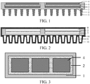
FIG. 1 is a sectional view of a structure of a heat dissipation element; -
FIG. 2 is a sectional view of an aluminizing mold and an inner structure of the aluminizing mold; and -
FIG. 3 is a top view of a heat dissipation element. - The following describes specific implementations of the present disclosure in detail with reference to the accompanying drawings. It should be understood that the specific implementations described herein are merely used to describe and explain the present disclosure, but are not intended to limit the present disclosure.
- A first aspect of the present disclosure provides a heat dissipation element. The heat dissipation element includes a heat conductor and a heat dissipation body, where the heat conductor is a ceramic-coated aluminum heat conductor; the heat dissipation body is an aluminum silicon carbon
heat dissipation body 1; the aluminum silicon carbonheat dissipation body 1 is provided with at least onegroove 6; and the ceramic-coated aluminum heat conductor is embedded into thegroove 6 through aluminizing in an integral forming manner. - In the foregoing technical solution, compared with a heat dissipation element obtained through vacuum welding, the heat dissipation element described in the present disclosure has fewer voids at a metal layer, higher strength, and a higher yield rate, and a service life is extended; the heat dissipation element has a thinner aluminum layer, thereby improving heat conduction efficiency of the heat dissipation element; there is no gap on bonding surfaces between layers of the heat dissipation element provided in the present disclosure, thereby having higher connection strength and higher heat conduction efficiency; in addition, a relatively soft ceramic-coated aluminum cover layer provides the heat dissipation apparatus with more excellent performance in coldness and heat impact tolerance; moreover, the present disclosure uses the foregoing aluminum silicon carbon heat dissipation body provided with a groove, and the ceramic-coated aluminum heat conductor is embedded into the groove through aluminizing in an integral forming manner, thereby avoiding a case in which an edge of a pasted film cracks during etching to affect an etching pattern, improving accuracy of etching, and improving strength and stability of the heat dissipation element.
- According to the first aspect of the present disclosure, preferably, as shown in
FIG. 1 , the ceramic-coated aluminum heat conductor includes aceramic insulating plate 2, and afirst aluminum layer 3 and asecond aluminum layer 4 that are integrally formed through aluminizing on two opposite surfaces of theceramic insulating plate 2, and thefirst aluminum layer 3 is adjacent to the aluminum silicon carbonheat dissipation body 1 and is bonded to the aluminum silicon carbonheat dissipation body 1. In other words, the ceramic-coated aluminum heat conductor includes a ceramicinsulating plate 2, and afirst aluminum layer 3 and asecond aluminum layer 4 that are disposed on two opposite surfaces of the ceramicinsulating plate 2, and the ceramicinsulating plate 2 is connected to the aluminum silicon carbonheat dissipation body 1 by using thefirst aluminum layer 3 that is integrally formed through aluminizing; the ceramicinsulating plate 2 isolates thesecond aluminum layer 4 from thefirst aluminum layer 3, and thesecond aluminum layer 4 is isolated from the aluminum silicon carbonheat dissipation body 1; thefirst aluminum layer 3 connects the aluminum silicon carbonheat dissipation body 1 and theceramic insulating plate 2 in an integral forming manner, so that there is no gap between the aluminum silicon carbonheat dissipation body 1 and theceramic insulating plate 2, thereby having better connection strength and extending a service life; and a circuit may be formed on thesecond aluminum layer 4 through etching. - According to the first aspect of the present disclosure, preferably, the ceramic
insulating plate 2 is an aluminum oxide ceramic plate, a toughened aluminum oxide ceramic plate, an aluminum nitride ceramic plate, or a silicon nitride ceramic plate. An upper surface of thesecond aluminum layer 4 and an upper surface, except thegroove 6, of the aluminum silicon carbonheat dissipation body 1 form a flat surface. Ceramic plates made of the foregoing materials have relatively low density and relatively high hardness, thereby helping extend a service life. The formed flat surface is conducive to pasting a film during subsequent etching, and prevents the pasted film from cracking, and etching is performed according to a presetting to improve accuracy of etching. - According to the first aspect of the present disclosure, preferably, a thickness of the
first aluminum layer 3 is 0.02 to 0.15 mm, a thickness of the ceramicinsulating plate 2 is 0.25 to 1 mm, and a thickness of thesecond aluminum layer 4 is 0.2 to 1.0 mm; and thefirst aluminum layer 3 and thesecond aluminum layer 4 are pure aluminum layers and/or aluminum alloy layers. The aluminum layer and the aluminum alloy layer can both satisfy heat conduction design of the heat dissipation apparatus, and the aluminum layer and the aluminum alloy layer have relatively low hardness and more excellent performance in coldness and heat impact tolerance. Therefore, use of the aluminum layer and theceramic insulating plate 2 of the described thicknesses may improve efficiency and structural strength of the ceramic-coated aluminum heat conductor, and extend a service life. - According to the first aspect of the present disclosure, preferably, the aluminum silicon carbon
heat dissipation body 1 is a silicon carbideporous skeleton 11 whose interior contains aluminum, where the aluminum is bonded to the interior of the silicon carbideporous skeleton 11 through aluminizing in an integral forming manner. In other words, the aluminum silicon carbonheat dissipation body 1 includes the silicon carbideporous skeleton 11 and the aluminum bonded to the interior of the silicon carbideporous skeleton 11 through aluminizing in an integral forming manner. The silicon carbide porous skeleton may integrally reinforce, along with the aluminum, structural strength of the aluminum silicon carbon heat dissipation body and connection strength of other components. - According to the first aspect of the present disclosure, preferably, as shown in
FIG. 1 , the aluminum silicon carbonheat dissipation body 1 is further provided with at least oneheat dissipation column 5 or one or moreheat dissipation columns 5; and one end of theheat dissipation column 5 is fixedly connected to the aluminum silicon carbonheat dissipation body 1, and the other end of theheat dissipation column 5 is a free end. Theheat dissipation column 5 is disposed on a surface, opposite to one side of the ceramic-coated aluminum heat conductor, of the aluminum silicon carbonheat dissipation body 1. Theheat dissipation column 5 can conduct heat radiated by an IGBT module, to improve heat dissipation efficiency. - According to the first aspect of the present disclosure, preferably, the
heat dissipation column 5 is at least one of an aluminum column, an aluminum alloy column, and an aluminum-coated copper column; theheat dissipation column 5 is connected to the aluminum silicon carbonheat dissipation body 1 through aluminizing in an integral forming manner; and connection strength between the integrally formedheat dissipation column 5 and the aluminum silicon carbonheat dissipation body 1 is higher, thereby reinforcing strength of the heat dissipation apparatus and extending a service life of the heat dissipation apparatus. - According to the first aspect of the present disclosure, relative to a same aluminum-silicon-carbon
heat dissipation body 1, onegroove 6 and one ceramicinsulating plate 2 are disposed, and at least onefirst aluminum layer 3 or one or morefirst aluminum layers 3 and at least onesecond aluminum layer 4 or one or moresecond aluminum layers 4 are disposed. - Alternatively, relative to a same aluminum-silicon-carbon
heat dissipation body 1, at least twogrooves 6 are disposed, and quantities offirst aluminum layers 3,second aluminum layers 4, and ceramicinsulating plates 2 that are disposed are each the same as a quantity of thegrooves 6. - Relative to a same aluminum silicon carbon
heat dissipation body 1, one groove and one ceramic insulating plate are disposed, there is onefirst aluminum layer 3 and one or moresecond aluminum layers 4, and the plurality ofsecond aluminum layers 4 are spaced apart from each other; alternatively, there are a plurality of grooves, and quantities offirst aluminum layers 3,second aluminum layers 4, and ceramicinsulating plates 2 are the same as a quantity of thegrooves 6. - The foregoing different settings of the
groove 6, the ceramic insulatingplate 2, thefirst aluminum layer 3, and thesecond aluminum layer 4 can satisfy different requirements for heat dissipation design. - A second aspect of the present disclosure provides a method for manufacturing a heat dissipation element. The method includes the following steps:
- S1. Mount a silicon carbide
porous skeleton 11 and a ceramic insulatingplate 2 into an aluminizing mold 10, the silicon carbideporous skeleton 11 being provided with at least onegroove 6 or one ormore grooves 6, the ceramic insulatingplate 2 being placed inside thegroove 6 of the silicon carbideporous skeleton 11, and enabling a first slot 7 to exist between a groove bottom of an aluminum silicon carbonheat dissipation body 1 and the ceramic insulatingplate 2, and asecond slot 8 to exist between the ceramic insulatingplate 2 and a wall of the aluminizing mold 10. - S2. Under pressure casting infiltration conditions, add molten aluminum liquid into the preheated aluminizing mold 10, and filling the first slot 7, the
second slot 8 and the silicon carbideporous skeleton 11 with the molten aluminum liquid, perform operations of vacuum pumping and pressurizing, and then perform cooling and demolding. - S3. Form an aluminum silicon carbon
heat dissipation body 1 after the interior of the silicon carbideporous skeleton 11 is filled with aluminum, and remove a part of aluminum metal in thesecond slot 8 by etching, to enable remaining aluminum metal in thesecond slot 8 to form asecond aluminum layer 4; and thesecond aluminum layer 4 and afirst aluminum layer 3 being isolated by the ceramic insulatingplate 2, and thesecond aluminum layer 4 being isolated from the aluminum silicon carbonheat dissipation body 1, as shown inFIG. 2 and FIG. 3 . - In the foregoing technical solution, according to the method for manufacturing the heat dissipation element provided in the present disclosure, molten aluminum liquid or aluminum alloy liquid is integrally formed to produce a ceramic-coated aluminum heat conductor, and the ceramic-coated aluminum heat conductor is connected to an aluminum silicon carbon
heat dissipation body 1. Three steps in a vacuum welding technology including manufacturing of the ceramic-coated aluminum heat conductor, processing on the aluminum silicon carbon heat dissipation body, and welding between the ceramic-coated aluminum heat conductor and the aluminum silicon carbonheat dissipation body 1 are combined into one step, thereby shortening a production period of the heat dissipation element; moreover, the ceramic insulatingplate 2 is placed inside agroove 6 of the aluminum silicon carbonheat dissipation body 1, so that it is easy to control a thickness of an aluminum layer on the surface of the ceramic-coated aluminum heat conductor, and the step simplifies the manufacturing process of the heat dissipation element. - The operation of providing the silicon carbide
porous skeleton 11 with one ormore grooves 6 may be implemented by using computer numerical control (CNC) machine tools. - According to the second aspect of the present disclosure, preferably, the pressure casting infiltration conditions include: a temperature of the preheating is 500 to 700□, a temperature of the molten aluminum liquid is 500 to 700□, a pressure of the vacuum pumping is 50 to 100 Pa, a pressure of the pressurizing is 4 to 10 MPa, and the molten aluminum liquid is pure aluminum or aluminum alloy. Pressure aluminizing in an integral forming manner under the conditions can reduce voids in the
first aluminum layer 3, thesecond aluminum layer 4, and a metal layer of theheat dissipation column 5, thereby improving production quality and a yield rate. - According to the second aspect of the present disclosure, preferably, the silicon carbide
porous skeleton 11 is mounted into the aluminizing mold 10, and an upper surface, on which thegroove 6 is formed, of the silicon carbideporous skeleton 11 is enabled to abut against an inner wall of the aluminizing mold 10, so that an upper surface of the formedsecond aluminum layer 4 and an upper surface of the obtained aluminum silicon carbonheat dissipation body 1 form a flat surface. In other words, a wall of the aluminizing mold 10 enables the upper surface of thesecond aluminum layer 4 and the upper surface, except thegroove 6, of the aluminum silicon carbonheat dissipation body 1 to form a flat surface. The formed flat surface is conducive to pasting a film during subsequent etching, and prevents the pasted film from cracking, and etching is performed according to a presetting to improve the accuracy of etching. - According to the second aspect of the present disclosure, preferably, at least one column-shaped recess 9 protruding outward is formed on an inner surface of the aluminizing
mold 11, and the column-shaped recess 9 is suitable for forming at least oneheat dissipation column 5 connected to the silicon carbideporous skeleton 11. In other words, a third slot 9 further exists between the silicon carbideporous skeleton 11 and a wall of the aluminizing mold 10. The third slot 9 is used to form theheat dissipation column 5. The third slot may be comb-tooth-shaped, and the tooth-shaped protrusion is used to form the heat dissipation column. In the method, theheat dissipation column 5 may form connection with the aluminum silicon carbonheat dissipation body 1 in a one-time manner, thereby avoiding subsequent melding of theheat dissipation column 5, and improving stability of the connection between theheat dissipation column 5 and the aluminum silicon carbonheat dissipation body 1. - According to the second aspect of the present disclosure, preferably, the ceramic insulating
plate 2 is an aluminum oxide ceramic plate, a toughened aluminum oxide ceramic plate, an aluminum nitride ceramic plate, or a silicon nitride ceramic plate; a thickness of thefirst aluminum layer 3 is 0.02 to 0.15 mm, a thickness of the ceramic insulatingplate 2 is 0.25 to 1 mm, and a thickness of thesecond aluminum layer 4 is 0.2 to 1 mm. Ceramic plates made of the foregoing materials have relatively low density and relatively high hardness, thereby helping extend a service life. Use of the aluminum layers with the described thicknesses and the ceramic insulatingplate 2 with the described thickness can improve heat conduction efficiency and structural strength of the ceramic-coated aluminum heat conductor, and extend the service life. - According to the second aspect of the present disclosure, relative to a same aluminum-silicon-carbon
heat dissipation body 1, onegroove 6 and one ceramic insulatingplate 2 are disposed, and at least onefirst aluminum layer 3 or one or morefirst aluminum layers 3 and at least onesecond aluminum layer 4 or one or moresecond aluminum layers 4 are disposed. - Alternatively, relative to a same aluminum-silicon-carbon
heat dissipation body 1, at least two or a plurality ofgrooves 6 are disposed, and quantities offirst aluminum layers 3,second aluminum layers 4, and ceramic insulatingplates 2 that are disposed are the same as a quantity of thegrooves 6. - Relative to a same aluminum silicon carbon
heat dissipation body 1, there may be one ceramic insulatingplate 2 and one groove, there is onefirst aluminum layer 3 and one or moresecond aluminum layers 4, and the plurality ofsecond aluminum layers 4 are connected to the ceramic insulatingplate 2 and are spaced apart from each other; alternatively, there are a plurality ofgrooves 6, and quantities offirst aluminum layers 3,second aluminum layers 4, and ceramic insulatingplates 2 are the same as a quantity of the grooves. - The foregoing different settings of the
groove 6, the ceramic insulatingplate 2, thefirst aluminum layer 3, and thesecond aluminum layer 4 can satisfy different requirements for heat dissipation design. - According to the second aspect of the present disclosure, preferably, etching may be performed by using various methods generally used by a person skilled in the art. A parameter may be a generally used parameter. For example, an etching operation includes sequentially performed steps of pasting a film, exposing, developing, corroding, removing the film, and washing.
- A third aspect of the present disclosure provides a heat dissipation element manufactured by using the foregoing method.
- A fourth aspect of the present disclosure provides an IGBT module. The IGBT module includes an IGBT circuit board and the heat dissipation element described above.
- The present disclosure is further described below by using embodiments, but the present disclosure is not limited thereto.
- This embodiment is used to describe a method for manufacturing a heat dissipation element.
- One silicon carbide
porous skeleton 11 having a thickness of 4.5 mm and three aluminum oxide ceramic insulatingplates 2 having a thickness of 0.38 mm, a length of 68 mm, and a width of 62 mm are mounted into an aluminizing mold 10, where the silicon carbideporous skeleton 11 has a length of 215 mm and a width of 110 mm; and the silicon carbideporous skeleton 11 is provided with threegrooves 6 having a depth of 0.93 mm, a length of 68 mm, and a width of 62 mm side by side by using computer numerical control (CNC) machine tools. An interval between each twoconsecutive grooves 6 is 6.9 mm. The ceramic insulatingplate 2 is placed inside thegroove 6, to enable a first slot 7 having a thickness of 0.1 mm to exist between a groove bottom of the silicon carbideporous skeleton 11 and the ceramic insulatingplate 2, and asecond slot 8 having a thickness of 0.5 mm to exist between the ceramic insulatingplate 2 and a wall of the aluminizing mold 10. A third slot 9 furthers exists between the wall of the aluminizing mold 10 and the silicon carbideporous skeleton 11, and is used to form aheat dissipation column 5. The third slot 9 is comb-tooth-shaped, and the tooth-shaped protrusion having a length of 8 mm is used to form theheat dissipation column 5. An interval between each two consecutive tooth-shaped protrusions is 0.8 mm. - The aluminizing mold 10 is preheated to have a temperature of 600□. Molten aluminum liquid of 700□ is added into the aluminizing mold 10. Vacuum pumping is performed until a pressure inside the aluminizing mold 10 is 80 Pa, and then pressurizing is performed until the pressure is 7 MPa. After the aluminum liquid is cooled to be of a room temperature and shaped, demolding is performed. The silicon carbide
porous skeleton 11 and the aluminum bonded to the interior of the silicon carbideporous skeleton 11 form an aluminum silicon carbonheat dissipation body 1. - A part of aluminum metal in the first slot 7 and the
second slot 8 is removed by etching after a film is pasted, so that remaining aluminum metal in the first slot 7 forms afirst aluminum layer 3 having a thickness of 0.1 mm, and remaining aluminum metal in thesecond slot 8 forms asecond aluminum layer 4 having a thickness of 0.45 mm. The ceramic insulatingplate 2 isolates thesecond aluminum layer 4 from thefirst aluminum layer 3, and thesecond aluminum layer 4 is isolated from the aluminum silicon carbonheat dissipation body 1. A slot of 1 mm exists between thesecond aluminum layer 4 and an edge of thegroove 6. - The heat dissipation element described in this embodiment is obtained after etching is completed.
- This embodiment is used to describe a method for manufacturing a heat dissipation element.
- One silicon carbide
porous skeleton 11 having a thickness of 4.5 mm and two toughened aluminum oxide ceramic insulatingplates 2 having a thickness of 0.32 mm, a length of 101 mm, and a width of 77 mm are mounted into an aluminizing mold 10, where the silicon carbideporous skeleton 11 has a length of 215 mm and a width of 110 mm; and the silicon carbideporous skeleton 11 is provided with twogrooves 6 having a depth of 0.87 mm, a length of 101 mm, and a width of 77 mm side by side by using computer numerical control (CNC) machine tools. An interval between each twoconsecutive grooves 6 is 6.9 mm. The ceramic insulatingplate 2 is placed inside thegroove 6, to enable a first slot 7 of 0.1 mm to exist between a groove bottom of the silicon carbideporous skeleton 11 and the ceramic insulatingplate 2, and asecond slot 8 of 0.5 mm to exist between the ceramic insulatingplate 2 and a wall of the aluminizing mold 10. A third slot 9 furthers exists between the wall of the aluminizing mold 10 and the silicon carbideporous skeleton 11, and is used to form aheat dissipation column 5. The third slot 9 is comb-tooth-shaped, and the tooth-shaped protrusion having a length of 8 mm is used to form theheat dissipation column 5. An interval between each two consecutive tooth-shaped protrusions is 0.8 mm. - The aluminizing mold 10 is preheated to have a temperature of 600□. Molten aluminum liquid of 700□ is added into the aluminizing mold 10. Vacuum pumping is performed until a pressure inside the aluminizing mold 10 is 80 Pa, and then pressurizing is performed until the pressure is 7 MPa. After the aluminum liquid is cooled to be of a room temperature and shaped, demolding is performed. The silicon carbide
porous skeleton 11 and the aluminum bonded to the interior of the silicon carbideporous skeleton 11 form an aluminum silicon carbonheat dissipation body 1. - A part of aluminum metal in the first slot 7 and the
second slot 8 is removed by etching after a film is pasted, so that remaining aluminum metal in the first slot 7 forms afirst aluminum layer 3 having a thickness of 0.1 mm, and remaining aluminum metal in thesecond slot 8 forms asecond aluminum layer 4 having a thickness of 0.45 mm. The ceramic insulatingplate 2 isolates thesecond aluminum layer 4 from thefirst aluminum layer 3, and thesecond aluminum layer 4 is isolated from the aluminum silicon carbonheat dissipation body 1. A slot of 1 mm exists between thesecond aluminum layer 4 and an edge of thegroove 6. - The heat dissipation element described in this embodiment is obtained after etching is completed.
- This embodiment is used to describe a method for manufacturing a heat dissipation element.
- One silicon carbide
porous skeleton 11 having a thickness of 4.5 mm and one aluminum nitrideceramic insulating plate 2 having a thickness of 0.63 mm, a length of 207.00 mm, and a width of 77 mm are mounted into an aluminizing mold 10, where the silicon carbideporous skeleton 11 has a length of 215 mm and a width of 110 mm; and the silicon carbideporous skeleton 11 is provided with onegroove 6 having a depth of 1.18 mm, a length of 207 mm, and a width of 77 mm by using computer numerical control (CNC) machine tools. The ceramic insulatingplate 2 is placed inside thegroove 6, to enable a first slot 7 of 0.1 mm to exist between a groove bottom of the silicon carbideporous skeleton 11 and the ceramic insulatingplate 2, and asecond slot 8 of 0.5 mm to exist between the ceramic insulatingplate 2 and a wall of the aluminizing mold 10. A third slot 9 furthers exists between the wall of the aluminizing mold 10 and the silicon carbideporous skeleton 11, and is used to form aheat dissipation column 5. The third slot 9 is comb-tooth-shaped, and the tooth-shaped protrusion having a length of 8 mm is used to form theheat dissipation column 5. An interval between each two consecutive tooth-shaped protrusions is 0.8 mm. - The aluminizing mold 10 is preheated to have a temperature of 600□. Molten aluminum liquid of 700□ is added into the aluminizing mold 10. Vacuum pumping is performed until a pressure inside the aluminizing mold 10 is 80 Pa, and then pressurizing is performed until the pressure is 7 MPa. After the aluminum liquid is cooled to be of a room temperature and shaped, demolding is performed. The silicon carbide
porous skeleton 11 and the aluminum bonded to the interior of the silicon carbideporous skeleton 11 form an aluminum silicon carbonheat dissipation body 1. - A part of aluminum metal in the first slot 7 and the
second slot 8 is removed by etching after a film is pasted, so that remaining aluminum metal in the first slot 7 forms afirst aluminum layer 3 having a thickness of 0.1 mm, and remaining aluminum metal in thesecond slot 8 forms threesecond aluminum layers 4 having a thickness of 0.45 mm, a length of 67.38 mm, and a width of 64 mm. There is an interval of 5 mm between the second aluminum layers 4. The ceramic insulatingplate 2 isolates thesecond aluminum layer 4 from thefirst aluminum layer 3, and thesecond aluminum layer 4 is isolated from the aluminum silicon carbonheat dissipation body 1. A slot of 1 mm exists between thesecond aluminum layer 4 and an edge of thegroove 6. - The heat dissipation element described in this embodiment is obtained after etching is completed.
- Silicon carbide particles and aluminum powder are mixed up and then are subject to cold press molding, hot pressing, annealing, and heat preservation to manufacture an aluminum silicon carbon heat dissipation body.
- A ceramic-coated copper heat conductor is preheated at a temperature of 185□ in hydrogen by using a solder of SnPbAg, and is welded to the aluminum silicon carbon heat dissipation body at a temperature of 265□ to manufacture a heat dissipation element of this comparative example. The ceramic-coated copper heat conductor includes an aluminum oxide ceramic insulating plate having a thickness of 0.32 mm, a first copper sheet having a thickness of 0.3 mm, and a second copper sheet having a thickness of 0.3 mm. The first copper sheet and the second copper sheet are oxidatively welded on two opposite surfaces of the ceramic insulating plate.
- A heat-cold cycling test is performed on heat dissipation elements obtained in
Embodiments 1 to 3 and Comparative Example 1. - The obtained heat dissipation elements are put into an ice-water mixture. After 30 minutes, the heat dissipation elements are taken out from the ice-water mixture (continuously adding ice cubes and keeping a 0□ environment). After being placed under a room temperature for 10 minutes, the heat dissipation elements are put into an oven of 150□. After being kept in 1500 for 30 minutes, the heat dissipation elements are taken out from the oven. After being placed at a room temperature for 10 minutes, the IGBT is put into the ice-water mixture (continuously adding ice cubes and keeping a 0□ environment) again by using a heat dissipation bottom plate. The foregoing process is a cycle. 20 heat dissipation elements in each group are separately subject to a performance measurement in coldness and heat impact tolerance. For every 20 cycles, a status (an appearance inspection, for example, a crack and a falling-off situation) of an aluminum layer of a to-be-measured sample is observed once. When the aluminum layer of the to-be-measured sample has an obvious crack and a falling-off tendency, the test for the to-be-measured sample is stopped. A quantity of times for which the to-be-measured sample has gone through the foregoing cycle so far is recorded, and an average of quantities of times for which the 20 to-be-measured heat dissipation elements in each group have gone through the cycle in the test is calculated. Measurement results of the foregoing heat dissipation elements of each group are shown in Table 1.
Table 1 Appearance after 100 cycles Quantity of times of coldness and heat impact tolerance Embodiment 1 Good 200 Embodiment 2Good 500 Embodiment 3Good 600 Comparative Example 1 A crack appears in a line slot 100 - It can be learned through comparison between
Embodiments 1 to 3 and Comparative Example 1 in Table 1 that, the heat dissipation element manufactured in the present disclosure has more excellent performance in coldness and heat impact tolerance, and has higher connection strength. - Exemplary implementations of the present disclosure are described above in detail with reference to the accompanying drawings. However, the present disclosure is not limited to specific details of the foregoing implementations. In the scope of the technical concept of the present disclosure, various simple variations may be made to the technical solutions of the present disclosure. These simple variations all fall within the protection scope of the present disclosure.
- In addition, it should be noted that the specific technical features described in the foregoing specific implementations may be combined in any appropriate manner if they are not contradictory. To avoid unnecessary repetition, various possible combination manners are not described again in the present disclosure.
- In addition, various different implementations of the present disclosure may be randomly combined. The combinations should also be considered as the content disclosed in the present disclosure provided that the combinations do not depart from the idea of the present disclosure.
| 1 | Aluminum silicon carbon | 2 | Ceramic |
| 3 | | 4 | |
| 5 | | 6 | Groove |
| 7 | | 8 | Second slot |
| 9 | Third slot | 10 | Aluminizing |
| 11 | Silicon carbide porous skeleton |
Claims (22)
- A heat dissipation element, comprising a heat conductor and a heat dissipation body, wherein the heat conductor is a ceramic-coated aluminum heat conductor; the heat dissipation body is an aluminum silicon carbon heat dissipation body (1); the aluminum silicon carbon heat dissipation body (1) is provided with at least one groove (6); and the ceramic-coated aluminum heat conductor is embedded into the groove (6) through aluminizing in an integral forming manner.
- The heat dissipation element according to claim 1, wherein the ceramic-coated aluminum heat conductor comprises a ceramic insulating plate (2), and a first aluminum layer (3) and a second aluminum layer (4) that are integrally formed through aluminizing on two opposite surfaces of the ceramic insulating plate (2), and the first aluminum layer (3) is adjacent to the aluminum silicon carbon heat dissipation body (1) and is bonded to the aluminum silicon carbon heat dissipation body (1).
- The heat dissipation element according to claim 2, wherein the ceramic insulating plate (2) is an aluminum oxide ceramic plate, a toughened aluminum oxide ceramic plate, an aluminum nitride ceramic plate, or a silicon nitride ceramic plate.
- The heat dissipation element according to claim 2 or 3, wherein an upper surface of the second aluminum layer (4) and an upper surface, except the groove (6), of the aluminum silicon carbon heat dissipation body (1) form a flat surface.
- The heat dissipation element according to any one of claims 2 to 4, wherein a thickness of the first aluminum layer (3) is 0.02 to 0.15 mm, a thickness of the ceramic insulating plate (2) is 0.25 to 1 mm, and a thickness of the second aluminum layer (4) is 0.2 to 1.0 mm.
- The heat dissipation element according to any one of claims 2 to 5, wherein the first aluminum layer (3) and the second aluminum layer (4) are pure aluminum layers and/or aluminum alloy layers.
- The heat dissipation element according to any one of claims 1 to 6, wherein the aluminum silicon carbon heat dissipation body (1) is a silicon carbide porous skeleton (11) whose interior contains aluminum.
- The heat dissipation element according to claim 7, wherein the aluminum is bonded to the interior of the silicon carbide porous skeleton (11) through aluminizing in an integral forming manner.
- The heat dissipation element according to any one of claims 1 to 8, wherein the aluminum silicon carbon heat dissipation body (1) is further provided with at least one heat dissipation column (5); one end of the heat dissipation column (5) is fixedly connected to the aluminum silicon carbon heat dissipation body (1), and the other end of the heat dissipation column (5) is a free end; and the heat dissipation column (5) is disposed on a surface, opposite to one side of the ceramic-coated aluminum heat conductor, of the aluminum silicon carbon heat dissipation body (1).
- The heat dissipation element according to claim 9, wherein the heat dissipation column (5) is at least one of an aluminum column, an aluminum alloy column, and an aluminum-coated copper column.
- The heat dissipation element according to claim 9 or 10, wherein the heat dissipation column (5) is connected to the aluminum silicon carbon heat dissipation body (1) through aluminizing in an integral forming manner.
- The heat dissipation element according to any one of claims 2 to 11, wherein relative to one aluminum-silicon-carbon heat dissipation body (1), there are one groove (6) and one ceramic insulating plate (2), and at least one first aluminum layer (3) and at least one second aluminum layer (4) are disposed;
Alternatively, relative to one aluminum-silicon-carbon heat dissipation body (1), at least two grooves (6) are disposed, and quantities of first aluminum layers (3), second aluminum layers (4), and ceramic insulating plates (2) that are disposed are each the same as a quantity of the grooves (6). - A method for manufacturing a heat dissipation element, wherein the method comprises the following steps:S1. mounting a silicon carbide porous skeleton (11) and a ceramic insulating plate (2) into an aluminizing mold (10), the silicon carbide porous skeleton (11) being provided with at least one groove (6), the ceramic insulating plate (2) being placed inside the groove (6), and enabling a first slot (7) to exist between a groove bottom of the silicon carbide porous skeleton (11) and the ceramic insulating plate (2), and a second slot (8) to exist between the ceramic insulating plate (2) and a wall of the aluminizing mold (10);S2. under pressure casting infiltration conditions, adding molten aluminum liquid into the preheated aluminizing mold (10), and filling the first slot (7), the second slot (8) and the silicon carbide porous skeleton (11) with the molten aluminum liquid, performing operations of vacuum pumping and pressurizing, and then performing cooling and demolding; andS3. forming an aluminum silicon carbon heat dissipation body (1) after the interior of the silicon carbide porous skeleton (11) is filled with aluminum, and removing a part of aluminum metal in the second slot (8) by etching, to enable remaining aluminum metal in the second slot (8) to form a second aluminum layer (4); and the second aluminum layer (4) and a first aluminum layer (3) being isolated by the ceramic insulating plate (2), and the second aluminum layer (4) being isolated from the aluminum silicon carbon heat dissipation body (1).
- The method according to claim 13, wherein the pressure casting infiltration conditions comprise: a temperature of the preheating is 500 to 700□, a temperature of the molten aluminum liquid is 500 to 700□, a pressure of the vacuum pumping is 50 to 100 Pa, a pressure of the pressurizing is 4 to 10 MPa, and the molten aluminum liquid is pure aluminum or aluminum alloy.
- The method according to claim 13 or 14, wherein the silicon carbide porous skeleton (11) is mounted into the aluminizing mold (10), and an upper surface, on which the groove (6) is formed, of the silicon carbide porous skeleton (11) is enabled to abut against an inner wall of the aluminizing mold (10), so that an upper surface of the formed second aluminum layer (4) and an upper surface of the obtained aluminum silicon carbon heat dissipation body (1) form a flat surface.
- The method according to any one of claims 13 to 15, wherein at least one column-shaped recess (9) protruding outward is formed on an inner surface of the aluminizing mold (10), and the column-shaped recess (9) is suitable for forming at least one heat dissipation column (5) connected to the silicon carbide porous skeleton (11).
- The method according to any one of claims 13 to 16, wherein the ceramic insulating plate (2) is selected from an aluminum oxide ceramic plate, a toughened aluminum oxide ceramic plate, an aluminum nitride ceramic plate, or a silicon nitride ceramic plate.
- The method according to any one of claims 13 to 17, wherein a thickness of the first aluminum layer (3) is 0.02 to 0.15 mm, a thickness of the ceramic insulating plate (2) is 0.25 to 1 mm, and a thickness of the second aluminum layer (4) is 0.2 to 1 mm.
- The method according to any one of claims 13 to 18, wherein relative to one aluminum-silicon-carbon heat dissipation body (1), one groove (6) and one ceramic insulating plate (2) are disposed, and at least one first aluminum layer (3) and at least one second aluminum layer (4) are disposed;
alternatively, relative to one aluminum-silicon-carbon heat dissipation body (1), at least two grooves (6) are disposed, and quantities of first aluminum layers (3), second aluminum layers (4), and ceramic insulating plates (2) that are disposed are each the same as a quantity of the grooves (6). - The method according to claim 13, wherein the etching comprises sequentially performed steps of pasting a film, exposing, developing, corroding, removing the film, and washing.
- A heat dissipation element manufactured by using the method according to any one of claims 13 to 20.
- An IGBT module, wherein the IGBT module comprises an IGBT circuit board and a heat dissipation element, and the heat dissipation element is the heat dissipation element according to any one of claims 1 to 12 and 21.
Applications Claiming Priority (2)
| Application Number | Priority Date | Filing Date | Title |
|---|---|---|---|
| CN201710626333.9A CN107546200B (en) | 2017-07-27 | 2017-07-27 | A kind of heat dissipation element and preparation method thereof and IGBT modules |
| PCT/CN2018/093610 WO2019019857A1 (en) | 2017-07-27 | 2018-06-29 | Heat dissipation element and preparation method therefor, and igbt module |
Publications (3)
| Publication Number | Publication Date |
|---|---|
| EP3660894A1 true EP3660894A1 (en) | 2020-06-03 |
| EP3660894A4 EP3660894A4 (en) | 2020-08-19 |
| EP3660894B1 EP3660894B1 (en) | 2025-01-15 |
Family
ID=60971079
Family Applications (1)
| Application Number | Title | Priority Date | Filing Date |
|---|---|---|---|
| EP18839408.4A Active EP3660894B1 (en) | 2017-07-27 | 2018-06-29 | Heat dissipation element and preparation method therefor, and igbt module |
Country Status (4)
| Country | Link |
|---|---|
| EP (1) | EP3660894B1 (en) |
| CN (1) | CN107546200B (en) |
| ES (1) | ES3012509T3 (en) |
| WO (1) | WO2019019857A1 (en) |
Families Citing this family (5)
| Publication number | Priority date | Publication date | Assignee | Title |
|---|---|---|---|---|
| CN107546200B (en) * | 2017-07-27 | 2018-09-11 | 比亚迪股份有限公司 | A kind of heat dissipation element and preparation method thereof and IGBT modules |
| CN107611104A (en) * | 2017-07-27 | 2018-01-19 | 比亚迪股份有限公司 | A kind of heat dissipation element and preparation method thereof and IGBT modules |
| CN111883493A (en) * | 2020-06-23 | 2020-11-03 | 西安理工大学 | IGBT module for electric automobile |
| CN114068333A (en) * | 2020-07-30 | 2022-02-18 | 比亚迪半导体股份有限公司 | Heat dissipation plate and preparation method thereof |
| CN111916412B (en) * | 2020-08-06 | 2022-07-12 | 互升科技(深圳)有限公司 | MOS (Metal oxide semiconductor) tube and preparation method thereof |
Family Cites Families (17)
| Publication number | Priority date | Publication date | Assignee | Title |
|---|---|---|---|---|
| JP2003078086A (en) * | 2001-09-04 | 2003-03-14 | Kubota Corp | Stacked structure of semiconductor element module substrate |
| US7521789B1 (en) * | 2004-12-18 | 2009-04-21 | Rinehart Motion Systems, Llc | Electrical assembly having heat sink protrusions |
| US7786486B2 (en) * | 2005-08-02 | 2010-08-31 | Satcon Technology Corporation | Double-sided package for power module |
| JP4378334B2 (en) * | 2005-09-09 | 2009-12-02 | 日本碍子株式会社 | Heat spreader module and manufacturing method thereof |
| WO2008123172A1 (en) * | 2007-03-27 | 2008-10-16 | Ngk Insulators, Ltd. | Heat spreader module, heat sink and method for manufacturing the heat spreader module and the heat sink |
| JP5619437B2 (en) * | 2010-03-12 | 2014-11-05 | Dowaメタルテック株式会社 | Method for producing metal / ceramic bonding substrate |
| JP2012195467A (en) * | 2011-03-17 | 2012-10-11 | Sansha Electric Mfg Co Ltd | Heat sink and manufacturing method of the same |
| JP6224960B2 (en) * | 2012-09-27 | 2017-11-01 | Dowaメタルテック株式会社 | Heat sink and manufacturing method thereof |
| JP5631446B2 (en) * | 2013-06-13 | 2014-11-26 | Dowaメタルテック株式会社 | Method for producing metal / ceramic bonding substrate |
| CN103521738B (en) * | 2013-10-17 | 2016-04-06 | 湖南航天工业总公司 | The quick aluminising device and method of silicon carbide IGBT substrate framework vacuum hydraulic pressure |
| CN204303795U (en) * | 2014-12-16 | 2015-04-29 | 湖南浩威特科技发展有限公司 | Aluminium silicon carbide base plate and there is the electronic device of this base plate |
| CN205430852U (en) * | 2015-11-30 | 2016-08-03 | 惠州比亚迪实业有限公司 | IGBT heat dissipation module and have its IGBT module |
| CN205414362U (en) * | 2016-03-29 | 2016-08-03 | 湖南浩威特科技发展有限公司 | Aluminium carborundum bottom plate and be used for mould of die -casting aluminium carborundum bottom plate |
| CN205464280U (en) * | 2016-04-07 | 2016-08-17 | 湖南浩威特科技发展有限公司 | A subassembly and curved surface radiating basal plate for die -casting curved surface radiating basal plate |
| CN106946583B (en) * | 2017-04-07 | 2023-03-21 | 西安明科微电子材料有限公司 | Preparation method of aluminum silicon carbide integrated substrate |
| CN107546200B (en) * | 2017-07-27 | 2018-09-11 | 比亚迪股份有限公司 | A kind of heat dissipation element and preparation method thereof and IGBT modules |
| CN207097805U (en) * | 2017-07-27 | 2018-03-13 | 比亚迪股份有限公司 | A kind of heat abstractor and IGBT module |
-
2017
- 2017-07-27 CN CN201710626333.9A patent/CN107546200B/en active Active
-
2018
- 2018-06-29 ES ES18839408T patent/ES3012509T3/en active Active
- 2018-06-29 WO PCT/CN2018/093610 patent/WO2019019857A1/en not_active Ceased
- 2018-06-29 EP EP18839408.4A patent/EP3660894B1/en active Active
Also Published As
| Publication number | Publication date |
|---|---|
| WO2019019857A1 (en) | 2019-01-31 |
| EP3660894B1 (en) | 2025-01-15 |
| CN107546200A (en) | 2018-01-05 |
| ES3012509T3 (en) | 2025-04-09 |
| EP3660894A4 (en) | 2020-08-19 |
| CN107546200B (en) | 2018-09-11 |
Similar Documents
| Publication | Publication Date | Title |
|---|---|---|
| EP3660895A1 (en) | Heat dissipating element and preparation method therefor, and igbt module | |
| EP3660894B1 (en) | Heat dissipation element and preparation method therefor, and igbt module | |
| CN104517917B (en) | Power semiconductor and the method for manufacturing power semiconductor | |
| CN107251214A (en) | Silicon nitride circuit substrate and the semiconductor module for having used the silicon nitride circuit substrate | |
| JP2019176152A (en) | Insulated circuit board with heat sink | |
| CN104551309A (en) | Target welding clamp and target welding method | |
| EP4425544A1 (en) | Integrated heat dissipation module structure | |
| US20100263848A1 (en) | Aluminum-Aluminum Nitride composite material, manufacturing method thereof and heat exchanger including the same | |
| US7207105B2 (en) | Method for producing an integral ceramic circuit board | |
| CN109309062A (en) | A kind of heat dissipation element and its preparation method and IGBT module | |
| CN116817648A (en) | Ceramic temperature equalizing plate and manufacturing method thereof | |
| JP6160937B2 (en) | Ceramic circuit board assembly and method for manufacturing ceramic circuit board | |
| CN114369750A (en) | Metal-based composite material and preparation method and application thereof | |
| TW201637153A (en) | Heat sink substrate | |
| WO2019019867A1 (en) | Heat dissipation element and preparation method therefor, and igbt module | |
| WO2019020019A1 (en) | Aluminum-copper clad-ceramic plate and preparation method therefor, heat dissipating element and igbt module | |
| CN114406260B (en) | Production process of high-reliability CPC composite material | |
| CN116798882A (en) | Manufacturing method of power module with double-sided heat dissipation structure | |
| CN103706797A (en) | Method for manufacturing wide multi-layer Cu-CuMo70-Cu composite materials | |
| CN116723679A (en) | Ceramic-based vapor chamber and preparation method and application thereof | |
| JP4674999B2 (en) | Integrated ceramic circuit board manufacturing method | |
| JP3871599B2 (en) | Structure | |
| JP2013225686A (en) | Method of manufacturing metal-ceramic junction substrate | |
| CN114874758A (en) | Novel indium-based efficient heat-conducting gasket | |
| CN115692216B (en) | Electronic packaging structure formed by compounding different materials and preparation method thereof |
Legal Events
| Date | Code | Title | Description |
|---|---|---|---|
| STAA | Information on the status of an ep patent application or granted ep patent |
Free format text: STATUS: THE INTERNATIONAL PUBLICATION HAS BEEN MADE |
|
| PUAI | Public reference made under article 153(3) epc to a published international application that has entered the european phase |
Free format text: ORIGINAL CODE: 0009012 |
|
| STAA | Information on the status of an ep patent application or granted ep patent |
Free format text: STATUS: REQUEST FOR EXAMINATION WAS MADE |
|
| 17P | Request for examination filed |
Effective date: 20200226 |
|
| AK | Designated contracting states |
Kind code of ref document: A1 Designated state(s): AL AT BE BG CH CY CZ DE DK EE ES FI FR GB GR HR HU IE IS IT LI LT LU LV MC MK MT NL NO PL PT RO RS SE SI SK SM TR |
|
| AX | Request for extension of the european patent |
Extension state: BA ME |
|
| A4 | Supplementary search report drawn up and despatched |
Effective date: 20200720 |
|
| RIC1 | Information provided on ipc code assigned before grant |
Ipc: C04B 37/00 20060101ALI20200714BHEP Ipc: H01L 23/367 20060101AFI20200714BHEP Ipc: H01L 23/373 20060101ALI20200714BHEP |
|
| DAV | Request for validation of the european patent (deleted) | ||
| DAX | Request for extension of the european patent (deleted) | ||
| STAA | Information on the status of an ep patent application or granted ep patent |
Free format text: STATUS: EXAMINATION IS IN PROGRESS |
|
| 17Q | First examination report despatched |
Effective date: 20220607 |
|
| GRAP | Despatch of communication of intention to grant a patent |
Free format text: ORIGINAL CODE: EPIDOSNIGR1 |
|
| STAA | Information on the status of an ep patent application or granted ep patent |
Free format text: STATUS: GRANT OF PATENT IS INTENDED |
|
| INTG | Intention to grant announced |
Effective date: 20240913 |
|
| GRAS | Grant fee paid |
Free format text: ORIGINAL CODE: EPIDOSNIGR3 |
|
| GRAA | (expected) grant |
Free format text: ORIGINAL CODE: 0009210 |
|
| STAA | Information on the status of an ep patent application or granted ep patent |
Free format text: STATUS: THE PATENT HAS BEEN GRANTED |
|
| AK | Designated contracting states |
Kind code of ref document: B1 Designated state(s): AL AT BE BG CH CY CZ DE DK EE ES FI FR GB GR HR HU IE IS IT LI LT LU LV MC MK MT NL NO PL PT RO RS SE SI SK SM TR |
|
| REG | Reference to a national code |
Ref country code: CH Ref legal event code: EP Ref country code: GB Ref legal event code: FG4D |
|
| REG | Reference to a national code |
Ref country code: DE Ref legal event code: R096 Ref document number: 602018078567 Country of ref document: DE |
|
| REG | Reference to a national code |
Ref country code: IE Ref legal event code: FG4D |
|
| REG | Reference to a national code |
Ref country code: NL Ref legal event code: FP |
|
| P01 | Opt-out of the competence of the unified patent court (upc) registered |
Free format text: CASE NUMBER: APP_9342/2025 Effective date: 20250225 |
|
| REG | Reference to a national code |
Ref country code: ES Ref legal event code: FG2A Ref document number: 3012509 Country of ref document: ES Kind code of ref document: T3 Effective date: 20250409 |
|
| PG25 | Lapsed in a contracting state [announced via postgrant information from national office to epo] |
Ref country code: RS Free format text: LAPSE BECAUSE OF FAILURE TO SUBMIT A TRANSLATION OF THE DESCRIPTION OR TO PAY THE FEE WITHIN THE PRESCRIBED TIME-LIMIT Effective date: 20250415 |
|
| PG25 | Lapsed in a contracting state [announced via postgrant information from national office to epo] |
Ref country code: FI Free format text: LAPSE BECAUSE OF FAILURE TO SUBMIT A TRANSLATION OF THE DESCRIPTION OR TO PAY THE FEE WITHIN THE PRESCRIBED TIME-LIMIT Effective date: 20250115 |
|
| PG25 | Lapsed in a contracting state [announced via postgrant information from national office to epo] |
Ref country code: PL Free format text: LAPSE BECAUSE OF FAILURE TO SUBMIT A TRANSLATION OF THE DESCRIPTION OR TO PAY THE FEE WITHIN THE PRESCRIBED TIME-LIMIT Effective date: 20250115 |
|
| PGFP | Annual fee paid to national office [announced via postgrant information from national office to epo] |
Ref country code: DE Payment date: 20250618 Year of fee payment: 8 |
|
| PGFP | Annual fee paid to national office [announced via postgrant information from national office to epo] |
Ref country code: GB Payment date: 20250618 Year of fee payment: 8 |
|
| REG | Reference to a national code |
Ref country code: LT Ref legal event code: MG9D |
|
| PG25 | Lapsed in a contracting state [announced via postgrant information from national office to epo] |
Ref country code: IS Free format text: LAPSE BECAUSE OF FAILURE TO SUBMIT A TRANSLATION OF THE DESCRIPTION OR TO PAY THE FEE WITHIN THE PRESCRIBED TIME-LIMIT Effective date: 20250515 Ref country code: NO Free format text: LAPSE BECAUSE OF FAILURE TO SUBMIT A TRANSLATION OF THE DESCRIPTION OR TO PAY THE FEE WITHIN THE PRESCRIBED TIME-LIMIT Effective date: 20250415 |
|
| PGFP | Annual fee paid to national office [announced via postgrant information from national office to epo] |
Ref country code: NL Payment date: 20250618 Year of fee payment: 8 |
|
| REG | Reference to a national code |
Ref country code: AT Ref legal event code: MK05 Ref document number: 1760410 Country of ref document: AT Kind code of ref document: T Effective date: 20250115 |
|
| PG25 | Lapsed in a contracting state [announced via postgrant information from national office to epo] |
Ref country code: HR Free format text: LAPSE BECAUSE OF FAILURE TO SUBMIT A TRANSLATION OF THE DESCRIPTION OR TO PAY THE FEE WITHIN THE PRESCRIBED TIME-LIMIT Effective date: 20250115 |
|
| PG25 | Lapsed in a contracting state [announced via postgrant information from national office to epo] |
Ref country code: PT Free format text: LAPSE BECAUSE OF FAILURE TO SUBMIT A TRANSLATION OF THE DESCRIPTION OR TO PAY THE FEE WITHIN THE PRESCRIBED TIME-LIMIT Effective date: 20250515 Ref country code: LV Free format text: LAPSE BECAUSE OF FAILURE TO SUBMIT A TRANSLATION OF THE DESCRIPTION OR TO PAY THE FEE WITHIN THE PRESCRIBED TIME-LIMIT Effective date: 20250115 |
|
| PGFP | Annual fee paid to national office [announced via postgrant information from national office to epo] |
Ref country code: FR Payment date: 20250626 Year of fee payment: 8 |
|
| PG25 | Lapsed in a contracting state [announced via postgrant information from national office to epo] |
Ref country code: BG Free format text: LAPSE BECAUSE OF FAILURE TO SUBMIT A TRANSLATION OF THE DESCRIPTION OR TO PAY THE FEE WITHIN THE PRESCRIBED TIME-LIMIT Effective date: 20250115 Ref country code: GR Free format text: LAPSE BECAUSE OF FAILURE TO SUBMIT A TRANSLATION OF THE DESCRIPTION OR TO PAY THE FEE WITHIN THE PRESCRIBED TIME-LIMIT Effective date: 20250416 |
|
| PG25 | Lapsed in a contracting state [announced via postgrant information from national office to epo] |
Ref country code: AT Free format text: LAPSE BECAUSE OF FAILURE TO SUBMIT A TRANSLATION OF THE DESCRIPTION OR TO PAY THE FEE WITHIN THE PRESCRIBED TIME-LIMIT Effective date: 20250115 |
|
| PG25 | Lapsed in a contracting state [announced via postgrant information from national office to epo] |
Ref country code: SE Free format text: LAPSE BECAUSE OF FAILURE TO SUBMIT A TRANSLATION OF THE DESCRIPTION OR TO PAY THE FEE WITHIN THE PRESCRIBED TIME-LIMIT Effective date: 20250115 |
|
| PG25 | Lapsed in a contracting state [announced via postgrant information from national office to epo] |
Ref country code: SM Free format text: LAPSE BECAUSE OF FAILURE TO SUBMIT A TRANSLATION OF THE DESCRIPTION OR TO PAY THE FEE WITHIN THE PRESCRIBED TIME-LIMIT Effective date: 20250115 |
|
| PGFP | Annual fee paid to national office [announced via postgrant information from national office to epo] |
Ref country code: ES Payment date: 20250731 Year of fee payment: 8 |
|
| PG25 | Lapsed in a contracting state [announced via postgrant information from national office to epo] |
Ref country code: DK Free format text: LAPSE BECAUSE OF FAILURE TO SUBMIT A TRANSLATION OF THE DESCRIPTION OR TO PAY THE FEE WITHIN THE PRESCRIBED TIME-LIMIT Effective date: 20250115 |
|
| PGFP | Annual fee paid to national office [announced via postgrant information from national office to epo] |
Ref country code: IT Payment date: 20250624 Year of fee payment: 8 |
|
| REG | Reference to a national code |
Ref country code: DE Ref legal event code: R097 Ref document number: 602018078567 Country of ref document: DE |
|
| PG25 | Lapsed in a contracting state [announced via postgrant information from national office to epo] |
Ref country code: CZ Free format text: LAPSE BECAUSE OF FAILURE TO SUBMIT A TRANSLATION OF THE DESCRIPTION OR TO PAY THE FEE WITHIN THE PRESCRIBED TIME-LIMIT Effective date: 20250115 Ref country code: EE Free format text: LAPSE BECAUSE OF FAILURE TO SUBMIT A TRANSLATION OF THE DESCRIPTION OR TO PAY THE FEE WITHIN THE PRESCRIBED TIME-LIMIT Effective date: 20250115 |
|
| PG25 | Lapsed in a contracting state [announced via postgrant information from national office to epo] |
Ref country code: RO Free format text: LAPSE BECAUSE OF FAILURE TO SUBMIT A TRANSLATION OF THE DESCRIPTION OR TO PAY THE FEE WITHIN THE PRESCRIBED TIME-LIMIT Effective date: 20250115 |
|
| PG25 | Lapsed in a contracting state [announced via postgrant information from national office to epo] |
Ref country code: SK Free format text: LAPSE BECAUSE OF FAILURE TO SUBMIT A TRANSLATION OF THE DESCRIPTION OR TO PAY THE FEE WITHIN THE PRESCRIBED TIME-LIMIT Effective date: 20250115 |
|
| PLBE | No opposition filed within time limit |
Free format text: ORIGINAL CODE: 0009261 |
|
| STAA | Information on the status of an ep patent application or granted ep patent |
Free format text: STATUS: NO OPPOSITION FILED WITHIN TIME LIMIT |
|
| REG | Reference to a national code |
Ref country code: CH Ref legal event code: L10 Free format text: ST27 STATUS EVENT CODE: U-0-0-L10-L00 (AS PROVIDED BY THE NATIONAL OFFICE) Effective date: 20251126 |
|
| REG | Reference to a national code |
Ref country code: DE Ref legal event code: R079 Ref document number: 602018078567 Country of ref document: DE Free format text: PREVIOUS MAIN CLASS: H01L0023367000 Ipc: H10W0040220000 |
|
| 26N | No opposition filed |
Effective date: 20251016 |
|
| REG | Reference to a national code |
Ref country code: CH Ref legal event code: H13 Free format text: ST27 STATUS EVENT CODE: U-0-0-H10-H13 (AS PROVIDED BY THE NATIONAL OFFICE) Effective date: 20260127 |
|
| PG25 | Lapsed in a contracting state [announced via postgrant information from national office to epo] |
Ref country code: MC Free format text: LAPSE BECAUSE OF FAILURE TO SUBMIT A TRANSLATION OF THE DESCRIPTION OR TO PAY THE FEE WITHIN THE PRESCRIBED TIME-LIMIT Effective date: 20250115 |
|
| PG25 | Lapsed in a contracting state [announced via postgrant information from national office to epo] |
Ref country code: LU Free format text: LAPSE BECAUSE OF NON-PAYMENT OF DUE FEES Effective date: 20250629 |
|
| REG | Reference to a national code |
Ref country code: BE Ref legal event code: MM Effective date: 20250630 |
|
| PG25 | Lapsed in a contracting state [announced via postgrant information from national office to epo] |
Ref country code: IE Free format text: LAPSE BECAUSE OF NON-PAYMENT OF DUE FEES Effective date: 20250629 |
|
| PG25 | Lapsed in a contracting state [announced via postgrant information from national office to epo] |
Ref country code: BE Free format text: LAPSE BECAUSE OF NON-PAYMENT OF DUE FEES Effective date: 20250630 |
|
| PG25 | Lapsed in a contracting state [announced via postgrant information from national office to epo] |
Ref country code: CH Free format text: LAPSE BECAUSE OF NON-PAYMENT OF DUE FEES Effective date: 20250630 |