EP3660515A1 - Optical disc device, optical disc rotation position detection method, and optical disc - Google Patents
Optical disc device, optical disc rotation position detection method, and optical disc Download PDFInfo
- Publication number
- EP3660515A1 EP3660515A1 EP19211309.0A EP19211309A EP3660515A1 EP 3660515 A1 EP3660515 A1 EP 3660515A1 EP 19211309 A EP19211309 A EP 19211309A EP 3660515 A1 EP3660515 A1 EP 3660515A1
- Authority
- EP
- European Patent Office
- Prior art keywords
- optical disc
- reference mark
- rotation
- rotation reference
- optical
- Prior art date
- Legal status (The legal status is an assumption and is not a legal conclusion. Google has not performed a legal analysis and makes no representation as to the accuracy of the status listed.)
- Withdrawn
Links
Images




Classifications
-
- G—PHYSICS
- G06—COMPUTING OR CALCULATING; COUNTING
- G06F—ELECTRIC DIGITAL DATA PROCESSING
- G06F3/00—Input arrangements for transferring data to be processed into a form capable of being handled by the computer; Output arrangements for transferring data from processing unit to output unit, e.g. interface arrangements
- G06F3/06—Digital input from, or digital output to, record carriers, e.g. RAID, emulated record carriers or networked record carriers
- G06F3/0601—Interfaces specially adapted for storage systems
- G06F3/0628—Interfaces specially adapted for storage systems making use of a particular technique
- G06F3/0629—Configuration or reconfiguration of storage systems
- G06F3/0634—Configuration or reconfiguration of storage systems by changing the state or mode of one or more devices
-
- G—PHYSICS
- G11—INFORMATION STORAGE
- G11B—INFORMATION STORAGE BASED ON RELATIVE MOVEMENT BETWEEN RECORD CARRIER AND TRANSDUCER
- G11B19/00—Driving, starting, stopping record carriers not specifically of filamentary or web form, or of supports therefor; Control thereof; Control of operating function ; Driving both disc and head
- G11B19/02—Control of operating function, e.g. switching from recording to reproducing
- G11B19/12—Control of operating function, e.g. switching from recording to reproducing by sensing distinguishing features of or on records, e.g. diameter end mark
- G11B19/122—Control of operating function, e.g. switching from recording to reproducing by sensing distinguishing features of or on records, e.g. diameter end mark involving the detection of an identification or authentication mark
-
- G—PHYSICS
- G01—MEASURING; TESTING
- G01N—INVESTIGATING OR ANALYSING MATERIALS BY DETERMINING THEIR CHEMICAL OR PHYSICAL PROPERTIES
- G01N35/00—Automatic analysis not limited to methods or materials provided for in any single one of groups G01N1/00 - G01N33/00; Handling materials therefor
- G01N35/00029—Automatic analysis not limited to methods or materials provided for in any single one of groups G01N1/00 - G01N33/00; Handling materials therefor provided with flat sample substrates, e.g. slides
- G01N35/00069—Automatic analysis not limited to methods or materials provided for in any single one of groups G01N1/00 - G01N33/00; Handling materials therefor provided with flat sample substrates, e.g. slides whereby the sample substrate is of the bio-disk type, i.e. having the format of an optical disk
-
- G—PHYSICS
- G11—INFORMATION STORAGE
- G11B—INFORMATION STORAGE BASED ON RELATIVE MOVEMENT BETWEEN RECORD CARRIER AND TRANSDUCER
- G11B17/00—Guiding record carriers not specifically of filamentary or web form, or of supports therefor
- G11B17/02—Details
- G11B17/022—Positioning or locking of single discs
- G11B17/028—Positioning or locking of single discs of discs rotating during transducing operation
-
- G—PHYSICS
- G06—COMPUTING OR CALCULATING; COUNTING
- G06F—ELECTRIC DIGITAL DATA PROCESSING
- G06F3/00—Input arrangements for transferring data to be processed into a form capable of being handled by the computer; Output arrangements for transferring data from processing unit to output unit, e.g. interface arrangements
- G06F3/06—Digital input from, or digital output to, record carriers, e.g. RAID, emulated record carriers or networked record carriers
- G06F3/0601—Interfaces specially adapted for storage systems
- G06F3/0602—Interfaces specially adapted for storage systems specifically adapted to achieve a particular effect
- G06F3/0604—Improving or facilitating administration, e.g. storage management
- G06F3/0607—Improving or facilitating administration, e.g. storage management by facilitating the process of upgrading existing storage systems, e.g. for improving compatibility between host and storage device
-
- G—PHYSICS
- G06—COMPUTING OR CALCULATING; COUNTING
- G06F—ELECTRIC DIGITAL DATA PROCESSING
- G06F3/00—Input arrangements for transferring data to be processed into a form capable of being handled by the computer; Output arrangements for transferring data from processing unit to output unit, e.g. interface arrangements
- G06F3/06—Digital input from, or digital output to, record carriers, e.g. RAID, emulated record carriers or networked record carriers
- G06F3/0601—Interfaces specially adapted for storage systems
- G06F3/0668—Interfaces specially adapted for storage systems adopting a particular infrastructure
- G06F3/0671—In-line storage system
- G06F3/0673—Single storage device
- G06F3/0674—Disk device
- G06F3/0677—Optical disk device, e.g. CD-ROM, DVD
-
- G—PHYSICS
- G11—INFORMATION STORAGE
- G11B—INFORMATION STORAGE BASED ON RELATIVE MOVEMENT BETWEEN RECORD CARRIER AND TRANSDUCER
- G11B27/00—Editing; Indexing; Addressing; Timing or synchronising; Monitoring; Measuring tape travel
- G11B27/10—Indexing; Addressing; Timing or synchronising; Measuring tape travel
- G11B27/19—Indexing; Addressing; Timing or synchronising; Measuring tape travel by using information detectable on the record carrier
-
- G—PHYSICS
- G11—INFORMATION STORAGE
- G11B—INFORMATION STORAGE BASED ON RELATIVE MOVEMENT BETWEEN RECORD CARRIER AND TRANSDUCER
- G11B7/00—Recording or reproducing by optical means, e.g. recording using a thermal beam of optical radiation by modifying optical properties or the physical structure, reproducing using an optical beam at lower power by sensing optical properties; Record carriers therefor
- G11B7/002—Recording, reproducing or erasing systems characterised by the shape or form of the carrier
- G11B7/0037—Recording, reproducing or erasing systems characterised by the shape or form of the carrier with discs
-
- G—PHYSICS
- G11—INFORMATION STORAGE
- G11B—INFORMATION STORAGE BASED ON RELATIVE MOVEMENT BETWEEN RECORD CARRIER AND TRANSDUCER
- G11B7/00—Recording or reproducing by optical means, e.g. recording using a thermal beam of optical radiation by modifying optical properties or the physical structure, reproducing using an optical beam at lower power by sensing optical properties; Record carriers therefor
- G11B7/24—Record carriers characterised by shape, structure or physical properties, or by the selection of the material
-
- G—PHYSICS
- G11—INFORMATION STORAGE
- G11B—INFORMATION STORAGE BASED ON RELATIVE MOVEMENT BETWEEN RECORD CARRIER AND TRANSDUCER
- G11B7/00—Recording or reproducing by optical means, e.g. recording using a thermal beam of optical radiation by modifying optical properties or the physical structure, reproducing using an optical beam at lower power by sensing optical properties; Record carriers therefor
- G11B7/24—Record carriers characterised by shape, structure or physical properties, or by the selection of the material
- G11B7/24094—Indication parts or information parts for identification
-
- G—PHYSICS
- G11—INFORMATION STORAGE
- G11B—INFORMATION STORAGE BASED ON RELATIVE MOVEMENT BETWEEN RECORD CARRIER AND TRANSDUCER
- G11B7/00—Recording or reproducing by optical means, e.g. recording using a thermal beam of optical radiation by modifying optical properties or the physical structure, reproducing using an optical beam at lower power by sensing optical properties; Record carriers therefor
- G11B7/24—Record carriers characterised by shape, structure or physical properties, or by the selection of the material
- G11B7/24097—Structures for detection, control, recording operation or replay operation; Special shapes or structures for centering or eccentricity prevention; Arrangements for testing, inspecting or evaluating; Containers, cartridges or cassettes
-
- G—PHYSICS
- G11—INFORMATION STORAGE
- G11B—INFORMATION STORAGE BASED ON RELATIVE MOVEMENT BETWEEN RECORD CARRIER AND TRANSDUCER
- G11B7/00—Recording or reproducing by optical means, e.g. recording using a thermal beam of optical radiation by modifying optical properties or the physical structure, reproducing using an optical beam at lower power by sensing optical properties; Record carriers therefor
- G11B7/24—Record carriers characterised by shape, structure or physical properties, or by the selection of the material
- G11B2007/240004—Record carriers characterised by shape, structure or physical properties, or by the selection of the material characterised by the form of the carrier
- G11B2007/240008—Cards
- G11B2007/240012—Cards intended for rotation
-
- G—PHYSICS
- G11—INFORMATION STORAGE
- G11B—INFORMATION STORAGE BASED ON RELATIVE MOVEMENT BETWEEN RECORD CARRIER AND TRANSDUCER
- G11B2220/00—Record carriers by type
- G11B2220/20—Disc-shaped record carriers
- G11B2220/25—Disc-shaped record carriers characterised in that the disc is based on a specific recording technology
- G11B2220/2537—Optical discs
-
- G—PHYSICS
- G11—INFORMATION STORAGE
- G11B—INFORMATION STORAGE BASED ON RELATIVE MOVEMENT BETWEEN RECORD CARRIER AND TRANSDUCER
- G11B7/00—Recording or reproducing by optical means, e.g. recording using a thermal beam of optical radiation by modifying optical properties or the physical structure, reproducing using an optical beam at lower power by sensing optical properties; Record carriers therefor
- G11B7/007—Arrangement of the information on the record carrier, e.g. form of tracks, actual track shape, e.g. wobbled, or cross-section, e.g. v-shaped; Sequential information structures, e.g. sectoring or header formats within a track
Definitions
- the present disclosure relates to an optical disc device, an optical disc rotation position detection method, and an optical disc.
- Patent Document 1 Japanese Translation of PCT International Application Publication No. 2002-521666 (hereinafter referred to as Patent Document 1) and Japanese Patent Application Publication No. 2006-322819 (hereinafter referred to as Patent Document 2) disclose an optical disc device in which antibodies that are fixed to a reaction region on an optical disc are allowed to bind to antigens in a sample, so that the antigens are labeled by nanoparticles having antibodies.
- the optical disc device scans and detects the nanoparticles captured on the reaction region on the optical disc with laser light emitted from an optical pickup.
- the optical disc device disclosed in Patent Documents 1 and 2 serves as an analysis device for detecting a specimen.
- the optical disc device moves the optical pickup in a radial direction of the optical disc being rotated. Since the optical disc is provided thereon with a plurality of reaction regions, a reaction region in which nanoparticles are detected needs to be specified.
- the optical disc device disclosed in Patent Document 1 specifies a corresponding reaction region by use of address information of the optical disc.
- Patent Document 2 discloses that the optical disc includes a group of pits in which positional information on reaction regions is recorded.
- the optical disc device as disclosed in Patent Documents 1 and 2 thus needs to preliminarily record the address information for specifying the positions of the reaction regions on the optical disc. This complicates the process of manufacturing the optical disc, increasing manufacturing costs of the optical disc accordingly.
- the present disclosure provides an optical disc device, an optical disc rotation position detection method, and an optical disc capable of facilitating a detection of a reference position on the optical disc in a rotating direction regardless of whether address information is recorded in the optical disc.
- a first aspect of one or more embodiments provides an optical disc device including: an optical disc rotation drive unit configured to rotate an optical disc provided with a rotation reference mark; an optical sensor configured to detect the rotation reference mark; and a control circuit configured to control the optical disc rotation drive unit and the optical sensor, the rotation reference mark being formed into a shape having a width changing in a radial direction of the optical disc, the control circuit being configured to extract a detection signal of the rotation reference mark as a pulse waveform from an output signal of the optical sensor with the optical disc being rotated, and specify a rotation reference position of the optical disc in accordance with the pulse waveform.
- a second aspect of one or more embodiments provides an optical disc rotation position detection method including: causing an optical disc rotation drive unit to rotate an optical disc provided with a rotation reference mark formed into a shape having a width changing in a radial direction of the optical disc; causing an optical sensor to detect the rotation reference mark; and causing a control circuit to extract a detection signal of the rotation reference mark as a pulse waveform from an output signal of the optical sensor with the optical disc being rotated, and specify a rotation reference position of the optical disc in accordance with the pulse waveform.
- a third aspect of one or more embodiments provides an optical disc including a rotation reference mark for specifying a rotation reference position of the optical disc, the rotation reference mark being formed into a shape having a width changing in a radial direction of the optical disc.
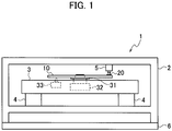
- the optical disc device 1 includes a casing 2, a traverse mechanism 3, a damping member 4, an optical sensor 5, and a control circuit 6.
- the traverse mechanism 3 is housed and fixed to the casing 2 via the damping member 4.
- a damper rubber may be used as the damping member 4.
- the damping member 4 absorbs oscillation of the casing 2 to avoid further propagation of the oscillation to the traverse mechanism 3.
- the optical sensor 5 is fixed to the casing 2.
- the control circuit 6 is electrically connected to the traverse mechanism 3 and the optical sensor 5.
- the control circuit 6 controls the traverse mechanism 3 and the optical sensor 5.
- An optical disc drive circuit board may be used as the control circuit 6.
- the traverse mechanism 3 includes a turntable 31, a rotation drive unit 32, and an optical pickup 33.
- a motor may be used as the rotation drive unit 32.
- the control circuit 6 controls to cause the traverse mechanism 3 to move and set an optical disc 10 onto the turntable 31, or remove the optical disc 10 set on the turntable 31 from the traverse mechanism 3.
- the traverse mechanism 3 rotates the turntable 31 at a predetermined rotation rate or at a constant angular velocity, or moves the optical pickup 33 to a predetermined position in the radial direction of the optical disc 10.
- the traverse mechanism 3 rotates the turntable 31 to serve as an optical disc rotation drive unit for rotating the optical disc 10.
- the traverse mechanism 3 can adjust a focal point of laser light emitted to the optical disc 10 from the optical pickup 33.
- the optical disc 10 has a first surface 10a, a second surface 10b, and a central hole 11.
- the center C11 of the central hole 11 conforms to the rotational center C10 of the optical disc 10.
- the first surface 10a is provided with a rotation reference mark 20.
- the rotation reference mark 20 is preferably located at or around the circumference of the optical disc 10.
- the optical sensor 5 is arranged at a position capable of detecting the rotation reference mark 20.
- the second surface 10b on the opposite side of the first surface 10a is provided with tracks for recording and reading out pieces of information, or provided with reaction regions.
- reaction region refers to a region in which antigens as detection target substances are to be captured and sandwiched between antibodies fixed to the optical disc 10 and nanoparticles.
- the detection target substances and the nanoparticles sometimes are not captured in some of the reaction regions.
- the reaction regions are used for capturing the detection target substances and the nanoparticles.
- the optical pickup 33 is movably positioned within a range capable of recording and reading out pieces of information or within a range capable of detecting the reaction regions in the radial direction of the optical disc 10.
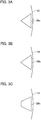
- Fig. 3A is an enlarged view of the rotation reference mark 20 shown in Fig. 2A .
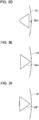
- Fig. 3B to Fig. 3J are views showing other examples of the rotation reference mark 20.
- the respective rotation reference marks are indicated by the reference numerals 20a to 20j corresponding to Fig. 3A to Fig. 3J .
- the rotation reference mark 20a shown in Fig. 3A has a triangular shape with a width increasing from the inner circumference to the outer circumference of the optical disc 10.
- the rotation reference mark 20b shown in Fig. 3B has a sector-like shape with a width increasing from the inner circumference to the outer circumference of the optical disc 10.
- the rotation reference mark 20c shown in Fig. 3C has a trapezoidal shape with a width increasing from the inner circumference to the outer circumference of the optical disc 10.
- the rotation reference mark 20d shown in Fig. 3D has a shape with a width increasing from the inner circumference to the outer circumference of the optical disc 10, having two acute-angled parts and one U-shaped part.
- the rotation reference mark 20e shown in Fig. 3E has a triangular shape with a width decreasing from the inner circumference to the outer circumference of the optical disc 10.
- the rotation reference mark 20f shown in Fig. 3F has a sector-like shape with a width decreasing from the inner circumference to the outer circumference of the optical disc 10.
- the rotation reference mark 20g shown in Fig. 3G has a trapezoidal shape with a width decreasing from the inner circumference to the outer circumference of the optical disc 10.
- the rotation reference mark 20h shown in Fig. 3H has a shape with a width decreasing from the inner circumference to the outer circumference of the optical disc 10, having two acute-angled parts and one U-shaped part.
- the rotation reference mark 20i shown in Fig. 3I includes a plurality of patterns 20ia to 20ic arranged at intervals along the periphery (in the circumferential direction) of the optical disc 10, the respective intervals changing in width in the radial direction of the optical disc 10.
- the respective patterns 20ia to 20ic are formed into a rectangular strip, for example, with the intervals gradually widened from the inner circumference to the outer circumference of the optical disc 10.
- the rotation reference mark 20i thus entirely has a shape with a width increasing from the inner circumference to the outer circumference of the optical disc 10.
- the rotation reference mark 20j shown in Fig. 3J includes a plurality of patterns 20ja to 20jc arranged at intervals along the periphery (in the circumferential direction) of the optical disc 10, the respective intervals changing in width in the radial direction of the optical disc 10.
- the respective patterns 20ja to 20jc are formed into a rectangular strip, for example, with the intervals tapering from the inner circumference to the outer circumference of the optical disc 10.
- the rotation reference mark 20j thus entirely has a shape with a width decreasing from the inner circumference to the outer circumference of the optical disc 10.
- the respective rotation reference marks 20a to 20j are common in that the width changes in the radial direction of the optical disc 10.
- the rotation reference mark 20 thus has a shape with a width changing in the radial direction of the optical disc 10.
- the rotation reference mark 20 (20a to 20j) may be either in contact with or separated from the outer circumferential edge of the optical disc 10.
- the rotation reference mark 20 (20a to 20j) may be formed such that a reflective film (such as an aluminum film) is coated on the first surface 10a of the optical disc 10 (by vapor deposition, for example) and is then subj ected to patterning by photolithography.
- the rotation reference mark 20 (20a to 20j) may be formed such that a reflective film (such as an aluminum film) is coated on the first surface 10a of the optical disc 10 by masking and patterning (by vapor deposition, for example).
- the rotation reference mark 20 (20a to 20j) may be formed such that a reflective member may be printed or applied into a predetermined shape on the first surface 10a of the optical disc 10, or a reflective member having a predetermined shape may be bonded to the first surface 10a of the optical disc 10.
- the reflective film or the reflective member is only required to be made of a material having optical reflectivity.
- Detecting the position of the optical pickup 33 can specify the position on the optical disc 10 in the radial direction when the optical disc 10 has no address information.
- a reference position on the optical disc 10 in the rotating direction still needs to be detected in order to specify the position on the optical disc 10 in the track direction when having no address information.
- the traverse mechanism 3 is fixed to the casing 2 via the damping member 4, so as to block off the propagation of oscillation of the casing 2 to the traverse mechanism 3.
- the optical pickup 33 and the optical disc 10 are thus not influenced by the oscillation of the casing 2.
- the optical sensor 5 and the optical disc 10 could avoid receiving the influence of oscillation of the casing 2 even if the optical sensor 5 could be housed inside the traverse mechanism 3.
- the traverse mechanism 3 has substantially no space for housing the optical sensor 5.
- the traverse mechanism 3 then needs to be redesigned so as to leave a space for housing the optical sensor 5. Since housing the optical sensor 5 in the traverse mechanism 3 is not a practical way, the optical sensor 5 is thus to be fixed to the casing 2, as shown in Fig. 1 .
- the oscillation of the casing 2 is propagated to the optical sensor 5 which is fixed to the casing 2.
- FIG. 4A is a view illustrating a case in which the optical sensor 5 is shifted from a targeted detection position dp1 to a detection position dp2 toward the center (the rotational center C10) of the optical disc 10 when receiving the influence of oscillation of the casing 2.
- Fig. 4B is a view illustrating a case in which the optical sensor 5 is shifted from the targeted detection position dp1 to a detection position dp3 toward the outer circumference of the optical disc 10 when receiving the influence of oscillation of the casing 2.
- Fig. 4A and Fig. 4B illustrate a state in which the rotation reference mark 20a shown in Fig. 3A is formed on the first surface 10a of the optical disc 10.
- the section (a) shown in each of Fig. 4A and Fig. 4B illustrates a partly-enlarged region in the optical disc 10 in which the rotation reference mark 20a is formed.
- the section (b) shown in each of Fig. 4A and Fig. 4B illustrates an output signal of the optical sensor 5 corresponding to the targeted detection position dp1.
- the section (c) shown in Fig. 4A illustrates an output signal of the optical sensor 5 corresponding to the detection position dp2 shifted from the targeted detection position dp1.
- the section (c) shown in Fig. 4B illustrates an output signal of the optical sensor 5 corresponding to the detection position dp3 shifted from the targeted detection position dp1.
- step S11 in the flowchart shown in Fig. 5 the control circuit 6 controls the traverse mechanism 3 and the optical sensor 5.
- the control circuit 6 controls the traverse mechanism 3 to rotate the optical disc 10 and cause the optical pickup 33 to emit laser light to the optical disc 10.
- the control circuit 6 also controls the optical sensor 5 to emit sensing light to a region in the optical disc 10 in which the rotation reference mark 20 is located.
- step S12 the optical sensor 5 detects the returning light of the sensing light emitted to the optical disc 10 to generate an output signal.
- step S13 the control circuit 6 extracts a detection signal of the rotation reference mark 20a as a pulse waveform from the output signal generated by the optical sensor 5, as shown in Fig. 4A or Fig. 4B .
- the control circuit 6 further acquires a pulse width pw2 or pw3 of the detection signal.
- a pulse width pw1 of the detection signal when the optical sensor 5 is located at the targeted detection position dp1 can be calculated in accordance with the shape of the rotation reference mark 20a and a speed of rotation (rotation rate) of the optical disc 10 (the turntable 31).
- step S14 the control circuit 6 acquires a speed of rotation at the detection position dp1 in the optical disc 10 based on the speed of rotation of the turntable 31.
- the width of the rotation reference mark 20a at the targeted detection position dp1 can be preliminarily acquired according to the shape of the rotation reference mark 20a.
- the width of the rotation reference mark 20a at the targeted detection position dp1 corresponds to a distance between one end and the other end of the rotation reference mark 20a in the rotating direction of the optical disc 10 at the targeted detection position dp1.
- the control circuit 6 acquires the pulse width pw1 of the detection signal in accordance with the acquired speed of rotation and the width of the rotation reference mark 20a at the targeted detection position dp1.
- the control circuit 6 may calculate the pulse width pw1 of the detection signal in accordance with the acquired speed of rotation and the width of the rotation reference mark 20a at the targeted detection position dp1.
- the control circuit 6 may store a lookup table in which the speed of rotation is associated with the pulse width pw1 of the detection signal at the targeted detection position dp1.
- the control circuit 6 may acquire the pulse width pw1 of the detection signal from the lookup table in accordance with the acquired speed of rotation.
- step S15 the control circuit 6 compares the pulse width pw1 with the pulse width pw2 or pw3 so as to calculate the shifted amount sa2 or sa3 of the actual detection position dp2 or dp3 from the targeted detection position dp1.
- control circuit 6 calculates a difference between the pulse width pw1 with the pulse width pw2 or pw3, so as to calculate the shifted amount sa2 or sa3 of the detection position dp2 or dp3 from the detection position dp1 in accordance with the calculated difference.
- step S16 the control circuit 6 specifies the rotation reference position on the optical disc 10 in accordance with the shifted amount sa2 or sa3 of the detection position dp2 or dp3 from the detection position dp1, a rising point (falling point) t21 or t31 of the pulse waveform, and a falling point (rising point) t22 or t32 of the pulse waveform.
- the optical disc rotation position detection method of Example 1 described above can specify the rotation reference position on the optical disc 10 in accordance with the calculated shifted amount sa2 or sa3 even if the optical sensor 5 is shifted from the targeted detection position dp1 in the radial direction of the optical disc 10 due to the influence of oscillation of the casing 2.
- step S21 in the flowchart shown in Fig. 6 the control circuit 6 controls the traverse mechanism 3 and the optical sensor 5.
- the control circuit 6 controls the traverse mechanism 3 to rotate the optical disc 10 and cause the optical pickup 33 to emit laser light to the optical disc 10.
- the control circuit 6 also controls the optical sensor 5 to emit sensing light to a region in the optical disc 10 in which the rotation reference mark 20 is located.
- step S22 the optical sensor 5 detects the returning light of the sensing light emitted to the optical disc 10 to generate an output signal.
- step S23 the control circuit 6 extracts a detection signal of the rotation reference mark 20a as a pulse waveform from the output signal generated by the optical sensor 5, as shown in Fig. 4A or Fig. 4B .
- the control circuit 6 further acquires a pulse width pw2 or pw3 of the detection signal.
- the control circuit 6 acquires a first period from the rising point (falling point) t21 or t31 of the pulse waveform to the falling point (rising point) t22 or t32 (corresponding to the pulse width pw2 or pw3), and a second period from the point t21 or t31 to the subsequent rising point (falling point) t21 or t31 of the pulse waveform detected next (a period during one rotation of the optical disc 10).
- the control circuit 6 calculates a ratio of the first period to the second period, so as to obtain a ratio of the pulse width pw2 or pw3.
- the ratio of the pulse width pw2 or pw3 is a ratio of the pulse width pw2 or pw3 to the period during one rotation of the optical disc 10.
- a ratio of the pulse width pw1 of the detection signal when the optical sensor 5 is located at the targeted detection position dp1 can be calculated in accordance with the shape of the rotation reference mark 20a and the speed of rotation (rotation rate) of the optical disc 10 (the turntable 31).
- step S24 the control circuit 6 acquires a speed of rotation at the detection position dp1 in the optical disc 10 based on the speed of rotation of the turntable 31.
- the width of the rotation reference mark 20a at the targeted detection position dp1 can be preliminarily acquired according to the shape of the rotation reference mark 20a.
- the width of the rotation reference mark 20a at the targeted detection position dp1 corresponds to a distance between one end and the other end of the rotation reference mark 20a in the rotating direction of the optical disc 10 at the targeted detection position dp1.
- a length for one rotation of the optical disc 10 at the targeted detection position dp1 can be preliminarily acquired.
- the ratio of the pulse width pw1 thus can be calculated by dividing the width of the rotation reference mark 20a at the targeted detection position dp1 by the length for one rotation of the optical disc 10.
- the control circuit 6 acquires the ratio of the pulse width pw1 of the detection signal in accordance with the acquired speed of rotation, the width of the rotation reference mark 20a at the targeted detection position dp1, and the length for one rotation of the optical disc 10 at the targeted detection position dp1.
- the ratio of the pulse width pw1 is a ratio of the pulse width pw1 to the period during one rotation of the optical disc 10.
- the control circuit 6 may calculate the ratio of the pulse width pw1 of the detection signal in accordance with the acquired speed of rotation and the width of the rotation reference mark 20a at the targeted detection position dp1.
- the control circuit 6 may store a lookup table in which the speed of rotation is associated with the ratio of the pulse width pw1 of the detection signal at the targeted detection position dp1.
- the control circuit 6 may acquire the ratio of the pulse width pw1 of the detection signal from the lookup table in accordance with the acquired speed of rotation.
- step S25 the control circuit 6 calculates the shifted amount sa2 or sa3 of the actual detection position dp2 or dp3 from the targeted detection position dp1 in accordance with the ratio of the pulse width pw1 and the ratio of the pulse width pw2 or pw3.
- step S26 the control circuit 6 specifies the rotation reference position on the optical disc 10 in accordance with the shifted amount sa2 or sa3 of the detection position dp2 or dp3 from the detection position dp1, the rising point (falling point) t21 or t31 of the pulse waveform, and the falling point (rising point) t22 or t32 of the pulse waveform.
- the optical disc rotation position detection method of Example 2 described above can specify the rotation reference position on the optical disc 10 in accordance with the calculated shifted amount sa2 or sa3 even if the optical sensor 5 is shifted from the targeted detection position dp1 in the radial direction of the optical disc 10 due to the influence of oscillation of the casing 2.
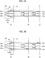
- FIG. 7A is a view illustrating a case in which the optical sensor 5 is shifted from the targeted detection position dp1 to the detection position dp2 toward the center (the rotational center C10) of the optical disc 10 when receiving the influence of oscillation of the casing 2.
- Fig. 7A corresponds to Fig. 4A .
- Fig. 7B is a view illustrating a case in which the optical sensor 5 is shifted from the targeted detection position dp1 to the detection position dp3 toward the outer circumference of the optical disc 10 when receiving the influence of oscillation of the casing 2.
- Fig. 7B corresponds to Fig. 4B .
- Fig. 7A and Fig. 7B illustrate a state in which the rotation reference mark 20i shown in Fig. 3I is formed on the first surface 10a of the optical disc 10.
- the sections (a) to (c) in Fig. 7A and Fig. 7B correspond to the sections (a) to (c) in Fig. 4A and Fig. 4B .
- step S31 in the flowchart shown in Fig. 8 the control circuit 6 controls the traverse mechanism 3 and the optical sensor 5.
- the control circuit 6 controls the traverse mechanism 3 to rotate the optical disc 10 and cause the optical pickup 33 to emit laser light to the optical disc 10.
- the control circuit 6 also controls the optical sensor 5 to emit sensing light to a region in the optical disc 10 in which the rotation reference mark 20 is located.
- step S32 the optical sensor 5 detects the returning light of the sensing light emitted to the optical disc 10 to generate an output signal.
- step S33 the control circuit 6 extracts a detection signal of the rotation reference mark 20i as a pulse waveform from the output signal generated by the optical sensor 5, as shown in Fig. 7A or Fig. 7B .
- the detection signal of the rotation reference mark 20i has a plurality of pulse waveforms corresponding to the respective patterns 20ia to 20ic.
- the control circuit 6 further acquires a pulse interval pt4ab or pt4bc, or a pulse interval pt5ab or pt5bc of the detection signal.
- the control circuit 6 acquires a period (a third period) from a rising point (falling point) t41a or t51a of the pulse waveform corresponding to the pattern 20ia to a rising point (falling point) t41b or t51b of the pulse waveform corresponding to the pattern 20ib, or a period (a fourth period) from the rising point (falling point) t41b or t51b of the pulse waveform corresponding to the pattern 20ib to a rising point (falling point) t41c or t51c of the pulse waveform corresponding to the pattern 20ic.
- the control circuit 6 may acquire both of the third period and the fourth period.
- Example 3 acquires the period (the third and fourth periods) from the rising point (falling point) of the predetermined pulse waveform to the rising point (falling point) of the subsequent pulse waveform. This acquisition process can improve the precision of the acquired period, as compared with the case of acquiring the period from the rising point to the falling point of the predetermined pulse waveform.
- the control circuit 6 can acquire the pulse interval pt4ab or pt5ab based on the third period.
- the control circuit 6 can acquire the pulse interval pt4bc or pt5bc based on the fourth period.
- the control circuit 6 may acquire both the pulse interval pt4ab or pt4bc and the pulse interval pt5ab or pt5bc.
- the pulse intervals pt1ab and pt1bc of the detection signal when the optical sensor 5 is located at the targeted detection position dp1 can be calculated in accordance with the shape of the rotation reference mark 20i and the speed of rotation (rotation rate) of the optical disc 10 (the turntable 31).
- the pulse interval pt1ab can be calculated in accordance with the speed of rotation of the optical disc 10, and a distance (first distance) between the edge of the rotation reference mark 20ia on the side away from the rotation reference mark 20ib and the edge of the rotation reference mark 20ib on the side closer to the rotation reference mark 20ia at the targeted detection position dp1.
- the pulse interval pt1bc can be calculated in accordance with the speed of rotation of the optical disc 10, and a distance (second distance) between the edge of the rotation reference mark 20ib on the side away from the rotation reference mark 20ic and the edge of the rotation reference mark 20ic on the side closer to the rotation reference mark 20ib at the targeted detection position dp1.
- the first and second distances can be preliminarily acquired.
- step S34 the control circuit 6 acquires a speed of rotation at the detection position dp1 in the optical disc 10 based on the speed of rotation of the turntable 31.
- the control circuit 6 acquires the pulse interval pt1ab based on the acquired speed of rotation and the first distance, and acquires the pulse interval pt1bc based on the acquired speed of rotation and the second distance.
- the control circuit 6 may calculate the pulse interval pt1ab based on the acquired speed of rotation and the first distance, and calculate the pulse interval pt1bc based on the acquired speed of rotation and the second distance.
- the control circuit 6 may store a lookup table in which the speed of rotation is associated with the pulse intervals pt1ab and pt1bc of the detection signal at the targeted detection position dp1.
- the control circuit 6 may acquire the pulse interval pt1ab or pt1bc of the detection signal from the lookup table in accordance with the acquired speed of rotation.
- the control circuit 6 may acquire the pulse intervals pt1ab and pt1bc of the detection signal from the lookup table in accordance with the acquired speed of rotation.
- step S35 the control circuit 6 compares the pulse interval pt1ab with the pulse interval pt4ab or pt5ab so as to calculate the shifted amount sa2 or sa3 (first shifted amount) of the actual detection position dp2 or dp3 from the targeted detection position dp1.
- the control circuit 6 compares the pulse interval pt1bc with the pulse interval pt4bc or pt5bc so as to calculate the shifted amount sa2 or sa3 (second shifted amount) of the actual detection position dp2 or dp3 from the targeted detection position dp1.
- the control circuit 6 may calculate the respective shifted amounts sa2 or sa3 (the first and second shifted amounts). The calculation of the plural shifted amounts sa2 or sa3 can improve the precision of the shifted amounts.
- step S36 the control circuit 6 specifies the rotation reference position on the optical disc 10 in accordance with the shifted amount sa2 or sa3 of the actual detection position dp2 or dp3 from the targeted detection position dp1, and the pulse waveform at the detection position dp2 or dp3.
- the optical disc rotation position detection method of Example 3 described above can specify the rotation reference position on the optical disc 10 in accordance with the calculated shifted amount sa2 or sa3 even if the optical sensor 5 is shifted from the targeted detection position dp1 in the radial direction of the optical disc 10 due to the influence of oscillation of the casing 2.
- Example 3 is illustrated with the case of using the rotation reference mark 20i shown in Fig. 3I , the rotation reference mark 20j shown in Fig. 3J may be used instead. Namely, the rotation reference mark 20 used in Example 3 is only required to include the plural patterns arranged at intervals which change in width in the radial direction of the optical disc 10.
- the rotation reference mark 20 used in Example 3 including the plural patterns arranged at intervals is formed such that a reflective film is deposited by masking and patterning, or a reflective member is printed or applied into a predetermined shape.
- the amount of the reflective film or the reflective member to be used can be decreased depending on the intervals arranged, reducing the material cost accordingly.
- the optical disc device 1, the optical disc rotation position detection method, and the optical disc 10 according to the present embodiment enable the formation of the rotation mark 20 having a width changing in the radial direction of the optical disc 10, so as to extract the detection signal of the rotation reference mark 20 from the output signal of the optical sensor 5.
- the optical disc device 1, the optical disc rotation position detection method, and the optical disc 10 according to the present embodiment enable the calculation of the shifted amount of the detection position dp2 or dp3 from the targeted detection position dp 1 based on the detection signal, so as to specify the rotation reference position on the optical disc 10 in accordance with the shifted amount.
- the present embodiment providing the optical disc device 1, the optical disc rotation position detection method, and the optical disc 10 thus can accurately detect the reference position in the rotating direction of the optical disc having no address information even if the casing 2 is oscillated.
- the rotation reference mark 20 is formed on the first surface 10a on the opposite side of the second surface 10b on which the tracks for recording or reading out pieces of information, or the reaction regions are provided.
- the optical disc device 1, the optical disc rotation position detection method, and the optical disc 10 of the present embodiment thus enable the formation of the rotation reference mark having an optional shape at an optional position.
- a notch may be formed having a shape corresponding to any of the rotation reference marks 20a to 20j, for example, at the outer circumference of the optical disc 10.
- the use of the notch having the shape similar to the rotation reference mark 20 can achieve the effects similar to the rotation reference mark 20.
- such a notch could lead the center of gravity of the optical disc 10 to be shifted from the rotational center C10, as compared with the rotation reference mark 20.
- the rotation reference mark 20 is thus preferred so as to avoid the shift of the center of gravity of the optical disc 10 from the rotational center C10 to prevent rotational runout of the optical disc 10.
Landscapes
- Engineering & Computer Science (AREA)
- Theoretical Computer Science (AREA)
- Physics & Mathematics (AREA)
- General Physics & Mathematics (AREA)
- Human Computer Interaction (AREA)
- General Engineering & Computer Science (AREA)
- Computer Security & Cryptography (AREA)
- Life Sciences & Earth Sciences (AREA)
- Health & Medical Sciences (AREA)
- Chemical & Material Sciences (AREA)
- Analytical Chemistry (AREA)
- Biochemistry (AREA)
- General Health & Medical Sciences (AREA)
- Immunology (AREA)
- Pathology (AREA)
- Optical Transform (AREA)
- Optical Measuring Cells (AREA)
- Length Measuring Devices By Optical Means (AREA)
Abstract
Description
- The present disclosure relates to an optical disc device, an optical disc rotation position detection method, and an optical disc.
- Immunoassays are known that quantitatively analyze disease detection and therapeutic effects by detecting particular antigens or antibodies as specimens associated with diseases. Japanese Translation of PCT International Application Publication No.
2002-521666 2006-322819 - The optical disc device scans and detects the nanoparticles captured on the reaction region on the optical disc with laser light emitted from an optical pickup. The optical disc device disclosed in
Patent Documents - The optical disc device moves the optical pickup in a radial direction of the optical disc being rotated. Since the optical disc is provided thereon with a plurality of reaction regions, a reaction region in which nanoparticles are detected needs to be specified. The optical disc device disclosed in
Patent Document 1 specifies a corresponding reaction region by use of address information of the optical disc.Patent Document 2 discloses that the optical disc includes a group of pits in which positional information on reaction regions is recorded. - The optical disc device as disclosed in
Patent Documents - The present disclosure provides an optical disc device, an optical disc rotation position detection method, and an optical disc capable of facilitating a detection of a reference position on the optical disc in a rotating direction regardless of whether address information is recorded in the optical disc.
- A first aspect of one or more embodiments provides an optical disc device including: an optical disc rotation drive unit configured to rotate an optical disc provided with a rotation reference mark; an optical sensor configured to detect the rotation reference mark; and a control circuit configured to control the optical disc rotation drive unit and the optical sensor, the rotation reference mark being formed into a shape having a width changing in a radial direction of the optical disc, the control circuit being configured to extract a detection signal of the rotation reference mark as a pulse waveform from an output signal of the optical sensor with the optical disc being rotated, and specify a rotation reference position of the optical disc in accordance with the pulse waveform.
- A second aspect of one or more embodiments provides an optical disc rotation position detection method including: causing an optical disc rotation drive unit to rotate an optical disc provided with a rotation reference mark formed into a shape having a width changing in a radial direction of the optical disc; causing an optical sensor to detect the rotation reference mark; and causing a control circuit to extract a detection signal of the rotation reference mark as a pulse waveform from an output signal of the optical sensor with the optical disc being rotated, and specify a rotation reference position of the optical disc in accordance with the pulse waveform.
- A third aspect of one or more embodiments provides an optical disc including a rotation reference mark for specifying a rotation reference position of the optical disc, the rotation reference mark being formed into a shape having a width changing in a radial direction of the optical disc.
-
-
Fig. 1 is a configuration diagram showing an optical disc device according to an embodiment as viewed from the side. -
Fig. 2A is a plan view showing an example of an optical disc. -
Fig. 2B is a side view showing the example of the optical disc. -
Fig. 3A is a view showing an example of a rotation reference mark. -
Fig. 3B is a view showing another example of the rotation reference mark. -
Fig. 3C is a view showing still another example of the rotation reference mark. -
Fig. 3D is a view showing still another example of the rotation reference mark. -
Fig. 3E is a view showing still another example of the rotation reference mark. -
Fig. 3F is a view showing still another example of the rotation reference mark. -
Fig. 3G is a view showing still another example of the rotation reference mark. -
Fig. 3H is a view showing still another example of the rotation reference mark. -
Fig. 3I is a view showing still another example of the rotation reference mark. -
Fig. 3J is a view showing still another example of the rotation reference mark. -
Fig. 4A is a view illustrating an optical disc rotation position detection method of Examples 1 and 2. -
Fig. 4B is a view illustrating the optical disc rotation position detection method of Examples 1 and 2. -
Fig. 5 is a flowchart illustrating the optical disc rotation position detection method of Example 1. -
Fig. 6 is a flowchart illustrating the optical disc rotation position detection method of Example 2. -
Fig. 7A is a view illustrating an optical disc rotation position detection method of Example 3. -
Fig. 7B is a view illustrating the optical disc rotation position detection method of Example 3. -
Fig. 8 is a flowchart illustrating the optical disc rotation position detection method of Example 3. - A configuration of an optical disc device according to an embodiment is described below with reference to
Fig. 1 . Theoptical disc device 1 includes acasing 2, atraverse mechanism 3, adamping member 4, anoptical sensor 5, and acontrol circuit 6. Thetraverse mechanism 3 is housed and fixed to thecasing 2 via thedamping member 4. A damper rubber may be used as thedamping member 4. The dampingmember 4 absorbs oscillation of thecasing 2 to avoid further propagation of the oscillation to thetraverse mechanism 3. Theoptical sensor 5 is fixed to thecasing 2. - The
control circuit 6 is electrically connected to thetraverse mechanism 3 and theoptical sensor 5. Thecontrol circuit 6 controls thetraverse mechanism 3 and theoptical sensor 5. An optical disc drive circuit board may be used as thecontrol circuit 6. Thetraverse mechanism 3 includes aturntable 31, arotation drive unit 32, and anoptical pickup 33. A motor may be used as therotation drive unit 32. - The
control circuit 6 controls to cause thetraverse mechanism 3 to move and set anoptical disc 10 onto theturntable 31, or remove theoptical disc 10 set on theturntable 31 from thetraverse mechanism 3. Thetraverse mechanism 3 rotates theturntable 31 at a predetermined rotation rate or at a constant angular velocity, or moves theoptical pickup 33 to a predetermined position in the radial direction of theoptical disc 10. - The
traverse mechanism 3 rotates theturntable 31 to serve as an optical disc rotation drive unit for rotating theoptical disc 10. Thetraverse mechanism 3 can adjust a focal point of laser light emitted to theoptical disc 10 from theoptical pickup 33. - A configuration example of the optical disc according to the embodiment is described below with reference to
Fig. 2A and Fig. 2B . Theoptical disc 10 has afirst surface 10a, asecond surface 10b, and acentral hole 11. The center C11 of thecentral hole 11 conforms to the rotational center C10 of theoptical disc 10. Thefirst surface 10a is provided with arotation reference mark 20. Therotation reference mark 20 is preferably located at or around the circumference of theoptical disc 10. Theoptical sensor 5 is arranged at a position capable of detecting therotation reference mark 20. - The
second surface 10b on the opposite side of thefirst surface 10a is provided with tracks for recording and reading out pieces of information, or provided with reaction regions. As used herein, the "reaction region" refers to a region in which antigens as detection target substances are to be captured and sandwiched between antibodies fixed to theoptical disc 10 and nanoparticles. The detection target substances and the nanoparticles sometimes are not captured in some of the reaction regions. The reaction regions are used for capturing the detection target substances and the nanoparticles. Theoptical pickup 33 is movably positioned within a range capable of recording and reading out pieces of information or within a range capable of detecting the reaction regions in the radial direction of theoptical disc 10. - The
rotation reference mark 20 is described below with reference toFig. 3A to Fig. 3J .Fig. 3A is an enlarged view of therotation reference mark 20 shown inFig. 2A .Fig. 3B to Fig. 3J are views showing other examples of therotation reference mark 20. For making a distinction, the respective rotation reference marks are indicated by thereference numerals 20a to 20j corresponding toFig. 3A to Fig. 3J . - The
rotation reference mark 20a shown inFig. 3A has a triangular shape with a width increasing from the inner circumference to the outer circumference of theoptical disc 10. Therotation reference mark 20b shown inFig. 3B has a sector-like shape with a width increasing from the inner circumference to the outer circumference of theoptical disc 10. Therotation reference mark 20c shown inFig. 3C has a trapezoidal shape with a width increasing from the inner circumference to the outer circumference of theoptical disc 10. The rotation reference mark 20d shown inFig. 3D has a shape with a width increasing from the inner circumference to the outer circumference of theoptical disc 10, having two acute-angled parts and one U-shaped part. - The rotation reference mark 20e shown in
Fig. 3E has a triangular shape with a width decreasing from the inner circumference to the outer circumference of theoptical disc 10. Therotation reference mark 20f shown inFig. 3F has a sector-like shape with a width decreasing from the inner circumference to the outer circumference of theoptical disc 10. Therotation reference mark 20g shown inFig. 3G has a trapezoidal shape with a width decreasing from the inner circumference to the outer circumference of theoptical disc 10. Therotation reference mark 20h shown inFig. 3H has a shape with a width decreasing from the inner circumference to the outer circumference of theoptical disc 10, having two acute-angled parts and one U-shaped part. - The
rotation reference mark 20i shown inFig. 3I includes a plurality of patterns 20ia to 20ic arranged at intervals along the periphery (in the circumferential direction) of theoptical disc 10, the respective intervals changing in width in the radial direction of theoptical disc 10. The respective patterns 20ia to 20ic are formed into a rectangular strip, for example, with the intervals gradually widened from the inner circumference to the outer circumference of theoptical disc 10. Therotation reference mark 20i thus entirely has a shape with a width increasing from the inner circumference to the outer circumference of theoptical disc 10. - The
rotation reference mark 20j shown inFig. 3J includes a plurality of patterns 20ja to 20jc arranged at intervals along the periphery (in the circumferential direction) of theoptical disc 10, the respective intervals changing in width in the radial direction of theoptical disc 10. The respective patterns 20ja to 20jc are formed into a rectangular strip, for example, with the intervals tapering from the inner circumference to the outer circumference of theoptical disc 10. Therotation reference mark 20j thus entirely has a shape with a width decreasing from the inner circumference to the outer circumference of theoptical disc 10. - The respective rotation reference marks 20a to 20j are common in that the width changes in the radial direction of the
optical disc 10. Therotation reference mark 20 thus has a shape with a width changing in the radial direction of theoptical disc 10. The rotation reference mark 20 (20a to 20j) may be either in contact with or separated from the outer circumferential edge of theoptical disc 10. - The rotation reference mark 20 (20a to 20j) may be formed such that a reflective film (such as an aluminum film) is coated on the
first surface 10a of the optical disc 10 (by vapor deposition, for example) and is then subj ected to patterning by photolithography. Alternatively, the rotation reference mark 20 (20a to 20j) may be formed such that a reflective film (such as an aluminum film) is coated on thefirst surface 10a of theoptical disc 10 by masking and patterning (by vapor deposition, for example). - Alternatively, the rotation reference mark 20 (20a to 20j) may be formed such that a reflective member may be printed or applied into a predetermined shape on the
first surface 10a of theoptical disc 10, or a reflective member having a predetermined shape may be bonded to thefirst surface 10a of theoptical disc 10. The reflective film or the reflective member is only required to be made of a material having optical reflectivity. - Detecting the position of the
optical pickup 33 can specify the position on theoptical disc 10 in the radial direction when theoptical disc 10 has no address information. However, a reference position on theoptical disc 10 in the rotating direction still needs to be detected in order to specify the position on theoptical disc 10 in the track direction when having no address information. - As shown in
Fig. 1 , thetraverse mechanism 3 is fixed to thecasing 2 via the dampingmember 4, so as to block off the propagation of oscillation of thecasing 2 to thetraverse mechanism 3. Theoptical pickup 33 and theoptical disc 10 are thus not influenced by the oscillation of thecasing 2. Theoptical sensor 5 and theoptical disc 10 could avoid receiving the influence of oscillation of thecasing 2 even if theoptical sensor 5 could be housed inside thetraverse mechanism 3. However, thetraverse mechanism 3 has substantially no space for housing theoptical sensor 5. Thetraverse mechanism 3 then needs to be redesigned so as to leave a space for housing theoptical sensor 5. Since housing theoptical sensor 5 in thetraverse mechanism 3 is not a practical way, theoptical sensor 5 is thus to be fixed to thecasing 2, as shown inFig. 1 . - The oscillation of the
casing 2 is propagated to theoptical sensor 5 which is fixed to thecasing 2. Theoptical sensor 5, when influenced by the oscillation of thecasing 2, decreases in accuracy of detecting therotation reference mark 20 because of the oscillation. For dealing with this problem, an optical disc rotation position detection method according to the embodiment is illustrated below. - An optical disc rotation position detection method of Example 1 is described with reference to
Fig. 4A, Fig. 4B , and the flowchart shown inFig. 5 .Fig. 4A is a view illustrating a case in which theoptical sensor 5 is shifted from a targeted detection position dp1 to a detection position dp2 toward the center (the rotational center C10) of theoptical disc 10 when receiving the influence of oscillation of thecasing 2.Fig. 4B is a view illustrating a case in which theoptical sensor 5 is shifted from the targeted detection position dp1 to a detection position dp3 toward the outer circumference of theoptical disc 10 when receiving the influence of oscillation of thecasing 2.Fig. 4A and Fig. 4B illustrate a state in which therotation reference mark 20a shown inFig. 3A is formed on thefirst surface 10a of theoptical disc 10. - The section (a) shown in each of
Fig. 4A and Fig. 4B illustrates a partly-enlarged region in theoptical disc 10 in which therotation reference mark 20a is formed. The section (b) shown in each ofFig. 4A and Fig. 4B illustrates an output signal of theoptical sensor 5 corresponding to the targeted detection position dp1. The section (c) shown inFig. 4A illustrates an output signal of theoptical sensor 5 corresponding to the detection position dp2 shifted from the targeted detection position dp1. The section (c) shown inFig. 4B illustrates an output signal of theoptical sensor 5 corresponding to the detection position dp3 shifted from the targeted detection position dp1. - In step S11 in the flowchart shown in
Fig. 5 , thecontrol circuit 6 controls thetraverse mechanism 3 and theoptical sensor 5. In particular, thecontrol circuit 6 controls thetraverse mechanism 3 to rotate theoptical disc 10 and cause theoptical pickup 33 to emit laser light to theoptical disc 10. Thecontrol circuit 6 also controls theoptical sensor 5 to emit sensing light to a region in theoptical disc 10 in which therotation reference mark 20 is located. - In step S12, the
optical sensor 5 detects the returning light of the sensing light emitted to theoptical disc 10 to generate an output signal. In step S13, thecontrol circuit 6 extracts a detection signal of therotation reference mark 20a as a pulse waveform from the output signal generated by theoptical sensor 5, as shown inFig. 4A or Fig. 4B . Thecontrol circuit 6 further acquires a pulse width pw2 or pw3 of the detection signal. - A pulse width pw1 of the detection signal when the
optical sensor 5 is located at the targeted detection position dp1 can be calculated in accordance with the shape of therotation reference mark 20a and a speed of rotation (rotation rate) of the optical disc 10 (the turntable 31). - In step S14, the
control circuit 6 acquires a speed of rotation at the detection position dp1 in theoptical disc 10 based on the speed of rotation of theturntable 31. The width of therotation reference mark 20a at the targeted detection position dp1 can be preliminarily acquired according to the shape of therotation reference mark 20a. The width of therotation reference mark 20a at the targeted detection position dp1 corresponds to a distance between one end and the other end of therotation reference mark 20a in the rotating direction of theoptical disc 10 at the targeted detection position dp1. - The
control circuit 6 acquires the pulse width pw1 of the detection signal in accordance with the acquired speed of rotation and the width of therotation reference mark 20a at the targeted detection position dp1. - The
control circuit 6 may calculate the pulse width pw1 of the detection signal in accordance with the acquired speed of rotation and the width of therotation reference mark 20a at the targeted detection position dp1. Thecontrol circuit 6 may store a lookup table in which the speed of rotation is associated with the pulse width pw1 of the detection signal at the targeted detection position dp1. Thecontrol circuit 6 may acquire the pulse width pw1 of the detection signal from the lookup table in accordance with the acquired speed of rotation. - In step S15, the
control circuit 6 compares the pulse width pw1 with the pulse width pw2 or pw3 so as to calculate the shifted amount sa2 or sa3 of the actual detection position dp2 or dp3 from the targeted detection position dp1. - In particular, the
control circuit 6 calculates a difference between the pulse width pw1 with the pulse width pw2 or pw3, so as to calculate the shifted amount sa2 or sa3 of the detection position dp2 or dp3 from the detection position dp1 in accordance with the calculated difference. - In step S16, the
control circuit 6 specifies the rotation reference position on theoptical disc 10 in accordance with the shifted amount sa2 or sa3 of the detection position dp2 or dp3 from the detection position dp1, a rising point (falling point) t21 or t31 of the pulse waveform, and a falling point (rising point) t22 or t32 of the pulse waveform. - The optical disc rotation position detection method of Example 1 described above can specify the rotation reference position on the
optical disc 10 in accordance with the calculated shifted amount sa2 or sa3 even if theoptical sensor 5 is shifted from the targeted detection position dp1 in the radial direction of theoptical disc 10 due to the influence of oscillation of thecasing 2. - An optical disc rotation position detection method of Example 2 is described with reference to
Fig. 4A, Fig. 4B , and the flowchart shown inFig. 6 . In step S21 in the flowchart shown inFig. 6 , thecontrol circuit 6 controls thetraverse mechanism 3 and theoptical sensor 5. In particular, thecontrol circuit 6 controls thetraverse mechanism 3 to rotate theoptical disc 10 and cause theoptical pickup 33 to emit laser light to theoptical disc 10. Thecontrol circuit 6 also controls theoptical sensor 5 to emit sensing light to a region in theoptical disc 10 in which therotation reference mark 20 is located. - In step S22, the
optical sensor 5 detects the returning light of the sensing light emitted to theoptical disc 10 to generate an output signal. In step S23, thecontrol circuit 6 extracts a detection signal of therotation reference mark 20a as a pulse waveform from the output signal generated by theoptical sensor 5, as shown inFig. 4A or Fig. 4B . Thecontrol circuit 6 further acquires a pulse width pw2 or pw3 of the detection signal. - In particular, the
control circuit 6 acquires a first period from the rising point (falling point) t21 or t31 of the pulse waveform to the falling point (rising point) t22 or t32 (corresponding to the pulse width pw2 or pw3), and a second period from the point t21 or t31 to the subsequent rising point (falling point) t21 or t31 of the pulse waveform detected next (a period during one rotation of the optical disc 10). Thecontrol circuit 6 calculates a ratio of the first period to the second period, so as to obtain a ratio of the pulse width pw2 or pw3. Namely, the ratio of the pulse width pw2 or pw3 is a ratio of the pulse width pw2 or pw3 to the period during one rotation of theoptical disc 10. - A ratio of the pulse width pw1 of the detection signal when the
optical sensor 5 is located at the targeted detection position dp1 can be calculated in accordance with the shape of therotation reference mark 20a and the speed of rotation (rotation rate) of the optical disc 10 (the turntable 31). - In step S24, the
control circuit 6 acquires a speed of rotation at the detection position dp1 in theoptical disc 10 based on the speed of rotation of theturntable 31. The width of therotation reference mark 20a at the targeted detection position dp1 can be preliminarily acquired according to the shape of therotation reference mark 20a. The width of therotation reference mark 20a at the targeted detection position dp1 corresponds to a distance between one end and the other end of therotation reference mark 20a in the rotating direction of theoptical disc 10 at the targeted detection position dp1. - A length for one rotation of the
optical disc 10 at the targeted detection position dp1 can be preliminarily acquired. The ratio of the pulse width pw1 thus can be calculated by dividing the width of therotation reference mark 20a at the targeted detection position dp1 by the length for one rotation of theoptical disc 10. - The
control circuit 6 acquires the ratio of the pulse width pw1 of the detection signal in accordance with the acquired speed of rotation, the width of therotation reference mark 20a at the targeted detection position dp1, and the length for one rotation of theoptical disc 10 at the targeted detection position dp1. The ratio of the pulse width pw1 is a ratio of the pulse width pw1 to the period during one rotation of theoptical disc 10. - The
control circuit 6 may calculate the ratio of the pulse width pw1 of the detection signal in accordance with the acquired speed of rotation and the width of therotation reference mark 20a at the targeted detection position dp1. Thecontrol circuit 6 may store a lookup table in which the speed of rotation is associated with the ratio of the pulse width pw1 of the detection signal at the targeted detection position dp1. Thecontrol circuit 6 may acquire the ratio of the pulse width pw1 of the detection signal from the lookup table in accordance with the acquired speed of rotation. - In step S25, the
control circuit 6 calculates the shifted amount sa2 or sa3 of the actual detection position dp2 or dp3 from the targeted detection position dp1 in accordance with the ratio of the pulse width pw1 and the ratio of the pulse width pw2 or pw3. - In step S26, the
control circuit 6 specifies the rotation reference position on theoptical disc 10 in accordance with the shifted amount sa2 or sa3 of the detection position dp2 or dp3 from the detection position dp1, the rising point (falling point) t21 or t31 of the pulse waveform, and the falling point (rising point) t22 or t32 of the pulse waveform. - The optical disc rotation position detection method of Example 2 described above can specify the rotation reference position on the
optical disc 10 in accordance with the calculated shifted amount sa2 or sa3 even if theoptical sensor 5 is shifted from the targeted detection position dp1 in the radial direction of theoptical disc 10 due to the influence of oscillation of thecasing 2. - An optical disc rotation position detection method of Example 3 is described with reference to
Fig. 7A, Fig. 7B , and the flowchart shown inFig. 8 .Fig. 7A is a view illustrating a case in which theoptical sensor 5 is shifted from the targeted detection position dp1 to the detection position dp2 toward the center (the rotational center C10) of theoptical disc 10 when receiving the influence of oscillation of thecasing 2.Fig. 7A corresponds toFig. 4A . -
Fig. 7B is a view illustrating a case in which theoptical sensor 5 is shifted from the targeted detection position dp1 to the detection position dp3 toward the outer circumference of theoptical disc 10 when receiving the influence of oscillation of thecasing 2.Fig. 7B corresponds toFig. 4B .Fig. 7A and Fig. 7B illustrate a state in which therotation reference mark 20i shown inFig. 3I is formed on thefirst surface 10a of theoptical disc 10. The sections (a) to (c) inFig. 7A and Fig. 7B correspond to the sections (a) to (c) inFig. 4A and Fig. 4B . - In step S31 in the flowchart shown in
Fig. 8 , thecontrol circuit 6 controls thetraverse mechanism 3 and theoptical sensor 5. In particular, thecontrol circuit 6 controls thetraverse mechanism 3 to rotate theoptical disc 10 and cause theoptical pickup 33 to emit laser light to theoptical disc 10. Thecontrol circuit 6 also controls theoptical sensor 5 to emit sensing light to a region in theoptical disc 10 in which therotation reference mark 20 is located. - In step S32, the
optical sensor 5 detects the returning light of the sensing light emitted to theoptical disc 10 to generate an output signal. In step S33, thecontrol circuit 6 extracts a detection signal of therotation reference mark 20i as a pulse waveform from the output signal generated by theoptical sensor 5, as shown inFig. 7A or Fig. 7B . The detection signal of therotation reference mark 20i has a plurality of pulse waveforms corresponding to the respective patterns 20ia to 20ic. Thecontrol circuit 6 further acquires a pulse interval pt4ab or pt4bc, or a pulse interval pt5ab or pt5bc of the detection signal. - With regard to the
rotation reference mark 20i, for example, thecontrol circuit 6 acquires a period (a third period) from a rising point (falling point) t41a or t51a of the pulse waveform corresponding to the pattern 20ia to a rising point (falling point) t41b or t51b of the pulse waveform corresponding to the pattern 20ib, or a period (a fourth period) from the rising point (falling point) t41b or t51b of the pulse waveform corresponding to the pattern 20ib to a rising point (falling point) t41c or t51c of the pulse waveform corresponding to the pattern 20ic. Thecontrol circuit 6 may acquire both of the third period and the fourth period. - While
Fig. 7A and Fig. 7B illustrate the rectangular pulse waveforms, the rising point and the falling point of the respective waveforms are actually not sharpened. Example 3 acquires the period (the third and fourth periods) from the rising point (falling point) of the predetermined pulse waveform to the rising point (falling point) of the subsequent pulse waveform. This acquisition process can improve the precision of the acquired period, as compared with the case of acquiring the period from the rising point to the falling point of the predetermined pulse waveform. - The
control circuit 6 can acquire the pulse interval pt4ab or pt5ab based on the third period. Thecontrol circuit 6 can acquire the pulse interval pt4bc or pt5bc based on the fourth period. Thecontrol circuit 6 may acquire both the pulse interval pt4ab or pt4bc and the pulse interval pt5ab or pt5bc. - The pulse intervals pt1ab and pt1bc of the detection signal when the
optical sensor 5 is located at the targeted detection position dp1 can be calculated in accordance with the shape of therotation reference mark 20i and the speed of rotation (rotation rate) of the optical disc 10 (the turntable 31). In particular, the pulse interval pt1ab can be calculated in accordance with the speed of rotation of theoptical disc 10, and a distance (first distance) between the edge of the rotation reference mark 20ia on the side away from the rotation reference mark 20ib and the edge of the rotation reference mark 20ib on the side closer to the rotation reference mark 20ia at the targeted detection position dp1. The pulse interval pt1bc can be calculated in accordance with the speed of rotation of theoptical disc 10, and a distance (second distance) between the edge of the rotation reference mark 20ib on the side away from the rotation reference mark 20ic and the edge of the rotation reference mark 20ic on the side closer to the rotation reference mark 20ib at the targeted detection position dp1. The first and second distances can be preliminarily acquired. - In step S34, the
control circuit 6 acquires a speed of rotation at the detection position dp1 in theoptical disc 10 based on the speed of rotation of theturntable 31. Thecontrol circuit 6 acquires the pulse interval pt1ab based on the acquired speed of rotation and the first distance, and acquires the pulse interval pt1bc based on the acquired speed of rotation and the second distance. - The
control circuit 6 may calculate the pulse interval pt1ab based on the acquired speed of rotation and the first distance, and calculate the pulse interval pt1bc based on the acquired speed of rotation and the second distance. Thecontrol circuit 6 may store a lookup table in which the speed of rotation is associated with the pulse intervals pt1ab and pt1bc of the detection signal at the targeted detection position dp1. Thecontrol circuit 6 may acquire the pulse interval pt1ab or pt1bc of the detection signal from the lookup table in accordance with the acquired speed of rotation. Thecontrol circuit 6 may acquire the pulse intervals pt1ab and pt1bc of the detection signal from the lookup table in accordance with the acquired speed of rotation. - In step S35, the
control circuit 6 compares the pulse interval pt1ab with the pulse interval pt4ab or pt5ab so as to calculate the shifted amount sa2 or sa3 (first shifted amount) of the actual detection position dp2 or dp3 from the targeted detection position dp1. Thecontrol circuit 6 compares the pulse interval pt1bc with the pulse interval pt4bc or pt5bc so as to calculate the shifted amount sa2 or sa3 (second shifted amount) of the actual detection position dp2 or dp3 from the targeted detection position dp1. - The
control circuit 6 may calculate the respective shifted amounts sa2 or sa3 (the first and second shifted amounts). The calculation of the plural shifted amounts sa2 or sa3 can improve the precision of the shifted amounts. - In step S36, the
control circuit 6 specifies the rotation reference position on theoptical disc 10 in accordance with the shifted amount sa2 or sa3 of the actual detection position dp2 or dp3 from the targeted detection position dp1, and the pulse waveform at the detection position dp2 or dp3. - The optical disc rotation position detection method of Example 3 described above can specify the rotation reference position on the
optical disc 10 in accordance with the calculated shifted amount sa2 or sa3 even if theoptical sensor 5 is shifted from the targeted detection position dp1 in the radial direction of theoptical disc 10 due to the influence of oscillation of thecasing 2. - While Example 3 is illustrated with the case of using the
rotation reference mark 20i shown inFig. 3I , therotation reference mark 20j shown inFig. 3J may be used instead. Namely, therotation reference mark 20 used in Example 3 is only required to include the plural patterns arranged at intervals which change in width in the radial direction of theoptical disc 10. - The
rotation reference mark 20 used in Example 3 including the plural patterns arranged at intervals is formed such that a reflective film is deposited by masking and patterning, or a reflective member is printed or applied into a predetermined shape. The amount of the reflective film or the reflective member to be used can be decreased depending on the intervals arranged, reducing the material cost accordingly. - The
optical disc device 1, the optical disc rotation position detection method, and theoptical disc 10 according to the present embodiment enable the formation of therotation mark 20 having a width changing in the radial direction of theoptical disc 10, so as to extract the detection signal of therotation reference mark 20 from the output signal of theoptical sensor 5. Theoptical disc device 1, the optical disc rotation position detection method, and theoptical disc 10 according to the present embodiment enable the calculation of the shifted amount of the detection position dp2 or dp3 from the targeteddetection position dp 1 based on the detection signal, so as to specify the rotation reference position on theoptical disc 10 in accordance with the shifted amount. - The present embodiment providing the
optical disc device 1, the optical disc rotation position detection method, and theoptical disc 10 thus can accurately detect the reference position in the rotating direction of the optical disc having no address information even if thecasing 2 is oscillated. - According to the
optical disc device 1, the optical disc rotation position detection method, and theoptical disc 10 of the present embodiment, therotation reference mark 20 is formed on thefirst surface 10a on the opposite side of thesecond surface 10b on which the tracks for recording or reading out pieces of information, or the reaction regions are provided. Theoptical disc device 1, the optical disc rotation position detection method, and theoptical disc 10 of the present embodiment thus enable the formation of the rotation reference mark having an optional shape at an optional position. - It should be understood that the present invention is not intended to be limited to the embodiment described above, and various modifications will be apparent to those skilled in the art without departing from the scope of the present invention.
- Instead of the rotation reference mark, a notch may be formed having a shape corresponding to any of the rotation reference marks 20a to 20j, for example, at the outer circumference of the
optical disc 10. The use of the notch having the shape similar to therotation reference mark 20 can achieve the effects similar to therotation reference mark 20. However, such a notch could lead the center of gravity of theoptical disc 10 to be shifted from the rotational center C10, as compared with therotation reference mark 20. Therotation reference mark 20 is thus preferred so as to avoid the shift of the center of gravity of theoptical disc 10 from the rotational center C10 to prevent rotational runout of theoptical disc 10.
Claims (6)
- An optical disc device comprising:an optical disc rotation drive unit configured to rotate an optical disc provided with a rotation reference mark over the optical disc;an optical sensor configured to detect the rotation reference mark; anda control circuit configured to control the optical disc rotation drive unit and the optical sensor,the rotation reference mark being formed into a shape having a width changing in a radial direction of the optical disc,the control circuit being configured to extract a detection signal of the rotation reference mark as a pulse waveform from an output signal of the optical sensor with the optical disc being rotated, and specify a rotation reference position of the optical disc in accordance with the pulse waveform.
- The optical disc device according to claim 1, wherein the control circuit configured to calculate a shifted amount of an actual detection position from a targeted detection position in accordance with the pulse waveform, and specifies the rotation reference position of the optical disc in accordance with the shifted amount.
- An optical disc rotation position detection method comprising:causing an optical disc rotation drive unit to rotate an optical disc provided with a rotation reference mark formed into a shape having a width changing in a radial direction of the optical disc;causing an optical sensor to detect the rotation reference mark; andcausing a control circuit to extract a detection signal of the rotation reference mark as a pulse waveform from an output signal of the optical sensor with the optical disc being rotated, and specify a rotation reference position of the optical disc in accordance with the pulse waveform.
- An optical disc comprising a rotation reference mark for specifying a rotation reference position of the optical disc, the rotation reference mark being formed into a shape having a width changing in a radial direction of the optical disc.
- The optical disc according to claim 4, wherein the rotation reference mark includes a plurality of patterns arranged at intervals in a circumferential direction of the optical disc, the intervals changing in width in the radial direction of the optical disc.
- The optical disc according to claim 4 or 5, further comprising:a first surface provided with the rotation reference mark; anda second surface on another side of the first surface and provided with a track or a reaction region for capturing nanoparticles.
Applications Claiming Priority (1)
| Application Number | Priority Date | Filing Date | Title |
|---|---|---|---|
| JP2018222294A JP7127512B2 (en) | 2018-11-28 | 2018-11-28 | Optical disc device and optical disc rotation position detection method |
Publications (1)
| Publication Number | Publication Date |
|---|---|
| EP3660515A1 true EP3660515A1 (en) | 2020-06-03 |
Family
ID=68655433
Family Applications (1)
| Application Number | Title | Priority Date | Filing Date |
|---|---|---|---|
| EP19211309.0A Withdrawn EP3660515A1 (en) | 2018-11-28 | 2019-11-25 | Optical disc device, optical disc rotation position detection method, and optical disc |
Country Status (5)
| Country | Link |
|---|---|
| US (1) | US11003371B2 (en) |
| EP (1) | EP3660515A1 (en) |
| JP (1) | JP7127512B2 (en) |
| KR (1) | KR102265222B1 (en) |
| CN (1) | CN111243630B (en) |
Citations (9)
| Publication number | Priority date | Publication date | Assignee | Title |
|---|---|---|---|---|
| JPS58169354A (en) * | 1982-03-31 | 1983-10-05 | Hitachi Ltd | information recording disk |
| JP2002521666A (en) | 1998-07-21 | 2002-07-16 | バースタイン テクノロジーズ,インコーポレイティド | Optical disc based assay device and method |
| JP2006322819A (en) | 2005-05-19 | 2006-11-30 | Sony Corp | Substrate and apparatus for bioassay, and method for producing substrate |
| US20070047403A1 (en) * | 2005-08-29 | 2007-03-01 | Hanks D M | Method of laser spot location and adjustment thereof |
| US20150318011A1 (en) * | 2012-11-30 | 2015-11-05 | Hitachi Consumer Electronics Co., Ltd. | Recording/reproducing apparatus and recording medium |
| US9953806B1 (en) * | 2015-03-26 | 2018-04-24 | Doug Carson & Associates, Inc. | Substrate alignment detection using circumferentially extending timing pattern |
| US20180217175A1 (en) * | 2015-09-30 | 2018-08-02 | JVC Kenwood Corporation | Analysis device and analysis method |
| US20180321227A1 (en) * | 2016-02-03 | 2018-11-08 | JVC Kenwood Corporation | Analysis Device and Analysis Method |
| EP3483587A1 (en) * | 2017-11-10 | 2019-05-15 | JVC KENWOOD Corporation | Analysis device and analysis method |
Family Cites Families (14)
| Publication number | Priority date | Publication date | Assignee | Title |
|---|---|---|---|---|
| JP2810035B2 (en) * | 1986-08-22 | 1998-10-15 | 株式会社日立製作所 | Optical recording / reproducing method |
| JPH06103612A (en) * | 1992-09-22 | 1994-04-15 | Sony Corp | Information recording disk and disk drive |
| JP3198490B2 (en) * | 1993-03-02 | 2001-08-13 | ソニー株式会社 | Eccentricity measuring device |
| US6970400B1 (en) * | 1999-09-27 | 2005-11-29 | Hitachi Maxell, Ltd. | Information recording medium with magnetic marks, recording and reproducing apparatus therefor, and head positioning method using detected magnetic leakage fields from the magnetic marks |
| US20040141445A1 (en) | 2003-01-17 | 2004-07-22 | Hanks Darwin Mitchel | Radial position registration for a trackless optical disc surface |
| US7219840B2 (en) | 2003-01-17 | 2007-05-22 | Hewlett-Packard Development Company, L.P. | Calibrating fine actuator using a reference pattern |
| JP2007141417A (en) * | 2005-11-22 | 2007-06-07 | Sony Corp | Write-once optical recording medium and manufacturing method thereof |
| JP2008299912A (en) * | 2007-05-29 | 2008-12-11 | Hitachi Global Storage Technologies Netherlands Bv | Hard disk media with alignment pattern and alignment method |
| JP2012069215A (en) * | 2010-09-24 | 2012-04-05 | Hitachi-Lg Data Storage Inc | Optical disk drive, information recording method and optical disk |
| US9466324B2 (en) * | 2013-10-31 | 2016-10-11 | Seagate Technology Llc | Bit patterned media template including alignment mark and method of using same |
| JP6087272B2 (en) | 2013-12-20 | 2017-03-01 | 信越ポリマー株式会社 | Analysis board |
| EP3144681B1 (en) | 2014-05-15 | 2019-04-17 | Takano Co., Ltd. | Sample analyzing apparatus |
| US9627179B2 (en) | 2015-03-26 | 2017-04-18 | Doug Carson & Associates, Inc. | Substrate alignment through detection of rotating timing pattern |
| JP6958166B2 (en) * | 2017-02-22 | 2021-11-02 | 株式会社Jvcケンウッド | Analytical equipment and analytical method |
-
2018
- 2018-11-28 JP JP2018222294A patent/JP7127512B2/en active Active
-
2019
- 2019-11-11 KR KR1020190143539A patent/KR102265222B1/en not_active Expired - Fee Related
- 2019-11-21 CN CN201911146938.3A patent/CN111243630B/en not_active Expired - Fee Related
- 2019-11-25 EP EP19211309.0A patent/EP3660515A1/en not_active Withdrawn
- 2019-11-26 US US16/695,800 patent/US11003371B2/en not_active Expired - Fee Related
Patent Citations (9)
| Publication number | Priority date | Publication date | Assignee | Title |
|---|---|---|---|---|
| JPS58169354A (en) * | 1982-03-31 | 1983-10-05 | Hitachi Ltd | information recording disk |
| JP2002521666A (en) | 1998-07-21 | 2002-07-16 | バースタイン テクノロジーズ,インコーポレイティド | Optical disc based assay device and method |
| JP2006322819A (en) | 2005-05-19 | 2006-11-30 | Sony Corp | Substrate and apparatus for bioassay, and method for producing substrate |
| US20070047403A1 (en) * | 2005-08-29 | 2007-03-01 | Hanks D M | Method of laser spot location and adjustment thereof |
| US20150318011A1 (en) * | 2012-11-30 | 2015-11-05 | Hitachi Consumer Electronics Co., Ltd. | Recording/reproducing apparatus and recording medium |
| US9953806B1 (en) * | 2015-03-26 | 2018-04-24 | Doug Carson & Associates, Inc. | Substrate alignment detection using circumferentially extending timing pattern |
| US20180217175A1 (en) * | 2015-09-30 | 2018-08-02 | JVC Kenwood Corporation | Analysis device and analysis method |
| US20180321227A1 (en) * | 2016-02-03 | 2018-11-08 | JVC Kenwood Corporation | Analysis Device and Analysis Method |
| EP3483587A1 (en) * | 2017-11-10 | 2019-05-15 | JVC KENWOOD Corporation | Analysis device and analysis method |
Also Published As
| Publication number | Publication date |
|---|---|
| US11003371B2 (en) | 2021-05-11 |
| US20200167090A1 (en) | 2020-05-28 |
| KR102265222B1 (en) | 2021-06-14 |
| KR20200063975A (en) | 2020-06-05 |
| JP2020085719A (en) | 2020-06-04 |
| CN111243630B (en) | 2021-09-21 |
| JP7127512B2 (en) | 2022-08-30 |
| CN111243630A (en) | 2020-06-05 |
Similar Documents
| Publication | Publication Date | Title |
|---|---|---|
| EP1059630A4 (en) | METHOD AND DEVICE FOR SEARCHING CONDITIONS ON AN OPTICAL DISC RECORDING PULSE | |
| US6904010B1 (en) | Method of writing servo tracks for disk file apparatus using write start or stop sectors | |
| US7623420B2 (en) | Focus servo control method in optical disc device | |
| US11003371B2 (en) | Optical disc device, optical disc rotation position detection method, and optical disc having rotation reference mark formed as width changing in radial direction | |
| KR950002395B1 (en) | Method of accessing control track by positioning optical head at center of control track | |
| EP1376550A2 (en) | Tilt correction device | |
| EP1705648A2 (en) | Focus servo control method in optical disc device | |
| JPS6132732B2 (en) | ||
| JPH07174771A (en) | Optical angular-velocity measuring instrument and tape scanning device | |
| US6462323B1 (en) | Tilt detector and tilt detection method in the radial and tangential directions | |
| JP2020118537A (en) | Optical disk device, and method for detecting optical disk rotation position | |
| WO2006077619A1 (en) | Information reproduction device and method for measuring surface runout | |
| US20100177608A1 (en) | Optical disc and method for controlling the same | |
| JPH04205719A (en) | optical memory device | |
| JPH09106618A (en) | Disk unit | |
| JP2000215485A (en) | Optical disk drive | |
| JP2867304B2 (en) | Optical disk drive | |
| KR20050032576A (en) | Disc drive apparatus | |
| JPH04238120A (en) | Focus position control device | |
| JPH08273182A (en) | Rotary recorder | |
| JPH09270143A (en) | Optical disk device | |
| KR910001689A (en) | High speed positioning drive of optical pickup head | |
| JP2008077715A (en) | Optical disk device | |
| JPH0652503A (en) | Magneto-optical disk device | |
| JPH02165426A (en) | optical recording and reproducing device |
Legal Events
| Date | Code | Title | Description |
|---|---|---|---|
| PUAI | Public reference made under article 153(3) epc to a published international application that has entered the european phase |
Free format text: ORIGINAL CODE: 0009012 |
|
| STAA | Information on the status of an ep patent application or granted ep patent |
Free format text: STATUS: REQUEST FOR EXAMINATION WAS MADE |
|
| 17P | Request for examination filed |
Effective date: 20191125 |
|
| AK | Designated contracting states |
Kind code of ref document: A1 Designated state(s): AL AT BE BG CH CY CZ DE DK EE ES FI FR GB GR HR HU IE IS IT LI LT LU LV MC MK MT NL NO PL PT RO RS SE SI SK SM TR |
|
| AX | Request for extension of the european patent |
Extension state: BA ME |
|
| RBV | Designated contracting states (corrected) |
Designated state(s): AL AT BE BG CH CY CZ DE DK EE ES FI FR GB GR HR HU IE IS IT LI LT LU LV MC MK MT NL NO PL PT RO RS SE SI SK SM TR |
|
| STAA | Information on the status of an ep patent application or granted ep patent |
Free format text: STATUS: EXAMINATION IS IN PROGRESS |
|
| 17Q | First examination report despatched |
Effective date: 20220513 |
|
| STAA | Information on the status of an ep patent application or granted ep patent |
Free format text: STATUS: THE APPLICATION HAS BEEN WITHDRAWN |
|
| 18W | Application withdrawn |
Effective date: 20231103 |