EP3660445A1 - Klemmvorrichtung - Google Patents
Klemmvorrichtung Download PDFInfo
- Publication number
- EP3660445A1 EP3660445A1 EP19200139.4A EP19200139A EP3660445A1 EP 3660445 A1 EP3660445 A1 EP 3660445A1 EP 19200139 A EP19200139 A EP 19200139A EP 3660445 A1 EP3660445 A1 EP 3660445A1
- Authority
- EP
- European Patent Office
- Prior art keywords
- connecting element
- clamping device
- clamping
- clamping sleeve
- probe
- Prior art date
- Legal status (The legal status is an assumption and is not a legal conclusion. Google has not performed a legal analysis and makes no representation as to the accuracy of the status listed.)
- Granted
Links
Images




Classifications
-
- G—PHYSICS
- G01—MEASURING; TESTING
- G01B—MEASURING LENGTH, THICKNESS OR SIMILAR LINEAR DIMENSIONS; MEASURING ANGLES; MEASURING AREAS; MEASURING IRREGULARITIES OF SURFACES OR CONTOURS
- G01B5/00—Measuring arrangements characterised by the use of mechanical techniques
- G01B5/0002—Arrangements for supporting, fixing or guiding the measuring instrument or the object to be measured
- G01B5/0004—Supports
-
- G—PHYSICS
- G01—MEASURING; TESTING
- G01B—MEASURING LENGTH, THICKNESS OR SIMILAR LINEAR DIMENSIONS; MEASURING ANGLES; MEASURING AREAS; MEASURING IRREGULARITIES OF SURFACES OR CONTOURS
- G01B5/00—Measuring arrangements characterised by the use of mechanical techniques
- G01B5/0011—Arrangements for eliminating or compensation of measuring errors due to temperature or weight
- G01B5/0014—Arrangements for eliminating or compensation of measuring errors due to temperature or weight due to temperature
Definitions
- the present invention relates to a clamping device for fastening a probe, in particular a length probe, to a carrier.
- a generic clamping device is out DE 10 2016 219 714 A1 known.
- the clamping device consists of a clamping sleeve for gripping the probe shaft of a length measuring probe.
- the clamping sleeve has an arrangement of a plurality of bending beams which are distributed over the circumference and run axially and which can be moved with the aid of a clamping device against the stylus shaft.
- the clamping device consists of an arrangement of shells distributed over the circumference of the clamping sleeve and its diameter adjustable by means of a screw in such a way that this exerts an inward radial force on the clamping sleeve and thereby moves the bending beam against the feeler shaft.
- a disadvantage of known clamping devices is that the clamping force is not constant as a function of the temperature. Rather, it is subject to temperature fluctuations. This leads to the fact that the clamping of the stylus shaft is no longer sufficiently secure after a certain time. As a result of the temperature fluctuations, the clamping force can in particular decrease or even be lost.
- the present invention has for its object to provide a clamping device with which a safe clamping or clamping of the shaft of a probe is made possible regardless of temperature fluctuations.
- the clamping device designed according to the invention comprises a clamping sleeve for gripping around a shaft of the measuring probe, the clamping sleeve being elastically deformable in such a way that it can be pressed against the shaft of the measuring probe.
- the clamping device further comprises a first connecting element which surrounds the clamping sleeve in such a way that a hollow cylindrical space is formed between the clamping sleeve and the first connecting element at least along a longitudinal section of the clamping device.
- the clamping device further comprises a second connecting element, the first connecting element and the second connecting element being rotatably fastened to one another.
- the clamping device further comprises a sliding ring element which is arranged between the clamping sleeve and the first connecting element on the one hand and between the hollow cylindrical space and a pressurizing part of the clamping device on the other hand.
- the clamping device further comprises a compression element, which is introduced into the hollow cylindrical space.
- the clamping device is designed such that when the two connecting elements are rotated relative to one another, the pressurizing part exerts an axial force directed in the direction of the compression element on the slide ring element and thereby moves the slide ring element against the compression element, as a result of which the axial force is transmitted to the compression element.
- the compression element is designed such that upon experiencing the axial force it exerts a radial force directed in the direction of the shaft of the probe on the clamping sleeve and thereby presses the clamping sleeve against the shaft of the probe.
- the compression element has a coefficient of thermal expansion which is adapted to the coefficient of thermal expansion of the clamping sleeve and the first connecting element such that a change in the radial force caused by a change in temperature is avoided or at least reduced.
- the radial force can also be referred to as clamping force or clamping force.
- the clamping force or clamping force can be kept or kept essentially constant even when the temperature changes. This ensures that the shaft of the probe is clamped or clamped independently of temperature fluctuations.
- the compression element has a thermal coefficient of linear expansion in the range from 8 to 25 x 10 -6 K -1 , preferably about 8.5 x 10 -6 K -1 , and if the clamping sleeve, the first connecting element, the second connecting element and / or the slide ring element has a thermal coefficient of linear expansion in the range from 8 to 25 x 10 -6 K -1 , preferably about 10 x 10 -6 K -1 .
- the compression element has a thermal coefficient of linear expansion in the range from 9 to 12 x 10 -6 K -1 and if the clamping sleeve that first connecting element, the second connecting element and / or the sliding ring element have a thermal coefficient of linear expansion in the range from 9 to 12 x 10 -6 K -1 .
- both the compression element and the clamping sleeve, the first connecting element, the second connecting element and / or the sliding ring element can have a coefficient of thermal expansion of approximately zero.
- the compression element has a comparable or similar thermal coefficient of linear expansion as the other components of the clamping device, in particular the clamping sleeve, the first connecting element, the second connecting element and / or the slide ring element.
- the compression element preferably comprises glass fiber roving or alternatively carbon fiber roving, glass powder, glass balls, steel wire, steel powder, steel balls or a plastic with a certain glass fiber content, while the clamping sleeve, the first connecting element, the second connecting element and / or the sliding ring element preferably consists of Steel or alternatively made of brass, aluminum or Invar.
- a measuring arrangement with a measuring probe, in particular a length measuring probe, a carrier and a clamping device designed according to the invention is specified in claim 15.
- the invention is based on the Figures 1 to 6 using the example of a measuring arrangement 10, which includes a length measuring probe 12 with a shaft 14 and a stylus 16 guided therein in the longitudinal direction X.
- the length measuring probe 12 is fastened to a stationary support 18 in that the shaft 14 of the length measuring probe 12 is clamped circumferentially by a clamping device 20 according to the invention.
- the clamping device 20 is designed to hold the shaft 14 of the length measuring probe 12 stationary on the carrier 18 on the one hand and to exert a clamping force or clamping force which is essentially constant depending on the temperature on the shaft 14 of the length measuring probe 12 on the other hand.
- the clamping device 20 is based on the Figures 3 to 5 explained in more detail.
- the clamping device 20 comprises a clamping sleeve 22, a first connecting element 24, a second connecting element 26, a slide ring element 34 and a compression element 38.
- the clamping sleeve 22 serves to grip around the shaft 14 of the length measuring probe 12.
- the clamping sleeve 22 is elastically deformable in such a way that it can be pressed against the shaft 14 of the length measuring probe 12.
- the first connecting element 24 surrounds the clamping sleeve 22 in such a way that a hollow cylindrical space 28 is formed between the clamping sleeve 22 and the first connecting element 24 at least along a longitudinal section of the clamping device 20.
- the second link 26 is rotatably attached to one end of the first link 24.
- the slide ring element 34 is arranged on an end of the clamping sleeve 22 facing the second connecting element 26 between the clamping sleeve 22 and the first connecting element 24 on the one hand and between the hollow cylindrical intermediate space 28 and a pressurizing part 36 of the clamping device 20 on the other hand.
- the pressurizing part 36 is a hollow cylindrical section of the second connecting element 26, which adjoins the slide ring element 34 on a side opposite the hollow cylindrical intermediate space 28.
- the compression element 38 is introduced into the hollow cylindrical space 28.
- the first connecting element 24 is an essentially hollow cylindrical housing part.
- the second connecting element 26 is a nut that can be screwed to the first connecting element 24.
- the first connecting element 24 has a first external thread 30.1 which is provided on the end of the first connecting element 24 facing the second connecting element 26 and which engages with an internal thread 32 of the second connecting element 26.
- the first connecting element 24 can be screwed to an upper edge portion of the clamping sleeve 22 at an end of the first connecting element 24 facing away from the second connecting element 26.
- the clamping sleeve 22 can also be inserted into the first connecting element 24 without screwing.
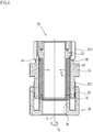
- the mounting state of the clamping device 20 is particularly in Figure 4 shown.
- the clamping device 20 is designed such that when the second connecting element 26 is rotated relative to the first connecting element 24, the pressurizing part 36 exerts an axial force directed in the direction of the compression element 38 on the slide ring element 34 and thereby moves the slide ring element 34 against the compression element 38, as a result of which the axial force is transmitted to the compression element 38.
- the compression element 38 is designed such that upon experiencing the axial force it exerts a radial force F R directed in the direction of the shaft 14 of the length measuring probe 12 on the clamping sleeve 22 and thereby presses the clamping sleeve 22 against the shaft 14 of the length measuring probe 12.
- the compression element 38 has a thermal expansion coefficient which is adapted to the thermal expansion coefficients of the clamping sleeve 22 and the first connecting element 24 such that a change in the radial force F R caused by a change in temperature is avoided or at least reduced. It is thereby achieved that the clamping device 20 is insensitive to temperature fluctuations.
- the compression element 38 has a material 40 comprising fibers, preferably glass fibers.
- the compression element 38 thus preferably has the thermal coefficient of linear expansion 8.5 x 10 -6 K -1 .
- the clamping sleeve 22 and the first connecting element 24 are preferably made of steel with the thermal expansion coefficient 10 x 10 -6 K -1 .
- the second connecting element 26 and the sliding ring element 34 can also be made of steel with the same thermal coefficient of linear expansion.
- the compression element 38 has a thermal expansion coefficient that is comparable or similar to that of at least the clamping sleeve 22 and the first connecting element 24. This is advantageous over the use of a hydraulic fluid, such as hydraulic oil, as a compression element, since the hydraulic fluid is typically a lot compared to steel has larger coefficients of thermal expansion. In this case the insensitivity to temperature fluctuations of the clamping device 20 no longer exists.
- the compression element 38 is a winding body made of glass fiber roving.
- the compression element 38 can be designed to be compressible to a certain degree, as a result of which the radial force F R is brought about when pressure is applied in the axial direction.
- the compression element 38 is also advantageously reversibly deformable.
- the second connecting element 26 When the second connecting element 26 is rotated relative to the first connecting element 24 in a first direction of rotation, it changes from a first deformation state to a second deformation state.
- the second connecting element 26 When the second connecting element 26 is rotated relative to the first connecting element 24 in a second direction opposite to the first direction of rotation, it changes again from the second deformation state to the first deformation state.
- the rotation takes place about the axis of rotation S, as in Figure 4 is indicated by the arrow R.
- the reversible deformability of the compression element 38 prevents the fiber material from jamming.
- the connection between the first connecting element 24 and the second connecting element 26 is released, the radial force F R is not retained, so that the shaft 14 of the length measuring probe 12 can be released again.
- the first connecting element 24 is provided, which has the first external thread 30.1 at the lower end and a second external thread 30.2 and an internal thread 30.3 at the upper end.
- the clamping sleeve 22 is provided, which has an external thread 42 at the upper edge section. The clamping sleeve 22 is inserted into the first connecting element 24 and screwed together by the threads 42 and 30.3 which are in engagement with one another.
- the compression element 38 containing the fibers 40 is advantageously independent of the Clamping sleeve 22 is provided as a separate element.
- the compression element 38 is inserted between the clamping sleeve 22 and the first connecting element 24.
- the slide ring element 34 and the second connecting element 26 are also provided.
- the second connecting element 26 has the pressurizing part 36.
- the first connecting element 24 and the second connecting element 26 are screwed together by the threads 30.1 and 32 which are in engagement with one another.
- the slide ring element 34 is inserted on the one hand between the clamping sleeve 22 and the first connecting element 24 and on the other hand is moved by the pressurizing part 36 against the compression element 38.
- the assembly is simplified by providing the compression element 38 as a separate element.
- the compression element 38 can alternatively also be formed by fibers 40 wound directly onto the clamping sleeve 22.
- Figure 6 shows a longitudinal section of an arrangement of the carrier 18 and the clamping device 20, which is fixed to the carrier 18.
- the second external thread 30.2 provided at the upper end of the clamping device 20 is used for fastening and can be brought into engagement with an internal thread 44 of a through bore of the carrier 18.
- the clamping device 20 has the following advantages over conventional hydraulic clamping or clamping elements, such as a hydraulic expansion chuck. There is no fluctuation in the clamping or clamping force during temperature change cycles.
- the clamping device 20 is liquid-free. This means that it cannot leak and thus lose its clamping or clamping force. There is no risk of environmental contamination if the system leaks.
- the clamping device 20 can therefore also be used in a sterile environment.
- the clamping device 20 is also suitable for vacuum and high temperature. In contrast to hydraulic systems, the clamping device 20 is designed for temperatures that are much higher than 150 ° C.
Landscapes
- Physics & Mathematics (AREA)
- General Physics & Mathematics (AREA)
- A Measuring Device Byusing Mechanical Method (AREA)
- Clamps And Clips (AREA)
Abstract
Description
- Die vorliegende Erfindung betrifft eine Klemmvorrichtung zum Befestigen eines Messtasters, insbesondere eines Längenmesstasters, an einem Träger.
- Eine gattungsgemäße Klemmvorrichtung ist aus
DE 10 2016 219 714 A1 bekannt. Die Klemmvorrichtung besteht aus einer Klemmhülse zum Umgreifen des Tasterschaftes eines Längenmesstasters. Die Klemmhülse weist eine Anordnung mehrerer über den Umfang verteilter und axial verlaufender Biegebalken auf, die mit Hilfe einer Spannvorrichtung gegen den Tasterschaft bewegbar sind. Die Spannvorrichtung besteht aus einer Anordnung von Schalen über den Umfang der Klemmhülse verteilt und hinsichtlich ihres Durchmessers mittels einer Schraube derart verstellbar, dass diese eine nach innen gerichtete Radialkraft auf die Klemmhülse ausübt und dadurch die Biegebalken gegen den Tasterschaft bewegt. - Ein Nachteil bekannter Klemmvorrichtungen ist es, dass die Klemmkraft in Abhängigkeit der Temperatur nicht konstant ist. Vielmehr ist sie Temperaturschwankungen unterworfen. Dies führt dazu, dass die Klemmung des Tasterschaftes nach einer gewissen Zeit nicht mehr ausreichend sicher ist. Infolge der Temperaturschwankungen kann insbesondere ein Nachlassen oder sogar ein Verlust der Klemmkraft erfolgen.
- Der vorliegenden Erfindung liegt die Aufgabe zugrunde, eine Klemmvorrichtung anzugeben, mit der unabhängig von Temperaturschwankungen ein sicheres Klemmen bzw. Spannen des Schaftes eines Messtasters ermöglicht wird.
- Diese Aufgabe wird erfindungsgemäß durch eine Klemmvorrichtung mit den Merkmalen des Anspruchs 1 gelöst.
- Die erfindungsgemäß ausgebildete Klemmvorrichtung umfasst eine Klemmhülse zum Umgreifen eines Schaftes des Messtasters, wobei die Klemmhülse derart elastisch verformbar ist, dass sie gegen den Schaft des Messtasters andrückbar ist. Die Klemmvorrichtung umfasst weiterhin ein erstes Verbindungselement, das die Klemmhülse derart umgibt, dass zumindest entlang eines Längsabschnitts der Klemmvorrichtung zwischen der Klemmhülse und dem ersten Verbindungselement ein hohlzylinderförmiger Zwischenraum gebildet wird. Die Klemmvorrichtung umfasst weiterhin ein zweites Verbindungselement, wobei das erste Verbindungselement und das zweite Verbindungselement drehbar aneinander befestigt sind. Die Klemmvorrichtung umfasst weiterhin ein Gleitringelement, das zwischen der Klemmhülse und dem ersten Verbindungselement einerseits und zwischen dem hohlzylinderförmigen Zwischenraum und einem Druckbeaufschlagungsteil der Klemmvorrichtung anderseits angeordnet ist. Die Klemmvorrichtung umfasst weiterhin ein Kompressionselement, das in den hohlzylinderförmigen Zwischenraum eingebracht ist. Die Klemmvorrichtung ist derart ausgebildet, dass bei einem Verdrehen der beiden Verbindungselemente relativ zueinander das Druckbeaufschlagungsteil eine in Richtung des Kompressionselements gerichtete Axialkraft auf das Gleitringelement ausübt und dadurch das Gleitringelement gegen das Kompressionselement bewegt, wodurch die Axialkraft auf das Kompressionselement übertragen wird. Das Kompressionselement ist derart ausgebildet, dass es bei einem Erfahren der Axialkraft eine in Richtung des Schaftes des Messtasters gerichtete Radialkraft auf die Klemmhülse ausübt und dadurch die Klemmhülse gegen den Schaft des Messtasters andrückt. Das Kompressionselement hat einen thermischen Ausdehnungskoeffizienten, der derart an die thermischen Ausdehnungskoeffizienten der Klemmhülse und des ersten Verbindungselements angepasst ist, dass eine durch eine Temperaturänderung bedingte Änderung der Radialkraft vermieden oder zumindest verringert wird.
- Die Radialkraft kann auch als Klemmkraft oder Spannkraft bezeichnet werden.
- Durch die Anpassung des thermischen Ausdehnungskoeffizienten des Kompressionselements an diejenigen der Klemmhülse und des ersten Verbindungselements kann die Klemmkraft bzw. Spannkraft auch bei einer Temperaturänderung im Wesentlichen konstant gehalten oder beibehalten werden. Dadurch wird unabhängig von Temperaturschwankungen ein sicheres Klemmen bzw. Spannen des Schaftes des Messtasters erreicht.
- Es ist vorteilhaft, wenn das Kompressionselement einen thermischen Längenausdehnungskoeffizienten im Bereich von 8 bis 25 x 10-6K-1, vorzugsweise etwa 8.5 x 10⁻⁶K-1, hat und wenn die Klemmhülse, das erste Verbindungselement, das zweite Verbindungselement und/oder das Gleitringelement einen thermischen Längenausdehnungskoeffizienten im Bereich von 8 bis 25 x 10-6K-1, vorzugsweise etwa 10 x 10-6K-1, hat. Es ist weiterhin vorteilhaft, wenn das Kompressionselement einen thermischen Längenausdehnungskoeffizienten im Bereich von 9 bis 12 x 10-6K-1 hat und wenn die Klemmhülse, das erste Verbindungselement, das zweite Verbindungselement und/oder das Gleitringelement einen thermischen Längenausdehnungskoeffizienten im Bereich von 9 bis 12 x 10-6K-1 haben. Alternativ dazu können sowohl das Kompressionselement als auch die Klemmhülse, das erste Verbindungselement, das zweite Verbindungselement und/oder das Gleitringelement einen thermischen Längenausdehnungskoeffizienten etwa gleich Null haben. Infolgedessen hat das Kompressionselement einen vergleichbaren oder ähnlichen thermischen Längenausdehnungskoeffizienten wie die anderen Bauteile der Klemmvorrichtung, insbesondere die Klemmhülse, das erste Verbindungselement, das zweite Verbindungselement und/oder das Gleitringelement.
- Hierzu umfasst das Kompressionselement vorzugsweise Glasfaser-Roving oder alternativ dazu Kohlefaser-Roving, Glaspulver, Glaskugeln, Stahldraht, Stahlpulver, Stahlkugeln oder einen Kunststoff mit einem bestimmten Glasfaseranteil, während die Klemmhülse, das erste Verbindungselement, das zweite Verbindungselement und/oder das Gleitringelement vorzugsweise aus Stahl oder alternativ dazu aus Messing, Aluminium oder Invar gefertigt sind.
- Eine Messanordnung mit einem Messtaster, insbesondere einem Längenmesstaster, einem Träger und einer erfindungsgemäß ausgebildeten Klemmvorrichtung ist im Anspruch 15 angegeben.
- Vorteilhafte Ausbildungen der Erfindung entnimmt man den abhängigen Ansprüchen.
- Einzelheiten und Vorteile der erfindungsgemäßen Klemmvorrichtung ergeben sich aus der nachfolgenden Beschreibung eines Ausführungsbeispiels anhand der beiliegenden Figuren.
- Es zeigen
- Fig. 1
- einen Längenmesstaster und eine erfindungsgemäß ausgebildete Klemmvorrichtung einer Messanordnung;
- Fig. 2
- eine Messanordnung mit dem Längenmesstaster und der Klemmvorrichtung nach
Figur 1 , wobei der Längenmesstaster durch die Klemmvorrichtung an einem Träger befestigt ist; - Fig. 3
- eine perspektivische Ansicht der Klemmvorrichtung;
- Fig. 4
- einen Längsschnitt der Klemmvorrichtung mit einem Kompressionselement, das ein Fasern umfassendes Material aufweist;
- Fig. 5
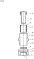
- die Klemmvorrichtung in einer Explosionsansicht; und
- Fig. 6
- einen Längsschnitt einer Anordnung des Trägers und der Klemmvorrichtung, die an dem Träger befestigt ist.
- Die Erfindung wird anhand der
Figuren 1 bis 6 am Beispiel einer Messanordnung 10 erläutert, die einen Längenmesstaster 12 mit einem Schaft 14 und einen darin in Längsrichtung X geführten Taststift 16 umfasst. Zum Messbetrieb ist der Längenmesstaster 12 an einem stationären Träger 18 befestigt, indem der Schaft 14 des Längenmesstasters 12 durch eine erfindungsgemäße Klemmvorrichtung 20 umfangsmäßig geklemmt ist. Die Klemmvorrichtung 20 ist dazu ausgebildet, den Schaft 14 des Längenmesstasters 12 einerseits ortsfest am Träger 18 zu halten und andererseits auf den Schaft 14 des Längenmesstasters 12 über den Umfang eine in Abhängigkeit der Temperatur im Wesentlichen konstante Klemmkraft bzw. Spannkraft auszuüben. - Die Klemmvorrichtung 20 wird nachfolgend anhand der
Figuren 3 bis 5 näher erläutert. Die Klemmvorrichtung 20 umfasst eine Klemmhülse 22, ein erstes Verbindungselement 24, ein zweites Verbindungselement 26, ein Gleitringelement 34 und ein Kompressionselement 38. - Die Klemmhülse 22 dient zum Umgreifen des Schaftes 14 des Längenmesstasters 12. Die Klemmhülse 22 ist derart elastisch verformbar, dass sie gegen den Schaft 14 des Längenmesstasters 12 andrückbar ist. Das erste Verbindungselement 24 umgibt die Klemmhülse 22 derart, dass zumindest entlang eines Längsabschnitts der Klemmvorrichtung 20 zwischen der Klemmhülse 22 und dem ersten Verbindungselement 24 ein hohlzylinderförmiger Zwischenraum 28 gebildet wird. Das zweite Verbindungselement 26 ist an einem Ende des ersten Verbindungselements 24 drehbar befestigt. Das Gleitringelement 34 ist an einem dem zweiten Verbindungselement 26 zugewandten Ende der Klemmhülse 22 zwischen der Klemmhülse 22 und dem ersten Verbindungselement 24 einerseits und zwischen dem hohlzylinderförmigen Zwischenraum 28 und einem Druckbeaufschlagungsteil 36 der Klemmvorrichtung 20 andererseits angeordnet. Das Druckbeaufschlagungsteil 36 ist ein hohlzylinderförmiger Abschnitt des zweiten Verbindungselements 26, der an einer dem hohlzylinderförmigen Zwischenraum 28 gegenüberliegenden Seite an das Gleitringelement 34 angrenzt. Das Kompressionselement 38 ist in den hohlzylinderförmigen Zwischenraum 28 eingebracht.
- Das erste Verbindungselement 24 ist ein im Wesentlichen hohlzylinderförmiges Gehäuseteil. Das zweite Verbindungselement 26 ist eine mit dem ersten Verbindungselement 24 verschraubbare Mutter. Zum Verschrauben hat das erste Verbindungselement 24 ein an dem dem zweiten Verbindungselement 26 zugewandten Ende des ersten Verbindungselements 24 vorgesehenes erstes Außengewinde 30.1, das mit einem Innengewinde 32 des zweiten Verbindungselements 26 in Eingriff steht. Das erste Verbindungselement 24 kann an einem dem zweiten Verbindungselement 26 abgewandten Ende des ersten Verbindungselements 24 mit einem oberen Randabschnitt der Klemmhülse 22 verschraubt sein. Die Klemmhülse 22 kann alternativ auch ohne Verschrauben in das erste Verbindungselement 24 eingesetzt sein.
- Der Montagezustand der Klemmvorrichtung 20 ist insbesondere in
Figur 4 dargestellt. Die Klemmvorrichtung 20 ist derart ausgebildet, dass bei einem Verdrehen des zweiten Verbindungselements 26 relativ zum ersten Verbindungselement 24 das Druckbeaufschlagungsteil 36 eine in Richtung des Kompressionselements 38 gerichtete Axialkraft auf das Gleitringelement 34 ausübt und dadurch das Gleitringelement 34 gegen das Kompressionselement 38 bewegt, wodurch die Axialkraft auf das Kompressionselement 38 übertragen wird. Das Kompressionselement 38 ist derart ausgebildet, dass es bei einem Erfahren der Axialkraft eine in Richtung des Schaftes 14 des Längenmesstasters 12 gerichtete Radialkraft FR auf die Klemmhülse 22 ausübt und dadurch die Klemmhülse 22 gegen den Schaft 14 des Längenmesstasters 12 andrückt. Erfindungsgemäß hat das Kompressionselement 38 einen thermischen Ausdehnungskoeffizienten, der derart an die thermischen Ausdehnungskoeffizienten der Klemmhülse 22 und des ersten Verbindungselements 24 angepasst ist, dass eine durch eine Temperaturänderung bedingte Änderung der Radialkraft FR vermieden oder zumindest verringert wird. Dadurch wird erreicht, dass die Klemmvorrichtung 20 unempfindlich gegen Temperaturschwankungen ist. - Das Kompressionselement 38 weist ein Fasern 40, vorzugsweise Glasfasern, umfassendes Material auf. Vorzugsweise hat das Kompressionselement 38 somit den thermischen Längenausdehnungskoeffizienten 8,5 x 10⁻⁶K-1. Die Klemmhülse 22 und das erste Verbindungselement 24 sind vorzugsweise aus Stahl mit dem thermischen Längenausdehnungskoeffizienten 10 x 10-6 K-1 gefertigt. Ferner können auch das zweite Verbindungselement 26 und das Gleitringelement 34 aus Stahl mit demselben thermischen Längenausdehnungskoeffizienten gefertigt sein. Infolgedessen hat das Kompressionselement 38 einen vergleichbaren oder ähnlichen thermischen Längenausdehnungskoeffizienten wie zumindest die Klemmhülse 22 und das erste Verbindungselement 24. Dies ist gegenüber dem Einsatz einer Hydraulikflüssigkeit, wie beispielsweise eines Hydrauliköls, als Kompressionselement von Vorteil, da die Hydraulikflüssigkeit im Vergleich zu Stahl typischerweise einen viel größeren thermischen Längenausdehnungskoeffizienten hat. In diesem Fall wäre die Unempfindlichkeit gegen Temperaturschwankungen der Klemmvorrichtung 20 nicht mehr gegeben.
- In vorteilhafter Weise ist das Kompressionselement 38 ein aus Glasfaser-Roving hergestellter Wickelkörper. Dadurch kann das Kompressionselement 38 zu einem gewissen Grad kompressibel ausgebildet sein, wodurch bei einer Druckbeaufschlagung in axialer Richtung die Radialkraft FR bewirkt wird.
- Das Kompressionselement 38 ist in vorteilhafter Weise zudem reversibel verformbar. Beim Verdrehen des zweiten Verbindungselements 26 relativ zum ersten Verbindungselement 24 in eine erste Drehrichtung wechselt es von einem ersten Verformungszustand in einen zweiten Verformungszustand. Beim Verdrehen des zweiten Verbindungselements 26 relativ zum ersten Verbindungselement 24 in eine zur ersten Drehrichtung entgegengesetzte zweite Richtung wechselt es wieder vom zweiten Verformungszustand in den ersten Verformungszustand. Das Verdrehen erfolgt dabei um die Rotationsachse S, wie es in
Figur 4 durch den Pfeil R angedeutet ist. - Durch die reversible Verformbarkeit des Kompressionselements 38 wird ein Feststopfen des Fasermaterials verhindert. Somit bleibt beim Lösen der Verbindung zwischen dem ersten Verbindungselement 24 und dem zweiten Verbindungselement 26 die Radialkraft FR nicht erhalten, so dass der Schaft 14 des Längenmesstasters 12 wieder freigebbar ist.
- In der Explosionsansicht der
Figur 5 sind die einzelnen Bauteile der Klemmvorrichtung 20 dargestellt. Zur Montage bzw. Herstellung der Klemmvorrichtung 20 erfolgen die folgenden Schritte. Es wird das erste Verbindungselement 24 bereitgestellt, das am unteren Ende das erste Außengewinde 30.1 und am oberen Ende ein zweites Außengewinde 30.2 und ein Innengewinde 30.3 aufweist. Es wird zudem die Klemmhülse 22 bereitgestellt, die am oberen Randabschnitt ein Außengewinde 42 aufweist. Die Klemmhülse 22 wird in das erste Verbindungselement 24 eingesetzt und durch die miteinander in Eingriff stehenden Gewinde 42 und 30.3 verschraubt. Das die Fasern 40 enthaltende Kompressionselement 38 wird in vorteilhafter Weise unabhängig von der Klemmhülse 22 als separates Element zur Verfügung gestellt. Das Kompressionselement 38 wird zwischen die Klemmhülse 22 und das erste Verbindungselement 24 eingebracht. Es werden zudem das Gleitringelement 34 und das zweite Verbindungselement 26 bereitgestellt. Das zweite Verbindungselement 26 weist das Druckbeaufschlagungsteil 36 auf. Das erste Verbindungselement 24 und das zweite Verbindungselement 26 werden durch die miteinander in Eingriff stehenden Gewinde 30.1 und 32 verschraubt. Dabei wird das Gleitringelement 34 einerseits zwischen die Klemmhülse 22 und das erste Verbindungselement 24 eingebracht und andererseits durch das Druckbeaufschlagungsteil 36 gegen das Kompressionselement 38 bewegt. - Durch das Bereitstellen des Kompressionselements 38 als separates Element wird die Montage vereinfacht. Das Kompressionselement 38 kann alternativ auch durch direkt auf die Klemmhülse 22 gewickelte Fasern 40 gebildet sein.
-
Figur 6 zeigt einen Längsschnitt einer Anordnung des Trägers 18 und der Klemmvorrichtung 20, die an dem Träger 18 befestigt ist. Zur Befestigung dient das am oberen Ende der Klemmvorrichtung 20 vorgesehene zweite Außengewinde 30.2, das mit einem Innengewinde 44 einer Durchgangsbohrung des Trägers 18 in Eingriff gebracht werden kann. - Die erfindungsgemäße Klemmvorrichtung 20 hat gegenüber konventionellen hydraulischen Klemm- bzw. Spannelementen, wie beispielsweise einem Hydrodehnspannfutter, die folgenden Vorteile. Es erfolgt keine Schwankung der Klemm- bzw. Spannkraft bei Temperaturwechselzyklen. Die Klemmvorrichtung 20 ist flüssigkeitsfrei. Somit kann sie nicht undicht werden und damit ihre Klemm- bzw. Spannkraft verlieren. Es gibt keine Gefahr der Kontamination der Umgebung bei einer Undichtigkeit des Systems. Die Klemmvorrichtung 20 ist daher auch in steriler Umgebung einsetzbar. Die Klemmvorrichtung 20 ist zudem vakuumgeeignet und hochtemperaturgeeignet. Im Gegensatz zu hydraulischen Systemen ist die Klemmvorrichtung 20 für Temperaturen ausgelegt, die viel höher als 150 °C sind.
-
- 10
- Messanordnung
- 12
- Längenmesstaster
- 14
- Schaft
- 16
- Taststift
- 18
- Träger
- 20
- Klemmvorrichtung
- 22
- Klemmhülse
- 24
- Verbindungselement
- 26
- Verbindungselement
- 28
- hohlzylinderförmiger Zwischenraum
- 30.1
- Außengewinde
- 30.2
- Außengewinde
- 30.3
- Innengewinde
- 32
- Innengewinde
- 34
- Gleitringelement
- 36
- Druckbeaufschlagungsteil
- 38
- Kompressionselement
- 40
- Fasern
- 42
- Außengewinde
- 44
- Innengewinde
- FR
- Radialkraft
- R
- Pfeil
- S
- Rotationsachse
- X
- Längsrichtung
Claims (15)
- Klemmvorrichtung (20) zum Befestigung eines Messtasters, insbesondere eines Längenmesstasters (12), an einem Träger (18), mit
einer Klemmhülse (22) zum Umgreifen eines Schaftes (14) des Messtasters, wobei die Klemmhülse (22) derart elastisch verformbar ist, dass sie gegen den Schaft (14) des Messtasters andrückbar ist,
einem ersten Verbindungselement (24), das die Klemmhülse (22) derart umgibt, dass zumindest entlang eines Längsabschnitts der Klemmvorrichtung (20) zwischen der Klemmhülse (22) und dem ersten Verbindungselement (24) ein hohlzylinderförmiger Zwischenraum (28) gebildet wird,
einem zweiten Verbindungselement (26), wobei das erste Verbindungselement (24) und das zweite Verbindungselement (26) drehbar aneinander befestigt sind,
einem Gleitringelement (34), das zwischen der Klemmhülse (22) und dem ersten Verbindungselement (24) einerseits und zwischen dem hohlzylinderförmigen Zwischenraum (28) und einem Druckbeaufschlagungsteil (36) der Klemmvorrichtung (20) andererseits angeordnet ist, und
einem Kompressionselement (38), das in den hohlzylinderförmigen Zwischenraum (28) eingebracht ist,
wobei die Klemmvorrichtung (20) derart ausgebildet ist, dass bei einem Verdrehen der beiden Verbindungselemente (24, 26) relativ zueinander das Druckbeaufschlagungsteil (36) eine in Richtung des Kompressionselements (38) gerichtete Axialkraft auf das Gleitringelement (34) ausübt und dadurch das Gleitringelement (34) gegen das Kompressionselement (38) bewegt, wodurch die Axialkraft auf das Kompressionselement (38) übertragen wird,
wobei das Kompressionselement (38) derart ausgebildet ist, dass es bei einem Erfahren der Axialkraft eine in Richtung des Schaftes (14) des Messtasters gerichtete Radialkraft (FR) auf die Klemmhülse (22) ausübt und dadurch die Klemmhülse (22) gegen den Schaft (14) des Messtasters andrückt, und
wobei das Kompressionselement (38) einen thermischen Ausdehnungskoeffizienten hat, der derart an die thermischen Ausdehnungskoeffizienten der Klemmhülse (22) und des ersten Verbindungselements (24) angepasst ist, dass eine durch eine Temperaturänderung bedingte Änderung der Radialkraft (FR) vermieden oder zumindest verringert wird. - Klemmvorrichtung (20) nach Anspruch 1, wobei das Kompressionselement (38) einen thermischen Längenausdehnungskoeffizienten im Bereich von 8 bis 25 x 10-6K-1 oder im Bereich von 9 bis 12 x 10-6K-1 hat.
- Klemmvorrichtung (20) nach Anspruch 1 oder 2, wobei das Kompressionselement (38) ein Fasern (20) umfassendes Material aufweist.
- Klemmvorrichtung (20) nach einem der vorhergehenden Ansprüche, wobei das Kompressionselement (38) ein unabhängig von der Klemmhülse (22) aus Fasern (40) hergestellter Wickelkörper ist oder durch auf die Klemmhülse (22) gewickelte Fasern gebildet ist.
- Klemmvorrichtung (20) nach einem der vorhergehenden Ansprüche, wobei das Kompressionselement (38) Glasfaser-Roving, Kohlefaser-Roving Glaspulver, Glaskugeln, Stahldraht, Stahlpulver, Stahlkugeln oder einen Kunststoff mit einem bestimmten Glasfaseranteil umfasst.
- Klemmvorrichtung (20) nach einem der vorhergehenden Ansprüche, wobei das Kompressionselement (38) ein elastisch verformbares Festkörperelement ist.
- Klemmvorrichtung (20) nach einem der vorhergehenden Ansprüche, wobei das Kompressionselement (38) derart reversibel verformbar ist, dass es beim Verdrehen des zweiten Verbindungselements (26) relativ zum ersten Verbindungselement (24) in eine erste Drehrichtung von einem ersten Verformungszustand in einen zweiten Verformungszustand wechselt, und dass es beim Verdrehen des zweiten Verbindungselements (26) relativ zum ersten Verbindungselement (24) in eine zur ersten Drehrichtung entgegengesetzte zweite Drehrichtung wieder vom zweiten Verformungszustand in den ersten Verformungszustand wechselt.
- Klemmvorrichtung (20) nach einem der vorhergehenden Ansprüche, wobei das erste Verbindungselement (24) ein Bauteil mit Außengewinde und das zweite Verbindungselement (26) ein Bauteil mit Innengewinde sind.
- Klemmvorrichtung (20) nach einem der vorhergehenden Ansprüche, wobei das erste Verbindungselement (24) ein an einem dem zweiten Verbindungselement (26) zugewandten Ende des ersten Verbindungselements (24) vorgesehenes erstes Außengewinde (30.1) hat, das mit einem Innengewinde (32) des zweiten Verbindungselements (26) in Eingriff steht.
- Klemmvorrichtung (20) nach einem der vorhergehenden Ansprüche, wobei das erste Verbindungselement (24) ein an einem dem zweiten Verbindungselement (26) abgewandten Ende des ersten Verbindungselements (24) vorgesehenes zweites Außengewinde (30.2) hat, das derart ausgebildet ist, dass es mit einem Innengewinde (44) einer Durchgangsbohrung des Trägers (18) in Eingriff gebracht werden kann.
- Klemmvorrichtung (20) nach einem der vorhergehenden Ansprüche, wobei das Druckbeaufschlagungsteil (36) einstückig mit dem zweiten Verbindungselement (26) gebildet ist.
- Klemmvorrichtung (20) nach einem der vorhergehenden Ansprüche, wobei der hohlzylinderförmige Zwischenraum (28) flüssigkeitsfrei ist.
- Klemmvorrichtung (20) nach einem der vorhergehenden Ansprüche, wobei die Klemmhülse (22), das erste Verbindungselement (24), das zweite Verbindungselement (26) und/oder das Gleitringelement (34) einen thermischen Längenausdehnungskoeffizienten im Bereich von 8 bis 25 x 10-6K-1 oder im Bereich von 9 bis 12 x 10-6K-1 haben.
- Klemmvorrichtung (20) nach einem der vorhergehenden Ansprüche, wobei die Klemmhülse (22), das erste Verbindungselement (24), das zweite Verbindungselement (26) und/oder das Gleitringelement (34) aus Stahl, Messing, Aluminium oder Invar gefertigt sind.
- Messanordnung (10) mit einem Messtaster, insbesondere einem Längenmesstaster (12), einem Träger (18) und einer Klemmvorrichtung (20) nach einem der vorhergehenden Ansprüche.
Applications Claiming Priority (1)
| Application Number | Priority Date | Filing Date | Title |
|---|---|---|---|
| DE102018220437.3A DE102018220437A1 (de) | 2018-11-28 | 2018-11-28 | Klemmvorrichtung |
Publications (2)
| Publication Number | Publication Date |
|---|---|
| EP3660445A1 true EP3660445A1 (de) | 2020-06-03 |
| EP3660445B1 EP3660445B1 (de) | 2021-08-18 |
Family
ID=68137828
Family Applications (1)
| Application Number | Title | Priority Date | Filing Date |
|---|---|---|---|
| EP19200139.4A Active EP3660445B1 (de) | 2018-11-28 | 2019-09-27 | Klemmvorrichtung |
Country Status (3)
| Country | Link |
|---|---|
| EP (1) | EP3660445B1 (de) |
| JP (1) | JP7402010B2 (de) |
| DE (1) | DE102018220437A1 (de) |
Citations (3)
| Publication number | Priority date | Publication date | Assignee | Title |
|---|---|---|---|---|
| JPS63318305A (ja) * | 1987-06-18 | 1988-12-27 | 株式会社日本製鋼所 | ロッドクランプ装置 |
| US4848953A (en) * | 1988-04-22 | 1989-07-18 | Niels Young | Clamp assembly |
| DE102016219714A1 (de) | 2016-10-11 | 2018-04-12 | Dr. Johannes Heidenhain Gesellschaft Mit Beschränkter Haftung | Klemmvorrichtung |
Family Cites Families (2)
| Publication number | Priority date | Publication date | Assignee | Title |
|---|---|---|---|---|
| US4786397A (en) * | 1987-10-09 | 1988-11-22 | Allied-Signal Inc. | Seal for single wire O2 sensor |
| JP6422316B2 (ja) * | 2014-11-27 | 2018-11-14 | Dmg森精機株式会社 | 接触式測長器の保持装置 |
-
2018
- 2018-11-28 DE DE102018220437.3A patent/DE102018220437A1/de not_active Withdrawn
-
2019
- 2019-09-27 EP EP19200139.4A patent/EP3660445B1/de active Active
- 2019-10-24 JP JP2019193128A patent/JP7402010B2/ja active Active
Patent Citations (3)
| Publication number | Priority date | Publication date | Assignee | Title |
|---|---|---|---|---|
| JPS63318305A (ja) * | 1987-06-18 | 1988-12-27 | 株式会社日本製鋼所 | ロッドクランプ装置 |
| US4848953A (en) * | 1988-04-22 | 1989-07-18 | Niels Young | Clamp assembly |
| DE102016219714A1 (de) | 2016-10-11 | 2018-04-12 | Dr. Johannes Heidenhain Gesellschaft Mit Beschränkter Haftung | Klemmvorrichtung |
Also Published As
| Publication number | Publication date |
|---|---|
| JP7402010B2 (ja) | 2023-12-20 |
| JP2020085893A (ja) | 2020-06-04 |
| DE102018220437A1 (de) | 2020-05-28 |
| EP3660445B1 (de) | 2021-08-18 |
Similar Documents
| Publication | Publication Date | Title |
|---|---|---|
| DE10042844C1 (de) | Radial justierbare Linsenfassung | |
| DE102010050175B4 (de) | Kugelgewindemutter | |
| DE2549484C2 (de) | Anordnung zum Koppeln optischer Fasern | |
| EP0645548A1 (de) | Kupplungsvorrichtung | |
| CH682688A5 (de) | Schaftanordnung mit wenigstens einem Kugel- oder Rollenlager. | |
| DE69300481T2 (de) | Führungselement eines verschiebbaren sattels für scheibenbremse. | |
| DE102007029449A1 (de) | Fliehkraftunterstütztes Werkzeugspannsystem | |
| DE3249120C2 (de) | ||
| EP3876372A1 (de) | Explosionsgeschützte vorrichtung | |
| EP3456986B1 (de) | Führungseinheit mit zwei parallel und im abstand zueinander angeordneten kreiszylinderförmigen führungselementen | |
| EP1380763B1 (de) | Welle-Nabeverbindung | |
| DE69008091T2 (de) | Rolle mit konischem Schaft. | |
| DE10230158B4 (de) | Klemm-Mechanismus für eine Lenksäule | |
| EP0854076A1 (de) | Verfahren und Vorrichtung zum Einpressen einer vormontierten Kugelgelenk-Patrone in ein Lagerauge eines Lenkerhebels | |
| DE19807455B4 (de) | Spannfutter | |
| DE102019115387A1 (de) | Spannvorrichtung zum Einspannen eines Gegenstands, insbesondere eines Werkzeugs | |
| EP3660445B1 (de) | Klemmvorrichtung | |
| EP3774497B1 (de) | Lenkvorrichtung mit simuliertem lenkwiderstandsmoment | |
| DE102012212023A1 (de) | Kabelverschraubung | |
| EP1201944B1 (de) | Verbindungselement | |
| EP3475601B1 (de) | Anschlusseinrichtung zur realisierung eines drehanschlusses für eine anschlusskomponente | |
| DE102019111144A1 (de) | Spindeltrieb mit Verdrehsicherung | |
| DE202019100248U1 (de) | Klemmvorrichtung | |
| DE19901562A1 (de) | Wellenlageranordnung mit Spielausgleich | |
| DE102018131864A1 (de) | Lagereinheit für eine Schneckenwelle eines Lenkgetriebes |
Legal Events
| Date | Code | Title | Description |
|---|---|---|---|
| PUAI | Public reference made under article 153(3) epc to a published international application that has entered the european phase |
Free format text: ORIGINAL CODE: 0009012 |
|
| STAA | Information on the status of an ep patent application or granted ep patent |
Free format text: STATUS: REQUEST FOR EXAMINATION WAS MADE |
|
| 17P | Request for examination filed |
Effective date: 20190927 |
|
| AK | Designated contracting states |
Kind code of ref document: A1 Designated state(s): AL AT BE BG CH CY CZ DE DK EE ES FI FR GB GR HR HU IE IS IT LI LT LU LV MC MK MT NL NO PL PT RO RS SE SI SK SM TR |
|
| AX | Request for extension of the european patent |
Extension state: BA ME |
|
| STAA | Information on the status of an ep patent application or granted ep patent |
Free format text: STATUS: EXAMINATION IS IN PROGRESS |
|
| 17Q | First examination report despatched |
Effective date: 20200609 |
|
| RBV | Designated contracting states (corrected) |
Designated state(s): AL AT BE BG CH CY CZ DE DK EE ES FI FR GB GR HR HU IE IS IT LI LT LU LV MC MK MT NL NO PL PT RO RS SE SI SK SM TR |
|
| GRAP | Despatch of communication of intention to grant a patent |
Free format text: ORIGINAL CODE: EPIDOSNIGR1 |
|
| STAA | Information on the status of an ep patent application or granted ep patent |
Free format text: STATUS: GRANT OF PATENT IS INTENDED |
|
| RIC1 | Information provided on ipc code assigned before grant |
Ipc: G01B 5/00 20060101AFI20210222BHEP |
|
| INTG | Intention to grant announced |
Effective date: 20210315 |
|
| GRAS | Grant fee paid |
Free format text: ORIGINAL CODE: EPIDOSNIGR3 |
|
| GRAA | (expected) grant |
Free format text: ORIGINAL CODE: 0009210 |
|
| STAA | Information on the status of an ep patent application or granted ep patent |
Free format text: STATUS: THE PATENT HAS BEEN GRANTED |
|
| AK | Designated contracting states |
Kind code of ref document: B1 Designated state(s): AL AT BE BG CH CY CZ DE DK EE ES FI FR GB GR HR HU IE IS IT LI LT LU LV MC MK MT NL NO PL PT RO RS SE SI SK SM TR |
|
| REG | Reference to a national code |
Ref country code: GB Ref legal event code: FG4D Free format text: NOT ENGLISH |
|
| REG | Reference to a national code |
Ref country code: CH Ref legal event code: EP |
|
| REG | Reference to a national code |
Ref country code: DE Ref legal event code: R096 Ref document number: 502019002075 Country of ref document: DE |
|
| REG | Reference to a national code |
Ref country code: IE Ref legal event code: FG4D Free format text: LANGUAGE OF EP DOCUMENT: GERMAN Ref country code: AT Ref legal event code: REF Ref document number: 1422018 Country of ref document: AT Kind code of ref document: T Effective date: 20210915 |
|
| REG | Reference to a national code |
Ref country code: LT Ref legal event code: MG9D |
|
| REG | Reference to a national code |
Ref country code: NL Ref legal event code: MP Effective date: 20210818 |
|
| PG25 | Lapsed in a contracting state [announced via postgrant information from national office to epo] |
Ref country code: SE Free format text: LAPSE BECAUSE OF FAILURE TO SUBMIT A TRANSLATION OF THE DESCRIPTION OR TO PAY THE FEE WITHIN THE PRESCRIBED TIME-LIMIT Effective date: 20210818 Ref country code: RS Free format text: LAPSE BECAUSE OF FAILURE TO SUBMIT A TRANSLATION OF THE DESCRIPTION OR TO PAY THE FEE WITHIN THE PRESCRIBED TIME-LIMIT Effective date: 20210818 Ref country code: FI Free format text: LAPSE BECAUSE OF FAILURE TO SUBMIT A TRANSLATION OF THE DESCRIPTION OR TO PAY THE FEE WITHIN THE PRESCRIBED TIME-LIMIT Effective date: 20210818 Ref country code: ES Free format text: LAPSE BECAUSE OF FAILURE TO SUBMIT A TRANSLATION OF THE DESCRIPTION OR TO PAY THE FEE WITHIN THE PRESCRIBED TIME-LIMIT Effective date: 20210818 Ref country code: BG Free format text: LAPSE BECAUSE OF FAILURE TO SUBMIT A TRANSLATION OF THE DESCRIPTION OR TO PAY THE FEE WITHIN THE PRESCRIBED TIME-LIMIT Effective date: 20211118 Ref country code: LT Free format text: LAPSE BECAUSE OF FAILURE TO SUBMIT A TRANSLATION OF THE DESCRIPTION OR TO PAY THE FEE WITHIN THE PRESCRIBED TIME-LIMIT Effective date: 20210818 Ref country code: NO Free format text: LAPSE BECAUSE OF FAILURE TO SUBMIT A TRANSLATION OF THE DESCRIPTION OR TO PAY THE FEE WITHIN THE PRESCRIBED TIME-LIMIT Effective date: 20211118 Ref country code: PT Free format text: LAPSE BECAUSE OF FAILURE TO SUBMIT A TRANSLATION OF THE DESCRIPTION OR TO PAY THE FEE WITHIN THE PRESCRIBED TIME-LIMIT Effective date: 20211220 Ref country code: HR Free format text: LAPSE BECAUSE OF FAILURE TO SUBMIT A TRANSLATION OF THE DESCRIPTION OR TO PAY THE FEE WITHIN THE PRESCRIBED TIME-LIMIT Effective date: 20210818 |
|
| PG25 | Lapsed in a contracting state [announced via postgrant information from national office to epo] |
Ref country code: PL Free format text: LAPSE BECAUSE OF FAILURE TO SUBMIT A TRANSLATION OF THE DESCRIPTION OR TO PAY THE FEE WITHIN THE PRESCRIBED TIME-LIMIT Effective date: 20210818 Ref country code: LV Free format text: LAPSE BECAUSE OF FAILURE TO SUBMIT A TRANSLATION OF THE DESCRIPTION OR TO PAY THE FEE WITHIN THE PRESCRIBED TIME-LIMIT Effective date: 20210818 Ref country code: GR Free format text: LAPSE BECAUSE OF FAILURE TO SUBMIT A TRANSLATION OF THE DESCRIPTION OR TO PAY THE FEE WITHIN THE PRESCRIBED TIME-LIMIT Effective date: 20211119 |
|
| PG25 | Lapsed in a contracting state [announced via postgrant information from national office to epo] |
Ref country code: NL Free format text: LAPSE BECAUSE OF FAILURE TO SUBMIT A TRANSLATION OF THE DESCRIPTION OR TO PAY THE FEE WITHIN THE PRESCRIBED TIME-LIMIT Effective date: 20210818 |
|
| PG25 | Lapsed in a contracting state [announced via postgrant information from national office to epo] |
Ref country code: DK Free format text: LAPSE BECAUSE OF FAILURE TO SUBMIT A TRANSLATION OF THE DESCRIPTION OR TO PAY THE FEE WITHIN THE PRESCRIBED TIME-LIMIT Effective date: 20210818 |
|
| REG | Reference to a national code |
Ref country code: DE Ref legal event code: R097 Ref document number: 502019002075 Country of ref document: DE |
|
| REG | Reference to a national code |
Ref country code: BE Ref legal event code: MM Effective date: 20210930 |
|
| PG25 | Lapsed in a contracting state [announced via postgrant information from national office to epo] |
Ref country code: SM Free format text: LAPSE BECAUSE OF FAILURE TO SUBMIT A TRANSLATION OF THE DESCRIPTION OR TO PAY THE FEE WITHIN THE PRESCRIBED TIME-LIMIT Effective date: 20210818 Ref country code: SK Free format text: LAPSE BECAUSE OF FAILURE TO SUBMIT A TRANSLATION OF THE DESCRIPTION OR TO PAY THE FEE WITHIN THE PRESCRIBED TIME-LIMIT Effective date: 20210818 Ref country code: RO Free format text: LAPSE BECAUSE OF FAILURE TO SUBMIT A TRANSLATION OF THE DESCRIPTION OR TO PAY THE FEE WITHIN THE PRESCRIBED TIME-LIMIT Effective date: 20210818 Ref country code: MC Free format text: LAPSE BECAUSE OF FAILURE TO SUBMIT A TRANSLATION OF THE DESCRIPTION OR TO PAY THE FEE WITHIN THE PRESCRIBED TIME-LIMIT Effective date: 20210818 Ref country code: EE Free format text: LAPSE BECAUSE OF FAILURE TO SUBMIT A TRANSLATION OF THE DESCRIPTION OR TO PAY THE FEE WITHIN THE PRESCRIBED TIME-LIMIT Effective date: 20210818 Ref country code: CZ Free format text: LAPSE BECAUSE OF FAILURE TO SUBMIT A TRANSLATION OF THE DESCRIPTION OR TO PAY THE FEE WITHIN THE PRESCRIBED TIME-LIMIT Effective date: 20210818 Ref country code: AL Free format text: LAPSE BECAUSE OF FAILURE TO SUBMIT A TRANSLATION OF THE DESCRIPTION OR TO PAY THE FEE WITHIN THE PRESCRIBED TIME-LIMIT Effective date: 20210818 |
|
| PLBE | No opposition filed within time limit |
Free format text: ORIGINAL CODE: 0009261 |
|
| STAA | Information on the status of an ep patent application or granted ep patent |
Free format text: STATUS: NO OPPOSITION FILED WITHIN TIME LIMIT |
|
| 26N | No opposition filed |
Effective date: 20220519 |
|
| PG25 | Lapsed in a contracting state [announced via postgrant information from national office to epo] |
Ref country code: LU Free format text: LAPSE BECAUSE OF NON-PAYMENT OF DUE FEES Effective date: 20210927 Ref country code: IT Free format text: LAPSE BECAUSE OF FAILURE TO SUBMIT A TRANSLATION OF THE DESCRIPTION OR TO PAY THE FEE WITHIN THE PRESCRIBED TIME-LIMIT Effective date: 20210818 Ref country code: IE Free format text: LAPSE BECAUSE OF NON-PAYMENT OF DUE FEES Effective date: 20210927 Ref country code: BE Free format text: LAPSE BECAUSE OF NON-PAYMENT OF DUE FEES Effective date: 20210930 |
|
| PG25 | Lapsed in a contracting state [announced via postgrant information from national office to epo] |
Ref country code: SI Free format text: LAPSE BECAUSE OF FAILURE TO SUBMIT A TRANSLATION OF THE DESCRIPTION OR TO PAY THE FEE WITHIN THE PRESCRIBED TIME-LIMIT Effective date: 20210818 |
|
| PG25 | Lapsed in a contracting state [announced via postgrant information from national office to epo] |
Ref country code: FR Free format text: LAPSE BECAUSE OF NON-PAYMENT OF DUE FEES Effective date: 20211018 |
|
| PG25 | Lapsed in a contracting state [announced via postgrant information from national office to epo] |
Ref country code: CY Free format text: LAPSE BECAUSE OF FAILURE TO SUBMIT A TRANSLATION OF THE DESCRIPTION OR TO PAY THE FEE WITHIN THE PRESCRIBED TIME-LIMIT Effective date: 20210818 |
|
| PG25 | Lapsed in a contracting state [announced via postgrant information from national office to epo] |
Ref country code: HU Free format text: LAPSE BECAUSE OF FAILURE TO SUBMIT A TRANSLATION OF THE DESCRIPTION OR TO PAY THE FEE WITHIN THE PRESCRIBED TIME-LIMIT; INVALID AB INITIO Effective date: 20190927 |
|
| PG25 | Lapsed in a contracting state [announced via postgrant information from national office to epo] |
Ref country code: MK Free format text: LAPSE BECAUSE OF FAILURE TO SUBMIT A TRANSLATION OF THE DESCRIPTION OR TO PAY THE FEE WITHIN THE PRESCRIBED TIME-LIMIT Effective date: 20210818 |
|
| GBPC | Gb: european patent ceased through non-payment of renewal fee |
Effective date: 20230927 |
|
| PG25 | Lapsed in a contracting state [announced via postgrant information from national office to epo] |
Ref country code: TR Free format text: LAPSE BECAUSE OF FAILURE TO SUBMIT A TRANSLATION OF THE DESCRIPTION OR TO PAY THE FEE WITHIN THE PRESCRIBED TIME-LIMIT Effective date: 20210818 |
|
| PG25 | Lapsed in a contracting state [announced via postgrant information from national office to epo] |
Ref country code: GB Free format text: LAPSE BECAUSE OF NON-PAYMENT OF DUE FEES Effective date: 20230927 |
|
| PG25 | Lapsed in a contracting state [announced via postgrant information from national office to epo] |
Ref country code: GB Free format text: LAPSE BECAUSE OF NON-PAYMENT OF DUE FEES Effective date: 20230927 |
|
| PG25 | Lapsed in a contracting state [announced via postgrant information from national office to epo] |
Ref country code: MT Free format text: LAPSE BECAUSE OF FAILURE TO SUBMIT A TRANSLATION OF THE DESCRIPTION OR TO PAY THE FEE WITHIN THE PRESCRIBED TIME-LIMIT Effective date: 20210818 |
|
| REG | Reference to a national code |
Ref country code: CH Ref legal event code: U11 Free format text: ST27 STATUS EVENT CODE: U-0-0-U10-U11 (AS PROVIDED BY THE NATIONAL OFFICE) Effective date: 20251001 |
|
| PGFP | Annual fee paid to national office [announced via postgrant information from national office to epo] |
Ref country code: DE Payment date: 20250919 Year of fee payment: 7 |
|
| REG | Reference to a national code |
Ref country code: AT Ref legal event code: MM01 Ref document number: 1422018 Country of ref document: AT Kind code of ref document: T Effective date: 20240927 |
|
| REG | Reference to a national code |
Ref country code: CH Ref legal event code: R17 Free format text: ST27 STATUS EVENT CODE: U-0-0-R10-R17 (AS PROVIDED BY THE NATIONAL OFFICE) Effective date: 20260108 |
|
| PG25 | Lapsed in a contracting state [announced via postgrant information from national office to epo] |
Ref country code: AT Free format text: LAPSE BECAUSE OF NON-PAYMENT OF DUE FEES Effective date: 20240927 |
|
| PGFP | Annual fee paid to national office [announced via postgrant information from national office to epo] |
Ref country code: CH Payment date: 20251001 Year of fee payment: 7 |
|
| PGFP | Annual fee paid to national office [announced via postgrant information from national office to epo] |
Ref country code: AT Payment date: 20260410 Year of fee payment: 5 |