EP3660406A1 - Air conditioner - Google Patents
Air conditioner Download PDFInfo
- Publication number
- EP3660406A1 EP3660406A1 EP17918831.3A EP17918831A EP3660406A1 EP 3660406 A1 EP3660406 A1 EP 3660406A1 EP 17918831 A EP17918831 A EP 17918831A EP 3660406 A1 EP3660406 A1 EP 3660406A1
- Authority
- EP
- European Patent Office
- Prior art keywords
- switch
- outdoor unit
- indoor unit
- terminal
- connection terminal
- Prior art date
- Legal status (The legal status is an assumption and is not a legal conclusion. Google has not performed a legal analysis and makes no representation as to the accuracy of the status listed.)
- Granted
Links
Images


Classifications
-
- F—MECHANICAL ENGINEERING; LIGHTING; HEATING; WEAPONS; BLASTING
- F24—HEATING; RANGES; VENTILATING
- F24F—AIR-CONDITIONING; AIR-HUMIDIFICATION; VENTILATION; USE OF AIR CURRENTS FOR SCREENING
- F24F1/00—Room units for air-conditioning, e.g. separate or self-contained units or units receiving primary air from a central station
- F24F1/0003—Room units for air-conditioning, e.g. separate or self-contained units or units receiving primary air from a central station characterised by a split arrangement, wherein parts of the air-conditioning system, e.g. evaporator and condenser, are in separately located units
-
- F—MECHANICAL ENGINEERING; LIGHTING; HEATING; WEAPONS; BLASTING
- F24—HEATING; RANGES; VENTILATING
- F24F—AIR-CONDITIONING; AIR-HUMIDIFICATION; VENTILATION; USE OF AIR CURRENTS FOR SCREENING
- F24F11/00—Control or safety arrangements
- F24F11/30—Control or safety arrangements for purposes related to the operation of the system, e.g. for safety or monitoring
- F24F11/46—Improving electric energy efficiency or saving
-
- F—MECHANICAL ENGINEERING; LIGHTING; HEATING; WEAPONS; BLASTING
- F24—HEATING; RANGES; VENTILATING
- F24F—AIR-CONDITIONING; AIR-HUMIDIFICATION; VENTILATION; USE OF AIR CURRENTS FOR SCREENING
- F24F11/00—Control or safety arrangements
- F24F11/88—Electrical aspects, e.g. circuits
-
- H—ELECTRICITY
- H02—GENERATION; CONVERSION OR DISTRIBUTION OF ELECTRIC POWER
- H02M—APPARATUS FOR CONVERSION BETWEEN AC AND AC, BETWEEN AC AND DC, OR BETWEEN DC AND DC, AND FOR USE WITH MAINS OR SIMILAR POWER SUPPLY SYSTEMS; CONVERSION OF DC OR AC INPUT POWER INTO SURGE OUTPUT POWER; CONTROL OR REGULATION THEREOF
- H02M1/00—Details of apparatus for conversion
- H02M1/0003—Details of control, feedback or regulation circuits
- H02M1/0032—Control circuits allowing low power mode operation, e.g. in standby mode
-
- H—ELECTRICITY
- H02—GENERATION; CONVERSION OR DISTRIBUTION OF ELECTRIC POWER
- H02M—APPARATUS FOR CONVERSION BETWEEN AC AND AC, BETWEEN AC AND DC, OR BETWEEN DC AND DC, AND FOR USE WITH MAINS OR SIMILAR POWER SUPPLY SYSTEMS; CONVERSION OF DC OR AC INPUT POWER INTO SURGE OUTPUT POWER; CONTROL OR REGULATION THEREOF
- H02M1/00—Details of apparatus for conversion
- H02M1/0067—Converter structures employing plural converter units, other than for parallel operation of the units on a single load
- H02M1/007—Plural converter units in cascade
-
- H—ELECTRICITY
- H02—GENERATION; CONVERSION OR DISTRIBUTION OF ELECTRIC POWER
- H02M—APPARATUS FOR CONVERSION BETWEEN AC AND AC, BETWEEN AC AND DC, OR BETWEEN DC AND DC, AND FOR USE WITH MAINS OR SIMILAR POWER SUPPLY SYSTEMS; CONVERSION OF DC OR AC INPUT POWER INTO SURGE OUTPUT POWER; CONTROL OR REGULATION THEREOF
- H02M1/00—Details of apparatus for conversion
- H02M1/32—Means for protecting converters other than automatic disconnection
-
- H—ELECTRICITY
- H02—GENERATION; CONVERSION OR DISTRIBUTION OF ELECTRIC POWER
- H02M—APPARATUS FOR CONVERSION BETWEEN AC AND AC, BETWEEN AC AND DC, OR BETWEEN DC AND DC, AND FOR USE WITH MAINS OR SIMILAR POWER SUPPLY SYSTEMS; CONVERSION OF DC OR AC INPUT POWER INTO SURGE OUTPUT POWER; CONTROL OR REGULATION THEREOF
- H02M1/00—Details of apparatus for conversion
- H02M1/36—Means for starting or stopping converters
-
- H—ELECTRICITY
- H02—GENERATION; CONVERSION OR DISTRIBUTION OF ELECTRIC POWER
- H02M—APPARATUS FOR CONVERSION BETWEEN AC AND AC, BETWEEN AC AND DC, OR BETWEEN DC AND DC, AND FOR USE WITH MAINS OR SIMILAR POWER SUPPLY SYSTEMS; CONVERSION OF DC OR AC INPUT POWER INTO SURGE OUTPUT POWER; CONTROL OR REGULATION THEREOF
- H02M3/00—Conversion of DC power input into DC power output
- H02M3/02—Conversion of DC power input into DC power output without intermediate conversion into AC
- H02M3/04—Conversion of DC power input into DC power output without intermediate conversion into AC by static converters
- H02M3/10—Conversion of DC power input into DC power output without intermediate conversion into AC by static converters using discharge tubes with control electrode or semiconductor devices with control electrode
- H02M3/145—Conversion of DC power input into DC power output without intermediate conversion into AC by static converters using discharge tubes with control electrode or semiconductor devices with control electrode using devices of a triode or transistor type requiring continuous application of a control signal
- H02M3/155—Conversion of DC power input into DC power output without intermediate conversion into AC by static converters using discharge tubes with control electrode or semiconductor devices with control electrode using devices of a triode or transistor type requiring continuous application of a control signal using semiconductor devices only
- H02M3/156—Conversion of DC power input into DC power output without intermediate conversion into AC by static converters using discharge tubes with control electrode or semiconductor devices with control electrode using devices of a triode or transistor type requiring continuous application of a control signal using semiconductor devices only with automatic control of output voltage or current, e.g. switching regulators
- H02M3/158—Conversion of DC power input into DC power output without intermediate conversion into AC by static converters using discharge tubes with control electrode or semiconductor devices with control electrode using devices of a triode or transistor type requiring continuous application of a control signal using semiconductor devices only with automatic control of output voltage or current, e.g. switching regulators including plural semiconductor devices as final control devices for a single load
- H02M3/1584—Conversion of DC power input into DC power output without intermediate conversion into AC by static converters using discharge tubes with control electrode or semiconductor devices with control electrode using devices of a triode or transistor type requiring continuous application of a control signal using semiconductor devices only with automatic control of output voltage or current, e.g. switching regulators including plural semiconductor devices as final control devices for a single load with a plurality of power processing stages connected in parallel
-
- H—ELECTRICITY
- H02—GENERATION; CONVERSION OR DISTRIBUTION OF ELECTRIC POWER
- H02M—APPARATUS FOR CONVERSION BETWEEN AC AND AC, BETWEEN AC AND DC, OR BETWEEN DC AND DC, AND FOR USE WITH MAINS OR SIMILAR POWER SUPPLY SYSTEMS; CONVERSION OF DC OR AC INPUT POWER INTO SURGE OUTPUT POWER; CONTROL OR REGULATION THEREOF
- H02M7/00—Conversion of AC power input into DC power output; Conversion of DC power input into AC power output
- H02M7/02—Conversion of AC power input into DC power output without possibility of reversal
- H02M7/04—Conversion of AC power input into DC power output without possibility of reversal by static converters
- H02M7/06—Conversion of AC power input into DC power output without possibility of reversal by static converters using discharge tubes without control electrode or semiconductor devices without control electrode
-
- H—ELECTRICITY
- H02—GENERATION; CONVERSION OR DISTRIBUTION OF ELECTRIC POWER
- H02M—APPARATUS FOR CONVERSION BETWEEN AC AND AC, BETWEEN AC AND DC, OR BETWEEN DC AND DC, AND FOR USE WITH MAINS OR SIMILAR POWER SUPPLY SYSTEMS; CONVERSION OF DC OR AC INPUT POWER INTO SURGE OUTPUT POWER; CONTROL OR REGULATION THEREOF
- H02M7/00—Conversion of AC power input into DC power output; Conversion of DC power input into AC power output
- H02M7/42—Conversion of DC power input into AC power output without possibility of reversal
- H02M7/44—Conversion of DC power input into AC power output without possibility of reversal by static converters
- H02M7/48—Conversion of DC power input into AC power output without possibility of reversal by static converters using discharge tubes with control electrode or semiconductor devices with control electrode
- H02M7/53—Conversion of DC power input into AC power output without possibility of reversal by static converters using discharge tubes with control electrode or semiconductor devices with control electrode using devices of a triode or transistor type requiring continuous application of a control signal
- H02M7/537—Conversion of DC power input into AC power output without possibility of reversal by static converters using discharge tubes with control electrode or semiconductor devices with control electrode using devices of a triode or transistor type requiring continuous application of a control signal using semiconductor devices only, e.g. single switched pulse inverters
- H02M7/5387—Conversion of DC power input into AC power output without possibility of reversal by static converters using discharge tubes with control electrode or semiconductor devices with control electrode using devices of a triode or transistor type requiring continuous application of a control signal using semiconductor devices only, e.g. single switched pulse inverters in a bridge configuration
- H02M7/53871—Conversion of DC power input into AC power output without possibility of reversal by static converters using discharge tubes with control electrode or semiconductor devices with control electrode using devices of a triode or transistor type requiring continuous application of a control signal using semiconductor devices only, e.g. single switched pulse inverters in a bridge configuration with automatic control of output voltage or current
-
- Y—GENERAL TAGGING OF NEW TECHNOLOGICAL DEVELOPMENTS; GENERAL TAGGING OF CROSS-SECTIONAL TECHNOLOGIES SPANNING OVER SEVERAL SECTIONS OF THE IPC; TECHNICAL SUBJECTS COVERED BY FORMER USPC CROSS-REFERENCE ART COLLECTIONS [XRACs] AND DIGESTS
- Y02—TECHNOLOGIES OR APPLICATIONS FOR MITIGATION OR ADAPTATION AGAINST CLIMATE CHANGE
- Y02B—CLIMATE CHANGE MITIGATION TECHNOLOGIES RELATED TO BUILDINGS, e.g. HOUSING, HOUSE APPLIANCES OR RELATED END-USER APPLICATIONS
- Y02B70/00—Technologies for an efficient end-user side electric power management and consumption
- Y02B70/10—Technologies improving the efficiency by using switched-mode power supplies [SMPS], i.e. efficient power electronics conversion e.g. power factor correction or reduction of losses in power supplies or efficient standby modes
Definitions
- the present invention relates to an air conditioner that includes a function of reducing power consumption during standby.
- Patent Literature 1 describes a conventional air conditioner that can reduce power consumption during standby.
- an outdoor unit includes a switch for interrupting power supplied from a commercial power supply to the outdoor unit, so that no power is supplied from the commercial power supply to the outdoor unit during standby.
- the switch of the outdoor unit is controlled by an indoor unit so that the power is supplied to the outdoor unit.
- a switch within the indoor unit has changed its connection state such that a current passes through a coil in the switch of the outdoor unit to thereby close the switch.
- Patent Literature 1 Japanese Patent Application Laid-open No. 2014-152968
- the indoor unit supplies the power for starting the outdoor unit, using a communication signal line provided for communication with the outdoor unit.
- Changing the connection state of the switch of the indoor unit determines whether the communication signal line is used for the purpose of communicating with the outdoor unit or for the purpose of supplying the power to the outdoor unit.
- the outdoor unit has a communication circuit always connected to the communication signal line. For this reason, an excessive voltage may be applied to the communication circuit of the outdoor unit when the connection state of the switch of the indoor unit is changed. It has thus been necessary to take measures to prevent the circuit from failing due to the application of such an excessive voltage. Specifically, measures such as adding a resistance element for limiting the current and using a high-voltage component have been required.
- the present invention has been made in view of the above, and an object of the present invention is to provide an air conditioner that can reduce the number of components used for measures against circuit failure.
- the present invention provides an air conditioner comprising an indoor unit and an outdoor unit.
- the outdoor unit includes: a first connection terminal, a second connection terminal, a third connection terminal, and a fourth connection terminal that are connected to the indoor unit; a power converter; and a switch assembly provided between the first connection terminal and the power converter.
- the indoor unit includes: first, second, third, and fourth indoor unit terminals, the first indoor unit terminal being connected to the first connection terminal, the second indoor unit terminal being connected to the second connection terminal, the third indoor unit terminal being connected to the third connection terminal, and the fourth indoor unit terminal being connected to the fourth connection terminal; and a switch provided between the first indoor unit terminal and the fourth indoor unit terminal.
- the switch assembly includes: a first switch that is closed when receiving power supply from the second connection terminal and the fourth connection terminal; and a second switch connected in parallel with the first switch.
- AC power is applied to the first connection terminal and the second connection terminal, and the outdoor unit and the indoor unit communicate through a connecting cable that interconnects the third connection terminal and the third indoor unit terminal.
- the indoor unit closes the switch when receiving a start signal in a low standby power state that is a state in which the operation of the power converter stops, and the indoor unit opening the switch after the operation of the power converter starts, and the outdoor unit closes the second switch when the first switch is closed to start supply of AC power to the power converter.
- the air conditioner according to the present invention has an effect of reducing the number of the components used for measures against the circuit failure.
- FIG. 1 is a diagram illustrating an example of the configuration of an air conditioner according to an embodiment of the present invention.
- An air conditioner 100 according to the embodiment includes indoor units 1a and 1b and an outdoor unit 2.
- the air conditioner 100 may include one or more indoor units although FIG. 1 illustrates the air conditioner 100 as including the two indoor units.
- a plurality of the indoor units may all have the same configuration. That is, the air conditioner 100 may include a plurality of the indoor units 1a and a single outdoor unit 2, or a plurality of the indoor units 1b and a single outdoor unit 2.
- the outdoor unit 2 is connected to an AC power supply 60 through a breaker 61.
- the indoor unit 1a includes an indoor unit controller 11, a power supply circuit 12, a communication circuit 13, a detection circuit 14, a switch 15, a wiring connector 16, a remote control signal receiving unit 17, a rectifier circuit 18, and an inrush current preventing element 19.
- the indoor unit controller 11 controls each of elements that make up the indoor unit 1a.
- the elements to be controlled by the indoor unit controller 11 include the switch 15.
- the power supply circuit 12 generates control power supply for operating the indoor unit controller 11 and the communication circuit 13.
- the communication circuit 13 is a circuit for the indoor unit 1a to communicate with the outdoor unit 2.
- the switch 15 is provided for starting the outdoor unit 2.
- the switch 15 is closed when starting the outdoor unit 2 and is opened in other situations. That is, in the air conditioner 100 according to the present embodiment, the starting power is supplied from the indoor unit 1a to the outdoor unit 2 when the switch 15 is closed.
- the detection circuit 14 is a circuit for detecting that the switch 15 is operated.
- the detection circuit 14 can have a path configured as illustrated in FIG. 2 or 3 .
- a detector acquires a pulse waveform after half-wave rectification. That is, the detector detects the pulse waveform when the switch 15 is closed.
- the sensor acquires a DC voltage after full-wave rectification. That is, the detector detects a non-zero DC voltage when the switch 15 is closed.
- the detection circuit 14 is not essential and thus can be omitted, providing the indoor unit controller 11 with the detection circuit 14 allows the indoor unit controller 11 to identify whether or not the switch 15 is operated normally under the control of the indoor unit controller 11.
- the wiring connector 16 includes terminals S1 to S4 for interconnecting cables that electrically connect the indoor unit 1a and the outdoor unit 2 to each other.
- the switch 15 described above is provided between the terminal S1 and the terminal S4 of the wiring connector 16, and is controlled by the indoor unit controller 11 such that the switch 15 short-circuits the terminal S1 and the terminal S4 in starting the outdoor unit 2.
- the communication circuit 13 described above is connected to the terminal S2 and the terminal S3 of the wiring connector 16.
- the terminal S1 is a first indoor unit terminal
- the terminal S2 is a second indoor unit terminal
- the terminal S3 is a third indoor unit terminal
- the terminal S4 is a fourth indoor unit terminal.
- the remote control signal receiving unit 17 is a circuit for receiving a signal transmitted from a remote control 3.
- the rectifier circuit 18 converts, into DC power, AC power supplied from the AC power supply 60 via the outdoor unit 2.
- the inrush current preventing element 19 is a resistor and is connected in series to the switch 15. Specifically, the inrush current preventing element 19 has its one end connected to the switch 15, and an opposite end connected to the terminal S1 of the wiring connector 16. The inrush current preventing element 19 is provided to suppress an inrush current flowing in the circuit when the switch 15 is closed.
- the indoor unit 1b has a configuration that does not include the detection circuit 14 of the indoor unit 1a, and each component of the indoor unit 1b is designated by the same reference numeral as the corresponding component of the indoor unit 1a. For this reason, description of the details of the indoor unit 1b is omitted.
- the outdoor unit 2 includes a power supply connector 21, a filter circuit 22, switches 23 to 25, an inrush current preventing element 26, a rectifier circuit 28, a booster circuit 29, an inverter circuit 30, a compressor 32, a temperature sensor 33, a communication circuit 34, a power supply generation unit 35, an outdoor unit waveform generation unit 36, an outdoor unit controller 37, and a wiring connector 38.
- the switches 23 to 25 and the inrush current preventing element 26 make up a switch assembly 27 that opens and closes a power supply path to the rectifier circuit 28.
- the rectifier circuit 28, the booster circuit 29, and the inverter circuit 30 form a power converter 31 that generates drive power for the compressor 32.
- the switch 23 is a first switch
- the switch 24 is a second switch
- the switch 25 is a third switch.
- the power supply connector 21 includes two terminals L and N that are connected to the AC power supply 60.
- the terminal L is a first power supply terminal
- the terminal N is a second power supply terminal.
- the filter circuit 22 removes a noise component propagating through a power line that interconnects the AC power supply 60 and the outdoor unit 2. Note that the filter circuit 22 may be omitted when the noise component propagating through the power line is small, that is, when the noise component is at a level that does not adversely affect the operation of the air conditioner 100 and the operation of another device connected to the AC power supply 60.
- the switches 23 to 25 are provided for reducing power consumption of the outdoor unit 2 during standby.
- the switches 23 to 25 are connected in parallel.
- One end of each of the switches 23 to 25 is connected to the terminal L of the power supply connector 21 via the filter circuit 22.
- An opposite end of each of the switches 23 and 24 is connected to one end of the inrush current preventing element 26 defined by a resistor.
- An opposite end of the inrush current preventing element 26 and an opposite end of the switch 25 are connected to one of two input terminals of the rectifier circuit 28.
- An initial state of the switches 23 to 25 is an opened state.
- the switch 25 is a mechanical switch in which a contact is closed by magnetic force generated by an internal coil when a current passes through the coil upon receiving AC power.
- the switches 23 and 24 may each be a mechanical switch or a switch of another type. Note that in the example of configuration illustrated in FIG. 1 , the switch unit 27, which is made up of the switches 23 to 25 and the inrush current preventing element 26, is disposed on the power supply path on the side of the terminal L, but the switch unit 27 may be disposed on the power supply path on the side of the terminal N.
- the rectifier circuit 28 converts, into DC power, AC power supplied from the AC power supply 60 and outputs the DC power.
- the rectifier circuit 28 has its output side connected to the booster circuit 29.
- the booster circuit 29 has its output side connected to the inverter circuit 30 and the power supply generation unit 35.
- the booster circuit 29 boosts the DC power output from the rectifier circuit 28, and supplies the boosted DC power to the inverter circuit 30 and the power supply generation unit 35.
- the inverter circuit 30 has its output side connected to the compressor 32.
- the inverter circuit 30 converts the DC voltage input from the booster circuit 29, into AC and generates the drive power for the compressor 32. Note that the booster circuit 29 is not essential and can be omitted.
- the compressor 32 includes a motor (not shown) to drive the motor with the power supplied from the inverter circuit 30 and compress a refrigerant flowing through refrigerant piping (not shown).
- the temperature sensor 33 detects the temperature of the compressor 32.
- the communication circuit 34 communicates with the communication circuits 13 of the indoor units 1a and 1b.
- the power supply generation unit 35 converts the DC voltage input from the booster circuit 29 and generates control power supply for operating the outdoor unit waveform generation unit 36 and the outdoor unit controller 37.
- the power supply generation unit 35 also generates control power supply for operating the communication circuit 33.
- the outdoor unit waveform generation unit 36 generates a pulse width modulation (PWM) signal for controlling switching elements of the inverter circuit 30.
- PWM pulse width modulation
- the outdoor unit controller 37 controls the switches 24 and 25.
- the wiring connector 38 includes the terminals S1 to S4. These terminals S1 to S4 are connected to cables for electrically connecting the outdoor unit 2 and the indoor units 1a and 1b to each other.
- the terminal S1 of the wiring connector 38 is a first connection terminal, and is connected to the terminal S1 of the wiring connector 16 of each of the indoor units 1a and 1b via the cable.
- the terminal S2 of the wiring connector 38 is a second connection terminal, and is connected to the terminal S2 of the wiring connector 16 of each of the indoor units 1a and 1b via the cable.
- the terminal S3 of the wiring connector 38 is a third connection terminal, and is connected to the terminal S3 of the wiring connector 16 of each of the indoor units 1a and 1b via the cable.
- the terminal S4 of the wiring connector 38 is a fourth connection terminal, and is connected to the terminal S4 of the wiring connector 16 of each of the indoor units 1a and 1b via the cable. Moreover, the terminal S1 of the wiring connector 38 is connected to the terminal L of the power supply connector 21, and the terminal S2 of the wiring connector 38 is connected to the terminal N of the power supply connector 21. Therefore, the AC power from the AC power supply 60 is applied to the terminals S1 and S2. The AC power supplied from the AC power supply 60 to the outdoor unit 2 is supplied to the indoor units 1a and 1b via the terminals S1 and S2 of the wiring connector 38.
- the communication circuit 34 is connected to the terminals S2 and S3 of the wiring connector 38. Moreover, an internal coil of the switch 23 is connected between the terminal S2 and the terminal S4 of the wiring connector 38.
- the indoor unit controller 11 of each of the indoor units 1a and 1b illustrated in FIG. 1 can be implemented by a control circuit 200 illustrated in FIG. 4 , specifically, a processor 201 and a memory 202.
- the processor 201 is a central processing unit (CPU), which is also referred to as a central processor, a processing unit, an arithmetic unit, a microprocessor, a microcomputer, a processor, or a digital signal processor (DSP).
- the memory 202 includes, for example, a nonvolatile or volatile semiconductor memory such as a random access memory (RAM), a read only memory (ROM), a flash memory, an erasable programmable read only memory (EPROM), or an electrically erasable programmable read only memory (EEPROM (registered trademark)), or a magnetic disk.
- RAM random access memory
- ROM read only memory
- EPROM erasable programmable read only memory
- EEPROM electrically erasable programmable read only memory
- the indoor unit controller 11 is implemented by the memory 202 holding a program in which processing executed by the indoor unit controller 11 is described, and the processor 201 reading and executing the program.
- the indoor unit controller 11 may be implemented by a processing circuit as dedicated hardware.
- the processing circuit corresponds to a single circuit, a complex circuit, a programmed processor, a parallel-programmed processor, an application specific integrated circuit (ASIC), a field programmable gate array (FPGA), or a combination of those.
- the outdoor unit waveform generation unit 36 and the outdoor unit controller 37 of the outdoor unit 2 illustrated in FIG. 1 can also be implemented by hardware similar to that of the indoor unit controller 11.
- the switches 24 and 25 of the outdoor unit 2 are opened when the operation of the air conditioner stops, such that the outdoor unit 2 shifts to a low standby power state.
- the low standby power state refers to a state in which the operation of the power converter 31 stops without power being supplied to the rectifier circuit 28 of the outdoor unit 2, such that power consumption is kept low.
- the switch 15 of the indoor unit 1a is closed when the outdoor unit 2 is in the low standby power state, such that the outdoor unit 2 recovers from the low standby power state.
- an operation for starting the outdoor unit 2 that is, an operation for recovery of the outdoor unit 2 from the low standby power state
- an operation for shifting the outdoor unit 2 from the operating state to the low standby power state that is, an operation for shifting the outdoor unit 2 from the operating state to the low standby power state.
- FIG. 5 is a flowchart illustrating an example of the operation for recovery of the outdoor unit 2 of the air conditioner 100 from the low standby power state.
- the operation illustrated in FIG. 5 commences when the breaker 61 connected to the outdoor unit 2 is turned on and power is supplied from the AC power supply 60 to the outdoor unit 2.
- the breaker 61 Once the breaker 61 is turned on, supply of power from the AC power supply 60 to the indoor units 1a and 1b starts. Specifically, power is supplied from the AC power supply 60 to the indoor units 1a and 1b via the power supply connector 21 and the terminals S1 and S2 of the wiring connector 38 of the outdoor unit 2.
- the rectifier circuits 18 convert alternating current into direct current
- the power supply circuits 12 generate control power supply and supply the power supply to the indoor unit controllers 11 and the communication circuits 13.
- the indoor units 1a and 1b start their operations with the indoor unit controllers 11 and the communication circuits 13 receiving the power supply from the power supply circuits 12 (step S11), the air conditioner 100 enters a standby state.
- the indoor units 1a and 1b check whether or not a start signal has been received from the remote control 3 after starting the operations (step S12).
- the start signal here is a signal that instructs the air conditioner 100 to start.
- the remote control 3 transmits the start signal, for example, when receiving a user's manipulation for starting the operation.
- the indoor units 1a and 1b repeat step S12 if having not received the start signal (No in step S12).
- the remote control signal receiving units 17 receive the signal transmitted from the remote control 3, and the indoor unit controllers 11 determine whether or not the signal received by the remote control signal receiving units 17 is the start signal.
- the indoor units 1a and 1b close the switches 15 (step S13) and close the switch 23 of the outdoor unit 2 (step S14). That is, when the switches 15 are closed, the terminals S1 and S4 of the wiring connectors 16 are short-circuited. This allows a current to pass through the coil inside the switch 23 of the outdoor unit 2, so that the contact of the switch 23 is operated to close the switch 23.
- the indoor unit controllers 11 perform the operation of closing the switches 15.
- the power from the AC power supply 60 is supplied to the rectifier circuit 28 via the switch 23 and the inrush current preventing element 26. Then, the power converted into direct current by the rectifier circuit 28 is supplied to the inverter circuit 30 and the power supply generation unit 35 via the booster circuit 29. As a result, the power supply generation unit 35 starts generating the control power supply, and the outdoor unit waveform generation unit 36, the outdoor unit controller 37, and the communication circuit 34 start the operation upon receiving the control power supply generated by the power supply generation unit 35.
- the outdoor unit controller 37 Upon starting the operation, the outdoor unit controller 37 first closes the switch 24 and then closes the switch 25 (step S15).
- the reason for operating the switches 24 and 25 in this order is that closing the switch 24 first allows the inrush current preventing element 26 connected in series with the switch 24 to suppress the inrush current flowing into the rectifier circuit 28 at the start of power supply.
- the switch 25 When the switch 25 is closed thereafter, the power is supplied to the rectifier circuit 28 without passing through the inrush current preventing element 26, thereby preventing wasteful consumption of power from taking place at the inrush current preventing element 26.
- the outdoor unit controller 37 also generates a signal indicating that the power converter 31 has started its operation to thereby start the outdoor unit 2, and transmits the signal to the indoor units 1a and 1b via the communication circuit 34.
- the signal indicating that the outdoor unit 2 has started is received by the communication circuits 13 of the indoor units 1a and 1b and passed to the indoor unit controllers 11.
- the indoor unit controllers 11 open the switches 15. Note that among the indoor unit controllers 11 of the indoor units 1a and 1b, the indoor unit controller 11 having closed the switch 15 in response to the reception of the start signal from the remote control 3 opens the switch 15. The other indoor unit controller 11 does nothing even when receiving the signal indicating that the outdoor unit 2 has started.
- the switch 15 is opened, the terminals S1 and S4 of the wiring connector 16 are brought out of the short-circuited state. As a result, the current no longer passes through the coil inside the switch 23 of the outdoor unit 2, whereby the switch 23 is opened.
- the outdoor unit 2 in the low standby power state recovers by the indoor unit 1a or 1b receiving the start signal
- the outdoor unit 2 may also recover from the low standby power state when a certain period of time (such as 30 minutes) has elapsed since the shift to the low standby power state.
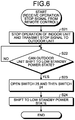
- FIG. 6 is a flowchart illustrating an example of the operation for shifting the outdoor unit 2 of the air conditioner 100 from the operating state to the low standby power state.
- the operation illustrated in FIG. 6 commences when the indoor unit 1a or 1b receives an operation stop signal from the remote control 3 while the air conditioner 100 is in operation.
- the remote control 3 transmits the operation stop signal, for example, when receiving a user's manipulation for stopping the operation.
- the indoor unit 1a or 1b Upon receiving the operation stop signal, the indoor unit 1a or 1b stops an air conditioning operation and transmits a stop signal to the outdoor unit 2 (step S21).
- the air conditioning operation is an operation directly related to air conditioning such as an air blowing operation or a wind direction adjustment operation, and does not include, for example, an operation in which the communication circuit 13 communicates with the outdoor unit 2, or an operation in which the remote control signal receiving unit 17 receives a signal from the remote control 3.
- the indoor unit controller 11 stops the air conditioning operation and further generates and transmits the stop signal to the outdoor unit 2 via the communication circuit 13.
- the outdoor unit 2 checks whether or not the outdoor unit 2 can shift to the low standby power state (step S22).
- the outdoor unit controller 37 determines whether or not the outdoor unit 2 can shift to the low standby power state.
- the outdoor unit controller 37 determines that the outdoor unit can shift to the low standby power state when a certain condition is satisfied.
- the outdoor unit controller 37 determines whether or not the outdoor unit can shift to the low standby power state.
- the outdoor unit controller 37 considers the outdoor unit as being shiftable to the low standby power state, when the outdoor unit controller 37 determines, on the basis of the prediction of the change in the outside air temperature and the compressor temperature, that a preheating operation of the compressor 32 is not required as the air conditioning operation of all the indoor units 1a and 1b stops.
- the preheating operation of the compressor 32 is an operation of adjusting the temperature of the compressor 32 by allowing the coil of the motor of the compressor 32 to generate heat with a current flowing therethrough.
- step S22 If the outdoor unit 2 is unable to shift to the low standby power state (No in step S22), the outdoor unit 2 repeats the checking processing until the outdoor unit 2 becomes shiftable to the low standby power state. If the outdoor unit 2 can shift to the low standby power state (Yes in step S22), the outdoor unit 2 opens the switches 24 and 25 in reverse order to the recovery from the low standby power state. That is, the outdoor unit controller 37 first opens the switch 25 and then opens the switch 24 (step S23). As a result, the outdoor unit 2 shifts to the low standby power state (step S24).
- the air conditioner 100 has the outdoor unit 2 and the indoor units 1a and 1b connected to each other through four connecting cables.
- a first connecting cable and a second connecting cable are used for supply of power from the outdoor unit 2 to the indoor units 1a and 1b.
- a fourth connecting cable is used such that the indoor units 1a and 1b operate the switches for starting the outdoor unit 2.
- the outdoor unit 2 communicate with the indoor units 1a and 1b.
- the function of reducing power consumption during standby can be achieved at low cost. Because noise generated when operating the switch does not flow to the connecting cable for communication, the communication quality between the outdoor unit 2 and the indoor units 1a and 1b does not deteriorate due to the noise and the cable for communication can be extended.
- FIG. 7 is a diagram illustrating another example of the configuration of an air conditioner according to an embodiment of the present invention.
- An air conditioner 100a illustrated in FIG. 7 is the air conditioner 100 illustrated in FIG. 1 with the outdoor unit 2 replaced with an outdoor unit 2a.
- the outdoor unit 2a is the outdoor unit 2 with a switch 39 and an inrush current preventing element 40 added.
- the switch 39 and the inrush current preventing element 40 are connected in series, and are provided between the terminal S1 and the terminal S4 of the wiring connector 38. Specifically, one end of the switch 39 is connected to the terminal S4, and an opposite end of the switch 39 is connected to one end of the inrush current preventing element 40. An opposite end of the inrush current preventing element 40 is connected to the terminal S1.
- the switch 39 is a fourth switch of the outdoor unit 2a. Since the configuration of the outdoor unit 2a is similar to that of the outdoor unit 2 except for the switch 39 and the inrush current preventing element 40, the description of the similar configuration is omitted.
- the outdoor unit 2a can use the switch 39 to notify the indoor unit 1a of a shift of the outdoor unit 2 to the low standby power state.
- the outdoor unit controller 37 starts the operation to close the switches 24 and 25, and subsequently closes the switch 39.
- the outdoor unit controller 37 opens the switch 39 as well as the switches 24 and 25.
- the indoor unit 1a may use the detection circuit 14 for identifying the state of the switch 39 so as to detect that the outdoor unit 2a has shifted to the low standby power state.
Landscapes
- Engineering & Computer Science (AREA)
- Chemical & Material Sciences (AREA)
- Combustion & Propulsion (AREA)
- Mechanical Engineering (AREA)
- General Engineering & Computer Science (AREA)
- Air Conditioning Control Device (AREA)
Abstract
Description
- The present invention relates to an air conditioner that includes a function of reducing power consumption during standby.
-
Patent Literature 1 describes a conventional air conditioner that can reduce power consumption during standby. For the air conditioner described inPatent Literature 1, an outdoor unit includes a switch for interrupting power supplied from a commercial power supply to the outdoor unit, so that no power is supplied from the commercial power supply to the outdoor unit during standby. When the outdoor unit is to start, the switch of the outdoor unit is controlled by an indoor unit so that the power is supplied to the outdoor unit. At this time, a switch within the indoor unit has changed its connection state such that a current passes through a coil in the switch of the outdoor unit to thereby close the switch. - Patent Literature 1: Japanese Patent Application Laid-open No.
2014-152968 - In the air conditioner described in
Patent Literature 1, the indoor unit supplies the power for starting the outdoor unit, using a communication signal line provided for communication with the outdoor unit. Changing the connection state of the switch of the indoor unit determines whether the communication signal line is used for the purpose of communicating with the outdoor unit or for the purpose of supplying the power to the outdoor unit. The outdoor unit has a communication circuit always connected to the communication signal line. For this reason, an excessive voltage may be applied to the communication circuit of the outdoor unit when the connection state of the switch of the indoor unit is changed. It has thus been necessary to take measures to prevent the circuit from failing due to the application of such an excessive voltage. Specifically, measures such as adding a resistance element for limiting the current and using a high-voltage component have been required. - The present invention has been made in view of the above, and an object of the present invention is to provide an air conditioner that can reduce the number of components used for measures against circuit failure.
- In order to solve the above problem and achieve the object, the present invention provides an air conditioner comprising an indoor unit and an outdoor unit. The outdoor unit includes: a first connection terminal, a second connection terminal, a third connection terminal, and a fourth connection terminal that are connected to the indoor unit; a power converter; and a switch assembly provided between the first connection terminal and the power converter. The indoor unit includes: first, second, third, and fourth indoor unit terminals, the first indoor unit terminal being connected to the first connection terminal, the second indoor unit terminal being connected to the second connection terminal, the third indoor unit terminal being connected to the third connection terminal, and the fourth indoor unit terminal being connected to the fourth connection terminal; and a switch provided between the first indoor unit terminal and the fourth indoor unit terminal. The switch assembly includes: a first switch that is closed when receiving power supply from the second connection terminal and the fourth connection terminal; and a second switch connected in parallel with the first switch. AC power is applied to the first connection terminal and the second connection terminal, and the outdoor unit and the indoor unit communicate through a connecting cable that interconnects the third connection terminal and the third indoor unit terminal. The indoor unit closes the switch when receiving a start signal in a low standby power state that is a state in which the operation of the power converter stops, and the indoor unit opening the switch after the operation of the power converter starts, and the outdoor unit closes the second switch when the first switch is closed to start supply of AC power to the power converter.
- The air conditioner according to the present invention has an effect of reducing the number of the components used for measures against the circuit failure.
-
-
FIG. 1 is a diagram illustrating an example of the configuration of an air conditioner according to an embodiment of the present invention. -
FIG. 2 is a diagram illustrating an example of the configuration of a detection circuit of an indoor unit. -
FIG. 3 is a diagram illustrating another example of the configuration of the detection circuit of the indoor unit. -
FIG. 4 is a diagram illustrating hardware that implements an indoor unit controller of the indoor unit. -
FIG. 5 is a flowchart illustrating an example of an operation for recovery of an outdoor unit from a low standby power state. -
FIG. 6 is a flowchart illustrating an example of an operation for shifting the outdoor unit from an operating state to the low standby power state. -
FIG. 7 is a diagram illustrating another example of the configuration of an air conditioner according to an embodiment of the present invention. - An air conditioner according to an embodiment of the present invention will now be described in detail with reference to the drawings. Note that the present invention is not limited to the embodiment.
-
FIG. 1 is a diagram illustrating an example of the configuration of an air conditioner according to an embodiment of the present invention. Anair conditioner 100 according to the embodiment includesindoor units outdoor unit 2. Theair conditioner 100 may include one or more indoor units althoughFIG. 1 illustrates theair conditioner 100 as including the two indoor units. Moreover, although an example in which the configuration of theindoor unit 1a is different from the configuration of theindoor unit 1b will be described, a plurality of the indoor units may all have the same configuration. That is, theair conditioner 100 may include a plurality of theindoor units 1a and a singleoutdoor unit 2, or a plurality of theindoor units 1b and a singleoutdoor unit 2. Theoutdoor unit 2 is connected to anAC power supply 60 through abreaker 61. - The
indoor unit 1a includes anindoor unit controller 11, apower supply circuit 12, acommunication circuit 13, adetection circuit 14, aswitch 15, awiring connector 16, a remote controlsignal receiving unit 17, arectifier circuit 18, and an inrushcurrent preventing element 19. - The
indoor unit controller 11 controls each of elements that make up theindoor unit 1a. The elements to be controlled by theindoor unit controller 11 include theswitch 15. Thepower supply circuit 12 generates control power supply for operating theindoor unit controller 11 and thecommunication circuit 13. Thecommunication circuit 13 is a circuit for theindoor unit 1a to communicate with theoutdoor unit 2. - The
switch 15 is provided for starting theoutdoor unit 2. Theswitch 15 is closed when starting theoutdoor unit 2 and is opened in other situations. That is, in theair conditioner 100 according to the present embodiment, the starting power is supplied from theindoor unit 1a to theoutdoor unit 2 when theswitch 15 is closed. - The
detection circuit 14 is a circuit for detecting that theswitch 15 is operated. Thedetection circuit 14 can have a path configured as illustrated inFIG. 2 or 3 . For thedetection circuit 14 configured as illustrated inFIG. 2 , a detector acquires a pulse waveform after half-wave rectification. That is, the detector detects the pulse waveform when theswitch 15 is closed. For thedetection circuit 14 configured as illustrated inFIG. 3 , the sensor acquires a DC voltage after full-wave rectification. That is, the detector detects a non-zero DC voltage when theswitch 15 is closed. Although thedetection circuit 14 is not essential and thus can be omitted, providing theindoor unit controller 11 with thedetection circuit 14 allows theindoor unit controller 11 to identify whether or not theswitch 15 is operated normally under the control of theindoor unit controller 11. - The
wiring connector 16 includes terminals S1 to S4 for interconnecting cables that electrically connect theindoor unit 1a and theoutdoor unit 2 to each other. Theswitch 15 described above is provided between the terminal S1 and the terminal S4 of thewiring connector 16, and is controlled by theindoor unit controller 11 such that theswitch 15 short-circuits the terminal S1 and the terminal S4 in starting theoutdoor unit 2. Moreover, thecommunication circuit 13 described above is connected to the terminal S2 and the terminal S3 of thewiring connector 16. Here, the terminal S1 is a first indoor unit terminal, the terminal S2 is a second indoor unit terminal, the terminal S3 is a third indoor unit terminal, and the terminal S4 is a fourth indoor unit terminal. The remote controlsignal receiving unit 17 is a circuit for receiving a signal transmitted from aremote control 3. Therectifier circuit 18 converts, into DC power, AC power supplied from theAC power supply 60 via theoutdoor unit 2. - The inrush current preventing
element 19 is a resistor and is connected in series to theswitch 15. Specifically, the inrush current preventingelement 19 has its one end connected to theswitch 15, and an opposite end connected to the terminal S1 of thewiring connector 16. The inrush current preventingelement 19 is provided to suppress an inrush current flowing in the circuit when theswitch 15 is closed. - The
indoor unit 1b has a configuration that does not include thedetection circuit 14 of theindoor unit 1a, and each component of theindoor unit 1b is designated by the same reference numeral as the corresponding component of theindoor unit 1a. For this reason, description of the details of theindoor unit 1b is omitted. - The
outdoor unit 2 includes apower supply connector 21, afilter circuit 22, switches 23 to 25, an inrush current preventingelement 26, arectifier circuit 28, abooster circuit 29, aninverter circuit 30, acompressor 32, atemperature sensor 33, acommunication circuit 34, a powersupply generation unit 35, an outdoor unitwaveform generation unit 36, an outdoor unit controller 37, and awiring connector 38. Theswitches 23 to 25 and the inrush current preventingelement 26 make up aswitch assembly 27 that opens and closes a power supply path to therectifier circuit 28. Therectifier circuit 28, thebooster circuit 29, and theinverter circuit 30 form apower converter 31 that generates drive power for thecompressor 32. Theswitch 23 is a first switch, theswitch 24 is a second switch, and theswitch 25 is a third switch. - The
power supply connector 21 includes two terminals L and N that are connected to theAC power supply 60. The terminal L is a first power supply terminal, and the terminal N is a second power supply terminal. Thefilter circuit 22 removes a noise component propagating through a power line that interconnects theAC power supply 60 and theoutdoor unit 2. Note that thefilter circuit 22 may be omitted when the noise component propagating through the power line is small, that is, when the noise component is at a level that does not adversely affect the operation of theair conditioner 100 and the operation of another device connected to theAC power supply 60. - The
switches 23 to 25 are provided for reducing power consumption of theoutdoor unit 2 during standby. Theswitches 23 to 25 are connected in parallel. One end of each of theswitches 23 to 25 is connected to the terminal L of thepower supply connector 21 via thefilter circuit 22. An opposite end of each of theswitches element 26 defined by a resistor. An opposite end of the inrush current preventingelement 26 and an opposite end of theswitch 25 are connected to one of two input terminals of therectifier circuit 28. An initial state of theswitches 23 to 25 is an opened state. Here, theswitch 25 is a mechanical switch in which a contact is closed by magnetic force generated by an internal coil when a current passes through the coil upon receiving AC power. Theswitches FIG. 1 , theswitch unit 27, which is made up of theswitches 23 to 25 and the inrush current preventingelement 26, is disposed on the power supply path on the side of the terminal L, but theswitch unit 27 may be disposed on the power supply path on the side of the terminal N. - The
rectifier circuit 28 converts, into DC power, AC power supplied from theAC power supply 60 and outputs the DC power. Therectifier circuit 28 has its output side connected to thebooster circuit 29. Thebooster circuit 29 has its output side connected to theinverter circuit 30 and the powersupply generation unit 35. - The
booster circuit 29 boosts the DC power output from therectifier circuit 28, and supplies the boosted DC power to theinverter circuit 30 and the powersupply generation unit 35. Theinverter circuit 30 has its output side connected to thecompressor 32. Theinverter circuit 30 converts the DC voltage input from thebooster circuit 29, into AC and generates the drive power for thecompressor 32. Note that thebooster circuit 29 is not essential and can be omitted. - The
compressor 32 includes a motor (not shown) to drive the motor with the power supplied from theinverter circuit 30 and compress a refrigerant flowing through refrigerant piping (not shown). Thetemperature sensor 33 detects the temperature of thecompressor 32. - The
communication circuit 34 communicates with thecommunication circuits 13 of theindoor units supply generation unit 35 converts the DC voltage input from thebooster circuit 29 and generates control power supply for operating the outdoor unitwaveform generation unit 36 and the outdoor unit controller 37. The powersupply generation unit 35 also generates control power supply for operating thecommunication circuit 33. The outdoor unitwaveform generation unit 36 generates a pulse width modulation (PWM) signal for controlling switching elements of theinverter circuit 30. The outdoor unit controller 37 controls theswitches - The
wiring connector 38 includes the terminals S1 to S4. These terminals S1 to S4 are connected to cables for electrically connecting theoutdoor unit 2 and theindoor units wiring connector 38 is a first connection terminal, and is connected to the terminal S1 of thewiring connector 16 of each of theindoor units wiring connector 38 is a second connection terminal, and is connected to the terminal S2 of thewiring connector 16 of each of theindoor units wiring connector 38 is a third connection terminal, and is connected to the terminal S3 of thewiring connector 16 of each of theindoor units wiring connector 38 is a fourth connection terminal, and is connected to the terminal S4 of thewiring connector 16 of each of theindoor units wiring connector 38 is connected to the terminal L of thepower supply connector 21, and the terminal S2 of thewiring connector 38 is connected to the terminal N of thepower supply connector 21. Therefore, the AC power from theAC power supply 60 is applied to the terminals S1 and S2. The AC power supplied from theAC power supply 60 to theoutdoor unit 2 is supplied to theindoor units wiring connector 38. Thecommunication circuit 34 is connected to the terminals S2 and S3 of thewiring connector 38. Moreover, an internal coil of theswitch 23 is connected between the terminal S2 and the terminal S4 of thewiring connector 38. - Hardware for implementing the
indoor unit controller 11 of each of theindoor units FIG. 1 will be described. Theindoor unit controller 11 of each of theindoor units control circuit 200 illustrated inFIG. 4 , specifically, aprocessor 201 and amemory 202. - The
processor 201 is a central processing unit (CPU), which is also referred to as a central processor, a processing unit, an arithmetic unit, a microprocessor, a microcomputer, a processor, or a digital signal processor (DSP). Thememory 202 includes, for example, a nonvolatile or volatile semiconductor memory such as a random access memory (RAM), a read only memory (ROM), a flash memory, an erasable programmable read only memory (EPROM), or an electrically erasable programmable read only memory (EEPROM (registered trademark)), or a magnetic disk. - The
indoor unit controller 11 is implemented by thememory 202 holding a program in which processing executed by theindoor unit controller 11 is described, and theprocessor 201 reading and executing the program. Note that theindoor unit controller 11 may be implemented by a processing circuit as dedicated hardware. In this case, the processing circuit corresponds to a single circuit, a complex circuit, a programmed processor, a parallel-programmed processor, an application specific integrated circuit (ASIC), a field programmable gate array (FPGA), or a combination of those. - The outdoor unit
waveform generation unit 36 and the outdoor unit controller 37 of theoutdoor unit 2 illustrated inFIG. 1 can also be implemented by hardware similar to that of theindoor unit controller 11. - For the
air conditioner 100 according to the present embodiment illustrated inFIG. 1 , theswitches outdoor unit 2 are opened when the operation of the air conditioner stops, such that theoutdoor unit 2 shifts to a low standby power state. The low standby power state refers to a state in which the operation of thepower converter 31 stops without power being supplied to therectifier circuit 28 of theoutdoor unit 2, such that power consumption is kept low. For theair conditioner 100, also, theswitch 15 of theindoor unit 1a is closed when theoutdoor unit 2 is in the low standby power state, such that theoutdoor unit 2 recovers from the low standby power state. - Next, a description will be made as to operations of the air conditioner 100: an operation for starting the
outdoor unit 2, that is, an operation for recovery of theoutdoor unit 2 from the low standby power state; and an operation for shifting theoutdoor unit 2 from the operating state to the low standby power state. - First, the operation when the
outdoor unit 2 recovers from the low standby power state will be described with reference toFIG. 5. FIG. 5 is a flowchart illustrating an example of the operation for recovery of theoutdoor unit 2 of theair conditioner 100 from the low standby power state. - The operation illustrated in
FIG. 5 commences when thebreaker 61 connected to theoutdoor unit 2 is turned on and power is supplied from theAC power supply 60 to theoutdoor unit 2. - Once the
breaker 61 is turned on, supply of power from theAC power supply 60 to theindoor units AC power supply 60 to theindoor units power supply connector 21 and the terminals S1 and S2 of thewiring connector 38 of theoutdoor unit 2. Upon the start of supply of power to theindoor units rectifier circuits 18 convert alternating current into direct current, and thepower supply circuits 12 generate control power supply and supply the power supply to theindoor unit controllers 11 and thecommunication circuits 13. When theindoor units indoor unit controllers 11 and thecommunication circuits 13 receiving the power supply from the power supply circuits 12 (step S11), theair conditioner 100 enters a standby state. Note that theswitches outdoor unit 2 are still opened at the time thebreaker 61 is turned on; as a result, power is not supplied to therectifier circuit 28 of theoutdoor unit 2. That is, theoutdoor unit 2 is in the low standby power state. - The
indoor units remote control 3 after starting the operations (step S12). The start signal here is a signal that instructs theair conditioner 100 to start. Theremote control 3 transmits the start signal, for example, when receiving a user's manipulation for starting the operation. - The
indoor units indoor units signal receiving units 17 receive the signal transmitted from theremote control 3, and theindoor unit controllers 11 determine whether or not the signal received by the remote controlsignal receiving units 17 is the start signal. - If having received the start signal (Yes in step S12), the
indoor units switch 23 of the outdoor unit 2 (step S14). That is, when theswitches 15 are closed, the terminals S1 and S4 of thewiring connectors 16 are short-circuited. This allows a current to pass through the coil inside theswitch 23 of theoutdoor unit 2, so that the contact of theswitch 23 is operated to close theswitch 23. Theindoor unit controllers 11 perform the operation of closing theswitches 15. - When the
switch 23 is closed, the power from theAC power supply 60 is supplied to therectifier circuit 28 via theswitch 23 and the inrush current preventingelement 26. Then, the power converted into direct current by therectifier circuit 28 is supplied to theinverter circuit 30 and the powersupply generation unit 35 via thebooster circuit 29. As a result, the powersupply generation unit 35 starts generating the control power supply, and the outdoor unitwaveform generation unit 36, the outdoor unit controller 37, and thecommunication circuit 34 start the operation upon receiving the control power supply generated by the powersupply generation unit 35. - Upon starting the operation, the outdoor unit controller 37 first closes the
switch 24 and then closes the switch 25 (step S15). The reason for operating theswitches switch 24 first allows the inrush current preventingelement 26 connected in series with theswitch 24 to suppress the inrush current flowing into therectifier circuit 28 at the start of power supply. When theswitch 25 is closed thereafter, the power is supplied to therectifier circuit 28 without passing through the inrush current preventingelement 26, thereby preventing wasteful consumption of power from taking place at the inrush current preventingelement 26. - The outdoor unit controller 37 also generates a signal indicating that the
power converter 31 has started its operation to thereby start theoutdoor unit 2, and transmits the signal to theindoor units communication circuit 34. - The signal indicating that the
outdoor unit 2 has started is received by thecommunication circuits 13 of theindoor units indoor unit controllers 11. Upon receiving the signal indicating that theoutdoor unit 2 has started, theindoor unit controllers 11 open theswitches 15. Note that among theindoor unit controllers 11 of theindoor units indoor unit controller 11 having closed theswitch 15 in response to the reception of the start signal from theremote control 3 opens theswitch 15. The otherindoor unit controller 11 does nothing even when receiving the signal indicating that theoutdoor unit 2 has started. When theswitch 15 is opened, the terminals S1 and S4 of thewiring connector 16 are brought out of the short-circuited state. As a result, the current no longer passes through the coil inside theswitch 23 of theoutdoor unit 2, whereby theswitch 23 is opened. - Although the description has been made as to the case where the
outdoor unit 2 in the low standby power state recovers by theindoor unit outdoor unit 2 may also recover from the low standby power state when a certain period of time (such as 30 minutes) has elapsed since the shift to the low standby power state. - Next, the operation for shifting the
outdoor unit 2 from the operating state to the low standby power state will be described with reference toFIG. 6. FIG. 6 is a flowchart illustrating an example of the operation for shifting theoutdoor unit 2 of theair conditioner 100 from the operating state to the low standby power state. - The operation illustrated in
FIG. 6 commences when theindoor unit remote control 3 while theair conditioner 100 is in operation. Note that theremote control 3 transmits the operation stop signal, for example, when receiving a user's manipulation for stopping the operation. - Upon receiving the operation stop signal, the
indoor unit communication circuit 13 communicates with theoutdoor unit 2, or an operation in which the remote controlsignal receiving unit 17 receives a signal from theremote control 3. In theindoor unit signal receiving unit 17 receives the operation stop signal, theindoor unit controller 11 stops the air conditioning operation and further generates and transmits the stop signal to theoutdoor unit 2 via thecommunication circuit 13. - When receiving the stop signal transmitted from the
indoor unit outdoor unit 2 checks whether or not theoutdoor unit 2 can shift to the low standby power state (step S22). The outdoor unit controller 37 determines whether or not theoutdoor unit 2 can shift to the low standby power state. The outdoor unit controller 37 determines that the outdoor unit can shift to the low standby power state when a certain condition is satisfied. On the basis of, for example, the state of theindoor units temperature sensor 33 of theoutdoor unit 2, the outdoor unit controller 37 determines whether or not the outdoor unit can shift to the low standby power state. Specifically, the outdoor unit controller 37 considers the outdoor unit as being shiftable to the low standby power state, when the outdoor unit controller 37 determines, on the basis of the prediction of the change in the outside air temperature and the compressor temperature, that a preheating operation of thecompressor 32 is not required as the air conditioning operation of all theindoor units compressor 32 is an operation of adjusting the temperature of thecompressor 32 by allowing the coil of the motor of thecompressor 32 to generate heat with a current flowing therethrough. - If the
outdoor unit 2 is unable to shift to the low standby power state (No in step S22), theoutdoor unit 2 repeats the checking processing until theoutdoor unit 2 becomes shiftable to the low standby power state. If theoutdoor unit 2 can shift to the low standby power state (Yes in step S22), theoutdoor unit 2 opens theswitches switch 25 and then opens the switch 24 (step S23). As a result, theoutdoor unit 2 shifts to the low standby power state (step S24). - Thus, the
air conditioner 100 according to the present embodiment has theoutdoor unit 2 and theindoor units outdoor unit 2 to theindoor units indoor units outdoor unit 2. Moreover, via a third connecting cable, theoutdoor unit 2 communicate with theindoor units outdoor unit 2 and theindoor units - Note that the outdoor unit of the air conditioner configured as illustrated in
FIG. 7 provides a similar effect.FIG. 7 is a diagram illustrating another example of the configuration of an air conditioner according to an embodiment of the present invention. - An
air conditioner 100a illustrated inFIG. 7 is theair conditioner 100 illustrated inFIG. 1 with theoutdoor unit 2 replaced with anoutdoor unit 2a. Theoutdoor unit 2a is theoutdoor unit 2 with aswitch 39 and an inrush current preventingelement 40 added. Theswitch 39 and the inrush current preventingelement 40 are connected in series, and are provided between the terminal S1 and the terminal S4 of thewiring connector 38. Specifically, one end of theswitch 39 is connected to the terminal S4, and an opposite end of theswitch 39 is connected to one end of the inrush current preventingelement 40. An opposite end of the inrush current preventingelement 40 is connected to the terminal S1. Theswitch 39 is a fourth switch of theoutdoor unit 2a. Since the configuration of theoutdoor unit 2a is similar to that of theoutdoor unit 2 except for theswitch 39 and the inrush current preventingelement 40, the description of the similar configuration is omitted. - In the
air conditioner 100a, theoutdoor unit 2a can use theswitch 39 to notify theindoor unit 1a of a shift of theoutdoor unit 2 to the low standby power state. For example, the outdoor unit controller 37 starts the operation to close theswitches switch 39. In shifting to the low standby power state, the outdoor unit controller 37 opens theswitch 39 as well as theswitches indoor unit 1a may use thedetection circuit 14 for identifying the state of theswitch 39 so as to detect that theoutdoor unit 2a has shifted to the low standby power state. - The configuration illustrated in the above embodiment merely illustrates an example of the content of the present invention, and can thus be combined with another known technique or partially omitted and/or modified without departing from the scope of the present invention.
- 1a, 1b indoor unit; 2, 2a outdoor unit; 3 remote control; 11 indoor unit controller; 12 power supply circuit; 13, 34 communication circuit; 14 detection circuit; 15, 23, 24, 25, 39 switch; 16, 38 wiring connector; 17 remote control signal receiving unit; 27 switch assembly; 18, 28 rectifier circuit; 19, 26, 40 inrush current preventing element; 21 power supply connector; 22 filter circuit; 29 booster circuit; 30 inverter circuit; 31 power converter; 32 compressor; 33 temperature sensor; 35 power supply generation unit; 36 outdoor unit waveform generation unit; 37 outdoor unit controller; 60 AC power supply; 61 breaker; 100, 100a air conditioner.
Claims (7)
- An air conditioner comprising an indoor unit and an outdoor unit, wherein
the outdoor unit includes:a first connection terminal, a second connection terminal, a third connection terminal, and a fourth connection terminal that are connected to the indoor unit;a power converter; anda switch assembly provided between the first connection terminal and the power converter,the indoor unit includes: first, second, third, and fourth indoor unit terminals, the first indoor unit terminal being connected to the first connection terminal, the second indoor unit terminal being connected to the second connection terminal, the third indoor unit terminal being connected to the third connection terminal, and the fourth indoor unit terminal being connected to the fourth connection terminal; anda switch provided between the first indoor unit terminal and the fourth indoor unit terminal,the switch assembly includes:a first switch that is closed when receiving power supply from the second connection terminal and the fourth connection terminal; anda second switch connected in parallel with the first switch,AC power is applied to the first connection terminal and the second connection terminal,the outdoor unit and the indoor unit communicate through a connecting cable that interconnects the third connection terminal and the third indoor unit terminal,the indoor unit closes the switch when receiving a start signal in a low standby power state that is a state in which the operation of the power converter stops, and the indoor unit opening the switch after the operation of the power converter starts, andthe outdoor unit closes the second switch when the first switch is closed to start supply of AC power to the power converter. - The air conditioner according to claim 1, wherein
the outdoor unit closes the second switch that is opened, and then transmits, to the indoor unit, a signal indicating that the operation of the power converter starts, and
the indoor unit opens the switch of the indoor unit upon receiving the signal indicating that the operation of the power converter starts. - The air conditioner according to claim 1 or 2, wherein
the outdoor unit opens the second switch and shifts to the low standby power state when a certain condition is satisfied. - The air conditioner according to any one of claims 1 to 3, wherein
the switch includes:an inrush current preventing element having one end connected to the first switch and the second switch, and an opposite end connected to the power converter; anda third switch connected in parallel with the first switch, the second switch, and the inrush current preventing element, andthe outdoor unitcloses the third switch after closing the second switch. - The air conditioner according to claim 4, wherein
the outdoor unit
opens the third switch first and then opens the second switch, when opening the second switch. - The air conditioner according to any one of claims 1 to 5, wherein
the outdoor unit:includes a fourth switch provided between the first connection terminal and the fourth connection terminal; andnotifies the indoor unit of a shift of the outdoor unit to the low standby power state by switching between a state of the fourth switch when the outdoor unit is in the low standby power state and a state of the fourth switch when the outdoor unit is not in the low standby power state. - The air conditioner according to any one of claims 1 to 6, wherein the indoor unit is plural in number, the plurality of the indoor units is connected to the outdoor unit.
Applications Claiming Priority (1)
| Application Number | Priority Date | Filing Date | Title |
|---|---|---|---|
| PCT/JP2017/027086 WO2019021397A1 (en) | 2017-07-26 | 2017-07-26 | Air conditioner |
Publications (3)
| Publication Number | Publication Date |
|---|---|
| EP3660406A1 true EP3660406A1 (en) | 2020-06-03 |
| EP3660406A4 EP3660406A4 (en) | 2020-08-12 |
| EP3660406B1 EP3660406B1 (en) | 2023-05-24 |
Family
ID=65040066
Family Applications (1)
| Application Number | Title | Priority Date | Filing Date |
|---|---|---|---|
| EP17918831.3A Active EP3660406B1 (en) | 2017-07-26 | 2017-07-26 | Air conditioner |
Country Status (6)
| Country | Link |
|---|---|
| US (1) | US11486596B2 (en) |
| EP (1) | EP3660406B1 (en) |
| JP (1) | JP6732132B2 (en) |
| CN (1) | CN110959092B (en) |
| AU (1) | AU2017424871B2 (en) |
| WO (1) | WO2019021397A1 (en) |
Cited By (2)
| Publication number | Priority date | Publication date | Assignee | Title |
|---|---|---|---|---|
| US11162700B2 (en) * | 2017-11-16 | 2021-11-02 | Qingdao Haier Air Conditioner General Corp., Ltd. | Method and apparatus for identifying air-conditioning circuit, and air conditioner |
| EP3944484A1 (en) * | 2020-07-24 | 2022-01-26 | Guangdong Giwee Technology Co., Ltd. | Communication circuit for indoor and outdoor units of air conditioner and air conditioner |
Families Citing this family (3)
| Publication number | Priority date | Publication date | Assignee | Title |
|---|---|---|---|---|
| CN110173871B (en) * | 2019-05-10 | 2022-04-15 | 广东美的制冷设备有限公司 | Communication control method and device of air conditioner and air conditioner |
| JP7598014B2 (en) * | 2021-03-10 | 2024-12-11 | ダイキン工業株式会社 | Refrigeration System |
| CN114811861B (en) * | 2022-03-30 | 2023-11-24 | 青岛海尔空调电子有限公司 | Central air conditioner control method and central air conditioner |
Family Cites Families (17)
| Publication number | Priority date | Publication date | Assignee | Title |
|---|---|---|---|---|
| JP3730808B2 (en) * | 1999-06-03 | 2006-01-05 | 株式会社日立製作所 | Air conditioner |
| JP2004190889A (en) * | 2002-12-09 | 2004-07-08 | Sharp Corp | Air conditioner |
| JP3806882B2 (en) * | 2004-11-29 | 2006-08-09 | ダイキン工業株式会社 | Air conditioner |
| KR20080035173A (en) * | 2006-10-18 | 2008-04-23 | 삼성전자주식회사 | Air Conditioner and Control Method |
| JP2010121810A (en) * | 2008-11-18 | 2010-06-03 | Panasonic Corp | Communication control device for air conditioner |
| JP5241585B2 (en) * | 2009-04-06 | 2013-07-17 | 三菱電機株式会社 | Air conditioner |
| KR101706102B1 (en) * | 2010-02-12 | 2017-02-27 | 삼성전자주식회사 | Air conditioner |
| KR101858938B1 (en) * | 2011-09-19 | 2018-06-29 | 삼성전자주식회사 | Air conditioner |
| AU2012359736B2 (en) * | 2011-12-28 | 2014-11-13 | Daikin Industries, Ltd. | Air conditioner |
| JP5772588B2 (en) * | 2011-12-28 | 2015-09-02 | ダイキン工業株式会社 | Air conditioner |
| JP2014152968A (en) | 2013-02-06 | 2014-08-25 | Mitsubishi Electric Corp | Air conditioner |
| JP5648700B2 (en) * | 2013-02-08 | 2015-01-07 | ダイキン工業株式会社 | Power consumption reduction device |
| JP5984732B2 (en) * | 2013-04-09 | 2016-09-06 | 三菱電機株式会社 | Air conditioner |
| JP5549775B2 (en) * | 2013-10-24 | 2014-07-16 | ダイキン工業株式会社 | Air conditioner |
| JP6157374B2 (en) * | 2014-02-05 | 2017-07-05 | 三菱電機株式会社 | Air conditioner |
| JP6184391B2 (en) * | 2014-11-07 | 2017-08-23 | 三菱電機株式会社 | Air conditioner |
| CN106440220B (en) * | 2016-10-12 | 2019-07-02 | 青岛海尔空调器有限总公司 | Air conditioner standby circuit and air conditioner |
-
2017
- 2017-07-26 EP EP17918831.3A patent/EP3660406B1/en active Active
- 2017-07-26 WO PCT/JP2017/027086 patent/WO2019021397A1/en not_active Ceased
- 2017-07-26 US US16/616,676 patent/US11486596B2/en active Active
- 2017-07-26 JP JP2019532272A patent/JP6732132B2/en not_active Expired - Fee Related
- 2017-07-26 CN CN201780093379.7A patent/CN110959092B/en not_active Expired - Fee Related
- 2017-07-26 AU AU2017424871A patent/AU2017424871B2/en not_active Ceased
Cited By (2)
| Publication number | Priority date | Publication date | Assignee | Title |
|---|---|---|---|---|
| US11162700B2 (en) * | 2017-11-16 | 2021-11-02 | Qingdao Haier Air Conditioner General Corp., Ltd. | Method and apparatus for identifying air-conditioning circuit, and air conditioner |
| EP3944484A1 (en) * | 2020-07-24 | 2022-01-26 | Guangdong Giwee Technology Co., Ltd. | Communication circuit for indoor and outdoor units of air conditioner and air conditioner |
Also Published As
| Publication number | Publication date |
|---|---|
| WO2019021397A1 (en) | 2019-01-31 |
| AU2017424871B2 (en) | 2021-01-14 |
| CN110959092A (en) | 2020-04-03 |
| JP6732132B2 (en) | 2020-07-29 |
| US20200200419A1 (en) | 2020-06-25 |
| EP3660406A4 (en) | 2020-08-12 |
| EP3660406B1 (en) | 2023-05-24 |
| CN110959092B (en) | 2021-03-12 |
| AU2017424871A1 (en) | 2020-01-02 |
| US11486596B2 (en) | 2022-11-01 |
| JPWO2019021397A1 (en) | 2019-11-07 |
Similar Documents
| Publication | Publication Date | Title |
|---|---|---|
| EP3660406B1 (en) | Air conditioner | |
| JP6184391B2 (en) | Air conditioner | |
| US4695738A (en) | Energy management system | |
| US9581626B2 (en) | Circuit and method for detecting zero-crossings and brownout conditions on a single phase or multi-phase system | |
| US10418915B2 (en) | Refrigeration cycle apparatus | |
| CN111226364A (en) | Power supply device, power control device, and relay determination method for power supply device | |
| JP6797311B2 (en) | Air conditioner | |
| US10742023B2 (en) | Air conditioner | |
| KR101928829B1 (en) | Light system having an uninterruptible power supply | |
| US10944350B2 (en) | Motor drive device | |
| EP3367559B1 (en) | Air conditioner | |
| JP5804009B2 (en) | Air conditioner | |
| US7529106B2 (en) | Voltage monitoring device and inverter device | |
| US10072666B2 (en) | Hermetic compressor driving device | |
| TW201735538A (en) | Electronic switch device and electronic switch system | |
| JP2018105557A (en) | Air conditioner | |
| JP2015055450A (en) | Air conditioner | |
| JP2006109670A (en) | Three-phase phase loss detection circuit | |
| JP4623221B2 (en) | Power circuit | |
| WO2021131394A1 (en) | Welding detector and welding detection method | |
| JP7854616B2 (en) | Switching device | |
| US20250168983A1 (en) | Circuit board | |
| JP5874029B2 (en) | Two-wire load control device | |
| JP2024171539A (en) | Switching device | |
| CN116829882A (en) | air conditioning unit |
Legal Events
| Date | Code | Title | Description |
|---|---|---|---|
| STAA | Information on the status of an ep patent application or granted ep patent |
Free format text: STATUS: THE INTERNATIONAL PUBLICATION HAS BEEN MADE |
|
| PUAI | Public reference made under article 153(3) epc to a published international application that has entered the european phase |
Free format text: ORIGINAL CODE: 0009012 |
|
| STAA | Information on the status of an ep patent application or granted ep patent |
Free format text: STATUS: REQUEST FOR EXAMINATION WAS MADE |
|
| 17P | Request for examination filed |
Effective date: 20200116 |
|
| AK | Designated contracting states |
Kind code of ref document: A1 Designated state(s): AL AT BE BG CH CY CZ DE DK EE ES FI FR GB GR HR HU IE IS IT LI LT LU LV MC MK MT NL NO PL PT RO RS SE SI SK SM TR |
|
| AX | Request for extension of the european patent |
Extension state: BA ME |
|
| A4 | Supplementary search report drawn up and despatched |
Effective date: 20200710 |
|
| RIC1 | Information provided on ipc code assigned before grant |
Ipc: H02H 3/00 20060101ALI20200706BHEP Ipc: F24F 1/0003 20190101ALI20200706BHEP Ipc: F24F 11/88 20180101ALI20200706BHEP Ipc: H02M 7/00 20060101ALI20200706BHEP Ipc: F24F 11/46 20180101ALN20200706BHEP Ipc: H02M 3/00 20060101AFI20200706BHEP |
|
| DAV | Request for validation of the european patent (deleted) | ||
| DAX | Request for extension of the european patent (deleted) | ||
| REG | Reference to a national code |
Ref country code: DE Ref legal event code: R079 Ref document number: 602017069126 Country of ref document: DE Free format text: PREVIOUS MAIN CLASS: F24F0001020000 Ipc: H02M0003158000 |
|
| GRAP | Despatch of communication of intention to grant a patent |
Free format text: ORIGINAL CODE: EPIDOSNIGR1 |
|
| STAA | Information on the status of an ep patent application or granted ep patent |
Free format text: STATUS: GRANT OF PATENT IS INTENDED |
|
| RIC1 | Information provided on ipc code assigned before grant |
Ipc: F24F 11/46 20180101ALN20221118BHEP Ipc: H02M 1/36 20070101ALI20221118BHEP Ipc: F24F 1/0003 20190101ALI20221118BHEP Ipc: F24F 11/88 20180101ALI20221118BHEP Ipc: H02H 3/00 20060101ALI20221118BHEP Ipc: H02M 7/06 20060101ALI20221118BHEP Ipc: H02M 3/158 20060101AFI20221118BHEP |
|
| INTG | Intention to grant announced |
Effective date: 20221207 |
|
| GRAS | Grant fee paid |
Free format text: ORIGINAL CODE: EPIDOSNIGR3 |
|
| GRAA | (expected) grant |
Free format text: ORIGINAL CODE: 0009210 |
|
| STAA | Information on the status of an ep patent application or granted ep patent |
Free format text: STATUS: THE PATENT HAS BEEN GRANTED |
|
| AK | Designated contracting states |
Kind code of ref document: B1 Designated state(s): AL AT BE BG CH CY CZ DE DK EE ES FI FR GB GR HR HU IE IS IT LI LT LU LV MC MK MT NL NO PL PT RO RS SE SI SK SM TR |
|
| REG | Reference to a national code |
Ref country code: GB Ref legal event code: FG4D |
|
| REG | Reference to a national code |
Ref country code: CH Ref legal event code: EP |
|
| REG | Reference to a national code |
Ref country code: DE Ref legal event code: R096 Ref document number: 602017069126 Country of ref document: DE |
|
| P01 | Opt-out of the competence of the unified patent court (upc) registered |
Effective date: 20230508 |
|
| REG | Reference to a national code |
Ref country code: AT Ref legal event code: REF Ref document number: 1570169 Country of ref document: AT Kind code of ref document: T Effective date: 20230615 |
|
| REG | Reference to a national code |
Ref country code: IE Ref legal event code: FG4D |
|
| REG | Reference to a national code |
Ref country code: LT Ref legal event code: MG9D |
|
| REG | Reference to a national code |
Ref country code: NL Ref legal event code: MP Effective date: 20230524 |
|
| REG | Reference to a national code |
Ref country code: AT Ref legal event code: MK05 Ref document number: 1570169 Country of ref document: AT Kind code of ref document: T Effective date: 20230524 |
|
| PG25 | Lapsed in a contracting state [announced via postgrant information from national office to epo] |
Ref country code: SE Free format text: LAPSE BECAUSE OF FAILURE TO SUBMIT A TRANSLATION OF THE DESCRIPTION OR TO PAY THE FEE WITHIN THE PRESCRIBED TIME-LIMIT Effective date: 20230524 Ref country code: PT Free format text: LAPSE BECAUSE OF FAILURE TO SUBMIT A TRANSLATION OF THE DESCRIPTION OR TO PAY THE FEE WITHIN THE PRESCRIBED TIME-LIMIT Effective date: 20230925 Ref country code: NO Free format text: LAPSE BECAUSE OF FAILURE TO SUBMIT A TRANSLATION OF THE DESCRIPTION OR TO PAY THE FEE WITHIN THE PRESCRIBED TIME-LIMIT Effective date: 20230824 Ref country code: NL Free format text: LAPSE BECAUSE OF FAILURE TO SUBMIT A TRANSLATION OF THE DESCRIPTION OR TO PAY THE FEE WITHIN THE PRESCRIBED TIME-LIMIT Effective date: 20230524 Ref country code: ES Free format text: LAPSE BECAUSE OF FAILURE TO SUBMIT A TRANSLATION OF THE DESCRIPTION OR TO PAY THE FEE WITHIN THE PRESCRIBED TIME-LIMIT Effective date: 20230524 Ref country code: AT Free format text: LAPSE BECAUSE OF FAILURE TO SUBMIT A TRANSLATION OF THE DESCRIPTION OR TO PAY THE FEE WITHIN THE PRESCRIBED TIME-LIMIT Effective date: 20230524 |
|
| PG25 | Lapsed in a contracting state [announced via postgrant information from national office to epo] |
Ref country code: RS Free format text: LAPSE BECAUSE OF FAILURE TO SUBMIT A TRANSLATION OF THE DESCRIPTION OR TO PAY THE FEE WITHIN THE PRESCRIBED TIME-LIMIT Effective date: 20230524 Ref country code: PL Free format text: LAPSE BECAUSE OF FAILURE TO SUBMIT A TRANSLATION OF THE DESCRIPTION OR TO PAY THE FEE WITHIN THE PRESCRIBED TIME-LIMIT Effective date: 20230524 Ref country code: LV Free format text: LAPSE BECAUSE OF FAILURE TO SUBMIT A TRANSLATION OF THE DESCRIPTION OR TO PAY THE FEE WITHIN THE PRESCRIBED TIME-LIMIT Effective date: 20230524 Ref country code: LT Free format text: LAPSE BECAUSE OF FAILURE TO SUBMIT A TRANSLATION OF THE DESCRIPTION OR TO PAY THE FEE WITHIN THE PRESCRIBED TIME-LIMIT Effective date: 20230524 Ref country code: IS Free format text: LAPSE BECAUSE OF FAILURE TO SUBMIT A TRANSLATION OF THE DESCRIPTION OR TO PAY THE FEE WITHIN THE PRESCRIBED TIME-LIMIT Effective date: 20230924 Ref country code: HR Free format text: LAPSE BECAUSE OF FAILURE TO SUBMIT A TRANSLATION OF THE DESCRIPTION OR TO PAY THE FEE WITHIN THE PRESCRIBED TIME-LIMIT Effective date: 20230524 Ref country code: GR Free format text: LAPSE BECAUSE OF FAILURE TO SUBMIT A TRANSLATION OF THE DESCRIPTION OR TO PAY THE FEE WITHIN THE PRESCRIBED TIME-LIMIT Effective date: 20230825 |
|
| PG25 | Lapsed in a contracting state [announced via postgrant information from national office to epo] |
Ref country code: FI Free format text: LAPSE BECAUSE OF FAILURE TO SUBMIT A TRANSLATION OF THE DESCRIPTION OR TO PAY THE FEE WITHIN THE PRESCRIBED TIME-LIMIT Effective date: 20230524 |
|
| PG25 | Lapsed in a contracting state [announced via postgrant information from national office to epo] |
Ref country code: SK Free format text: LAPSE BECAUSE OF FAILURE TO SUBMIT A TRANSLATION OF THE DESCRIPTION OR TO PAY THE FEE WITHIN THE PRESCRIBED TIME-LIMIT Effective date: 20230524 |
|
| PG25 | Lapsed in a contracting state [announced via postgrant information from national office to epo] |
Ref country code: SM Free format text: LAPSE BECAUSE OF FAILURE TO SUBMIT A TRANSLATION OF THE DESCRIPTION OR TO PAY THE FEE WITHIN THE PRESCRIBED TIME-LIMIT Effective date: 20230524 Ref country code: SK Free format text: LAPSE BECAUSE OF FAILURE TO SUBMIT A TRANSLATION OF THE DESCRIPTION OR TO PAY THE FEE WITHIN THE PRESCRIBED TIME-LIMIT Effective date: 20230524 Ref country code: RO Free format text: LAPSE BECAUSE OF FAILURE TO SUBMIT A TRANSLATION OF THE DESCRIPTION OR TO PAY THE FEE WITHIN THE PRESCRIBED TIME-LIMIT Effective date: 20230524 Ref country code: EE Free format text: LAPSE BECAUSE OF FAILURE TO SUBMIT A TRANSLATION OF THE DESCRIPTION OR TO PAY THE FEE WITHIN THE PRESCRIBED TIME-LIMIT Effective date: 20230524 Ref country code: DK Free format text: LAPSE BECAUSE OF FAILURE TO SUBMIT A TRANSLATION OF THE DESCRIPTION OR TO PAY THE FEE WITHIN THE PRESCRIBED TIME-LIMIT Effective date: 20230524 Ref country code: CZ Free format text: LAPSE BECAUSE OF FAILURE TO SUBMIT A TRANSLATION OF THE DESCRIPTION OR TO PAY THE FEE WITHIN THE PRESCRIBED TIME-LIMIT Effective date: 20230524 |
|
| REG | Reference to a national code |
Ref country code: DE Ref legal event code: R097 Ref document number: 602017069126 Country of ref document: DE |
|
| PG25 | Lapsed in a contracting state [announced via postgrant information from national office to epo] |
Ref country code: MC Free format text: LAPSE BECAUSE OF FAILURE TO SUBMIT A TRANSLATION OF THE DESCRIPTION OR TO PAY THE FEE WITHIN THE PRESCRIBED TIME-LIMIT Effective date: 20230524 |
|
| PG25 | Lapsed in a contracting state [announced via postgrant information from national office to epo] |
Ref country code: MC Free format text: LAPSE BECAUSE OF FAILURE TO SUBMIT A TRANSLATION OF THE DESCRIPTION OR TO PAY THE FEE WITHIN THE PRESCRIBED TIME-LIMIT Effective date: 20230524 |
|
| REG | Reference to a national code |
Ref country code: CH Ref legal event code: PL |
|
| REG | Reference to a national code |
Ref country code: BE Ref legal event code: MM Effective date: 20230731 |
|
| PG25 | Lapsed in a contracting state [announced via postgrant information from national office to epo] |
Ref country code: LU Free format text: LAPSE BECAUSE OF NON-PAYMENT OF DUE FEES Effective date: 20230726 |
|
| PG25 | Lapsed in a contracting state [announced via postgrant information from national office to epo] |
Ref country code: LU Free format text: LAPSE BECAUSE OF NON-PAYMENT OF DUE FEES Effective date: 20230726 |
|
| PLBE | No opposition filed within time limit |
Free format text: ORIGINAL CODE: 0009261 |
|
| STAA | Information on the status of an ep patent application or granted ep patent |
Free format text: STATUS: NO OPPOSITION FILED WITHIN TIME LIMIT |
|
| REG | Reference to a national code |
Ref country code: IE Ref legal event code: MM4A |
|
| PG25 | Lapsed in a contracting state [announced via postgrant information from national office to epo] |
Ref country code: CH Free format text: LAPSE BECAUSE OF NON-PAYMENT OF DUE FEES Effective date: 20230731 |
|
| 26N | No opposition filed |
Effective date: 20240227 |
|
| PG25 | Lapsed in a contracting state [announced via postgrant information from national office to epo] |
Ref country code: SI Free format text: LAPSE BECAUSE OF FAILURE TO SUBMIT A TRANSLATION OF THE DESCRIPTION OR TO PAY THE FEE WITHIN THE PRESCRIBED TIME-LIMIT Effective date: 20230524 |
|
| PG25 | Lapsed in a contracting state [announced via postgrant information from national office to epo] |
Ref country code: SI Free format text: LAPSE BECAUSE OF FAILURE TO SUBMIT A TRANSLATION OF THE DESCRIPTION OR TO PAY THE FEE WITHIN THE PRESCRIBED TIME-LIMIT Effective date: 20230524 Ref country code: IT Free format text: LAPSE BECAUSE OF FAILURE TO SUBMIT A TRANSLATION OF THE DESCRIPTION OR TO PAY THE FEE WITHIN THE PRESCRIBED TIME-LIMIT Effective date: 20230524 Ref country code: FR Free format text: LAPSE BECAUSE OF NON-PAYMENT OF DUE FEES Effective date: 20230731 Ref country code: BE Free format text: LAPSE BECAUSE OF NON-PAYMENT OF DUE FEES Effective date: 20230731 |
|
| PG25 | Lapsed in a contracting state [announced via postgrant information from national office to epo] |
Ref country code: IE Free format text: LAPSE BECAUSE OF NON-PAYMENT OF DUE FEES Effective date: 20230726 |
|
| PGFP | Annual fee paid to national office [announced via postgrant information from national office to epo] |
Ref country code: GB Payment date: 20240606 Year of fee payment: 8 |
|
| PG25 | Lapsed in a contracting state [announced via postgrant information from national office to epo] |
Ref country code: IE Free format text: LAPSE BECAUSE OF NON-PAYMENT OF DUE FEES Effective date: 20230726 |
|
| PG25 | Lapsed in a contracting state [announced via postgrant information from national office to epo] |
Ref country code: BG Free format text: LAPSE BECAUSE OF FAILURE TO SUBMIT A TRANSLATION OF THE DESCRIPTION OR TO PAY THE FEE WITHIN THE PRESCRIBED TIME-LIMIT Effective date: 20230524 |
|
| PG25 | Lapsed in a contracting state [announced via postgrant information from national office to epo] |
Ref country code: BG Free format text: LAPSE BECAUSE OF FAILURE TO SUBMIT A TRANSLATION OF THE DESCRIPTION OR TO PAY THE FEE WITHIN THE PRESCRIBED TIME-LIMIT Effective date: 20230524 |
|
| PG25 | Lapsed in a contracting state [announced via postgrant information from national office to epo] |
Ref country code: CY Free format text: LAPSE BECAUSE OF FAILURE TO SUBMIT A TRANSLATION OF THE DESCRIPTION OR TO PAY THE FEE WITHIN THE PRESCRIBED TIME-LIMIT; INVALID AB INITIO Effective date: 20170726 |
|
| PG25 | Lapsed in a contracting state [announced via postgrant information from national office to epo] |
Ref country code: HU Free format text: LAPSE BECAUSE OF FAILURE TO SUBMIT A TRANSLATION OF THE DESCRIPTION OR TO PAY THE FEE WITHIN THE PRESCRIBED TIME-LIMIT; INVALID AB INITIO Effective date: 20170726 |
|
| PGFP | Annual fee paid to national office [announced via postgrant information from national office to epo] |
Ref country code: DE Payment date: 20250604 Year of fee payment: 9 |
|
| PG25 | Lapsed in a contracting state [announced via postgrant information from national office to epo] |
Ref country code: TR Free format text: LAPSE BECAUSE OF FAILURE TO SUBMIT A TRANSLATION OF THE DESCRIPTION OR TO PAY THE FEE WITHIN THE PRESCRIBED TIME-LIMIT Effective date: 20230524 |
|
| GBPC | Gb: european patent ceased through non-payment of renewal fee |
Effective date: 20250726 |
|
| PG25 | Lapsed in a contracting state [announced via postgrant information from national office to epo] |
Ref country code: GB Free format text: LAPSE BECAUSE OF NON-PAYMENT OF DUE FEES Effective date: 20250726 |