EP3660314B1 - Screw compressor and refrigeration device - Google Patents
Screw compressor and refrigeration device Download PDFInfo
- Publication number
- EP3660314B1 EP3660314B1 EP18918417.9A EP18918417A EP3660314B1 EP 3660314 B1 EP3660314 B1 EP 3660314B1 EP 18918417 A EP18918417 A EP 18918417A EP 3660314 B1 EP3660314 B1 EP 3660314B1
- Authority
- EP
- European Patent Office
- Prior art keywords
- screw compressor
- movable portion
- liquid supply
- refrigerant
- valve
- Prior art date
- Legal status (The legal status is an assumption and is not a legal conclusion. Google has not performed a legal analysis and makes no representation as to the accuracy of the status listed.)
- Active
Links
- 238000005057 refrigeration Methods 0.000 title claims description 42
- 239000007788 liquid Substances 0.000 claims description 184
- 239000003507 refrigerant Substances 0.000 claims description 92
- 238000001514 detection method Methods 0.000 claims description 15
- 230000002093 peripheral effect Effects 0.000 claims description 5
- 238000002347 injection Methods 0.000 description 36
- 239000007924 injection Substances 0.000 description 36
- 230000007423 decrease Effects 0.000 description 13
- 230000000694 effects Effects 0.000 description 13
- 238000001816 cooling Methods 0.000 description 10
- 230000015556 catabolic process Effects 0.000 description 6
- 238000006731 degradation reaction Methods 0.000 description 6
- 238000010586 diagram Methods 0.000 description 6
- 230000006835 compression Effects 0.000 description 5
- 238000007906 compression Methods 0.000 description 5
- 230000003247 decreasing effect Effects 0.000 description 2
- 238000007599 discharging Methods 0.000 description 2
- 238000000926 separation method Methods 0.000 description 2
- 230000000593 degrading effect Effects 0.000 description 1
- 239000000463 material Substances 0.000 description 1
- 238000005192 partition Methods 0.000 description 1
- 230000000149 penetrating effect Effects 0.000 description 1
- 239000000243 solution Substances 0.000 description 1
Images


Classifications
-
- F—MECHANICAL ENGINEERING; LIGHTING; HEATING; WEAPONS; BLASTING
- F04—POSITIVE - DISPLACEMENT MACHINES FOR LIQUIDS; PUMPS FOR LIQUIDS OR ELASTIC FLUIDS
- F04C—ROTARY-PISTON, OR OSCILLATING-PISTON, POSITIVE-DISPLACEMENT MACHINES FOR LIQUIDS; ROTARY-PISTON, OR OSCILLATING-PISTON, POSITIVE-DISPLACEMENT PUMPS
- F04C18/00—Rotary-piston pumps specially adapted for elastic fluids
- F04C18/08—Rotary-piston pumps specially adapted for elastic fluids of intermeshing-engagement type, i.e. with engagement of co-operating members similar to that of toothed gearing
- F04C18/12—Rotary-piston pumps specially adapted for elastic fluids of intermeshing-engagement type, i.e. with engagement of co-operating members similar to that of toothed gearing of other than internal-axis type
- F04C18/14—Rotary-piston pumps specially adapted for elastic fluids of intermeshing-engagement type, i.e. with engagement of co-operating members similar to that of toothed gearing of other than internal-axis type with toothed rotary pistons
- F04C18/16—Rotary-piston pumps specially adapted for elastic fluids of intermeshing-engagement type, i.e. with engagement of co-operating members similar to that of toothed gearing of other than internal-axis type with toothed rotary pistons with helical teeth, e.g. chevron-shaped, screw type
-
- F—MECHANICAL ENGINEERING; LIGHTING; HEATING; WEAPONS; BLASTING
- F04—POSITIVE - DISPLACEMENT MACHINES FOR LIQUIDS; PUMPS FOR LIQUIDS OR ELASTIC FLUIDS
- F04C—ROTARY-PISTON, OR OSCILLATING-PISTON, POSITIVE-DISPLACEMENT MACHINES FOR LIQUIDS; ROTARY-PISTON, OR OSCILLATING-PISTON, POSITIVE-DISPLACEMENT PUMPS
- F04C29/00—Component parts, details or accessories of pumps or pumping installations, not provided for in groups F04C18/00 - F04C28/00
- F04C29/12—Arrangements for admission or discharge of the working fluid, e.g. constructional features of the inlet or outlet
-
- F—MECHANICAL ENGINEERING; LIGHTING; HEATING; WEAPONS; BLASTING
- F04—POSITIVE - DISPLACEMENT MACHINES FOR LIQUIDS; PUMPS FOR LIQUIDS OR ELASTIC FLUIDS
- F04C—ROTARY-PISTON, OR OSCILLATING-PISTON, POSITIVE-DISPLACEMENT MACHINES FOR LIQUIDS; ROTARY-PISTON, OR OSCILLATING-PISTON, POSITIVE-DISPLACEMENT PUMPS
- F04C28/00—Control of, monitoring of, or safety arrangements for, pumps or pumping installations specially adapted for elastic fluids
- F04C28/10—Control of, monitoring of, or safety arrangements for, pumps or pumping installations specially adapted for elastic fluids characterised by changing the positions of the inlet or outlet openings with respect to the working chamber
- F04C28/12—Control of, monitoring of, or safety arrangements for, pumps or pumping installations specially adapted for elastic fluids characterised by changing the positions of the inlet or outlet openings with respect to the working chamber using sliding valves
-
- F—MECHANICAL ENGINEERING; LIGHTING; HEATING; WEAPONS; BLASTING
- F04—POSITIVE - DISPLACEMENT MACHINES FOR LIQUIDS; PUMPS FOR LIQUIDS OR ELASTIC FLUIDS
- F04C—ROTARY-PISTON, OR OSCILLATING-PISTON, POSITIVE-DISPLACEMENT MACHINES FOR LIQUIDS; ROTARY-PISTON, OR OSCILLATING-PISTON, POSITIVE-DISPLACEMENT PUMPS
- F04C29/00—Component parts, details or accessories of pumps or pumping installations, not provided for in groups F04C18/00 - F04C28/00
- F04C29/0007—Injection of a fluid in the working chamber for sealing, cooling and lubricating
- F04C29/0014—Injection of a fluid in the working chamber for sealing, cooling and lubricating with control systems for the injection of the fluid
Definitions
- the present disclosure relates to a screw compressor and a refrigeration device including the screw compressor.
- a liquid injection mechanism which injects a refrigerant liquid liquefied by a condenser from a hole disposed in a casing to a compression space and controls the temperature of a refrigerant gas discharged from the screw compressor.
- Patent Documents 1 and 2 each disclose a screw compressor having the above liquid injection mechanism. Examples of compressors for a refrigeration device are disclosed in JP S57 38692 , US 4025244 and WO 2018/037469 .
- a liquid injection mechanism is used to decrease a discharge temperature
- a refrigerant liquid evaporates by removing heat of a compressed gas under compression, bringing a disadvantage that an extra work to compress the evaporated gas to a discharge pressure is needed.
- a liquid can be injected at a position close to a position where the discharge pressure is obtained.
- an injection position of the refrigerant liquid in a screw compressor is fixed.
- the liquid injection port is connected to a discharge portion, disabling liquid injection if an internal volume ratio (Vi) adjusting valve moves to a low internal volume ratio side (suction side), or a pressure of a compression space adjacent to the injection port is decreased, and thus may result in the refrigerant liquid being injected excessively if the internal volume ratio (Vi) adjusting valve moves to a high internal volume ratio side (discharge side) to handle a situation where a suction pressure decreases. Consequently, the temperature of a discharge gas may become unstable, degrading performance and reliability of the screw compressor.
- a liquid supply amount of a flow-rate adjusting valve instantly increases upon a decrease in the pressure of the compression space adjacent to the liquid injection port.
- a liquid may excessively be supplied.
- the unloader slide valve moves to the suction side, the liquid injection port is connected to the discharge portion, which may produce undesirable phenomenons such as an increase in compression power, a rise in internal pressure, an increase in bearing load, and an increase in compressor vibration. Consequently, problems such as an unstable discharge temperature, and degradation in performance and a decrease in life of the compressor may arise.
- An object of an embodiment is to improve a coefficient of performance (COP) and to improve reliability of the compressor by enabling stable control of the temperature of the refrigerant gas discharged from a screw compressor having a liquid injection function even if operating conditions change in the screw compressor.
- COP coefficient of performance
- a screw compressor disclosed herein includes a rotor casing, a pair of screw rotors disposed in the rotor casing and engaging with each other, and a movable portion disposed so as to be movable in a rotor shaft direction of the pair of screw rotors.
- the movable portion includes liquefied liquid supply ports capable of supplying a liquefied liquid of a compressed gas toward tooth groove spaces formed by the pair of screw rotors, wherein the screw compressor further comprises a position sensor configured to detect a position of the movable portion in the rotor shaft direction; a flow-rate adjusting valve configured to adjust an amount of the liquified liquid to be supplied and a controller configured to control an opening degree of the flow-rate adjusting valve based on a detection value of the position sensor.
- the tooth groove spaces are a plurality of enclosed spaces formed between a pair of male and female screw rotors engaging with each other inside the rotor casing, and gradually decrease in volume as the tooth groove spaces move to a discharge side. Consequently, a refrigerant gas in the tooth groove spaces is increased in pressure and discharged from a discharge port.
- the above-described liquefied liquid supply ports can move in the rotor shaft direction with the movable portion, it is possible to stably control the temperature of the refrigerant gas discharged from the screw compressor (to be also referred to as a "discharge gas temperature" hereinafter) by adjusting positions of the liquefied liquid supply ports in the rotor shaft direction even if operating conditions change.
- the movable portion is provided with the liquefied liquid supply ports, it is possible to arrange the liquefied liquid supply ports such that they communicate with tooth groove spaces on a side which is close to the discharge port and has a high pressure.
- the movable portion internally forms a cavity, and the liquefied liquid supply ports communicate with the cavity and are formed by through holes opening to an outer peripheral surface of the movable portion.
- the movable portion includes an extending portion extending outside the rotor casing in the rotor shaft direction
- the screw compressor further includes a drive portion driving the movable portion via the extending portion in the rotor shaft direction
- the extending portion internally forms a liquefied liquid introduction space communicating with the cavity and linearly extending in the rotor shaft direction.
- the screw compressor further includes an internal volume ratio variable control valve capable of controlling an internal volume ratio of the compressed gas sucked into the rotor casing, and the movable portion is constituted by a valve body of the internal volume ratio variable control valve.
- the liquefied liquid supply ports are disposed on the valve body of the internal volume ratio variable control valve, making it possible to set the liquefied liquid supply ports at positions in the rotor shaft direction with the relatively high internal volume ratio having a less influence on compressor performance while the valve body is set with the optimum internal volume ratio depending on the operating conditions.
- the screw compressor further includes a volume control slide valve, and the movable portion is constituted by a valve body of the volume control slide valve.
- the liquefied liquid supply ports are formed in the valve body of the internal volume ratio variable control valve, making it possible to set the liquefied liquid supply ports at discharge-side positions having the less influence on the compressor performance in the rotor shaft direction while the valve body is set at an optimum position for volume control depending on the operating conditions.
- it is possible to stably control the discharge gas temperature while suppressing the degradation in the compressor performance and to improve the cooling effect of the compressed gas.
- the plurality of liquefied liquid supply ports are arranged in the rotor shaft direction.
- the plurality of liquefied liquid supply ports are arranged toward at least a pre-discharge tooth groove space and a tooth groove space adjacent to the pre-discharge tooth groove space of the plurality of tooth groove spaces formed by the pair of screw rotors.
- a refrigeration device disclosed herein includes a refrigerant circulation line, a refrigeration cycle constituting device including the screw compressor according to any one of the above configurations (1) to (7) and a condenser disposed on the refrigerant circulation line, and a refrigerant liquid supply line supplying a refrigerant liquid liquefied by the condenser to the movable portion.
- the refrigeration device since the refrigeration device includes the screw compressor having the above configuration, it is possible to stably control the discharge gas temperature and to arrange the liquefied liquid supply ports to the tooth groove spaces on the side which is close to the discharge port and has the high pressure even if the operating conditions change. Thus, it is possible to efficiently decrease the discharge gas temperature and to reduce the workload of the compressor as compared with the case in which the liquid is injected on the side close to the suction port.
- the movable portion is constituted by a valve body of an internal volume ratio variable control valve capable of controlling an internal volume ratio of a refrigerant gas sucked into the rotor casing
- the refrigeration device further includes a temperature sensor detecting a temperature of a refrigerant gas discharged from the screw compressor, a flow-rate adjusting valve disposed on the refrigerant liquid supply line, and a first controller controlling an opening degree of the flow-rate adjusting valve based on a detection value of the temperature sensor and controlling a temperature of the refrigerant gas discharged from the screw compressor.
- the first controller controls the opening degree of the flow-rate adjusting valve disposed on the refrigerant liquid supply line based on the detection value of the temperature sensor, it is possible to control the discharge gas temperature. Thus, it is possible to improve control accuracy of the discharge gas temperature.
- the movable portion is constituted by a valve body of an internal volume ratio variable control valve capable of controlling an internal volume ratio of a refrigerant gas sucked into the rotor casing
- the refrigeration device further includes a temperature sensor detecting a temperature of a refrigerant gas discharged from the screw compressor, a pressure sensor detecting a pressure of the refrigerant gas discharged from the screw compressor, a flow-rate adjustment valve disposed on the refrigerant liquid supply line, and a second controller controlling an opening degree of the flow-rate adjusting valve based on detection values of the temperature sensor and the pressure sensor, and controlling a degree of superheat of the refrigerant gas discharged from the screw compressor.
- the second controller controls the opening degree of the flow-rate adjusting valve disposed on the refrigerant liquid supply line based on the detection values of the temperature sensor and the pressure sensor, it is possible to accurately control the degree of superheat of the discharge gas.
- the controller responsible for the controlling of the opening degree of the flow-rate adjusting valve can detect the internal volume ratio and a volume control position depending on a position of the movable portion in the rotor shaft direction detected by the above-described position sensor. Then, the aforementioned controller controls the opening degree of the above-described flow-rate adjusting valve to set an optimum liquid injection amount for the detected internal volume ratio and the volume, making it possible to accurately control the discharge gas temperature and the degree of superheat.
- the refrigeration device further includes an oil separator separating oil from a refrigerant gas discharged from the screw compressor.
- the refrigeration device further includes a hermetic motor driving the screw compressor, and the refrigerant liquid supply line is introduced to the movable portion via the hermetic motor.
- the liquefied liquid supply ports since it is possible to arrange the liquefied liquid supply ports on a discharge side, it is possible to efficiently decrease the discharge gas temperature, to reduce a workload of the compressor, and to improve a COP as compared with a case in which a liquid is injected on a side close to a suction port.
- an expression of relative or absolute arrangement such as “in a direction”, “along a direction”, “parallel”, “orthogonal”, “centered”, “concentric” and “coaxial” shall not be construed as indicating only the arrangement in a strict literal sense, but also includes a state where the arrangement is relatively displaced by a tolerance, or by an angle or a distance whereby it is possible to achieve the same function.
- an expression of an equal state such as “same”, “equal”, and “uniform” shall not be construed as indicating only the state in which the feature is strictly equal, but also includes a state in which there is a tolerance or a difference that can still achieve the same function.
- an expression of a shape such as a rectangular shape or a cylindrical shape shall not be construed as only the geometrically strict shape, but also includes a shape with unevenness or chamfered corners within the range in which the same effect can be achieved.
- FIGS. 1 and 2 are vertical cross-sectional views of screw compressor 10 (10A, 10B) according to some embodiments.
- the screw compressor 10 houses a pair of screw rotors 14 engaging with each other inside a rotor casing 12.
- the pair of screw rotors 14 include a male rotor 14 (14a) and a female rotor 14 (14b).
- the pair of screw rotors 14 rotate in mutually opposite directions by, for example, forming a drive shaft 15 integrally with the male rotor on a discharge side and rotating the drive shaft 15 by a drive portion (not shown).
- a plurality of tooth groove spaces St are formed in a rotor shaft direction.
- the tooth groove spaces St communicate with a suction port 16 on an inlet side and communicate with a discharge port 18 on an outlet side.
- the tooth groove spaces St move to the discharge side in accordance with rotations of the screw rotors 14, and are shut off from the suction port 16 when the volume of the tooth groove spaces St becomes maximum.
- the ratio of the maximum suction volume to the volume of a tooth groove space immediately before communicating with the discharge port 18 will be referred to as an internal volume ratio (maximum suction volume/volume of pre-discharge tooth groove space) Vi.
- the screw compressor 10 includes a movable portion 20 disposed so as to be movable in the rotor shaft direction at a position adjacent to the pair of screw rotors 14.
- the movable portion 20 includes liquefied liquid supply ports 21 capable of supplying a liquefied liquid of a compressed gas toward the tooth groove spaces St.
- the liquefied liquid supply ports 21 can move in the rotor shaft direction with the movable portion 20, it is possible to stably control the temperature of a refrigerant gas discharged from the discharge port 18 by adjusting positions of the liquefied liquid supply ports 21 in the rotor shaft direction even if operating conditions change, and thus to improve reliability of the screw compressor 10.
- the movable portion 20 is provided with the liquefied liquid supply ports 21, it is possible to arrange the liquefied liquid supply ports 21 such that they communicate with the tooth groove spaces St on a side which is close to the discharge port 18 and has a high pressure.
- a plurality of liquefied liquid supply ports need to be disposed in the rotor shaft direction in order to change an injection position of a liquefied liquid according to a change in operating conditions. In this case, performance of the compressor 10 and the strength of the rotor casing 12 may be degraded.
- At least one of the liquefied liquid supply ports 21 is arranged to be positioned in a pre-discharge tooth groove space St 1 (see FIG. 3 ), making it possible to enhance the effect of decreasing the discharge gas temperature while suppressing degradation in compressor performance and to enhance the effect of reducing the workload of the screw compressor 10.
- a rotor shaft 22 of the pair of screw rotors 14 is rotatably supported by a radial bearing 24 and a thrust bearing 26 which are housed in a bearing head 13 disposed on the discharge side adjacent to the rotor casing 12.
- a balance piston 28 is disposed which corrects unbalance of opposite forces applied to the screw rotors 14 between the suction side and the discharge side.
- the drive shaft 15 is supported by a shaft seal device 30 and is led out of a casing 32.
- the movable portion 20 internally forms a cavity 34.
- the liquefied liquid supply ports 21 communicate with the cavity 34 and are formed by through holes opening to the outer peripheral surface of the movable portion 20.
- a supply passage for the liquefied liquid supplied to the liquefied liquid supply ports is formed inside the movable portion 20, it is possible to downsize the configuration of the refrigerant liquid supply passage.
- the liquefied liquid supply ports 21 are formed by the through holes opening to the outer peripheral surface of the movable portion 20, the liquefied liquid supply ports 21 are formed easily.
- the screw compressor 10 (10A) shown in FIG. 1 includes an internal volume ratio variable control valve 19 (19a) capable of controlling the internal volume ratio of the compressed gas sucked into the rotor casing 12.
- the variable control valve 19 (19a) can set the internal volume ratio Vi variable by changing a position in the rotor shaft direction.
- the movable portion 20 is constituted by a valve body of the variable control valve 19 (19a).
- an axial discharge port 36a is formed in the bearing head 13, and a radial discharge port 36b is formed at a discharge-side end of the variable control valve 19 (19a).
- the radial discharge port 36b restricts a discharge position of the compressed gas.
- variable control valve 19 since the existing variable control valve 19 is used as the movable portion 20, it is unnecessary to install an additional movable portion. Moreover, since the liquefied liquid supply ports 21 are disposed on the valve body of the variable control valve 19, it is possible to set the liquefied liquid supply ports 21 at positions in the rotor shaft direction with the relatively high internal volume ratio having a less influence on the compressor performance while the valve body of the variable control valve 19 is set with the optimum internal volume ratio Vi depending on the operating conditions. Thus, it is possible to stably control the discharge gas temperature while suppressing the degradation in the compressor performance and to improve the cooling effect of the compressed gas.
- the screw compressor 10 (10B) includes a volume control slide valve 19 (19b) capable of controlling a volume according to the load of the screw compressor 10 (10B).
- the movable portion 20 is constituted by the slide valve 19 (19b) .
- the liquefied liquid supply ports 21 are formed in a valve body of the slide valve 19 (19b), it is possible to set the liquefied liquid supply ports 21 at discharge-side positions having a less influence on the compressor performance in the rotor shaft direction while the valve body is set at an optimum position for volume control depending on the operating conditions. Thus, it is possible to stably control the discharge gas temperature while suppressing the degradation in the compressor performance and to improve the cooling effect of the compressed gas.
- the movable portion 20 includes an extending portion 38 which extends outside a casing 42 forming the rotor casing 12, the suction port 16, and the like in the rotor shaft direction.
- the movable portion 20 is driven by a drive portion 44 via the extending portion 38 in the rotor shaft direction, making it possible to adjust the positions of the movable portion 20 and the liquefied liquid supply ports 21 in the rotor shaft direction.
- the movable portion 20 and the extending portion 38 are formed integrally, and the extending portion 38 internally forms a liquefied liquid introduction space 40.
- the liquefied liquid introduction space 40 communicates with the cavity 34 and linearly extends in the rotor shaft direction. According to the present embodiment, since it is possible to introduce the liquefied liquid to the cavity 34 formed in the movable portion 20 via the liquefied liquid introduction space 40, it is possible to simplify the configuration of a liquefied liquid introduction path.
- variable control valve 19 (19a) is constituted by an internal volume ratio variable control valve which only controls the internal volume ratio Vi without making volume adjustment on the suction side. Accordingly, the volume of the screw compressor 10 is adjusted by causing the drive portion (not shown) of the pair of screw rotors 14 to control the rotation speed of the screw rotors 14. The internal volume ratio Vi is controlled by causing the drive portion 44 to move the movable portion 20 (the valve body of the variable control valve 19 (19a)) in the rotor shaft direction.
- a cylinder portion 48 is formed inside a casing 46 disposed to be connected to the casing 42, and the cylinder portion 48 includes a built-in hydraulic piston 50 disposed on the end part of the extending portion 38.
- the hydraulic piston 50 is driven in the rotor shaft direction by supplying/discharging pressurized oil to the cylinder portion 48 through pressurized oil supply/discharge passages 52. Supply/discharge of the pressurized oil is controlled by an electromagnetic valve 54.
- a connection pipe 56 is connected to the end part of the extending portion 38 from the outside of the casing 46, and a liquefied liquid Lr is supplied to the liquefied liquid introduction space 40 via the connection pipe 56.
- the slide valve 19 (19b) is constituted by a volume control slide valve having a variable function for the internal volume ratio Vi.
- the movable portion 20 and the extending portion 38 are formed independently of each other.
- the slide valve 19 (19b) controls the internal volume ratio Vi by causing the drive portion 44 having the same configuration as the embodiment shown in FIG. 1 to move the movable portion 20 (the valve body of the slide valve 19 (19b) in the rotor shaft direction.
- Volume control is performed by a drive portion 90 which is disposed in the casing 86 disposed adjacent to the casing 46. That is, the casing 86 internally forms a cylinder portion 88, and the cylinder portion 88 includes a built-in hydraulic piston 94.
- the hydraulic piston 94 is driven in the rotor shaft direction by supplying/discharging pressurized oil to the cylinder portion 88 through oil supply/discharge passages 96. Supply/discharge of the pressurized oil is controlled by an electromagnetic valve 98.
- the movable portion 20 thus moves in the rotor shaft direction independently of the extending portion 38, forming a gap between the movable portion 20 and the extending portion 38, and performing volume control.
- the liquefied liquid Lr is introduced to the cavity 34 through a connection pipe 41 disposed in the bearing head 13 in the rotor shaft direction.
- the end part of the connection pipe 41 is inserted in a through hole penetrating the cavity 34 of the movable portion 20 and a discharge-side surface of the movable portion 20.
- the other-end opening of the connection pipe 41 opens into the outside of the casing 32, and the liquefied liquid Lr is supplied from the opening.
- a seal and guide member 43 is disposed between the movable portion 20 and the connection pipe 41.
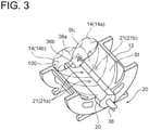
- FIG. 3 internally shows the rotor casing of the screw compressor 10 (10A) shown in FIG. 1 .
- the pair of male rotor 14 (14a) and female rotor 14 (14b) are arranged to engage with each other.
- the plurality of liquefied liquid supply ports 21 (21a) are formed in the movable portion 20 in the rotor shaft direction.
- the liquefied liquid is injected from a plurality of parts dispersed in the rotor shaft direction, it is possible to ensure a liquid supply amount needed to cool the compressed gas which is compressed and increased in temperature, and to uniformly cool the compressed gas in the rotor shaft direction.
- impact waves such as liquid hammers generated by injecting the liquefied liquid are dispersed, making it possible to mitigate an impact force thereof. It is also possible to maintain a liquid injection function even if some of the liquefied liquid supply ports 21 are clogged.
- the compressed gas contains refrigerator oil if the screw compressor 10 is incorporated in the refrigeration device.
- the plurality of liquefied liquid supply ports 21 (21a) are arranged toward at least the pre-discharge tooth groove space St 1 and the tooth groove space St adjacent to the pre-discharge tooth groove space St 1 of the plurality of tooth groove spaces St formed by the pair of screw rotors 14.
- the plurality of liquefied liquid supply ports 21 can each be formed by a through hole which has a transverse cross-section of a circular shape, an oval shape, or the like formed on a partition wall of the rotor casing 12 and opening into the inner surface of the rotor casing 12.
- the liquefied liquid supply ports 21 are formed easily.
- the liquefied liquid supply port 21 is formed by a through hole having a long hole transverse cross-section whose long sides are directed in the rotor shaft direction and opening into the inner surface of the rotor casing 12.
- the liquefied liquid supply port 21 (21b) can open over the two adjacent tooth groove spaces St when the plurality of tooth groove spaces St move in the rotor shaft direction, making it possible to perform the same liquid injection as in a case in which the through hole is formed in each tooth groove space of the plurality of tooth groove spaces St.
- a liquefied liquid supply port 100 shows an example of a conventional liquefied liquid supply port formed at a fixed site which is the end surface of the bearing head 13.
- the liquefied liquid supply port 100 is illustrated to be compared with the liquefied liquid supply ports 21 (21a, 21b) according to the embodiment.
- FIG. 3 shows the embodiment in which the screw compressor 10 (10A) with the variable control valve 19 (19a) includes the liquefied liquid supply ports 21 (21a, 21b), the screw compressor 10 (10B) with the slide valve 19 (19b) can also include the liquefied liquid supply ports 21 (21a, 21b).
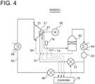
- a refrigeration device 60 (60A) according to an embodiment is configured to include, on a refrigerant circulation line 62, the screw compressor 10 having the above-described configuration and other refrigeration cycle constituting devices.
- the other refrigeration cycle constituting devices mainly include a condenser 64, an expansion valve 66, an evaporator 68, and the like.
- the drive shaft 15 of the screw compressor 10 is rotary driven by a drive portion 58.
- the refrigeration device 60 (60A) also includes a refrigerant liquid supply line 70 for supplying a refrigerant liquid liquefied by the condenser 64 to the movable portion 20 of the screw compressor 10. The refrigerant liquid is injected into the tooth groove spaces St from the liquefied liquid supply ports 21 formed in the movable portion 20.
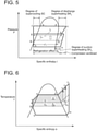
- FIG. 5 is a Mollier diagram of a refrigeration cycle constituted by the refrigeration device 60 according to an embodiment.
- FIG. 6 is a T-s diagram of the refrigeration cycle.
- a line L 0 is a line indicating conventional fixed refrigerant liquid injection performed at a position close to the suction side of the screw compressor 10
- a line L is a line indicating refrigerant liquid injection according to an embodiment in which the refrigerant liquid is injected from the movable portion 20.
- Reference symbol ⁇ i indicates a cooling effect of the refrigerant gas according to an embodiment
- reference symbol ⁇ i 0 indicates a conventional cooling effect of the refrigerant gas.
- a-c s -d-e-f-h-a represents a basic refrigeration cycle.
- a conventional refrigerant liquid injection cycle is represented by a refrigerant liquid injection line (b 0 -c 0 -d-e-f-g 0 -b 0 ) added to the above-described basic refrigeration cycle, and a discharge gas temperature c 0 is obtained.
- the refrigerant liquid injection cycle has an area A 0 which corresponds to a workload per unit of a liquid amount added to the basic refrigeration cycle.
- a position-variable refrigerant liquid injection cycle is represented by a refrigerant liquid injection line (b-c-d-e-f-g-b) added to the above-described basic refrigeration cycle, and a discharge gas temperature c is obtained.
- the refrigerant liquid injection cycle has an area A which corresponds to a workload per unit of a liquid amount added to the basic refrigeration cycle.
- a workload increased by liquid injection according to an embodiment is in the relation of the area A ⁇ a liquid injection amount G ⁇ the area A 0 ⁇ a liquid injection amount G 0 .
- the position-variable refrigerant liquid injection cycle since it is possible to inject the refrigerant liquid from a position having the higher internal volume ratio Vi than before, it is possible to cool the discharge gas to a temperature lower than before, and to reduce a wasteful workload (power) of the screw compressor 10 if the liquid supply amount is the same.
- a temperature sensor 74 detecting the temperature of the refrigerant gas discharged from the screw compressor 10 is provided on the discharge-side refrigerant circulation line 62 of the screw compressor 10.
- a flow-rate adjusting valve 72 is provided on the refrigerant liquid supply line 70.
- a detection value of the temperature sensor 74 is input to a controller 78.
- the controller 78 controls the opening degree of the flow-rate adjusting valve 72 based on the detection value.
- a refrigerant liquid tank 80 is provided downstream of the condenser 64 on the refrigerant circulation line 62, and the refrigerant liquid liquefied by the condenser 64 is sent downstream of the refrigerant circulation line 62 or the refrigerant liquid supply line 70 after once being stored in the refrigerant liquid tank 80.
- a pressure sensor 76 detecting the pressure of the refrigerant gas discharged from the screw compressor 10 is provided on the refrigerant circulation line 62 on the discharge side of the compressor.
- the controller 78 receives a detection value of the pressure sensor 76.
- the controller 78 calculates a degree of superheat SH of a compressor discharge gas based on the detection values of the temperature sensor 74 and the pressure sensor 76.
- the controller 78 controls the opening degree of the flow-rate adjusting valve 72 disposed on the refrigerant liquid supply line 70 so as to appropriately control the degree of superheat SH.
- the refrigeration device 60 (60A) further includes a position sensor 81 detecting the position of the movable portion (valve body) 20 in the rotor shaft direction.
- the controller 78 controls the opening degree of the flow-rate adjusting valve 72 based on a detection value of the position sensor 81.
- the controller 78 can obtain the internal volume ratio Vi depending on the position of the movable portion 20 in the rotor shaft direction detected by the position sensor 81. Then, the controller 78 can accurately control the discharge gas temperature and the degree of superheat SH by controlling the opening degree of the flow-rate adjusting valve 72 to set an optimum refrigerant liquid injection amount for the obtained internal volume ratio Vi.
- the outer surface of the extending portion 38 where the position sensor 81 is disposed forms an internal volume ratio position detection portion having a tapered surface oblique with respect to the rotor shaft direction.
- the position sensor 81 is arranged so as to contact the tapered surface.
- the position of the extending portion 38 in the rotor shaft direction is detected at a position of the position sensor 81 in a direction orthogonal to the rotor shaft direction.
- refrigerant liquid supply line 70 including the flow-rate adjusting valve 72 in place of the refrigerant liquid supply line 70 including the flow-rate adjusting valve 72, it is also possible to provide a first refrigerant liquid supply line including an orifice and a second refrigerant liquid supply line including an electromagnetic valve. Thus, it is possible to make a flow rate adjustment unit disposed on the refrigerant liquid supply line simple and less expensive.
- an oil separator 82 is provided on the refrigerant circulation line 62 on the discharge side of the screw compressor 10.
- the oil separator 82 separates oil from the refrigerant gas discharged from the screw compressor 10.
- the separated oil is returned to the screw compressor 10 from an oil circulation line 84 as refrigerator oil.
- the present embodiment since it is possible to inject the liquid on the side close to the discharge port 18 as described above by disposing the liquefied liquid supply ports 21 in the movable portion 20, it is possible to efficiently stabilize the discharge gas temperature at a low level. Thus, it is possible to decrease a steam pressure of oil entrained by the discharge gas, making it possible to improve separation performance of the oil separator 82 and to reduce the size of the oil separator 82.
- the oil separator 82 and the oil circulation line 84 are not installed in an embodiment in which the screw compressor 10 is not an oil-cooled compressor.
- the refrigeration device 60 (60B) shown in FIG. 7 includes a hermetic motor as the drive portion 58 driving the screw compressor 10.
- the refrigerant liquid supply line 70 is introduced to the movable portion 20 via the hermetic motor.
- the refrigerant liquid discharged from the flow-rate adjusting valve 72 is first introduced to the hermetic motor to cool the hermetic motor.
- an introducing path for the refrigerant liquid is introduced to the inside of a casing with an enclosed structure of the hermetic motor to enhance the cooling effect.
- the liquefied liquid after cooling the hermetic motor is sent to the movable portion 20 and injected into the tooth groove spaces St from the liquefied liquid supply ports 21.
- a screw compressor in a screw compressor, it is possible to stably control a discharge gas temperature by adjusting positions of liquefied liquid supply ports in a rotor shaft direction even if operating conditions change. It is also possible to efficiently decrease the discharge gas temperature, to reduce a workload of a compressor, and to improve a coefficient of performance of a refrigeration device in which the screw compressor is incorporated.
Landscapes
- Engineering & Computer Science (AREA)
- Mechanical Engineering (AREA)
- General Engineering & Computer Science (AREA)
- Applications Or Details Of Rotary Compressors (AREA)
Description
- The present disclosure relates to a screw compressor and a refrigeration device including the screw compressor.
- In a refrigeration device including a screw compressor and constituting a refrigeration cycle, a liquid injection mechanism is known which injects a refrigerant liquid liquefied by a condenser from a hole disposed in a casing to a compression space and controls the temperature of a refrigerant gas discharged from the screw compressor.
Patent Documents 1 and 2 each disclose a screw compressor having the above liquid injection mechanism. Examples of compressors for a refrigeration device are disclosed inJP S57 38692 US 4025244 andWO 2018/037469 . -
- Patent Document 1:
JPS63-025255B - Patent Document 2:
JPH03-079959A - Although a liquid injection mechanism is used to decrease a discharge temperature, a refrigerant liquid evaporates by removing heat of a compressed gas under compression, bringing a disadvantage that an extra work to compress the evaporated gas to a discharge pressure is needed. In order to reduce the disadvantage, a liquid can be injected at a position close to a position where the discharge pressure is obtained. However, in a conventional liquid injection mechanism, an injection position of the refrigerant liquid in a screw compressor is fixed. Therefore, in a case in which a liquid is injected with a conventional fixed liquid injection port, the liquid injection port is connected to a discharge portion, disabling liquid injection if an internal volume ratio (Vi) adjusting valve moves to a low internal volume ratio side (suction side), or a pressure of a compression space adjacent to the injection port is decreased, and thus may result in the refrigerant liquid being injected excessively if the internal volume ratio (Vi) adjusting valve moves to a high internal volume ratio side (discharge side) to handle a situation where a suction pressure decreases. Consequently, the temperature of a discharge gas may become unstable, degrading performance and reliability of the screw compressor.
- Moreover, in the case of a screw compressor incorporating an unloader slide valve and performing volume control, against a required liquid injection amount which decreases upon unload in the fixed liquid injection port, a liquid supply amount of a flow-rate adjusting valve instantly increases upon a decrease in the pressure of the compression space adjacent to the liquid injection port. As a result, a liquid may excessively be supplied. In addition, if the unloader slide valve moves to the suction side, the liquid injection port is connected to the discharge portion, which may produce undesirable phenomenons such as an increase in compression power, a rise in internal pressure, an increase in bearing load, and an increase in compressor vibration. Consequently, problems such as an unstable discharge temperature, and degradation in performance and a decrease in life of the compressor may arise.
- Furthermore, repeating such operations, durability of a liquid supply control valve disposed on a liquid injection line may be deteriorated.
- An object of an embodiment is to improve a coefficient of performance (COP) and to improve reliability of the compressor by enabling stable control of the temperature of the refrigerant gas discharged from a screw compressor having a liquid injection function even if operating conditions change in the screw compressor.
- According to the invention, there are provided the screw compressor and the refrigeration device as defined in the appended claims. (1) A screw compressor disclosed herein includes a rotor casing, a pair of screw rotors disposed in the rotor casing and engaging with each other, and a movable portion disposed so as to be movable in a rotor shaft direction of the pair of screw rotors. The movable portion includes liquefied liquid supply ports capable of supplying a liquefied liquid of a compressed gas toward tooth groove spaces formed by the pair of screw rotors, wherein the screw compressor further comprises a position sensor configured to detect a position of the movable portion in the rotor shaft direction; a flow-rate adjusting valve configured to adjust an amount of the liquified liquid to be supplied and a controller configured to control an opening degree of the flow-rate adjusting valve based on a detection value of the position sensor.
- The tooth groove spaces are a plurality of enclosed spaces formed between a pair of male and female screw rotors engaging with each other inside the rotor casing, and gradually decrease in volume as the tooth groove spaces move to a discharge side. Consequently, a refrigerant gas in the tooth groove spaces is increased in pressure and discharged from a discharge port.
- With the above configuration (1), since the above-described liquefied liquid supply ports can move in the rotor shaft direction with the movable portion, it is possible to stably control the temperature of the refrigerant gas discharged from the screw compressor (to be also referred to as a "discharge gas temperature" hereinafter) by adjusting positions of the liquefied liquid supply ports in the rotor shaft direction even if operating conditions change. In addition, since the movable portion is provided with the liquefied liquid supply ports, it is possible to arrange the liquefied liquid supply ports such that they communicate with tooth groove spaces on a side which is close to the discharge port and has a high pressure. Thus, it is possible to efficiently decrease the discharge gas temperature and to reduce a workload of the compressor as compared with a case in which a liquid is injected on a side close to a suction port.
- (2) According to the disclosure, in the above configuration (1), the movable portion internally forms a cavity, and the liquefied liquid supply ports communicate with the cavity and are formed by through holes opening to an outer peripheral surface of the movable portion.
- With the above configuration (2), since a supply passage for a refrigerant liquid supplied to the liquefied liquid supply ports is formed inside the movable portion, it is possible to downsize the configuration of the refrigerant liquid supply passage. Moreover, since the liquefied liquid supply ports are formed by the through holes opening to the outer peripheral surface of the movable portion, it is possible to simplify the configuration of each of the liquefied liquid supply ports.
- (3) According to the disclosure, in the above configuration (2), the movable portion includes an extending portion extending outside the rotor casing in the rotor shaft direction, the screw compressor further includes a drive portion driving the movable portion via the extending portion in the rotor shaft direction, and the extending portion internally forms a liquefied liquid introduction space communicating with the cavity and linearly extending in the rotor shaft direction.
- With the above configuration (3), since it is possible to introduce the liquefied liquid to the above-described cavity via the liquefied liquid introduction space formed in the above-described extending portion, it is possible to simplify the configuration of a liquefied liquid introduction path.
- (4) According to the disclosure, in any one of the above configurations (1) to (3), the screw compressor further includes an internal volume ratio variable control valve capable of controlling an internal volume ratio of the compressed gas sucked into the rotor casing, and the movable portion is constituted by a valve body of the internal volume ratio variable control valve.
- With the above configuration (4), since it is possible to use the existing internal volume ratio variable control valve as the movable portion, it is unnecessary to install an additional movable portion. Moreover, the liquefied liquid supply ports are disposed on the valve body of the internal volume ratio variable control valve, making it possible to set the liquefied liquid supply ports at positions in the rotor shaft direction with the relatively high internal volume ratio having a less influence on compressor performance while the valve body is set with the optimum internal volume ratio depending on the operating conditions. Thus, it is possible to stably control the discharge gas temperature while suppressing the degradation in the compressor performance and to improve a cooling effect of the compressed gas.
- (5) According to the disclosure, in any one of the above configurations (1) to (3), the screw compressor further includes a volume control slide valve, and the movable portion is constituted by a valve body of the volume control slide valve.
- With the above configuration (5), since it is possible to use the existing volume control slide valve as the movable portion, it is unnecessary to install an additional movable portion. Moreover, the liquefied liquid supply ports are formed in the valve body of the internal volume ratio variable control valve, making it possible to set the liquefied liquid supply ports at discharge-side positions having the less influence on the compressor performance in the rotor shaft direction while the valve body is set at an optimum position for volume control depending on the operating conditions. Thus, it is possible to stably control the discharge gas temperature while suppressing the degradation in the compressor performance and to improve the cooling effect of the compressed gas.
- (6) According to the disclosure, in any one of the above configurations (1) to (5), the plurality of liquefied liquid supply ports are arranged in the rotor shaft direction.
- With the above configuration (6), since the liquefied liquid is injected from a plurality of parts dispersed in the rotor shaft direction, it is possible to ensure a necessary liquid supply amount and to uniformly cool the compressed gas in the rotor shaft direction. Moreover, impact waves such as liquid hammers generated by injecting the liquefied liquid are dispersed, making it possible to mitigate an impact force thereof. It is also possible to maintain a liquid injection function even if some of the liquefied liquid supply ports are clogged.
- (7) According to the disclosure, in the above configuration (6), the plurality of liquefied liquid supply ports are arranged toward at least a pre-discharge tooth groove space and a tooth groove space adjacent to the pre-discharge tooth groove space of the plurality of tooth groove spaces formed by the pair of screw rotors.
- With the above configuration (7), since it is possible to inject the liquefied liquid into each tooth groove space closest to the discharge port of the plurality of tooth groove spaces, it is possible to control the discharge gas temperature more stably and to improve the cooling effect of the compressed gas.
- (8) A refrigeration device disclosed herein includes a refrigerant circulation line, a refrigeration cycle constituting device including the screw compressor according to any one of the above configurations (1) to (7) and a condenser disposed on the refrigerant circulation line, and a refrigerant liquid supply line supplying a refrigerant liquid liquefied by the condenser to the movable portion.
- With the above configuration (8), since the refrigeration device includes the screw compressor having the above configuration, it is possible to stably control the discharge gas temperature and to arrange the liquefied liquid supply ports to the tooth groove spaces on the side which is close to the discharge port and has the high pressure even if the operating conditions change. Thus, it is possible to efficiently decrease the discharge gas temperature and to reduce the workload of the compressor as compared with the case in which the liquid is injected on the side close to the suction port.
- (9) According to the disclosure, in the above configuration (8), the movable portion is constituted by a valve body of an internal volume ratio variable control valve capable of controlling an internal volume ratio of a refrigerant gas sucked into the rotor casing, and the refrigeration device further includes a temperature sensor detecting a temperature of a refrigerant gas discharged from the screw compressor, a flow-rate adjusting valve disposed on the refrigerant liquid supply line, and a first controller controlling an opening degree of the flow-rate adjusting valve based on a detection value of the temperature sensor and controlling a temperature of the refrigerant gas discharged from the screw compressor.
- With the above configuration (9), since the first controller controls the opening degree of the flow-rate adjusting valve disposed on the refrigerant liquid supply line based on the detection value of the temperature sensor, it is possible to control the discharge gas temperature. Thus, it is possible to improve control accuracy of the discharge gas temperature.
- (10) According to the disclosure, in the above configuration (8), the movable portion is constituted by a valve body of an internal volume ratio variable control valve capable of controlling an internal volume ratio of a refrigerant gas sucked into the rotor casing, and the refrigeration device further includes a temperature sensor detecting a temperature of a refrigerant gas discharged from the screw compressor, a pressure sensor detecting a pressure of the refrigerant gas discharged from the screw compressor, a flow-rate adjustment valve disposed on the refrigerant liquid supply line, and a second controller controlling an opening degree of the flow-rate adjusting valve based on detection values of the temperature sensor and the pressure sensor, and controlling a degree of superheat of the refrigerant gas discharged from the screw compressor.
- With the above configuration (10), since the second controller controls the opening degree of the flow-rate adjusting valve disposed on the refrigerant liquid supply line based on the detection values of the temperature sensor and the pressure sensor, it is possible to accurately control the degree of superheat of the discharge gas.
- With the above configuration (10), the controller responsible for the controlling of the opening degree of the flow-rate adjusting valve, based on the detection value of the position sensor, can detect the internal volume ratio and a volume control position depending on a position of the movable portion in the rotor shaft direction detected by the above-described position sensor. Then, the aforementioned controller controls the opening degree of the above-described flow-rate adjusting valve to set an optimum liquid injection amount for the detected internal volume ratio and the volume, making it possible to accurately control the discharge gas temperature and the degree of superheat.
- (11) According to the disclosure, in any one of the above configurations (8) to (10), the refrigeration device further includes an oil separator separating oil from a refrigerant gas discharged from the screw compressor.
- With the above configuration (11), since it is possible to inject the liquid on the side close to the discharge port as described above by disposing refrigerant liquid supply ports in the movable portion, it is possible to efficiently stabilize the discharge gas temperature at a low level. Thus, it is possible to improve separation performance of the oil separator and thus to reduce the size of the oil separator.
- (12) According to the disclosure, in any one of the above configurations (8) to (11), the refrigeration device further includes a hermetic motor driving the screw compressor, and the refrigerant liquid supply line is introduced to the movable portion via the hermetic motor.
- With the above configuration (12), it is possible to use the refrigerant liquid used for liquid injection to cool the hermetic motor as well.
- According to some embodiments, it is possible to stably control a discharge gas temperature by adjusting positions of liquefied liquid supply ports in a rotor shaft direction even if operating conditions change, and thus to improve reliability of a screw compressor. In addition, since it is possible to arrange the liquefied liquid supply ports on a discharge side, it is possible to efficiently decrease the discharge gas temperature, to reduce a workload of the compressor, and to improve a COP as compared with a case in which a liquid is injected on a side close to a suction port.
-
-
FIG. 1 a vertical cross-sectional view of a screw compressor according to an embodiment. -
FIG. 2 is a vertical cross-sectional view of the screw compressor according to an embodiment. -
FIG. 3 is a perspective view of a halved rotor casing of the screw compressor shown inFIG. 1 . -
FIG. 4 is a system diagram of a refrigeration device according to an embodiment. -
FIG. 5 is a Mollier diagram of the refrigeration device according to an embodiment. -
FIG. 6 is a T-s diagram of the refrigeration device according to an embodiment. -
FIG. 7 is a system diagram of the refrigeration device according to an embodiment. - Embodiments of the present invention will now be described in detail with reference to the accompanying drawings. It is intended, however, that unless particularly specified, dimensions, materials, shapes, relative positions and the like of components described in the embodiments shall be interpreted as illustrative only and not intended to limit the scope of the present invention.
- For instance, an expression of relative or absolute arrangement such as "in a direction", "along a direction", "parallel", "orthogonal", "centered", "concentric" and "coaxial" shall not be construed as indicating only the arrangement in a strict literal sense, but also includes a state where the arrangement is relatively displaced by a tolerance, or by an angle or a distance whereby it is possible to achieve the same function.
- For instance, an expression of an equal state such as "same", "equal", and "uniform" shall not be construed as indicating only the state in which the feature is strictly equal, but also includes a state in which there is a tolerance or a difference that can still achieve the same function.
- Further, for instance, an expression of a shape such as a rectangular shape or a cylindrical shape shall not be construed as only the geometrically strict shape, but also includes a shape with unevenness or chamfered corners within the range in which the same effect can be achieved.
- On the other hand, an expression such as "comprise", "include", "have", "contain", and "constitute" are not intended to be exclusive of other components.
-
FIGS. 1 and2 are vertical cross-sectional views of screw compressor 10 (10A, 10B) according to some embodiments. Thescrew compressor 10 houses a pair ofscrew rotors 14 engaging with each other inside arotor casing 12. As shown inFIG. 3 , the pair ofscrew rotors 14 include a male rotor 14 (14a) and a female rotor 14 (14b). The pair ofscrew rotors 14 rotate in mutually opposite directions by, for example, forming adrive shaft 15 integrally with the male rotor on a discharge side and rotating thedrive shaft 15 by a drive portion (not shown). Between therotor casing 12 and the pair ofscrew rotors 14, a plurality of tooth groove spaces St are formed in a rotor shaft direction. The tooth groove spaces St communicate with asuction port 16 on an inlet side and communicate with adischarge port 18 on an outlet side. The tooth groove spaces St move to the discharge side in accordance with rotations of thescrew rotors 14, and are shut off from thesuction port 16 when the volume of the tooth groove spaces St becomes maximum. The ratio of the maximum suction volume to the volume of a tooth groove space immediately before communicating with thedischarge port 18 will be referred to as an internal volume ratio (maximum suction volume/volume of pre-discharge tooth groove space) Vi. - The
screw compressor 10 includes amovable portion 20 disposed so as to be movable in the rotor shaft direction at a position adjacent to the pair ofscrew rotors 14. Themovable portion 20 includes liquefiedliquid supply ports 21 capable of supplying a liquefied liquid of a compressed gas toward the tooth groove spaces St. - According to the above configuration, since the liquefied
liquid supply ports 21 can move in the rotor shaft direction with themovable portion 20, it is possible to stably control the temperature of a refrigerant gas discharged from thedischarge port 18 by adjusting positions of the liquefiedliquid supply ports 21 in the rotor shaft direction even if operating conditions change, and thus to improve reliability of thescrew compressor 10. In addition, since themovable portion 20 is provided with the liquefiedliquid supply ports 21, it is possible to arrange the liquefiedliquid supply ports 21 such that they communicate with the tooth groove spaces St on a side which is close to thedischarge port 18 and has a high pressure. Thus, it is possible to efficiently decrease the discharge gas temperature, to reduce a workload of thecompressor 10, and to improve a COP as compared with a case in which a liquid is injected on a side close to thesuction port 16. - In a case where a fixed liquefied liquid supply port is adopted as before, a plurality of liquefied liquid supply ports need to be disposed in the rotor shaft direction in order to change an injection position of a liquefied liquid according to a change in operating conditions. In this case, performance of the
compressor 10 and the strength of therotor casing 12 may be degraded. - In an embodiment, at least one of the liquefied
liquid supply ports 21 is arranged to be positioned in a pre-discharge tooth groove space St1 (seeFIG. 3 ), making it possible to enhance the effect of decreasing the discharge gas temperature while suppressing degradation in compressor performance and to enhance the effect of reducing the workload of thescrew compressor 10. - In an embodiment, as shown in
FIGS. 1 and2 , arotor shaft 22 of the pair ofscrew rotors 14 is rotatably supported by aradial bearing 24 and athrust bearing 26 which are housed in a bearinghead 13 disposed on the discharge side adjacent to therotor casing 12. On the suction-side rotor shaft 22, abalance piston 28 is disposed which corrects unbalance of opposite forces applied to thescrew rotors 14 between the suction side and the discharge side. Thedrive shaft 15 is supported by ashaft seal device 30 and is led out of acasing 32. - In an embodiment, the
movable portion 20 internally forms acavity 34. The liquefiedliquid supply ports 21 communicate with thecavity 34 and are formed by through holes opening to the outer peripheral surface of themovable portion 20. According to the present embodiment, since a supply passage for the liquefied liquid supplied to the liquefied liquid supply ports is formed inside themovable portion 20, it is possible to downsize the configuration of the refrigerant liquid supply passage. Moreover, since the liquefiedliquid supply ports 21 are formed by the through holes opening to the outer peripheral surface of themovable portion 20, the liquefiedliquid supply ports 21 are formed easily. - The screw compressor 10 (10A) shown in
FIG. 1 includes an internal volume ratio variable control valve 19 (19a) capable of controlling the internal volume ratio of the compressed gas sucked into therotor casing 12. The variable control valve 19 (19a) can set the internal volume ratio Vi variable by changing a position in the rotor shaft direction. Themovable portion 20 is constituted by a valve body of the variable control valve 19 (19a). As shown inFIG. 3 , anaxial discharge port 36a is formed in the bearinghead 13, and aradial discharge port 36b is formed at a discharge-side end of the variable control valve 19 (19a). Theradial discharge port 36b restricts a discharge position of the compressed gas. - According to the present embodiment, since the existing
variable control valve 19 is used as themovable portion 20, it is unnecessary to install an additional movable portion. Moreover, since the liquefiedliquid supply ports 21 are disposed on the valve body of thevariable control valve 19, it is possible to set the liquefiedliquid supply ports 21 at positions in the rotor shaft direction with the relatively high internal volume ratio having a less influence on the compressor performance while the valve body of thevariable control valve 19 is set with the optimum internal volume ratio Vi depending on the operating conditions. Thus, it is possible to stably control the discharge gas temperature while suppressing the degradation in the compressor performance and to improve the cooling effect of the compressed gas. - In an embodiment, as shown in
FIG. 2 , the screw compressor 10 (10B) includes a volume control slide valve 19 (19b) capable of controlling a volume according to the load of the screw compressor 10 (10B). Themovable portion 20 is constituted by the slide valve 19 (19b) . - According to the present embodiment, since it is possible to use the existing volume control slide valve as the
movable portion 20, it is unnecessary to install an additional movable portion. Moreover, since the liquefiedliquid supply ports 21 are formed in a valve body of the slide valve 19 (19b), it is possible to set the liquefiedliquid supply ports 21 at discharge-side positions having a less influence on the compressor performance in the rotor shaft direction while the valve body is set at an optimum position for volume control depending on the operating conditions. Thus, it is possible to stably control the discharge gas temperature while suppressing the degradation in the compressor performance and to improve the cooling effect of the compressed gas. - In an embodiment, as shown in
FIGS. 1 and2 , themovable portion 20 includes an extendingportion 38 which extends outside acasing 42 forming therotor casing 12, thesuction port 16, and the like in the rotor shaft direction. Themovable portion 20 is driven by adrive portion 44 via the extendingportion 38 in the rotor shaft direction, making it possible to adjust the positions of themovable portion 20 and the liquefiedliquid supply ports 21 in the rotor shaft direction. - In the embodiment shown in
FIG. 1 , themovable portion 20 and the extendingportion 38 are formed integrally, and the extendingportion 38 internally forms a liquefiedliquid introduction space 40. The liquefiedliquid introduction space 40 communicates with thecavity 34 and linearly extends in the rotor shaft direction. According to the present embodiment, since it is possible to introduce the liquefied liquid to thecavity 34 formed in themovable portion 20 via the liquefiedliquid introduction space 40, it is possible to simplify the configuration of a liquefied liquid introduction path. - In the embodiment shown in
FIG. 1 , the variable control valve 19 (19a) is constituted by an internal volume ratio variable control valve which only controls the internal volume ratio Vi without making volume adjustment on the suction side. Accordingly, the volume of thescrew compressor 10 is adjusted by causing the drive portion (not shown) of the pair ofscrew rotors 14 to control the rotation speed of thescrew rotors 14. The internal volume ratio Vi is controlled by causing thedrive portion 44 to move the movable portion 20 (the valve body of the variable control valve 19 (19a)) in the rotor shaft direction. As thedrive portion 44, acylinder portion 48 is formed inside acasing 46 disposed to be connected to thecasing 42, and thecylinder portion 48 includes a built-inhydraulic piston 50 disposed on the end part of the extendingportion 38. Thehydraulic piston 50 is driven in the rotor shaft direction by supplying/discharging pressurized oil to thecylinder portion 48 through pressurized oil supply/discharge passages 52. Supply/discharge of the pressurized oil is controlled by anelectromagnetic valve 54. Aconnection pipe 56 is connected to the end part of the extendingportion 38 from the outside of thecasing 46, and a liquefied liquid Lr is supplied to the liquefiedliquid introduction space 40 via theconnection pipe 56. - In the embodiment shown in
FIG. 2 , the slide valve 19 (19b) is constituted by a volume control slide valve having a variable function for the internal volume ratio Vi. In the slide valve 19 (19b), themovable portion 20 and the extendingportion 38 are formed independently of each other. The slide valve 19 (19b) controls the internal volume ratio Vi by causing thedrive portion 44 having the same configuration as the embodiment shown inFIG. 1 to move the movable portion 20 (the valve body of the slide valve 19 (19b) in the rotor shaft direction. Volume control is performed by adrive portion 90 which is disposed in thecasing 86 disposed adjacent to thecasing 46. That is, thecasing 86 internally forms acylinder portion 88, and thecylinder portion 88 includes a built-inhydraulic piston 94. Apiston rod 92 whose both ends are connected to themovable portion 20 and thehydraulic piston 94 is slidably introduced to a through hole formed at the center of the extendingportion 38 in a shaft direction. Thehydraulic piston 94 is driven in the rotor shaft direction by supplying/discharging pressurized oil to thecylinder portion 88 through oil supply/discharge passages 96. Supply/discharge of the pressurized oil is controlled by anelectromagnetic valve 98. Themovable portion 20 thus moves in the rotor shaft direction independently of the extendingportion 38, forming a gap between themovable portion 20 and the extendingportion 38, and performing volume control. - Further, in the embodiment shown in
FIG. 2 , the liquefied liquid Lr is introduced to thecavity 34 through aconnection pipe 41 disposed in the bearinghead 13 in the rotor shaft direction. The end part of theconnection pipe 41 is inserted in a through hole penetrating thecavity 34 of themovable portion 20 and a discharge-side surface of themovable portion 20. The other-end opening of theconnection pipe 41 opens into the outside of thecasing 32, and the liquefied liquid Lr is supplied from the opening. A seal and guidemember 43 is disposed between themovable portion 20 and theconnection pipe 41. -
FIG. 3 internally shows the rotor casing of the screw compressor 10 (10A) shown inFIG. 1 . Inside therotor casing 12, the pair of male rotor 14 (14a) and female rotor 14 (14b) are arranged to engage with each other. - In an embodiment, the plurality of liquefied liquid supply ports 21 (21a) are formed in the
movable portion 20 in the rotor shaft direction. According to the present embodiment, since the liquefied liquid is injected from a plurality of parts dispersed in the rotor shaft direction, it is possible to ensure a liquid supply amount needed to cool the compressed gas which is compressed and increased in temperature, and to uniformly cool the compressed gas in the rotor shaft direction. Moreover, impact waves such as liquid hammers generated by injecting the liquefied liquid are dispersed, making it possible to mitigate an impact force thereof. It is also possible to maintain a liquid injection function even if some of the liquefiedliquid supply ports 21 are clogged. The compressed gas contains refrigerator oil if thescrew compressor 10 is incorporated in the refrigeration device. - In an embodiment, as shown in
FIG. 3 , the plurality of liquefied liquid supply ports 21 (21a) are arranged toward at least the pre-discharge tooth groove space St1 and the tooth groove space St adjacent to the pre-discharge tooth groove space St1 of the plurality of tooth groove spaces St formed by the pair ofscrew rotors 14. - According to the present embodiment, since it is possible to inject the liquefied liquid into each tooth groove space closest to the discharge port of the plurality of tooth groove spaces St, it is possible to control the discharge gas temperature more stably and to improve the effect of cooling the compressed gas on the discharge side.
- For example, as illustrated in the drawing, the plurality of liquefied
liquid supply ports 21 can each be formed by a through hole which has a transverse cross-section of a circular shape, an oval shape, or the like formed on a partition wall of therotor casing 12 and opening into the inner surface of therotor casing 12. Thus, the liquefiedliquid supply ports 21 are formed easily. - In an embodiment, as shown in
FIG. 3 , as a replacement for the plurality of liquefied liquid supply ports 21 (21a), the liquefiedliquid supply port 21 is formed by a through hole having a long hole transverse cross-section whose long sides are directed in the rotor shaft direction and opening into the inner surface of therotor casing 12. The liquefied liquid supply port 21 (21b) can open over the two adjacent tooth groove spaces St when the plurality of tooth groove spaces St move in the rotor shaft direction, making it possible to perform the same liquid injection as in a case in which the through hole is formed in each tooth groove space of the plurality of tooth groove spaces St. - In
FIG. 3 , a liquefiedliquid supply port 100 shows an example of a conventional liquefied liquid supply port formed at a fixed site which is the end surface of the bearinghead 13. The liquefiedliquid supply port 100 is illustrated to be compared with the liquefied liquid supply ports 21 (21a, 21b) according to the embodiment. - Although
FIG. 3 shows the embodiment in which the screw compressor 10 (10A) with the variable control valve 19 (19a) includes the liquefied liquid supply ports 21 (21a, 21b), the screw compressor 10 (10B) with the slide valve 19 (19b) can also include the liquefied liquid supply ports 21 (21a, 21b). - As shown in
FIG. 4 , a refrigeration device 60 (60A) according to an embodiment is configured to include, on arefrigerant circulation line 62, thescrew compressor 10 having the above-described configuration and other refrigeration cycle constituting devices. The other refrigeration cycle constituting devices mainly include acondenser 64, anexpansion valve 66, anevaporator 68, and the like. Thedrive shaft 15 of thescrew compressor 10 is rotary driven by adrive portion 58. The refrigeration device 60 (60A) also includes a refrigerantliquid supply line 70 for supplying a refrigerant liquid liquefied by thecondenser 64 to themovable portion 20 of thescrew compressor 10. The refrigerant liquid is injected into the tooth groove spaces St from the liquefiedliquid supply ports 21 formed in themovable portion 20. - According to the above configuration, with the
screw compressor 10, it is possible to stably control the discharge gas temperature even if the operating conditions change. In addition, since it is possible to arrange the liquefiedliquid supply ports 21 on the tooth groove spaces St on the side which is close to the discharge port and has the high pressure, it is possible to efficiently decrease the discharge gas temperature, to reduce the workload of the compressor, and to improve the COP as compared with the case in which the refrigerant liquid is injected on the side close to thesuction port 16. -
FIG. 5 is a Mollier diagram of a refrigeration cycle constituted by therefrigeration device 60 according to an embodiment.FIG. 6 is a T-s diagram of the refrigeration cycle. InFIG. 5 , a line L0 is a line indicating conventional fixed refrigerant liquid injection performed at a position close to the suction side of thescrew compressor 10, and a line L is a line indicating refrigerant liquid injection according to an embodiment in which the refrigerant liquid is injected from themovable portion 20. Reference symbol Δi indicates a cooling effect of the refrigerant gas according to an embodiment, and reference symbol Δi0 indicates a conventional cooling effect of the refrigerant gas. InFIG. 6 , a-cs-d-e-f-h-a represents a basic refrigeration cycle. A conventional refrigerant liquid injection cycle is represented by a refrigerant liquid injection line (b0-c0-d-e-f-g0-b0) added to the above-described basic refrigeration cycle, and a discharge gas temperature c0 is obtained. The refrigerant liquid injection cycle has an area A0 which corresponds to a workload per unit of a liquid amount added to the basic refrigeration cycle. A position-variable refrigerant liquid injection cycle according to an embodiment is represented by a refrigerant liquid injection line (b-c-d-e-f-g-b) added to the above-described basic refrigeration cycle, and a discharge gas temperature c is obtained. In this case, the refrigerant liquid injection cycle has an area A which corresponds to a workload per unit of a liquid amount added to the basic refrigeration cycle. As can be seen inFIG. 6 , a workload increased by liquid injection according to an embodiment is in the relation of the area A × a liquid injection amount G < the area A0 × a liquid injection amount G0. - According to the position-variable refrigerant liquid injection cycle according to an embodiment, since it is possible to inject the refrigerant liquid from a position having the higher internal volume ratio Vi than before, it is possible to cool the discharge gas to a temperature lower than before, and to reduce a wasteful workload (power) of the
screw compressor 10 if the liquid supply amount is the same. - In an embodiment, as shown in
FIG. 4 , atemperature sensor 74 detecting the temperature of the refrigerant gas discharged from thescrew compressor 10 is provided on the discharge-siderefrigerant circulation line 62 of thescrew compressor 10. A flow-rate adjusting valve 72 is provided on the refrigerantliquid supply line 70. A detection value of thetemperature sensor 74 is input to acontroller 78. Thecontroller 78 controls the opening degree of the flow-rate adjusting valve 72 based on the detection value. Thus, it is possible to improve control accuracy of the discharge gas temperature. - In an embodiment, a
refrigerant liquid tank 80 is provided downstream of thecondenser 64 on therefrigerant circulation line 62, and the refrigerant liquid liquefied by thecondenser 64 is sent downstream of therefrigerant circulation line 62 or the refrigerantliquid supply line 70 after once being stored in therefrigerant liquid tank 80. - In an embodiment, as shown in
FIG. 4 , apressure sensor 76 detecting the pressure of the refrigerant gas discharged from thescrew compressor 10 is provided on therefrigerant circulation line 62 on the discharge side of the compressor. Thecontroller 78 receives a detection value of thepressure sensor 76. Thecontroller 78 calculates a degree of superheat SH of a compressor discharge gas based on the detection values of thetemperature sensor 74 and thepressure sensor 76. Thecontroller 78 controls the opening degree of the flow-rate adjusting valve 72 disposed on the refrigerantliquid supply line 70 so as to appropriately control the degree of superheat SH. Thus, it is possible to accurately control the degree of superheat SH of the compressor discharge gas to an appropriate value. - In an embodiment, the refrigeration device 60 (60A) further includes a
position sensor 81 detecting the position of the movable portion (valve body) 20 in the rotor shaft direction. Thecontroller 78 controls the opening degree of the flow-rate adjusting valve 72 based on a detection value of theposition sensor 81. - According to the present embodiment, the
controller 78 can obtain the internal volume ratio Vi depending on the position of themovable portion 20 in the rotor shaft direction detected by theposition sensor 81. Then, thecontroller 78 can accurately control the discharge gas temperature and the degree of superheat SH by controlling the opening degree of the flow-rate adjusting valve 72 to set an optimum refrigerant liquid injection amount for the obtained internal volume ratio Vi. - In an embodiment, the outer surface of the extending
portion 38 where theposition sensor 81 is disposed forms an internal volume ratio position detection portion having a tapered surface oblique with respect to the rotor shaft direction. Theposition sensor 81 is arranged so as to contact the tapered surface. The position of the extendingportion 38 in the rotor shaft direction is detected at a position of theposition sensor 81 in a direction orthogonal to the rotor shaft direction. - In an embodiment, in place of the refrigerant
liquid supply line 70 including the flow-rate adjusting valve 72, it is also possible to provide a first refrigerant liquid supply line including an orifice and a second refrigerant liquid supply line including an electromagnetic valve. Thus, it is possible to make a flow rate adjustment unit disposed on the refrigerant liquid supply line simple and less expensive. - In an embodiment, as shown in
FIG. 4 , anoil separator 82 is provided on therefrigerant circulation line 62 on the discharge side of thescrew compressor 10. Theoil separator 82 separates oil from the refrigerant gas discharged from thescrew compressor 10. The separated oil is returned to thescrew compressor 10 from anoil circulation line 84 as refrigerator oil. - According to the present embodiment, since it is possible to inject the liquid on the side close to the
discharge port 18 as described above by disposing the liquefiedliquid supply ports 21 in themovable portion 20, it is possible to efficiently stabilize the discharge gas temperature at a low level. Thus, it is possible to decrease a steam pressure of oil entrained by the discharge gas, making it possible to improve separation performance of theoil separator 82 and to reduce the size of theoil separator 82. - The
oil separator 82 and theoil circulation line 84 are not installed in an embodiment in which thescrew compressor 10 is not an oil-cooled compressor. - In an embodiment, the refrigeration device 60 (60B) shown in
FIG. 7 includes a hermetic motor as thedrive portion 58 driving thescrew compressor 10. The refrigerantliquid supply line 70 is introduced to themovable portion 20 via the hermetic motor. The refrigerant liquid discharged from the flow-rate adjusting valve 72 is first introduced to the hermetic motor to cool the hermetic motor. In this case, for example, an introducing path for the refrigerant liquid is introduced to the inside of a casing with an enclosed structure of the hermetic motor to enhance the cooling effect. The liquefied liquid after cooling the hermetic motor is sent to themovable portion 20 and injected into the tooth groove spaces St from the liquefiedliquid supply ports 21. According to the present embodiment, it is possible to use the refrigerant liquid used for liquid injection to cool the hermetic motor as well. - According to some embodiments, in a screw compressor, it is possible to stably control a discharge gas temperature by adjusting positions of liquefied liquid supply ports in a rotor shaft direction even if operating conditions change. It is also possible to efficiently decrease the discharge gas temperature, to reduce a workload of a compressor, and to improve a coefficient of performance of a refrigeration device in which the screw compressor is incorporated.
-
- 10 (10A, 10B)
- Screw compressor
- 12
- Rotor casing
- 13
- Bearing head
- 14
- Screw rotor
- 14 (14a)
- Male rotor
- 14 (14b)
- Female rotor
- 15
- Drive shaft
- 16
- Suction port
- 18
- Discharge port
- 19 (19a)
- Internal volume ratio variable control valve
- 19 (19b)
- Volume control slide valve
- 20
- Movable portion (valve body)
- 21 (21a, 21b), 100
- Liquefied liquid supply port
- 22
- Rotor shaft
- 24
- Radial bearing
- 26
- Thrust bearing
- 28
- Balance piston
- 30
- Shaft seal device
- 32, 42, 46, 86
- Casing
- 34
- Cavity
- 36a
- Axial discharge port
- 36b
- Radial discharge port
- 38
- Extending portion
- 40
- Liquefied liquid introduction space
- 41, 56
- Connection pipe
- 44, 58, 90
- Drive portion
- 48, 88
- Cylinder portion
- 50, 94
- Hydraulic piston
- 52, 96
- Pressurized oil supply/discharge passage
- 54, 98
- Electromagnetic valve
- 56
- Connection pipe
- 60 (60A, 60B)
- Refrigeration device
- 62
- Refrigerant circulation line
- 64
- Condenser
- 66
- Expansion valve
- 68
- Evaporator
- 70
- Refrigerant liquid supply line
- 72
- Flow-rate adjusting valve
- 74
- Temperature sensor
- 76
- Pressure sensor
- 78
- Controller
- 80
- Refrigerant liquid tank
- 81
- Position sensor
- 82
- Oil separator
- 84
- Oil circulation line
- 92
- Piston rod
- G, G0
- Liquid injection amount
- L
- Variable refrigerant circulation line
- L0
- Fixed refrigerant circulation line (conventional)
- Lr
- Liquefied liquid
- St
- Tooth groove space
- St1
- Pre-discharge tooth groove space
Claims (12)
- A screw compressor (10) comprising:a rotor casing (12);a pair of screw rotors (14) disposed in the rotor casing and engaging with each other; anda movable portion (20) disposed so as to be movable in a rotor shaft direction of the pair of screw rotors (14),characterized in that the movable portion (20) includes liquefied liquid supply ports (21) configured to supply a liquefied liquid of a compressed gas toward tooth groove spaces (St) formed by the pair of screw rotors (14),the screw compressor (10) further comprising:a position sensor (81) configured to detect a position of the movable portion (20) in the rotor shaft direction;a flow-rate adjusting valve (72) configured to adjust an amount of the liquefied liquid to be supplied; anda controller (78) configured to control an opening degree of the flow-rate adjusting valve (72) based on a detection value of the position sensor (81).
- The screw compressor (10) according to claim 1,wherein the movable portion (20) internally forms a cavity (34), andwherein the liquefied liquid supply ports (21) communicate with the cavity (34) and are formed by through holes opening to an outer peripheral surface of the movable portion (20).
- The screw compressor (10) according to claim 2,wherein the movable portion (20) includes an extending portion (38) extending outside the rotor casing (12) in the rotor shaft direction,wherein the screw compressor (10) further comprises a drive portion (44) configured to drive the movable portion (20) via the extending portion (38) in the rotor shaft direction, andwherein the extending portion (38) internally forms a liquefied liquid introduction space (40) communicating with the cavity (34) and linearly extending in the rotor shaft direction.
- The screw compressor (10) according to any one of claims 1 to 3, further comprising an internal volume ratio variable control valve (19a) configured to control an internal volume ratio of the compressed gas sucked into the rotor casing (12),
wherein the movable portion (20) is constituted by a valve body of the internal volume ratio variable control valve (19a). - The screw compressor (10) according to any one of claims 1 to 3, further comprising a volume control slide valve (19b),
wherein the movable portion (20) is constituted by a valve body of the volume control slide valve (19b). - The screw compressor (10) according to any one of claims 1 to 5,
wherein the plurality of liquefied liquid supply ports (21) are aligned in the rotor shaft direction. - The screw compressor (10) according to claim 6,
wherein the plurality of liquefied liquid supply ports (21) are arranged toward at least a pre-discharge tooth groove space (St1) and a tooth groove space (St) adjacent to the pre-discharge tooth groove space of the plurality of tooth groove spaces formed by the pair of screw rotors (14), the pre-discharge tooth groove space (St1) being the closest to a discharge port of the screw compressor (10) among the plurality of tooth groove spaces (St). - A refrigeration device (60) comprising:a refrigerant circulation line (62);a refrigeration cycle constituting device including the screw compressor (10) according to any one of claims 1 to 7 and a condenser (64) disposed on the refrigerant circulation line (62); anda refrigerant liquid supply line (70) configured to supply a refrigerant liquid liquefied by the condenser (64) to the movable portion (20).
- The refrigeration device (60) according to claim 8,wherein the movable portion (20) is constituted by a valve body of a volume control slide valve (19b) or an internal volume ratio variable control valve (19a) configured to control an internal volume ratio of a refrigerant gas sucked into the rotor casing (12), andwherein the refrigeration device (60) further comprises:a temperature sensor (74) configured to detect a temperature of a refrigerant gas discharged from the screw compressor (10);a flow-rate adjusting valve (72) disposed on the refrigerant liquid supply line (70); anda controller (78) configured to control an opening degree of the flow-rate adjusting valve (72) based on a detection value of the temperature sensor (74) and control a temperature of the refrigerant gas discharged from the screw compressor (10).
- The refrigeration device (60) according to claim 8,wherein the movable portion (20) is constituted by a valve body of a volume control slide valve (19b) or an internal volume ratio variable control valve (19a) configured to control an internal volume ratio of a refrigerant gas sucked into the rotor casing (12), andwherein the refrigeration device (60) further comprises:a temperature sensor (74) configured to detect a temperature of a refrigerant gas discharged from the screw compressor (10);a pressure sensor (76) configured to detect a pressure of the refrigerant gas discharged from the screw compressor (10);a flow-rate adjustment valve (72) disposed on the refrigerant liquid supply line (70); anda controller (78) configured to control an opening degree of the flow-rate adjusting valve (72) based on detection values of the temperature sensor (74) and the pressure sensor (76), and control a degree of superheat of the refrigerant gas discharged from the screw compressor (10).
- The refrigeration device (60) according to any one of claims 8 to 10, further comprising an oil separator (82) configured to separate oil from a refrigerant gas discharged from the screw compressor (10).
- The refrigeration device (60) according to any one of claims 8 to 11, further comprising a hermetic motor configured to drive the screw compressor (10),
wherein the refrigerant liquid supply line (70) is to be introduced to the movable portion (20) via the hermetic motor.
Applications Claiming Priority (1)
| Application Number | Priority Date | Filing Date | Title |
|---|---|---|---|
| PCT/JP2018/037551 WO2020075220A1 (en) | 2018-10-09 | 2018-10-09 | Screw compressor and refrigeration device |
Publications (3)
| Publication Number | Publication Date |
|---|---|
| EP3660314A1 EP3660314A1 (en) | 2020-06-03 |
| EP3660314A4 EP3660314A4 (en) | 2020-06-03 |
| EP3660314B1 true EP3660314B1 (en) | 2022-03-02 |
Family
ID=70164244
Family Applications (1)
| Application Number | Title | Priority Date | Filing Date |
|---|---|---|---|
| EP18918417.9A Active EP3660314B1 (en) | 2018-10-09 | 2018-10-09 | Screw compressor and refrigeration device |
Country Status (5)
| Country | Link |
|---|---|
| US (1) | US11333148B2 (en) |
| EP (1) | EP3660314B1 (en) |
| JP (1) | JP6924851B2 (en) |
| DK (1) | DK3660314T3 (en) |
| WO (1) | WO2020075220A1 (en) |
Families Citing this family (1)
| Publication number | Priority date | Publication date | Assignee | Title |
|---|---|---|---|---|
| CN106949051B (en) * | 2017-03-20 | 2018-11-30 | 珠海格力电器股份有限公司 | Slide valve for compressor and screw compressor with slide valve |
Family Cites Families (15)
| Publication number | Priority date | Publication date | Assignee | Title |
|---|---|---|---|---|
| JPS5930919B2 (en) * | 1974-12-24 | 1984-07-30 | 北越工業 (株) | Liquid volume and gas capacity adjustment device for liquid-cooled rotary compressors |
| JPS56117056A (en) | 1980-02-22 | 1981-09-14 | Hitachi Ltd | Refrigerating cycle |
| JPS5738692A (en) | 1980-08-20 | 1982-03-03 | Ebara Corp | Oil returning device of refrigerator |
| US4940394A (en) * | 1988-10-18 | 1990-07-10 | Baker Hughes, Inc. | Adjustable wearplates rotary pump |
| JPH0379959A (en) | 1989-08-22 | 1991-04-04 | Daikin Ind Ltd | Refrigeration apparatus |
| CZ2000581A3 (en) * | 2000-02-18 | 2001-04-11 | Perna Vratislav | Device with helical teeth in interaction with each other |
| US7074018B2 (en) * | 2003-07-10 | 2006-07-11 | Sheldon Chang | Direct drive linear flow blood pump |
| JP4183021B1 (en) | 2007-06-11 | 2008-11-19 | ダイキン工業株式会社 | Compressor and refrigeration equipment |
| US7993118B2 (en) * | 2007-06-26 | 2011-08-09 | GM Global Technology Operations LLC | Liquid-cooled rotor assembly for a supercharger |
| CN105247217B (en) | 2013-05-30 | 2017-03-15 | 三菱电机株式会社 | Helical-lobe compressor and freezing cycle device |
| US10533556B2 (en) * | 2013-10-01 | 2020-01-14 | Trane International Inc. | Rotary compressors with variable speed and volume control |
| JP2018021494A (en) | 2016-08-03 | 2018-02-08 | 株式会社日立製作所 | Screw fluid machine |
| EP3505765B1 (en) | 2016-08-23 | 2020-04-29 | Mitsubishi Electric Corporation | Screw compressor and refrigeration cycle device |
| JP6752087B2 (en) | 2016-09-02 | 2020-09-09 | 株式会社日立産機システム | Screw compressor |
| US10746176B2 (en) * | 2017-06-12 | 2020-08-18 | Trane International Inc. | Compressor control for increased efficiency |
-
2018
- 2018-10-09 JP JP2019563640A patent/JP6924851B2/en active Active
- 2018-10-09 US US16/609,303 patent/US11333148B2/en active Active
- 2018-10-09 WO PCT/JP2018/037551 patent/WO2020075220A1/en unknown
- 2018-10-09 DK DK18918417.9T patent/DK3660314T3/en active
- 2018-10-09 EP EP18918417.9A patent/EP3660314B1/en active Active
Non-Patent Citations (1)
| Title |
|---|
| None * |
Also Published As
| Publication number | Publication date |
|---|---|
| DK3660314T3 (en) | 2022-03-28 |
| JP6924851B2 (en) | 2021-08-25 |
| EP3660314A1 (en) | 2020-06-03 |
| JPWO2020075220A1 (en) | 2021-02-15 |
| US20210332819A1 (en) | 2021-10-28 |
| US11333148B2 (en) | 2022-05-17 |
| EP3660314A4 (en) | 2020-06-03 |
| BR112019025282A2 (en) | 2021-04-20 |
| WO2020075220A1 (en) | 2020-04-16 |
Similar Documents
| Publication | Publication Date | Title |
|---|---|---|
| WO2010106787A1 (en) | Screw compressor | |
| US8998596B2 (en) | Scroll compressor | |
| US8454334B2 (en) | Lubricant control valve for a screw compressor | |
| KR102338127B1 (en) | Rotary compressor | |
| US20130171018A1 (en) | Screw compressor | |
| US8920149B2 (en) | Single-screw compressor having an adjustment mechanism for adjusting a compression ratio of the compression chamber | |
| EP3382205A1 (en) | Compressor | |
| KR101409876B1 (en) | Variable capacity type rotary compressor and refrigerator having the same and method for driving thereof | |
| CN107893757B (en) | Scroll compressor, air conditioner and control method of scroll compressor | |
| EP3660314B1 (en) | Screw compressor and refrigeration device | |
| US10145374B2 (en) | Screw compressor | |
| US11136982B2 (en) | Screw compressor | |
| JP5338314B2 (en) | Compressor and refrigeration equipment | |
| CN113167273B (en) | Positive displacement machine according to the spiral principle, in particular a scroll compressor for a vehicle air conditioning system | |
| EP3225848A1 (en) | Screw compressor and refrigeration cycle device | |
| JP2010255595A (en) | Screw compressor | |
| BR112019025282B1 (en) | SCREW COMPRESSOR AND COOLING DEVICE | |
| KR102163622B1 (en) | A Rotary Compressor Reduced Eccentric Friction | |
| WO2016088207A1 (en) | Refrigeration cycle circuit | |
| KR101877259B1 (en) | Variable displacement swash plate type compressor | |
| KR20170010406A (en) | Open-type compressor | |
| JP2016142191A (en) | Gas compressor | |
| KR20120007335A (en) | Compressor |
Legal Events
| Date | Code | Title | Description |
|---|---|---|---|
| STAA | Information on the status of an ep patent application or granted ep patent |
Free format text: STATUS: UNKNOWN |
|
| STAA | Information on the status of an ep patent application or granted ep patent |
Free format text: STATUS: THE INTERNATIONAL PUBLICATION HAS BEEN MADE |
|
| PUAI | Public reference made under article 153(3) epc to a published international application that has entered the european phase |
Free format text: ORIGINAL CODE: 0009012 |
|
| STAA | Information on the status of an ep patent application or granted ep patent |
Free format text: STATUS: REQUEST FOR EXAMINATION WAS MADE |
|
| 17P | Request for examination filed |
Effective date: 20191122 |
|
| A4 | Supplementary search report drawn up and despatched |
Effective date: 20200327 |
|
| AK | Designated contracting states |
Kind code of ref document: A1 Designated state(s): AL AT BE BG CH CY CZ DE DK EE ES FI FR GB GR HR HU IE IS IT LI LT LU LV MC MK MT NL NO PL PT RO RS SE SI SK SM TR |
|
| AX | Request for extension of the european patent |
Extension state: BA ME |
|
| STAA | Information on the status of an ep patent application or granted ep patent |
Free format text: STATUS: EXAMINATION IS IN PROGRESS |
|
| STAA | Information on the status of an ep patent application or granted ep patent |
Free format text: STATUS: EXAMINATION IS IN PROGRESS |
|
| 17Q | First examination report despatched |
Effective date: 20201023 |
|
| GRAP | Despatch of communication of intention to grant a patent |
Free format text: ORIGINAL CODE: EPIDOSNIGR1 |
|
| STAA | Information on the status of an ep patent application or granted ep patent |
Free format text: STATUS: GRANT OF PATENT IS INTENDED |
|
| DAV | Request for validation of the european patent (deleted) | ||
| DAX | Request for extension of the european patent (deleted) | ||
| INTG | Intention to grant announced |
Effective date: 20211110 |
|
| RIN1 | Information on inventor provided before grant (corrected) |
Inventor name: KITAHARA, KEIJI Inventor name: KISHI, TAKAYUKI Inventor name: KUBOTA, YOSHIFUSA |
|
| GRAS | Grant fee paid |
Free format text: ORIGINAL CODE: EPIDOSNIGR3 |
|
| GRAA | (expected) grant |
Free format text: ORIGINAL CODE: 0009210 |
|
| STAA | Information on the status of an ep patent application or granted ep patent |
Free format text: STATUS: THE PATENT HAS BEEN GRANTED |
|
| AK | Designated contracting states |
Kind code of ref document: B1 Designated state(s): AL AT BE BG CH CY CZ DE DK EE ES FI FR GB GR HR HU IE IS IT LI LT LU LV MC MK MT NL NO PL PT RO RS SE SI SK SM TR |
|
| REG | Reference to a national code |
Ref country code: GB Ref legal event code: FG4D |
|
| REG | Reference to a national code |
Ref country code: CH Ref legal event code: EP Ref country code: AT Ref legal event code: REF Ref document number: 1472454 Country of ref document: AT Kind code of ref document: T Effective date: 20220315 |
|
| REG | Reference to a national code |
Ref country code: DE Ref legal event code: R096 Ref document number: 602018031819 Country of ref document: DE |
|
| REG | Reference to a national code |
Ref country code: DK Ref legal event code: T3 Effective date: 20220321 |
|
| REG | Reference to a national code |
Ref country code: IE Ref legal event code: FG4D |
|
| REG | Reference to a national code |
Ref country code: LT Ref legal event code: MG9D |
|
| REG | Reference to a national code |
Ref country code: NL Ref legal event code: MP Effective date: 20220302 |
|
| PG25 | Lapsed in a contracting state [announced via postgrant information from national office to epo] |
Ref country code: SE Free format text: LAPSE BECAUSE OF FAILURE TO SUBMIT A TRANSLATION OF THE DESCRIPTION OR TO PAY THE FEE WITHIN THE PRESCRIBED TIME-LIMIT Effective date: 20220302 Ref country code: RS Free format text: LAPSE BECAUSE OF FAILURE TO SUBMIT A TRANSLATION OF THE DESCRIPTION OR TO PAY THE FEE WITHIN THE PRESCRIBED TIME-LIMIT Effective date: 20220302 Ref country code: NO Free format text: LAPSE BECAUSE OF FAILURE TO SUBMIT A TRANSLATION OF THE DESCRIPTION OR TO PAY THE FEE WITHIN THE PRESCRIBED TIME-LIMIT Effective date: 20220602 Ref country code: LT Free format text: LAPSE BECAUSE OF FAILURE TO SUBMIT A TRANSLATION OF THE DESCRIPTION OR TO PAY THE FEE WITHIN THE PRESCRIBED TIME-LIMIT Effective date: 20220302 Ref country code: HR Free format text: LAPSE BECAUSE OF FAILURE TO SUBMIT A TRANSLATION OF THE DESCRIPTION OR TO PAY THE FEE WITHIN THE PRESCRIBED TIME-LIMIT Effective date: 20220302 Ref country code: ES Free format text: LAPSE BECAUSE OF FAILURE TO SUBMIT A TRANSLATION OF THE DESCRIPTION OR TO PAY THE FEE WITHIN THE PRESCRIBED TIME-LIMIT Effective date: 20220302 Ref country code: BG Free format text: LAPSE BECAUSE OF FAILURE TO SUBMIT A TRANSLATION OF THE DESCRIPTION OR TO PAY THE FEE WITHIN THE PRESCRIBED TIME-LIMIT Effective date: 20220602 |
|
| REG | Reference to a national code |
Ref country code: AT Ref legal event code: MK05 Ref document number: 1472454 Country of ref document: AT Kind code of ref document: T Effective date: 20220302 |
|
| PG25 | Lapsed in a contracting state [announced via postgrant information from national office to epo] |
Ref country code: PL Free format text: LAPSE BECAUSE OF FAILURE TO SUBMIT A TRANSLATION OF THE DESCRIPTION OR TO PAY THE FEE WITHIN THE PRESCRIBED TIME-LIMIT Effective date: 20220302 Ref country code: LV Free format text: LAPSE BECAUSE OF FAILURE TO SUBMIT A TRANSLATION OF THE DESCRIPTION OR TO PAY THE FEE WITHIN THE PRESCRIBED TIME-LIMIT Effective date: 20220302 Ref country code: GR Free format text: LAPSE BECAUSE OF FAILURE TO SUBMIT A TRANSLATION OF THE DESCRIPTION OR TO PAY THE FEE WITHIN THE PRESCRIBED TIME-LIMIT Effective date: 20220603 Ref country code: FI Free format text: LAPSE BECAUSE OF FAILURE TO SUBMIT A TRANSLATION OF THE DESCRIPTION OR TO PAY THE FEE WITHIN THE PRESCRIBED TIME-LIMIT Effective date: 20220302 |
|
| PG25 | Lapsed in a contracting state [announced via postgrant information from national office to epo] |
Ref country code: NL Free format text: LAPSE BECAUSE OF FAILURE TO SUBMIT A TRANSLATION OF THE DESCRIPTION OR TO PAY THE FEE WITHIN THE PRESCRIBED TIME-LIMIT Effective date: 20220302 |
|
| PG25 | Lapsed in a contracting state [announced via postgrant information from national office to epo] |
Ref country code: SM Free format text: LAPSE BECAUSE OF FAILURE TO SUBMIT A TRANSLATION OF THE DESCRIPTION OR TO PAY THE FEE WITHIN THE PRESCRIBED TIME-LIMIT Effective date: 20220302 Ref country code: SK Free format text: LAPSE BECAUSE OF FAILURE TO SUBMIT A TRANSLATION OF THE DESCRIPTION OR TO PAY THE FEE WITHIN THE PRESCRIBED TIME-LIMIT Effective date: 20220302 Ref country code: RO Free format text: LAPSE BECAUSE OF FAILURE TO SUBMIT A TRANSLATION OF THE DESCRIPTION OR TO PAY THE FEE WITHIN THE PRESCRIBED TIME-LIMIT Effective date: 20220302 Ref country code: PT Free format text: LAPSE BECAUSE OF FAILURE TO SUBMIT A TRANSLATION OF THE DESCRIPTION OR TO PAY THE FEE WITHIN THE PRESCRIBED TIME-LIMIT Effective date: 20220704 Ref country code: EE Free format text: LAPSE BECAUSE OF FAILURE TO SUBMIT A TRANSLATION OF THE DESCRIPTION OR TO PAY THE FEE WITHIN THE PRESCRIBED TIME-LIMIT Effective date: 20220302 Ref country code: CZ Free format text: LAPSE BECAUSE OF FAILURE TO SUBMIT A TRANSLATION OF THE DESCRIPTION OR TO PAY THE FEE WITHIN THE PRESCRIBED TIME-LIMIT Effective date: 20220302 Ref country code: AT Free format text: LAPSE BECAUSE OF FAILURE TO SUBMIT A TRANSLATION OF THE DESCRIPTION OR TO PAY THE FEE WITHIN THE PRESCRIBED TIME-LIMIT Effective date: 20220302 |
|
| PG25 | Lapsed in a contracting state [announced via postgrant information from national office to epo] |
Ref country code: IS Free format text: LAPSE BECAUSE OF FAILURE TO SUBMIT A TRANSLATION OF THE DESCRIPTION OR TO PAY THE FEE WITHIN THE PRESCRIBED TIME-LIMIT Effective date: 20220702 Ref country code: AL Free format text: LAPSE BECAUSE OF FAILURE TO SUBMIT A TRANSLATION OF THE DESCRIPTION OR TO PAY THE FEE WITHIN THE PRESCRIBED TIME-LIMIT Effective date: 20220302 |
|
| REG | Reference to a national code |
Ref country code: DE Ref legal event code: R097 Ref document number: 602018031819 Country of ref document: DE |
|
| PLBE | No opposition filed within time limit |
Free format text: ORIGINAL CODE: 0009261 |
|
| STAA | Information on the status of an ep patent application or granted ep patent |
Free format text: STATUS: NO OPPOSITION FILED WITHIN TIME LIMIT |
|
| 26N | No opposition filed |
Effective date: 20221205 |
|
| PG25 | Lapsed in a contracting state [announced via postgrant information from national office to epo] |
Ref country code: SI Free format text: LAPSE BECAUSE OF FAILURE TO SUBMIT A TRANSLATION OF THE DESCRIPTION OR TO PAY THE FEE WITHIN THE PRESCRIBED TIME-LIMIT Effective date: 20220302 |
|
| PG25 | Lapsed in a contracting state [announced via postgrant information from national office to epo] |
Ref country code: MC Free format text: LAPSE BECAUSE OF FAILURE TO SUBMIT A TRANSLATION OF THE DESCRIPTION OR TO PAY THE FEE WITHIN THE PRESCRIBED TIME-LIMIT Effective date: 20220302 |
|
| REG | Reference to a national code |
Ref country code: CH Ref legal event code: PL |
|
| REG | Reference to a national code |
Ref country code: BE Ref legal event code: MM Effective date: 20221031 |
|
| PG25 | Lapsed in a contracting state [announced via postgrant information from national office to epo] |
Ref country code: LU Free format text: LAPSE BECAUSE OF NON-PAYMENT OF DUE FEES Effective date: 20221009 |
|
| PG25 | Lapsed in a contracting state [announced via postgrant information from national office to epo] |
Ref country code: LI Free format text: LAPSE BECAUSE OF NON-PAYMENT OF DUE FEES Effective date: 20221031 Ref country code: IT Free format text: LAPSE BECAUSE OF FAILURE TO SUBMIT A TRANSLATION OF THE DESCRIPTION OR TO PAY THE FEE WITHIN THE PRESCRIBED TIME-LIMIT Effective date: 20220302 Ref country code: FR Free format text: LAPSE BECAUSE OF NON-PAYMENT OF DUE FEES Effective date: 20221031 Ref country code: CH Free format text: LAPSE BECAUSE OF NON-PAYMENT OF DUE FEES Effective date: 20221031 |
|
| PG25 | Lapsed in a contracting state [announced via postgrant information from national office to epo] |
Ref country code: BE Free format text: LAPSE BECAUSE OF NON-PAYMENT OF DUE FEES Effective date: 20221031 |
|
| PG25 | Lapsed in a contracting state [announced via postgrant information from national office to epo] |
Ref country code: IE Free format text: LAPSE BECAUSE OF NON-PAYMENT OF DUE FEES Effective date: 20221009 |
|
| PGFP | Annual fee paid to national office [announced via postgrant information from national office to epo] |
Ref country code: GB Payment date: 20230831 Year of fee payment: 6 |
|
| PGFP | Annual fee paid to national office [announced via postgrant information from national office to epo] |
Ref country code: DK Payment date: 20231016 Year of fee payment: 6 Ref country code: DE Payment date: 20230830 Year of fee payment: 6 |
|
| PG25 | Lapsed in a contracting state [announced via postgrant information from national office to epo] |
Ref country code: HU Free format text: LAPSE BECAUSE OF FAILURE TO SUBMIT A TRANSLATION OF THE DESCRIPTION OR TO PAY THE FEE WITHIN THE PRESCRIBED TIME-LIMIT; INVALID AB INITIO Effective date: 20181009 |
|
| PG25 | Lapsed in a contracting state [announced via postgrant information from national office to epo] |
Ref country code: CY Free format text: LAPSE BECAUSE OF FAILURE TO SUBMIT A TRANSLATION OF THE DESCRIPTION OR TO PAY THE FEE WITHIN THE PRESCRIBED TIME-LIMIT Effective date: 20220302 |
|
| PG25 | Lapsed in a contracting state [announced via postgrant information from national office to epo] |
Ref country code: MK Free format text: LAPSE BECAUSE OF FAILURE TO SUBMIT A TRANSLATION OF THE DESCRIPTION OR TO PAY THE FEE WITHIN THE PRESCRIBED TIME-LIMIT Effective date: 20220302 |