EP3225848A1 - Screw compressor and refrigeration cycle device - Google Patents
Screw compressor and refrigeration cycle device Download PDFInfo
- Publication number
- EP3225848A1 EP3225848A1 EP14906847.0A EP14906847A EP3225848A1 EP 3225848 A1 EP3225848 A1 EP 3225848A1 EP 14906847 A EP14906847 A EP 14906847A EP 3225848 A1 EP3225848 A1 EP 3225848A1
- Authority
- EP
- European Patent Office
- Prior art keywords
- refrigerant liquid
- screw compressor
- casing
- injection port
- screw
- Prior art date
- Legal status (The legal status is an assumption and is not a legal conclusion. Google has not performed a legal analysis and makes no representation as to the accuracy of the status listed.)
- Withdrawn
Links
Images


Classifications
-
- F—MECHANICAL ENGINEERING; LIGHTING; HEATING; WEAPONS; BLASTING
- F04—POSITIVE - DISPLACEMENT MACHINES FOR LIQUIDS; PUMPS FOR LIQUIDS OR ELASTIC FLUIDS
- F04C—ROTARY-PISTON, OR OSCILLATING-PISTON, POSITIVE-DISPLACEMENT MACHINES FOR LIQUIDS; ROTARY-PISTON, OR OSCILLATING-PISTON, POSITIVE-DISPLACEMENT PUMPS
- F04C18/00—Rotary-piston pumps specially adapted for elastic fluids
- F04C18/48—Rotary-piston pumps with non-parallel axes of movement of co-operating members
- F04C18/50—Rotary-piston pumps with non-parallel axes of movement of co-operating members the axes being arranged at an angle of 90 degrees
- F04C18/52—Rotary-piston pumps with non-parallel axes of movement of co-operating members the axes being arranged at an angle of 90 degrees of intermeshing engagement type, i.e. with engagement of co-operating members similar to that of toothed gearing
-
- F—MECHANICAL ENGINEERING; LIGHTING; HEATING; WEAPONS; BLASTING
- F04—POSITIVE - DISPLACEMENT MACHINES FOR LIQUIDS; PUMPS FOR LIQUIDS OR ELASTIC FLUIDS
- F04C—ROTARY-PISTON, OR OSCILLATING-PISTON, POSITIVE-DISPLACEMENT MACHINES FOR LIQUIDS; ROTARY-PISTON, OR OSCILLATING-PISTON, POSITIVE-DISPLACEMENT PUMPS
- F04C18/00—Rotary-piston pumps specially adapted for elastic fluids
- F04C18/08—Rotary-piston pumps specially adapted for elastic fluids of intermeshing-engagement type, i.e. with engagement of co-operating members similar to that of toothed gearing
- F04C18/12—Rotary-piston pumps specially adapted for elastic fluids of intermeshing-engagement type, i.e. with engagement of co-operating members similar to that of toothed gearing of other than internal-axis type
- F04C18/14—Rotary-piston pumps specially adapted for elastic fluids of intermeshing-engagement type, i.e. with engagement of co-operating members similar to that of toothed gearing of other than internal-axis type with toothed rotary pistons
- F04C18/16—Rotary-piston pumps specially adapted for elastic fluids of intermeshing-engagement type, i.e. with engagement of co-operating members similar to that of toothed gearing of other than internal-axis type with toothed rotary pistons with helical teeth, e.g. chevron-shaped, screw type
-
- F—MECHANICAL ENGINEERING; LIGHTING; HEATING; WEAPONS; BLASTING
- F04—POSITIVE - DISPLACEMENT MACHINES FOR LIQUIDS; PUMPS FOR LIQUIDS OR ELASTIC FLUIDS
- F04C—ROTARY-PISTON, OR OSCILLATING-PISTON, POSITIVE-DISPLACEMENT MACHINES FOR LIQUIDS; ROTARY-PISTON, OR OSCILLATING-PISTON, POSITIVE-DISPLACEMENT PUMPS
- F04C28/00—Control of, monitoring of, or safety arrangements for, pumps or pumping installations specially adapted for elastic fluids
- F04C28/10—Control of, monitoring of, or safety arrangements for, pumps or pumping installations specially adapted for elastic fluids characterised by changing the positions of the inlet or outlet openings with respect to the working chamber
- F04C28/12—Control of, monitoring of, or safety arrangements for, pumps or pumping installations specially adapted for elastic fluids characterised by changing the positions of the inlet or outlet openings with respect to the working chamber using sliding valves
-
- F—MECHANICAL ENGINEERING; LIGHTING; HEATING; WEAPONS; BLASTING
- F04—POSITIVE - DISPLACEMENT MACHINES FOR LIQUIDS; PUMPS FOR LIQUIDS OR ELASTIC FLUIDS
- F04C—ROTARY-PISTON, OR OSCILLATING-PISTON, POSITIVE-DISPLACEMENT MACHINES FOR LIQUIDS; ROTARY-PISTON, OR OSCILLATING-PISTON, POSITIVE-DISPLACEMENT PUMPS
- F04C29/00—Component parts, details or accessories of pumps or pumping installations, not provided for in groups F04C18/00 - F04C28/00
- F04C29/0007—Injection of a fluid in the working chamber for sealing, cooling and lubricating
-
- F—MECHANICAL ENGINEERING; LIGHTING; HEATING; WEAPONS; BLASTING
- F04—POSITIVE - DISPLACEMENT MACHINES FOR LIQUIDS; PUMPS FOR LIQUIDS OR ELASTIC FLUIDS
- F04C—ROTARY-PISTON, OR OSCILLATING-PISTON, POSITIVE-DISPLACEMENT MACHINES FOR LIQUIDS; ROTARY-PISTON, OR OSCILLATING-PISTON, POSITIVE-DISPLACEMENT PUMPS
- F04C29/00—Component parts, details or accessories of pumps or pumping installations, not provided for in groups F04C18/00 - F04C28/00
- F04C29/04—Heating; Cooling; Heat insulation
- F04C29/042—Heating; Cooling; Heat insulation by injecting a fluid
Definitions
- the present invention relates to a screw compressor and a refrigeration cycle apparatus.
- a traditional screw compressor includes a screw rotor having one end or a suction end and the other end or discharge end of fluid, and a columnar slidable valve disposed around the screw rotor and slides along the rotational axis of the screw rotor (see, for example, Patent Literature 1).
- the sliding movement of the slidable valve in the axial direction of the screw rotor shifts the position for start of discharge (completion of compression) of high-pressure gas compressed in a compression chamber. This operation changes the opening timing of a discharge port, thereby varying the internal volume ratio.
- the internal volume ratio indicates the ratio of the volume of the compression chamber just before a discharging operation to the volume of the compression chamber at the completion of an suction operation (start of compression).
- the stop position of the slidable valve is controlled to achieve an internal volume ratio providing high compression efficiency, in response to the compression ratio (ratio of the discharge pressure to the intake pressure) depending on the operational loads.
- the slidable valve is shifted depending on the operational mode, i.e., a full load mode or a partial load mode.
- the slidable valve is shifted to the suction end in the partial load mode to advance the opening timing of the discharge port, and is shifted to the discharge end in the full load mode to delay the opening timing of the discharge port.
- refrigerant liquid is injected into a compression chamber through an injection port of the screw compressor to avoid an excess increase in the temperature of discharged gas, thereby optimizing the temperature and degree of superheat of the discharged gas (see, for example, Patent Literature 2).
- the energy saving performance had been generally represented by the coefficient of performance (ratio of the refrigeration capacity to an electric power consumption) under the rated condition (full load condition: 100% load).
- indexes approximating the actual operational conditions for example, an integrated part load value (IPLV) standardized in the United States, are recently drawing attentions..
- IPLV integrated part load value
- Atypical refrigeration cycle apparatus runs under the rated condition in a very short period of the year.
- the refrigeration cycle apparatus runs under the partial load mode for 90% or more of the gross annual operation time.
- the refrigeration cycle apparatus is operated under 75% to 50% of the full load.
- the full load mode differs from the partial load mode in the flow rate of refrigerant circulation, operational compression ratio, and coefficient of performance.
- an injecting operation for injecting refrigerant liquid into a compression chamber is effective for lowering the discharge temperature.
- a small pressure difference such as the partial load (low load) mode
- the injecting operation is stopped in the small-pressure difference mode.
- Patent Literature 1 discloses a technique of varying the internal volume ratio with the slidable valve to control the operational capacity, but does not discuss the prevention of an excess increase in the discharge temperature by the injecting operation.
- the prevention of an excessive increase in the discharge temperature is important, because such an excessive increase in the discharge temperature causes seizure due to disappearance of the gap between a screw rotor of the screw compressor and a casing and deteriorates refrigerating machine oil or refrigerant and thus impairs the reliability of the operation.
- Patent Literature 2 discusses this respect, the device disclosed in Patent Literature 2 has a problem during the stop of the injecting operation depending on the position of the injection port, as follows: Although the position of the injection port is not clearly described in Patent Literature 2, a typical injection port is disposed in a fixed position in a casing accommodating the screw rotor so as to communicate with the compression chamber. It is presumed that the position of the injection port is generally determined for achieving sufficient effects of the injecting operation. Unfortunately, this injection port functions as a volume part (dead volume) subject to unnecessary compression from low pressure to high pressure during the stop of the injecting operation. That is, during the stop of the injecting operation in the small-pressure difference mode, the injection port causes re-expansion loss while passing over the compression chamber without injection of refrigerant liquid, thereby impairing the performance of the screw compressor.
- this injection port functions as a volume part (dead volume) subject to unnecessary compression from low pressure to high pressure during the stop of the injecting operation. That is, during the stop of the injecting
- the present invention is made to address the above problem and an object thereof is to provide a screw compressor and a refrigeration cycle apparatus that have a controllable internal volume ratio and in which the position of an injection port is set to an appropriate position to achieve high coefficient of performance in a wide range of operation, and ensure high reliability and high performance with a low cost structure.
- a screw compressor includes a casing; a screw rotor disposed to be rotatable in the casing; a compression chamber defined between the casing and the screw rotor, the compression chamber being configured to compress refrigerant gas; a slide groove extending on an inner peripheral surface of the casing along a rotational axis of the screw rotor; a refrigerant liquid passage formed in the casing, the refrigerant liquid passage being configured to communicate between an outside of the casing and the slide groove; and a slidable valve slidable on the slide groove along the rotational axis of the screw rotor, the slidable valve being configured to vary an internal volume ratio, the slidable valve having an injection port configured to allow the refrigerant liquid passage to communicate with the compression chamber depending on a position of the slidable valve, the slidable valve being configured to shift between a first position and a second position, the injection port communicating with the refrigerant liquid passage at the first position, the injection
- a refrigeration cycle apparatus includes a refrigerant circuit including the above screw compressor, a condenser, an expansion device, and an evaporator connected in sequence with refrigerant pipes; and an injection pipe branching from a portion between the condenser and the expansion device and connected to the refrigerant liquid passage of the screw compressor through an expansion valve.
- An embodiment of the invention can provide a screw compressor and a refrigeration cycle apparatus that have a controllable discharge timing and include an injection port shifted to an appropriate position to achieve high coefficient of performance in a wide range of operation, and ensure high reliability and high performance with a low cost structure.
- Fig. 1 illustrates a refrigerant circuit of a refrigeration cycle apparatus including a screw compressor according to Embodiment 1 of the invention.
- the components having the same reference sign are same as or equivalent to each other throughout the following description.
- the embodiments of the components disclosed in the entire specification are given for mere illustration and should not be construed to limit the invention.
- the combinations of the components in the embodiments should not be construed to limit the invention, and the components in one embodiment may be appropriately applied to any other embodiment.
- High and low pressures are not absolutely determined relative to a fixed reference value, but relatively determined based on the state and operation of the system and device.
- a refrigeration cycle apparatus 100 is equipped with a refrigerant circuit including a screw compressor 102 driven by an inverter 101, a condenser 103, an expansion valve 105 (that is a pressure-reducing device), and an evaporator 106 which are connected in sequence with refrigerant pipes.
- the refrigeration cycle apparatus 100 further includes an injection pipe 104 branching from a portion between the condenser 103 and the expansion valve 105 and connected to the screw compressor 102 through an expansion valve 107.
- the condenser 103 cools and condenses gas discharged from the screw compressor 102.
- the expansion valve 105 performs throttle expansion to main-stream refrigerant from the condenser 103.
- the evaporator 106 evaporates the main-stream refrigerant from the expansion valve 105.
- the screw compressor 102 is provided with a discharge temperature sensor 102a adjacent to the discharge end of the screw compressor 102.
- the discharge temperature sensor 102a detects the temperature (discharge temperature) of gas discharged from the screw compressor 102.
- the discharge temperature detected by the discharge temperature sensor 102a is output to a controller 109 (described below).
- the refrigeration cycle apparatus 100 further includes a controller 109.
- the controller 109 is composed of, for example, a microcomputer including a CPU, RAM, and ROM, and controls the entire refrigeration cycle apparatus 100 under instructions of a control program stored in the ROM.
- the controller 109 controls the inverter 101 and the expansion valve 105, shifts the position of a slidable valve 8 (described below) of the screw compressor 102, controls the drive and stop of an injecting operation (injection of refrigerant liquid decompressed in the expansion valve 107 into the screw compressor 102), and varies the amount of refrigerant liquid injected into a compression chamber 5 in the injecting operation.
- Fig. 2 is a schematic longitudinal-sectional view of the screw compressor according to Embodiment 1 of the invention.
- the screw compressor 102 includes a tubular casing 1 accommodating a motor 2.
- the motor 2 is equipped with a stator 2a fixed to the inner surface of the casing 1 and a motor rotor 2b disposed inside the stator 2a.
- the casing 1 also accommodates a screw rotor 3.
- the screw rotor 3 and the motor rotor 2b are disposed on the same axis and fixed to a screw shaft 4.
- the screw rotor 3 has helical screw grooves 5a on the outer peripheral surface, and is coupled to the motor rotor 2b fixed to the screw shaft 4 to be rotated.
- the screw grooves 5a engage with teeth 6a of gate rotors 6.
- a space surrounded by the teeth 6a of the gate rotors 6, the screw grooves 5a, and the inner peripheral surface of the casing 1 defines a compression chamber 5.
- the casing 1 is divided by a partition (not shown) into a low-pressure compartment (adjacent to the suction end) and a high-pressure compartment (adjacent to the discharge end).
- the high-pressure compartment has a discharge outlet 7 (refer to Fig. 3 described below) in communication with a discharge chamber (not shown).
- the inner peripheral surface of the casing 1 has a slide groove 1a extending along the rotational axis of the screw rotor 3.
- the slide groove 1 a accommodates a slidable valve 8 for varying the internal volume ratio, such that the slidable valve 8 can slide on the slide groove 1a.
- the slidable valve 8 and the casing 1 constitute part of the inner peripheral surface to define the compression chamber 5.
- the slidable valve 8 has an injection port 8a to vary the internal volume ratio and shift the injection port 8a.
- the injection port 8a penetrates through the slidable valve 8 from the outer surface sliding on the slide groove 1 a to the inner surface sliding on the screw rotor 3.
- Fig. 2 illustrates an example of the casing 1 that accommodates a single slidable valve 8 having the injection port 8a.
- the drive unit 10 for driving the slidable valve 8 is a unit such as those powered by gas pressure or oil pressure, or powered by a motor other than a piston, and the driving method is not limited.
- the slidable valve 8 constitutes part of the discharge outlet 7.
- the sliding movement of the slidable valve 8 in the axial direction can change the discharge timing and thus vary the internal volume ratio.
- the slidable valve 8 shifted adjacent to the suction end allows the discharge outlet 7 to open earlier and thus achieve an advanced discharge timing
- the slidable valve 8 shifted adjacent to the discharge end allows the discharge outlet 7 to open later and thus achieve a delayed discharge timing.
- the advanced discharge timing provides an operation of a small internal volume ratio
- the delayed discharge timing provides an operation of a large internal volume ratio.
- a screw compressor has a proper compression ratio matching the internal volume ratio.
- the screw compressor does not cause any loss due to improper compression in an operational mode of the proper compression ratio.
- the gas In an operational mode of a compression ratio smaller than the proper compression ratio, however, the gas is over-compressed before the opening of an outlet to have a pressure higher than the discharge pressure, resulting in unnecessary compression.
- the outlet In an operational mode of a compression ratio larger than the proper compression ratio, the outlet opens before achieving the discharge pressure, resulting in insufficient compression that causes reverse flow of gas.
- the position of the slidable valve 8 is adjusted for optimizing the discharge timing.
- the casing 1 has a refrigerant liquid passage 1 b for introducing refrigerant liquid separating from the portion between the condenser 103 and the expansion valve 105 into the screw grooves 5a (compression chamber 5).
- the refrigerant liquid passage 1 b communicates with the compression chamber 5 through the injection port 8a.
- the refrigerant liquid passage 1b is also connected to the injection pipe 104. In this configuration, the refrigerant liquid flowing out of the condenser 103 separates, and then flows through the injection pipe 104, the refrigerant liquid passage 1 b, and the injection port 8a into the compression chamber 5.
- Fig. 3 illustrates the principle of compression in the screw compressor according to Embodiment 1 of the invention.
- Fig. 3(a) illustrates the state of the compression chamber 5 during the intake stroke.
- the screw rotor 3 is driven by the motor 2 to rotate along the direction of the solid arrow. This rotation reduces the volume of the compression chamber 5, as illustrated in Fig. 3(b) .
- the injecting operation causes the refrigerant liquid to enter the compression chamber 5 from the injection port 8a during the compression stroke.
- the refrigerant liquid flowing in the compression chamber 5 is compressed together with suction gas, and is discharged to the outside during the discharge stroke.
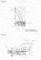
- Fig. 4 is a schematic sectional view illustrating the position of the slidable valve and the position of the injection port of the screw compressor according to Embodiment 1 of the invention in the large-pressure difference mode, such as a 100% load (full load) or 75% load mode.
- Fig. 5 is a development view of the inner peripheral surface of the casing and the screw rotor of the screw compressor according to Embodiment 1 of the invention in the large-pressure difference mode, such as the 100% load (full load) or 75% load mode.
- the discharge timing is delayed to increase the internal volume ratio.
- the controller 109 controls the slidable valve 8 to move toward the discharge end (the left of Fig. 4 or 5 ), as illustrated with the outline arrow of Fig. 4 or 5 to delay the discharge timing.
- This movement shifts the injection port 8a of the slidable valve 8 to a first position where the injection port 8a communicates with the refrigerant liquid passage 1 b and the compression chamber 5.
- the injection port 8a at the first position thus brings the refrigerant liquid passage 1 b of the casing 1 into communication with the compression chamber 5 through the injection port 8a.
- the controller 109 controls the expansion valve 107 to adjust the amount of refrigerant liquid injected into the screw compressor 102, such that the discharge temperature detected by the discharge temperature sensor 102a is maintained constant.
- the refrigerant liquid having the adjusted volume is injected into the compression chamber 5 through the refrigerant liquid passage 1 b and the injection port 8a. That is, a constant discharge temperature can be achieved by the shift of position of the slidable valve 8 for varying the internal volume ratio appropriately for the large-pressure difference mode and the injection of refrigerant liquid into the screw compressor 102.
- the refrigerant liquid should preferably be injected before the pressure rise in the compression chamber 5. It is thus preferred that the first position be a position corresponding to the position from which the injection port 8 communicates with the compression chamber 5 at the completion of an suction operation (trapping) of suction gas in the compression chamber 5. In this case, the refrigerant liquid is injected at the beginning of the compression stroke just after the trapping of suction gas. The injecting operation is thus effectively conducted without outflow of main-stream refrigerant to the low-pressure compartment or inhibition of the suction operation of suction gas.
- a small-pressure difference mode such as a partial load mode (e.g., 50% or 25% load mode).
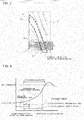
- Fig. 6 is a schematic sectional view illustrating the position of the injection port of the screw compressor according to Embodiment 1 of the invention in the small-pressure difference mode, such as a partial load mode (e.g., 50% or 25% load mode).
- Fig. 7 is a development view of the inner peripheral surface of the casing and the screw rotor of the screw compressor according to Embodiment 1 of the invention in the small-pressure difference mode, such as the partial load mode.
- the controller 109 controls the slidable valve 8 to move toward the suction end (the right of Fig. 6 or 7 ), as illustrated with the outline arrow of Fig. 6 or 7 .
- the slidable valve 8 is moved to a proper position for varying the internal volume ratio or the discharge timing appropriately for the small-pressure difference mode.
- the mode does not require injection of refrigerant liquid for lowering the discharge temperature, as described above.
- the injecting operation is thus not conducted.
- This mode requires a configuration for preventing the refrigerant liquid passage 1 b from functioning as a volume part (dead volume) subject to unnecessary compression.
- the injection port 8a is shifted to a position (hereinafter referred to as "second position") in the axial direction closer to the suction end than the first position is during the stop of the injecting operation according to Embodiment 1, as described in detail below.
- the injection port 8a at the second position does not communicate with the refrigerant liquid passage 1 b.
- the slidable valve 8 has two required functions in the small-pressure difference mode: the adjustment of the internal volume ratio and the shift of the injection port 8a to the second position.
- the movement of the slidable valve 8 to vary the internal volume ratio can shift the injection port 8a to the second position.
- the injection port 8a is shifted to the position in the axial direction so as not to communicate with the refrigerant liquid passage 1 b of the casing 1, in other words, so as to be separated from the refrigerant liquid passage 1 b in the small-pressure difference mode. Accordingly, the refrigerant liquid passage 1 b does not affect the compression chamber 5 from the intake stroke to the discharge stroke in the small-pressure difference mode.
- This configuration prevents the portion upstream of the refrigerant liquid passage 1 b from being a dead volume. Accordingly, the screw compressor 102 according to Embodiment 1 has a smaller dead volume than those of traditional screw compressors.
- the injection port 8a positioned at the second position does not communicate with the refrigerant liquid passage 1 b but communicates with the compression chamber 5. It is preferred that the injection port 8a at the second position does not communicate with the compression chamber 5 to reduce the dead volume and re-expansion loss.
- the injection port 8a positioned at the second position communicates with the compression chamber 5 due to the moving stroke of the slidable valve 8 and the opening timing of the discharge outlet 7 in response to the movement of the slidable valve 8.
- the injection port 8a at the second position should preferably be not communicating with the compression chamber 5 if possible. It should be noted that the configuration including the injection port 8a in communication with the compression chamber 5 can also reduce the re-expansion loss during the stop of the injecting operation because the second position is closer to the suction end than the first position is, as described in detail below.
- Fig. 8 illustrates a difference in timing of opening to the compression chamber in the screw compressor according to Embodiment 1 of the invention between the case of the injection port at the first position and the case of the injection port at the second position.
- Fig. 8 also illustrates the relationship between the rotational angle of the screw and the pressure in the compression chamber 5 (the internal pressure of the screw grooves 5a) in the individual cases of the first position and the second position.
- the timing of opening of the injection port 8a at the second position to the compression chamber 5 is earlier than that of the injection port 8a at the first position.
- the internal space of the injection port 8a is compressed within a small range of rotational angle of the screw. Accordingly, the injection port 8a at the second position can reduce the re-expansion loss in the partial load mode.
- the slidable valve 8 has two functions: the adjustment of the internal volume ratio and the shift of the injection port 8a.
- the movement of the slidable valve 8 can shift the injection port 8a between the first position and the second position, thereby switching the mode of the refrigerant liquid passage 1 b in communication with the compression chamber 5 through the injection port 8a to the mode of the refrigerant liquid passage 1 b not communicating with the compression chamber 5, and vice versa, depending on the operational condition.
- the injecting operation is conducted in a mode where the discharge temperature readily increases, such as a large-pressure difference mode (involving a pressure difference in the refrigeration cycle larger than a predetermined pressure difference or a predetermined compression ratio).
- a large-pressure difference mode involving a pressure difference in the refrigeration cycle larger than a predetermined pressure difference or a predetermined compression ratio.
- the refrigerant liquid passage 1 b is separated from the compression chamber 5 in a mode where the discharge temperature does not readily increase, such as a small-pressure difference mode (involving a pressure difference in the refrigeration cycle equal to or smaller than the predetermined pressure difference or the predetermined compression ratio).
- the refrigerant liquid passage 1 b thus has no dead volume. This configuration can reduce the pressure increase in the injection port 8a and can thus reduce the re-expansion loss and achieve high coefficient of performance.
- the injection port 8a is provided to the slidable valve 8 for varying the internal volume ratio and is controlled to be at an appropriate position.
- the screw compressor 102 and the refrigeration cycle apparatus 100 are provided that can thereby achieve high coefficient of performance in a wide range of operation and the screw compressor can have a low cost structure with high reliability.
- Embodiment 2 differs from Embodiment 1 in the connection of pipes in the refrigeration cycle apparatus 100.
- Fig. 9 illustrates a refrigerant circuit of a refrigeration cycle apparatus including a screw compressor according to Embodiment 2 of the invention.
- Embodiment 2 will focus on the difference from Embodiment 1.
- the components not described in Embodiment 2 are same as to those in Embodiment 1.
- the device according to Embodiment 2 further includes a refrigerant liquid pipe 108 branching from a portion between the condenser 103 and the expansion valve 105 and connected to a portion between the evaporator 106 and the screw compressor 102, in addition to the configuration of Embodiment 1.
- the refrigerant liquid pipe 108 is provided with a solenoid valve and/or an expansion mechanism (e.g., a fixed throttle or expansion valve) 110 in the intermediate part.
- the illustrated configuration includes the expansion mechanism 110 alone.
- the expansion mechanism 110 is open only while the injection port 8a resides at the second position, and varies the volume of injection based on the discharge temperature detected by the discharge temperature sensor 102a.
- the refrigeration cycle apparatus has a low discharge temperature and does not require the injection of refrigerant liquid in the small-pressure difference mode, and thus does not conduct the injecting operation, as described above.
- the slidable valve 8 is moved to shift the injection port 8a to the second position in the small-pressure difference mode, as in Embodiment 1.
- This configuration has a decreased dead volume and a decreased range of rotational angle of the screw (X in Fig. 8 ) overlapping with the compression stroke. The configuration can thus reduce the re-expansion loss.
- a transitional operation, activating operation, or pull-down operation may however cause a high temperature (intake temperature) and a high degree of superheat of intake refrigerant.
- a high intake temperature may also raise the temperature of the discharged gas.
- the controller 109 according to Embodiment 2 opens the expansion mechanism 110 to inject refrigerant liquid from the refrigerant liquid pipe 108 into the compression chamber 5, in response to an increase in discharge temperature above a reference temperature and the requirement for injection of refrigerant liquid.
- this configuration can lower the discharge temperature through the injection of the refrigerant liquid into the portion between the evaporator 106 and the screw compressor 102, in contrast to Embodiment 1.
- the configuration can thus ensure high reliability of the screw compressor 102.
- the expansion mechanism 110 provided to the refrigerant liquid pipe 108 may also be controlled based on the temperature or degree of superheat of intake refrigerant.
- Embodiment 2 can bring about effects equivalent to those of Embodiment 1, and ensure high reliability of the screw compressor 102 regardless of a sudden change in operation, such as an increase in temperature of suction gas, in the small-pressure difference mode.
Abstract
Description
- The present invention relates to a screw compressor and a refrigeration cycle apparatus.
- A traditional screw compressor includes a screw rotor having one end or a suction end and the other end or discharge end of fluid, and a columnar slidable valve disposed around the screw rotor and slides along the rotational axis of the screw rotor (see, for example, Patent Literature 1). The sliding movement of the slidable valve in the axial direction of the screw rotor shifts the position for start of discharge (completion of compression) of high-pressure gas compressed in a compression chamber. This operation changes the opening timing of a discharge port, thereby varying the internal volume ratio. The internal volume ratio indicates the ratio of the volume of the compression chamber just before a discharging operation to the volume of the compression chamber at the completion of an suction operation (start of compression).
- In
Patent Literature 1, the stop position of the slidable valve is controlled to achieve an internal volume ratio providing high compression efficiency, in response to the compression ratio (ratio of the discharge pressure to the intake pressure) depending on the operational loads. In other words, the slidable valve is shifted depending on the operational mode, i.e., a full load mode or a partial load mode. In detail, the slidable valve is shifted to the suction end in the partial load mode to advance the opening timing of the discharge port, and is shifted to the discharge end in the full load mode to delay the opening timing of the discharge port. - In a typical traditional refrigeration cycle apparatus including a screw compressor, refrigerant liquid is injected into a compression chamber through an injection port of the screw compressor to avoid an excess increase in the temperature of discharged gas, thereby optimizing the temperature and degree of superheat of the discharged gas (see, for example, Patent Literature 2).
-
- Patent Literature 1: Japanese Unexamined Patent Application Publication No.
2011-132834 Fig. 6 ) - Patent Literature 2: Japanese Unexamined Patent Application Publication No.
H5-10613 Fig. 1 ) - For these refrigeration cycle apparatuses equipped with screw compressors, the energy saving performance had been generally represented by the coefficient of performance (ratio of the refrigeration capacity to an electric power consumption) under the rated condition (full load condition: 100% load). However, indexes approximating the actual operational conditions, for example, an integrated part load value (IPLV) standardized in the United States, are recently drawing attentions..
- Atypical refrigeration cycle apparatus runs under the rated condition in a very short period of the year. In detail, the refrigeration cycle apparatus runs under the partial load mode for 90% or more of the gross annual operation time. In most of the partial load mode, the refrigeration cycle apparatus is operated under 75% to 50% of the full load. The full load mode differs from the partial load mode in the flow rate of refrigerant circulation, operational compression ratio, and coefficient of performance. These circumstances of the actual operation draw attention on the IPLV, which is an index based on the coefficient of performance under the partial load condition.
- Because in an operational mode involving a large high-low pressure difference, such as the full load mode, the discharge temperature of the gas discharged from a screw compressor readily rises, an injecting operation for injecting refrigerant liquid into a compression chamber is effective for lowering the discharge temperature. By contrast, in an operational mode involving a small pressure difference, such as the partial load (low load) mode, as the pressure difference decreases, the discharge temperature less readily rises. Thus this mode does not require the injection of refrigerant liquid. Such unnecessary injection of refrigerant liquid increases the input and impairs the performance in the partial load mode. To avoid this problem, the injecting operation is stopped in the small-pressure difference mode.
-
Patent Literature 1 discloses a technique of varying the internal volume ratio with the slidable valve to control the operational capacity, but does not discuss the prevention of an excess increase in the discharge temperature by the injecting operation. The prevention of an excessive increase in the discharge temperature is important, because such an excessive increase in the discharge temperature causes seizure due to disappearance of the gap between a screw rotor of the screw compressor and a casing and deteriorates refrigerating machine oil or refrigerant and thus impairs the reliability of the operation. - Although
Patent Literature 2 discusses this respect, the device disclosed inPatent Literature 2 has a problem during the stop of the injecting operation depending on the position of the injection port, as follows: Although the position of the injection port is not clearly described inPatent Literature 2, a typical injection port is disposed in a fixed position in a casing accommodating the screw rotor so as to communicate with the compression chamber. It is presumed that the position of the injection port is generally determined for achieving sufficient effects of the injecting operation. Unfortunately, this injection port functions as a volume part (dead volume) subject to unnecessary compression from low pressure to high pressure during the stop of the injecting operation. That is, during the stop of the injecting operation in the small-pressure difference mode, the injection port causes re-expansion loss while passing over the compression chamber without injection of refrigerant liquid, thereby impairing the performance of the screw compressor. - The present invention is made to address the above problem and an object thereof is to provide a screw compressor and a refrigeration cycle apparatus that have a controllable internal volume ratio and in which the position of an injection port is set to an appropriate position to achieve high coefficient of performance in a wide range of operation, and ensure high reliability and high performance with a low cost structure.
- A screw compressor according to an embodiment of the invention includes a casing; a screw rotor disposed to be rotatable in the casing; a compression chamber defined between the casing and the screw rotor, the compression chamber being configured to compress refrigerant gas; a slide groove extending on an inner peripheral surface of the casing along a rotational axis of the screw rotor; a refrigerant liquid passage formed in the casing, the refrigerant liquid passage being configured to communicate between an outside of the casing and the slide groove; and a slidable valve slidable on the slide groove along the rotational axis of the screw rotor, the slidable valve being configured to vary an internal volume ratio, the slidable valve having an injection port configured to allow the refrigerant liquid passage to communicate with the compression chamber depending on a position of the slidable valve, the slidable valve being configured to shift between a first position and a second position, the injection port communicating with the refrigerant liquid passage at the first position, the injection port not communicating with the refrigerant liquid passage at the second position, the second position being closer to a suction side of the screw compressor than the first position.
- A refrigeration cycle apparatus according to an embodiment of the invention includes a refrigerant circuit including the above screw compressor, a condenser, an expansion device, and an evaporator connected in sequence with refrigerant pipes; and an injection pipe branching from a portion between the condenser and the expansion device and connected to the refrigerant liquid passage of the screw compressor through an expansion valve.
- An embodiment of the invention can provide a screw compressor and a refrigeration cycle apparatus that have a controllable discharge timing and include an injection port shifted to an appropriate position to achieve high coefficient of performance in a wide range of operation, and ensure high reliability and high performance with a low cost structure.
-
- [
Fig. 1] Fig. 1 illustrates a refrigerant circuit of a refrigeration cycle apparatus including a screw compressor according toEmbodiment 1 of the invention. - [
Fig. 2] Fig. 2 is a schematic longitudinal-sectional view of a screw compressor according toEmbodiment 1 of the invention. - [
Fig. 3] Fig. 3 illustrates the principle of compression in a screw compressor according toEmbodiment 1 of the invention. - [
Fig. 4] Fig. 4 is a schematic sectional view illustrating the position of an injection port of a screw compressor according toEmbodiment 1 of the invention in a large-pressure difference mode, such as a full load mode. - [
Fig. 5] Fig. 5 is a development view of the inner peripheral surface of a casing and a screw rotor of a screw compressor according toEmbodiment 1 of the invention in a large-pressure difference mode, such as a full load mode. - [
Fig. 6] Fig. 6 is a schematic sectional view illustrating the position of an injection port of a screw compressor according toEmbodiment 1 of the invention in a small-pressure difference mode, such as a partial load mode. - [
Fig. 7] Fig. 7 is a development view of the inner peripheral surface of a casing and a screw rotor of a screw compressor according toEmbodiment 1 of the invention in a small-pressure difference mode, such as a partial load mode. - [
Fig. 8] Fig. 8 illustrates a difference in timing of opening to a compression chamber in a screw compressor according toEmbodiment 1 of the invention between the case of an injection port residing at a first position and the case of the injection port residing at a second position. - [
Fig. 9] Fig. 9 illustrates a refrigerant circuit of a refrigeration cycle apparatus including a screw compressor according toEmbodiment 2 of the invention. Description of Embodiments - Embodiments of the invention will now be described with reference to the accompanying drawings. A single-screw compressor equipped with a single screw rotor engaged with two gate rotors is described as an example in the description of the embodiments .
-
Fig. 1 illustrates a refrigerant circuit of a refrigeration cycle apparatus including a screw compressor according toEmbodiment 1 of the invention. In the accompanying drawings includingFig. 1 , the components having the same reference sign are same as or equivalent to each other throughout the following description. The embodiments of the components disclosed in the entire specification are given for mere illustration and should not be construed to limit the invention. In particular, the combinations of the components in the embodiments should not be construed to limit the invention, and the components in one embodiment may be appropriately applied to any other embodiment. High and low pressures are not absolutely determined relative to a fixed reference value, but relatively determined based on the state and operation of the system and device. - A
refrigeration cycle apparatus 100 is equipped with a refrigerant circuit including ascrew compressor 102 driven by aninverter 101, acondenser 103, an expansion valve 105 (that is a pressure-reducing device), and anevaporator 106 which are connected in sequence with refrigerant pipes. Therefrigeration cycle apparatus 100 further includes aninjection pipe 104 branching from a portion between thecondenser 103 and theexpansion valve 105 and connected to thescrew compressor 102 through anexpansion valve 107. - The
condenser 103 cools and condenses gas discharged from thescrew compressor 102. Theexpansion valve 105 performs throttle expansion to main-stream refrigerant from thecondenser 103. Theevaporator 106 evaporates the main-stream refrigerant from theexpansion valve 105. - The
screw compressor 102 is provided with adischarge temperature sensor 102a adjacent to the discharge end of thescrew compressor 102. Thedischarge temperature sensor 102a detects the temperature (discharge temperature) of gas discharged from thescrew compressor 102. The discharge temperature detected by thedischarge temperature sensor 102a is output to a controller 109 (described below). - The
refrigeration cycle apparatus 100 further includes acontroller 109. Thecontroller 109 is composed of, for example, a microcomputer including a CPU, RAM, and ROM, and controls the entirerefrigeration cycle apparatus 100 under instructions of a control program stored in the ROM. Thecontroller 109 controls theinverter 101 and theexpansion valve 105, shifts the position of a slidable valve 8 (described below) of thescrew compressor 102, controls the drive and stop of an injecting operation (injection of refrigerant liquid decompressed in theexpansion valve 107 into the screw compressor 102), and varies the amount of refrigerant liquid injected into acompression chamber 5 in the injecting operation. - The
screw compressor 102 according toEmbodiment 1 of the invention will now be described with reference toFig. 2 . -
Fig. 2 is a schematic longitudinal-sectional view of the screw compressor according toEmbodiment 1 of the invention. - With reference to
Fig. 2 , thescrew compressor 102 includes atubular casing 1 accommodating amotor 2. Themotor 2 is equipped with astator 2a fixed to the inner surface of thecasing 1 and a motor rotor 2b disposed inside thestator 2a. - The
casing 1 also accommodates ascrew rotor 3. Thescrew rotor 3 and the motor rotor 2b are disposed on the same axis and fixed to ascrew shaft 4. Thescrew rotor 3 hashelical screw grooves 5a on the outer peripheral surface, and is coupled to the motor rotor 2b fixed to thescrew shaft 4 to be rotated. Thescrew grooves 5a engage withteeth 6a ofgate rotors 6. A space surrounded by theteeth 6a of thegate rotors 6, thescrew grooves 5a, and the inner peripheral surface of thecasing 1 defines acompression chamber 5. Thecasing 1 is divided by a partition (not shown) into a low-pressure compartment (adjacent to the suction end) and a high-pressure compartment (adjacent to the discharge end). The high-pressure compartment has a discharge outlet 7 (refer toFig. 3 described below) in communication with a discharge chamber (not shown). - With reference to
Fig. 2 , the inner peripheral surface of thecasing 1 has aslide groove 1a extending along the rotational axis of thescrew rotor 3. Theslide groove 1 a accommodates aslidable valve 8 for varying the internal volume ratio, such that theslidable valve 8 can slide on theslide groove 1a. Theslidable valve 8 and thecasing 1 constitute part of the inner peripheral surface to define thecompression chamber 5. Theslidable valve 8 has aninjection port 8a to vary the internal volume ratio and shift theinjection port 8a. Theinjection port 8a penetrates through theslidable valve 8 from the outer surface sliding on theslide groove 1 a to the inner surface sliding on thescrew rotor 3.Fig. 2 illustrates an example of thecasing 1 that accommodates a singleslidable valve 8 having theinjection port 8a. - The
drive unit 10 for driving theslidable valve 8 is a unit such as those powered by gas pressure or oil pressure, or powered by a motor other than a piston, and the driving method is not limited. - The
slidable valve 8 constitutes part of thedischarge outlet 7. The sliding movement of theslidable valve 8 in the axial direction can change the discharge timing and thus vary the internal volume ratio. In detail, theslidable valve 8 shifted adjacent to the suction end allows thedischarge outlet 7 to open earlier and thus achieve an advanced discharge timing, whereas theslidable valve 8 shifted adjacent to the discharge end allows thedischarge outlet 7 to open later and thus achieve a delayed discharge timing. The advanced discharge timing provides an operation of a small internal volume ratio, whereas the delayed discharge timing provides an operation of a large internal volume ratio. - In general, a screw compressor has a proper compression ratio matching the internal volume ratio. The screw compressor does not cause any loss due to improper compression in an operational mode of the proper compression ratio. In an operational mode of a compression ratio smaller than the proper compression ratio, however, the gas is over-compressed before the opening of an outlet to have a pressure higher than the discharge pressure, resulting in unnecessary compression. In an operational mode of a compression ratio larger than the proper compression ratio, the outlet opens before achieving the discharge pressure, resulting in insufficient compression that causes reverse flow of gas. To address this problem, the position of the
slidable valve 8 is adjusted for optimizing the discharge timing. - The
casing 1 has arefrigerant liquid passage 1 b for introducing refrigerant liquid separating from the portion between thecondenser 103 and theexpansion valve 105 into thescrew grooves 5a (compression chamber 5). Therefrigerant liquid passage 1 b communicates with thecompression chamber 5 through theinjection port 8a. Therefrigerant liquid passage 1b is also connected to theinjection pipe 104. In this configuration, the refrigerant liquid flowing out of thecondenser 103 separates, and then flows through theinjection pipe 104, therefrigerant liquid passage 1 b, and theinjection port 8a into thecompression chamber 5. - The operations of the
screw compressor 102 and the refrigeration cycle apparatus will now be explained according toEmbodiment 1. -
Fig. 3 illustrates the principle of compression in the screw compressor according toEmbodiment 1 of the invention. - With reference to
Fig. 3 , the rotation of thescrew rotor 3 driven by the motor 2 (seeFig. 2 ) via the screw shaft 4 (seeFig. 2 ) relatively moves theteeth 6a of thegate rotors 6 in the compression chamber 5 (screwgrooves 5a). With this operation, an intake stroke, a compression stroke, and a discharge stroke are carried out at thecompression chamber 5 as one cycle, and the cycle is repeated. The individual strokes in thecompression chamber 5, which is illustrated with dotted hatching inFig. 3 , will now be explained. -
Fig. 3(a) illustrates the state of thecompression chamber 5 during the intake stroke. Thescrew rotor 3 is driven by themotor 2 to rotate along the direction of the solid arrow. This rotation reduces the volume of thecompression chamber 5, as illustrated inFig. 3(b) . - Further rotation of the
screw rotor 3 causes thecompression chamber 5 to communicate with thedischarge outlet 7, as illustrated inFig. 3(c) . The high-pressure refrigerant gas compressed in thecompression chamber 5 is thus discharged to the outside through thedischarge outlet 7. The same compression is performed again behind thescrew rotor 3. - Although the
injection port 8a, theslidable valve 8 having theinjection port 8a, and theslide groove 1 a are not illustrated inFig. 3 , the injecting operation causes the refrigerant liquid to enter thecompression chamber 5 from theinjection port 8a during the compression stroke. The refrigerant liquid flowing in thecompression chamber 5 is compressed together with suction gas, and is discharged to the outside during the discharge stroke. - The following explanation will focus on the positional relationship of the
injection port 8a with therefrigerant liquid passage 1 b and the compression chamber 5 (screwgrooves 5a) in a large-pressure difference mode, such as a 100% load (full load) or 75% load mode. -
Fig. 4 is a schematic sectional view illustrating the position of the slidable valve and the position of the injection port of the screw compressor according toEmbodiment 1 of the invention in the large-pressure difference mode, such as a 100% load (full load) or 75% load mode.Fig. 5 is a development view of the inner peripheral surface of the casing and the screw rotor of the screw compressor according toEmbodiment 1 of the invention in the large-pressure difference mode, such as the 100% load (full load) or 75% load mode. - In the large-pressure difference mode, the discharge timing is delayed to increase the internal volume ratio. In detail, the
controller 109 controls theslidable valve 8 to move toward the discharge end (the left ofFig. 4 or5 ), as illustrated with the outline arrow ofFig. 4 or5 to delay the discharge timing. This movement shifts theinjection port 8a of theslidable valve 8 to a first position where theinjection port 8a communicates with therefrigerant liquid passage 1 b and thecompression chamber 5. Theinjection port 8a at the first position thus brings therefrigerant liquid passage 1 b of thecasing 1 into communication with thecompression chamber 5 through theinjection port 8a. - During the compression stroke, the
controller 109 controls theexpansion valve 107 to adjust the amount of refrigerant liquid injected into thescrew compressor 102, such that the discharge temperature detected by thedischarge temperature sensor 102a is maintained constant. The refrigerant liquid having the adjusted volume is injected into thecompression chamber 5 through therefrigerant liquid passage 1 b and theinjection port 8a. That is, a constant discharge temperature can be achieved by the shift of position of theslidable valve 8 for varying the internal volume ratio appropriately for the large-pressure difference mode and the injection of refrigerant liquid into thescrew compressor 102. - The refrigerant liquid should preferably be injected before the pressure rise in the
compression chamber 5. It is thus preferred that the first position be a position corresponding to the position from which theinjection port 8 communicates with thecompression chamber 5 at the completion of an suction operation (trapping) of suction gas in thecompression chamber 5. In this case, the refrigerant liquid is injected at the beginning of the compression stroke just after the trapping of suction gas. The injecting operation is thus effectively conducted without outflow of main-stream refrigerant to the low-pressure compartment or inhibition of the suction operation of suction gas. - The following explanation will focus on the positional relationship of the
injection port 8a with therefrigerant liquid passage 1 b and the compression chamber 5 (screwgrooves 5a) in a small-pressure difference mode, such as a partial load mode (e.g., 50% or 25% load mode). -
Fig. 6 is a schematic sectional view illustrating the position of the injection port of the screw compressor according toEmbodiment 1 of the invention in the small-pressure difference mode, such as a partial load mode (e.g., 50% or 25% load mode).Fig. 7 is a development view of the inner peripheral surface of the casing and the screw rotor of the screw compressor according toEmbodiment 1 of the invention in the small-pressure difference mode, such as the partial load mode. - In the small-pressure difference mode, such as the partial load mode, the
controller 109 controls theslidable valve 8 to move toward the suction end (the right ofFig. 6 or7 ), as illustrated with the outline arrow ofFig. 6 or7 . In detail, theslidable valve 8 is moved to a proper position for varying the internal volume ratio or the discharge timing appropriately for the small-pressure difference mode. - Because of a low discharge temperature in the small-pressure difference mode, such as the partial load mode, the mode does not require injection of refrigerant liquid for lowering the discharge temperature, as described above. The injecting operation is thus not conducted. This mode requires a configuration for preventing the
refrigerant liquid passage 1 b from functioning as a volume part (dead volume) subject to unnecessary compression. To meet this requirement, theinjection port 8a is shifted to a position (hereinafter referred to as "second position") in the axial direction closer to the suction end than the first position is during the stop of the injecting operation according toEmbodiment 1, as described in detail below. Theinjection port 8a at the second position does not communicate with therefrigerant liquid passage 1 b. - In other words, the
slidable valve 8 has two required functions in the small-pressure difference mode: the adjustment of the internal volume ratio and the shift of theinjection port 8a to the second position. The movement of theslidable valve 8 to vary the internal volume ratio can shift theinjection port 8a to the second position. - As described above, the
injection port 8a is shifted to the position in the axial direction so as not to communicate with therefrigerant liquid passage 1 b of thecasing 1, in other words, so as to be separated from therefrigerant liquid passage 1 b in the small-pressure difference mode. Accordingly, therefrigerant liquid passage 1 b does not affect thecompression chamber 5 from the intake stroke to the discharge stroke in the small-pressure difference mode. This configuration prevents the portion upstream of therefrigerant liquid passage 1 b from being a dead volume. Accordingly, thescrew compressor 102 according toEmbodiment 1 has a smaller dead volume than those of traditional screw compressors. - In
Fig. 6 or7 , theinjection port 8a positioned at the second position does not communicate with therefrigerant liquid passage 1 b but communicates with thecompression chamber 5. It is preferred that theinjection port 8a at the second position does not communicate with thecompression chamber 5 to reduce the dead volume and re-expansion loss. In the illustrated example, theinjection port 8a positioned at the second position communicates with thecompression chamber 5 due to the moving stroke of theslidable valve 8 and the opening timing of thedischarge outlet 7 in response to the movement of theslidable valve 8. Theinjection port 8a at the second position, however, should preferably be not communicating with thecompression chamber 5 if possible. It should be noted that the configuration including theinjection port 8a in communication with thecompression chamber 5 can also reduce the re-expansion loss during the stop of the injecting operation because the second position is closer to the suction end than the first position is, as described in detail below. - The difference in timing of opening to the
compression chamber 5 depending on the position of theinjection port 8a will now be described. -
Fig. 8 illustrates a difference in timing of opening to the compression chamber in the screw compressor according toEmbodiment 1 of the invention between the case of the injection port at the first position and the case of the injection port at the second position.Fig. 8 also illustrates the relationship between the rotational angle of the screw and the pressure in the compression chamber 5 (the internal pressure of thescrew grooves 5a) in the individual cases of the first position and the second position. - With reference to
Fig. 8 , the timing of opening of theinjection port 8a at the second position to thecompression chamber 5 is earlier than that of theinjection port 8a at the first position. This indicates that the range of rotational angle of the screw (X inFig. 8 ) overlapping with the compression stroke is small inFig. 8 . In other words, the internal space of theinjection port 8a is compressed within a small range of rotational angle of the screw. Accordingly, theinjection port 8a at the second position can reduce the re-expansion loss in the partial load mode. - As described above, the
slidable valve 8 according toEmbodiment 1 has two functions: the adjustment of the internal volume ratio and the shift of theinjection port 8a. The movement of theslidable valve 8 can shift theinjection port 8a between the first position and the second position, thereby switching the mode of therefrigerant liquid passage 1 b in communication with thecompression chamber 5 through theinjection port 8a to the mode of therefrigerant liquid passage 1 b not communicating with thecompression chamber 5, and vice versa, depending on the operational condition. - The injecting operation is conducted in a mode where the discharge temperature readily increases, such as a large-pressure difference mode (involving a pressure difference in the refrigeration cycle larger than a predetermined pressure difference or a predetermined compression ratio). This configuration can prevent an excessive increase in the discharge temperature and ensure high reliability of the screw compressor. The
refrigerant liquid passage 1 b is separated from thecompression chamber 5 in a mode where the discharge temperature does not readily increase, such as a small-pressure difference mode (involving a pressure difference in the refrigeration cycle equal to or smaller than the predetermined pressure difference or the predetermined compression ratio). Therefrigerant liquid passage 1 b thus has no dead volume. This configuration can reduce the pressure increase in theinjection port 8a and can thus reduce the re-expansion loss and achieve high coefficient of performance. - According to
Embodiment 1, theinjection port 8a is provided to theslidable valve 8 for varying the internal volume ratio and is controlled to be at an appropriate position. Thescrew compressor 102 and therefrigeration cycle apparatus 100 are provided that can thereby achieve high coefficient of performance in a wide range of operation and the screw compressor can have a low cost structure with high reliability. -
Embodiment 2 differs fromEmbodiment 1 in the connection of pipes in therefrigeration cycle apparatus 100. -
Fig. 9 illustrates a refrigerant circuit of a refrigeration cycle apparatus including a screw compressor according toEmbodiment 2 of the invention. The following description ofEmbodiment 2 will focus on the difference fromEmbodiment 1. The components not described inEmbodiment 2 are same as to those inEmbodiment 1. - The device according to
Embodiment 2 further includes arefrigerant liquid pipe 108 branching from a portion between thecondenser 103 and theexpansion valve 105 and connected to a portion between theevaporator 106 and thescrew compressor 102, in addition to the configuration ofEmbodiment 1. Therefrigerant liquid pipe 108 is provided with a solenoid valve and/or an expansion mechanism (e.g., a fixed throttle or expansion valve) 110 in the intermediate part. The illustrated configuration includes theexpansion mechanism 110 alone. Theexpansion mechanism 110 is open only while theinjection port 8a resides at the second position, and varies the volume of injection based on the discharge temperature detected by thedischarge temperature sensor 102a. - In general, the refrigeration cycle apparatus has a low discharge temperature and does not require the injection of refrigerant liquid in the small-pressure difference mode, and thus does not conduct the injecting operation, as described above. The
slidable valve 8 is moved to shift theinjection port 8a to the second position in the small-pressure difference mode, as inEmbodiment 1. This configuration has a decreased dead volume and a decreased range of rotational angle of the screw (X inFig. 8 ) overlapping with the compression stroke. The configuration can thus reduce the re-expansion loss. - Even in the small-pressure difference mode, a transitional operation, activating operation, or pull-down operation may however cause a high temperature (intake temperature) and a high degree of superheat of intake refrigerant. Such a high intake temperature may also raise the temperature of the discharged gas. To solve this problem, the
controller 109 according toEmbodiment 2 opens theexpansion mechanism 110 to inject refrigerant liquid from therefrigerant liquid pipe 108 into thecompression chamber 5, in response to an increase in discharge temperature above a reference temperature and the requirement for injection of refrigerant liquid. - In the case of an increase in discharge temperature in the small-pressure difference mode, this configuration can lower the discharge temperature through the injection of the refrigerant liquid into the portion between the
evaporator 106 and thescrew compressor 102, in contrast toEmbodiment 1. The configuration can thus ensure high reliability of thescrew compressor 102. Theexpansion mechanism 110 provided to therefrigerant liquid pipe 108 may also be controlled based on the temperature or degree of superheat of intake refrigerant. - As described above,
Embodiment 2 can bring about effects equivalent to those ofEmbodiment 1, and ensure high reliability of thescrew compressor 102 regardless of a sudden change in operation, such as an increase in temperature of suction gas, in the small-pressure difference mode. - 1 casing 1 a
slide groove 1 brefrigerant liquid passage 2motor 2a stator2b motor rotor 3screw rotor 4screw shaft 5compression chamber 5a screw groove 6gate 7rotor 6a toothoutlet 8slidable valve 8a injection port 9coupling rod 10drive unit 100refrigeration cycle apparatus 101inverter 102screw compressor 102adischarge temperature sensor 103condenser 104injection pipe 105expansion valve 106evaporator 107expansion valve 108 refrigerantliquid pipe 109controller 110 expansion mechanism
Claims (5)
- A screw compressor comprising:a casing;a screw rotor disposed to be rotatable in the casing;a compression chamber defined between the casing and the screw rotor, the compression chamber being configured to compress refrigerant gas;a slide groove extending on an inner peripheral surface of the casing along a rotational axis of the screw rotor;a refrigerant liquid passage formed in the casing, the refrigerant liquid passage being configured to communicate between an outside of the casing and the slide groove; anda slidable valve slidable on the slide groove along the rotational axis of the screw rotor, the slidable valve being configured to vary an internal volume ratio,the slidable valve having an injection port configured to allow the refrigerant liquid passage to communicate with the compression chamber depending on a position of the slidable valve,the slidable valve being configured to shift between a first position and a second position, the injection port communicating with the refrigerant liquid passage at the first position, the injection port not communicating with the refrigerant liquid passage at the second position, the second position being closer to a suction side of the screw compressor than the first position.
- The screw compressor of claim 1, wherein the slidable valve is positioned at the first position in a large-pressure difference mode having a pressure difference larger than a predetermined pressure difference in a refrigeration cycle including the screw compressor, or positioned at the second position in a small-pressure difference mode having a pressure difference equal to or smaller than the predetermined pressure difference in the refrigeration cycle.
- The screw compressor of claim 1 or 2, further comprising a motor to be driven by an inverter and to rotate the screw rotor.
- A refrigeration cycle apparatus comprising:a refrigerant circuit comprising the screw compressor of any one of claims 1 to 3, a condenser, a pressure-reducing device, and an evaporator connected in sequence with refrigerant pipes; anda refrigerant liquid pipe branching from a portion between the condenser and the pressure-reducing device, the refrigerant liquid pipe being connected to the refrigerant liquid passage of the screw compressor through an expansion valve.
- The refrigeration cycle apparatus of claim 4, further comprising a refrigerant liquid pipe branching from a portion between the condenser and the expansion device, the refrigerant liquid pipe being connected to a portion between the evaporator and the screw compressor through at least one of a solenoid valve and an expansion mechanism.
Applications Claiming Priority (1)
| Application Number | Priority Date | Filing Date | Title |
|---|---|---|---|
| PCT/JP2014/081284 WO2016084176A1 (en) | 2014-11-26 | 2014-11-26 | Screw compressor and refrigeration cycle device |
Publications (2)
| Publication Number | Publication Date |
|---|---|
| EP3225848A1 true EP3225848A1 (en) | 2017-10-04 |
| EP3225848A4 EP3225848A4 (en) | 2018-10-17 |
Family
ID=56073796
Family Applications (1)
| Application Number | Title | Priority Date | Filing Date |
|---|---|---|---|
| EP14906847.0A Withdrawn EP3225848A4 (en) | 2014-11-26 | 2014-11-26 | Screw compressor and refrigeration cycle device |
Country Status (3)
| Country | Link |
|---|---|
| EP (1) | EP3225848A4 (en) |
| JP (1) | JP6234611B2 (en) |
| WO (1) | WO2016084176A1 (en) |
Families Citing this family (4)
| Publication number | Priority date | Publication date | Assignee | Title |
|---|---|---|---|---|
| EP3505765B1 (en) * | 2016-08-23 | 2020-04-29 | Mitsubishi Electric Corporation | Screw compressor and refrigeration cycle device |
| EP3569950B1 (en) * | 2017-01-11 | 2022-03-16 | Mitsubishi Electric Corporation | Refrigeration cycle device |
| DE112020007548T5 (en) * | 2020-08-26 | 2023-06-15 | Mitsubishi Electric Corporation | COOLANT CIRCUIT DEVICE |
| CN114857793B (en) * | 2022-05-20 | 2023-03-31 | 珠海格力电器股份有限公司 | Condensing unit, liquid spraying control method and device thereof and air conditioner |
Family Cites Families (11)
| Publication number | Priority date | Publication date | Assignee | Title |
|---|---|---|---|---|
| US3859814A (en) * | 1973-10-03 | 1975-01-14 | Vilter Manufacturing Corp | Variable capacity rotary screw compressor |
| JPS5720864Y2 (en) * | 1977-01-12 | 1982-05-06 | ||
| JPS53101757A (en) * | 1977-02-18 | 1978-09-05 | Hitachi Ltd | Screw refrigerator |
| JPS55156291A (en) * | 1979-05-25 | 1980-12-05 | Hitachi Ltd | Screw compressor |
| JPH0820137B2 (en) * | 1990-09-26 | 1996-03-04 | ダイキン工業株式会社 | Screw refrigeration equipment |
| JPH05106572A (en) * | 1991-10-17 | 1993-04-27 | Daikin Ind Ltd | Single shaft type screw compressor |
| JP4183021B1 (en) * | 2007-06-11 | 2008-11-19 | ダイキン工業株式会社 | Compressor and refrigeration equipment |
| JP2009024534A (en) * | 2007-07-18 | 2009-02-05 | Daikin Ind Ltd | Refrigerating device |
| GB0821275D0 (en) * | 2008-11-20 | 2008-12-31 | Aaf Mcquay Inc | Screw compressor |
| EP3006740B1 (en) * | 2013-05-30 | 2018-11-14 | Mitsubishi Electric Corporation | Screw compressor and refrigeration cycle device |
| EP3199814B1 (en) * | 2014-09-24 | 2021-01-06 | Mitsubishi Electric Corporation | Screw compressor and refrigeration cycle device |
-
2014
- 2014-11-26 WO PCT/JP2014/081284 patent/WO2016084176A1/en active Application Filing
- 2014-11-26 EP EP14906847.0A patent/EP3225848A4/en not_active Withdrawn
- 2014-11-26 JP JP2016561149A patent/JP6234611B2/en active Active
Also Published As
| Publication number | Publication date |
|---|---|
| WO2016084176A1 (en) | 2016-06-02 |
| JP6234611B2 (en) | 2017-11-22 |
| EP3225848A4 (en) | 2018-10-17 |
| JPWO2016084176A1 (en) | 2017-04-27 |
Similar Documents
| Publication | Publication Date | Title |
|---|---|---|
| US11852145B2 (en) | Rotary compressors with variable speed and volume control | |
| EP3199814B1 (en) | Screw compressor and refrigeration cycle device | |
| EP1953388B1 (en) | Multistage compressor | |
| EP3225848A1 (en) | Screw compressor and refrigeration cycle device | |
| CN102216619B (en) | Screw compressor | |
| JP2006258397A (en) | Refrigerator | |
| JP6685379B2 (en) | Screw compressor and refrigeration cycle equipment | |
| CN109154455B (en) | Refrigeration cycle device | |
| US8920149B2 (en) | Single-screw compressor having an adjustment mechanism for adjusting a compression ratio of the compression chamber | |
| EP3133288B1 (en) | Screw compressor | |
| WO2017094057A1 (en) | Single-screw compressor and refrigeration cycle device | |
| WO2020245932A1 (en) | Screw compressor, and refrigeration cycle device | |
| EP3505765B1 (en) | Screw compressor and refrigeration cycle device | |
| WO2016046908A1 (en) | Screw compressor and refrigeration cycle device | |
| WO2022044149A1 (en) | Refrigeration cycle device | |
| EP3569950B1 (en) | Refrigeration cycle device | |
| EP3252310A1 (en) | Screw compressor | |
| EP3933204A1 (en) | Screw compressor | |
| EP4067659B1 (en) | Screw compressor | |
| TW201800668A (en) | Single screw compressor and refrigeration cycle device | |
| JP2014029158A (en) | Refrigeration device |
Legal Events
| Date | Code | Title | Description |
|---|---|---|---|
| PUAI | Public reference made under article 153(3) epc to a published international application that has entered the european phase |
Free format text: ORIGINAL CODE: 0009012 |
|
| 17P | Request for examination filed |
Effective date: 20170504 |
|
| AK | Designated contracting states |
Kind code of ref document: A1 Designated state(s): AL AT BE BG CH CY CZ DE DK EE ES FI FR GB GR HR HU IE IS IT LI LT LU LV MC MK MT NL NO PL PT RO RS SE SI SK SM TR |
|
| AX | Request for extension of the european patent |
Extension state: BA ME |
|
| DAX | Request for extension of the european patent (deleted) | ||
| RIC1 | Information provided on ipc code assigned before grant |
Ipc: F04C 28/12 20060101ALI20180528BHEP Ipc: F04C 28/26 20060101ALI20180528BHEP Ipc: F04C 18/16 20060101ALI20180528BHEP Ipc: F04C 29/04 20060101ALI20180528BHEP Ipc: F04C 18/52 20060101AFI20180528BHEP Ipc: F04C 29/00 20060101ALI20180528BHEP |
|
| A4 | Supplementary search report drawn up and despatched |
Effective date: 20180914 |
|
| RIC1 | Information provided on ipc code assigned before grant |
Ipc: F04C 29/00 20060101ALI20180911BHEP Ipc: F04C 18/52 20060101AFI20180911BHEP Ipc: F04C 29/04 20060101ALI20180911BHEP Ipc: F04C 28/12 20060101ALI20180911BHEP Ipc: F04C 18/16 20060101ALI20180911BHEP Ipc: F04C 28/26 20060101ALI20180911BHEP |
|
| STAA | Information on the status of an ep patent application or granted ep patent |
Free format text: STATUS: THE APPLICATION IS DEEMED TO BE WITHDRAWN |
|
| 18D | Application deemed to be withdrawn |
Effective date: 20190413 |