EP3660309B1 - Diaphragm pump - Google Patents
Diaphragm pump Download PDFInfo
- Publication number
- EP3660309B1 EP3660309B1 EP19209884.6A EP19209884A EP3660309B1 EP 3660309 B1 EP3660309 B1 EP 3660309B1 EP 19209884 A EP19209884 A EP 19209884A EP 3660309 B1 EP3660309 B1 EP 3660309B1
- Authority
- EP
- European Patent Office
- Prior art keywords
- shaft
- diaphragm
- pump
- valve
- housing
- Prior art date
- Legal status (The legal status is an assumption and is not a legal conclusion. Google has not performed a legal analysis and makes no representation as to the accuracy of the status listed.)
- Active
Links
- 239000013013 elastic material Substances 0.000 claims description 5
- 239000012530 fluid Substances 0.000 claims description 5
- 238000005192 partition Methods 0.000 description 11
- 238000003825 pressing Methods 0.000 description 10
- 238000005549 size reduction Methods 0.000 description 4
- 230000002093 peripheral effect Effects 0.000 description 3
- 230000007423 decrease Effects 0.000 description 2
- 230000005489 elastic deformation Effects 0.000 description 2
- 229920001971 elastomer Polymers 0.000 description 2
- 239000000463 material Substances 0.000 description 2
- 230000004048 modification Effects 0.000 description 2
- 238000012986 modification Methods 0.000 description 2
- 239000005060 rubber Substances 0.000 description 2
- 229920003051 synthetic elastomer Polymers 0.000 description 2
- 239000005061 synthetic rubber Substances 0.000 description 2
- 238000005520 cutting process Methods 0.000 description 1
- 239000007788 liquid Substances 0.000 description 1
- 238000004519 manufacturing process Methods 0.000 description 1
- 238000007789 sealing Methods 0.000 description 1
Images


Classifications
-
- F—MECHANICAL ENGINEERING; LIGHTING; HEATING; WEAPONS; BLASTING
- F04—POSITIVE - DISPLACEMENT MACHINES FOR LIQUIDS; PUMPS FOR LIQUIDS OR ELASTIC FLUIDS
- F04B—POSITIVE-DISPLACEMENT MACHINES FOR LIQUIDS; PUMPS
- F04B43/00—Machines, pumps, or pumping installations having flexible working members
- F04B43/02—Machines, pumps, or pumping installations having flexible working members having plate-like flexible members, e.g. diaphragms
-
- F—MECHANICAL ENGINEERING; LIGHTING; HEATING; WEAPONS; BLASTING
- F04—POSITIVE - DISPLACEMENT MACHINES FOR LIQUIDS; PUMPS FOR LIQUIDS OR ELASTIC FLUIDS
- F04B—POSITIVE-DISPLACEMENT MACHINES FOR LIQUIDS; PUMPS
- F04B45/00—Pumps or pumping installations having flexible working members and specially adapted for elastic fluids
- F04B45/04—Pumps or pumping installations having flexible working members and specially adapted for elastic fluids having plate-like flexible members, e.g. diaphragms
- F04B45/043—Pumps or pumping installations having flexible working members and specially adapted for elastic fluids having plate-like flexible members, e.g. diaphragms two or more plate-like pumping flexible members in parallel
-
- F—MECHANICAL ENGINEERING; LIGHTING; HEATING; WEAPONS; BLASTING
- F04—POSITIVE - DISPLACEMENT MACHINES FOR LIQUIDS; PUMPS FOR LIQUIDS OR ELASTIC FLUIDS
- F04B—POSITIVE-DISPLACEMENT MACHINES FOR LIQUIDS; PUMPS
- F04B39/00—Component parts, details, or accessories, of pumps or pumping systems specially adapted for elastic fluids, not otherwise provided for in, or of interest apart from, groups F04B25/00 - F04B37/00
- F04B39/10—Adaptations or arrangements of distribution members
-
- F—MECHANICAL ENGINEERING; LIGHTING; HEATING; WEAPONS; BLASTING
- F04—POSITIVE - DISPLACEMENT MACHINES FOR LIQUIDS; PUMPS FOR LIQUIDS OR ELASTIC FLUIDS
- F04B—POSITIVE-DISPLACEMENT MACHINES FOR LIQUIDS; PUMPS
- F04B39/00—Component parts, details, or accessories, of pumps or pumping systems specially adapted for elastic fluids, not otherwise provided for in, or of interest apart from, groups F04B25/00 - F04B37/00
- F04B39/12—Casings; Cylinders; Cylinder heads; Fluid connections
- F04B39/121—Casings
-
- F—MECHANICAL ENGINEERING; LIGHTING; HEATING; WEAPONS; BLASTING
- F04—POSITIVE - DISPLACEMENT MACHINES FOR LIQUIDS; PUMPS FOR LIQUIDS OR ELASTIC FLUIDS
- F04B—POSITIVE-DISPLACEMENT MACHINES FOR LIQUIDS; PUMPS
- F04B45/00—Pumps or pumping installations having flexible working members and specially adapted for elastic fluids
- F04B45/04—Pumps or pumping installations having flexible working members and specially adapted for elastic fluids having plate-like flexible members, e.g. diaphragms
-
- F—MECHANICAL ENGINEERING; LIGHTING; HEATING; WEAPONS; BLASTING
- F04—POSITIVE - DISPLACEMENT MACHINES FOR LIQUIDS; PUMPS FOR LIQUIDS OR ELASTIC FLUIDS
- F04B—POSITIVE-DISPLACEMENT MACHINES FOR LIQUIDS; PUMPS
- F04B53/00—Component parts, details or accessories not provided for in, or of interest apart from, groups F04B1/00 - F04B23/00 or F04B39/00 - F04B47/00
- F04B53/10—Valves; Arrangement of valves
- F04B53/1037—Flap valves
- F04B53/1047—Flap valves the valve being formed by one or more flexible elements
- F04B53/106—Flap valves the valve being formed by one or more flexible elements the valve being a membrane
- F04B53/1065—Flap valves the valve being formed by one or more flexible elements the valve being a membrane fixed at its centre
-
- F—MECHANICAL ENGINEERING; LIGHTING; HEATING; WEAPONS; BLASTING
- F04—POSITIVE - DISPLACEMENT MACHINES FOR LIQUIDS; PUMPS FOR LIQUIDS OR ELASTIC FLUIDS
- F04B—POSITIVE-DISPLACEMENT MACHINES FOR LIQUIDS; PUMPS
- F04B53/00—Component parts, details or accessories not provided for in, or of interest apart from, groups F04B1/00 - F04B23/00 or F04B39/00 - F04B47/00
- F04B53/16—Casings; Cylinders; Cylinder liners or heads; Fluid connections
-
- F—MECHANICAL ENGINEERING; LIGHTING; HEATING; WEAPONS; BLASTING
- F16—ENGINEERING ELEMENTS AND UNITS; GENERAL MEASURES FOR PRODUCING AND MAINTAINING EFFECTIVE FUNCTIONING OF MACHINES OR INSTALLATIONS; THERMAL INSULATION IN GENERAL
- F16K—VALVES; TAPS; COCKS; ACTUATING-FLOATS; DEVICES FOR VENTING OR AERATING
- F16K15/00—Check valves
- F16K15/14—Check valves with flexible valve members
- F16K15/148—Check valves with flexible valve members the closure elements being fixed in their centre
-
- F—MECHANICAL ENGINEERING; LIGHTING; HEATING; WEAPONS; BLASTING
- F04—POSITIVE - DISPLACEMENT MACHINES FOR LIQUIDS; PUMPS FOR LIQUIDS OR ELASTIC FLUIDS
- F04B—POSITIVE-DISPLACEMENT MACHINES FOR LIQUIDS; PUMPS
- F04B39/00—Component parts, details, or accessories, of pumps or pumping systems specially adapted for elastic fluids, not otherwise provided for in, or of interest apart from, groups F04B25/00 - F04B37/00
- F04B39/14—Provisions for readily assembling or disassembling
Definitions
- the present invention relates to a diaphragm pump including an umbrella valve made of an elastic material.
- a diaphragm pump including an umbrella valve is disclosed in, for example, Japanese Patent Laid-Open No. 2018-112127 (literature 1) and Japanese Patent Laid-Open No. 2013-192639 (literature 2).
- the diaphragm pump disclosed in literature 1 includes a suction valve formed from an umbrella valve.
- the suction valve will be described with reference to Figs. 7 and 8 .
- a suction valve 1 is attached to a through hole 3 of a housing member 2, and opens and closes a suction passage 5 formed in the housing member 2.
- the housing member 2 forms a pump chamber 8 together with a pump portion 7 of a diaphragm 6.
- the suction valve 1 includes a shaft 4 inserted into the through hole 3, and a plate-shaped valve element 9 integrally provided at one end portion of the shaft 4 located in the pump chamber 8.
- a stopper 4a having a diameter larger than the hole diameter of the through hole 3 and a knob portion 4b projecting from the stopper 4a in the longitudinal direction are provided at the other end portion of the shaft 4 shown in Fig. 7 .
- the knob portion 4b is formed long such that the stopper 4a is located in the middle part of the shaft 4, as shown in Fig. 8 .
- An umbrella valve disclosed in literature 2 includes a shaft, and a plate-shaped valve element formed at the center portion of the shaft in the axial direction.
- the umbrella valve is arranged between two housing members. One end portion of the shaft is fitted in the shaft hole of one housing member, and the other end portion is fitted in the shaft hole of the other housing member.
- the umbrella valve is configured such that the valve element is in tight contact with the seat surface of one housing member in a state in which the two end portions of the shaft are fitted in the shaft holes.
- the diaphragm pump disclosed in literature 1 since the knob portion 4b is cut after the umbrella valve is assembled in the housing member 2, cutting operations increase, resulting in an increase in cost. On the other hand, if a structure in which the knob portion 4b is left without being cut is employed, other parts cannot be arranged at optimum positions to avoid interference with the knob portion 4b, and the diaphragm pump becomes bulky. Hence, the diaphragm pump disclosed in literature 1 can hardly implement both cost reduction and size reduction because of the knob portion 4b of the umbrella valve.
- the umbrella valve disclosed in literature 2 can easily implement cost reduction and size reduction because the knob portion 4b is not necessary.
- the position of the valve element in the axial direction of the shaft is hard to be constant because of the manufacturing error of the shaft or the shaft holes of the housing members, and the accuracy of the position of the seal surface is low. For this reason, the force for pressing the valve element against the seat surface is not constant, and the quality varies.
- JP 2008 180171 A relates to a diaphragm pump and discloses subject matter according to the preamble of independent claim 1.
- a diaphragm pump comprising a diaphragm including a pump portion, a pump housing configured to store the diaphragm and form a pump chamber together with the pump portion, a suction passage through which a fluid flows to the pump chamber when the pump chamber expands, a discharge passage through which a fluid discharged from the pump chamber flows when the pump chamber contracts, a suction valve arranged in the suction passage and configured to open and close the suction passage, and a discharge valve arranged in the discharge passage and configured to open and close the discharge passage, wherein at least one valve of the suction valve and the discharge valve is made of an elastic material, and includes a shaft including a first end portion and a second end portion, and a plate-shaped valve element extending from the first end portion of the shaft in a direction orthogonal to an axis of the shaft, the pump housing includes a first housing member including a shaft hole formed from a blind hole in which the second end portion of the shaft
- a diaphragm according to an embodiment of the present invention will now be described in detail with reference to Figs. 1 to 6 .
- a diaphragm pump 11 shown in Fig. 1 is attached to a motor 12 located at the lowermost position in Fig. 1 .
- the diaphragm pump 11 is driven by the motor 12 and operates.
- the diaphragm pump 11 according to this embodiment is a pump that sucks and discharges air.
- the diaphragm pump 11 includes a driving unit 13 fixed to the motor 12, and a valve portion 14 attached to the driving unit 13.
- the driving unit 13 includes a driving unit housing 15 fixed to the motor 12, and a driving mechanism 16 stored in the housing 15.
- the housing 15 is formed into a bottomed cylindrical shape, and the driving mechanism 16 fixed to the motor 12 by fixing bolts 17 includes a crank body 19 attached to a rotating shaft 18 of the motor 12, a driving body 21 connected to the crank body 19 via a driving shaft 20, and the like.
- the driving shaft 20 tilts in a predetermined direction with respect to the rotating shaft 18.
- the driving body 21 includes a columnar shaft portion 22 rotatably supported by the driving shaft 20, and a plurality of arm portions 23 projecting outward from the shaft portion 22 in the radial direction.
- the arm portions 23 are provided for pump portions 25 of a diaphragm 24 to be described later, respectively, and radially extend outward from the shaft portion 22 in the radial direction.
- a through hole 23a is formed in each arm portion 23.
- a connecting piece 26 of the diaphragm 24 is inserted into the through hole 23a. The connecting piece 26 extends through the arm portion 23 and is fixed to the arm portions 23 in this state.
- the valve portion 14 includes a diaphragm holder 31 attached to the opening portion of the above-described driving unit housing 15, the diaphragm 24 arranged on the diaphragm holder 31, a diaphragm housing 32 attached to the diaphragm holder 31 in a state in which the diaphragm 24 is sandwiched between the diaphragm housing 32 and the diaphragm holder 31, a partition 33 arranged on the diaphragm housing 32, a cover 34 attached to the diaphragm housing 32 via the partition 33, and the like.
- the diaphragm holder 31, the diaphragm housing 32, and the cover 34 are each formed into a circular shape when viewed from the axial direction of the motor 12.
- the diaphragm holder 31, the diaphragm housing 32, the cover 34, and the above-described driving unit housing 15 form a pump housing 35.
- the pump housing 35 stores the above-described members including the diaphragm 24.
- the diaphragm holder 31 is formed into a disc shape connectable to the driving unit housing 15, and includes a plurality of through holes, as shown in Fig. 2 .
- the through holes include cylinder holes 36 for the pump portions, in which the pump portions 25 of the diaphragm 24 are inserted, and a suction hole 38 to be opened and closed by a suction valve 37.
- the cylinder holes 36 and the suction hole 38 open to a housing space S surrounded by the driving unit housing 15 and the diaphragm holder 31.
- the suction hole 38 forms part of a suction passage 51 to be described later, and makes the housing space S communicate with a circular concave portion 39 formed at the center portion of the diaphragm holder 31.
- a shaft hole 41 formed by a blind hole is formed at the center portion of the circular concave portion 39.
- a shaft 42 of the suction valve 37 is fitted in the shaft hole 41.
- the structure of the suction valve 37 will be described later.
- the bottom surface of the circular concave portion 39 is formed flat to form a seat surface 43. The suction hole 38 and the shaft hole 41 open to the seat surface 43.
- the diaphragm 24 is sandwiched between the diaphragm holder 31 and the diaphragm housing 32 and held.
- the diaphragm 24 includes the plurality of cup-shaped pump portions 25 that open toward the diaphragm housing 32, a plurality of first through holes 44 located on the center side of the diaphragm holder 31 with respect to the pump portions 25 and provided for the pump portions 25, respectively, a second through hole 45 located at the center portion of the diaphragm holder 31, a plurality of discharge valves 46 and a plurality of through holes 47, which are located on the outer periphery side of the diaphragm holder 31 with respect to the pump portions 25 and provided for the pump portions 25, respectively, and the like.
- the pump portions 25 are arranged at positions that divide the diaphragm 24 into a plurality of parts in the circumferential direction of the diaphragm holder 31.
- the pump portions 25 are inserted into the cylinder holes 36 formed in the diaphragm holder 31.
- the opening portions of the pump portions 25 are closed by the diaphragm housing 32.
- a pump chamber 48 is formed between each pump portion 25 and the diaphragm housing 32. That is, the pump housing 35 including the diaphragm housing 32 forms the pump chambers 48 together with the pump portions 25.
- a piston 49 is provided on the bottom of each pump portion 25 having a cup shape.
- the piston 49 is provided with the connecting piece 26 that projects in a direction opposite to the pump chamber 48.
- the connecting piece 26 is connected to the driving body 21 of the driving mechanism 16.
- a first groove 52 that forms part of a suction passage 51 and a second groove 54 that forms part of a discharge passage 53 are formed in a portion of the diaphragm housing 32, which forms the wall of the pump chamber 48.
- the first groove 52 extends from the pump chamber 48 toward the center of the diaphragm housing 32, and is connected to the first through hole 44 of the diaphragm 24.
- the suction passage 51 is formed by the first groove 52, the first through holes 44, the suction hole 38 and the circular concave portion 39 of the diaphragm holder 31, and the like.
- the circular concave portion 39 is connected to all the suction passages 51 provided of the pump chambers 48, although not illustrated.
- the second groove 54 extends from the pump chamber 48 up to a position facing the discharge valve 46 of the diaphragm 24.
- the discharge valve 46 is formed to close one end portion (downstream-side end portion) of the second groove 54 in the outer peripheral portion of the diaphragm housing 32.
- the discharge valve 46 opens the discharge passage 53 when the pressure in the pump chamber 48 is higher than the pressure in the through hole 47 (discharge passage 53) of the diaphragm 24.
- the discharge valve 46 closes the discharge passage 53 when the pressure in the pump chamber 48 is lower than the pressure in the through hole 47 (discharge passage 53).
- the through hole 47 of the diaphragm 24 is connected to one end portion of a passage hole 55 of the diaphragm housing 32.
- the other end portion of the passage hole 55 is connected to an input-side space 56 formed between the diaphragm housing 32 and the partition 33 to be described later.
- the discharge passage 53 is formed by the second groove 54, the through hole 47, the passage hole 55, and the like.
- the discharge valve 46 is arranged in the discharge passage 53 and opens and closes the discharge passage 53. When the pump chamber 48 contracts, the discharge valve 46 opens, and air discharged from the pump chamber 48 flows through the discharge passage 53.
- the partition 33 is sandwiched between the diaphragm housing 32 and the cover 34 and held.
- the partition 33 is formed into a plate shape by an elastic material such as a rubber material including synthetic rubber and partitions between the diaphragm housing 32 and the cover 34.
- the input-side space 56 is formed between the partition 33 and the diaphragm housing 32, and an output-side space 57 is formed between the partition 33 and the cover 34.
- the input-side space 56 and the output-side space 57 are divided by the partition 33.
- the output-side space 57 is connected to an outlet passage 61 provided in one side portion (the left side portion in Fig. 2 ) of the cover 34, a main exhaust passage 62 provided in the other side portion of the cover 34, and a sub-exhaust passage 63 provided at the center portion of the cover 34 via a communicating path (not shown).
- a cylindrical valve element 64 projecting toward the cover 34 is provided in one side portion (the left side portion in Fig. 2 ) of the partition 33.
- the cylindrical valve element 64 forms a check valve 66 together with a column 65 of the diaphragm housing 32.
- the check valve 66 makes air in the input-side space 56 flow to the output-side space 57, and also prevents a backflow from the output-side space 57 to the input-side space 56.
- the column 65 forms the valve seat of the check valve 66.
- the cylindrical valve element 64 has a cylindrical shape covering the outer peripheral surface of the column 65.
- the projecting end of the cylindrical valve element 64 is separably in tight contact with the outer peripheral surface of the column 65 all over the circumferential direction.
- the diameter of the base end portion of the cylindrical valve element 64 is larger than the diameter of the column 65.
- the space between the cylindrical valve element 64 and the column 65 is part of the input-side space 56.
- the partition 33 is provided with a valve element 72 of a rapid discharge valve 71 and a circular hole 73 connected to the sub-exhaust passage 63.
- the rapid discharge valve 71 is formed by the valve element 72, and a valve seat 74 to which the main exhaust passage 62 opens.
- the valve element 72 is moved by the pressure difference between the input-side space 56 and the output-side space 57, thereby opening and closing the main exhaust passage 62.
- a columnar projection 75 of the diaphragm housing 32 is inserted into the circular hole 73.
- the columnar projection 75 is spaced apart from the hole wall surface of the circular hole 73 at a small gap. Hence, the input-side space 56 is opened to the atmosphere via the small gap between the columnar projection 75 and the circular hole 73 and the sub-exhaust passage 63 of the cover 34.
- the suction valve 37 is an umbrella valve, and includes the shaft 42 and a valve element 81, as shown in Figs. 2 and 3 .
- the shaft 42 is formed into a columnar shape, and includes an upper end portion serving as a first end portion, and a lower end portion serving as a second end portion.
- the lower end portion of the shaft 42 is inserted into the shaft hole 41 of the diaphragm holder 31.
- the upper end portion of the shaft 42 is provided with a projection 82 that projects toward the diaphragm housing 32.
- the valve element 81 is formed into a plate shape extending from the upper end portion of the shaft 42 in a direction orthogonal to an axis C (see Fig. 3 ).
- the valve element 81 according to this embodiment is formed into a so-called umbrella shape.
- the suction valve 37 is made of an elastic material such as a rubber material including synthetic rubber. For this reason, the shaft 42 including the projection 82 and the valve element 81 are integrally formed.
- a columnar body 83 is provided in a portion of the diaphragm housing 32 facing the shaft 42.
- the columnar body 83 is formed into a columnar shape, inserted into the second through hole 45 of the diaphragm 24, and is in contact with the projection 82.
- the distal end face of the columnar body 83 in contact with the projection 82 is formed flat.
- the total length of the shaft 42 including the projection 82 is slightly longer than the interval between the bottom of the shaft hole 41 of the diaphragm holder 31 and the distal end of the columnar body 83 of the diaphragm housing 32 in a completed state of the diaphragm pump 11. For this reason, the diaphragm housing 32 including the columnar body 83 presses the upper end portion of the shaft 42 inserted into the shaft hole 41 toward the lower end portion, and holds the shaft 42 together with the diaphragm holder 31.
- the diaphragm holder 31 forms a "first housing member”
- the diaphragm housing 32 forms a "second housing member".
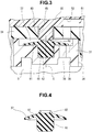
- the projection 82 is a ridge having a chevron sectional shape, and is formed into an annular shape when viewed from the axial direction of the shaft 42, as shown in Fig. 5 .
- the distal end of the projection 82 is pressed by the distal end face of the columnar body 83, and the projection 82 is deformed so as to buckle.
- the valve element 81 has a circular shape when viewed from the axial direction of the shaft 42.
- the outer diameter of the valve element 81 is smaller than the inner diameter of the circular concave portion 39 of the diaphragm holder 31.
- the valve element 81 is convex toward the diaphragm housing 32, and has a curved shape that forms part of a spherical surface.
- the valve element 81 is brought into tight contact with the seat surface 43 of the circular concave portion 39 by a predetermined pressing force.
- the valve element 81 comes into tight contact with the seat surface 43, the opening of the suction hole 38 is closed, and the suction passage 51 is closed.
- the suction valve 37 opens the suction passage 51 when the pressure in the pump chamber 48 is lower than the pressure in the suction hole 38 (suction passage 51). In addition, the suction valve 37 closes the suction passage 51 when the pressure in the pump chamber 48 is higher than the pressure in the suction hole 38 (suction passage 51). That is, the suction valve 37 is arranged in the suction passage 51, and opens and closes the suction passage 51.
- the rotary motion of the motor 12 is converted into a vertical motion by the driving mechanism 16, and the pump portions 25 of the diaphragm 24 repetitively contract and expand.
- the suction valve 37 opens, and the air in the housing space S is sucked into the pump chamber 48 via the suction passage 51.
- the discharge valve 46 opens, and the air in the pump chamber 48 is sent to the input-side space 56.
- the rapid discharge valve 71 is closed, and the air in the input-side space 56 flows to the output-side space 57 via the check valve 66, and is supplied to the outlet passage 61.
- the shaft 42 In the suction valve 37 of the diaphragm pump 11, the shaft 42 is sandwiched between the diaphragm holder 31 and the diaphragm housing 32 and held. At this time, when the shaft 42 is compressed in the axial direction, the valve element 81 is pressed against the seat surface 43 by a predetermined pressing force. Since it is therefore possible to assemble the suction valve 37 without using a knob portion, unlike an associated umbrella valve, the knob portion is unnecessary in the suction valve 37.
- the projection 82 When the shaft 42 is compressed, the projection 82 is elastically deformed.
- the magnitude of the pressing force that the shaft 42 receives from the diaphragm holder 31 and the diaphragm housing 32 increases/decreases within the range of tolerance of parts. If the pressing force is relatively large, the elastic deformation amount of the projection 82 increases. If the pressing force is relatively small, the elastic deformation amount of the projection 82 decreases.
- the force for pressing the valve element 81 against the seat surface 43 can easily be made moderate. This means that the accuracy of the position of the seal surface of the valve element 81 becomes high.
- the projection 82 of the suction valve 37 is a ridge having a chevron sectional shape, and is formed into an annular shape when viewed from the axial direction of the shaft 42. For this reason, the pressing force received from the columnar body 83 of the diaphragm housing 32 is readily transmitted to the circular valve element 81. As a result, since the valve element 81 is evenly in tight contact with the seat surface 43 all over the circumferential direction, sealing performance becomes high.
- the projection of the suction valve can be formed as shown in Fig. 6 .
- the same reference numerals as in Figs. 1 to 5 denote members similar to those described above, and a detailed description of the members will be omitted.
- a projection 91 of the suction valve 37 shown in Fig. 6 is formed into one chevron shape, and located on the same axis as the shaft 42.
- the projection 82 according to this embodiment is formed into a conical shape.
- the projection 82 having such a chevron shape is easily elastically deformed as compared to the projection 82 formed from an annular ridge as shown in Figs. 1 to 5 .
- the projection 91 shown in Fig. 6 is used, the projection 91 is elastically deformed even in a case in which the pressing force received from the columnar body 83 is relatively small. Hence, the position accuracy of the seal surface of the valve element 81 becomes high.
- the present invention is not limited to this. That is, the present invention can be applied to the discharge valve, or can be applied to both the suction valve and the discharge valve.
- the circular concave portion 39 is formed in the diaphragm housing 32.
- the bottom surface of the circular concave portion 39 forms the seat surface 43.
- the shaft hole 41 formed from a blind hole in which the lower end portion (second end portion) of the shaft 42 of the discharge valve 46 is inserted and the second groove 54 that forms part of the discharge passage 53 open to the seat surface 43.
- the columnar body 83 is formed at a portion facing the shaft 42 of the discharge valve 46.
- the diaphragm holder 31 presses the upper end portion (first end portion) of the shaft 42 inserted into the shaft hole 41 toward the lower end portion, and holds the shaft 42 together with the diaphragm housing 32.
- the valve element 81 of the discharge valve 46 thus comes into tight contact with the seat surface 43.
- the diaphragm housing 32 forms the "first housing member”
- the diaphragm holder 31 forms the "second housing member”.
- the present invention can also be applied to a pump that sucks and discharges a fluid such as another gas or a liquid.
Description
- The present invention relates to a diaphragm pump including an umbrella valve made of an elastic material.
- A diaphragm pump including an umbrella valve is disclosed in, for example,
Japanese Patent Laid-Open No. 2018-112127 Japanese Patent Laid-Open No. 2013-192639 - The diaphragm pump disclosed in
literature 1 includes a suction valve formed from an umbrella valve. The suction valve will be described with reference toFigs. 7 and 8 . As shown inFig. 7 , asuction valve 1 is attached to athrough hole 3 of ahousing member 2, and opens and closes asuction passage 5 formed in thehousing member 2. Thehousing member 2 forms apump chamber 8 together with apump portion 7 of adiaphragm 6. - The
suction valve 1 includes ashaft 4 inserted into the throughhole 3, and a plate-shaped valve element 9 integrally provided at one end portion of theshaft 4 located in thepump chamber 8. Astopper 4a having a diameter larger than the hole diameter of the throughhole 3 and aknob portion 4b projecting from thestopper 4a in the longitudinal direction are provided at the other end portion of theshaft 4 shown inFig. 7 . Before thesuction valve 1 is assembled in thehousing member 2, theknob portion 4b is formed long such that thestopper 4a is located in the middle part of theshaft 4, as shown inFig. 8 . - When the
shaft 4 is inserted into the throughhole 3, and theknob portion 4b is picked up and pulled such that thestopper 4a projects from thehousing member 2, thesuction valve 1 is attached to thehousing member 2. After that, as shown inFig. 7 , theknob portion 4b is cut near thestopper 4a. In a state in which thesuction valve 1 is attached to thehousing member 2, theshaft 4 pulls thevalve element 9 and thestopper 4a, and thevalve element 9 is pressed against aseat surface 2a of thehousing member 2 by a predetermined pressing force. Note thatFig. 7 illustrates thesuction valve 1 in an open state. - An umbrella valve disclosed in
literature 2 includes a shaft, and a plate-shaped valve element formed at the center portion of the shaft in the axial direction. The umbrella valve is arranged between two housing members. One end portion of the shaft is fitted in the shaft hole of one housing member, and the other end portion is fitted in the shaft hole of the other housing member. The umbrella valve is configured such that the valve element is in tight contact with the seat surface of one housing member in a state in which the two end portions of the shaft are fitted in the shaft holes. - In the diaphragm pump disclosed in
literature 1, since theknob portion 4b is cut after the umbrella valve is assembled in thehousing member 2, cutting operations increase, resulting in an increase in cost. On the other hand, if a structure in which theknob portion 4b is left without being cut is employed, other parts cannot be arranged at optimum positions to avoid interference with theknob portion 4b, and the diaphragm pump becomes bulky. Hence, the diaphragm pump disclosed inliterature 1 can hardly implement both cost reduction and size reduction because of theknob portion 4b of the umbrella valve. - The umbrella valve disclosed in
literature 2 can easily implement cost reduction and size reduction because theknob portion 4b is not necessary. In this umbrella valve, however, the position of the valve element in the axial direction of the shaft is hard to be constant because of the manufacturing error of the shaft or the shaft holes of the housing members, and the accuracy of the position of the seal surface is low. For this reason, the force for pressing the valve element against the seat surface is not constant, and the quality varies.
Further,JP 2008 180171 A independent claim 1. - It is an object of the present invention to implement an umbrella valve in which the accuracy of the position of a seal surface is high and provide a diaphragm pump capable of implementing cost reduction and size reduction.
- In order to achieve the object, according to the present invention, there is provided a diaphragm pump comprising a diaphragm including a pump portion, a pump housing configured to store the diaphragm and form a pump chamber together with the pump portion, a suction passage through which a fluid flows to the pump chamber when the pump chamber expands, a discharge passage through which a fluid discharged from the pump chamber flows when the pump chamber contracts, a suction valve arranged in the suction passage and configured to open and close the suction passage, and a discharge valve arranged in the discharge passage and configured to open and close the discharge passage, wherein at least one valve of the suction valve and the discharge valve is made of an elastic material, and includes a shaft including a first end portion and a second end portion, and a plate-shaped valve element extending from the first end portion of the shaft in a direction orthogonal to an axis of the shaft, the pump housing includes a first housing member including a shaft hole formed from a blind hole in which the second end portion of the shaft is inserted, and a seat surface to which one of part of the suction passage and part of the discharge passage opens, and a second housing member configured to press the first end portion of the shaft inserted into the shaft hole toward the second end portion and hold the shaft together with the first housing member, the first end portion of the shaft includes a projection projecting toward the second housing member, and the valve element is formed to come into tight contact with the seat surface when the shaft is sandwiched between the first housing member and the second housing member, and the second housing member includes a columnar body facing the shaft, and a total length of the shaft including the projection is slightly longer than an interval between a bottom of the shaft hole and a distal end of the columnar body in a completed state of the diaphragm pump.
-
-
Fig. 1 is a sectional view of a diaphragm pump according to an embodiment of the present invention; -
Fig. 2 is an enlarged sectional view of a valve element; -
Fig. 3 is an enlarged sectional view of a main part; -
Fig. 4 is a sectional view of a suction valve; -
Fig. 5 is a plan view of the suction valve viewed from an axial direction; -
Fig. 6 is a sectional view showing a modification of a projection; -
Fig. 7 is a sectional view showing part of an associated diaphragm pump; and -
Fig. 8 is a sectional view of an associated umbrella valve. - A diaphragm according to an embodiment of the present invention will now be described in detail with reference to
Figs. 1 to 6 . - A
diaphragm pump 11 shown inFig. 1 is attached to amotor 12 located at the lowermost position inFig. 1 . Thediaphragm pump 11 is driven by themotor 12 and operates. Thediaphragm pump 11 according to this embodiment is a pump that sucks and discharges air. Thediaphragm pump 11 includes adriving unit 13 fixed to themotor 12, and avalve portion 14 attached to thedriving unit 13. - The
driving unit 13 includes adriving unit housing 15 fixed to themotor 12, and adriving mechanism 16 stored in thehousing 15. Thehousing 15 is formed into a bottomed cylindrical shape, and thedriving mechanism 16 fixed to themotor 12 byfixing bolts 17 includes acrank body 19 attached to a rotatingshaft 18 of themotor 12, adriving body 21 connected to thecrank body 19 via adriving shaft 20, and the like. - The driving shaft 20 tilts in a predetermined direction with respect to the rotating
shaft 18. Thedriving body 21 includes acolumnar shaft portion 22 rotatably supported by thedriving shaft 20, and a plurality ofarm portions 23 projecting outward from theshaft portion 22 in the radial direction. Thearm portions 23 are provided forpump portions 25 of adiaphragm 24 to be described later, respectively, and radially extend outward from theshaft portion 22 in the radial direction. A throughhole 23a is formed in eacharm portion 23. A connectingpiece 26 of thediaphragm 24 is inserted into the throughhole 23a. The connectingpiece 26 extends through thearm portion 23 and is fixed to thearm portions 23 in this state. - According to the
driving mechanism 16, when thecrank body 19 and thedriving shaft 20 rotate together with the rotatingshaft 18 of themotor 12, thedriving body 21 swings, and thepump portions 25 of thediaphragm 24 repetitively contract and expand. - The
valve portion 14 includes adiaphragm holder 31 attached to the opening portion of the above-describeddriving unit housing 15, thediaphragm 24 arranged on thediaphragm holder 31, adiaphragm housing 32 attached to thediaphragm holder 31 in a state in which thediaphragm 24 is sandwiched between thediaphragm housing 32 and thediaphragm holder 31, apartition 33 arranged on thediaphragm housing 32, acover 34 attached to thediaphragm housing 32 via thepartition 33, and the like. - The
diaphragm holder 31, the diaphragm housing 32, and thecover 34 are each formed into a circular shape when viewed from the axial direction of themotor 12. In this embodiment, thediaphragm holder 31, the diaphragm housing 32, thecover 34, and the above-describeddriving unit housing 15 form apump housing 35. Thepump housing 35 stores the above-described members including thediaphragm 24. - The
diaphragm holder 31 is formed into a disc shape connectable to thedriving unit housing 15, and includes a plurality of through holes, as shown inFig. 2 . The through holes includecylinder holes 36 for the pump portions, in which thepump portions 25 of thediaphragm 24 are inserted, and asuction hole 38 to be opened and closed by asuction valve 37. Thecylinder holes 36 and thesuction hole 38 open to a housing space S surrounded by thedriving unit housing 15 and thediaphragm holder 31. - The
suction hole 38 forms part of asuction passage 51 to be described later, and makes the housing space S communicate with a circularconcave portion 39 formed at the center portion of thediaphragm holder 31. Ashaft hole 41 formed by a blind hole is formed at the center portion of the circularconcave portion 39. Ashaft 42 of thesuction valve 37 is fitted in theshaft hole 41. The structure of thesuction valve 37 will be described later. The bottom surface of the circularconcave portion 39 is formed flat to form aseat surface 43. Thesuction hole 38 and theshaft hole 41 open to theseat surface 43. - The
diaphragm 24 is sandwiched between thediaphragm holder 31 and thediaphragm housing 32 and held. Thediaphragm 24 includes the plurality of cup-shapedpump portions 25 that open toward thediaphragm housing 32, a plurality of first throughholes 44 located on the center side of thediaphragm holder 31 with respect to thepump portions 25 and provided for thepump portions 25, respectively, a second throughhole 45 located at the center portion of thediaphragm holder 31, a plurality ofdischarge valves 46 and a plurality of throughholes 47, which are located on the outer periphery side of thediaphragm holder 31 with respect to thepump portions 25 and provided for thepump portions 25, respectively, and the like. - The
pump portions 25 are arranged at positions that divide thediaphragm 24 into a plurality of parts in the circumferential direction of thediaphragm holder 31. Thepump portions 25 are inserted into the cylinder holes 36 formed in thediaphragm holder 31. The opening portions of thepump portions 25 are closed by thediaphragm housing 32. Apump chamber 48 is formed between eachpump portion 25 and thediaphragm housing 32. That is, thepump housing 35 including thediaphragm housing 32 forms thepump chambers 48 together with thepump portions 25. Apiston 49 is provided on the bottom of eachpump portion 25 having a cup shape. Thepiston 49 is provided with the connectingpiece 26 that projects in a direction opposite to thepump chamber 48. The connectingpiece 26 is connected to the drivingbody 21 of thedriving mechanism 16. - A
first groove 52 that forms part of asuction passage 51 and asecond groove 54 that forms part of adischarge passage 53 are formed in a portion of thediaphragm housing 32, which forms the wall of thepump chamber 48. Thefirst groove 52 extends from thepump chamber 48 toward the center of thediaphragm housing 32, and is connected to the first throughhole 44 of thediaphragm 24. - The
suction passage 51 is formed by thefirst groove 52, the first throughholes 44, thesuction hole 38 and the circularconcave portion 39 of thediaphragm holder 31, and the like. The circularconcave portion 39 is connected to all thesuction passages 51 provided of thepump chambers 48, although not illustrated. When thepump chamber 48 expands to open thesuction valve 37 to be described later, the air in the housing space S flows through thesuction passage 51 toward thepump chamber 48. - The
second groove 54 extends from thepump chamber 48 up to a position facing thedischarge valve 46 of thediaphragm 24. Thedischarge valve 46 is formed to close one end portion (downstream-side end portion) of thesecond groove 54 in the outer peripheral portion of thediaphragm housing 32. Thedischarge valve 46 opens thedischarge passage 53 when the pressure in thepump chamber 48 is higher than the pressure in the through hole 47 (discharge passage 53) of thediaphragm 24. In addition, thedischarge valve 46 closes thedischarge passage 53 when the pressure in thepump chamber 48 is lower than the pressure in the through hole 47 (discharge passage 53). The throughhole 47 of thediaphragm 24 is connected to one end portion of apassage hole 55 of thediaphragm housing 32. The other end portion of thepassage hole 55 is connected to an input-side space 56 formed between thediaphragm housing 32 and thepartition 33 to be described later. - The
discharge passage 53 is formed by thesecond groove 54, the throughhole 47, thepassage hole 55, and the like. Thedischarge valve 46 is arranged in thedischarge passage 53 and opens and closes thedischarge passage 53. When thepump chamber 48 contracts, thedischarge valve 46 opens, and air discharged from thepump chamber 48 flows through thedischarge passage 53. - The
partition 33 is sandwiched between thediaphragm housing 32 and thecover 34 and held. Thepartition 33 is formed into a plate shape by an elastic material such as a rubber material including synthetic rubber and partitions between thediaphragm housing 32 and thecover 34. The input-side space 56 is formed between thepartition 33 and thediaphragm housing 32, and an output-side space 57 is formed between thepartition 33 and thecover 34. - The input-
side space 56 and the output-side space 57 are divided by thepartition 33. The output-side space 57 is connected to anoutlet passage 61 provided in one side portion (the left side portion inFig. 2 ) of thecover 34, amain exhaust passage 62 provided in the other side portion of thecover 34, and asub-exhaust passage 63 provided at the center portion of thecover 34 via a communicating path (not shown). - A
cylindrical valve element 64 projecting toward thecover 34 is provided in one side portion (the left side portion inFig. 2 ) of thepartition 33. Thecylindrical valve element 64 forms acheck valve 66 together with acolumn 65 of thediaphragm housing 32. Thecheck valve 66 makes air in the input-side space 56 flow to the output-side space 57, and also prevents a backflow from the output-side space 57 to the input-side space 56. Thecolumn 65 forms the valve seat of thecheck valve 66. Thecylindrical valve element 64 has a cylindrical shape covering the outer peripheral surface of thecolumn 65. The projecting end of thecylindrical valve element 64 is separably in tight contact with the outer peripheral surface of thecolumn 65 all over the circumferential direction. The diameter of the base end portion of thecylindrical valve element 64 is larger than the diameter of thecolumn 65. The space between thecylindrical valve element 64 and thecolumn 65 is part of the input-side space 56. - The
partition 33 is provided with avalve element 72 of arapid discharge valve 71 and acircular hole 73 connected to thesub-exhaust passage 63. Therapid discharge valve 71 is formed by thevalve element 72, and avalve seat 74 to which themain exhaust passage 62 opens. Thevalve element 72 is moved by the pressure difference between the input-side space 56 and the output-side space 57, thereby opening and closing themain exhaust passage 62. Acolumnar projection 75 of thediaphragm housing 32 is inserted into thecircular hole 73. Thecolumnar projection 75 is spaced apart from the hole wall surface of thecircular hole 73 at a small gap. Hence, the input-side space 56 is opened to the atmosphere via the small gap between thecolumnar projection 75 and thecircular hole 73 and thesub-exhaust passage 63 of thecover 34. - The
suction valve 37 is an umbrella valve, and includes theshaft 42 and avalve element 81, as shown inFigs. 2 and3 . Theshaft 42 is formed into a columnar shape, and includes an upper end portion serving as a first end portion, and a lower end portion serving as a second end portion. The lower end portion of theshaft 42 is inserted into theshaft hole 41 of thediaphragm holder 31. The upper end portion of theshaft 42 is provided with aprojection 82 that projects toward thediaphragm housing 32. Thevalve element 81 is formed into a plate shape extending from the upper end portion of theshaft 42 in a direction orthogonal to an axis C (seeFig. 3 ). Thevalve element 81 according to this embodiment is formed into a so-called umbrella shape. Thesuction valve 37 is made of an elastic material such as a rubber material including synthetic rubber. For this reason, theshaft 42 including theprojection 82 and thevalve element 81 are integrally formed. - A
columnar body 83 is provided in a portion of thediaphragm housing 32 facing theshaft 42. Thecolumnar body 83 is formed into a columnar shape, inserted into the second throughhole 45 of thediaphragm 24, and is in contact with theprojection 82. The distal end face of thecolumnar body 83 in contact with theprojection 82 is formed flat. - The total length of the
shaft 42 including theprojection 82 is slightly longer than the interval between the bottom of theshaft hole 41 of thediaphragm holder 31 and the distal end of thecolumnar body 83 of thediaphragm housing 32 in a completed state of thediaphragm pump 11. For this reason, thediaphragm housing 32 including thecolumnar body 83 presses the upper end portion of theshaft 42 inserted into theshaft hole 41 toward the lower end portion, and holds theshaft 42 together with thediaphragm holder 31. In this embodiment, thediaphragm holder 31 forms a "first housing member", and thediaphragm housing 32 forms a "second housing member". - The
projection 82 according to this embodiment is a ridge having a chevron sectional shape, and is formed into an annular shape when viewed from the axial direction of theshaft 42, as shown inFig. 5 . In a state in which thesuction valve 37 is assembled between thediaphragm holder 31 and thediaphragm housing 32, the distal end of theprojection 82 is pressed by the distal end face of thecolumnar body 83, and theprojection 82 is deformed so as to buckle. - As shown in
Fig. 5 , thevalve element 81 has a circular shape when viewed from the axial direction of theshaft 42. The outer diameter of thevalve element 81 is smaller than the inner diameter of the circularconcave portion 39 of thediaphragm holder 31. - The
valve element 81 according to this embodiment is convex toward thediaphragm housing 32, and has a curved shape that forms part of a spherical surface. When theshaft 42 is sandwiched between thediaphragm holder 31 and thediaphragm housing 32, thevalve element 81 is brought into tight contact with theseat surface 43 of the circularconcave portion 39 by a predetermined pressing force. When thevalve element 81 comes into tight contact with theseat surface 43, the opening of thesuction hole 38 is closed, and thesuction passage 51 is closed. - The
suction valve 37 opens thesuction passage 51 when the pressure in thepump chamber 48 is lower than the pressure in the suction hole 38 (suction passage 51). In addition, thesuction valve 37 closes thesuction passage 51 when the pressure in thepump chamber 48 is higher than the pressure in the suction hole 38 (suction passage 51). That is, thesuction valve 37 is arranged in thesuction passage 51, and opens and closes thesuction passage 51. - In the thus configured
diaphragm pump 11, when themotor 12 is driven, the rotary motion of themotor 12 is converted into a vertical motion by thedriving mechanism 16, and thepump portions 25 of thediaphragm 24 repetitively contract and expand. When thepump portion 25 of thediaphragm 24 expands, thesuction valve 37 opens, and the air in the housing space S is sucked into thepump chamber 48 via thesuction passage 51. In addition, when thepump portion 25 of thediaphragm 24 contracts, thedischarge valve 46 opens, and the air in thepump chamber 48 is sent to the input-side space 56. When the pressure in the input-side space 56 rises, therapid discharge valve 71 is closed, and the air in the input-side space 56 flows to the output-side space 57 via thecheck valve 66, and is supplied to theoutlet passage 61. - When the
motor 12 stops, since the air in the input-side space 56 is discharged to the outside of the pump via thesub-exhaust passage 63, the pressure in the input-side space 56 lowers, and therapid discharge valve 71 opens accordingly. When therapid discharge valve 71 opens, the air in the output-side space 57, that is, the air in theoutlet passage 61 is discharged to the outside of the pump via themain exhaust passage 62. - In the
suction valve 37 of thediaphragm pump 11, theshaft 42 is sandwiched between thediaphragm holder 31 and thediaphragm housing 32 and held. At this time, when theshaft 42 is compressed in the axial direction, thevalve element 81 is pressed against theseat surface 43 by a predetermined pressing force. Since it is therefore possible to assemble thesuction valve 37 without using a knob portion, unlike an associated umbrella valve, the knob portion is unnecessary in thesuction valve 37. - When the
shaft 42 is compressed, theprojection 82 is elastically deformed. The magnitude of the pressing force that theshaft 42 receives from thediaphragm holder 31 and thediaphragm housing 32 increases/decreases within the range of tolerance of parts. If the pressing force is relatively large, the elastic deformation amount of theprojection 82 increases. If the pressing force is relatively small, the elastic deformation amount of theprojection 82 decreases. Hence, in thesuction valve 37, even if the dimensional accuracy of each part has a tolerance, the force for pressing thevalve element 81 against theseat surface 43 can easily be made moderate. This means that the accuracy of the position of the seal surface of thevalve element 81 becomes high. - Hence, according to this embodiment, it is possible to implement an umbrella valve in which the accuracy of the position of a seal surface is high and provide the
diaphragm pump 11 capable of implementing cost reduction and size reduction. - The
projection 82 of thesuction valve 37 according to this embodiment is a ridge having a chevron sectional shape, and is formed into an annular shape when viewed from the axial direction of theshaft 42. For this reason, the pressing force received from thecolumnar body 83 of thediaphragm housing 32 is readily transmitted to thecircular valve element 81. As a result, since thevalve element 81 is evenly in tight contact with theseat surface 43 all over the circumferential direction, sealing performance becomes high. - The projection of the suction valve can be formed as shown in
Fig. 6 . InFig. 6 , the same reference numerals as inFigs. 1 to 5 denote members similar to those described above, and a detailed description of the members will be omitted. - A
projection 91 of thesuction valve 37 shown inFig. 6 is formed into one chevron shape, and located on the same axis as theshaft 42. Theprojection 82 according to this embodiment is formed into a conical shape. Theprojection 82 having such a chevron shape is easily elastically deformed as compared to theprojection 82 formed from an annular ridge as shown inFigs. 1 to 5 . For this reason, when theprojection 91 shown inFig. 6 is used, theprojection 91 is elastically deformed even in a case in which the pressing force received from thecolumnar body 83 is relatively small. Hence, the position accuracy of the seal surface of thevalve element 81 becomes high. - In the above-described embodiment, an example in which the present invention is applied to the
suction valve 37 has been shown. However, the present invention is not limited to this. That is, the present invention can be applied to the discharge valve, or can be applied to both the suction valve and the discharge valve. - If the
discharge valve 46 having the same structure as thesuction valve 37 shown inFigs. 4 to 6 is used, the circularconcave portion 39 is formed in thediaphragm housing 32. The bottom surface of the circularconcave portion 39 forms theseat surface 43. Theshaft hole 41 formed from a blind hole in which the lower end portion (second end portion) of theshaft 42 of thedischarge valve 46 is inserted and thesecond groove 54 that forms part of thedischarge passage 53 open to theseat surface 43. Additionally, in thediaphragm holder 31, thecolumnar body 83 is formed at a portion facing theshaft 42 of thedischarge valve 46. Thediaphragm holder 31 presses the upper end portion (first end portion) of theshaft 42 inserted into theshaft hole 41 toward the lower end portion, and holds theshaft 42 together with thediaphragm housing 32. Thevalve element 81 of thedischarge valve 46 thus comes into tight contact with theseat surface 43. In this case, thediaphragm housing 32 forms the "first housing member", and thediaphragm holder 31 forms the "second housing member". - Additionally, in the above-described embodiment, an example in which the present invention is applied to the
diaphragm pump 11 for air has been shown. However, the present invention can also be applied to a pump that sucks and discharges a fluid such as another gas or a liquid.
Claims (3)
- A diaphragm pump (11) comprising:a diaphragm (24) including a pump portion (25);a pump housing (35) configured to store the diaphragm (24) and form a pump chamber (48) together with the pump portion (25);a suction passage (51) through which a fluid flows to the pump chamber (48) when the pump chamber (48) expands;a discharge passage (53) through which a fluid discharged from the pump chamber (48) flows when the pump chamber (48) contracts;a suction valve (37) arranged in the suction passage (51) and configured to open and close the suction passage (51); anda discharge valve (46) arranged in the discharge passage (53) and configured to open and close the discharge passage (53),wherein at least one valve of the suction valve (37) and the discharge valve (46)is made of an elastic material, andincludes a shaft (42) including a first end portion and a second end portion, and a plate-shaped valve element (81) extending from the first end portion of the shaft (42) in a direction orthogonal to an axis of the shaft (42),the pump housing (35) includes:a first housing member (31) including a shaft hole (41) formed from a blind hole in which the second end portion of the shaft (42) is inserted, and a seat surface (43) to which one of part of the suction passage (51) and part of the discharge passage (53) opens; anda second housing member (32) configured to press the first end portion of the shaft (42) inserted into the shaft hole (41) toward the second end portion and hold the shaft (42) together with the first housing member (31),the first end portion of the shaft (42) includes a projection (82, 91) projecting toward the second housing member (32),the valve element (81) is formed to come into tight contact with the seat surface (43) when the shaft (42) is sandwiched between the first housing member (31) and the second housing member (32), andthe second housing member (32) includes a columnar body (83) facing the shaft (42),characterized in thata total length of the shaft (42) including the projection (82) is slightly longer than an interval between a bottom of the shaft hole (41) and a distal end of the columnar body (83) in a completed state of the diaphragm pump (11).
- The diaphragm pump (11) according to claim 1, wherein the projection (82) is a ridge formed into an annular shape when viewed from a direction of the axis of the shaft (42) and having a chevron sectional shape.
- The diaphragm pump (11) according to claim 1, wherein the projection (91) is formed into a chevron shape.
Applications Claiming Priority (1)
| Application Number | Priority Date | Filing Date | Title |
|---|---|---|---|
| JP2018224701A JP7216367B2 (en) | 2018-11-30 | 2018-11-30 | Diaphragm pump |
Publications (2)
| Publication Number | Publication Date |
|---|---|
| EP3660309A1 EP3660309A1 (en) | 2020-06-03 |
| EP3660309B1 true EP3660309B1 (en) | 2021-08-18 |
Family
ID=68618008
Family Applications (1)
| Application Number | Title | Priority Date | Filing Date |
|---|---|---|---|
| EP19209884.6A Active EP3660309B1 (en) | 2018-11-30 | 2019-11-19 | Diaphragm pump |
Country Status (4)
| Country | Link |
|---|---|
| US (1) | US11225960B2 (en) |
| EP (1) | EP3660309B1 (en) |
| JP (1) | JP7216367B2 (en) |
| CN (1) | CN111255664B (en) |
Families Citing this family (1)
| Publication number | Priority date | Publication date | Assignee | Title |
|---|---|---|---|---|
| EP3879102B1 (en) * | 2020-03-13 | 2023-12-06 | Okenseiko Co., Ltd. | Diaphragm pump and pressure regulating apparatus |
Family Cites Families (12)
| Publication number | Priority date | Publication date | Assignee | Title |
|---|---|---|---|---|
| DE4439880C2 (en) * | 1994-11-08 | 1997-07-03 | Freudenberg Carl Fa | check valve |
| JP2003074724A (en) | 2001-09-03 | 2003-03-12 | Arai Pump Mfg Co Ltd | Check valve device |
| EP1308622B1 (en) | 2001-11-06 | 2013-12-18 | Oken Seiko Co., Ltd. | Diaphragm pump |
| CN200943569Y (en) | 2006-09-12 | 2007-09-05 | 陈健 | Valve for diaphragm pump |
| JP2008180171A (en) | 2007-01-25 | 2008-08-07 | Sharp Corp | Micro pump |
| TW200912139A (en) * | 2007-09-07 | 2009-03-16 | Chao-Fou Hsu | Diaphragm comprising an air discharge assembly with automatic air expelling function |
| JP5493961B2 (en) | 2009-02-24 | 2014-05-14 | 株式会社村田製作所 | Check valve, fluid device and pump |
| JP5171889B2 (en) | 2010-06-21 | 2013-03-27 | 本田技研工業株式会社 | Check valve |
| JP2013192639A (en) | 2012-03-16 | 2013-09-30 | Terumo Corp | Drug solution delivery device |
| WO2016153004A1 (en) | 2015-03-25 | 2016-09-29 | 株式会社タクミナ | Non-return valve and valve body |
| JP6858020B2 (en) | 2017-01-12 | 2021-04-14 | 応研精工株式会社 | Diaphragm pump |
| JP6876323B2 (en) | 2017-02-03 | 2021-05-26 | 応研精工株式会社 | Motorized pump |
-
2018
- 2018-11-30 JP JP2018224701A patent/JP7216367B2/en active Active
-
2019
- 2019-11-14 US US16/684,390 patent/US11225960B2/en active Active
- 2019-11-19 EP EP19209884.6A patent/EP3660309B1/en active Active
- 2019-11-27 CN CN201911189481.4A patent/CN111255664B/en active Active
Also Published As
| Publication number | Publication date |
|---|---|
| JP2020084953A (en) | 2020-06-04 |
| CN111255664B (en) | 2022-05-17 |
| EP3660309A1 (en) | 2020-06-03 |
| US11225960B2 (en) | 2022-01-18 |
| JP7216367B2 (en) | 2023-02-01 |
| CN111255664A (en) | 2020-06-09 |
| US20200173433A1 (en) | 2020-06-04 |
Similar Documents
| Publication | Publication Date | Title |
|---|---|---|
| EP2112377B1 (en) | Diaphragm pump | |
| EP3006738B1 (en) | Rapid-discharge-valve structural body and diaphragm pump | |
| KR20160021039A (en) | Diaphragm Pump Integrally Incuding Quick Discharge Valve Unit | |
| EP3660309B1 (en) | Diaphragm pump | |
| JP3300686B2 (en) | Multi-stage piston actuator | |
| JP6858020B2 (en) | Diaphragm pump | |
| EP3879102B1 (en) | Diaphragm pump and pressure regulating apparatus | |
| US3951046A (en) | Push rod and tappet assembly | |
| JPH0679883A (en) | Fluid transfer pump | |
| JP4181429B2 (en) | Piston pump | |
| JP6893021B2 (en) | Diaphragm pump | |
| JP2022113984A (en) | Diaphragm pump | |
| JP7449100B2 (en) | Diaphragm pump | |
| JP4092953B2 (en) | Small pump valve and pump using this valve | |
| JP2004360644A (en) | Scroll fluid machinery | |
| JP7382165B2 (en) | Mounting structure of diaphragm pump valve | |
| KR100486135B1 (en) | Direct acting safety valve and reciprocating piston combustion engine with this safety valve | |
| JP2004346886A (en) | Diaphragm pump | |
| JP3858134B2 (en) | Small pump | |
| EP4269797A1 (en) | Diaphragm pump | |
| JP7061367B2 (en) | Diaphragm pump | |
| JPWO2018037443A1 (en) | Multi-cylinder diaphragm pump | |
| JPS6329979Y2 (en) | ||
| JP2023147477A (en) | Quick exhaust valve-integrated diaphragm pump | |
| JP2545714Y2 (en) | Relief valve for pump |
Legal Events
| Date | Code | Title | Description |
|---|---|---|---|
| PUAI | Public reference made under article 153(3) epc to a published international application that has entered the european phase |
Free format text: ORIGINAL CODE: 0009012 |
|
| STAA | Information on the status of an ep patent application or granted ep patent |
Free format text: STATUS: THE APPLICATION HAS BEEN PUBLISHED |
|
| AK | Designated contracting states |
Kind code of ref document: A1 Designated state(s): AL AT BE BG CH CY CZ DE DK EE ES FI FR GB GR HR HU IE IS IT LI LT LU LV MC MK MT NL NO PL PT RO RS SE SI SK SM TR |
|
| AX | Request for extension of the european patent |
Extension state: BA ME |
|
| STAA | Information on the status of an ep patent application or granted ep patent |
Free format text: STATUS: REQUEST FOR EXAMINATION WAS MADE |
|
| 17P | Request for examination filed |
Effective date: 20201201 |
|
| RBV | Designated contracting states (corrected) |
Designated state(s): AL AT BE BG CH CY CZ DE DK EE ES FI FR GB GR HR HU IE IS IT LI LT LU LV MC MK MT NL NO PL PT RO RS SE SI SK SM TR |
|
| GRAP | Despatch of communication of intention to grant a patent |
Free format text: ORIGINAL CODE: EPIDOSNIGR1 |
|
| STAA | Information on the status of an ep patent application or granted ep patent |
Free format text: STATUS: GRANT OF PATENT IS INTENDED |
|
| RIC1 | Information provided on ipc code assigned before grant |
Ipc: F04B 39/14 20060101ALN20210415BHEP Ipc: F04B 39/12 20060101ALN20210415BHEP Ipc: F04B 53/10 20060101ALI20210415BHEP Ipc: F04B 45/04 20060101AFI20210415BHEP |
|
| INTG | Intention to grant announced |
Effective date: 20210510 |
|
| GRAS | Grant fee paid |
Free format text: ORIGINAL CODE: EPIDOSNIGR3 |
|
| GRAA | (expected) grant |
Free format text: ORIGINAL CODE: 0009210 |
|
| STAA | Information on the status of an ep patent application or granted ep patent |
Free format text: STATUS: THE PATENT HAS BEEN GRANTED |
|
| AK | Designated contracting states |
Kind code of ref document: B1 Designated state(s): AL AT BE BG CH CY CZ DE DK EE ES FI FR GB GR HR HU IE IS IT LI LT LU LV MC MK MT NL NO PL PT RO RS SE SI SK SM TR |
|
| REG | Reference to a national code |
Ref country code: GB Ref legal event code: FG4D |
|
| REG | Reference to a national code |
Ref country code: CH Ref legal event code: EP |
|
| REG | Reference to a national code |
Ref country code: DE Ref legal event code: R096 Ref document number: 602019006975 Country of ref document: DE |
|
| REG | Reference to a national code |
Ref country code: IE Ref legal event code: FG4D Ref country code: AT Ref legal event code: REF Ref document number: 1421877 Country of ref document: AT Kind code of ref document: T Effective date: 20210915 |
|
| REG | Reference to a national code |
Ref country code: LT Ref legal event code: MG9D |
|
| REG | Reference to a national code |
Ref country code: NL Ref legal event code: MP Effective date: 20210818 |
|
| REG | Reference to a national code |
Ref country code: AT Ref legal event code: MK05 Ref document number: 1421877 Country of ref document: AT Kind code of ref document: T Effective date: 20210818 |
|
| PG25 | Lapsed in a contracting state [announced via postgrant information from national office to epo] |
Ref country code: RS Free format text: LAPSE BECAUSE OF FAILURE TO SUBMIT A TRANSLATION OF THE DESCRIPTION OR TO PAY THE FEE WITHIN THE PRESCRIBED TIME-LIMIT Effective date: 20210818 Ref country code: SE Free format text: LAPSE BECAUSE OF FAILURE TO SUBMIT A TRANSLATION OF THE DESCRIPTION OR TO PAY THE FEE WITHIN THE PRESCRIBED TIME-LIMIT Effective date: 20210818 Ref country code: ES Free format text: LAPSE BECAUSE OF FAILURE TO SUBMIT A TRANSLATION OF THE DESCRIPTION OR TO PAY THE FEE WITHIN THE PRESCRIBED TIME-LIMIT Effective date: 20210818 Ref country code: HR Free format text: LAPSE BECAUSE OF FAILURE TO SUBMIT A TRANSLATION OF THE DESCRIPTION OR TO PAY THE FEE WITHIN THE PRESCRIBED TIME-LIMIT Effective date: 20210818 Ref country code: FI Free format text: LAPSE BECAUSE OF FAILURE TO SUBMIT A TRANSLATION OF THE DESCRIPTION OR TO PAY THE FEE WITHIN THE PRESCRIBED TIME-LIMIT Effective date: 20210818 Ref country code: PT Free format text: LAPSE BECAUSE OF FAILURE TO SUBMIT A TRANSLATION OF THE DESCRIPTION OR TO PAY THE FEE WITHIN THE PRESCRIBED TIME-LIMIT Effective date: 20211220 Ref country code: NO Free format text: LAPSE BECAUSE OF FAILURE TO SUBMIT A TRANSLATION OF THE DESCRIPTION OR TO PAY THE FEE WITHIN THE PRESCRIBED TIME-LIMIT Effective date: 20211118 Ref country code: LT Free format text: LAPSE BECAUSE OF FAILURE TO SUBMIT A TRANSLATION OF THE DESCRIPTION OR TO PAY THE FEE WITHIN THE PRESCRIBED TIME-LIMIT Effective date: 20210818 Ref country code: AT Free format text: LAPSE BECAUSE OF FAILURE TO SUBMIT A TRANSLATION OF THE DESCRIPTION OR TO PAY THE FEE WITHIN THE PRESCRIBED TIME-LIMIT Effective date: 20210818 Ref country code: BG Free format text: LAPSE BECAUSE OF FAILURE TO SUBMIT A TRANSLATION OF THE DESCRIPTION OR TO PAY THE FEE WITHIN THE PRESCRIBED TIME-LIMIT Effective date: 20211118 |
|
| PG25 | Lapsed in a contracting state [announced via postgrant information from national office to epo] |
Ref country code: PL Free format text: LAPSE BECAUSE OF FAILURE TO SUBMIT A TRANSLATION OF THE DESCRIPTION OR TO PAY THE FEE WITHIN THE PRESCRIBED TIME-LIMIT Effective date: 20210818 Ref country code: LV Free format text: LAPSE BECAUSE OF FAILURE TO SUBMIT A TRANSLATION OF THE DESCRIPTION OR TO PAY THE FEE WITHIN THE PRESCRIBED TIME-LIMIT Effective date: 20210818 Ref country code: GR Free format text: LAPSE BECAUSE OF FAILURE TO SUBMIT A TRANSLATION OF THE DESCRIPTION OR TO PAY THE FEE WITHIN THE PRESCRIBED TIME-LIMIT Effective date: 20211119 |
|
| PG25 | Lapsed in a contracting state [announced via postgrant information from national office to epo] |
Ref country code: NL Free format text: LAPSE BECAUSE OF FAILURE TO SUBMIT A TRANSLATION OF THE DESCRIPTION OR TO PAY THE FEE WITHIN THE PRESCRIBED TIME-LIMIT Effective date: 20210818 |
|
| PG25 | Lapsed in a contracting state [announced via postgrant information from national office to epo] |
Ref country code: DK Free format text: LAPSE BECAUSE OF FAILURE TO SUBMIT A TRANSLATION OF THE DESCRIPTION OR TO PAY THE FEE WITHIN THE PRESCRIBED TIME-LIMIT Effective date: 20210818 |
|
| REG | Reference to a national code |
Ref country code: DE Ref legal event code: R097 Ref document number: 602019006975 Country of ref document: DE |
|
| PG25 | Lapsed in a contracting state [announced via postgrant information from national office to epo] |
Ref country code: SM Free format text: LAPSE BECAUSE OF FAILURE TO SUBMIT A TRANSLATION OF THE DESCRIPTION OR TO PAY THE FEE WITHIN THE PRESCRIBED TIME-LIMIT Effective date: 20210818 Ref country code: SK Free format text: LAPSE BECAUSE OF FAILURE TO SUBMIT A TRANSLATION OF THE DESCRIPTION OR TO PAY THE FEE WITHIN THE PRESCRIBED TIME-LIMIT Effective date: 20210818 Ref country code: RO Free format text: LAPSE BECAUSE OF FAILURE TO SUBMIT A TRANSLATION OF THE DESCRIPTION OR TO PAY THE FEE WITHIN THE PRESCRIBED TIME-LIMIT Effective date: 20210818 Ref country code: EE Free format text: LAPSE BECAUSE OF FAILURE TO SUBMIT A TRANSLATION OF THE DESCRIPTION OR TO PAY THE FEE WITHIN THE PRESCRIBED TIME-LIMIT Effective date: 20210818 Ref country code: CZ Free format text: LAPSE BECAUSE OF FAILURE TO SUBMIT A TRANSLATION OF THE DESCRIPTION OR TO PAY THE FEE WITHIN THE PRESCRIBED TIME-LIMIT Effective date: 20210818 Ref country code: AL Free format text: LAPSE BECAUSE OF FAILURE TO SUBMIT A TRANSLATION OF THE DESCRIPTION OR TO PAY THE FEE WITHIN THE PRESCRIBED TIME-LIMIT Effective date: 20210818 |
|
| PLBE | No opposition filed within time limit |
Free format text: ORIGINAL CODE: 0009261 |
|
| STAA | Information on the status of an ep patent application or granted ep patent |
Free format text: STATUS: NO OPPOSITION FILED WITHIN TIME LIMIT |
|
| PG25 | Lapsed in a contracting state [announced via postgrant information from national office to epo] |
Ref country code: MC Free format text: LAPSE BECAUSE OF FAILURE TO SUBMIT A TRANSLATION OF THE DESCRIPTION OR TO PAY THE FEE WITHIN THE PRESCRIBED TIME-LIMIT Effective date: 20210818 |
|
| 26N | No opposition filed |
Effective date: 20220519 |
|
| PG25 | Lapsed in a contracting state [announced via postgrant information from national office to epo] |
Ref country code: IT Free format text: LAPSE BECAUSE OF FAILURE TO SUBMIT A TRANSLATION OF THE DESCRIPTION OR TO PAY THE FEE WITHIN THE PRESCRIBED TIME-LIMIT Effective date: 20210818 Ref country code: BE Free format text: LAPSE BECAUSE OF NON-PAYMENT OF DUE FEES Effective date: 20211130 Ref country code: LU Free format text: LAPSE BECAUSE OF NON-PAYMENT OF DUE FEES Effective date: 20211119 |
|
| REG | Reference to a national code |
Ref country code: BE Ref legal event code: MM Effective date: 20211130 |
|
| PG25 | Lapsed in a contracting state [announced via postgrant information from national office to epo] |
Ref country code: SI Free format text: LAPSE BECAUSE OF FAILURE TO SUBMIT A TRANSLATION OF THE DESCRIPTION OR TO PAY THE FEE WITHIN THE PRESCRIBED TIME-LIMIT Effective date: 20210818 |
|
| PG25 | Lapsed in a contracting state [announced via postgrant information from national office to epo] |
Ref country code: IE Free format text: LAPSE BECAUSE OF NON-PAYMENT OF DUE FEES Effective date: 20211119 |
|
| PG25 | Lapsed in a contracting state [announced via postgrant information from national office to epo] |
Ref country code: CY Free format text: LAPSE BECAUSE OF FAILURE TO SUBMIT A TRANSLATION OF THE DESCRIPTION OR TO PAY THE FEE WITHIN THE PRESCRIBED TIME-LIMIT Effective date: 20210818 |
|
| REG | Reference to a national code |
Ref country code: CH Ref legal event code: PL |
|
| PG25 | Lapsed in a contracting state [announced via postgrant information from national office to epo] |
Ref country code: LI Free format text: LAPSE BECAUSE OF NON-PAYMENT OF DUE FEES Effective date: 20221130 Ref country code: HU Free format text: LAPSE BECAUSE OF FAILURE TO SUBMIT A TRANSLATION OF THE DESCRIPTION OR TO PAY THE FEE WITHIN THE PRESCRIBED TIME-LIMIT; INVALID AB INITIO Effective date: 20191119 Ref country code: CH Free format text: LAPSE BECAUSE OF NON-PAYMENT OF DUE FEES Effective date: 20221130 |
|
| PGFP | Annual fee paid to national office [announced via postgrant information from national office to epo] |
Ref country code: GB Payment date: 20231127 Year of fee payment: 5 |
|
| PGFP | Annual fee paid to national office [announced via postgrant information from national office to epo] |
Ref country code: FR Payment date: 20231006 Year of fee payment: 5 Ref country code: DE Payment date: 20231120 Year of fee payment: 5 |