EP3659629A2 - Diffusor von ätherischen ölen - Google Patents
Diffusor von ätherischen ölen Download PDFInfo
- Publication number
- EP3659629A2 EP3659629A2 EP19212877.5A EP19212877A EP3659629A2 EP 3659629 A2 EP3659629 A2 EP 3659629A2 EP 19212877 A EP19212877 A EP 19212877A EP 3659629 A2 EP3659629 A2 EP 3659629A2
- Authority
- EP
- European Patent Office
- Prior art keywords
- diffuser
- closed position
- housing
- bottle
- valve
- Prior art date
- Legal status (The legal status is an assumption and is not a legal conclusion. Google has not performed a legal analysis and makes no representation as to the accuracy of the status listed.)
- Granted
Links
Images



Classifications
-
- A—HUMAN NECESSITIES
- A61—MEDICAL OR VETERINARY SCIENCE; HYGIENE
- A61L—METHODS OR APPARATUS FOR STERILISING MATERIALS OR OBJECTS IN GENERAL; DISINFECTION, STERILISATION OR DEODORISATION OF AIR; CHEMICAL ASPECTS OF BANDAGES, DRESSINGS, ABSORBENT PADS OR SURGICAL ARTICLES; MATERIALS FOR BANDAGES, DRESSINGS, ABSORBENT PADS OR SURGICAL ARTICLES
- A61L9/00—Disinfection, sterilisation or deodorisation of air
- A61L9/015—Disinfection, sterilisation or deodorisation of air using gaseous or vaporous substances, e.g. ozone
- A61L9/04—Disinfection, sterilisation or deodorisation of air using gaseous or vaporous substances, e.g. ozone using substances evaporated in the air without heating
- A61L9/12—Apparatus, e.g. holders, therefor
Definitions
- the present application relates to the technical field of essential oil diffusers and more particularly electric essential oil diffusers.
- diffusers with an open reservoir of essential oil (mixed or not with water) filled manually by the user and diffusers with housing for receiving an oil bottle. essential.
- essential oil mixed or not with water
- the latter type of diffusers comprises a housing on which a male plug or a USB connector are arranged and the receptacle for receiving the bottle, which makes them compact and practical to use.
- a bottle of essential oil is fitted with a dropper.
- the dropper must generally be removed to allow the insertion inside the bottle of an absorbent element causing the oil to rise by capillary action. Having to remove the dropper has the disadvantage of getting the user's hands dirty.
- the essential oil bottle is placed upside down to allow the essential oil to flow by gravitation into a tank.
- it is necessary to empty the diffuser reservoir again in the bottle at the risk of very often spilling essential oil, for example on the hands or on a support, which requires cleaning. of the hands and / or the support and depending on the essential oil used, cleaning must be carried out quickly to avoid damaging the hands and / or damaging the support.
- one of the objectives of the present invention is to remedy at least one of the drawbacks of the state of the art.
- the drip cutter can be accommodated under the fixing ring.
- the circular base can be extended at its periphery by a skirt extending substantially perpendicular to the circular base, the skirt and the circular base forming housing for the movable part and the return.
- the return can be a spring arranged so as to force the movable base against the circular base thus obstructing the second orifice.
- the diffuser may further comprise a spring housing disposed under the moving part.
- the spring housing can be formed of at least three coplanar arms extending from a center and as many fixing fingers, each of the fixing fingers extending one of the three coplanar arms perpendicular to the common plane of the coplanar arms; and the skirt can be provided with as many orifices as there are fixing fingers and each receiving one of the fixing fingers for fixing the spring housing to the skirt.
- the diffuser may further include a connector to a power source.
- the connector to a power source can be a male plug or a USB connector.
- the diffuser may include a photovoltaic module for the electrical supply of the diffuser.
- the disperser can be a nebulizer or a piezoelectric pellet.
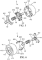
- An essential oil diffuser 10 according to the present invention is described below with reference to Figures 1 to 7 .
- the spatial orientations are given relative to the normal position of use of the diffuser 10 .
- the essential oil diffuser 10 comprises a box 1 , a housing 2 for receiving a bottle 9 of essential oil, a connector 3 to a power source, a reservoir 5 and a drip cutter 4 .
- the receiving housing 2 and the connector 3 are provided on the housing 1 and the drip cutter 4 in the receiving housing 2 or just below it.
- the receiving housing 2 comprises a fixing ring 21 for the bottle 9 .
- the drip cutter 4 may include a valve, an actuator for moving the valve and thus controlling the valve from a closed position corresponding to the closed position of the drip cutter 4 to an open position corresponding to the open position of the drip cutter 4 , and a reminder to move the valve from the open position to the closed position.
- the fixing ring 21 and the drip cutter 4 are configured so that when the neck of the bottle 9 is fixed to the fixing ring 21 , the neck forces the actuator to move the valve from the position closed in the open position and when the neck of the bottle 9 is removed from the fixing ring 21 , the reminder returns the valve to its closed position.
- the drip cutter 4 can be formed from a moving part 42 , and a circular base 41 .
- the movable part 42 comprises a movable base 421 from which extend substantially perpendicular thereto one or more actuating fingers 422 forming the actuator, possibly after a coplanar extension 4221 to the movable base 421 .
- the mobile base 421 has a discoid shape.
- Each of the actuating fingers 422 has a first extension part 4221 collinear with the mobile base 421 and a projecting part 4222 extending perpendicular to the discoid surface of the mobile base 421.
- the width of the extension part 4221 and that of the protruding part 4222 are equal.
- the projecting part 4222 preferably has a rounded free end.
- each actuating finger 422 extends radially from the discoid mobile base 421 . If there is a plurality of actuating fingers 422 , they are preferably distributed angularly in a homogeneous manner around the mobile base 421 .
- the circular base 41 comprises one or more first orifices 411 , the number of first orifices 411 being equal to the number of actuating fingers 422 , each finger passing through a first orifice 411 in the closed position of the valve.
- the circular base 41 also comprises a second orifice 412 disposed opposite the movable base 421 so as to be obstructed by the latter and thus forming the valve.
- the size of the mobile base 421 is slightly larger than the size of the second orifice 412 .
- the mobile base 421 and the second orifice 412 have the same geometry.
- the circular base 41 has a circular annular shape with the second circular orifice 412 in the center and the first orifices 411 placed on the ring 413 and having the same angular distribution as the actuating fingers 422.
- the base circular 41 has a chamfer 4121 on its inner edge surrounding the second orifice 412 and the movable base 421 also has a chamfer 4211 on its outer edge thus facilitating adjustment from one to the other to form the closed position of the cutter drops 4 .
- the size and shape of the first orifices 411 are adapted to that of the actuating fingers 422 and in particular of their projecting parts 4222 for displacement by translation of the projecting parts 4222 through the first orifices 411 without play.
- the first orifices 411 can also serve as a guide for moving the actuating fingers 422 .
- the circular base 41 can be extended at its periphery with a skirt 414 extending substantially perpendicularly to the circular base 41 , the skirt 414 and the circular base 41 forming housing for the moving part 42 and the return 44 .
- the skirt 414 is preferably cylindrical, always preferably with a circular base 41 .
- the return 44 is preferably a spring arranged so as to force the movable base 421 against the circular base 41 thus obstructing the second orifice 412 .
- the spring 44 is preferably a cylindrical helical spring disposed centrally relative to the movable base 421 .
- the reminder 44 can be any means allowing the valve to return to its closed position.
- the diffuser 10 may further comprise a spring housing 43 disposed under the moving part 42 .
- the spring housing 43 serves in particular as a fixed stop for the spring 44 .
- the spring housing 43 is formed of at least three coplanar arms 432 extending from a center 431 (preferably distributed angularly in a regular manner) and as many fixing fingers 433 , each of the fingers fixing 433 extending one of the three coplanar arms 432 perpendicular to the common plane of the coplanar arms 432 .
- the skirt 414 is advantageously provided with as much fixing holes 415 that there are fixing fingers 433.
- Each of the fixing holes 415 receives one of the fixing fingers 433 for fixing the spring housing 43 to the skirt 414 .
- the skirt 414 can comprise as many notches 416 as there are fixing fingers 433 of the spring housing 43 for their indexing. The notches 416 are produced in particular on the free circular edge of the skirt 414 .
- the fixing ring 21 of the receiving housing 2 has in particular a thread for fixing by screwing the neck of the bottle 9 of essential oil.
- the height of the fixing ring 21 can correspond to the height of the neck of the bottle 9 or smaller.
- the threaded part of the neck generally has a height of between 8 and 15 mm, more generally between 11 and 12 mm.
- the height of the fixing ring 21 is between 8 and 15 mm, preferably between 11 and 12 mm.
- the fixing ring 21 is arranged just above the drip cutter 4 , in particular so that the actuating fingers 422 extend at least partially in the fixing ring 21 so as to be actuable by the neck of the bottle 9.
- the receiving housing 2 can also include an open chamber 22 in which the body of the bottle 9 is accommodatable.
- the open chamber 22 is arranged above the fixing ring 21 .
- the size of the open chamber 22 is chosen so as to accommodate at least one 5 ml bottle 9 , preferably up to 10 ml, up to 15 ml, up to 30 ml.
- This open chamber 22 is preferably made in the housing 1 .
- the reservoir 5 is preferably placed under the drip cutter 4 .
- the capacity of the reservoir 5 is preferably less than 5 ml, preferably less than 3 ml, always preferably between 1 ml and 2 ml. But in general, its capacity does not matter, it is enough that it is sufficient to allow the diffusion of the essential oil according to the chosen disperser. Indeed, the fact that the bottle 9 of essential oil remains attached to the diffuser 10 ensures the supply of the reservoir 5 with oil until the bottle 9 is empty or almost empty (the dropper does not always allow completely empty the bottle 9 ).
- the reservoir 5 is fluidly connected to a diffusion outlet 13 produced in the housing 1 .
- This diffusion outlet 13 allows the oil to come out of the diffuser 10 and to spread in the room where it is placed.
- the disperser 6 can be a nebulizer or a piezoelectric pellet. It is placed in the tank 5 .
- Connector 3 to a power source can be a male plug or a USB connector.
- a male plug this is preferably symmetrical in the plane formed by the phase terminal and the neutral terminal in order to allow the correct position of the diffuser 10 according to the orientation of the female sockets.
- the essential oil diffuser 10 can comprise a photovoltaic module (mini solar panel) allowing the electrical supply of the diffuser by solar energy.
- the diffuser 10 includes both the connector 3 and the photovoltaic module, this allows both to use solar energy when it is available or another source of power when solar energy is not available for example in overcast weather, rainy weather or at night.
- the connector 3 and the reception housing 2 are arranged on the same side of the housing 1 , called the rear of the housing 11 .
- the front of the case 12 can be used to partially hide the bottle 9 and the plug and also to carry a decorative element.
- the diffuser 10 includes, like any electric diffuser, electronics (not illustrated in the figures) for controlling the diffusion of the essential oil. This electronics is placed in the housing 1 and electrically connected to the power connector 3 .
- the diffuser 10 may further comprise a switch 14 comprising at least two positions: on and off.
- the switch 14 comprises more than two positions, one for stopping and two for two different operating modes of the diffuser 10 .
- the switch 14 is a push button produced on the housing 1 , advantageously at the front of the housing 12 .
- the diffuser 10 may also include an operating indicator 15 to indicate to the user that he is on.
- This indicator 15 is preferably a light-emitting diode which is lit when the diffuser 10 is in operation.
- the indicator 15 is preferably placed on the housing 1 , advantageously on the front part of the housing 1 so as to remain visible when the diffuser 10 is connected by the connector 3 to a power source.
- the indicator 15 may further include an optical diffuser coupled to the LED, the LED illuminating the optical diffuser and the latter propagating the light emitted by the LED so that what is visible to the user has a larger size.
- the indicator 15 can be combined with the switch.
- the operating mode is described below with reference to a diffuser 10 comprising all of the characteristics described above. In embodiments without any of the features, the description of the corresponding operation can be simply ignored.
- the drip cutter 4 is by default in the closed position, in particular the reminder 44 forces the valve into its closed position, for example the spring 44 exerts a force against the mobile base 421 which then obstructs the second orifice 412 of the circular base 41 .
- the movement of the mobile base 421 is limited by the circular base 41 itself, for example by the annular part 413 thereof. In this position, the actuating fingers 422 protrude completely out of the first orifices 411 .
- a bottle 9 of essential oil is then fixed to the diffuser 10 by the reception housing 2 , for example by screwing the neck of the bottle 9 to the fixing ring 21 of the reception housing 2 .
- the neck of the bottle 9 comes into contact with the actuator and forces the actuator to drive the valve into its open position, for example by pushing the actuating fingers 422 which transmit the force exerted by the neck of the bottle 9 to the movable base 421 thus opening the valve.
- the essential oil can then flow from the bottle 9 , still provided with its dropper, to the tank 5 .
- the diffuser 10 is then connected to a power source via the connector 3 , for example by inserting the male plug into an AC outlet. It should be noted that this step can be carried out before the fixing of the bottle 9 , although carrying it out after the fixing makes the fixing easier.
- the diffuser 10 In the case where the diffuser 10 does not include a switch, the diffuser 10 begins to operate as soon as it is connected. In the case where the diffuser 10 has a switch 14 , it does not start to function until the user puts the switch 14 in the on position.
- the essential oil is then diffused thanks to the disperser 6 .
- the disperser 6 nebulizes or mistes the essential oil which emerges through the diffusion outlet 13 .
- the diffuser 10 During the operation of the diffuser 10 and if the latter has an indicator 15, this is actuated, for example the LED is lit. The user can then know that the diffuser 10 is in operation by seeing the LED or the optical diffuser.
- the user disconnects the diffuser 10 and / or puts the switch 14 in the stop position according to the applicable case.
- the disperser 6 stops diffusing the essential oil.
- the user can then remove the bottle 9 .
- the reminder 44 returns the valve to its closed position, for example the spring 44 pushes the movable base 421 against the circular base 41.
- the essential oil contained in the reservoir 5 cannot therefore leave it by the receiving housing 2 which avoids dirtying the hands and / or a support by handling the diffuser 10 and the bottle 9 . Furthermore, there is no need to empty the reservoir 5 of the diffuser 10 in the bottle 9 .
Landscapes
- Health & Medical Sciences (AREA)
- Epidemiology (AREA)
- Life Sciences & Earth Sciences (AREA)
- Animal Behavior & Ethology (AREA)
- General Health & Medical Sciences (AREA)
- Public Health (AREA)
- Veterinary Medicine (AREA)
- Dry Shavers And Clippers (AREA)
- Crushing And Pulverization Processes (AREA)
- Containers And Packaging Bodies Having A Special Means To Remove Contents (AREA)
- Infusion, Injection, And Reservoir Apparatuses (AREA)
Applications Claiming Priority (1)
| Application Number | Priority Date | Filing Date | Title |
|---|---|---|---|
| FR1872159A FR3089125B1 (fr) | 2018-11-30 | 2018-11-30 | Diffuseur d’huile essentielle |
Publications (3)
| Publication Number | Publication Date |
|---|---|
| EP3659629A2 true EP3659629A2 (de) | 2020-06-03 |
| EP3659629A3 EP3659629A3 (de) | 2020-07-29 |
| EP3659629B1 EP3659629B1 (de) | 2023-06-07 |
Family
ID=65951775
Family Applications (1)
| Application Number | Title | Priority Date | Filing Date |
|---|---|---|---|
| EP19212877.5A Active EP3659629B1 (de) | 2018-11-30 | 2019-12-02 | Diffusor von ätherischen ölen |
Country Status (2)
| Country | Link |
|---|---|
| EP (1) | EP3659629B1 (de) |
| FR (1) | FR3089125B1 (de) |
Family Cites Families (3)
| Publication number | Priority date | Publication date | Assignee | Title |
|---|---|---|---|---|
| US20080290120A1 (en) * | 2007-05-25 | 2008-11-27 | Helf Thomas A | Actuator cap for a spray device |
| US8170405B2 (en) * | 2009-03-27 | 2012-05-01 | Harris Robert M | Multipurpose cartridge-based liquid dispensing air freshener system |
| FR2961698A1 (fr) * | 2010-06-28 | 2011-12-30 | Jean Pierre Vollot | La presente invention concerne un ensemble de dispositifs pour diffuser des senteurs d'ambiance, alimentaires ou assainissantes. |
-
2018
- 2018-11-30 FR FR1872159A patent/FR3089125B1/fr active Active
-
2019
- 2019-12-02 EP EP19212877.5A patent/EP3659629B1/de active Active
Also Published As
| Publication number | Publication date |
|---|---|
| FR3089125B1 (fr) | 2021-06-04 |
| EP3659629B1 (de) | 2023-06-07 |
| EP3659629A3 (de) | 2020-07-29 |
| FR3089125A1 (fr) | 2020-06-05 |
Similar Documents
| Publication | Publication Date | Title |
|---|---|---|
| EP2739546B1 (de) | Flüssigmaterialspender | |
| EP2707305B1 (de) | Flüssigproduktspender | |
| EP1570205B1 (de) | Mobile beleuchtungseinrichtung mit einem rohrförmigen gehäuse | |
| EP2969241B1 (de) | Nachfüllbare vorrichtung zur verpackung und abgabe eines flüssigen produkts | |
| EP0486355A1 (de) | Abgabevorrichtung für ein flüssiges bis pastöses Erzeugnis und Halterung für eine solche Abgabevorrichtung | |
| CA3114042A1 (fr) | Accessoire de type sabre laser | |
| FR2814139A1 (fr) | Module de commande et d'alimentation electrique integre pour usage a bord d'une bicyclette | |
| FR2967830A1 (fr) | Prise electrique comportant un obturateur | |
| EP2916964A1 (de) | Flüssigproduktspender | |
| FR2761281A1 (fr) | Dispositif de pulverisation de produit fluide, tel q'un bidose | |
| FR3000944A1 (fr) | Distributeur de produit fluide. | |
| EP3057463B1 (de) | Reservoir, bauteilreservoir und sortiment von solchen produkten | |
| FR2851027A1 (fr) | Lampe electrique portative equipee d'un filtre colore basculant | |
| EP3659629B1 (de) | Diffusor von ätherischen ölen | |
| FR2843001A1 (fr) | Distributeur de parfum a cartouche perforable | |
| WO2012035247A1 (fr) | Dispositif de rangement pour liquide de nettoyage de machine a cafe | |
| EP2554893B1 (de) | LED-Lampenvorrichtung und automatisiertes Herstellungsverfahren dieser Vorrichtung | |
| FR2755497A1 (fr) | Lampe d'eclairage electrique portative a barillet rotatif | |
| EP3276259B1 (de) | Wasserdichter scheinwerfer und sein herstellungsverfahren | |
| FR2597595A3 (fr) | Dispositif pour detecter le niveau d'un liquide dans un reservoir | |
| FR2668970A1 (fr) | Dispositif distributeur de ressorts. | |
| WO2012123664A1 (fr) | Dispositif applicateur de produits liquides ou volatiles | |
| EP1688390A1 (de) | Beleuchteter Getränkedosierer | |
| EP1245505A1 (de) | Spendevorrichtung für solide Einheiten vom Körnertyp und Zylindrische Packung mit einer solchen Vorrichtung | |
| FR3044742A1 (fr) | Module d'eclairage et ensemble d'eclairage comprenent un tel module d'eclairage |
Legal Events
| Date | Code | Title | Description |
|---|---|---|---|
| PUAI | Public reference made under article 153(3) epc to a published international application that has entered the european phase |
Free format text: ORIGINAL CODE: 0009012 |
|
| STAA | Information on the status of an ep patent application or granted ep patent |
Free format text: STATUS: THE APPLICATION HAS BEEN PUBLISHED |
|
| AK | Designated contracting states |
Kind code of ref document: A2 Designated state(s): AL AT BE BG CH CY CZ DE DK EE ES FI FR GB GR HR HU IE IS IT LI LT LU LV MC MK MT NL NO PL PT RO RS SE SI SK SM TR |
|
| AX | Request for extension of the european patent |
Extension state: BA ME |
|
| PUAL | Search report despatched |
Free format text: ORIGINAL CODE: 0009013 |
|
| AK | Designated contracting states |
Kind code of ref document: A3 Designated state(s): AL AT BE BG CH CY CZ DE DK EE ES FI FR GB GR HR HU IE IS IT LI LT LU LV MC MK MT NL NO PL PT RO RS SE SI SK SM TR |
|
| AX | Request for extension of the european patent |
Extension state: BA ME |
|
| RIC1 | Information provided on ipc code assigned before grant |
Ipc: F16K 1/00 20060101ALI20200622BHEP Ipc: B05B 9/00 20060101ALI20200622BHEP Ipc: A61L 9/12 20060101AFI20200622BHEP |
|
| STAA | Information on the status of an ep patent application or granted ep patent |
Free format text: STATUS: REQUEST FOR EXAMINATION WAS MADE |
|
| 17P | Request for examination filed |
Effective date: 20201202 |
|
| RBV | Designated contracting states (corrected) |
Designated state(s): AL AT BE BG CH CY CZ DE DK EE ES FI FR GB GR HR HU IE IS IT LI LT LU LV MC MK MT NL NO PL PT RO RS SE SI SK SM TR |
|
| REG | Reference to a national code |
Ref country code: HK Ref legal event code: DE Ref document number: 40030784 Country of ref document: HK |
|
| STAA | Information on the status of an ep patent application or granted ep patent |
Free format text: STATUS: EXAMINATION IS IN PROGRESS |
|
| 17Q | First examination report despatched |
Effective date: 20210420 |
|
| GRAP | Despatch of communication of intention to grant a patent |
Free format text: ORIGINAL CODE: EPIDOSNIGR1 |
|
| STAA | Information on the status of an ep patent application or granted ep patent |
Free format text: STATUS: GRANT OF PATENT IS INTENDED |
|
| INTG | Intention to grant announced |
Effective date: 20221109 |
|
| GRAS | Grant fee paid |
Free format text: ORIGINAL CODE: EPIDOSNIGR3 |
|
| RAP3 | Party data changed (applicant data changed or rights of an application transferred) |
Owner name: LASER |
|
| GRAA | (expected) grant |
Free format text: ORIGINAL CODE: 0009210 |
|
| STAA | Information on the status of an ep patent application or granted ep patent |
Free format text: STATUS: THE PATENT HAS BEEN GRANTED |
|
| AK | Designated contracting states |
Kind code of ref document: B1 Designated state(s): AL AT BE BG CH CY CZ DE DK EE ES FI FR GB GR HR HU IE IS IT LI LT LU LV MC MK MT NL NO PL PT RO RS SE SI SK SM TR |
|
| REG | Reference to a national code |
Ref country code: GB Ref legal event code: FG4D Free format text: NOT ENGLISH |
|
| REG | Reference to a national code |
Ref country code: CH Ref legal event code: EP Ref country code: AT Ref legal event code: REF Ref document number: 1572967 Country of ref document: AT Kind code of ref document: T Effective date: 20230615 |
|
| REG | Reference to a national code |
Ref country code: DE Ref legal event code: R096 Ref document number: 602019029950 Country of ref document: DE |
|
| REG | Reference to a national code |
Ref country code: LT Ref legal event code: MG9D |
|
| REG | Reference to a national code |
Ref country code: NL Ref legal event code: MP Effective date: 20230607 |
|
| PG25 | Lapsed in a contracting state [announced via postgrant information from national office to epo] |
Ref country code: SE Free format text: LAPSE BECAUSE OF FAILURE TO SUBMIT A TRANSLATION OF THE DESCRIPTION OR TO PAY THE FEE WITHIN THE PRESCRIBED TIME-LIMIT Effective date: 20230607 Ref country code: NO Free format text: LAPSE BECAUSE OF FAILURE TO SUBMIT A TRANSLATION OF THE DESCRIPTION OR TO PAY THE FEE WITHIN THE PRESCRIBED TIME-LIMIT Effective date: 20230907 Ref country code: ES Free format text: LAPSE BECAUSE OF FAILURE TO SUBMIT A TRANSLATION OF THE DESCRIPTION OR TO PAY THE FEE WITHIN THE PRESCRIBED TIME-LIMIT Effective date: 20230607 |
|
| REG | Reference to a national code |
Ref country code: AT Ref legal event code: MK05 Ref document number: 1572967 Country of ref document: AT Kind code of ref document: T Effective date: 20230607 |
|
| PG25 | Lapsed in a contracting state [announced via postgrant information from national office to epo] |
Ref country code: RS Free format text: LAPSE BECAUSE OF FAILURE TO SUBMIT A TRANSLATION OF THE DESCRIPTION OR TO PAY THE FEE WITHIN THE PRESCRIBED TIME-LIMIT Effective date: 20230607 Ref country code: NL Free format text: LAPSE BECAUSE OF FAILURE TO SUBMIT A TRANSLATION OF THE DESCRIPTION OR TO PAY THE FEE WITHIN THE PRESCRIBED TIME-LIMIT Effective date: 20230607 Ref country code: LV Free format text: LAPSE BECAUSE OF FAILURE TO SUBMIT A TRANSLATION OF THE DESCRIPTION OR TO PAY THE FEE WITHIN THE PRESCRIBED TIME-LIMIT Effective date: 20230607 Ref country code: LT Free format text: LAPSE BECAUSE OF FAILURE TO SUBMIT A TRANSLATION OF THE DESCRIPTION OR TO PAY THE FEE WITHIN THE PRESCRIBED TIME-LIMIT Effective date: 20230607 Ref country code: HR Free format text: LAPSE BECAUSE OF FAILURE TO SUBMIT A TRANSLATION OF THE DESCRIPTION OR TO PAY THE FEE WITHIN THE PRESCRIBED TIME-LIMIT Effective date: 20230607 Ref country code: GR Free format text: LAPSE BECAUSE OF FAILURE TO SUBMIT A TRANSLATION OF THE DESCRIPTION OR TO PAY THE FEE WITHIN THE PRESCRIBED TIME-LIMIT Effective date: 20230908 |
|
| PG25 | Lapsed in a contracting state [announced via postgrant information from national office to epo] |
Ref country code: FI Free format text: LAPSE BECAUSE OF FAILURE TO SUBMIT A TRANSLATION OF THE DESCRIPTION OR TO PAY THE FEE WITHIN THE PRESCRIBED TIME-LIMIT Effective date: 20230607 |
|
| PG25 | Lapsed in a contracting state [announced via postgrant information from national office to epo] |
Ref country code: SK Free format text: LAPSE BECAUSE OF FAILURE TO SUBMIT A TRANSLATION OF THE DESCRIPTION OR TO PAY THE FEE WITHIN THE PRESCRIBED TIME-LIMIT Effective date: 20230607 |
|
| PG25 | Lapsed in a contracting state [announced via postgrant information from national office to epo] |
Ref country code: IS Free format text: LAPSE BECAUSE OF FAILURE TO SUBMIT A TRANSLATION OF THE DESCRIPTION OR TO PAY THE FEE WITHIN THE PRESCRIBED TIME-LIMIT Effective date: 20231007 |
|
| PG25 | Lapsed in a contracting state [announced via postgrant information from national office to epo] |
Ref country code: SM Free format text: LAPSE BECAUSE OF FAILURE TO SUBMIT A TRANSLATION OF THE DESCRIPTION OR TO PAY THE FEE WITHIN THE PRESCRIBED TIME-LIMIT Effective date: 20230607 Ref country code: SK Free format text: LAPSE BECAUSE OF FAILURE TO SUBMIT A TRANSLATION OF THE DESCRIPTION OR TO PAY THE FEE WITHIN THE PRESCRIBED TIME-LIMIT Effective date: 20230607 Ref country code: RO Free format text: LAPSE BECAUSE OF FAILURE TO SUBMIT A TRANSLATION OF THE DESCRIPTION OR TO PAY THE FEE WITHIN THE PRESCRIBED TIME-LIMIT Effective date: 20230607 Ref country code: PT Free format text: LAPSE BECAUSE OF FAILURE TO SUBMIT A TRANSLATION OF THE DESCRIPTION OR TO PAY THE FEE WITHIN THE PRESCRIBED TIME-LIMIT Effective date: 20231009 Ref country code: IS Free format text: LAPSE BECAUSE OF FAILURE TO SUBMIT A TRANSLATION OF THE DESCRIPTION OR TO PAY THE FEE WITHIN THE PRESCRIBED TIME-LIMIT Effective date: 20231007 Ref country code: EE Free format text: LAPSE BECAUSE OF FAILURE TO SUBMIT A TRANSLATION OF THE DESCRIPTION OR TO PAY THE FEE WITHIN THE PRESCRIBED TIME-LIMIT Effective date: 20230607 Ref country code: CZ Free format text: LAPSE BECAUSE OF FAILURE TO SUBMIT A TRANSLATION OF THE DESCRIPTION OR TO PAY THE FEE WITHIN THE PRESCRIBED TIME-LIMIT Effective date: 20230607 Ref country code: AT Free format text: LAPSE BECAUSE OF FAILURE TO SUBMIT A TRANSLATION OF THE DESCRIPTION OR TO PAY THE FEE WITHIN THE PRESCRIBED TIME-LIMIT Effective date: 20230607 |
|
| PG25 | Lapsed in a contracting state [announced via postgrant information from national office to epo] |
Ref country code: PL Free format text: LAPSE BECAUSE OF FAILURE TO SUBMIT A TRANSLATION OF THE DESCRIPTION OR TO PAY THE FEE WITHIN THE PRESCRIBED TIME-LIMIT Effective date: 20230607 |
|
| REG | Reference to a national code |
Ref country code: DE Ref legal event code: R097 Ref document number: 602019029950 Country of ref document: DE |
|
| PLBE | No opposition filed within time limit |
Free format text: ORIGINAL CODE: 0009261 |
|
| STAA | Information on the status of an ep patent application or granted ep patent |
Free format text: STATUS: NO OPPOSITION FILED WITHIN TIME LIMIT |
|
| PG25 | Lapsed in a contracting state [announced via postgrant information from national office to epo] |
Ref country code: DK Free format text: LAPSE BECAUSE OF FAILURE TO SUBMIT A TRANSLATION OF THE DESCRIPTION OR TO PAY THE FEE WITHIN THE PRESCRIBED TIME-LIMIT Effective date: 20230607 |
|
| PG25 | Lapsed in a contracting state [announced via postgrant information from national office to epo] |
Ref country code: SI Free format text: LAPSE BECAUSE OF FAILURE TO SUBMIT A TRANSLATION OF THE DESCRIPTION OR TO PAY THE FEE WITHIN THE PRESCRIBED TIME-LIMIT Effective date: 20230607 |
|
| 26N | No opposition filed |
Effective date: 20240308 |
|
| PG25 | Lapsed in a contracting state [announced via postgrant information from national office to epo] |
Ref country code: SI Free format text: LAPSE BECAUSE OF FAILURE TO SUBMIT A TRANSLATION OF THE DESCRIPTION OR TO PAY THE FEE WITHIN THE PRESCRIBED TIME-LIMIT Effective date: 20230607 Ref country code: IT Free format text: LAPSE BECAUSE OF FAILURE TO SUBMIT A TRANSLATION OF THE DESCRIPTION OR TO PAY THE FEE WITHIN THE PRESCRIBED TIME-LIMIT Effective date: 20230607 |
|
| REG | Reference to a national code |
Ref country code: DE Ref legal event code: R119 Ref document number: 602019029950 Country of ref document: DE |
|
| PGFP | Annual fee paid to national office [announced via postgrant information from national office to epo] |
Ref country code: IE Payment date: 20240404 Year of fee payment: 5 |
|
| REG | Reference to a national code |
Ref country code: CH Ref legal event code: PL |
|
| PG25 | Lapsed in a contracting state [announced via postgrant information from national office to epo] |
Ref country code: LU Free format text: LAPSE BECAUSE OF NON-PAYMENT OF DUE FEES Effective date: 20231202 |
|
| PG25 | Lapsed in a contracting state [announced via postgrant information from national office to epo] |
Ref country code: MC Free format text: LAPSE BECAUSE OF FAILURE TO SUBMIT A TRANSLATION OF THE DESCRIPTION OR TO PAY THE FEE WITHIN THE PRESCRIBED TIME-LIMIT Effective date: 20230607 |
|
| GBPC | Gb: european patent ceased through non-payment of renewal fee |
Effective date: 20231202 |
|
| PG25 | Lapsed in a contracting state [announced via postgrant information from national office to epo] |
Ref country code: MC Free format text: LAPSE BECAUSE OF FAILURE TO SUBMIT A TRANSLATION OF THE DESCRIPTION OR TO PAY THE FEE WITHIN THE PRESCRIBED TIME-LIMIT Effective date: 20230607 Ref country code: LU Free format text: LAPSE BECAUSE OF NON-PAYMENT OF DUE FEES Effective date: 20231202 |
|
| PG25 | Lapsed in a contracting state [announced via postgrant information from national office to epo] |
Ref country code: DE Free format text: LAPSE BECAUSE OF NON-PAYMENT OF DUE FEES Effective date: 20240702 |
|
| PG25 | Lapsed in a contracting state [announced via postgrant information from national office to epo] |
Ref country code: GB Free format text: LAPSE BECAUSE OF NON-PAYMENT OF DUE FEES Effective date: 20231202 |
|
| PG25 | Lapsed in a contracting state [announced via postgrant information from national office to epo] |
Ref country code: CH Free format text: LAPSE BECAUSE OF NON-PAYMENT OF DUE FEES Effective date: 20231231 |
|
| PG25 | Lapsed in a contracting state [announced via postgrant information from national office to epo] |
Ref country code: GB Free format text: LAPSE BECAUSE OF NON-PAYMENT OF DUE FEES Effective date: 20231202 Ref country code: DE Free format text: LAPSE BECAUSE OF NON-PAYMENT OF DUE FEES Effective date: 20240702 Ref country code: CH Free format text: LAPSE BECAUSE OF NON-PAYMENT OF DUE FEES Effective date: 20231231 |
|
| PG25 | Lapsed in a contracting state [announced via postgrant information from national office to epo] |
Ref country code: BG Free format text: LAPSE BECAUSE OF FAILURE TO SUBMIT A TRANSLATION OF THE DESCRIPTION OR TO PAY THE FEE WITHIN THE PRESCRIBED TIME-LIMIT Effective date: 20230607 |
|
| PG25 | Lapsed in a contracting state [announced via postgrant information from national office to epo] |
Ref country code: BG Free format text: LAPSE BECAUSE OF FAILURE TO SUBMIT A TRANSLATION OF THE DESCRIPTION OR TO PAY THE FEE WITHIN THE PRESCRIBED TIME-LIMIT Effective date: 20230607 |
|
| PG25 | Lapsed in a contracting state [announced via postgrant information from national office to epo] |
Ref country code: CY Free format text: LAPSE BECAUSE OF FAILURE TO SUBMIT A TRANSLATION OF THE DESCRIPTION OR TO PAY THE FEE WITHIN THE PRESCRIBED TIME-LIMIT; INVALID AB INITIO Effective date: 20191202 |
|
| PG25 | Lapsed in a contracting state [announced via postgrant information from national office to epo] |
Ref country code: HU Free format text: LAPSE BECAUSE OF FAILURE TO SUBMIT A TRANSLATION OF THE DESCRIPTION OR TO PAY THE FEE WITHIN THE PRESCRIBED TIME-LIMIT; INVALID AB INITIO Effective date: 20191202 |
|
| PG25 | Lapsed in a contracting state [announced via postgrant information from national office to epo] |
Ref country code: IE Free format text: LAPSE BECAUSE OF NON-PAYMENT OF DUE FEES Effective date: 20241202 |
|
| PG25 | Lapsed in a contracting state [announced via postgrant information from national office to epo] |
Ref country code: TR Free format text: LAPSE BECAUSE OF FAILURE TO SUBMIT A TRANSLATION OF THE DESCRIPTION OR TO PAY THE FEE WITHIN THE PRESCRIBED TIME-LIMIT Effective date: 20230607 |
|
| PGFP | Annual fee paid to national office [announced via postgrant information from national office to epo] |
Ref country code: FR Payment date: 20251212 Year of fee payment: 7 |
|
| PGFP | Annual fee paid to national office [announced via postgrant information from national office to epo] |
Ref country code: BE Payment date: 20251229 Year of fee payment: 7 |