EP3659217B1 - Contact device - Google Patents
Contact device Download PDFInfo
- Publication number
- EP3659217B1 EP3659217B1 EP18765579.0A EP18765579A EP3659217B1 EP 3659217 B1 EP3659217 B1 EP 3659217B1 EP 18765579 A EP18765579 A EP 18765579A EP 3659217 B1 EP3659217 B1 EP 3659217B1
- Authority
- EP
- European Patent Office
- Prior art keywords
- base
- section
- housing
- tooth
- contact
- Prior art date
- Legal status (The legal status is an assumption and is not a legal conclusion. Google has not performed a legal analysis and makes no representation as to the accuracy of the status listed.)
- Active
Links
- 238000007789 sealing Methods 0.000 claims description 71
- 239000000463 material Substances 0.000 claims description 4
- 230000001154 acute effect Effects 0.000 claims description 3
- 230000006835 compression Effects 0.000 claims description 3
- 238000007906 compression Methods 0.000 claims description 3
- 238000006073 displacement reaction Methods 0.000 claims description 3
- 230000003993 interaction Effects 0.000 claims 1
- 230000006378 damage Effects 0.000 description 8
- 230000000295 complement effect Effects 0.000 description 4
- 230000002093 peripheral effect Effects 0.000 description 3
- 238000003780 insertion Methods 0.000 description 2
- 230000037431 insertion Effects 0.000 description 2
- 230000013011 mating Effects 0.000 description 2
- 230000000149 penetrating effect Effects 0.000 description 2
- 230000036316 preload Effects 0.000 description 2
- 230000007704 transition Effects 0.000 description 2
- 238000005299 abrasion Methods 0.000 description 1
- 238000006243 chemical reaction Methods 0.000 description 1
- 238000011109 contamination Methods 0.000 description 1
- 230000001419 dependent effect Effects 0.000 description 1
- 230000000694 effects Effects 0.000 description 1
- 230000002349 favourable effect Effects 0.000 description 1
- 239000012530 fluid Substances 0.000 description 1
- 238000001746 injection moulding Methods 0.000 description 1
- 238000009434 installation Methods 0.000 description 1
- 239000007788 liquid Substances 0.000 description 1
- 238000004519 manufacturing process Methods 0.000 description 1
- 238000000034 method Methods 0.000 description 1
- 239000002245 particle Substances 0.000 description 1
- 230000035515 penetration Effects 0.000 description 1
- 238000000926 separation method Methods 0.000 description 1
- 238000005245 sintering Methods 0.000 description 1
Images


Classifications
-
- H—ELECTRICITY
- H01—ELECTRIC ELEMENTS
- H01R—ELECTRICALLY-CONDUCTIVE CONNECTIONS; STRUCTURAL ASSOCIATIONS OF A PLURALITY OF MUTUALLY-INSULATED ELECTRICAL CONNECTING ELEMENTS; COUPLING DEVICES; CURRENT COLLECTORS
- H01R13/00—Details of coupling devices of the kinds covered by groups H01R12/70 or H01R24/00 - H01R33/00
- H01R13/46—Bases; Cases
- H01R13/502—Bases; Cases composed of different pieces
- H01R13/506—Bases; Cases composed of different pieces assembled by snap action of the parts
-
- H—ELECTRICITY
- H01—ELECTRIC ELEMENTS
- H01R—ELECTRICALLY-CONDUCTIVE CONNECTIONS; STRUCTURAL ASSOCIATIONS OF A PLURALITY OF MUTUALLY-INSULATED ELECTRICAL CONNECTING ELEMENTS; COUPLING DEVICES; CURRENT COLLECTORS
- H01R13/00—Details of coupling devices of the kinds covered by groups H01R12/70 or H01R24/00 - H01R33/00
- H01R13/46—Bases; Cases
- H01R13/502—Bases; Cases composed of different pieces
- H01R13/508—Bases; Cases composed of different pieces assembled by a separate clip or spring
-
- H—ELECTRICITY
- H01—ELECTRIC ELEMENTS
- H01R—ELECTRICALLY-CONDUCTIVE CONNECTIONS; STRUCTURAL ASSOCIATIONS OF A PLURALITY OF MUTUALLY-INSULATED ELECTRICAL CONNECTING ELEMENTS; COUPLING DEVICES; CURRENT COLLECTORS
- H01R13/00—Details of coupling devices of the kinds covered by groups H01R12/70 or H01R24/00 - H01R33/00
- H01R13/46—Bases; Cases
- H01R13/52—Dustproof, splashproof, drip-proof, waterproof, or flameproof cases
- H01R13/5202—Sealing means between parts of housing or between housing part and a wall, e.g. sealing rings
-
- H—ELECTRICITY
- H01—ELECTRIC ELEMENTS
- H01R—ELECTRICALLY-CONDUCTIVE CONNECTIONS; STRUCTURAL ASSOCIATIONS OF A PLURALITY OF MUTUALLY-INSULATED ELECTRICAL CONNECTING ELEMENTS; COUPLING DEVICES; CURRENT COLLECTORS
- H01R13/00—Details of coupling devices of the kinds covered by groups H01R12/70 or H01R24/00 - H01R33/00
- H01R13/58—Means for relieving strain on wire connection, e.g. cord grip, for avoiding loosening of connections between wires and terminals within a coupling device terminating a cable
- H01R13/5841—Means for relieving strain on wire connection, e.g. cord grip, for avoiding loosening of connections between wires and terminals within a coupling device terminating a cable allowing different orientations of the cable with respect to the coupling direction
-
- H—ELECTRICITY
- H01—ELECTRIC ELEMENTS
- H01R—ELECTRICALLY-CONDUCTIVE CONNECTIONS; STRUCTURAL ASSOCIATIONS OF A PLURALITY OF MUTUALLY-INSULATED ELECTRICAL CONNECTING ELEMENTS; COUPLING DEVICES; CURRENT COLLECTORS
- H01R13/00—Details of coupling devices of the kinds covered by groups H01R12/70 or H01R24/00 - H01R33/00
- H01R13/62—Means for facilitating engagement or disengagement of coupling parts or for holding them in engagement
- H01R13/622—Screw-ring or screw-casing
-
- H—ELECTRICITY
- H01—ELECTRIC ELEMENTS
- H01R—ELECTRICALLY-CONDUCTIVE CONNECTIONS; STRUCTURAL ASSOCIATIONS OF A PLURALITY OF MUTUALLY-INSULATED ELECTRICAL CONNECTING ELEMENTS; COUPLING DEVICES; CURRENT COLLECTORS
- H01R13/00—Details of coupling devices of the kinds covered by groups H01R12/70 or H01R24/00 - H01R33/00
- H01R13/62—Means for facilitating engagement or disengagement of coupling parts or for holding them in engagement
- H01R13/639—Additional means for holding or locking coupling parts together, after engagement, e.g. separate keylock, retainer strap
-
- H—ELECTRICITY
- H01—ELECTRIC ELEMENTS
- H01R—ELECTRICALLY-CONDUCTIVE CONNECTIONS; STRUCTURAL ASSOCIATIONS OF A PLURALITY OF MUTUALLY-INSULATED ELECTRICAL CONNECTING ELEMENTS; COUPLING DEVICES; CURRENT COLLECTORS
- H01R24/00—Two-part coupling devices, or either of their cooperating parts, characterised by their overall structure
- H01R24/38—Two-part coupling devices, or either of their cooperating parts, characterised by their overall structure having concentrically or coaxially arranged contacts
- H01R24/40—Two-part coupling devices, or either of their cooperating parts, characterised by their overall structure having concentrically or coaxially arranged contacts specially adapted for high frequency
- H01R24/54—Intermediate parts, e.g. adapters, splitters or elbows
- H01R24/545—Elbows
Definitions
- the invention relates to a contact device according to claim 1, which has a contact housing, a base and a latching device.
- the contact housing engages in a socket interior of the socket and is rotatable relative to the socket.
- the latching device prevents unwanted rotation of the contact housing with respect to the base.
- the connector has a body, an inner sleeve that receives the body, a self-locking pawl, and an outer sleeve that surrounds the inner sleeve.
- the pawl is pivotally coupled to the inner sleeve and is configured to toggle between first and second positions in engagement with the body's ratchet teeth.
- the inner and outer sleeves can be rotated together in opposite insertion and separation directions.
- the connector has a first connector part with a contacting device, which can be inserted at least in regions along an insertion direction into a complementary contacting device of a complementary connector and has at least one electrical contact which is connected to a complementary one electrical contact of the complementary connector is electrically contactable. Furthermore, the connector has a first latching device and a second connector part with a connection area of a second latching device.
- the first connector part is pivotably connected to the second connector part about an axis, the first latching device of the first connector part latching in a number of pivot positions with the second latching device of the second connector part, whereby a further pivoting of the first connector part relative to the second connector part is only possible by applying one Torque can take place, which is greater than a predetermined unlocking torque.
- a secured locking system which has a housing with a bore, a locking ring with a toothed wall, a spring mounted in the bore of the housing and a ball mounted at least partially in the bore of the housing above the spring.
- the bore runs transversely and opens into a surface of the housing.
- the locking ring can be locked at one end of the housing.
- a contact device in the form of an angled connector with an angled connector housing is known.
- a flange sleeve surrounds the connector housing circumferentially in the area of a first connector housing section, the flange sleeve being fastened to the first connector housing section by means of an axial holding device acting in the direction of a longitudinal axis of the first connector housing section.
- the axial holding device has a radial stop which extends from an inside of the flange sleeve in the direction of an outside of the first connector housing section and has a counter bearing which is in operative connection with the first connector housing section to determine the axial position relative to one another.
- the axial holding device has a spring element, which is arranged in an interspace between the inside of the flange sleeve and an outside of the plug housing section and is held in a pretensioned manner between the radial stop and the counter-support, generating a first axial spring force.
- the counter bearing has a locking ring which is locked with a locking device in a locking groove in the outside of the first connector housing section.
- the cables can swing open and / or introduce vibrations into the connector housing. Under unfavorable circumstances, the forces that occur can lead to the control housing being levered out of the flange sleeve and thus irreparable damage to the contact device.
- an improved contact device has a contact housing, a base, a clamping device and a latching device.
- the base delimits a base interior, the contact housing engaging at least in sections into the base interior, the latching device having a latching structure and at least one latching pin on an outer circumferential side of the contact housing, the latching structure having a spur toothing and an unlocking section adjoining the spur toothing in the axial direction, wherein the unlocking section is groove-shaped in the circumferential direction, at least in sections is formed circumferentially around the contact housing, the locking pin being connected to the base and protruding into the base interior, the contact housing being displaceable in the axial direction relative to the base between a first axial position and a second axial position, the locking pin being in the first axial position Front teeth engage and secure a position of the contact housing relative to the base in the circumferential direction, wherein in the second axial position the locking pin engages in the unlocking section and the contact housing is
- the clamping device is arranged between the base and the contact housing in the base interior, the contact housing being displaceable from the first axial position against the action of the clamping device into the second axial position, wherein in the second axial position the clamping device exerts an axial force to transfer the contact housing back into the first Provides axial position.
- This configuration has the advantage that the contact device is particularly stable.
- the contact housing can be levered out of the base by a transverse force transverse to the axis of rotation.
- the latching of the contact housing in the base is particularly simple and inexpensive.
- the spur gearing has at least a first tooth and a second tooth, the first tooth being arranged at a distance from the second tooth in the circumferential direction, the spur gearing having a tooth base between the teeth, the locking pin having a pin section, the The pin section is arranged in the base interior and has a contact surface on the circumferential side on a side facing the face toothing, the contact surface at least in sections on the tooth base in the first axial position is applied, or wherein in the first axial position the contact surface is arranged at a distance from the tooth base. Reliable latching can thereby be ensured in the first axial position.
- the spur toothing has at least one first tooth with a first tooth flank
- the latching pin having a pin section, the pin section being arranged in the base interior and having a contact surface on the circumferential side on the side facing the front toothing, the first tooth flank being at least partially inclined runs inclined to a plane in the axis of rotation, is oriented, or wherein the first tooth flank and the axis of rotation are oriented parallel to one another, wherein in the first axial position the contact surface rests on the first tooth flank.
- the spur toothing has at least one first tooth with a first tooth flank, the latching pin having a pin section, the pin section being arranged in the base interior and circumferentially having a contact surface on a side facing the first tooth flank, the first tooth flank at least runs inclined in sections to a plane in the axis of rotation, is aligned, or wherein the first tooth flank and the axis of rotation are aligned parallel to each other, wherein in the first axial position the contact surface rests on the first tooth flank.
- the first tooth flank is aligned in such a way that, in cooperation with the contact surface, when the contact housing is rotated relative to the base about the axis of rotation, sliding movement of the first tooth flank on the contact surface causes an axial displacement of the contact housing from the first axial position into the second axial position will.
- the rotation for aligning the first contact housing relative to the base can be carried out particularly quickly.
- the first tooth has a tooth head and a tooth foot.
- the unlatching section is delimited on a first axial side by the tooth head and the tooth base is arranged on a side of the first tooth facing away from the unlatching section.
- the unlocking section is delimited by a groove side surface.
- the groove side surface is preferably arranged in a plane of rotation to the axis of rotation.
- the contact surface of the pin section is at least partially curved and / or planar and / or polygonal and / or concave and / or convex in cross section.
- the second tooth has a second tooth flank on a side facing the first tooth, the contact surface on the first tooth flank and on the second tooth flank in the first axial position.
- first tooth flank, the tooth base and the second tooth flank are arranged on a common arc, in particular on a common circular path, with a center point, the center point being located in the unlocking section, or the center point outside the unlocking section, preferably on one of the Facing teeth facing away from the side of the Entrastungsabitess is arranged.
- the first tooth flank encloses an angle with the second tooth flank, the angle being an obtuse or an acute angle, the angle in particular in a range from 0 ° to 170 °, in particular in a range from 30 ° to 90 °, wherein in particular the angle is 60 °, or wherein the first tooth flank and the second tooth flank are aligned parallel to one another.
- the tensioning device is relaxed in the first axial position.
- the tensioning device is pretensioned in the first axial position and presses the face toothing against the contact surface with a further axial force. This ensures that the face toothing rests against the contact surface even in the first axial position and reliably prevents the contact device from rattling due to vibrations.
- the tensioning device preferably has at least one plate spring and / or a wave spring and / or a compression spring.
- the base has a first shoulder on a side facing the base interior and the contact housing has a second shoulder arranged radially on the outside.
- the clamping device is axially arranged between the first shoulder and the second shoulder, the tensioning device being supported on one side on the first shoulder and on the other side on the second shoulder.
- the base has at least one recess, the recess being arranged at an angle to the axis of rotation, preferably in a further plane of rotation to the axis of rotation.
- the locking pin has a further pin section.
- the further pin section engages at least in sections in the recess, the further pin section preferably being connected to the base in a non-positive and / or form-fitting and / or cohesive manner.
- the further pin section is preferably pressed into the recess.
- the contact device has a first radial bearing.
- the first radial bearing has a first radial bearing surface on an inner circumferential side of the base axially between a lower base end face and the locking pin.
- the first radial bearing has on the outer circumferential side of the contact housing axially between a lower end face of the contact housing and the latching structure a second radial bearing surface designed to correspond to the first radial bearing surface, the first radial bearing surface and the second radial bearing surface preferably being designed to run cylindrically around the axis of rotation, the second radial bearing surface is supported on the first radial bearing surface.
- the contact device has a second radial bearing, the second radial bearing being arranged axially opposite the first radial bearing, the second radial bearing having a third radial bearing surface on the outer circumferential side of the contact housing, the second radial bearing on the inner circumferential side of the base has a fourth radial bearing surface arranged axially between an upper base end face opposite the lower base end face and the latching pin, the third radial bearing surface and the fourth radial bearing surface being designed, preferably cylindrical, to run around the axis of rotation, the third radial bearing surface being supported on the fourth radial bearing surface, preferably the first radial bearing is designed to be narrower in the radial direction than the second radial bearing.
- This configuration has the advantage that the contact device can be kept compact, particularly in the radial direction. Furthermore, a particularly large axial distance is provided between the first radial bearing and the second radial bearing, so that tilting out of the base when the force is introduced transversely perpendicular to the axis of rotation of the contact housing can be reliably avoided or the force perpendicular to the axis of rotation can be reliably avoided via the radial bearing from the Contact housing can be supported on the base.
- the contact device has a sealing device with at least one sealing element.
- the sealing element is arranged axially between the locking pin and the lower base face.
- the sealing element is arranged in the radial direction between the base and the contact housing.
- the sealing element fluidically seals the base interior from an environment.
- the sealing element preferably has an X-shaped cross section. This will prevent the ingress of Dirt and / or liquids in the base interior reliably avoided.
- the seal also ensures reliable displaceability between the first axial position and the second axial position of the contact housing with respect to the base. Due to the X-shaped configuration of the sealing element, the sealing element seals both in the radial direction and in the axial direction. Furthermore, twisting of the sealing element when the contact housing is shifted between the axial positions is avoided. Furthermore, the X-shaped sealing element has a particularly low friction behavior.
- the contact housing has a first housing section and a second housing section connected to the first housing section.
- the second housing section is at least partially arranged in the interior of the base and the first housing section is arranged outside of the interior of the base.
- the first housing section is inclined, preferably perpendicular, to the second housing section.
- the first housing section and the second housing section are positively and / or non-positively and / or cohesively connected to one another or are formed in one piece and made of the same material.
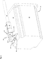
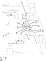
- Figure 1 shows a perspective illustration of a system 10 with a first contact device 20 according to a first embodiment.
- the system 10 has, for example, a component housing 15, the first contact device 20 and a connection line 25.
- an electrical component for example an electric drive motor, can be arranged in the component housing 15.
- the first contact device 20 has a base 30 and a first contact housing 35.
- the base 30 is connected to a side surface 37 of the component housing 15 on a side facing away from the first contact housing 35 on the component housing 15 by means of a fastening means 36, for example screws.
- the connection line 25 is routed parallel to the side surface 37.
- the first contact housing 35 is connected to the base 30 on a side that faces the component housing 15.
- the first contact housing 35 is mounted in the base 30 such that it can rotate about an axis of rotation 40.
- the axis of rotation 40 is oriented perpendicular to the side surface 37.
- the first contact housing 35 On a side facing away from the base 30, the first contact housing 35 has a connection side 45 with which the first contact housing 35 is connected to the connection line 25, in particular to a mating connector 46 arranged on the connection line.
- FIG. 11 shows a detail of a sectional view along a FIG Figure 1 Section plane AA shown through the in Figure 1 System shown 10.
- the first contact housing 35 is designed as an angular housing and is L-shaped in the embodiment.
- the first contact housing 35 has a first housing section 41 and a second housing section 42.
- the first housing section 41 is arranged parallel to the side surface 37 of the component housing 15.
- the second housing section 42 is oriented perpendicular to the first housing section 41 and to the side surface 37 and connected on one side to the first housing section 41.
- the second housing section 42 is connected to the base 30.
- the component housing 15 has a through opening 43.
- the second housing section 42 opens out at the through opening 43 on a side facing away from the first housing section 41.
- the first housing section 41 and essentially the second housing section 42 are designed as a hollow cylinder.
- the first contact housing 35 is preferably formed in one piece and of the same material.
- the first housing section 41 and the second housing section 42 delimit a housing interior 44.
- a plurality of first electrical lines 55 which are each electrically insulated from one another, are arranged in the housing interior 44.
- the first electrical lines 55 are arranged in the housing interior 44 in such a way that the first electrical lines 55 twist by at least 180 ° when the first contact housing 35 is rotated about the axis of rotation 40 and do not block the rotation of the first contact housing 35 or cause damage during the rotation to take.
- the first electrical lines 55 are routed through the through opening 43 into the component housing 15, for example to the component.
- the first contact device 20 has a first contact element 50 on the connection side 45 for each first electrical line 55.
- the first contact element 50 is each connected to an electrical line 55. Furthermore, the first contact element 50 is fastened in the first housing section 41 in the first contact housing 35.
- the connection line 25 has a second contact device 60, for example a mating connector 46, and preferably a plurality of second electrical lines 65.
- the Second contact device 60 has a second contact housing 61 and a second contact element 70 for each second electrical line 65.
- the second contact element 70 is designed to correspond to the first contact element 50 and, in the assembled state of the connection line 25 on the connection side 45 of the first contact device 20, forms an electrical connection with the respectively assigned first contact element 50.
- the second contact element 70 is, for example, designed as a plug contact which engages in the first contact element 50.
- the first contact element 50 can also be designed as a plug contact and the second contact element 70 as a socket contact.
- the second contact element 70 is fastened in the second contact housing 61.
- the second contact housing 61 for example, encompasses the first housing section 41 on the connection side 45 on the circumferential side.
- fastening means and / or latching means can be provided in order to secure the second contact housing 61 against unintentional pulling off from the first contact housing 35.
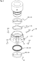
- FIG. 11 shows an exploded view of the FIGS Figures 1 and 2 first contact device 20 shown.
- the first contact device 20 has, in addition to the base 30 and the in Figure 3
- First contact housing 35 shown in abbreviated form has a latching device 90, a clamping device 95 and a sealing device 100.
- the sealing device 100 has a first sealing element 105 second sealing element 110 and a third sealing element 115.
- the first sealing element 105 and the third sealing element 115 are designed, for example, as an O-ring.
- an inner diameter d3 of the third sealing element 115 is greater than an inner diameter d1 of the first sealing element 105.
- the second sealing element 110 preferably has an X-shaped cross section.
- the second sealing element 110 can also be designed differently, for example as an O-ring. Due to the X-shaped configuration of the second sealing element 110, the sealing element 110 seals both in the radial direction and in the axial direction. Furthermore, twisting of the sealing element 100 is avoided. Furthermore, the X-shaped second sealing element 110 has a particularly favorable frictional behavior.
- the tensioning device 95 comprises a corrugated spring 96.
- the corrugated spring 96 is made from a round material and is designed as an open ring.
- Another embodiment of the wave spring 96 would also be conceivable.
- the tensioning device 95 can also have at least one compression spring and / or a plate spring.
- the latching device 90 has at least one latching pin 120.
- four locking pins 120 are provided.
- the number of locking pins 120 can be freely selected. However, it is advantageous if at least three latching pins 120 are provided, which are for example distributed at regular intervals in the circumferential direction relative to the axis of rotation 40.
- FIG. 11 shows a detail of a perspective sectional view along the line in FIG Figure 1 Section plane AA shown through the in Figure 1 base 30 shown.
- the inside of the base 30 is essentially hollow-cylindrical running around the axis of rotation 40 and delimits a base interior 150 on the inside with respect to an environment 151.
- the base 30 has a lower base end face 125 and an upper base end face 130 arranged axially opposite to the axis of rotation 40.
- a circumferential first sealing groove 145 arranged on a first circular path around the axis of rotation 40 is provided on the lower base end face 125.
- the lower base end face 125 of the base 30 rests against the side surface 37 of the component housing 15.
- the first sealing groove 145 is open towards the bottom.
- the first sealing element 105 (in Figure 4 not shown), wherein the first sealing element seals the base interior 150 and the housing interior from the surroundings 151.
- the base 30 has a first base section 141, a second base section 142 and a third base section 143 in the axial direction.
- the first base section 141 adjoins the lower base end face 125.
- the second base section 142 is arranged in the axial direction above directly adjacent to the first base section 141.
- the third base section 143 is arranged adjacent.
- the third base section 143 is arranged in the axial direction between the upper base end face 130 and the second base section 142.
- a first wall thickness w1 is thicker than a second wall thickness w2 of the second base section 142.
- a third wall thickness w3 of the third base section 143 is less than the second wall thickness w2.
- the third base section 143 is made significantly shorter in the axial direction than the first base section 141 and the second base section 142 Direction of the second base section 142 is shorter than the first base section 141.
- an inner base circumferential side 155 has a first shoulder 180.
- the first shoulder 180 has a first support surface 181, which is arranged to run in a plane of rotation relative to the axis of rotation 40.
- the first base section 141 On the inner base circumferential side 155 of the base 30, the first base section 141 has a second sealing groove 160.
- the second sealing groove 160 is open towards the inside towards the base interior 150 and is arranged offset in the axial direction relative to the lower base end face 125.
- the second sealing groove 160 is formed circumferentially around the axis of rotation 40 on a second circular path.
- the second sealing groove 160 like the first sealing groove 145, has a rectangular cross section.
- the first base section 141 has a first recess 175 for each latching pin 120.
- the first recess 175 is designed as a bore and has a recess longitudinal axis 176 which is inclined to the axis of rotation 40, preferably perpendicular to the axis of rotation 40. If several latching pins 120 are provided, the recess longitudinal axes 176 can be arranged in a common plane of rotation with respect to the axis of rotation 40.
- the first recesses 175 can be arranged distributed in the circumferential direction at regular intervals around the circumference.
- the first base section 141 On the inner base circumferential side 155 of the first base section 141, the first base section 141 has a first radial bearing surface 165 of a first radial bearing 170 between the lower base end face 125 and the first recess 175.
- the first radial bearing surface 165 is Here, for example, it is designed to run in a cylindrical manner around the axis of rotation 40.
- a first bevel 185 is provided on the inner base peripheral side 155 of the third base section 143.
- the first bevel 185 has an inclination of approximately 60 ° to 75 ° with respect to the upper base end face 130.
- An outer circumferential side 190 of the base 30 is formed on the first base section 141 to run in a cylindrical manner with respect to the axis of rotation 40.
- the outer base circumferential side 190 is configured in sections in a cylindrical manner on a side facing the first base section 141 and essentially rectangular on a side facing away from the first base section 142.
- the outer base circumferential side 190 is formed on the third base section 143 in the shape of a cylinder around the axis of rotation 40 and is offset radially inward relative to the second base section 142.
- a second shoulder 194 is provided on the outer circumferential side 190 of the base 30 at the transition between the third base section 143 and the second base section 142.
- the second shoulder 194 has a first shoulder surface 195 which runs in a plane of rotation to the axis of rotation 40 and is free on a side facing the upper end face 130 (in the unmounted state of the base 30).
- Figure 5 shows a detail of a side view of the second housing section 42 of the first contact housing 35.
- the second housing section 42 has a second bevel 210 on an outer circumferential housing side 200 adjoining a lower housing end face 205 of the first contact housing 35.
- the second bevel 210 has an inclination of approximately 60 ° to 75 ° with respect to the lower housing end face 205.
- the first radial bearing 170 has a second radial bearing surface 215 axially adjacent to the second bevel 210.
- the second radial bearing surface 215 is designed to correspond to the first radial bearing surface of the base.
- the second radial bearing surface 215 runs in the shape of a cylinder around the axis of rotation 40.
- the latching device 90 On the upper side adjoining the second radial bearing surface 215, the latching device 90 has a latching structure 220 on the outer circumferential side 200 of the housing.
- the latching structure 220 has a disengaging section 225 and a spur toothing 230.
- the spur toothing 230 is arranged in the axial direction between the second radial bearing surface 215 and the unlocking section 225.
- the unlocking section 225 is groove-shaped and is delimited in the axial direction in relation to the axis of rotation 40 on the one hand by the spur toothing 230 and on the other side (on a side facing away from the lower housing face 205) by a groove side surface 235.
- the groove side surface 235 is arranged running in a plane of rotation to the axis of rotation 40.
- a groove base 240 of the unlocking section 225 is designed to run in a cylindrical manner around the axis of rotation 40.
- the unlocking section 225 is open radially outward.
- the spur toothing 230 has at least one first tooth 305 and a second tooth 310 arranged offset in the circumferential direction relative to the first tooth 305.
- the number of teeth 305, 310 of the face gear 230 is in Figure 5 exemplary.
- the spur toothing 230 has a tooth base 315.
- the second housing section 42 has a third shoulder 245, offset in the axial direction relative to the latching structure 220 on a side facing away from the lower housing end face 205 on.
- the third shoulder 245 has a second contact surface 246 which is arranged to run in a plane of rotation relative to the axis of rotation 40.
- the second support surface 246 is in Figure 5 arranged on the side facing the lower housing end face 205.
- a third bevel 250 Adjacent in the axial direction on a side of the second support surface 246 facing away from the lower housing end face 205, a third bevel 250 is additionally provided on the third shoulder 245.
- the third bevel 250 has an inclination of approximately 60 ° to 75 ° with respect to the second support surface 246.
- a second radial bearing 260 has a third radial bearing surface 255.
- the third radial bearing surface 255 is arranged to run in a cylindrical manner around the axis of rotation 40.
- a third sealing groove 265 is provided in the third radial bearing surface 255.
- the third sealing groove 265 is open radially outward.
- a fourth shoulder 270 adjoins the third radial bearing surface 255 on the upper side.
- the outer housing circumferential side 200 of the first contact housing 35 is formed step-like with increasing diameter from the lower housing end face 205 upwards in the direction of the first housing section 41.
- the fourth shoulder 270 has a second shoulder surface 271 on a side facing the lower housing end face 205.
- the second shoulder surface 271 is arranged in a plane of rotation about the axis of rotation 40.
- a second recess 275 is provided in the fourth shoulder 270.
- the second recess 275 is formed in the form of a groove and is formed circumferentially around the axis of rotation 40.
- the second recess 275 is open towards the lower housing end face 205 of the first contact housing 35.
- FIG. 11 shows a detail of a perspective sectional view along the line in FIG Figure 1 Section plane AA shown through the system 10. For reasons of clarity, in Figure 6 only the first contact device 20 is shown.
- the first contact housing 35 is in Figure 6 arranged in a first axial position opposite the base 30.
- the third base section 143 engages the second recess 275 only in sections.
- the second recess 275 and the third base section 143 form a gap seal which, regardless of the axial position of the first contact housing 35 relative to the base 30, prevents dirt particles from penetrating into the base interior 150.
- the second radial bearing 260 has a fourth radial bearing surface 276 on the inner base circumferential side 155 on the second base section 142 axially between the first shoulder 180 and the first bevel 185.
- the fourth radial bearing surface 276 is designed to run cylindrically around the axis of rotation 40 and to correspond to the third radial bearing surface 255.
- the third radial bearing surface 255 rests on the fourth radial bearing surface 276.
- the third sealing element 115 is arranged in the third sealing groove 265.
- the third sealing element 115 rests on the fourth radial bearing surface 276, which in sections also serves as a sealing surface. Due to the high manufacturing quality of the fourth radial bearing surface 276, damage to the third sealing element 115 is avoided in the event of an axial movement of the first contact housing 35 relative to the base 30.
- the first contact device 20 can have a third radial bearing 280.
- the third radial bearing 280 has a fifth radial bearing surface 285 and a sixth radial bearing surface 290.
- the fifth radial bearing surface 285 is arranged on the outer circumferential side 200 of the housing axially between the latching structure 220 and the third shoulder 245.
- the sixth radial bearing surface 290 is arranged on the inner base circumferential side 155.
- the sixth radial bearing surface 290 is arranged in the axial direction between the first shoulder 180 and the recesses 175.
- the sixth radial bearing surface 290 and the fifth radial bearing surface 285 are designed to correspond to one another and run cylindrically around the axis of rotation 40.
- the first radial bearing surface 165 and the sixth radial bearing surface 290 can be designed as a common radial bearing surface.
- the tensioning device 95 is arranged axially between the first shoulder 180 and the third shoulder 245 in a spring chamber 291.
- the ring-shaped spring chamber 291 is delimited radially on the outside by the fourth radial bearing surface 276 and radially on the inside by the fifth radial bearing surface 285.
- the tensioning device 95 is supported on one side on the first support surface 181 and on the other side on the second support surface 246.
- the second sealing element 110 is arranged in the second sealing groove 160. As a result of the arrangement of the second sealing groove 160 on the first radial bearing surface 165, the second sealing element 110 rests on the second radial bearing surface 215, so that damage to the second sealing element 110 can be avoided due to the high surface quality of the first radial bearing 170 designed as a plain bearing.
- the second radial bearing surface 215 rests against the first radial bearing surface 165. Due to the radial bearings 170, 260, 280, which are designed as plain bearings, and the flat contact between the respective associated radial bearing surfaces 165, 215, 255, 276, 285, 290, high forces acting transversely to the axis of rotation 40, which can cause tilting of the second housing section 42 in to the Can cause base interior 150 can be reliably avoided.
- levering or destruction of the first contact housing 35 is reliably avoided via the radial bearings 170, 260, 280 even when high forces act perpendicular to the axis of rotation 40 on the second housing section 42 due to the large axial distance between the radial bearings 170, 260, 280.
- the second housing section 42 Providing the bevels 185, 210, 250 enables the second housing section 42 to be pushed into the base interior 150 particularly easily from above in the direction of the component housing.
- the first bevel 185 prevents squeezing and / or damage to the third sealing element 115
- the second bevel 210 prevents squeezing and / or damage to the second sealing element 110 when the second housing section 42 is pushed axially into the base interior 150. This ensures reliable sealing of the base interior 150 by the second and third sealing elements 110, 115 between the base 30 and the second housing section 42.
- the arrangement of the locking device 90 axially between the second sealing element 110 and the third sealing element 115 reliably prevents contamination or fluids from penetrating into the component housing 15.
- the penetration of possibly broken parts, for example the spur toothing 230, through the second and third sealing elements 110, 115 into the component housing 15 as well as abrasion due to wear of the latching device 90 and thus possible damage to the components arranged in the component housing 15 is also prevented.
- the latching pin 120 has a first pin section 295 and a second pin section 300.
- the first pin portion 295 is connected to the second pin portion 300.
- the Latching pin 120 is cylindrical, the outer diameter extending over the entire length of the latching pin 120.
- the locking pin 120 can be chamfered on the front side.
- the first pin section 295 engages in the first recess 175 of the base 30. It is particularly advantageous here if the first pin section 295 is pressed into the first recess 175. As a result, a reliable hold of the locking pin 120 in the base 30 can be ensured.
- a different type of fastening of the locking pin 120 to the base 30 is also conceivable, so the locking pin 120 can also be connected to the base 30 in a force-locking and / or form-locking and / or material-locking manner.
- the second pin section 300 protrudes into the base interior 150. In the first axial position, as in FIG Figure 6 As shown, the second pin section 300 engages in the spur toothing 230 and secures a position of the first contact housing 35 in the circumferential direction in relation to the axis of rotation 40.
- the system 10 described above is particularly easy and quick to assemble.
- the contact device 20 can also be mounted (partially) automatically.
- the assembly of the system 10 is briefly discussed below, although it is of course possible to deviate from the sequence described below.
- the second sealing element 110 is inserted into the second sealing groove 160.
- the clamping device 95 is introduced into the base interior 150 from above and placed on the first support surface 181.
- the third sealing element 115 is introduced into the third sealing groove 265.
- the first contact housing 35 is then pushed into the base interior 150 until the unlocking section 225 is arranged at the level of the recesses 175.
- the locking pins 120 are then pushed into the recesses 175 and, if necessary, glued.
- the first sealing element 105 is then inserted into the first sealing groove 105 and the first electrical line 55 is threaded through the through opening to the electrical drive motor.
- the base 30 is placed on the side surface 37 and fastened to the component housing 15 by means of the fastening means.
- the electrical line is connected to the first contact element and the first contact element is attached to the connection side of the first contact housing 35.
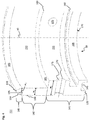
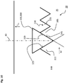
- FIG. 11 shows a detail of a sectional view along a FIG Figure 1 Section plane BB shown through the first contact device 20.
- the first tooth 305 has a first tooth flank 320 on a side facing the second tooth 310 and the second tooth 310 has a second tooth flank 325 on a side facing the first tooth 305.
- the tooth base 315 connects the first tooth flank 320 with the second tooth flank 325.
- the first tooth flank 320 is delimited by a tooth tip 335 and the tooth base 315.
- the tooth head 335 is arranged on a side of the tooth 305, 310 facing the unlocking section 225 and delimits the unlocking section 225 opposite the groove side surface 235.
- Each tooth 305, 310 has a tooth base 340.
- the tooth base 340 is arranged on a side of the tooth 305, 310 facing away from the unlatching section 225.
- the first tooth flank 320 and the second tooth flank 325 are oriented obliquely to the axis of rotation 40, in particular obliquely to a plane in which the axis of rotation 40 runs.
- the first tooth flank 320 and the second tooth flank 325 can also be aligned parallel to one another, each of the tooth flanks 320, 325 being arranged in a common plane with the axis of rotation 40.
- first tooth flank 320, the tooth base 315 and the second tooth flank 325 are arranged on a common arc, in particular on a common circular path with a center point 330.
- the center point 330 can be arranged in the unlatching section 225.
- the center point 330 can also be arranged outside the unlocking section 225, for example on a side of the unlocking section 225 facing away from the spur toothing 230 in the axial direction.
- the first tooth flank 320 forms an angle ⁇ with the second tooth flank 325 at the tooth tip 335. It is particularly advantageous if the angle ⁇ is an acute or an obtuse angle. It is also advantageous if the angle ⁇ is in a range from 0 ° to 170 °, in particular in a range from 30 ° to 90 °. The angle is advantageously 60 °.
- the second pin section 300 has a contact surface 345 on a side facing the face toothing 230.
- the contact surface 345 is, for example, cylindrical and is designed to correspond to the first tooth flank 320, the tooth base 315 and the second tooth flank 325.
- the unlocking section 225 has an axial width in the axial direction between the tooth tip 335 and the groove side surface 235 which corresponds approximately to an axial extension of the second pin section 300, in the embodiment a diameter of the second pin section 300.
- the contact surface 345 is in the first axial position, as shown in FIG Figure 7 is shown, on the first tooth flank 320, the second tooth flank 325 and the tooth base 315, so that a position in the circumferential direction of the first contact housing 35 is set relative to base 30. Furthermore, because the contact surface 345 rests on the tooth base 315, undesired axial movement of the first contact housing 35 with respect to the axis of rotation 40 relative to the base 30 is avoided. Alternatively, it is also conceivable that the contact surface 345 also only rests exclusively on one of the tooth flanks 320, 325 or exclusively only on the tooth base 315 and is arranged at a distance from the tooth flanks 320, 325.
- the tensioning device 95 is relaxed in the first axial position.
- the tensioning device 95 can be pretensioned in the first axial position.
- the preload has the advantage that if, for example, the contact surface 345 only rests against the tooth base 315, the preload between the contact surface 345 and the tooth base 315 creates a frictional connection and so in the circumferential direction the first contact housing 35 only after overcoming the frictional connection around the axis of rotation 40 can be twisted.
- the tensioning device 95 provides a first axial force F A1 in the first axial position.
- the first axial force F A1 is introduced into the first contact housing 35 through the third shoulder 245.
- the first axial force F A1 acts, for example, in an upward direction.
- the spur toothing 230 is pulled upwards and pressed against the contact surface 345 with the first axial force F A1.
- This configuration has the advantage that the first contact housing 35 is arranged without play relative to the base 30 in the axial direction.
- FIG. 13 shows a sectional view along the line in FIG Figure 1 Section plane AA shown through the in Figure 1 shown first contact device 20, wherein the first contact housing 35 is arranged in a second axial position.
- the first contact housing 35 is shifted downward in the direction of the component housing 15.
- the locking pin 120 does not engage in the face toothing 230, but rather engages in the unlocking section 225.
- the unlocking section 225 is designed as a ring-shaped circumferential groove, so that a movement of the first contact housing 35 relative to the base 30 around the axis of rotation 40 and the second axial position is released in the circumferential direction and, as a result, for example, the first housing section can be aligned in such a way that the connection line, but at least the second contact device and the first housing section are aligned with one another.
- the second housing section 42 protrudes into the through opening 43.
- the unlatching of the latching device 90 for transferring the first contact housing 35 from the first axial position into the second axial position can take place in two possible variants.
- the first contact housing 35 by a user of the system on the upper side to the first terminal housings 35 are pushed with a second axial force F A2, wherein by means of the second axial force F A2, the first contact housing 35 relative to the base 30 first from the relatively against the action of the clamping device 95 Axial position (cf. Figure 7 ) into the second axial position (cf. Figure 8 ) is transferred until the locking pin 120 only engages in the unlatching section 225 and is thus arranged outside of the spur toothing 230. If the second axial force F A2 is maintained, the first contact housing 35 can be rotated relative to the base 30 about the axis of rotation 40.
- the axial displacement of the first contact housing 35 with respect to the base 30 is limited in the embodiment by the fact that the second pin section 300 strikes the groove side surface 235 on a side facing away from the spur toothing 230. This prevents the tensioning device 90 from being overpressed.
- the second shoulder surface 271 can also strike the first shoulder surface 195 and thus limit the movement of the first contact housing 35 in the direction of the base 30 or the component housing 15.
- the tensioning device 95 is tensioned in the second axial position and provides a third axial force F A3 which acts against the second axial force F A2. If the second axial force F A2 is canceled after the first contact housing 35 has been rotated, the third axial force F A3 promotes the first contact housing 35 from the second axial position back into the first axial position.
- the second pin section snaps into place between two teeth.
- a torque M about the axis of rotation 40 is introduced into the first contact device 20 by the user in order to rotate the first contact housing 35 with respect to the base 30. Due to the inclined alignment of the first tooth flank 320 and the contact surface 345 corresponding to the first tooth flank 320, the torque M effects a conversion of part of the torque M into the second axial force F A2 .
- the second axial force F A2 acts against the third axial force F A3 , and if the second axial force F A2 is greater than the third axial force F A3 , the first tooth flank slides on the contact surface 345 of the locking pin 120 while the first contact housing 35 is rotated .
- the spur toothing 230 or the first contact housing 35 is moved from the first axial position into the second axial position by the second axial force F A2 in the direction of the component housing 15 postponed. If the second pin section 300 slides over the tooth head, the first contact housing 35 is in the second axial position.
- the tensioning device returning the first contact housing 35 to the first axial position with the second axial force F A2 until the second pin section 300 is arranged centrally between the teeth. If the torque M is further maintained, the described snapping axial movement is repeated between the first axial position and the second axial position until the first contact section branches off in the desired direction. The first lines are twisted within the first contact housing 35.
- the first contact device 20 can have an anti-rotation device which is designed to allow only a rotation of the first contact housing 35 by a predefined further angle, for example 350 °, in order to allow the axis of rotation 40 with respect to the base 30. This ensures that the first electrical line is not twisted too much in the first contact device 20.
- the second variant has the advantage that the user is additionally provided with a haptic feeling when rotating the first contact device 20, by means of which the user is informed that the locking pin 120 has engaged after the torque M has been provided between the teeth. Furthermore, the first contact housing 35 can be rotated about the axis of rotation 40 even if the installation space is restricted.
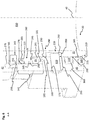
- FIG. 13 shows a sectional view along a line in FIG Figure 1 Section plane CC shown through the in Figure 1 first contact device 20 shown.
- the spur toothing 230 has a tooth pitch which is selected such that in the first axial position all of the latching pins 120 engage in the spur toothing 230. Furthermore, even when the torque M is introduced about the axis of rotation 40 into the first contact housing 35, only one tooth flank 320, 325 of the spur toothing 230 is constantly loaded and the other tooth flanks 320, 325 of the spur toothing 230 are unloaded. This avoids uneven wear of the spur toothing 230 and of the latching pin 120.
- the distance between two locking pins 120 which is selected uniformly in the circumferential direction, in the embodiment the locking pins 120 are each arranged at a 90 ° angle to one another, furthermore ensures that when the first contact housing 35 is transferred from the first axial position to the second axial position and from the second axial position back into the first axial position, the first contact housing 35 is not tilted in the base interior 150 and / or at least one of the radial bearings is overstressed.
- a fastening opening 350 can be provided laterally on the outer base circumferential side 190 in a corner area of the first base section 141 in order to releasably fasten the base 30 to the component housing by means of the fastening means, for example a screw connection, and to press the first sealing element against the side surface.
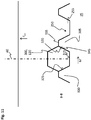
- FIG. 11 shows a detail of a sectional view along the line in FIG Figure 1 according to a first embodiment shown section plane BB through a first contact device 20 according to a second embodiment.
- the first contact device 20 is essentially identical to that in FIG Figures 1 to 9 first contact device shown.
- the first tooth flank 320 axially abuts the second tooth flank 325 directly on a side of the teeth 305, 310 facing away from the unlatching section 225.
- the tooth 305, 310 has an exemplary triangular cross section.
- the tooth flank 320, 325 and the respectively corresponding contact surface 345 are each arranged in a plane which is inclined to the plane in which the axis of rotation 40 runs.
- the tooth flank 320, 325 and the contact surface 345 are each designed to correspond to one another and are designed to be planar in the embodiment.
- the latching pin 120 has a triangular, preferably an isosceles triangular, cross section at least in the second pin section 300.
- FIG. 13 shows a sectional view along the line in FIG Figure 1 Section plane BB shown through a first contact device 20 according to a third embodiment.
- the first contact device 20 is essentially a combination of that in FIG Figure 10 and the one in the Figures 1 to 9 shown first contact device.
- the latching pin 120 is polygonal at least in the second pin section 300.
- the polygonal cross section can also extend over the entire extent of the locking pin 120.
- the recess into which the first pin section engages would also have a polygonal design corresponding to the polygonal configuration of the latching pin 120.
- the spur toothing 230 is designed in such a way that the Tooth head 335 is planar to delimit the unlocking section 225 and runs in a plane of rotation to the axis of rotation 40.
- the tooth flanks 320, 325 and the contact surface 345 provided to correspond to the tooth flank 320, 325 are designed to be planar.
- the tooth flank 320, 325 could also be convex or concave and the respective corresponding contact surface 345 could be concave or convex.
- the tooth base 315 is provided.
- the second pin section 300 also rests against the tooth base 315 with the contact surface 345 and against the tooth flanks 320, 325. It would also be conceivable that the tooth base 315 is arranged at a distance from the contact surface 345.
Landscapes
- Details Of Connecting Devices For Male And Female Coupling (AREA)
- Regulating Braking Force (AREA)
- Rotary Pumps (AREA)
- Sealing Devices (AREA)
Description
Die Erfindung betrifft eine Kontakteinrichtung gemäß Anspruch 1, die ein Kontaktgehäuse, einen Sockel und eine Rasteinrichtung aufweist. Das Kontaktgehäuse greift in einen Sockelinnenraum des Sockels ein und ist drehbar gegenüber dem Sockel verdrehbar. Die Rasteinrichtung verhindert ein ungewolltes Verdrehen des Kontaktgehäuses gegenüber dem Sockel.The invention relates to a contact device according to claim 1, which has a contact housing, a base and a latching device. The contact housing engages in a socket interior of the socket and is rotatable relative to the socket. The latching device prevents unwanted rotation of the contact housing with respect to the base.
Diese Anmeldung beansprucht die Priorität der deutschen Patentanmeldung
Aus
Aus
Aus
Aus der
Werden lange Kabel an dem Steckergehäuse angeschlossen, können die Kabel sich aufschwingen und/oder Vibrationen in das Steckergehäuse einleiten. Die dabei auftretenden Kräfte können unter ungünstigen Umständen zu einem Aufhebeln des Steuergehäuses aus der Flanschhülse und somit zu einer irreparablen Beschädigung der Kontakteinrichtung führen.If long cables are connected to the connector housing, the cables can swing open and / or introduce vibrations into the connector housing. Under unfavorable circumstances, the forces that occur can lead to the control housing being levered out of the flange sleeve and thus irreparable damage to the contact device.
Es ist Aufgabe der Erfindung, eine besonders ergonomische und gleichzeitig besonders stabile verdrehbare Kontakteinrichtung bereitzustellen.It is the object of the invention to provide a particularly ergonomic and at the same time particularly stable rotatable contact device.
Diese Aufgabe wird mittels einer Kontakteinrichtung gemäß Patentanspruch 1 gelöst. Vorteilhafte Ausführungsformen sind in den abhängigen Ansprüchen angegeben.This object is achieved by means of a contact device according to patent claim 1. Advantageous embodiments are specified in the dependent claims.
Es wurde erkannt, dass eine verbesserte Kontakteinrichtung dadurch bereitgestellt werden kann, dass die Kontakteinrichtung ein Kontaktgehäuse, einen Sockel, eine Spanneinrichtung und eine Rasteinrichtung aufweist. Der Sockel begrenzt einen Sockelinnenraum, wobei das Kontaktgehäuse zumindest abschnittweise in den Sockelinnenraum eingreift, wobei die Rasteinrichtung an einer äußeren Gehäuseumfangsseite des Kontaktgehäuses eine Raststruktur und wenigstens einen Verraststift aufweist, wobei die Raststruktur eine Stirnverzahnung und einen in axialer Richtung an die Stirnverzahnung angrenzenden Entrastungsabschnitt aufweist, wobei der Entrastungsabschnitt nutförmig in Umfangsrichtung zumindest abschnittsweise umlaufend um das Kontaktgehäuse ausgebildet ist, wobei der Verraststift mit dem Sockel verbunden ist und in den Sockelinnenraum hineinragt, wobei das Kontaktgehäuse relativ zum Sockel zwischen einer ersten Axialposition und einer zweiten Axialposition in axialer Richtung verschiebbar ist, wobei in der ersten Axialposition der Verraststift in die Stirnverzahnung eingreift und in Umfangsrichtung eine Position des Kontaktgehäuses gegenüber dem Sockel sichert, wobei in der zweiten Axialposition der Verraststift in den Entrastungsabschnitt eingreift und das Kontaktgehäuse in Umfangsrichtung verdrehbar um eine Drehachse gegenüber dem Sockel ist. Die Spanneinrichtung ist zwischen dem Sockel und dem Kontaktgehäuse in dem Sockelinnenraum angeordnet, wobei das Kontaktgehäuse aus der ersten Axialposition gegen die Wirkung der Spanneinrichtung in die zweite Axialposition verschiebbar ist, wobei in der zweiten Axialposition die Spanneinrichtung eine Axialkraft zur Überführung des Kontaktgehäuses zurück in die erste Axialposition bereitstellt.It has been recognized that an improved contact device can be provided in that the contact device has a contact housing, a base, a clamping device and a latching device. The base delimits a base interior, the contact housing engaging at least in sections into the base interior, the latching device having a latching structure and at least one latching pin on an outer circumferential side of the contact housing, the latching structure having a spur toothing and an unlocking section adjoining the spur toothing in the axial direction, wherein the unlocking section is groove-shaped in the circumferential direction, at least in sections is formed circumferentially around the contact housing, the locking pin being connected to the base and protruding into the base interior, the contact housing being displaceable in the axial direction relative to the base between a first axial position and a second axial position, the locking pin being in the first axial position Front teeth engage and secure a position of the contact housing relative to the base in the circumferential direction, wherein in the second axial position the locking pin engages in the unlocking section and the contact housing is rotatable in the circumferential direction about an axis of rotation relative to the base. The clamping device is arranged between the base and the contact housing in the base interior, the contact housing being displaceable from the first axial position against the action of the clamping device into the second axial position, wherein in the second axial position the clamping device exerts an axial force to transfer the contact housing back into the first Provides axial position.
Diese Ausgestaltung hat den Vorteil, dass die Kontakteinrichtung besonders stabil ist. Insbesondere wird vermieden, dass das Kontaktgehäuse durch eine Querkraft quer zur Drehachse aus dem Sockel ausgehebelt werden kann. Ferner ist die Verrastung des Kontaktgehäuses im Sockel besonders einfach und kostengünstig ausgebildet.This configuration has the advantage that the contact device is particularly stable. In particular, it is avoided that the contact housing can be levered out of the base by a transverse force transverse to the axis of rotation. Furthermore, the latching of the contact housing in the base is particularly simple and inexpensive.
In einer weiteren Ausführungsform weist die Stirnverzahnung wenigstens einen ersten Zahn und einen zweiten Zahn auf, wobei in Umfangsrichtung der erste Zahn beabstandet zu dem zweiten Zahn angeordnet ist, wobei zwischen den Zähnen die Stirnverzahnung einen Zahngrund aufweist, wobei der Verraststift einen Stiftabschnitt aufweist, wobei der Stiftabschnitt in dem Sockelinnenraum angeordnet ist und umfangsseitig auf einer der Stirnverzahnung zugewandten Seite eine Anlagefläche aufweist, wobei in der ersten Axialposition die Anlagefläche zumindest abschnittweise am Zahngrund anliegt, oder wobei in der ersten Axialposition die Anlagefläche beabstandet zum Zahngrund angeordnet ist. Dadurch kann in der ersten Axialposition eine zuverlässige Verrastung sichergestellt werden.In a further embodiment, the spur gearing has at least a first tooth and a second tooth, the first tooth being arranged at a distance from the second tooth in the circumferential direction, the spur gearing having a tooth base between the teeth, the locking pin having a pin section, the The pin section is arranged in the base interior and has a contact surface on the circumferential side on a side facing the face toothing, the contact surface at least in sections on the tooth base in the first axial position is applied, or wherein in the first axial position the contact surface is arranged at a distance from the tooth base. Reliable latching can thereby be ensured in the first axial position.
In einer weiteren Ausführungsform weist die Stirnverzahnung wenigstens einen ersten Zahn mit einer ersten Zahnflanke auf, wobei der Verraststift einen Stiftabschnitt aufweist, wobei der Stiftabschnitt in dem Sockelinnenraum angeordnet ist und umfangsseitig auf der Stirnverzahnung zugewandten Seite eine Anlagefläche aufweist, wobei die erste Zahnflanke zumindest abschnittsweise schräg geneigt zu einer Ebene in der Drehachse verläuft, ausgerichtet ist, oder wobei die erste Zahnflanke und die Drehachse parallel zueinander verlaufend ausgerichtet sind, wobei in der ersten Axialposition die Anlagefläche an der ersten Zahnflanke anliegt.In a further embodiment, the spur toothing has at least one first tooth with a first tooth flank, the latching pin having a pin section, the pin section being arranged in the base interior and having a contact surface on the circumferential side on the side facing the front toothing, the first tooth flank being at least partially inclined runs inclined to a plane in the axis of rotation, is oriented, or wherein the first tooth flank and the axis of rotation are oriented parallel to one another, wherein in the first axial position the contact surface rests on the first tooth flank.
In einer weiteren Ausführungsform weist die Stirnverzahnung wenigstens einen ersten Zahn mit einer ersten Zahnflanke auf, wobei der Verraststift einen Stiftabschnitt aufweist, wobei der Stiftabschnitt in dem Sockelinnenraum angeordnet ist und umfangsseitig auf einer der ersten Zahnflanke zugewandten Seite eine Anlagefläche aufweist, wobei die erste Zahnflanke zumindest abschnittsweise schräg geneigt zu einer Ebene in der Drehachse verläuft, ausgerichtet ist, oder wobei die erste Zahnflanke und die Drehachse parallel zueinander verlaufend ausgerichtet sind, wobei in der ersten Axialposition die Anlagefläche an der ersten Zahnflanke anliegt.In a further embodiment, the spur toothing has at least one first tooth with a first tooth flank, the latching pin having a pin section, the pin section being arranged in the base interior and circumferentially having a contact surface on a side facing the first tooth flank, the first tooth flank at least runs inclined in sections to a plane in the axis of rotation, is aligned, or wherein the first tooth flank and the axis of rotation are aligned parallel to each other, wherein in the first axial position the contact surface rests on the first tooth flank.
In einer weiteren Ausführungsform ist die erste Zahnflanke derart ausgerichtet, dass in Zusammenwirkung mit der Anlagefläche bei Verdrehung des Kontaktgehäuses relativ zum Sockel um die Drehachse durch eine Gleitbewegung der ersten Zahnflanke an der Anlagefläche eine axiale Verschiebung des Kontaktgehäuses von der ersten Axialposition in die zweite Axialposition bewirkt wird. Dadurch muss vom Nutzer keine zusätzliche Axialkraft in das Kontaktgehäuse eingeleitet werden, um das Kontaktgehäuse relativ zum Sockel zu verschieben und die Drehbewegung des Kontaktgehäuses um die Drehachse relativ zum Sockel durchzuführen. Dies ist besonders ergonomisch bei engen Bauraumverhältnissen. Ferner kann die Verdrehung zur Ausrichtung des ersten Kontaktgehäuses relativ zum Sockel besonders schnell durchgeführt werden.In a further embodiment, the first tooth flank is aligned in such a way that, in cooperation with the contact surface, when the contact housing is rotated relative to the base about the axis of rotation, sliding movement of the first tooth flank on the contact surface causes an axial displacement of the contact housing from the first axial position into the second axial position will. This means that the user does not have to additional axial force can be introduced into the contact housing in order to move the contact housing relative to the base and to carry out the rotational movement of the contact housing about the axis of rotation relative to the base. This is particularly ergonomic in tight spaces. Furthermore, the rotation for aligning the first contact housing relative to the base can be carried out particularly quickly.
In einer weiteren Ausführungsform weist der erste Zahn einen Zahnkopf und einen Zahnfuß auf. In axialer Richtung wird an einer ersten axialen Seite der Entrastungsabschnitt durch den Zahnkopf begrenzt und der Zahnfuß ist auf einer dem Entrastungsabschnitt abgewandten Seite des ersten Zahns angeordnet. An einer zur ersten axialen Seite in axialer Richtung gegenüberliegenden zweiten axialen Seite wird der Entrastungsabschnitt durch eine Nutseitenfläche begrenzt. Vorzugsweise ist die Nutseitenfläche in einer Drehebene zur Drehachse angeordnet. Dadurch kann die Verraststruktur besonders kompakt und einfach an dem Kontaktgehäuse ausgebildet werden. Insbesondere kann dadurch das Kontaktgehäuse beispielsweise mittels eines Sinterverfahrens oder eines Spritzgussverfahrens besonders einfach und kostengünstig hergestellt werden.In a further embodiment, the first tooth has a tooth head and a tooth foot. In the axial direction, the unlatching section is delimited on a first axial side by the tooth head and the tooth base is arranged on a side of the first tooth facing away from the unlatching section. On a second axial side opposite the first axial side in the axial direction, the unlocking section is delimited by a groove side surface. The groove side surface is preferably arranged in a plane of rotation to the axis of rotation. As a result, the latching structure can be designed to be particularly compact and simple on the contact housing. In particular, the contact housing can thereby be produced particularly simply and inexpensively, for example by means of a sintering process or an injection molding process.
In einer weiteren Ausführungsform ist die Anlagefläche des Stiftabschnitts im Querschnitt zumindest abschnittweise bogenförmig und/oder plan und/oder polygonförmig und/oder konkav und/oder konvex ausgebildet.In a further embodiment, the contact surface of the pin section is at least partially curved and / or planar and / or polygonal and / or concave and / or convex in cross section.
In einer weiteren Ausführungsform weist der zweite Zahn auf einer dem ersten Zahn zugewandten Seite eine zweite Zahnflanke auf, wobei in der ersten Axialposition die Anlagefläche an der ersten Zahnflanke und an der zweiten Zahnflanke.In a further embodiment, the second tooth has a second tooth flank on a side facing the first tooth, the contact surface on the first tooth flank and on the second tooth flank in the first axial position.
In einer weiteren Ausführungsform sind die erste Zahnflanke, der Zahngrund und die zweite Zahnflanke auf einem gemeinsamen Bogen, insbesondere auf einer gemeinsamen Kreisbahn, mit einem Mittelpunkt angeordnet, wobei der Mittelpunkt im Entrastungsabschnitt angeordnet ist, oder wobei der Mittelpunkt außerhalb des Entrastungsabschnitts vorzugsweise auf einer der Stirnverzahnung abgewandten Seite des Entrastungsabschnitts angeordnet ist. Dadurch können ein besonders einfacher Verraststift und eine besonders einfach ausgebildete Stirnverzahnung bereitgestellt werden, die besonders einfach und kostengünstig herstellbar sind.In a further embodiment, the first tooth flank, the tooth base and the second tooth flank are arranged on a common arc, in particular on a common circular path, with a center point, the center point being located in the unlocking section, or the center point outside the unlocking section, preferably on one of the Facing teeth facing away from the side of the Entrastungsabschnitts is arranged. As a result, a particularly simple latching pin and a particularly simple face toothing can be provided, which can be produced particularly easily and inexpensively.
In einer weiteren Ausführungsform schließt wobei die erste Zahnflanke zu der zweiten Zahnflanke einen Winkel einschließt, wobei der Winkel ein stumpfer oder ein spitzer Winkel ist, wobei der Winkel insbesondere in einem Bereich von 0° bis 170°, insbesondere in einem Bereich von 30° bis 90°, liegt, wobei insbesondere der Winkel 60° beträgt, oder wobei die erste Zahnflanke und die zweite Zahnflanke parallel zueinander ausgerichtet sind.In a further embodiment, the first tooth flank encloses an angle with the second tooth flank, the angle being an obtuse or an acute angle, the angle in particular in a range from 0 ° to 170 °, in particular in a range from 30 ° to 90 °, wherein in particular the angle is 60 °, or wherein the first tooth flank and the second tooth flank are aligned parallel to one another.
In einer weiteren Ausführungsform ist in der ersten Axialposition die Spanneinrichtung entspannt. Alternativ ist in der ersten Axialposition die Spanneinrichtung vorgespannt und presst mit einer weiteren Axialkraft die Stirnverzahnung gegen die Anlagefläche. Dadurch werden auch in der ersten Axialposition ein Anliegen der Stirnverzahnung an der Anlagefläche sichergestellt und ein Klappern der Kontakteinrichtung aufgrund von Vibrationen zuverlässig vermieden.In a further embodiment, the tensioning device is relaxed in the first axial position. Alternatively, the tensioning device is pretensioned in the first axial position and presses the face toothing against the contact surface with a further axial force. This ensures that the face toothing rests against the contact surface even in the first axial position and reliably prevents the contact device from rattling due to vibrations.
In einer weiteren Ausführungsform weist die Spanneinrichtung vorzugsweise wenigstens eine Tellerfeder und/oder eine Wellfeder und/oder eine Druckfeder auf. Der Sockel weist auf einer dem Sockelinnenraum zugewandten Seite einen ersten Absatz und das Kontaktgehäuse einen radial außenseitig angeordneten zweiten Absatz auf. Die Spanneinrichtung ist axial zwischen dem ersten Absatz und dem zweiten Absatz angeordnet, wobei sich die Spanneinrichtung an einer Seite an dem ersten Absatz und an der anderen Seite an dem zweiten Absatz abstützt. Dadurch kann eine besonders in radialer Richtung kompakte Kontakteinrichtung bereitgestellt werden, durch die eine große Anzahl von elektrischen Leitungen geführt werden kann.In a further embodiment, the tensioning device preferably has at least one plate spring and / or a wave spring and / or a compression spring. The base has a first shoulder on a side facing the base interior and the contact housing has a second shoulder arranged radially on the outside. The clamping device is axially arranged between the first shoulder and the second shoulder, the tensioning device being supported on one side on the first shoulder and on the other side on the second shoulder. This makes it possible to provide a contact device which is compact, particularly in the radial direction, through which a large number of electrical lines can be routed.
In einer weiteren Ausführungsform weist der Sockel wenigstens eine Aussparung auf, wobei die Aussparung geneigt zu der Drehachse, vorzugsweise in einer weiteren Drehebene zu der Drehachse angeordnet ist. Der Verraststift weist einen weiteren Stiftabschnitt auf. Der weitere Stiftabschnitt greift zumindest abschnittweise in die Aussparung ein, wobei der weitere Stiftabschnitt vorzugsweise kraftschlüssig und/oder formschlüssig und/oder stoffschlüssig mit dem Sockel verbunden ist. Vorzugsweise ist der weitere Stiftabschnitt in der Aussparung verpresst.In a further embodiment, the base has at least one recess, the recess being arranged at an angle to the axis of rotation, preferably in a further plane of rotation to the axis of rotation. The locking pin has a further pin section. The further pin section engages at least in sections in the recess, the further pin section preferably being connected to the base in a non-positive and / or form-fitting and / or cohesive manner. The further pin section is preferably pressed into the recess.
In einer weiteren Ausführungsform weist die Kontakteinrichtung ein erstes Radiallager auf. Das erste Radiallager weist an einer inneren Sockelumfangsseite des Sockels axial zwischen einer unteren Sockelstirnseite und dem Verraststift eine erste Radiallagerfläche auf. Das erste Radiallager weist an der äußeren Gehäuseumfangsseite des Kontaktgehäuses axial zwischen einer unteren Stirnseite des Kontaktgehäuses und der Verraststruktur eine zur ersten Radiallagerfläche korrespondierend ausgebildete zweite Radiallagerfläche auf, wobei die erste Radiallagerfläche und die zweite Radiallagerfläche vorzugsweise zylindrisch um die Drehachse verlaufend ausgebildet sind, wobei sich die zweite Radiallagerfläche an der ersten Radiallagerfläche abstützt. Dadurch kann ein Verkippen des Kontaktgehäuses in dem Sockel bei Einleitung einer Kraft senkrecht zur Drehachse zuverlässig vermieden werden bzw. die eingeleitete Kraft zuverlässig aus dem Kontaktgehäuse am Sockel abgestützt werden.In a further embodiment, the contact device has a first radial bearing. The first radial bearing has a first radial bearing surface on an inner circumferential side of the base axially between a lower base end face and the locking pin. The first radial bearing has on the outer circumferential side of the contact housing axially between a lower end face of the contact housing and the latching structure a second radial bearing surface designed to correspond to the first radial bearing surface, the first radial bearing surface and the second radial bearing surface preferably being designed to run cylindrically around the axis of rotation, the second radial bearing surface is supported on the first radial bearing surface. As a result, tilting of the contact housing in the base when a force is introduced perpendicular to the axis of rotation can be reliably avoided or the force introduced can be reliably supported from the contact housing on the base.
In einer weiteren Ausführungsform weist die Kontakteinrichtung ein zweites Radiallager auf, wobei das zweite Radiallager axial gegenüberliegend zu dem ersten Radiallager angeordnet ist, wobei das zweite Radiallager an der äußeren Gehäuseumfangsseite des Kontaktgehäuses eine dritte Radiallagerfläche aufweist, wobei das zweite Radiallager an der inneren Sockelumfangsseite des Sockels eine axial zwischen einer der unteren Sockelstirnseite gegenüberliegenden oberen Sockelstirnseite und dem Verraststift angeordnete vierte Radiallagerfläche aufweist, wobei die dritte Radiallagerfläche und die vierte Radiallagerfläche, vorzugsweise zylindrisch, um die Drehachse verlaufend ausgebildet sind, wobei sich die dritte Radiallagerfläche an der vierten Radiallagerfläche abstützt, wobei vorzugsweise das erste Radiallager in radialer Richtung schmäler ausgebildet ist als das zweite Radiallager. Diese Ausgestaltung hat den Vorteil, dass die Kontakteinrichtung besonders in radialer Richtung kompakt gehalten werden kann. Ferner wird ein besonders großer axialer Abstand zwischen dem ersten Radiallager und dem zweiten Radiallager bereitgestellt, sodass ein Herauskippen aus dem Sockel bei Einleitung der Kraft quer senkrecht zur Drehachse des Kontaktgehäuses zuverlässig vermieden werden kann bzw. die Kraft senkrecht zur Drehachse zuverlässig über die Radiallager aus dem Kontaktgehäuse an dem Sockel abgestützt werden kann.In a further embodiment, the contact device has a second radial bearing, the second radial bearing being arranged axially opposite the first radial bearing, the second radial bearing having a third radial bearing surface on the outer circumferential side of the contact housing, the second radial bearing on the inner circumferential side of the base has a fourth radial bearing surface arranged axially between an upper base end face opposite the lower base end face and the latching pin, the third radial bearing surface and the fourth radial bearing surface being designed, preferably cylindrical, to run around the axis of rotation, the third radial bearing surface being supported on the fourth radial bearing surface, preferably the first radial bearing is designed to be narrower in the radial direction than the second radial bearing. This configuration has the advantage that the contact device can be kept compact, particularly in the radial direction. Furthermore, a particularly large axial distance is provided between the first radial bearing and the second radial bearing, so that tilting out of the base when the force is introduced transversely perpendicular to the axis of rotation of the contact housing can be reliably avoided or the force perpendicular to the axis of rotation can be reliably avoided via the radial bearing from the Contact housing can be supported on the base.
In einer weiteren Ausführungsform weist die Kontakteinrichtung eine Dichteinrichtung mit wenigstens einem Dichtelement auf. Das Dichtelement ist axial zwischen dem Verraststift und der unteren Sockelstirnseite angeordnet. Das Dichtelement ist in radialer Richtung zwischen dem Sockel und dem Kontaktgehäuse angeordnet. Das Dichtelement dichtet den Sockelinnenraum fluidisch gegenüber einer Umgebung ab. Vorzugsweise weist das Dichtelement einen X-förmigen Querschnitt auf. Dadurch wird das Eindringen von Verschmutzungen und/oder Flüssigkeiten in den Sockelinnenraum zuverlässig vermieden. Ferner wird durch die Abdichtung auch eine zuverlässige Verschiebbarkeit zwischen der ersten axialen Position und der zweiten axialen Position des Kontaktgehäuses gegenüber dem Sockel sichergestellt. Durch die X-förmige Ausgestaltung des Dichtelements dichtet das Dichtelement sowohl in radialer Richtung als auch in axialer Richtung. Ferner wird ein Verdrillen des Dichtelements bei der Verschiebung des Kontaktgehäuses zwischen den Axialpositionen vermieden. Ferner weist das X-förmige Dichtelement ein besonders niedriges Reibungsverhalten auf.In a further embodiment, the contact device has a sealing device with at least one sealing element. The sealing element is arranged axially between the locking pin and the lower base face. The sealing element is arranged in the radial direction between the base and the contact housing. The sealing element fluidically seals the base interior from an environment. The sealing element preferably has an X-shaped cross section. This will prevent the ingress of Dirt and / or liquids in the base interior reliably avoided. Furthermore, the seal also ensures reliable displaceability between the first axial position and the second axial position of the contact housing with respect to the base. Due to the X-shaped configuration of the sealing element, the sealing element seals both in the radial direction and in the axial direction. Furthermore, twisting of the sealing element when the contact housing is shifted between the axial positions is avoided. Furthermore, the X-shaped sealing element has a particularly low friction behavior.
In einer weiteren Ausführungsform weist das Kontaktgehäuse einen ersten Gehäuseabschnitt und einen mit dem ersten Gehäuseabschnitt verbundenen zweiten Gehäuseabschnitt auf. Der zweite Gehäuseabschnitt ist zumindest teilweise in dem Sockelinnenraum und der erste Gehäuseabschnitt außerhalb des Sockelinnenraums angeordnet. Der erste Gehäuseabschnitt ist geneigt, vorzugweise senkrecht, zu dem zweiten Gehäuseabschnitt angeordnet. Der erste Gehäuseabschnitt und der zweite Gehäuseabschnitt sind formschlüssig und/oder kraftschlüssig und/oder stoffschlüssig miteinander verbunden oder sind einstückig und materialeinheitlich ausgebildet.In a further embodiment, the contact housing has a first housing section and a second housing section connected to the first housing section. The second housing section is at least partially arranged in the interior of the base and the first housing section is arranged outside of the interior of the base. The first housing section is inclined, preferably perpendicular, to the second housing section. The first housing section and the second housing section are positively and / or non-positively and / or cohesively connected to one another or are formed in one piece and made of the same material.
Nachfolgend wird die Erfindung anhand von Figuren näher erläutert. Dabei zeigen:
-
Figur 1 eine perspektivische Darstellung eines Systems; -
Figur 2 einen Ausschnitt einer Schnittansicht entlang einer inFigur 1 gezeigten Schnittebene A-A durch das inFigur 1 gezeigte System; -
Figur 3 eine Explosionsdarstellung der in denFiguren 1 und2 gezeigten ersten Kontakteinrichtung; -
Figur 4 einen Ausschnitt einer Schnittansicht entlang der inFigur 1 gezeigten Schnittebene A-A durch den in denFiguren 1 bis 3 gezeigten Sockel; -
Figur 5 einen Ausschnitt einer Seitenansicht auf den zweiten Gehäuseabschnitt des ersten Kontaktgehäuses; -
Figur 6 einen Ausschnitt der inFigur 2 gezeigten Schnittansicht entlang der inFigur 1 gezeigten Schnittebene A-A durch das System; -
Figur 7 einen Ausschnitt einer Schnittansicht entlang einer inFigur 1 gezeigten Schnittebene B-B durch die erste Kontakteinrichtung; -
Figur 8 eine Schnittansicht entlang der inFigur 1 gezeigten Schnittebene A-A durch die inFigur 1 gezeigte erste Kontakteinrichtung, wobei sich das erste Kontaktgehäuse gegenüber dem Sockel in einer zweiten Axialposition befindet; -
Figur 9 eine Schnittansicht entlang einer inFigur 1 gezeigten Schnittebene C-C durch die inFigur 1 gezeigte erste Kontakteinrichtung; -
Figur 10Figur 1 gezeigten Schnittebene B-B durch eine erste Kontakteinrichtung gemäß einer zweiten Ausführungsform; -
Figur 11 eine Schnittansicht entlang der inFigur 1 gezeigten Schnittebene B-B durch eine erste Kontakteinrichtung gemäß einer dritten Ausführungsform.
-
Figure 1 a perspective view of a system; -
Figure 2 a detail of a sectional view along an inFigure 1 Section plane AA shown through the inFigure 1 system shown; -
Figure 3 an exploded view of theFigures 1 and2 first contact device shown; -
Figure 4 a detail of a sectional view along the inFigure 1 Section plane AA shown through the inFigures 1 to 3 socket shown; -
Figure 5 a detail of a side view of the second housing portion of the first contact housing; -
Figure 6 a section of the inFigure 2 sectional view shown along the inFigure 1 Section plane AA shown through the system; -
Figure 7 a detail of a sectional view along an inFigure 1 Section plane BB shown through the first contact device; -
Figure 8 a sectional view along the inFigure 1 Section plane AA shown through the inFigure 1 shown first contact device, wherein the first contact housing is located opposite the base in a second axial position; -
Figure 9 a sectional view along an inFigure 1 Section plane CC shown through the inFigure 1 shown first contact device; -
Figure 10 a detail of a sectional view along the inFigure 1 section plane BB shown through a first contact device according to a second embodiment; -
Figure 11 a sectional view along the inFigure 1 Section plane BB shown through a first contact device according to a third embodiment.
Das System 10 weist beispielhaft ein Komponentengehäuse 15, die erste Kontakteinrichtung 20 und eine Anschlussleitung 25 auf. In dem Komponentengehäuse 15 kann beispielsweise eine elektrische Komponente, beispielsweise ein elektrischer Antriebsmotor angeordnet sein.The
Die erste Kontakteinrichtung 20 weist einen Sockel 30 und ein erstes Kontaktgehäuse 35 auf. Der Sockel 30 ist auf einer dem ersten Kontaktgehäuse 35 abgewandten Seite an dem Komponentengehäuse 15 mittels eines Befestigungsmittels 36, beispielsweise Schrauben, mit einer Seitenfläche 37 des Komponentengehäuses 15 verbunden. Die Anschlussleitung 25 ist parallel zu der Seitenfläche 37 geführt.The
Das erste Kontaktgehäuse 35 ist an einer Seite, die dem Komponentengehäuse 15 zugewandt ist, mit dem Sockel 30 verbunden. Das erste Kontaktgehäuse 35 ist drehbar um eine Drehachse 40 im Sockel 30 gelagert. Die Drehachse 40 ist senkrecht zur Seitenfläche 37 ausgerichtet. Auf einer zum Sockel 30 abgewandte Seite weist das erste Kontaktgehäuse 35 eine Anschlussseite 45 auf, mit der das erste Kontaktgehäuse 35 mit der Anschlussleitung 25, insbesondere mit einem an der Anschlussleitung angeordneten Gegenstecker 46, verbunden ist.The
Das erste Kontaktgehäuse 35 ist als Winkelgehäuse ausgebildet und ist in der Ausführungsform L-förmig ausgebildet. Das erste Kontaktgehäuse 35 weist einen ersten Gehäuseabschnitt 41 und einen zweiten Gehäuseabschnitt 42 auf. Der erste Gehäuseabschnitt 41 ist parallel zu der Seitenfläche 37 des Komponentengehäuses 15 angeordnet. Der zweite Gehäuseabschnitt 42 ist senkrecht zu dem ersten Gehäuseabschnitt 41 und zu der Seitenfläche 37 ausgerichtet und an einer Seite mit dem ersten Gehäuseabschnitt 41 verbunden. An der zum ersten Gehäuseabschnitt 41 abgewandten Seite ist der zweite Gehäuseabschnitt 42 mit dem Sockel 30 verbunden. Das Komponentengehäuse 15 weist eine Durchgangsöffnung 43 auf. Der zweite Gehäuseabschnitt 42 mündet an der Durchgangsöffnung 43 auf einer zum ersten Gehäuseabschnitt 41 abgewandten Seite.The
In der Ausführungsform sind der erste Gehäuseabschnitt 41 und im Wesentlichen der zweite Gehäuseabschnitt 42 hohlzylindrisch ausgebildet. Vorzugsweise ist das erste Kontaktgehäuse 35 einstückig und materialeinheitlich ausgebildet. Der erste Gehäuseabschnitt 41 und der zweite Gehäuseabschnitt 42 begrenzen einen Gehäuseinnenraum 44.In the embodiment, the
In dem Gehäuseinnenraum 44 sind mehrere erste elektrische Leitungen 55 angeordnet, die jeweils elektrisch zueinander isoliert sind. Die ersten elektrischen Leitungen 55 sind derart im Gehäuseinnenraum 44 angeordnet, dass sich die ersten elektrischen Leitungen 55 bei der Verdrehung des ersten Kontaktgehäuses 35 um die Drehachse 40 um wenigstens 180° verdrillen und die Verdrehung des ersten Kontaktgehäuses 35 nicht blockieren oder bei der Verdrehung selbst Schaden nehmen. Ferner sind die ersten elektrischen Leitungen 55 durch die Durchgangsöffnung 43 in das Komponentengehäuse 15 beispielsweise zu der Komponente geführt.A plurality of first
Die erste Kontakteinrichtung 20 weist an der Anschlussseite 45 für jede erste elektrische Leitung 55 jeweils ein erstes Kontaktelement 50 auf. Das erste Kontaktelement 50 ist jeweils mit einer elektrischen Leitung 55 verbunden. Ferner ist das erste Kontaktelement 50 im ersten Gehäuseabschnitt 41 in dem ersten Kontaktgehäuse 35 befestigt.The
Die Anschlussleitung 25 weist eine zweite Kontakteinrichtung 60, beispielsweise einen Gegenstecker 46, und vorzugsweise eine Vielzahl von zweiten elektrischen Leitungen 65 auf. Die zweite Kontakteinrichtung 60 weist ein zweites Kontaktgehäuse 61 und für jede zweite elektrische Leitung 65 jeweils ein zweites Kontaktelement 70 auf. Das zweite Kontaktelement 70 ist korrespondierend zum ersten Kontaktelement 50 ausgebildet und bildet im montierten Zustand der Anschlussleitung 25 an der Anschlussseite 45 der ersten Kontakteinrichtung 20 eine elektrische Verbindung mit dem jeweils zugeordneten ersten Kontaktelement 50 aus.The
Ist beispielhaft das erste Kontaktelement 50, wie in
Zur mechanischen Befestigung der zweiten Kontakteinrichtung 60 an der ersten Kontakteinrichtung 20 umgreift beispielhaft das zweite Kontaktgehäuse 61 umfangsseitig den ersten Gehäuseabschnitt 41 an der Anschlussseite 45.For mechanical fastening of the
Zusätzlich können nicht dargestellte Befestigungsmittel und/oder Rastmittel vorgesehen sein, um das zweite Kontaktgehäuse 61 gegen ein ungewolltes Abziehen vom ersten Kontaktgehäuse 35 zu sichern.In addition, fastening means and / or latching means (not shown) can be provided in order to secure the
Die erste Kontakteinrichtung 20 weist zusätzlich zu dem Sockel 30 und dem in
Das erste Dichtelement 105 und das dritte Dichtelement 115 sind beispielhaft als O-Ring ausgebildet. Dabei ist beispielhaft ein Innendurchmesser d3 des dritten Dichtelements 115 größer als ein Innendurchmesser d1 des ersten Dichtelements 105. Das zweite Dichtelement 110 weist vorzugsweise einen X-förmigen Querschnitt auf. Auch kann das zweite Dichtelement 110 andersartig, beispielsweise als O-Ring, ausgebildet sein. Durch die X-förmige Ausgestaltung des zweiten Dichtelements 110 dichtet das Dichtelement 110 sowohl in radialer Richtung als auch in axialer Richtung. Ferner wird ein Verdrillen des Dichtelements 100 vermieden. Ferner weist das X-förmige zweite Dichtelement 110 ein besonders günstiges Reibungsverhalten auf.The
Die Spanneinrichtung 95 umfasst in der Ausführungsform eine Wellfeder 96. Die Wellfeder 96 ist aus einem Rundmaterial gefertigt und als geöffneter Ring ausgebildet. Eine andere Ausgestaltung der Wellfeder 96 wäre ebenso denkbar. Auch kann die Spanneinrichtung 95 zusätzlich oder alternativ zu der Wellfeder 96 wenigstens eine Druckfeder und/oder eine Tellerfeder aufweisen.In the embodiment, the
Die Rasteinrichtung 90 weist wenigstens einen Verraststift 120 auf. In der Ausführungsform sind beispielsweise in
Der Sockel 30 ist innenseitig im Wesentlichen hohlzylindrisch um die Drehachse 40 verlaufend ausgebildet und begrenzt innenseitig einen Sockelinnenraum 150 gegenüber einer Umgebung 151. Der Sockel 30 weist eine untere Sockelstirnseite 125 und eine axial bezogen auf die Drehachse 40 gegenüberliegend angeordnete obere Sockelstirnseite 130 auf. An der unteren Sockelstirnseite 125 ist eine umlaufende auf einer ersten Kreisbahn um die Drehachse 40 angeordnete erste Dichtnut 145 vorgesehen. Mit der unteren Sockelstirnseite 125 liegt der Sockel 30 an der Seitenfläche 37 des Komponentengehäuses 15 an. Die erste Dichtnut 145 ist nach unten hin geöffnet.The inside of the
In der ersten Dichtnut 145 ist das erste Dichtelement 105 (in
Der Sockel 30 weist in axialer Richtung einen ersten Sockelabschnitt 141, einen zweiten Sockelabschnitt 142 und einen dritten Sockelabschnitt 143 auf. Der erste Sockelabschnitt 141 grenzt an die untere Sockelstirnseite 125 an. Der zweite Sockelabschnitt 142 ist in axialer Richtung oberhalb direkt angrenzend an den ersten Sockelabschnitt 141 angeordnet. In axialer Richtung oberhalb des zweiten Sockelabschnitts 142 ist der dritte Sockelabschnitt 143 angrenzend angeordnet. Der dritte Sockelabschnitt 143 ist in axialer Richtung zwischen der oberen Sockelstirnseite 130 und dem zweiten Sockelabschnitt 142 angeordnet.The
Am ersten Sockelabschnitt 141 ist eine erste Wandstärke w1 dicker als eine zweite Wandstärke w2 des zweiten Sockelabschnitts 142. Eine dritte Wandstärke w3 des dritten Sockelabschnitts 143 ist geringer als die zweite Wandstärke w2. Der dritte Sockelabschnitt 143 ist in axialer Richtung deutlich kürzer ausgebildet als der erste Sockelabschnitt 141 und der zweite Sockelabschnitt 142. Ferner ist in axialer Richtung der zweite Sockelabschnitt 142 kürzer als der erste Sockelabschnitt 141 ausgebildet.On the
An einem Übergang zwischen dem ersten Sockelabschnitt 141 und dem zweiten Sockelabschnitt 142 weist eine innere Sockelumfangsseite 155 einen ersten Absatz 180 auf. Der erste Absatz 180 weist eine erste Auflagefläche 181 auf, die in einer Drehebene zu der Drehachse 40 verlaufend angeordnet ist.At a transition between the
An der inneren Sockelumfangsseite 155 des Sockels 30 weist der erste Sockelabschnitt 141 eine zweite Dichtnut 160 auf. Die zweite Dichtnut 160 ist nach innen hin zum Sockelinnenraum 150 offen und in axialer Richtung versetzt zu der unteren Sockelstirnseite 125 angeordnet. Die zweite Dichtnut 160 ist umlaufend um die Drehachse 40 auf einer zweiten Kreisbahn ausgebildet. Dabei weist beispielhaft die zweite Dichtnut 160, ebenso wie die erste Dichtnut 145 einen rechteckförmigen Querschnitt auf.On the inner base
Oberhalb der zweiten Dichtnut 160 weist der erste Sockelabschnitt 141 für jeden Verraststift 120 eine erste Aussparung 175 auf. Die erste Aussparung 175 ist als Bohrung ausgebildet und weist eine Aussparungslängsachse 176 auf, die geneigt zu der Drehachse 40, vorzugsweise senkrecht zu der Drehachse 40, angeordnet ist. Sind mehrere Verraststifte 120 vorgesehen, so können die Aussparungslängsachsen 176 in einer gemeinsamen Drehebene bezogen auf die Drehachse 40 angeordnet sein. Die ersten Aussparungen 175 können in Umfangsrichtung in regelmäßigem Abstand um den Umfang verteilt angeordnet sein.
An der inneren Sockelumfangsseite 155 des ersten Sockelabschnitts 141 weist der erste Sockelabschnitt 141 zwischen der unteren Sockelstirnseite 125 und der ersten Aussparung 175 eine erste Radiallagerfläche 165 eines ersten Radiallagers 170 auf. Die erste Radiallagerfläche 165 ist dabei beispielhaft zylinderförmig um die Drehachse 40 verlaufend ausgebildet.Above the
On the inner base
An der inneren Sockelumfangsseite 155 des dritten Sockelabschnitts 143 ist eine erste Fase 185 versehen. Die erste Fase 185 weist etwa eine Neigung von 60° bis 75° zu der oberen Sockelstirnseite 130 auf.A
Eine äußere Sockelumfangsseite 190 des Sockels 30 ist an dem ersten Sockelabschnitt 141 zylinderförmig bezogen auf die Drehachse 40 verlaufend ausgebildet. An dem zweiten Sockelabschnitt 142 ist die äußere Sockelumfangsseite 190 abschnittsweise zylinderförmig auf einer dem ersten Sockelabschnitt 141 zugewandten Seite und auf einer dem ersten Sockelabschnitt 142 abgewandten Seite im Wesentlichen rechteckförmig ausgebildet. Die äußere Sockelumfangsseite 190 ist am dritten Sockelabschnitt 143 zylinderförmig um die Drehachse 40 ausgebildet und gegenüber dem zweiten Sockelabschnitt 142 radial nach innen versetzt. Dabei ist an der äußeren Sockelumfangsseite 190 des Sockels 30 am Übergang zwischen dem dritten Sockelabschnitt 143 und dem zweiten Sockelabschnitt 142 ein zweiter Absatz 194 vorgesehen. Der zweite Absatz 194 weist eine erste Absatzfläche 195 auf, die in einer Drehebene zu der Drehachse 40 verläuft und auf einer der oberen Stirnseite 130 zugewandten Seite (in unmontiertem Zustand des Sockels 30) frei ist.An outer
Der zweite Gehäuseabschnitt 42 weist an einer äußeren Gehäuseumfangsseite 200 angrenzend an eine untere Gehäusestirnseite 205 des ersten Kontaktgehäuses 35 eine zweite Fase 210 auf. Die zweite Fase 210 weist etwa eine Neigung von 60° bis 75° zu der unteren Gehäusestirnseite 205 auf.The
Das erste Radiallager 170 weist axial angrenzend an die zweite Fase 210 eine zweite Radiallagerfläche 215 auf. Die zweite Radiallagerfläche 215 ist korrespondierend zur ersten Radiallagerfläche des Sockels ausgebildet. Die zweite Radiallagerfläche 215 verläuft zylinderförmig um die Drehachse 40.The first
Oberseitig angrenzend an die zweite Radiallagerfläche 215 weist die Rasteinrichtung 90 an der äußeren Gehäuseumfangsseite 200 eine Raststruktur 220 auf. Die Raststruktur 220 weist einen Entrastungsabschnitt 225 und eine Stirnverzahnung 230 auf. Die Stirnverzahnung 230 ist in axialer Richtung zwischen der zweiten Radiallagerfläche 215 und dem Entrastungsabschnitt 225 angeordnet.On the upper side adjoining the second
Der Entrastungsabschnitt 225 ist nutförmig ausgebildet und wird in axialer Richtung bezogen auf die Drehachse 40 auf der einen Seite durch die Stirnverzahnung 230 und auf der anderen Seite (auf einer zur unteren Gehäusestirnseite 205) abgewandten Seite) durch eine Nutseitenfläche 235 begrenzt. Die Nutseitenfläche 235 ist in einer Drehebene zu der Drehachse 40 verlaufend angeordnet. Ein Nutgrund 240 des Entrastungsabschnitts 225 ist zylinderförmig um die Drehachse 40 verlaufend ausgebildet. Der Entrastungsabschnitt 225 ist radial nach außen hin geöffnet.The unlocking
Die Stirnverzahnung 230 weist wenigstens einen ersten Zahn 305 und einen in Umfangsrichtung versetzt zu dem ersten Zahn 305 angeordneten zweiten Zahn 310 auf. Die Anzahl der Zähne 305, 310 der Stirnverzahnung 230 ist in
In axialer Richtung versetzt zu der Raststruktur 220 auf einer der unteren Gehäusestirnseite 205 abgewandten Seite weist der zweite Gehäuseabschnitt 42 einen dritten Absatz 245 auf. Der dritte Absatz 245 weist eine zweite Anlagefläche 246 auf, die in einer Drehebene zu der Drehachse 40 verlaufend angeordnet ist. Die zweite Auflagefläche 246 ist in
In axialer Richtung angrenzend auf einer zur unteren Gehäusestirnseite 205 abgewandten Seite der zweiten Auflagefläche 246 ist zusätzlich eine dritte Fase 250 an dem dritten Absatz 245 vorgesehen. Die dritte Fase 250 weist etwa eine Neigung von 60° bis 75° zu der zweiten Auflagefläche 246 auf.Adjacent in the axial direction on a side of the
Oberhalb der dritten Fase 250 weist ein zweites Radiallager 260 eine dritte Radiallagerfläche 255 auf. Die dritte Radiallagerfläche 255 ist zylinderförmig um die Drehachse 40 verlaufend angeordnet. Beispielhaft ist in der dritten Radiallagerfläche 255 eine dritte Dichtnut 265 vorgesehen. Die dritte Dichtnut 265 ist radial nach außen geöffnet.Above the
Oberseitig schließt sich an die dritte Radiallagerfläche 255 ein vierter Absatz 270 an. Durch den dritten Absatz 245 und den vierten Absatz 270 ist von der unteren Gehäusestirnseite 205 nach oben hin in Richtung des ersten Gehäuseabschnitts 41 die äußere Gehäuseumfangsseite 200 des ersten Kontaktgehäuses 35 stufenartig mit zunehmendem Durchmesser ausgebildet. Der vierte Absatz 270 weist auf einer der unteren Gehäusestirnfläche 205 zugwandten Seite eine zweite Absatzfläche 271 auf. Die zweite Absatzfläche 271 ist einer Drehebene um die Drehachse 40 verlaufend angeordnet.A
Zusätzlich ist in dem vierten Absatz 270 eine zweite Aussparung 275 vorgesehen. Die zweite Aussparung 275 ist nutförmig ausgebildet und umlaufend um die Drehachse 40 ausgebildet. Die zweite Aussparung 275 ist hin zu der unteren Gehäusestirnseite 205 des ersten Kontaktgehäuses 35 geöffnet.In addition, a
Das erste Kontaktgehäuse 35 ist in
Das zweite Radiallager 260 weist an der inneren Sockelumfangsseite 155 am zweiten Sockelabschnitt 142 axial zwischen dem ersten Absatz 180 und der ersten Fase 185 eine vierte Radiallagerfläche 276 auf. Die vierte Radiallagerfläche 276 ist zylindrisch um die Drehachse 40 verlaufend und korrespondierend zur dritten Radiallagerfläche 255 ausgebildet. Die dritte Radiallagerfläche 255 liegt an der vierten Radiallagerfläche 276 an.The second
In der dritten Dichtnut 265 ist das dritte Dichtelement 115 angeordnet. Das dritte Dichtelement 115 liegt an der vierten Radiallagerfläche 276 an, die abschnittsweise auch als Dichtfläche dient. Durch die hohe Fertigungsgüte der vierten Radiallagerfläche 276 wird hierbei bei einer Axialbewegung des ersten Kontaktgehäuses 35 relativ zum Sockel 30 eine Beschädigung des dritten Dichtelements 115 vermieden.The
Zusätzlich kann die erste Kontakteinrichtung 20 ein drittes Radiallager 280 aufweisen. Das dritte Radiallager 280 weist eine fünfte Radiallagerfläche 285 und eine sechste Radiallagerfläche 290 auf. Die fünfte Radiallagerfläche 285 ist an der äußeren Gehäuseumfangsseite 200 axial zwischen der Raststruktur 220 und dem dritten Absatz 245 angeordnet. An der inneren Sockelumfangsseite 155 ist die sechste Radiallagerfläche 290 angeordnet. Die sechste Radiallagerfläche 290 ist in axialer Richtung zwischen dem ersten Absatz 180 und den Aussparungen 175 angeordnet. Die sechste Radiallagerfläche 290 und die fünfte Radiallagerfläche 285 sind korrespondierend zueinander ausgebildet und verlaufen zylindrisch um die Drehachse 40. Die erste Radiallagerfläche 165 und die sechste Radiallagerfläche 290 können als gemeinsame Radiallagerfläche ausgebildet sein.In addition, the
Axial zwischen dem ersten Absatz 180 und dem dritten Absatz 245 ist die Spanneinrichtung 95 in einem Federraum 291 angeordnet. Radial außenseitig wird der ringförmig ausgebildete Federraum 291 durch die vierte Radiallagerfläche 276 und radial innenseitig durch die fünfte Radiallagerfläche 285 begrenzt. Dabei stützt sich die Spanneinrichtung 95 an einer Seite an der ersten Auflagefläche 181 und an der anderen Seite an der zweiten Auflagefläche 246 ab.The
In der zweiten Dichtnut 160 ist das zweite Dichtelement 110 angeordnet. Durch die Anordnung der zweiten Dichtnut 160 an der ersten Radiallagerfläche 165 liegt das zweite Dichtelement 110 an der zweiten Radiallagerfläche 215 an, sodass aufgrund der hohen Oberflächengüte des als Gleitlager ausgebildeten ersten Radiallagers 170 eine Beschädigung des zweiten Dichtelements 110 vermieden werden kann.The
Ferner liegt beidseitig der zweiten Dichtnut 160 die zweite Radiallagerfläche 215 an der ersten Radiallagerfläche 165 an. Durch die als Gleitlager ausgebildeten Radiallager 170, 260, 280 und dem damit jeweils flächigen Aneinanderliegen der jeweils zugeordneten Radiallagerfläche 165, 215, 255, 276, 285, 290, können hohe quer zur Drehachse 40 wirkende Kräfte, die ein Verkippen des zweiten Gehäuseabschnitts 42 in dem Sockelinnenraum 150 bewirken könnten, zuverlässig vermieden werden. Insbesondere wird ein Aufhebeln oder eine Zerstörung des ersten Kontaktgehäuses 35 auch bei Einwirkung von hohen Kräften senkrecht zur Drehachse 40 auf den zweiten Gehäuseabschnitt 42 zuverlässig über die Radiallager 170, 260, 280 durch den großen axialen Abstand zwischen den Radiallagern 170, 260, 280 vermieden.Furthermore, on both sides of the
Durch das Vorsehen der Fasen 185, 210, 250 wird ein besonders leichtes Einschieben des zweiten Gehäuseabschnitts 42 in den Sockelinnenraum 150 von oben in Richtung des Komponentengehäuses ermöglicht. Insbesondere wird durch die erste Fase 185 ein Verquetschen und/oder eine Beschädigung des dritten Dichtelements 115 und durch die zweite Fase 210 ein Verquetschen und/oder Beschädigen des zweiten Dichtelements 110 beim axialen Einschieben des zweiten Gehäuseabschnitts 42 in den Sockelinnenraum 150 verhindert. Dadurch wird eine zuverlässige Abdichtung des Sockelinnenraums 150 durch das zweite und dritte Dichtelement 110, 115 zwischen Sockel 30 und dem zweiten Gehäuseabschnitt 42 sichergestellt.Providing the
Ferner wird durch die Anordnung der Rasteinrichtung 90 axial zwischen dem zweiten Dichtelement 110 und dem dritten Dichtelement 115 ein Eindringen von Verschmutzungen oder Fluiden in das Komponentengehäuse 15 zuverlässig vermieden. Auch wird das Eindringen von möglicherweise abgebrochenen Teilen, beispielsweise der Stirnverzahnung 230, durch das zweite und dritte Dichtelement 110, 115 in das Komponentengehäuse 15 sowie Abrieb durch einen Verschleiß der Rasteinrichtung 90 und dadurch eine mögliche Beschädigung der im Komponentengehäuse 15 angeordneten Komponente verhindert.Furthermore, the arrangement of the
Der Verraststift 120 weist einen ersten Stiftabschnitt 295 und einen zweiten Stiftabschnitt 300 auf. Der erste Stiftabschnitt 295 ist mit dem zweiten Stiftabschnitt 300 verbunden. In der Ausführungsform ist beispielhaft der Verraststift 120 zylinderförmig ausgebildet, wobei der Außendurchmesser sich über die gesamte Längserstreckung des Verraststifts 120 erstreckt. Zusätzlich kann stirnseitig der Verraststift 120 angefast sein. Der erste Stiftabschnitt 295 greift in die erste Aussparung 175 des Sockels 30 ein. Hierbei ist von besonderem Vorteil, wenn der erste Stiftabschnitt 295 in der ersten Aussparung 175 eingepresst ist. Dadurch kann ein zuverlässiger Halt des Verraststifts 120 in dem Sockel 30 gewährleistet werden. Auch eine andersartige Befestigung des Verraststifts 120 an dem Sockel 30 ist denkbar, so kann der Verraststift 120 auch kraftschlüssig und/oder formschlüssig und/oder stoffschlüssig mit dem Sockel 30 verbunden sein.The latching
Der zweite Stiftabschnitt 300 ragt in den Sockelinnenraum 150. In der ersten Axialposition, wie in
Das oben beschriebene System 10 ist besonders einfach und schnell montierbar. Insbesondere kann die Kontakteinrichtung 20 auch (teil-) automatisiert montiert werden. Auf die Montage des Systems 10 wird im Folgenden kurz eingegangen, wobei von der im Folgenden beschriebenen Reihenfolge selbstverständlich abgewichen werden kann.The
Zuerst wird das zweite Dichtelement 110 in die zweite Dichtnut 160 eingelegt. Im Anschluss daran wird von oben die Spanneinrichtung 95 in den Sockelinnenraum 150 eingebracht und auf der ersten Auflagefläche 181 aufgelegt. Ferner wird das dritte Dichtelement 115 in die dritte Dichtnut 265 eingebracht. Danach wird das erste Kontaktgehäuse 35 in den Sockelinnenraum 150 eingeschoben, bis der Entrastungsabschnitt 225 auf Höhe der Aussparungen 175 angeordnet ist. Dann werden die Verraststifte 120 in die Aussparungen 175 eingeschoben und gegebenenfalls verklebt. Daraufhin wird das erste Dichtelement 105 in die erste Dichtnut 105 eingelegt und die erste elektrische Leitung 55 durch die Durchgangsöffnung zu dem elektrischen Antriebsmotor gefädelt. Im Anschluss daran wird der Sockel 30 auf die Seitenfläche 37 aufgesetzt und mittels des Befestigungsmittels an dem Komponentengehäuse 15 befestigt. Die elektrische Leitung wird mit dem ersten Kontaktelement verbunden und das erste Kontaktelement an der Anschlussseite an dem ersten Kontaktgehäuse 35 befestigt.First, the
Der erste Zahn 305 weist auf einer dem zweiten Zahn 310 zugewandten Seite eine erste Zahnflanke 320 und der zweite Zahn 310 weist auf einer dem ersten Zahn 305 zugewandten Seite eine zweite Zahnflanke 325 auf. Der Zahngrund 315 verbindet die erste Zahnflanke 320 mit der zweiten Zahnflanke 325.The
Die erste Zahnflanke 320 wird durch einen Zahnkopf 335 und den Zahngrund 315 begrenzt. Dabei ist der Zahnkopf 335 auf einer dem Entrastungsabschnitt 225 zugewandten Seite des Zahns 305, 310 angeordnet und begrenzt gegenüberliegend zur Nutseitenfläche 235 den Entrastungsabschnitt 225. Jeder Zahn 305, 310 weist einen Zahnfuß 340 auf. Der Zahnfuß 340 ist auf einer dem Entrastungsabschnitt 225 abgewandten Seite des Zahns 305, 310 angeordnet. Die erste Zahnflanke 320 und die zweite Zahnflanke 325 sind schräg zu der Drehachse 40, insbesondere schräg zu einer Ebene, in der die Drehachse 40 verläuft, ausgerichtet. Alternativ können die erste Zahnflanke 320 und die zweite Zahnflanke 325 auch parallel zueinander ausgerichtet sein, wobei jede der Zahnflanken 320, 325 in einer gemeinsamen Ebene mit der Drehachse 40 angeordnet sind.The
Von besonderem Vorteil ist, wenn die erste Zahnflanke 320, der Zahngrund 315 und die zweite Zahnflanke 325 auf einem gemeinsamen Bogen, insbesondere auf einer gemeinsamen Kreisbahn mit einem Mittelpunkt 330 angeordnet sind. Auch eine andere Ausgestaltung ist denkbar. Der Mittelpunkt 330 kann im Entrastungsabschnitt 225 angeordnet sein. Alternativ kann der Mittelpunkt 330 auch außerhalb des Entrastungsabschnitts 225, beispielsweise auf einer der Stirnverzahnung 230 in axialen Richtung abgewandten Seite des Entrastungsabschnitts 225, angeordnet sein.It is particularly advantageous if the
Die erste Zahnflanke 320 schließt zu der zweiten Zahnflanke 325 jeweils am Zahnkopf 335 einen Winkel α ein. Von besonderem Vorteil ist, wenn der Winkel α spitzer oder ein stumpfer Winkel ist. Ferner ist von Vorteil, wenn der Winkel α in einem Bereich von 0° bis 170°, insbesondere in einem Bereich von 30° bis 90°, liegt. Vorteilhafterweise beträgt der Winkel 60°.The
Der zweite Stiftabschnitt 300 weist auf einer der Stirnverzahnung 230 zugewandten Seite eine Anlagefläche 345 auf. Die Anlagefläche 345 ist in der Ausführungsform beispielhaft zylinderförmig und korrespondierend zu der ersten Zahnflanke 320, dem Zahngrund 315 und der zweiten Zahnflanke 325 ausgebildet.The
Von besonderem Vorteil ist, wenn der Entrastungsabschnitt 225 in axialer Richtung zwischen dem Zahnkopf 335 und der Nutseitenfläche 235 eine axiale Breite aufweist, die etwa einer axialen Erstreckung des zweiten Stiftabschnitts 300, in der Ausführungsform einem Durchmesser des zweiten Stiftabschnitts 300, entspricht.It is particularly advantageous if the unlocking
Die Anlagefläche 345 liegt in der ersten Axialposition, wie sie in
In der Ausführungsform ist beispielhaft in der ersten Axialposition die Spanneinrichtung 95 entspannt. Alternativ kann in der ersten Axialposition die Spanneinrichtung 95 vorgespannt sein. Die Vorspannung hat den Vorteil, dass wenn beispielsweise die Anlagefläche 345 ausschließlich nur am Zahngrund 315 anliegt, durch die Vorspannung zwischen der Anlagefläche 345 und dem Zahngrund 315 ein Reibschluss ausgebildet wird und so in Umfangsrichtung das erste Kontaktgehäuse 35 erst nach Überwinden des Reibschlusses um die Drehachse 40 verdreht werden kann.In the embodiment, for example, the
Ist die Spanneinrichtung 95 vorgespannt, stellt die Spanneinrichtung 95 in der ersten Axialposition eine erste Axialkraft FA1 bereit. Die erste Axialkraft FA1 wird durch den dritten Absatz 245 in das erste Kontaktgehäuse 35 eingeleitet. Die erste Axialkraft FA1 wirkt in der Ausführungsform beispielhaft nach oben gerichtet. Dadurch wird die Stirnverzahnung 230 nach oben hin gezogen und mit der ersten Axialkraft FA1 an die Anlagefläche 345 gepresst. Diese Ausgestaltung hat den Vorteil, dass in axialer Richtung das erste Kontaktgehäuse 35 gegenüber dem Sockel 30 spielfrei angeordnet ist.If the
In der zweiten Axialposition ist gegenüber der in beispielsweise
Die Entrastung der Rasteinrichtung 90 zur Überführung des ersten Kontaktgehäuses 35 aus der ersten Axialposition in die zweite Axialposition kann in zwei möglichen Varianten erfolgen.The unlatching of the latching
In der ersten Variante kann durch einen Nutzer des Systems oberseitig auf das erste Kontaktgehäuse 35 mit einer zweiten Axialkraft FA2 gedrückt werden, wobei mittels der zweiten Axialkraft FA2 das erste Kontaktgehäuse 35 relativ gegenüber dem Sockel 30 gegen die Wirkung der Spanneinrichtung 95 aus der ersten Axialposition (vgl.
Die axiale Verschiebung des ersten Kontaktgehäuses 35 gegenüber dem Sockel 30 wird in der Ausführungsform dadurch begrenzt, dass der zweite Stiftabschnitt 300 auf einer der Stirnverzahnung 230 abgewandten Seite an die Nutseitenfläche 235 anschlägt. Dadurch wird ein Überdrücken der Spanneinrichtung 90 vermieden.The axial displacement of the
Alternativ kann auch die zweite Absatzfläche 271 an der ersten Absatzfläche 195 anschlagen und so die Bewegung des ersten Kontaktgehäuses 35 in Richtung des Sockels 30 bzw. des Komponentengehäuses 15 begrenzen.Alternatively, the
Die Spanneinrichtung 95 ist in der zweiten Axialposition gespannt und stellt eine dritte Axialkraft FA3 bereit, die gegen die zweite Axialkraft FA2 wirkt. Wird die zweite Axialkraft FA2 nach Verdrehung des ersten Kontaktgehäuses 35 aufgehoben, so fördert die dritte Axialkraft FA3 das erste Kontaktgehäuse 35 aus der zweiten Axialposition zurück in die erste Axialposition. Dabei schnappt der zweite Stiftabschnitt zwischen zwei Zähne ein.The
In einer zweiten Variante wird ausschließlich ein Drehmoment M um die Drehachse 40 durch den Nutzer zur Verdrehung des ersten Kontaktgehäuses 35 gegenüber den Sockel 30 in die erste Kontakteinrichtung 20 eingebracht. Das Drehmoment M bewirkt durch die schräge Ausrichtung der ersten Zahnflanke 320 und der korrespondierend zu der ersten Zahnflanke 320 anliegenden Anlagefläche 345 eine Umsetzung eines Teils des Drehmoments M in die zweite Axialkraft FA2. Die zweite Axialkraft FA2 wirkt dabei gegen die dritte Axialkraft FA3, wobei, wenn die zweite Axialkraft FA2 größer als die dritte Axialkraft FA3 ist, gleitet die erste Zahnflanke an der Anlagefläche 345 des Verraststifts 120 während der Verdrehung des ersten Kontaktgehäuses 35 entlang. Die Stirnverzahnung 230 bzw. das erste Kontaktgehäuse 35 wird dabei durch die zweite Axialkraft FA2 in Richtung des Komponentengehäuses 15 aus der ersten Axialposition in die zweite Axialposition verschoben. Gleitet der zweite Stiftabschnitt 300 über den Zahnkopf, befindet sich das erste Kontaktgehäuse 35 in der zweiten Axialposition.In a second variant, only a torque M about the axis of
Bei einer weiteren Verdrehung gleitet der zweite Stiftabschnitt 300 an der zweiten Zahnflanke entlang, wobei die Spanneinrichtung mit der zweiten Axialkraft FA2 das erste Kontaktgehäuse 35 in die erste Axialposition zurückführt, bis der zweite Stiftabschnitt 300 mittig zwischen den Zähnen angeordnet ist. Wird das Drehmoment M weiter aufrechterhalten, so wiederholt sich die beschriebene schnappende Axialbewegung zwischen der ersten Axialposition und der zweiten Axialposition, bis der erste Kontaktabschnitt in die gewünschte Richtung zweigt. Innerhalb des ersten Kontaktgehäuses 35 werden dabei die ersten Leitungen verdrillt.In the event of a further rotation, the
Ferner kann die erste Kontakteinrichtung 20 einen Verdrehschutz aufweisen, der ausgebildet ist, nur eine Verdrehung des ersten Kontaktgehäuses 35 um einen vordefinierten weiteren Winkel, beispielsweise 350°, um die Drehachse 40 gegenüber dem Sockel 30 zu erlauben. Dadurch wird sichergestellt, dass die erste elektrische Leitung nicht zu stark in der ersten Kontakteinrichtung 20 verdrillt wird.Furthermore, the
Die zweite Variante hat den Vorteil, dass dem Nutzer zusätzlich ein haptisches Gefühl beim Verdrehen der ersten Kontakteinrichtung 20 bereitgestellt wird, durch das der Nutzer auf das Einrasten des Verraststifts 120 nach Bereitstellung des Drehmoments M zwischen den Zähnen hingewiesen wird. Ferner kann das erste Kontaktgehäuse 35 auch bei einem beengten Bauraum um die Drehachse 40 verdreht werden.The second variant has the advantage that the user is additionally provided with a haptic feeling when rotating the
Die Stirnverzahnung 230 weist eine Zahnteilung auf, die derart gewählt ist, dass in der ersten Axialposition alle Verraststifte 120 in die Stirnverzahnung 230 eingreifen. Ferner wird auch bei Einleitung des Drehmoments M um die Drehachse 40 in das erste Kontaktgehäuse 35 vermieden, dass nur eine Zahnflanke 320, 325 der Stirnverzahnung 230 ständig belastet wird und die anderen Zahnflanken 320, 325 der Stirnverzahnung 230 unbelastet sind. Dadurch wird ein ungleichmäßiger Verschleiß der Stirnverzahnung 230 sowie des Verraststifts 120 vermieden.The
Durch den in Umfangsrichtung gleichmäßig gewählten Abstand zwischen zwei Verraststiften 120, in der Ausführungsform sind die Verraststifte 120 jeweils im 90°-Winkel zueinander angeordnet, wird des Weiteren sichergestellt, dass bei der Überführung des ersten Kontaktgehäuses 35 aus der ersten Axialposition in die zweite Axialposition und von der zweiten Axialposition zurück in die erste Axialposition das erste Kontaktgehäuse 35 in dem Sockelinnenraum 150 nicht verkippt und/oder wenigstens eines der Radiallager überbeansprucht wird.The distance between two locking
Zusätzlich kann seitlich an der äußeren Sockelumfangsseite 190 in einem Eckbereich des ersten Sockelabschnitts 141 jeweils eine Befestigungsöffnung 350 vorgesehen sein, um mittels des Befestigungsmittels, beispielsweise einer Schraubverbindung, den Sockel 30 an dem Komponentengehäuse lösbar zu befestigen und das erste Dichtelement an die Seitenfläche drücken.In addition, a
Sofern nicht anders erläutert, ist die erste Kontakteinrichtung 20 im Wesentlichen identisch zu der in den
Die erste Zahnflanke 320 stößt axial auf einer zum Entrastungsabschnitt 225 abgewandten Seite der Zähne 305, 310 direkt an die zweite Zahnflanke 325 an. Der Zahn 305, 310 weist einen beispielhaft dreiecksförmigen Querschnitt auf. Die Zahnflanke 320, 325 und die jeweils korrespondierende Anlagefläche 345 sind jeweils in einer Ebene, die schräg zu der Ebene, in der die Drehachse 40 verläuft, angeordnet. Die Zahnflanke 320, 325 und die Anlagefläche 345 sind jeweils korrespondierend zueinander ausgebildet und in der Ausführungsform plan ausgeführt.The
Der Verraststift 120 weist zumindest im zweiten Stiftabschnitt 300 einen dreiecksförmigen, vorzugsweise einen gleichschenklig dreiecksförmigen, Querschnitt auf.The latching
Die erste Kontakteinrichtung 20 ist im Wesentlichen eine Kombination aus der in
In der Ausführungsform ist beispielhaft der Verraststift 120 zumindest im zweiten Stiftabschnitt 300 polygonförmig ausgebildet. Der polygonförmige Querschnitt kann sich auch über die gesamte Erstreckung des Verraststifts 120 erstrecken. Dabei wäre dann selbstverständlich auch die Aussparung, in die der erste Stiftabschnitt eingreift, ebenso korrespondierend zu der polygonförmigen Ausgestaltung des Verraststifts 120 polygonförmig ausgestaltet. Die Stirnverzahnung 230 ist dahingehend ausgebildet, dass der Zahnkopf 335 zur Begrenzung des Entrastungsabschnitts 225 plan ausgebildet ist und in einer Drehebene zur Drehachse 40 verläuft.In the embodiment, for example, the latching
In der Ausführungsform sind die Zahnflanken 320, 325 sowie die korrespondierend zu der Zahnflanke 320, 325 vorgesehene Anlagefläche 345 plan ausgebildet. Auch könnte die Zahnflanke 320, 325 konvex oder konkav und die jeweils korrespondierend dazugehörige Anlagefläche 345 konkav oder konvex ausgebildet sein.In the embodiment, the tooth flanks 320, 325 and the
Zwischen den zwei Zähnen 305, 310 ist, wie bereits in den
Durch die polygonförmige Ausgestaltung wird ebenso wie in
- 150
- Sockelinnenraum
- 151
- Umgebung
- 155
- innere Sockelumfangsseite des Sockels
- 160
- zweite Dichtnut
- 165
- erste Radiallagerfläche
- 170
- erstes Radiallager
- 175
- erste Aussparung
- 176
- Aussparungslängsachse
- 180
- erster Absatz
- 181
- erste Auflagefläche
- 185
- erste Fase
- 190
- äußere Sockelumfangsseite des Sockels
- 194
- zweiter Absatz
- 195
- erste Absatzfläche
- 200
- äußere Gehäuseumfangsseite (des ersten Kontaktgehäuses)
- 205
- untere Gehäusestirnseite (des ersten Kontaktgehäuses)
- 210
- zweite Fase
- 215
- zweite Radiallagerfläche
- 220
- Raststruktur
- 225
- Entrastungsabschnitt
- 230
- Stirnverzahnung
- 235
- Nutseitenfläche
- 240
- Nutgrund
- 245
- dritter Absatz
- 246
- zweite Auflagefläche
- 250
- dritte Fase
- 255
- dritte Radiallagerfläche
- 260
- zweites Radiallager
- 265
- dritte Dichtnut
- 270
- vierter Absatz
- 271
- zweite Absatzfläche
- 275
- zweite Aussparung
- 276
- vierte Radiallagerfläche des zweiten Radiallagers
- 280
- drittes Radiallager
- 285
- fünfte Radiallagerfläche
- 290
- sechste Radiallagerfläche
- 291
- Federraum
- 295
- erster Stiftabschnitt
- 300
- zweiter Stiftabschnitt
- 305
- erster Zahn
- 310
- zweiter Zahn
- 315
- Zahngrund
- 320
- erste Zahnflanke
- 325
- zweite Zahnflanke
- 330
- Mittelpunkt
- 335
- Zahnkopf
- 340
- Zahnfuß
- 345
- Anlagefläche
- 350
- Befestigungsöffnung
- 150
- Base interior
- 151
- Surroundings
- 155
- inner base peripheral side of the base
- 160
- second sealing groove
- 165
- first radial bearing surface
- 170
- first radial bearing
- 175
- first recess
- 176
- Longitudinal axis of the recess
- 180
- first paragraph
- 181
- first contact surface
- 185
- first bevel
- 190
- outer base peripheral side of the base
- 194
- second paragraph
- 195
- first landing
- 200
- outer circumference of the housing (of the first contact housing)
- 205
- lower housing face (of the first contact housing)
- 210
- second bevel
- 215
- second radial bearing surface
- 220
- Locking structure
- 225
- Unlatching section
- 230
- Spur gearing
- 235
- Groove side surface
- 240
- Groove base
- 245
- third paragraph
- 246
- second support surface
- 250
- third bevel
- 255
- third radial bearing surface
- 260
- second radial bearing
- 265
- third sealing groove
- 270
- fourth paragraph
- 271
- second landing surface
- 275
- second recess
- 276
- fourth radial bearing surface of the second radial bearing
- 280
- third radial bearing
- 285
- fifth radial bearing surface
- 290
- sixth radial bearing surface
- 291
- Spring room
- 295
- first pin section
- 300
- second pin section
- 305
- first tooth
- 310
- second tooth
- 315
- Tooth base
- 320
- first tooth flank
- 325
- second tooth flank
- 330
- Focus
- 335
- Tooth head
- 340
- Tooth root
- 345
- Contact surface
- 350
- Mounting hole
Claims (15)
- Contact device (20),- having a contact housing (35), a base (30), a tensioning device (95) and a latching device (90),- the base (30) delimiting a base interior space (150),- the contact housing (35) engaging at least in sections into the base interior space (150),- the latching device (90) having a latching structure (220) and at least one latching pin (120) on an outer housing circumferential side (200) of the contact housing (35),- the latching structure (220) having a spur toothing system (230) and an unlatching section (225) which adjoins the spur toothing system (230) in the axial direction,- the unlatching section (225) being of groove-shaped configuration in the circumferential direction at least in sections so as to run around the contact housing (35),- the latching pin (120) being connected to the base (30) and protruding into the base interior space (150),- the tensioning device (95) being arranged between the base (30) and the contact housing (35) in the base interior space (150),- it being possible for the contact housing (35) to be displaced relative to the base (30) in the axial direction counter to the action of the tensioning device (95) between a first axial position and a second axial position,- the latching pin (120) engaging into the spur toothing system (230) in the first axial position, and securing a position of the contact housing (35) with respect to the base (30) in the circumferential direction,- the latching pin (120) engaging into the unlatching section (225) in the second axial position, and it being possible for the contact housing (35) to be rotated in the circumferential direction about a rotational axis (40) with respect to the base (30),- the tensioning device (95) providing, in the second axial position, an axial force (FA3) for the transfer of the contact housing (35) back into the first axial position.
- Contact device (20) according to Claim 1,- the spur toothing system (230) having at least one first tooth (305) and one second tooth (310),- the first tooth (305) being arranged spaced apart from the second tooth (310) in the circumferential direction,- the spur toothing system (230) having a tooth base (315) between the teeth (305, 310),- the latching pin (120) having a pin section (300),- the pin section (300) being arranged in the base interior space (150), and having a bearing face (345) on the circumferential side on a side which faces the spur toothing system (230),- the bearing face (345) bearing at least in sections against the tooth base (315) in the first axial position, or- the bearing face (345) being arranged spaced apart from the tooth base (315) in the first axial position.
- Contact device according to Claim 1 or 2,- the spur toothing system (230) having at least one first tooth (305) with a first tooth flank (320),- the latching pin (120) having a pin section (300),- the pin section (300) being arranged in the base interior space (150), and having a bearing face (345) on the circumferential side on the side which faces the spur toothing system (230),- the first tooth flank (320) being oriented at least in sections in an obliquely inclined manner with respect to a plane, in which the rotational axis (40) runs,- or the first tooth flank (320) and the rotational axis (40) being oriented so as to run parallel to one another,- the bearing face (345) bearing against the first tooth flank (320) in the first axial position.
- Contact device according to Claim 3,- the first tooth flank (320) being oriented in such a way that an axial displacement of the contact housing (35) from the first axial position into the second axial position is brought about in interaction with the bearing face (345) in the case of rotation of the contact housing (35) relative to the base (30) about the rotational axis (40) by way of a sliding movement of the first tooth flank (320) on the bearing face (345).
- Contact device (20) according to one of Claims 2 to 4,- the first tooth (305) having a tooth tip (335) and a tooth root (340),- the unlatching section (225) being delimited by way of the tooth tip (335) in the axial direction on a first axial side, and the tooth base (340) being arranged on a side of the first tooth (305), which side faces away from the unlatching section (225),- the unlatching section (225) being delimited by way of a groove side face (235) on a second axial side which lies opposite the first axial side in the axial direction,- the groove side face (235) being arranged in a first rotational plane with respect to the rotational axis (40) .
- Contact device (20) according to one of Claims 2 to 5,- the bearing face (345) of the pin section (300) being configured in cross section at least in sections to be arcuate and/or planar and/or polygonal and/or concave and/or convex.
- Contact device (20) according to one of Claims 2 to 6,- the second tooth (310) having a second tooth flank (325) on a side which faces the first tooth (305),- the bearing face (345) bearing against the first tooth flank (320) and against the second tooth flank (325) in the first axial position.
- Contact device (20) according to Claim 7,- the first tooth flank (320), the tooth base (315) and the second tooth flank (325) being arranged on a common arc, in particular on a common circular path, with a centre point (330),- the centre point (330) being arranged in the unlatching section (225),
or- the centre point (330) being arranged outside the unlatching section (225),- the centre point (330) preferably being arranged on a side of the unlatching section (225), which side faces away from the spur toothing system (230). - Contact device (20) according to Claim 7 or 8,- the first tooth flank (320) and the second tooth flank (325) being oriented parallel to one another,- or- the first tooth flank (320) enclosing an angle (α) with respect to the second tooth flank (325),- the angle (α) being an obtuse or an acute angle, or- the first tooth flank (320) enclosing an angle (α) with respect to the second tooth flank (325),- the angle (α) lying in a range from 0° to 170°,
or- the first tooth flank (320) enclosing an angle (α) with respect to the second tooth flank (325),- the angle (α) lying in a range from 30° to 90°,
or- the first tooth flank (320) enclosing an angle (α) with respect to the second tooth flank (325),- the angle being 60°. - Contact device (20) according to one of the preceding claims,- the tensioning device (95) being relieved in the first axial position,
or- the tensioning device (95) being prestressed in the first axial position, and pressing the spur toothing system (230) against the bearing face (345) by way of a further axial force (FA1). - Contact device according to one of the preceding claims,- the tensioning device (95) comprising at least one cup spring and/or one corrugated spring and/or one compression spring,- the base (30) having a first shoulder (180) on a side which faces the base interior space (150), and the contact housing (35) having a second shoulder (245) which is arranged radially on the outer side,- the tensioning device (95) being arranged axially between the first shoulder (180) and the second shoulder (245),- the tensioning device (95) being supported on one side on the first shoulder (180) and on the other side on the second shoulder (245).
- Contact device (20) according to one of the preceding claims,- the base (30) having at least one cut-out (175),- the cut-out (175) being arranged in an inclined manner with respect to the rotational axis (40), preferably in a second rotational plane with respect to the rotational axis (40),- the latching pin (120) comprising a further pin section (295),- the further pin section (295) engaging at least in sections into the cut-out (175),- the further pin section (295) being connected to the base (30) in a non-positive and/or positively locking and/or integrally joined manner,- the further pin section (295) preferably being pressed into the cut-out (175),- and/or- the contact housing (35) comprising a first housing section (41) and a second housing section (42) which is connected to the first housing section (41),- the second housing section (42) being arranged at least partially in the base interior space (150), and the first housing section (41) being arranged outside the base interior space (150),- the first housing section (41) being arranged in an inclined manner, preferably perpendicularly, with respect to the second housing section (42),- the first housing section (41) and the second housing section (42) being connected to one another in a positively locking and/or integrally joined and/or non-positive manner, or the first housing section (41) and the second housing section (42) being configured in one piece and from the same material.
- Contact device (20) according to one of the preceding claims,- having a first radial bearing (170),- the first radial bearing (170) having, on an inner base circumferential side (155) of the base (30), a first radial bearing face (165) axially between a lower base end side (125) and the latching pin (120),- the first radial bearing (170) having, on the outer housing circumferential side (200) of the contact housing (35), a second radial bearing face (215), which is of corresponding configuration with respect to the first radial bearing face (165), axially between a lower housing end side (205) of the contact housing (35) and the latching structure (220),- the first radial bearing face (165) and the second radial bearing face (215) preferably being configured so as to run in a circular manner about the rotational axis (40),- the second radial bearing face (215) being supported on the first radial bearing face (165).
- Contact device (20) according to Claim 13,- having a second radial bearing (260),- the second radial bearing (260) being arranged so as to lie axially opposite the first radial bearing (170),- the second radial bearing (260) having, on the outer housing circumferential side (200) of the contact housing (35), a third radial bearing face (255),- the second radial bearing (260) having, on the inner base circumferential side (155) of the base (30), a fourth radial bearing face (276) which is arranged axially between an upper base end side (130), which lies opposite the lower base end side (125), and the latching pin (120),- the third radial bearing face (255) and the fourth radial bearing face (276) being configured so as to run about the rotational axis (40),- the third radial bearing face (255) being supported on the fourth radial bearing face (276),- the first radial bearing (170) preferably being of narrower configuration in the radial direction than the second radial bearing (260).
- Contact device (20) according to Claim 13 or 14,- having a sealing device with at least one sealing element (110),- the sealing element (110) being arranged axially between the latching pin (120) and the lower base end side (125),- the sealing element (110) being arranged in the radial direction between the base (30) and the contact housing (35),- the sealing element (110) sealing the base interior space (150) fluidically with respect to the surrounding area (151),- the sealing element (110) preferably having an X-shaped cross section or being configured as an O-ring.
Applications Claiming Priority (2)
| Application Number | Priority Date | Filing Date | Title |
|---|---|---|---|
| DE102017120059.2A DE102017120059B3 (en) | 2017-08-31 | 2017-08-31 | contactor |
| PCT/EP2018/073005 WO2019042927A1 (en) | 2017-08-31 | 2018-08-27 | Contact device |
Publications (3)
| Publication Number | Publication Date |
|---|---|
| EP3659217A1 EP3659217A1 (en) | 2020-06-03 |
| EP3659217B1 true EP3659217B1 (en) | 2021-08-18 |
| EP3659217B8 EP3659217B8 (en) | 2021-09-29 |
Family
ID=63517851
Family Applications (1)
| Application Number | Title | Priority Date | Filing Date |
|---|---|---|---|
| EP18765579.0A Active EP3659217B8 (en) | 2017-08-31 | 2018-08-27 | Contact device |
Country Status (5)
| Country | Link |
|---|---|
| US (1) | US10741962B2 (en) |
| EP (1) | EP3659217B8 (en) |
| CN (1) | CN111247698B (en) |
| DE (1) | DE102017120059B3 (en) |
| WO (1) | WO2019042927A1 (en) |
Families Citing this family (2)
| Publication number | Priority date | Publication date | Assignee | Title |
|---|---|---|---|---|
| CN111247348B (en) * | 2017-08-18 | 2022-08-16 | 哈廷电子有限公司及两合公司 | Locking mechanism for a plug connector housing |
| DE102019127442A1 (en) | 2019-10-11 | 2021-04-15 | Herbert Waldmann Gmbh & Co Kg | Light with plug contact, use of such a light and connector for such a light |
Family Cites Families (10)
| Publication number | Priority date | Publication date | Assignee | Title |
|---|---|---|---|---|
| US4820184A (en) * | 1987-10-05 | 1989-04-11 | Interconnection Products Incorporated | Electrical connector retaining ratchet |
| US5085479A (en) * | 1988-11-28 | 1992-02-04 | Taylor William T | Vertically manipulated ratchet fishing tool |
| US20060079109A1 (en) * | 2004-10-04 | 2006-04-13 | Neal Castleman | Quick-disconnect threaded connector |
| FR2997800B1 (en) * | 2012-11-06 | 2015-01-30 | Souriau | SECURE LATCHING SYSTEM AND CONNECTOR HAVING SUCH A SYSTEM |
| DE102013007899B4 (en) * | 2013-05-07 | 2017-12-14 | Yamaichi Electronics Deutschland Gmbh | Swiveling connector and use |
| TWM491981U (en) * | 2014-08-12 | 2014-12-11 | Well Shin Technology Co Ltd | Cable connector |
| DE202015102170U1 (en) | 2015-04-30 | 2015-05-13 | Intercontec Pfeiffer Industrie-Steckverbindungen Gmbh | Electric angle plug with support ring and locking ring of an abutment for a spring element |
| US9666973B1 (en) * | 2016-06-10 | 2017-05-30 | Amphenol Corporation | Self-locking connector coupling |
| US10756482B2 (en) * | 2016-09-20 | 2020-08-25 | Itt Manufacturing Enterprises Llc | Torque-limiting couplings |
| CN106299856B (en) * | 2016-09-30 | 2018-08-10 | 中航光电科技股份有限公司 | It is a kind of it is novel can quick locking and unlock connector |
-
2017
- 2017-08-31 DE DE102017120059.2A patent/DE102017120059B3/en active Active
-
2018
- 2018-08-27 EP EP18765579.0A patent/EP3659217B8/en active Active
- 2018-08-27 CN CN201880068397.4A patent/CN111247698B/en active Active
- 2018-08-27 WO PCT/EP2018/073005 patent/WO2019042927A1/en active Search and Examination
-
2020
- 2020-02-27 US US16/802,945 patent/US10741962B2/en active Active
Non-Patent Citations (1)
| Title |
|---|
| None * |
Also Published As
| Publication number | Publication date |
|---|---|
| US10741962B2 (en) | 2020-08-11 |
| CN111247698B (en) | 2021-08-03 |
| CN111247698A (en) | 2020-06-05 |
| EP3659217A1 (en) | 2020-06-03 |
| US20200194923A1 (en) | 2020-06-18 |
| WO2019042927A1 (en) | 2019-03-07 |
| EP3659217B8 (en) | 2021-09-29 |
| DE102017120059B3 (en) | 2018-12-13 |
Similar Documents
| Publication | Publication Date | Title |
|---|---|---|
| DE19839342C2 (en) | connectors | |
| EP1851830B1 (en) | Connection system, in particular electrical connection system | |
| EP2697523B1 (en) | Plug-in nut | |
| EP2851596B1 (en) | Wall feedthrough element for a fluid line and wall feedthrough | |
| EP2500587A1 (en) | Fastening device for assembly to a fitting rail | |
| DE102004017275A1 (en) | Sealed plug-in connection through a partition and mounting method | |
| EP2593994A1 (en) | Housing, in particular for an electrical cable connection | |
| EP1062986B1 (en) | Implantable electronic device with connecting and locking devices | |
| EP3659217B1 (en) | Contact device | |
| EP2495823B1 (en) | Connection system of a housing of a connector with a nut | |
| EP3776750B1 (en) | Electrical plug-in connector part and electrical plug-in connection system with locking | |
| DE102016124805B4 (en) | membrane valve | |
| EP3050166A1 (en) | Lead-through terminal | |
| EP3581811A1 (en) | System for attaching a first component to a second component | |
| WO2009115080A2 (en) | Device for implementing a dry electrical connection of a motor vehicle lock | |
| DE102016124496B3 (en) | Universal adapter for a connector head and connector part with such a connector head | |
| DE202019104173U1 (en) | Device for fastening a first component to a second component | |
| DE10247185B4 (en) | Device for adjusting the play of a wave | |
| EP2064454B1 (en) | Fastening device | |
| EP4010601B1 (en) | Locking element for releasably locking a rotational movement of an adapter relative to a body of a push-pull rod, and push-pull rod comprising such a locking element | |
| DE102020110647A1 (en) | Primary locking | |
| DE102008027510B4 (en) | Device for fastening two components of a drive unit provided for an actuating device, in particular for a window lift drive, on a supporting structural element of a motor vehicle | |
| DE202006015670U1 (en) | Connector for signal or power supply lines | |
| EP3045743A1 (en) | Support structure bracket for a fluid distributor, mounting assembly and method for mounting a fluid distributor | |
| DE4413001A1 (en) | Electrical connecting device |
Legal Events
| Date | Code | Title | Description |
|---|---|---|---|
| STAA | Information on the status of an ep patent application or granted ep patent |
Free format text: STATUS: UNKNOWN |
|
| STAA | Information on the status of an ep patent application or granted ep patent |
Free format text: STATUS: THE INTERNATIONAL PUBLICATION HAS BEEN MADE |
|
| PUAI | Public reference made under article 153(3) epc to a published international application that has entered the european phase |
Free format text: ORIGINAL CODE: 0009012 |
|
| STAA | Information on the status of an ep patent application or granted ep patent |
Free format text: STATUS: REQUEST FOR EXAMINATION WAS MADE |
|
| 17P | Request for examination filed |
Effective date: 20200228 |
|
| AK | Designated contracting states |
Kind code of ref document: A1 Designated state(s): AL AT BE BG CH CY CZ DE DK EE ES FI FR GB GR HR HU IE IS IT LI LT LU LV MC MK MT NL NO PL PT RO RS SE SI SK SM TR |
|
| AX | Request for extension of the european patent |
Extension state: BA ME |
|
| STAA | Information on the status of an ep patent application or granted ep patent |
Free format text: STATUS: EXAMINATION IS IN PROGRESS |
|
| 17Q | First examination report despatched |
Effective date: 20200630 |
|
| STAA | Information on the status of an ep patent application or granted ep patent |
Free format text: STATUS: EXAMINATION IS IN PROGRESS |
|
| DAV | Request for validation of the european patent (deleted) | ||
| DAX | Request for extension of the european patent (deleted) | ||
| GRAP | Despatch of communication of intention to grant a patent |
Free format text: ORIGINAL CODE: EPIDOSNIGR1 |
|
| STAA | Information on the status of an ep patent application or granted ep patent |
Free format text: STATUS: GRANT OF PATENT IS INTENDED |
|
| INTG | Intention to grant announced |
Effective date: 20210301 |
|
| GRAS | Grant fee paid |
Free format text: ORIGINAL CODE: EPIDOSNIGR3 |
|
| GRAA | (expected) grant |
Free format text: ORIGINAL CODE: 0009210 |
|
| STAA | Information on the status of an ep patent application or granted ep patent |
Free format text: STATUS: THE PATENT HAS BEEN GRANTED |
|
| REG | Reference to a national code |
Ref country code: DE Ref legal event code: R108 Ref document number: 502018006666 Country of ref document: DE |
|
| AK | Designated contracting states |
Kind code of ref document: B1 Designated state(s): AL AT BE BG CH CY CZ DE DK EE ES FI FR GB GR HR HU IE IS IT LI LT LU LV MC MK MT NL NO PL PT RO RS SE SI SK SM TR |
|
| REG | Reference to a national code |
Ref country code: GB Ref legal event code: FG4D Free format text: NOT ENGLISH |
|
| REG | Reference to a national code |
Ref country code: CH Ref legal event code: EP |
|
| REG | Reference to a national code |
Ref country code: CH Ref legal event code: PK Free format text: BERICHTIGUNG B8 Ref country code: IE Ref legal event code: FG4D Free format text: LANGUAGE OF EP DOCUMENT: GERMAN Ref country code: AT Ref legal event code: REF Ref document number: 1422473 Country of ref document: AT Kind code of ref document: T Effective date: 20210915 |
|
| RBV | Designated contracting states (corrected) |
Designated state(s): AL AT BE BG CH CY CZ DK EE ES FI FR GB GR HR HU IE IS IT LI LT LU LV MC MK MT NL NO PL PT RO RS SE SI SK SM TR |
|
| REG | Reference to a national code |
Ref country code: DE Ref legal event code: R107 Ref document number: 502018006666 Country of ref document: DE |
|
| REG | Reference to a national code |
Ref country code: LT Ref legal event code: MG9D |
|
| REG | Reference to a national code |
Ref country code: NL Ref legal event code: MP Effective date: 20210818 |
|
| PG25 | Lapsed in a contracting state [announced via postgrant information from national office to epo] |
Ref country code: HR Free format text: LAPSE BECAUSE OF FAILURE TO SUBMIT A TRANSLATION OF THE DESCRIPTION OR TO PAY THE FEE WITHIN THE PRESCRIBED TIME-LIMIT Effective date: 20210818 Ref country code: ES Free format text: LAPSE BECAUSE OF FAILURE TO SUBMIT A TRANSLATION OF THE DESCRIPTION OR TO PAY THE FEE WITHIN THE PRESCRIBED TIME-LIMIT Effective date: 20210818 Ref country code: FI Free format text: LAPSE BECAUSE OF FAILURE TO SUBMIT A TRANSLATION OF THE DESCRIPTION OR TO PAY THE FEE WITHIN THE PRESCRIBED TIME-LIMIT Effective date: 20210818 Ref country code: RS Free format text: LAPSE BECAUSE OF FAILURE TO SUBMIT A TRANSLATION OF THE DESCRIPTION OR TO PAY THE FEE WITHIN THE PRESCRIBED TIME-LIMIT Effective date: 20210818 Ref country code: SE Free format text: LAPSE BECAUSE OF FAILURE TO SUBMIT A TRANSLATION OF THE DESCRIPTION OR TO PAY THE FEE WITHIN THE PRESCRIBED TIME-LIMIT Effective date: 20210818 Ref country code: LT Free format text: LAPSE BECAUSE OF FAILURE TO SUBMIT A TRANSLATION OF THE DESCRIPTION OR TO PAY THE FEE WITHIN THE PRESCRIBED TIME-LIMIT Effective date: 20210818 Ref country code: BG Free format text: LAPSE BECAUSE OF FAILURE TO SUBMIT A TRANSLATION OF THE DESCRIPTION OR TO PAY THE FEE WITHIN THE PRESCRIBED TIME-LIMIT Effective date: 20211118 Ref country code: PT Free format text: LAPSE BECAUSE OF FAILURE TO SUBMIT A TRANSLATION OF THE DESCRIPTION OR TO PAY THE FEE WITHIN THE PRESCRIBED TIME-LIMIT Effective date: 20211220 Ref country code: NO Free format text: LAPSE BECAUSE OF FAILURE TO SUBMIT A TRANSLATION OF THE DESCRIPTION OR TO PAY THE FEE WITHIN THE PRESCRIBED TIME-LIMIT Effective date: 20211118 |
|
| PG25 | Lapsed in a contracting state [announced via postgrant information from national office to epo] |
Ref country code: PL Free format text: LAPSE BECAUSE OF FAILURE TO SUBMIT A TRANSLATION OF THE DESCRIPTION OR TO PAY THE FEE WITHIN THE PRESCRIBED TIME-LIMIT Effective date: 20210818 Ref country code: LV Free format text: LAPSE BECAUSE OF FAILURE TO SUBMIT A TRANSLATION OF THE DESCRIPTION OR TO PAY THE FEE WITHIN THE PRESCRIBED TIME-LIMIT Effective date: 20210818 Ref country code: GR Free format text: LAPSE BECAUSE OF FAILURE TO SUBMIT A TRANSLATION OF THE DESCRIPTION OR TO PAY THE FEE WITHIN THE PRESCRIBED TIME-LIMIT Effective date: 20211119 |
|
| PG25 | Lapsed in a contracting state [announced via postgrant information from national office to epo] |
Ref country code: NL Free format text: LAPSE BECAUSE OF FAILURE TO SUBMIT A TRANSLATION OF THE DESCRIPTION OR TO PAY THE FEE WITHIN THE PRESCRIBED TIME-LIMIT Effective date: 20210818 |
|
| REG | Reference to a national code |
Ref country code: BE Ref legal event code: MM Effective date: 20210831 |
|
| PG25 | Lapsed in a contracting state [announced via postgrant information from national office to epo] |
Ref country code: DK Free format text: LAPSE BECAUSE OF FAILURE TO SUBMIT A TRANSLATION OF THE DESCRIPTION OR TO PAY THE FEE WITHIN THE PRESCRIBED TIME-LIMIT Effective date: 20210818 |
|
| PG25 | Lapsed in a contracting state [announced via postgrant information from national office to epo] |
Ref country code: SM Free format text: LAPSE BECAUSE OF FAILURE TO SUBMIT A TRANSLATION OF THE DESCRIPTION OR TO PAY THE FEE WITHIN THE PRESCRIBED TIME-LIMIT Effective date: 20210818 Ref country code: SK Free format text: LAPSE BECAUSE OF FAILURE TO SUBMIT A TRANSLATION OF THE DESCRIPTION OR TO PAY THE FEE WITHIN THE PRESCRIBED TIME-LIMIT Effective date: 20210818 Ref country code: RO Free format text: LAPSE BECAUSE OF FAILURE TO SUBMIT A TRANSLATION OF THE DESCRIPTION OR TO PAY THE FEE WITHIN THE PRESCRIBED TIME-LIMIT Effective date: 20210818 Ref country code: MC Free format text: LAPSE BECAUSE OF FAILURE TO SUBMIT A TRANSLATION OF THE DESCRIPTION OR TO PAY THE FEE WITHIN THE PRESCRIBED TIME-LIMIT Effective date: 20210818 Ref country code: LU Free format text: LAPSE BECAUSE OF NON-PAYMENT OF DUE FEES Effective date: 20210827 Ref country code: EE Free format text: LAPSE BECAUSE OF FAILURE TO SUBMIT A TRANSLATION OF THE DESCRIPTION OR TO PAY THE FEE WITHIN THE PRESCRIBED TIME-LIMIT Effective date: 20210818 Ref country code: CZ Free format text: LAPSE BECAUSE OF FAILURE TO SUBMIT A TRANSLATION OF THE DESCRIPTION OR TO PAY THE FEE WITHIN THE PRESCRIBED TIME-LIMIT Effective date: 20210818 Ref country code: AL Free format text: LAPSE BECAUSE OF FAILURE TO SUBMIT A TRANSLATION OF THE DESCRIPTION OR TO PAY THE FEE WITHIN THE PRESCRIBED TIME-LIMIT Effective date: 20210818 |
|
| PLBE | No opposition filed within time limit |
Free format text: ORIGINAL CODE: 0009261 |
|
| STAA | Information on the status of an ep patent application or granted ep patent |
Free format text: STATUS: NO OPPOSITION FILED WITHIN TIME LIMIT |
|
| 26N | No opposition filed |
Effective date: 20220519 |
|
| PG25 | Lapsed in a contracting state [announced via postgrant information from national office to epo] |
Ref country code: IE Free format text: LAPSE BECAUSE OF NON-PAYMENT OF DUE FEES Effective date: 20210827 Ref country code: BE Free format text: LAPSE BECAUSE OF NON-PAYMENT OF DUE FEES Effective date: 20210831 |
|
| PG25 | Lapsed in a contracting state [announced via postgrant information from national office to epo] |
Ref country code: SI Free format text: LAPSE BECAUSE OF FAILURE TO SUBMIT A TRANSLATION OF THE DESCRIPTION OR TO PAY THE FEE WITHIN THE PRESCRIBED TIME-LIMIT Effective date: 20210818 |
|
| GBPC | Gb: european patent ceased through non-payment of renewal fee |
Effective date: 20220827 |
|
| PG25 | Lapsed in a contracting state [announced via postgrant information from national office to epo] |
Ref country code: CY Free format text: LAPSE BECAUSE OF FAILURE TO SUBMIT A TRANSLATION OF THE DESCRIPTION OR TO PAY THE FEE WITHIN THE PRESCRIBED TIME-LIMIT Effective date: 20210818 |
|
| PG25 | Lapsed in a contracting state [announced via postgrant information from national office to epo] |
Ref country code: HU Free format text: LAPSE BECAUSE OF FAILURE TO SUBMIT A TRANSLATION OF THE DESCRIPTION OR TO PAY THE FEE WITHIN THE PRESCRIBED TIME-LIMIT; INVALID AB INITIO Effective date: 20180827 |
|
| PG25 | Lapsed in a contracting state [announced via postgrant information from national office to epo] |
Ref country code: GB Free format text: LAPSE BECAUSE OF NON-PAYMENT OF DUE FEES Effective date: 20220827 |
|
| PGFP | Annual fee paid to national office [announced via postgrant information from national office to epo] |
Ref country code: IT Payment date: 20230831 Year of fee payment: 6 Ref country code: CH Payment date: 20230902 Year of fee payment: 6 Ref country code: AT Payment date: 20230818 Year of fee payment: 6 |
|
| PGFP | Annual fee paid to national office [announced via postgrant information from national office to epo] |
Ref country code: FR Payment date: 20230821 Year of fee payment: 6 |
|
| PG25 | Lapsed in a contracting state [announced via postgrant information from national office to epo] |
Ref country code: MK Free format text: LAPSE BECAUSE OF FAILURE TO SUBMIT A TRANSLATION OF THE DESCRIPTION OR TO PAY THE FEE WITHIN THE PRESCRIBED TIME-LIMIT Effective date: 20210818 |
|
| PG25 | Lapsed in a contracting state [announced via postgrant information from national office to epo] |
Ref country code: MT Free format text: LAPSE BECAUSE OF FAILURE TO SUBMIT A TRANSLATION OF THE DESCRIPTION OR TO PAY THE FEE WITHIN THE PRESCRIBED TIME-LIMIT Effective date: 20210818 |