EP3658895B1 - Verfahren und vorrichtung zur optischen bemessung der konzentration chemischer spezies in einem abgas - Google Patents
Verfahren und vorrichtung zur optischen bemessung der konzentration chemischer spezies in einem abgas Download PDFInfo
- Publication number
- EP3658895B1 EP3658895B1 EP18737870.8A EP18737870A EP3658895B1 EP 3658895 B1 EP3658895 B1 EP 3658895B1 EP 18737870 A EP18737870 A EP 18737870A EP 3658895 B1 EP3658895 B1 EP 3658895B1
- Authority
- EP
- European Patent Office
- Prior art keywords
- exhaust gases
- concentration
- chemical species
- radiation
- absorbance
- Prior art date
- Legal status (The legal status is an assumption and is not a legal conclusion. Google has not performed a legal analysis and makes no representation as to the accuracy of the status listed.)
- Active
Links
Images


Classifications
-
- G—PHYSICS
- G01—MEASURING; TESTING
- G01N—INVESTIGATING OR ANALYSING MATERIALS BY DETERMINING THEIR CHEMICAL OR PHYSICAL PROPERTIES
- G01N21/00—Investigating or analysing materials by the use of optical means, i.e. using sub-millimetre waves, infrared, visible or ultraviolet light
- G01N21/17—Systems in which incident light is modified in accordance with the properties of the material investigated
- G01N21/25—Colour; Spectral properties, i.e. comparison of effect of material on the light at two or more different wavelengths or wavelength bands
- G01N21/31—Investigating relative effect of material at wavelengths characteristic of specific elements or molecules, e.g. atomic absorption spectrometry
- G01N21/33—Investigating relative effect of material at wavelengths characteristic of specific elements or molecules, e.g. atomic absorption spectrometry using ultraviolet light
-
- F—MECHANICAL ENGINEERING; LIGHTING; HEATING; WEAPONS; BLASTING
- F01—MACHINES OR ENGINES IN GENERAL; ENGINE PLANTS IN GENERAL; STEAM ENGINES
- F01N—GAS-FLOW SILENCERS OR EXHAUST APPARATUS FOR MACHINES OR ENGINES IN GENERAL; GAS-FLOW SILENCERS OR EXHAUST APPARATUS FOR INTERNAL-COMBUSTION ENGINES
- F01N11/00—Monitoring or diagnostic devices for exhaust-gas treatment apparatus
-
- F—MECHANICAL ENGINEERING; LIGHTING; HEATING; WEAPONS; BLASTING
- F01—MACHINES OR ENGINES IN GENERAL; ENGINE PLANTS IN GENERAL; STEAM ENGINES
- F01N—GAS-FLOW SILENCERS OR EXHAUST APPARATUS FOR MACHINES OR ENGINES IN GENERAL; GAS-FLOW SILENCERS OR EXHAUST APPARATUS FOR INTERNAL-COMBUSTION ENGINES
- F01N13/00—Exhaust or silencing apparatus characterised by constructional features
- F01N13/008—Mounting or arrangement of exhaust sensors in or on exhaust apparatus
-
- G—PHYSICS
- G01—MEASURING; TESTING
- G01M—TESTING STATIC OR DYNAMIC BALANCE OF MACHINES OR STRUCTURES; TESTING OF STRUCTURES OR APPARATUS, NOT OTHERWISE PROVIDED FOR
- G01M15/00—Testing of engines
- G01M15/04—Testing internal-combustion engines
- G01M15/10—Testing internal-combustion engines by monitoring exhaust gases or combustion flame
- G01M15/102—Testing internal-combustion engines by monitoring exhaust gases or combustion flame by monitoring exhaust gases
- G01M15/108—Testing internal-combustion engines by monitoring exhaust gases or combustion flame by monitoring exhaust gases using optical methods
-
- F—MECHANICAL ENGINEERING; LIGHTING; HEATING; WEAPONS; BLASTING
- F01—MACHINES OR ENGINES IN GENERAL; ENGINE PLANTS IN GENERAL; STEAM ENGINES
- F01N—GAS-FLOW SILENCERS OR EXHAUST APPARATUS FOR MACHINES OR ENGINES IN GENERAL; GAS-FLOW SILENCERS OR EXHAUST APPARATUS FOR INTERNAL-COMBUSTION ENGINES
- F01N2560/00—Exhaust systems with means for detecting or measuring exhaust gas components or characteristics
- F01N2560/02—Exhaust systems with means for detecting or measuring exhaust gas components or characteristics the means being an exhaust gas sensor
- F01N2560/021—Exhaust systems with means for detecting or measuring exhaust gas components or characteristics the means being an exhaust gas sensor for measuring or detecting ammonia NH3
-
- F—MECHANICAL ENGINEERING; LIGHTING; HEATING; WEAPONS; BLASTING
- F01—MACHINES OR ENGINES IN GENERAL; ENGINE PLANTS IN GENERAL; STEAM ENGINES
- F01N—GAS-FLOW SILENCERS OR EXHAUST APPARATUS FOR MACHINES OR ENGINES IN GENERAL; GAS-FLOW SILENCERS OR EXHAUST APPARATUS FOR INTERNAL-COMBUSTION ENGINES
- F01N2560/00—Exhaust systems with means for detecting or measuring exhaust gas components or characteristics
- F01N2560/02—Exhaust systems with means for detecting or measuring exhaust gas components or characteristics the means being an exhaust gas sensor
- F01N2560/025—Exhaust systems with means for detecting or measuring exhaust gas components or characteristics the means being an exhaust gas sensor for measuring or detecting O2, e.g. lambda sensors
-
- F—MECHANICAL ENGINEERING; LIGHTING; HEATING; WEAPONS; BLASTING
- F01—MACHINES OR ENGINES IN GENERAL; ENGINE PLANTS IN GENERAL; STEAM ENGINES
- F01N—GAS-FLOW SILENCERS OR EXHAUST APPARATUS FOR MACHINES OR ENGINES IN GENERAL; GAS-FLOW SILENCERS OR EXHAUST APPARATUS FOR INTERNAL-COMBUSTION ENGINES
- F01N2560/00—Exhaust systems with means for detecting or measuring exhaust gas components or characteristics
- F01N2560/02—Exhaust systems with means for detecting or measuring exhaust gas components or characteristics the means being an exhaust gas sensor
- F01N2560/026—Exhaust systems with means for detecting or measuring exhaust gas components or characteristics the means being an exhaust gas sensor for measuring or detecting NOx
-
- F—MECHANICAL ENGINEERING; LIGHTING; HEATING; WEAPONS; BLASTING
- F01—MACHINES OR ENGINES IN GENERAL; ENGINE PLANTS IN GENERAL; STEAM ENGINES
- F01N—GAS-FLOW SILENCERS OR EXHAUST APPARATUS FOR MACHINES OR ENGINES IN GENERAL; GAS-FLOW SILENCERS OR EXHAUST APPARATUS FOR INTERNAL-COMBUSTION ENGINES
- F01N2560/00—Exhaust systems with means for detecting or measuring exhaust gas components or characteristics
- F01N2560/02—Exhaust systems with means for detecting or measuring exhaust gas components or characteristics the means being an exhaust gas sensor
- F01N2560/027—Exhaust systems with means for detecting or measuring exhaust gas components or characteristics the means being an exhaust gas sensor for measuring or detecting SOx
-
- F—MECHANICAL ENGINEERING; LIGHTING; HEATING; WEAPONS; BLASTING
- F01—MACHINES OR ENGINES IN GENERAL; ENGINE PLANTS IN GENERAL; STEAM ENGINES
- F01N—GAS-FLOW SILENCERS OR EXHAUST APPARATUS FOR MACHINES OR ENGINES IN GENERAL; GAS-FLOW SILENCERS OR EXHAUST APPARATUS FOR INTERNAL-COMBUSTION ENGINES
- F01N2560/00—Exhaust systems with means for detecting or measuring exhaust gas components or characteristics
- F01N2560/12—Other sensor principles, e.g. using electro conductivity of substrate or radio frequency
-
- Y—GENERAL TAGGING OF NEW TECHNOLOGICAL DEVELOPMENTS; GENERAL TAGGING OF CROSS-SECTIONAL TECHNOLOGIES SPANNING OVER SEVERAL SECTIONS OF THE IPC; TECHNICAL SUBJECTS COVERED BY FORMER USPC CROSS-REFERENCE ART COLLECTIONS [XRACs] AND DIGESTS
- Y02—TECHNOLOGIES OR APPLICATIONS FOR MITIGATION OR ADAPTATION AGAINST CLIMATE CHANGE
- Y02T—CLIMATE CHANGE MITIGATION TECHNOLOGIES RELATED TO TRANSPORTATION
- Y02T10/00—Road transport of goods or passengers
- Y02T10/10—Internal combustion engine [ICE] based vehicles
- Y02T10/40—Engine management systems
Definitions
- the present invention relates to the measurement of the concentration of chemical species contained in exhaust gases and of the temperature of such gases, preferably from an internal combustion engine, by means of an optical system.
- the present invention advantageously applies to the field of exhaust gas pollution control and monitoring of polluting emissions from exhaust gases.
- the polluting substances in the exhaust gases are conventionally unburned hydrocarbons, carbon monoxide (CO), nitrogen monoxide (NO) and nitrogen dioxide (NO 2 ) commonly referred to by the acronym NO X , nitrous oxide N 2 O, ammonia (NH 3 ), sulfur compounds such as hydrogen sulphide (H 2 S) or sulfur oxides such as sulfur dioxide (SO 2 ), ozone O 3 , etc.
- NOx for example, has a negative impact directly on human health and indirectly through the secondary formation of ground-level ozone.
- NOx it is known to implement on the gas exhaust line a selective catalytic reduction (SCR) system which makes it possible to selectively reduce the NOx to nitrogen thanks to the action of a reducing agent generally injected.
- SCR selective catalytic reduction
- upstream of the SCR system for example ammonia or a compound which generates ammonia by decomposition, such as urea.
- ammonia is also a substance for which concentration monitoring may be useful, not only within the framework of a control of concentrations imposed by current or future standards, but also for the purpose of diagnosis and / or control of the pollution control system.
- the patent application US2013 / 0045541 describes for example a sensor and a method for determining the concentration of one or more gaseous species in the exhaust gases of an internal combustion engine, based on an optical measurement and using an IR or UV light source .
- the chemical species whose concentration it is desired to determine are transformed in a catalytic chamber into secondary chemical species which interact, by absorption or diffusion, with IR or UV light.
- the spectral analysis of the light which has passed through these secondary chemical species then makes it possible to estimate the concentration of the initial gaseous species.
- the estimation of the ammonia concentration can be carried out indirectly by measuring nitrogen oxides resulting from the catalytic transformation of ammonia.
- a drawback of this method consists in the need to transform the chemical species via a catalytic chamber in order to have access to their concentration, providing an indirect measurement that is less precise than a direct measurement, and requiring bulky and complex analysis equipment having to integrate a catalytic chamber. In addition, it is not possible, according to this method, to carry out a dissociated measurement of the concentration of nitrogen oxides NO and NO 2 .
- EP0107535 does not describe any optical measurement of the concentration of pollutants in exhaust gases such as NOx or sulfur compounds such as H 2 S or sulfur oxides
- the document US 2015/308962 A1 describes a method for measuring in situ the concentration of at least one gaseous chemical species contained in exhaust gases flowing in an exhaust line by means of an optical measurement system comprising at least one light source of a UV radiation and a spectrometer.
- optical sensors which can be used for gas analysis.
- most of these sensors are either bulky, not allowing in situ measurement in vehicle exhaust lines, or they do not provide a measurement but are sensitive to the presence of certain gaseous chemical species, or require a gas sampling system making the device complex and the measurement less reliable.
- temperature of the exhaust gases Another type of information is of major importance in the field of exhaust gas pollution control: the temperature of the exhaust gases.
- access to temperature information is conventionally achieved using a dedicated sensor (thermocouple), which adds to the complexity of implementing the measurement.
- the object of the present invention is to provide an in situ optical measurement of the concentration of gaseous chemical species contained in exhaust gases and of the temperature of such exhaust gases, by means of one and the same measurement system. optical.
- the optical measurement system further comprises a reflector
- the method comprises a step in which the UV radiation emitted by the light source passes through the exhaust gases in the measurement zone to then be reflected by the reflector, crosses the exhaust gases again in the measuring zone in the opposite direction to then be detected by the spectrometer.
- the method comprises a preliminary step of calibrating the optical measurement system to provide a reference digital signal of the light intensity as a function of the wavelength, preferably by emission of the radiation.
- a reference gas for example a reference gas containing none of the chemical species to be measured, and by detecting at least part of the UV radiation which has passed through the reference gas to provide a digital reference signal of the light intensity as a function of the wavelength of the part of the UV radiation which has passed through the reference gas.
- the absorbance A of the exhaust gases is a function of the absorbance length, of the density number of molecules of the chemical species and of the molar extinction coefficient.
- the UV radiation emitted has a wavelength between 180 and 400 nm, preferably between 180 and 280 nm, and even more preferably between 180 and 240 nm.
- the concentration of at least one, and preferably several, gaseous chemical species contained in the exhaust gases, and included in the list consisting of: NO, NO 2 , N 2 O, BTX, SO 2, is measured. , H 2 S, O 3 , O 2 , H 2 O, aldehydes such as acetaldehyde or formaldehyde, non-aromatic hydrocarbons such as acetylene or buta-1,3-diene.
- the concentration of at least two gaseous chemical species is measured simultaneously, and preferably at least the concentration of NO and the concentration of NO 2 .
- This implementation can be applied to the control of NOx at the outlet of a pollution control system, preferably at the outlet of a selective catalytic reduction system, or applied to the control of NOx upstream and downstream of a pollution control system. , in which at least the concentration of NO and the concentration of NO 2 are measured, preferably in order to estimate the real-time conversion of NOx into N 2 by the pollution control system.
- the concentration of at least one gaseous chemical species chosen from the sulfur-containing chemical species SO 2 and H 2 S, and preferably both, is measured.
- the concentration of at least NH 3 is measured.
- This implementation can be applied to the control of NH 3 upstream or downstream of a selective catalytic reduction system, in which the evolution of the NH 3 concentration is monitored upstream or downstream of the selective catalytic reduction system. .
- the exhaust gases come from an internal combustion engine.
- the UV radiation passes through the exhaust gases along an optical path substantially perpendicular to the path P of the exhaust gases.
- the in situ measurement is carried out downstream of at least one exhaust gas depollution system such as a diesel oxidation catalyst, a selective catalytic reduction system or an exhaust filter. particles.
- at least one exhaust gas depollution system such as a diesel oxidation catalyst, a selective catalytic reduction system or an exhaust filter. particles.
- the in situ measurement is carried out upstream of at least one exhaust gas depollution system such as a diesel oxidation catalyst, a selective catalytic reduction system or an exhaust filter. particles.
- at least one exhaust gas depollution system such as a diesel oxidation catalyst, a selective catalytic reduction system or an exhaust filter. particles.
- the object of the invention is to provide a method for measuring in situ the concentration of at least one gaseous chemical species contained in exhaust gases and the temperature of such gases circulating in an exhaust line by means of an optical measuring system 40.
- the exhaust gases come from an internal combustion engine.
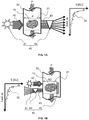
- the figures 1A and 1B schematically represent the measuring principle according to the invention.
- the figure 1A differs from figure 1B by the optical measuring system, which is in a transmissive configuration in the figure 1A and according to a reflective configuration in the figure 1B .
- the present invention allows measurement in situ, that is to say directly in the exhaust line 20 of the gases 10, and without taking gas sample (s) or transforming or preconditioning said gas, typically a gas sample (s). transformation of a non-measurable chemical species into other measurable chemical species for measurement.
- the measurement according to the invention is therefore non-intrusive, and has the advantage of not modifying the flow of the exhaust gases and of being instantaneous, for example with a response time which may be less than 0.1 s, unlike the known methods by gas sampling, in which there is an addition of back pressure, a possible evolution of the gases to be analyzed during sampling, which is unwanted, and a transit of the gases to the measuring cell causing a delay in measurement.
- optical measurement system allowing in situ measurement, can thus be easily carried on board a vehicle, or any other mobile device comprising an exhaust line of exhaust gases from an internal combustion engine.
- the optical measurement system comprises at least a light source 41 and a spectrometer 44.
- the optical system 40 further comprises a reflector 45.
- the UV radiation emitted by the source 41 is reflected by the reflector 45, positioned at the end of the measurement zone 21 opposite to the end where there are located. the light source 41 and the spectrometer 44.
- the reflector 45 is preferably positioned in the exhaust line 20, as illustrated in figure 1B . It can alternatively be integrated into the wall of the exhaust line, or be placed outside the latter.
- the UV radiation 42 passes through the exhaust gases 10 in the measurement zone 21 a first time, is reflected by the reflector 45, passes through the exhaust gases in the measurement zone 21 in the opposite direction a second time, and is then detected by spectrometer 44, as described above.
- the light source 41 and the spectrometer 44 are preferably positioned outside the exhaust line, for example on the external face of the walls of the line, or at a distance from the line if radiation transmission means are provided, such as for example optical fibers as shown in figures 10 and 11 and described below. This allows in particular to prevent damage to these optical elements due to the high temperatures that may be encountered in the exhaust gases.
- the method according to the invention preferably comprises a preliminary step of calibrating the optical measurement system making it possible to obtain a reference digital signal of the light intensity as a function of the wavelength.
- this step consists in emitting the UV radiation through a reference gas, for example a gas containing none of the chemical species to be measured, such as helium, dinitrogen or air, or through a gas. reference which contains certain chemical species that it is desired to measure and of which the concentration in said gas is known.
- the radiation passes through the reference gas, and is then detected by the spectrometer to provide a reference digital signal of light intensity as a function of the wavelength of the portion of the UV radiation that has passed through the reference gas.
- the reference signal is used in the step of estimating the concentration and the temperature, in particular to calculate the absorbance of the exhaust gases, as described in detail below.
- exhaust gas is understood to mean the exhaust gas originating from an internal combustion engine, in particular, but not exclusively, for a motor vehicle. However, this does not in any way rule out all other types of exhaust gas resulting from combustion, such as those from boilers or ovens, and circulating in a chimney or an exhaust duct that can integrate the optical measurement system. described here.
- the present invention can thus be applied to industrial fumes for which it is desired to measure the temperature and the concentration of certain chemical species in gaseous form.
- the UV radiation emitted by the light source 42 has a wavelength between 180 and 400 nm, preferably between 180 and 280 nm, and more preferably between 180 and 240 nm. This wavelength range is part of what is referred to as deep UV.
- the light source can be an LED diode emitting in UV and in particular in deep UV as indicated above, or perhaps a xenon, deuterium or zinc lamp, cadmium, or another gas lamp such as KrBr, KrCL, KrF excimer lamps.
- the spectrometer makes it possible to analyze the light signal in the wavelength range 180-400 nm, preferably 180-280 nm, and more preferably 180-240 nm.
- a simplified system making it possible to analyze a reduced wavelength range can be used.
- the term spectrometer is retained in the present invention to denote such a simplified system.
- the assembly formed by the UV light source and the spectrometer also called an optical sensor in the present invention, is known per se.
- optical sensors can be found commercially.
- the optical sensor can include other elements, in particular optical elements such as lenses making it possible to modify the light beam if necessary (for example convergence or divergence), or even protective elements aiming to protect the light source and the spectrometer, in particular during cold operation of the optical measuring system. Indeed, cold operation can cause deposits on the optical elements by a phenomenon of condensation.
- protective elements are described below, in relation to the figure 12 .
- the position of the sensor installed on the exhaust line can be chosen so as to limit the clogging of the latter.
- the sensor can be positioned at the outlet of a particulate filter (DPF) in the case where the exhaust line includes such a DPF.
- DPF particulate filter
- gaseous chemical species X and preferably several gaseous chemical species X, included in the list consisting in a nonlimiting manner by: NO, NO 2 , N 2 O, NH 3 , BTX, SO 2 , H 2 S, O 3 , O 2 , H 2 O, aldehydes such as acetaldehyde or formaldehyde, non-aromatic hydrocarbons such as acetylene or buta-1,3-diene.
- the measurement is carried out of at least one, and more preferably of several, gaseous chemical species included in the list consisting of: NO, NO 2 , N 2 O, NH 3 , BTX, SO 2 , H 2 S, O 3 , O 2 , H 2 O.
- gaseous chemical species included in the list consisting of: NO, NO 2 , N 2 O, NH 3 , BTX, SO 2 , H 2 S, O 3 , O 2 , H 2 O.
- BTX refers to benzene, toluene and xylenes belonging to the family of aromatic hydrocarbons.
- the dissociated and simultaneous measurement of the concentration of a plurality of these gaseous chemical species can be carried out.
- dissociated measurement is meant an access to the specific concentration of each chemical species, as opposed to an overall measurement of the concentration of several chemical species without distinction, as may be the case for NOx in certain known methods.
- the simultaneous measurement of the concentration of at least two gaseous chemical species preferably at least the concentration of NO and the concentration of NO 2 is carried out .
- Nitrogen oxides, NO and NO 2 represent regulated atmospheric pollutants, which it is advantageous to measure.
- Such a measurement thus allows a control of the NOx at the outlet of a post-combustion pollution control system, preferably at the outlet of an SCR system, or a control of the NOx upstream and downstream of a pollution control system, preferably of an SCR system, for example to estimate the real-time conversion of NOx into N 2 by said depollution system, and while monitoring the supply of NH 3.
- the SCR system makes it possible to selectively reduce NOx by a reducing agent on a dedicated catalyst.
- the reduction is said to be selective because the reducing agent reduces the NOx and not the oxygen present in the mixture to be burned. Thanks to such a pollution control system, the NOx are converted into nitrogen N 2 .
- This reducing agent in particular for use with an internal combustion engine of a motor vehicle, is either ammonia (or a material which can decompose into ammonia), or an oxygenated or non-oxygenated hydrocarbon, or a mixture of hydrocarbons which may contain in part or in whole one or more oxygenated hydrocarbons.
- the ammoniacal agent used is stored either in the form of solid complexes or in the form of a liquid precursor, such as urea in solution. watery.
- the measurement of NO and NO 2 thus makes it possible to control NOx upstream and downstream of an SCR system using an ammoniacal agent, for example to estimate the real-time conversion of NOx into N 2 by said depollution system while controlling NH 3 intake.
- NO / NO 2 ratio because the NOx reduction reaction with ammonia is different depending on this ratio (faster when NO and NO 2 are in equivalent quantities).
- NO 2 is useful for helping the oxidation of soot present in a DPF for example.
- the optical measurement system comprises two optical sensors placed respectively upstream and downstream of the NOx pollution control system, it is then possible to know the real-time conversion of NOx into N 2 .
- a diagnostic system on-board electronics including the diagnosis of NO 2 is then possible, such a diagnosis may be required in the future by the regulations on polluting emissions from internal combustion engines of vehicles rolling.
- the concentration of at least SO 2 , or H 2 S it is also possible to measure the concentration of at least SO 2 , or H 2 S, and preferably at least both.
- the quantification of sulfur elements makes it possible, for example, to diagnose a possible poisoning of a post-combustion depollution system that may be linked to the use of fuels with a high sulfur content, or to control the emissions from ships operating in the area. Controlled Sulfur Emission (SECA).
- SECA Controlled Sulfur Emission
- the concentration of at least NH 3 is measured.
- An ODB including the diagnosis of NH 3 is then possible, such a diagnosis may be required in the future by the regulations on pollutant emissions from internal combustion engines of rolling vehicles.
- the concentration of each chemical species is determined from the optical measurement carried out on the exhaust gases and from the optical signature specific to each chemical species.
- Each gaseous chemical species whose concentration is to be measured absorbs part of the UV radiation and has its own absorption spectrum (absorbance as a function of wavelength).
- the method and the measuring system according to the invention make it possible to access the temperature of the exhaust gases without additional measuring device, conventionally a thermocouple.
- the instantaneous measurement of the temperature which is the result of a specific processing of the UV absorption signal, associated with the measurement of the concentration of gaseous chemical species contained in the gases, provides a clear advantage in the various control strategies. engine, as well as for online evaluation of the efficiency of pollution control systems etc.
- Table 1 below, and the left diagram of the figure 2 illustrate an example of measurement carried out according to the invention.
- the measurement is carried out on a synthetic gas mixture, created from pure gaseous species, and of which the exact concentrations of each of the gaseous species are known.
- Table 1 Exhaust gas Actual values Measured values NH 3 [ppm] 43 37.8 NO [ppm] 226 220 NO 2 [ppm] 257 275 SO 2 [ppm] 20 19.4 O 2 [%] 5.7 6.9 H 2 O [%] 3.6 3.2 Temperature [° C] 105.7 108.3
- the values given in table 2 are estimates made from the measurement on different given synthetic gas mixtures, at various temperature conditions. temperature (at room temperature and at 100 ° C), with an absorbance path of 11 cm. Concentration ranges and accuracy may vary depending on the concentration of gaseous chemical species present in the exhaust gases, temperature, pressure, and the equipment used in the optical measurement system (type of source, spectrometer , other optical elements etc.).
- the measuring range can be adapted by varying the optical path for all gaseous chemical species. In this case, a shorter optical path extends the measuring range but decreases the sensitivity, whereas a larger optical path reduces the measurement range but increases the sensitivity.
- the optical measurement system can be positioned at different locations on the exhaust line to perform an in situ measurement of concentration and temperature suitable for monitoring pollutant emissions upstream and / or downstream of a system. post combustion gas depollution.
- the measurement is performed downstream of at least one exhaust gas depollution system such as a diesel oxidation catalyst (DOC), an SCR system or a DPF.
- DOC diesel oxidation catalyst
- SCR SCR
- DPF DPF
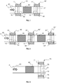
- the exhaust gases 10 circulate in the exhaust line 20 along the path P, on which is placed a pollution control system 60, for example a DOC, an SCR system or a DPF.
- the pollution control system can also be that of a gasoline engine, like a three-way catalyst, another pollution control system conventionally used on my Diesel engines, like a PNA ("partial NOx adsorber" in English) or a NOx trap ("NOx trap" in English). English).
- the depollution system comprises one or more elementary depollution units, each elementary depollution unit possibly being a catalytic bar and / or a filter, catalyzed or not, and modifies the composition or the content of the exhaust gases.
- the optical measurement system 40 is placed downstream of the pollution control system 60.
- the upstream and downstream positions are defined with respect to the direction of flow of the exhaust gases in the exhaust line. Measuring the temperature of the exhaust gases and the concentration of certain chemical species in the exhaust gases downstream of the depollution system 60 makes it possible to check compliance with the emission standards for polluting substances, to monitor their development, and if necessary to adjust the operation of the depollution system to modify the quantities of these substances emitted.
- the in situ measurement is carried out in an identical manner to that of the embodiment shown in figure 4 , except that the optical measurement system includes a reflector 45 for reflective measurement.
- the optical measurement system is that described in relation to the figure 2 .
- the source 41 and the spectrometer 44 are placed on the same side of the exhaust line 20, that is to say at the same end of the measurement zone 21, opposite to that where the reflector 45 is positioned.
- the in situ measurement is carried out upstream of at least one exhaust gas depollution system such as the three systems mentioned above (DOC, SCR, FAP).
- DOC three systems mentioned above
- SCR SCR
- FAP three systems mentioned above
- Such an embodiment is shown schematically on figure 6 , identical to figure 4 with the exception of the optical measurement system 40 positioned upstream of the pollution control system 60.
- Such an embodiment can be useful for obtaining information on the temperature and concentration of chemical species in the exhaust gases before their entry into the exhaust gas. pollution control system, and to use this information to influence, for example, the operation of the pollution control system 60.
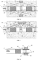
- the in situ measurement is carried out upstream and downstream of at least one exhaust gas depollution system such as the three systems. cited above (DOC, SCR, FAP).
- An example according to this mode is shown in figure 7 , in which two optical measurement systems 40 and 40 'are placed respectively upstream and downstream of a pollution control system 60.
- the second optical measurement system 40' is identical to the first optical measurement system 40 arranged upstream, and comprises a light source 40 'and a light analyzer 44' respectively permitting the emission of UV radiation and the detection and analysis of UV radiation having passed through the exhaust gases in the measurement zone 21 'situated on the line exhaust 20, in order to provide an estimate of the concentration of gaseous chemical species and the temperature of the exhaust gases.
- FIG. 7 Another example according to this mode is illustrated on figure 7 , in which the exhaust line comprises two depollution systems 60 and 61, and three optical measurement systems 40, 40 ', and 40 ", respectively placed upstream of the first depollution system 60, between the depollution systems 60 and 61, and downstream of the pollution control system 61.
- Such an embodiment also makes it possible to know the efficiency of each pollution control system on the exhaust line, and to optionally adjust the pollution control system as a function of the information. of concentration and temperature obtained upstream, downstream and between the pollution control systems, in order to control the polluting emissions at the outlet of the exhaust line.
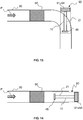
- the UV light source and / or the spectrometer of the optical measurement system is connected to the exhaust line by an optical fiber, allowing more flexibility in the integration of the optical measurement system into the line. exhaust, in particular in the context of an on-board system of a vehicle.
- An example of such an embodiment is shown in the figure 9 , where optical fibers 75 and 76 respectively connect the light source 71 and the spectrometer 74 of the optical measurement system 70 to the exhaust line 20, at the level of the measurement zone 21 where the exhaust gases are crossed by UV radiation conducted by optical fibers 75 and 76.
- the optical system may be that described in relation to the figure 2 , comprising a reflector 45.
- the optical measurement system comprises several measurement zones connected to a single light source and a single spectrometer, by means of optical fibers.
- Such an embodiment makes it possible, for example, to reduce the cost of implementation of optical measurement in the event that measurements upstream and downstream of pollution control systems are desired.
- An example of such an embodiment is illustrated in the figure 10 , in which the optical measurement system 80 comprises three measurement zones 21, 22 and 23, and a single lighting system 81 and detection / analysis 84 connected to the measurement zones by optical fibers 85, 87 and 88.
- the in situ measurement is carried out in an identical manner to that of the embodiment shown in figure 10 , except that the optical measuring system comprises three reflectors 45, 45 'and 45 "as described in relation to the figure 2 , respectively arranged at the ends of the measurement zones 21, 22 and 23.
- the optical measuring system 90 comprises means 95 for protecting the light source 91 and / or the spectrometer 94.
- Such protection means are useful for example during cold operation of the optical measuring system, in order to prevent clogging of the optical elements, as already explained above.
- These protection means may comprise a flap that can be controlled by measuring the temperature of the exhaust gases, an air barrier between the light source 91 or the spectrometer 94 and the exhaust gases passing through the measurement zone 21, a specific coating, for example for thermal insulation or to prevent the adhesion of liquid or solid particles, of the surface or surfaces separating the light source 91 from the exhaust gases or the spectrometer 94 from the exhaust gases, or a means for heating said surfaces. It may also be a specific geometry of the optical sensor, not shown in the figure. figure 12 .
- the optical measuring system 90 is of the type shown in figure 2 , and the optical path is UV radiation is substantially tangent to the path P of the exhaust gases, the optical system being for example positioned at an elbow of the exhaust line 20.
- the optical measuring system 90 is of the type shown in figure 2 , and the optical path is UV radiation is substantially parallel to the path P of the exhaust gases.
- the light source 91 and spectrometer 94 assembly are located at the outlet of the exhaust line.
- the present invention advantageously applies to the monitoring of polluting emissions of exhaust gases from an internal combustion engine in the field of transport, in particular that of rolling vehicles, but also to the monitoring of polluting emissions in the case of an internal combustion engine.
- stationary applications such as industrial fumes from combustion plants.
- the present invention can be used to monitor post-combustion pollution control systems, and optionally control, that is to say intervene in the adjustment, of such pollution control systems.
- the present invention can also be applied to the field of monitoring polluting emissions of exhaust gases from an internal combustion engine of ships, in particular monitoring of NOx in controlled emission zones (ECA), in addition to SOx monitoring in Controlled Sulfur Emission Zones (SECA).
- ECA controlled emission zones
- SECA Controlled Sulfur Emission Zones
Landscapes
- Engineering & Computer Science (AREA)
- Chemical & Material Sciences (AREA)
- Combustion & Propulsion (AREA)
- Physics & Mathematics (AREA)
- General Engineering & Computer Science (AREA)
- Mechanical Engineering (AREA)
- Spectroscopy & Molecular Physics (AREA)
- Analytical Chemistry (AREA)
- General Physics & Mathematics (AREA)
- Immunology (AREA)
- General Health & Medical Sciences (AREA)
- Health & Medical Sciences (AREA)
- Pathology (AREA)
- Chemical Kinetics & Catalysis (AREA)
- Biochemistry (AREA)
- Life Sciences & Earth Sciences (AREA)
- Investigating Or Analysing Materials By Optical Means (AREA)
- Measuring Temperature Or Quantity Of Heat (AREA)
- Testing Of Engines (AREA)
Claims (17)
- Verfahren zur In-situ-Messung der Konzentration([X]) mindestens einer gasförmigen chemischen Spezies, die in Abgasen (10) enthalten ist, die in einer Auspuffanlage (20) zirkulieren, und der Temperatur (T) der Abgase mittels eines optischen Messsystems (40, 40', 40", 70, 80, 90), wobei das optische Messsystem mindestens eine Lichtquelle (41, 41', 41", 71, 81, 91) und ein Spektrometer (44, 44', 44", 74, 84, 94) aufweist, umfassend die folgenden Schritte:- das Emittieren, durch die Lichtquelle, einer UV-Strahlung (42) durch die Abgase hindurch in einem Messbereich (21, 22, 23), der in der Auspuffanlage (20) gelegen ist;- das Detektieren, durch das Spektrometer, mindestens eines Teils der UV-Strahlung, der die Abgase (43) durchdrungen hat, in dem Messbereich (21, 22, 23) und das Erzeugen eines digitalen Signals der Lichtstärke (50) in Abhängigkeit von der Wellenlänge (W) des Teils der UV-Strahlung, der die Abgase durchdrungen hat;- das Schätzen der Konzentration ([X]) der chemischen Spezies und der Temperatur (T) der Abgase anhand des digitalen Signals (50).
- Verfahren nach Anspruch 1, bei dem das optische Messsystem ferner einen Reflektor (45, 45', 45") aufweist und das Verfahren einen Schritt umfasst, bei dem die von der Lichtquelle (41) emittierte UV-Strahlung (42) die Abgase in dem Messbereich (21) durchdringt, um anschließend von dem Reflektor (45, 45', 45") reflektiert zu werden, die Abgase in dem Messbereich (21) erneut in Gegenrichtung durchdringt, um anschließend von dem Spektrometer (44) detektiert zu werden.
- Verfahren nach einem der Ansprüche 1 oder 2, umfassend einen vorherigen Schritt des Kalibrierens des optischen Messsystems, um ein digitales Referenzsignal der Lichtstärke in Abhängigkeit von der Wellenlänge auszugeben, bevorzugt durch Emittieren der UV-Strahlung durch ein Referenzgas hindurch, beispielsweise ein Referenzgas, das keine der zu messenden chemischen Spezies enthält, und durch Detektieren mindestens eines Teils der UV-Strahlung, der das Referenzgas durchdrungen hat, um ein digitales Referenzsignal der Lichtstärke in Abhängigkeit von der Wellenlänge des Teils der UV-Strahlung, der das Referenzgas durchdrungen hat, auszugeben.
- Verfahren nach einem der vorhergehenden Ansprüche, bei dem der Schritt des Schätzens der Konzentration ([X]) der chemischen Spezies und der Temperatur (T) der Abgase (10) umfasst:- das Bestimmen der Absorbanz (A) der Abgase in Abhängigkeit von der Wellenlänge anhand des digitalen Signals der Lichtstärke (50) in Abhängigkeit von der Wellenlänge des Teils der UV-Strahlung, der die Abgase (43) durchdrungen hat, und eines digitalen Referenzsignals;- das Bestimmen der Konzentration ([X]) der mindestens einen chemischen Spezies anhand der Absorbanz der Abgase und von vorbestimmten Absorbanz-, Temperatur- und Druckmerkmalen der chemischen Spezies;- das Bestimmen der Temperatur (T) der Abgase durch Ändern des molaren Extinktionskoeffizienten der Absorbanz der chemischen Spezies, die aus der Absorbanz der Abgase extrahiert wird, wobei die Änderung ein Versatz der Wellenlänge oder eine Änderung der Amplitude oder eine Kombination der beiden ist.
- Verfahren nach Anspruch 4, bei dem die Absorbanz (A) der Abgase (10) eine Funktion der Absorbanzlänge, der Dichtezahl der Moleküle der chemischen Spezies und des molaren Extinktionskoeffizienten ist.
- Verfahren nach einem der vorhergehenden Ansprüche, bei dem die emittierte UV-Strahlung (42) eine Wellenlänge zwischen 180 und 400 nm, bevorzugt zwischen 180 und 280 nm und noch bevorzugter zwischen 180 und 240 nm hat.
- Verfahren nach einem der vorhergehenden Ansprüche, bei dem die Konzentration von mindestens einer und bevorzugt von mehreren gasförmigen chemischen Spezies gemessen wird, die in den Abgasen enthalten sind und in der Liste inbegriffen sind, die gebildet wird durch: NO, NO2, N2O, BTX, SO2, H2S, O3, O2, H2O, Aldehyde wie Acetaldehyd oder Formaldehyd, nicht aromatische Kohlenwasserstoffe wie Acetylen oder Buta-1,3-dien.
- Verfahren nach einem der vorhergehenden Ansprüche, bei dem gleichzeitig die Konzentration von mindestens zwei gasförmigen chemischen Spezies gemessen wird und bevorzugt mindestens die NO-Konzentration und die NO2-Konzentration.
- Verfahren nach Anspruch 7, angewandt auf die Kontrolle der NOx am Ausgang eines Reinigungssystems (60, 61), bevorzugt am Ausgang eines Systems zur selektiven katalytischen Reduktion (SCR), oder auf die Kontrolle der NOx stromauf und stromab eines Reinigungssystems (60, 61), bei dem mindestens die NO-Konzentration und die NO2-Konzentration gemessen werden, bevorzugt zum Schätzen der Umwandlung der NOx in N2 durch das Reinigungssystem in Echtzeit.
- Verfahren nach einem der vorhergehenden Ansprüche, bei dem die Konzentration mindestens einer gasförmigen chemischen Spezies, die unter den schwefelhaltigen chemischen Spezies SO2 und H2S ausgewählt ist, und bevorzugt von beiden gemessen wird.
- Verfahren nach einem der vorhergehenden Ansprüche, bei dem die Konzentration mindestens von NH3 gemessen wird.
- Verfahren nach Anspruch 11, angewandt auf die Kontrolle von NH3 stromauf und stromab eines Systems zur selektiven katalytischen Reduktion (SCR), bei dem der Verlauf der NH3-Konzentration stromauf und stromab des Systems zur selektiven katalytischen Reduktion (SCR) überwacht wird.
- Verfahren nach einem der vorhergehenden Ansprüche, bei dem die Abgase aus einem Verbrennungsmotor stammen.
- Verfahren nach einem der vorhergehenden Ansprüche, bei dem die UV-Strahlung die Abgase gemäß einem optischen Pfad durchdringt, der im Wesentlichen senkrecht zum Weg (P) der Abgase verläuft.
- Verfahren nach einem der vorhergehenden Ansprüche, bei dem die In-situ-Messung stromab mindestens eines Reinigungssystems (60, 61) der Abgase wie eines Dieseloxidationskatalysators (DOC), eines Systems zur selektiven katalytischen Reduktion (SCR) oder eines Partikelfilters (FAP) durchgeführt wird.
- Verfahren nach einem der vorhergehenden Ansprüche, bei dem die In-situ-Messung stromauf mindestens eines Reinigungssystems (60, 61) der Abgase wie eines Dieseloxidationskatalysators (DOC), eines Systems zur selektiven katalytischen Reduktion (SCR) oder eines Partikelfilters (FAP) durchgeführt wird.
- Optisches Messsystem (40, 40', 40", 70, 80, 90) zur In-situ-Messung der Konzentration ([X]) mindestens einer gasförmigen chemischen Spezies, die in Abgasen (10) enthalten ist, die in einer Auspuffanlage (20) zirkulieren, und der Temperatur (T) der Abgase nach einem der vorhergehenden Ansprüche, wobei das System aufweist:- eine Lichtquelle (41, 41', 41", 71, 81, 91), die geeignet ist, eine UV-Strahlung (42) durch die Abgase hindurch in einem in der Auspuffanlage gelegenen Messbereich (21, 22, 23) zu emittieren, wobei die Lichtquelle bevorzugt so angeordnet ist, dass sie die UV-Strahlung gemäß einem optischen Pfad emittiert, der im Wesentlichen senkrecht zum Weg (P) der Abgase verläuft;- ein Spektrometer (44, 44', 44", 74, 84, 94), das geeignet ist, mindestens einen Teil der UV-Strahlung, der die Abgase (43) durchdrungen hat, in dem Messbereich (21, 22, 23) zu detektieren, und das Erzeugen eines digitalen Signals der Lichtstärke (50) in Abhängigkeit von der Wellenlänge (W) des Teils der UV-Strahlung, der die Abgase (43) durchdrungen hat;- Mittel zur Analyse und Verarbeitung des Signals, um die Konzentration ([X]) der chemischen Spezies und die Temperatur (T) der Abgase anhand des digitalen Signals (50) zu bestimmen.
Applications Claiming Priority (2)
| Application Number | Priority Date | Filing Date | Title |
|---|---|---|---|
| FR1757140A FR3069641B1 (fr) | 2017-07-27 | 2017-07-27 | Procede et systeme de mesure optique de la concentration d’especes gazeuses de gaz d’echappement |
| PCT/EP2018/067930 WO2019020326A1 (fr) | 2017-07-27 | 2018-07-03 | Procede et systeme de mesure optique de la concentration d'especes gazeuses de gaz d'echappement |
Publications (2)
| Publication Number | Publication Date |
|---|---|
| EP3658895A1 EP3658895A1 (de) | 2020-06-03 |
| EP3658895B1 true EP3658895B1 (de) | 2021-06-09 |
Family
ID=60138509
Family Applications (1)
| Application Number | Title | Priority Date | Filing Date |
|---|---|---|---|
| EP18737870.8A Active EP3658895B1 (de) | 2017-07-27 | 2018-07-03 | Verfahren und vorrichtung zur optischen bemessung der konzentration chemischer spezies in einem abgas |
Country Status (4)
| Country | Link |
|---|---|
| EP (1) | EP3658895B1 (de) |
| JP (1) | JP7169339B2 (de) |
| FR (1) | FR3069641B1 (de) |
| WO (1) | WO2019020326A1 (de) |
Families Citing this family (7)
| Publication number | Priority date | Publication date | Assignee | Title |
|---|---|---|---|---|
| US11137382B2 (en) * | 2018-06-15 | 2021-10-05 | Morgan Schaffer Ltd. | Apparatus and method for performing gas analysis using optical absorption spectroscopy, such as infrared (IR) and/or UV, and use thereof in apparatus and method for performing dissolved gas analysis (DGA) on a piece of electrical equipment |
| FR3092665B1 (fr) * | 2019-02-07 | 2024-08-02 | Ifp Energies Now | Procede pour la mesure de la concentration en especes gazeuses dans un biogaz |
| FR3107594B1 (fr) | 2020-02-25 | 2022-10-21 | Ifp Energies Now | Procede et systeme pour la mesure optique d'une caracteristique de particules presentes dans un milieu gazeux |
| JP7518644B2 (ja) * | 2020-03-26 | 2024-07-18 | 株式会社オーク製作所 | オゾン生成装置、オゾン生成方法および窒素酸化物検出方法 |
| KR102309680B1 (ko) * | 2021-05-10 | 2021-10-08 | 국방과학연구소 | 주성분 분석 기법을 이용한 초분광 영상 실시간 독성 화학가스 탐지 방법 및 이를 실행시키기 위한 프로그램을 기록한 컴퓨터 판독 가능한 기록 매체 |
| FR3143760A1 (fr) | 2022-12-19 | 2024-06-21 | IFP Energies Nouvelles | Dispositif et procédé pour quantifier une teneur en azote total présent dans un échantillon d’un milieu poreux et/ou issu de la biomasse |
| FR3151400A1 (fr) | 2023-07-20 | 2025-01-24 | IFP Energies Nouvelles | Procede pour la mesure de la concentration en un compose chimique contenu dans un fluide, au moyen d’un systeme de mesure optique |
Family Cites Families (12)
| Publication number | Priority date | Publication date | Assignee | Title |
|---|---|---|---|---|
| FR2533316A1 (fr) * | 1982-09-22 | 1984-03-23 | Inst Francais Du Petrole | Methode et dispositifs a reponse rapide permettant de deceler une mauvaise combustion |
| JP2003014627A (ja) | 2001-06-28 | 2003-01-15 | Ishikawajima Harima Heavy Ind Co Ltd | 多成分分析計の検量線作成方法 |
| JP2004093419A (ja) | 2002-08-30 | 2004-03-25 | Ishikawajima Harima Heavy Ind Co Ltd | No濃度定量測定方法 |
| JP2004138467A (ja) | 2002-10-17 | 2004-05-13 | Horiba Ltd | 紫外線吸収式測定装置および測定試料の処理方法 |
| ITBA20030066A1 (it) * | 2003-12-22 | 2005-06-23 | I N F M Istituto Naz Per La Fisica Della Ma | Sistema ottico di rivelazione della concentrazione di prodotti di combustione |
| US8208143B2 (en) * | 2005-04-28 | 2012-06-26 | Toyota Jidosha Kabushiki Kaisha | Exhaust gas analyzer |
| DE102005060245B3 (de) * | 2005-12-14 | 2007-03-01 | Deutsches Zentrum für Luft- und Raumfahrt e.V. | Verfahren zur Bestimmung von Konzentrations-, Druck- und Temperaturprofilen von Gasen in Verbrennungsprozessen und deren Abgasströmen und -wolken |
| JP4199766B2 (ja) * | 2005-12-16 | 2008-12-17 | トヨタ自動車株式会社 | 排ガス分析方法および排ガス分析装置 |
| JP5297215B2 (ja) | 2009-01-30 | 2013-09-25 | 三菱重工業株式会社 | 排ガス浄化装置 |
| DE102010001443A1 (de) | 2010-02-01 | 2011-08-04 | Robert Bosch GmbH, 70469 | Optischer Gassensor |
| FR2993602B1 (fr) | 2012-07-17 | 2014-07-25 | IFP Energies Nouvelles | Procede de detection de composes azotes contenus dans des gaz d'echappement, notamment de moteur a combustion interne |
| US9671351B2 (en) * | 2014-04-24 | 2017-06-06 | Stmicroelectronics S.R.L. | Multi-sensor optical device for detecting chemical species and manufacturing method thereof |
-
2017
- 2017-07-27 FR FR1757140A patent/FR3069641B1/fr not_active Expired - Fee Related
-
2018
- 2018-07-03 WO PCT/EP2018/067930 patent/WO2019020326A1/fr not_active Ceased
- 2018-07-03 JP JP2020504175A patent/JP7169339B2/ja active Active
- 2018-07-03 EP EP18737870.8A patent/EP3658895B1/de active Active
Also Published As
| Publication number | Publication date |
|---|---|
| FR3069641A1 (fr) | 2019-02-01 |
| JP2020528151A (ja) | 2020-09-17 |
| EP3658895A1 (de) | 2020-06-03 |
| JP7169339B2 (ja) | 2022-11-10 |
| WO2019020326A1 (fr) | 2019-01-31 |
| FR3069641B1 (fr) | 2019-07-19 |
Similar Documents
| Publication | Publication Date | Title |
|---|---|---|
| EP3658895B1 (de) | Verfahren und vorrichtung zur optischen bemessung der konzentration chemischer spezies in einem abgas | |
| Carslaw et al. | The diminishing importance of nitrogen dioxide emissions from road vehicle exhaust | |
| US9194273B2 (en) | Apparatus, system, and method for aftertreatment control and diagnostics | |
| CN1253624A (zh) | 遥测废气的方法及装置 | |
| US20180321138A1 (en) | Optical exhaust gas detection assembly with remote mounted electronics | |
| US8223337B2 (en) | Apparatus, system, and method for aftertreatment control and diagnostics | |
| Ahari et al. | Impact of SCR integration on N 2 O emissions in diesel application | |
| Nakashima et al. | Nitrous acid (HONO) emission factors for diesel vehicles determined using a chassis dynamometer | |
| EP4111165B1 (de) | Verfahren und system zur optischen messung einer eigenschaft von partikeln in einem gasförmigen medium | |
| Marjanen et al. | Exhaust emissions from a prototype non-road natural gas engine | |
| Dooly et al. | Low concentration monitoring of exhaust gases using a UV-based optical sensor | |
| Yamamoto et al. | Real-time measurement of nitrogen dioxide in vehicle exhaust gas by mid-infrared cavity ring-down spectroscopy | |
| Dooly et al. | Deep UV based DOAS system for the monitoring of nitric oxide using ratiometric separation techniques | |
| Kasyutich et al. | In situ vehicle engine exhaust measurements of nitric oxide with a thermoelectrically cooled, cw DFB quantum cascade laser | |
| WO2020160880A1 (fr) | Procede pour la mesure de la concentration en especes gazeuses dans un biogaz | |
| Sutela et al. | Fast response CO2 sensor for automotive exhaust gas analysis | |
| WO2025016729A1 (fr) | Procede pour la mesure de la concentration en un compose chimique contenu dans un fluide, au moyen d'un systeme de mesure optique | |
| EP1747359B1 (de) | Verfahren und vorrichtung zum schätzen des thermischen zustands einer im abgassystem einer brennkraftmaschine installierten katalytischen stickoxidfalle | |
| Dooly et al. | Optical sensing of hazardous exhaust emissions using a UV based extrinsic sensor | |
| Montajir | Development of an ultra-low concentration N2O analyzer using quantum cascade laser (QCL) | |
| Vojtíšek et al. | 2.26 Portable, on-board FTIR spectrometers: A universal tool for real-world monitoring of greenhouse gases, reactive nitrogen compounds, and other gaseous pollutants | |
| Hara et al. | Development of nitrogen components analyzer utilizing quantum cascade laser | |
| Li et al. | Ammonia Measurement Investigation Using Quantum Cascade Laser and Two Different Fourier Transform Infrared Spectroscopy Methods | |
| Degner et al. | Low-cost sensor for online detection of harmful diesel combustion gases in UV-VIS region | |
| Li et al. | Tuneable diode laser spectroscopy correction factor investigation on ammonia measurement |
Legal Events
| Date | Code | Title | Description |
|---|---|---|---|
| STAA | Information on the status of an ep patent application or granted ep patent |
Free format text: STATUS: UNKNOWN |
|
| STAA | Information on the status of an ep patent application or granted ep patent |
Free format text: STATUS: THE INTERNATIONAL PUBLICATION HAS BEEN MADE |
|
| PUAI | Public reference made under article 153(3) epc to a published international application that has entered the european phase |
Free format text: ORIGINAL CODE: 0009012 |
|
| STAA | Information on the status of an ep patent application or granted ep patent |
Free format text: STATUS: REQUEST FOR EXAMINATION WAS MADE |
|
| 17P | Request for examination filed |
Effective date: 20200227 |
|
| AK | Designated contracting states |
Kind code of ref document: A1 Designated state(s): AL AT BE BG CH CY CZ DE DK EE ES FI FR GB GR HR HU IE IS IT LI LT LU LV MC MK MT NL NO PL PT RO RS SE SI SK SM TR |
|
| AX | Request for extension of the european patent |
Extension state: BA ME |
|
| DAV | Request for validation of the european patent (deleted) | ||
| DAX | Request for extension of the european patent (deleted) | ||
| RIC1 | Information provided on ipc code assigned before grant |
Ipc: G01M 15/10 20060101ALI20201203BHEP Ipc: F01N 11/00 20060101ALI20201203BHEP Ipc: G01N 21/33 20060101AFI20201203BHEP |
|
| GRAP | Despatch of communication of intention to grant a patent |
Free format text: ORIGINAL CODE: EPIDOSNIGR1 |
|
| STAA | Information on the status of an ep patent application or granted ep patent |
Free format text: STATUS: GRANT OF PATENT IS INTENDED |
|
| INTG | Intention to grant announced |
Effective date: 20210120 |
|
| GRAS | Grant fee paid |
Free format text: ORIGINAL CODE: EPIDOSNIGR3 |
|
| GRAA | (expected) grant |
Free format text: ORIGINAL CODE: 0009210 |
|
| STAA | Information on the status of an ep patent application or granted ep patent |
Free format text: STATUS: THE PATENT HAS BEEN GRANTED |
|
| AK | Designated contracting states |
Kind code of ref document: B1 Designated state(s): AL AT BE BG CH CY CZ DE DK EE ES FI FR GB GR HR HU IE IS IT LI LT LU LV MC MK MT NL NO PL PT RO RS SE SI SK SM TR |
|
| REG | Reference to a national code |
Ref country code: GB Ref legal event code: FG4D Free format text: NOT ENGLISH |
|
| REG | Reference to a national code |
Ref country code: CH Ref legal event code: EP Ref country code: AT Ref legal event code: REF Ref document number: 1400916 Country of ref document: AT Kind code of ref document: T Effective date: 20210615 |
|
| REG | Reference to a national code |
Ref country code: DE Ref legal event code: R096 Ref document number: 602018018436 Country of ref document: DE |
|
| REG | Reference to a national code |
Ref country code: IE Ref legal event code: FG4D Free format text: LANGUAGE OF EP DOCUMENT: FRENCH |
|
| REG | Reference to a national code |
Ref country code: LT Ref legal event code: MG9D |
|
| PG25 | Lapsed in a contracting state [announced via postgrant information from national office to epo] |
Ref country code: FI Free format text: LAPSE BECAUSE OF FAILURE TO SUBMIT A TRANSLATION OF THE DESCRIPTION OR TO PAY THE FEE WITHIN THE PRESCRIBED TIME-LIMIT Effective date: 20210609 Ref country code: HR Free format text: LAPSE BECAUSE OF FAILURE TO SUBMIT A TRANSLATION OF THE DESCRIPTION OR TO PAY THE FEE WITHIN THE PRESCRIBED TIME-LIMIT Effective date: 20210609 Ref country code: LT Free format text: LAPSE BECAUSE OF FAILURE TO SUBMIT A TRANSLATION OF THE DESCRIPTION OR TO PAY THE FEE WITHIN THE PRESCRIBED TIME-LIMIT Effective date: 20210609 Ref country code: BG Free format text: LAPSE BECAUSE OF FAILURE TO SUBMIT A TRANSLATION OF THE DESCRIPTION OR TO PAY THE FEE WITHIN THE PRESCRIBED TIME-LIMIT Effective date: 20210909 |
|
| REG | Reference to a national code |
Ref country code: AT Ref legal event code: MK05 Ref document number: 1400916 Country of ref document: AT Kind code of ref document: T Effective date: 20210609 |
|
| REG | Reference to a national code |
Ref country code: NL Ref legal event code: MP Effective date: 20210609 |
|
| PG25 | Lapsed in a contracting state [announced via postgrant information from national office to epo] |
Ref country code: NO Free format text: LAPSE BECAUSE OF FAILURE TO SUBMIT A TRANSLATION OF THE DESCRIPTION OR TO PAY THE FEE WITHIN THE PRESCRIBED TIME-LIMIT Effective date: 20210909 Ref country code: LV Free format text: LAPSE BECAUSE OF FAILURE TO SUBMIT A TRANSLATION OF THE DESCRIPTION OR TO PAY THE FEE WITHIN THE PRESCRIBED TIME-LIMIT Effective date: 20210609 Ref country code: RS Free format text: LAPSE BECAUSE OF FAILURE TO SUBMIT A TRANSLATION OF THE DESCRIPTION OR TO PAY THE FEE WITHIN THE PRESCRIBED TIME-LIMIT Effective date: 20210609 Ref country code: SE Free format text: LAPSE BECAUSE OF FAILURE TO SUBMIT A TRANSLATION OF THE DESCRIPTION OR TO PAY THE FEE WITHIN THE PRESCRIBED TIME-LIMIT Effective date: 20210609 Ref country code: GR Free format text: LAPSE BECAUSE OF FAILURE TO SUBMIT A TRANSLATION OF THE DESCRIPTION OR TO PAY THE FEE WITHIN THE PRESCRIBED TIME-LIMIT Effective date: 20210910 |
|
| PG25 | Lapsed in a contracting state [announced via postgrant information from national office to epo] |
Ref country code: ES Free format text: LAPSE BECAUSE OF FAILURE TO SUBMIT A TRANSLATION OF THE DESCRIPTION OR TO PAY THE FEE WITHIN THE PRESCRIBED TIME-LIMIT Effective date: 20210609 Ref country code: EE Free format text: LAPSE BECAUSE OF FAILURE TO SUBMIT A TRANSLATION OF THE DESCRIPTION OR TO PAY THE FEE WITHIN THE PRESCRIBED TIME-LIMIT Effective date: 20210609 Ref country code: SK Free format text: LAPSE BECAUSE OF FAILURE TO SUBMIT A TRANSLATION OF THE DESCRIPTION OR TO PAY THE FEE WITHIN THE PRESCRIBED TIME-LIMIT Effective date: 20210609 Ref country code: CZ Free format text: LAPSE BECAUSE OF FAILURE TO SUBMIT A TRANSLATION OF THE DESCRIPTION OR TO PAY THE FEE WITHIN THE PRESCRIBED TIME-LIMIT Effective date: 20210609 Ref country code: AT Free format text: LAPSE BECAUSE OF FAILURE TO SUBMIT A TRANSLATION OF THE DESCRIPTION OR TO PAY THE FEE WITHIN THE PRESCRIBED TIME-LIMIT Effective date: 20210609 Ref country code: SM Free format text: LAPSE BECAUSE OF FAILURE TO SUBMIT A TRANSLATION OF THE DESCRIPTION OR TO PAY THE FEE WITHIN THE PRESCRIBED TIME-LIMIT Effective date: 20210609 Ref country code: RO Free format text: LAPSE BECAUSE OF FAILURE TO SUBMIT A TRANSLATION OF THE DESCRIPTION OR TO PAY THE FEE WITHIN THE PRESCRIBED TIME-LIMIT Effective date: 20210609 Ref country code: PT Free format text: LAPSE BECAUSE OF FAILURE TO SUBMIT A TRANSLATION OF THE DESCRIPTION OR TO PAY THE FEE WITHIN THE PRESCRIBED TIME-LIMIT Effective date: 20211011 Ref country code: NL Free format text: LAPSE BECAUSE OF FAILURE TO SUBMIT A TRANSLATION OF THE DESCRIPTION OR TO PAY THE FEE WITHIN THE PRESCRIBED TIME-LIMIT Effective date: 20210609 |
|
| PG25 | Lapsed in a contracting state [announced via postgrant information from national office to epo] |
Ref country code: PL Free format text: LAPSE BECAUSE OF FAILURE TO SUBMIT A TRANSLATION OF THE DESCRIPTION OR TO PAY THE FEE WITHIN THE PRESCRIBED TIME-LIMIT Effective date: 20210609 |
|
| REG | Reference to a national code |
Ref country code: CH Ref legal event code: PL |
|
| REG | Reference to a national code |
Ref country code: DE Ref legal event code: R097 Ref document number: 602018018436 Country of ref document: DE |
|
| PG25 | Lapsed in a contracting state [announced via postgrant information from national office to epo] |
Ref country code: MC Free format text: LAPSE BECAUSE OF FAILURE TO SUBMIT A TRANSLATION OF THE DESCRIPTION OR TO PAY THE FEE WITHIN THE PRESCRIBED TIME-LIMIT Effective date: 20210609 |
|
| REG | Reference to a national code |
Ref country code: BE Ref legal event code: MM Effective date: 20210731 |
|
| PLBE | No opposition filed within time limit |
Free format text: ORIGINAL CODE: 0009261 |
|
| STAA | Information on the status of an ep patent application or granted ep patent |
Free format text: STATUS: NO OPPOSITION FILED WITHIN TIME LIMIT |
|
| PG25 | Lapsed in a contracting state [announced via postgrant information from national office to epo] |
Ref country code: LI Free format text: LAPSE BECAUSE OF NON-PAYMENT OF DUE FEES Effective date: 20210731 Ref country code: DK Free format text: LAPSE BECAUSE OF FAILURE TO SUBMIT A TRANSLATION OF THE DESCRIPTION OR TO PAY THE FEE WITHIN THE PRESCRIBED TIME-LIMIT Effective date: 20210609 Ref country code: CH Free format text: LAPSE BECAUSE OF NON-PAYMENT OF DUE FEES Effective date: 20210731 |
|
| 26N | No opposition filed |
Effective date: 20220310 |
|
| PG25 | Lapsed in a contracting state [announced via postgrant information from national office to epo] |
Ref country code: LU Free format text: LAPSE BECAUSE OF NON-PAYMENT OF DUE FEES Effective date: 20210703 Ref country code: AL Free format text: LAPSE BECAUSE OF FAILURE TO SUBMIT A TRANSLATION OF THE DESCRIPTION OR TO PAY THE FEE WITHIN THE PRESCRIBED TIME-LIMIT Effective date: 20210609 |
|
| PG25 | Lapsed in a contracting state [announced via postgrant information from national office to epo] |
Ref country code: IE Free format text: LAPSE BECAUSE OF NON-PAYMENT OF DUE FEES Effective date: 20210703 Ref country code: BE Free format text: LAPSE BECAUSE OF NON-PAYMENT OF DUE FEES Effective date: 20210731 |
|
| PG25 | Lapsed in a contracting state [announced via postgrant information from national office to epo] |
Ref country code: CY Free format text: LAPSE BECAUSE OF FAILURE TO SUBMIT A TRANSLATION OF THE DESCRIPTION OR TO PAY THE FEE WITHIN THE PRESCRIBED TIME-LIMIT Effective date: 20210609 |
|
| PG25 | Lapsed in a contracting state [announced via postgrant information from national office to epo] |
Ref country code: HU Free format text: LAPSE BECAUSE OF FAILURE TO SUBMIT A TRANSLATION OF THE DESCRIPTION OR TO PAY THE FEE WITHIN THE PRESCRIBED TIME-LIMIT; INVALID AB INITIO Effective date: 20180703 |
|
| PG25 | Lapsed in a contracting state [announced via postgrant information from national office to epo] |
Ref country code: MK Free format text: LAPSE BECAUSE OF FAILURE TO SUBMIT A TRANSLATION OF THE DESCRIPTION OR TO PAY THE FEE WITHIN THE PRESCRIBED TIME-LIMIT Effective date: 20210609 |
|
| PG25 | Lapsed in a contracting state [announced via postgrant information from national office to epo] |
Ref country code: MT Free format text: LAPSE BECAUSE OF FAILURE TO SUBMIT A TRANSLATION OF THE DESCRIPTION OR TO PAY THE FEE WITHIN THE PRESCRIBED TIME-LIMIT Effective date: 20210609 |
|
| PGFP | Annual fee paid to national office [announced via postgrant information from national office to epo] |
Ref country code: DE Payment date: 20250728 Year of fee payment: 8 |
|
| PGFP | Annual fee paid to national office [announced via postgrant information from national office to epo] |
Ref country code: IT Payment date: 20250721 Year of fee payment: 8 |
|
| PGFP | Annual fee paid to national office [announced via postgrant information from national office to epo] |
Ref country code: GB Payment date: 20250722 Year of fee payment: 8 |
|
| PGFP | Annual fee paid to national office [announced via postgrant information from national office to epo] |
Ref country code: FR Payment date: 20250725 Year of fee payment: 8 |
|
| PG25 | Lapsed in a contracting state [announced via postgrant information from national office to epo] |
Ref country code: TR Free format text: LAPSE BECAUSE OF FAILURE TO SUBMIT A TRANSLATION OF THE DESCRIPTION OR TO PAY THE FEE WITHIN THE PRESCRIBED TIME-LIMIT Effective date: 20210609 |