EP3658869B1 - Temperaturkompensationsvorrichtung und elektrooptischer wandler mit einer solchen vorrichtung - Google Patents
Temperaturkompensationsvorrichtung und elektrooptischer wandler mit einer solchen vorrichtung Download PDFInfo
- Publication number
- EP3658869B1 EP3658869B1 EP18740871.1A EP18740871A EP3658869B1 EP 3658869 B1 EP3658869 B1 EP 3658869B1 EP 18740871 A EP18740871 A EP 18740871A EP 3658869 B1 EP3658869 B1 EP 3658869B1
- Authority
- EP
- European Patent Office
- Prior art keywords
- length
- variation
- terminal
- holder
- bars
- Prior art date
- Legal status (The legal status is an assumption and is not a legal conclusion. Google has not performed a legal analysis and makes no representation as to the accuracy of the status listed.)
- Active
Links
Images

Classifications
-
- G—PHYSICS
- G01—MEASURING; TESTING
- G01H—MEASUREMENT OF MECHANICAL VIBRATIONS OR ULTRASONIC, SONIC OR INFRASONIC WAVES
- G01H9/00—Measuring mechanical vibrations or ultrasonic, sonic or infrasonic waves by using radiation-sensitive means, e.g. optical means
- G01H9/004—Measuring mechanical vibrations or ultrasonic, sonic or infrasonic waves by using radiation-sensitive means, e.g. optical means using fibre optic sensors
-
- H—ELECTRICITY
- H01—ELECTRIC ELEMENTS
- H01S—DEVICES USING THE PROCESS OF LIGHT AMPLIFICATION BY STIMULATED EMISSION OF RADIATION [LASER] TO AMPLIFY OR GENERATE LIGHT; DEVICES USING STIMULATED EMISSION OF ELECTROMAGNETIC RADIATION IN WAVE RANGES OTHER THAN OPTICAL
- H01S3/00—Lasers, i.e. devices using stimulated emission of electromagnetic radiation in the infrared, visible or ultraviolet wave range
- H01S3/10—Controlling the intensity, frequency, phase, polarisation or direction of the emitted radiation, e.g. switching, gating, modulating or demodulating
- H01S3/13—Stabilisation of laser output parameters, e.g. frequency or amplitude
- H01S3/139—Stabilisation of laser output parameters, e.g. frequency or amplitude by controlling the mutual position or the reflecting properties of the reflectors of the cavity, e.g. by controlling the cavity length
- H01S3/1392—Stabilisation of laser output parameters, e.g. frequency or amplitude by controlling the mutual position or the reflecting properties of the reflectors of the cavity, e.g. by controlling the cavity length by using a passive reference, e.g. absorption cell
-
- G—PHYSICS
- G02—OPTICS
- G02B—OPTICAL ELEMENTS, SYSTEMS OR APPARATUS
- G02B6/00—Light guides; Structural details of arrangements comprising light guides and other optical elements, e.g. couplings
- G02B6/02—Optical fibres with cladding with or without a coating
- G02B6/02057—Optical fibres with cladding with or without a coating comprising gratings
- G02B6/02076—Refractive index modulation gratings, e.g. Bragg gratings
- G02B6/02171—Refractive index modulation gratings, e.g. Bragg gratings characterised by means for compensating environmentally induced changes
- G02B6/02176—Refractive index modulation gratings, e.g. Bragg gratings characterised by means for compensating environmentally induced changes due to temperature fluctuations
-
- H—ELECTRICITY
- H01—ELECTRIC ELEMENTS
- H01S—DEVICES USING THE PROCESS OF LIGHT AMPLIFICATION BY STIMULATED EMISSION OF RADIATION [LASER] TO AMPLIFY OR GENERATE LIGHT; DEVICES USING STIMULATED EMISSION OF ELECTROMAGNETIC RADIATION IN WAVE RANGES OTHER THAN OPTICAL
- H01S3/00—Lasers, i.e. devices using stimulated emission of electromagnetic radiation in the infrared, visible or ultraviolet wave range
- H01S3/05—Construction or shape of optical resonators; Accommodation of active medium therein; Shape of active medium
- H01S3/06—Construction or shape of active medium
- H01S3/063—Waveguide lasers, i.e. whereby the dimensions of the waveguide are of the order of the light wavelength
- H01S3/067—Fibre lasers
- H01S3/0675—Resonators including a grating structure, e.g. distributed Bragg reflectors [DBR] or distributed feedback [DFB] fibre lasers
-
- H—ELECTRICITY
- H01—ELECTRIC ELEMENTS
- H01S—DEVICES USING THE PROCESS OF LIGHT AMPLIFICATION BY STIMULATED EMISSION OF RADIATION [LASER] TO AMPLIFY OR GENERATE LIGHT; DEVICES USING STIMULATED EMISSION OF ELECTROMAGNETIC RADIATION IN WAVE RANGES OTHER THAN OPTICAL
- H01S3/00—Lasers, i.e. devices using stimulated emission of electromagnetic radiation in the infrared, visible or ultraviolet wave range
- H01S3/10—Controlling the intensity, frequency, phase, polarisation or direction of the emitted radiation, e.g. switching, gating, modulating or demodulating
- H01S3/106—Controlling the intensity, frequency, phase, polarisation or direction of the emitted radiation, e.g. switching, gating, modulating or demodulating by controlling devices placed within the cavity
- H01S3/1067—Controlling the intensity, frequency, phase, polarisation or direction of the emitted radiation, e.g. switching, gating, modulating or demodulating by controlling devices placed within the cavity using pressure or deformation
-
- H—ELECTRICITY
- H01—ELECTRIC ELEMENTS
- H01S—DEVICES USING THE PROCESS OF LIGHT AMPLIFICATION BY STIMULATED EMISSION OF RADIATION [LASER] TO AMPLIFY OR GENERATE LIGHT; DEVICES USING STIMULATED EMISSION OF ELECTROMAGNETIC RADIATION IN WAVE RANGES OTHER THAN OPTICAL
- H01S3/00—Lasers, i.e. devices using stimulated emission of electromagnetic radiation in the infrared, visible or ultraviolet wave range
- H01S3/10—Controlling the intensity, frequency, phase, polarisation or direction of the emitted radiation, e.g. switching, gating, modulating or demodulating
- H01S3/13—Stabilisation of laser output parameters, e.g. frequency or amplitude
- H01S3/139—Stabilisation of laser output parameters, e.g. frequency or amplitude by controlling the mutual position or the reflecting properties of the reflectors of the cavity, e.g. by controlling the cavity length
-
- G—PHYSICS
- G01—MEASURING; TESTING
- G01V—GEOPHYSICS; GRAVITATIONAL MEASUREMENTS; DETECTING MASSES OR OBJECTS; TAGS
- G01V1/00—Seismology; Seismic or acoustic prospecting or detecting
- G01V1/16—Receiving elements for seismic signals; Arrangements or adaptations of receiving elements
- G01V1/18—Receiving elements, e.g. seismometer, geophone or torque detectors, for localised single point measurements
- G01V1/186—Hydrophones
Definitions
- the invention relates to the general field of electro-optical devices implementing piezoelectric actuators.
- It relates more particularly to the field of electro-optical transducers intended to transmit information in optical form by modulation of the frequency of an optical fiber laser, or fiber laser, by means of a piezoelectric actuator.
- a known problem consists of the routing of the electrical signals produced by the various sensors. towards a centralized processing system which exploits these signals in a combined way. Now, if the system considered comprises a large number of sensors, the number of electrical signals to be conveyed is also large.
- the installation of a multiplexed transmission by optical fiber generally consists in associating with each sensor an electro-optical transducer capable of producing a light wave of length d. nominal wave ⁇ 0 modulated by the electrical detection signal produced by the acoustic sensor.
- Each electro-optical transducer thus produces a modulated light wave capable of occupying a light passband, a range of wavelengths, given around the nominal wavelength ⁇ 0 .
- each electro-optical transducer produces a nominal light wave ⁇ 0 distinct from the other transducers and that the wavelength range occupied signal that can be produced by one transducer does not overlap with that occupied by the signal that can be produced by another transducer.
- the nominal wavelength ⁇ 0 of the modulated light wave produced by each of the transducers connected to the optical fiber is kept as stable as possible and depends as little as possible on the temperature conditions. .
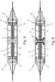
- the figure 5 of the present description presents the general structure of such a transducer, the structural and operating details of which are not repeated in the present description.
- the general principle of operation of such an electro-optical transducer consists in that the modulation of the wavelength of the laser wave produced is obtained by varying the length of the optical fiber element 12 constituting the cavity of the laser emission source, said optical fiber element being kept taut (mechanical pre-tension) by retaining elements 13 and 14 when it is at rest at a given ambient temperature ⁇ .
- the variation in length of the optical fiber element 12 is itself obtained by means of a piezoelectric actuator 18 arranged so as to act on the mechanical tension applied to the optical fiber element 12 as a function of the electrical voltage which is applied to it, electrical voltage coming, in this case from the electro-acoustic sensor with which it is associated.
- the variation in the mechanical tension thus applied to the fiber causes in a known manner a variation in its length L and thereby a variation in the length of the light wave produced.
- the piezoelectric actuator 18 consists of four bars of piezoelectric material arranged around the optical fiber element 12, each bar being fixed by one end to one of the holding elements 13 or 14 and by its other end to a support element 16 placed in a central position.
- the assembly is placed in a case consisting of a cylindrical body 51 closed by two end elements 52, the support element 16 being integral with the cylindrical body 51.
- such a transducer has the main advantages of its simplicity of structure, its compactness and its ease of use. Indeed, by changing length under the action of an electrical voltage, the piezoelectric actuator 18 acts directly on the mechanical tension applied to the segment of optical fiber 12.
- this type of transducer can easily be connected in series on an optical fiber link conveying the light signals produced in multiplexed form. by a plurality of sensors.
- This type of transducer has the drawback of being sensitive to variations in ambient temperature. Indeed, under the effect of temperature variations, an optical fiber sees its optical index vary and to a lesser extent its length.
- the wavelength of the fiber laser varies under the combined effect of the variation of the optical index ⁇ of the fiber segment 12 which constitutes it and of the length of this same segment.
- These variations themselves lead to a variation in the nominal wavelength ⁇ 0 , which has the disadvantageous effect of unnecessarily widening the range of wavelengths likely to be occupied by the signal produced by a transducer.
- electro-optical transducers comprising a laser source consisting of a fiber laser, for example a transducer of the type of that described in the patent application cited above, has the consequence of limiting the number of transducers which can be connected in series to the same optical fiber without risk of degradation of the signals transmitted due to temperature variations.
- a document WO 2017/102767 A1 discloses an electro-optical transducer.
- An object of the invention is to propose a solution making it possible to solve the problem explained above, that is to say consisting in proposing a means for making an electro-optical transducer insensitive to variations in ambient temperature a wavelength modulated fiber laser; in particular a transducer of the type described above and one embodiment of which is illustrated by figure 5 .
- the object of the invention is a device for compensating for the variations in temperature of the length.
- an optical fiber of an electro-optical transducer according to claim 1 comprising a tubular support element whose axis of symmetry coincides with the axis of said optical fiber and two terminal elements arranged axially with respect to the element support and each comprising a wall closing off the support element and delimiting inside the latter a cavity of length ⁇ L.
- At least one of the terminal elements, or first terminal element is configured to form a movable wall inside the support element, said element having a body of cylindrical shape, configured to be able to be inserted from the inside. 'inside the tubular support and to be able to slide axially inside the latter; said cylindrical body comprising an end wall.
- the tubular support and the end element are arranged and fixed to each other at one end of the support element such that the body of the end element is kept free to slide inside support.
- the sliding of the body of the first terminal element causing the axial displacement of its end wall inside the support element (23) and a variation in the length ⁇ L of said cavity.
- the materials respectively constituting the support element and the terminal element being chosen for their respective thermal expansion coefficients, such that the direction of variations in the length ⁇ L of said cavity as a function of the ambient temperature ⁇ is of opposite sign to direction of variation of said ambient temperature.
- the device thus behaves from the point of view of the closure walls, like an element with a negative thermal expansion coefficient.
- the temperature compensation device according to the invention can have different additional characteristics, in particular those mentioned below.
- said at least one terminal element comprises a cylindrical body, the open end of which has a flanged edge forming a flange which comes to bear on the end edge of the support element when the terminal element is inserted in. this last; said flange being fixed to the end edge of the support member.
- the material constituting the support element is a material having a coefficient of thermal expansion substantially lower than the coefficient of thermal expansion of the material constituting the first terminal element.
- the device comprises two terminal elements of identical structures, placed at each of the ends of the support element and forming two movable walls, each end element being inserted into the support by one of the ends of the support; the lengths of the bodies of the terminal elements being determined such that the length ⁇ L of the cavity delimited by the end walls is never zero whatever the value of the ambient temperature ⁇ .
- the outer faces of the end walls of the terminal elements of the device are configured to serve as interfaces with the mechanical structure for which the device is intended to provide temperature compensation.
- the device comprises a first terminal element placed at one of the ends of the support element and comprising an end wall forming a movable wall closing off one of the ends of the support element, said end element being inserted into the support by one of the ends of the support; as well as a second terminal element forming a fixed wall closing off the other end of the support element.
- the end wall of the first terminal element and the fixed wall form the second terminal element define the cavity of length ⁇ L.
- the length 1 of the body of the first terminal element is determined such that the length ⁇ L of the cavity delimited by the end wall of the latter and the fixed partition is never zero whatever the value of the ambient temperature ⁇ .
- Another subject of the invention is an electro-optical transducer comprising a laser source constituted by a segment of optical fiber, forming the laser cavity, fixed at each of its ends to a holding element.
- said retaining elements are kept apart from one another by a distance d by a piezoelectric actuator placed between them and bearing on the latter.
- the piezoelectric actuator is configured in such a way that its length varies as a function of the electric voltage which is applied to it, the variation in length inducing a substantially identical variation in the distance d separating the holding elements.
- the piezoelectric actuator comprises a plurality of bars of piezoelectric material, arranged longitudinally around the segment of optical fiber between the holding elements, as well as a temperature compensation device according to the invention, said device being arranged in the extension of the bars. of the piezoelectric actuator so that the length of the actuator is equal to the sum of the length of the bars of piezoelectric material and the distance ⁇ L which separates the end walls of the terminal elements of the device closing off the support element.
- the electro-optical transducer according to the invention can have different additional characteristics, in particular those mentioned below.
- the length of the piezoelectric actuator is defined such that when the latter is not excited by any electrical voltage, the distance d separating the holding elements induces a mechanical pre-tension on the segment of fiber said pre voltage allowing the actuator to vary the length of the fiber segment, in addition and in less around a nominal length value corresponding for the laser source to an emitted wavelength ⁇ 0 .
- the temperature compensation device comprising two identical terminal elements of cylindrical shape, each comprising an end wall
- the actuator piezoelectric comprises a plurality of bars of piezoelectric material arranged on either side of the temperature compensation device.
- Each of the bars is mechanically connected to one of the retaining elements by one of its ends and to the end wall of one of the terminal elements of said device by its other end.
- the respective lengths of the bars placed on either side of said device are substantially identical, so that the latter occupies a middle position in the structure of the actuator.
- the temperature compensation device comprising an end element forming a movable wall closing off one end of the support element and an end element forming a fixed wall closing off the other end of the support element
- the piezoelectric actuator comprises a plurality of bars of piezoelectric material, arranged so that all the bars are mechanically connected to the same retaining element by one of their ends and to the end wall of the terminal element forming said closure wall mobile by its other end.
- Said device is connected by the fixed closure wall to the other retaining element, so that the latter occupies an extreme position in the structure of the actuator.
- the respective lengths L of the support and 1 of the body of an end element constituting the temperature compensation device are defined such that, taking into account the temperature expansion coefficients of the materials constituting the support respectively and the end element, the variation in the length ⁇ L of the internal cavity of the temperature compensation device, induced by the variation in the ambient temperature ⁇ , is equal, in modulus, to the variation in the length of the fiber segment optics necessary to compensate for the variation in wavelength length emitted by the laser source induced by this variation in temperature.
- the figure 1 schematically presents the functional structure of an electro-optical transducer 11 taken as an example, for which the device according to the invention is in particular intended.
- Such a transducer 11 mainly comprises a laser emission source constituted by a fiber laser and modulation means formed by a piezoelectric actuator configured to induce a variation in the wavelength emitted by the laser source when it is excited by an electric voltage.
- the fiber laser comprises an optical fiber segment 12 forming a resonant cavity, a Bragg grating fiber for example, the fiber segment 12 being fixed by its two ends to holding elements 13 and 14 intended to transmit to the segment of fiber 12 a longitudinal mechanical tension induced by a piezoelectric actuator, the mechanical tension applied to the fiber segment being a function of the distance d separating the two elements 13 and 14.
- the piezoelectric actuator consists of bars 15 of monocrystalline piezoelectric material, arranged longitudinally, in other words in a direction parallel to the axis of the optical fiber segment, between the two holding elements 13 and 14, dimensioned and arranged so as to keep the two retaining elements 13 and 14 spaced from one another by a distance d, the value of which depends on the electric voltage which is applied to these bars.
- the bars 15 are moreover dimensioned in such a way that when no electric voltage is applied to them, they keep the two retaining elements 13 and 14 spaced from each other by a distance d 0 such that the segment of optical fiber constituting the laser undergoes a mechanical pre-tension of a given value.
- the pre-tension imposed on the optical fiber segment 12 for example induces the production of a laser wave of wavelength ⁇ 0 .
- the bars 15 of piezoelectric material can be arranged in different ways, as long as the arrangement considered makes it possible to control the mechanical tension applied to the optical fiber segment 12 by varying the electrical voltage applied to the bars. .
- the intermediate element 16 also has at its center an opening 17 allowing the optical fiber segment 12 to pass through it freely.
- the distance d between the two retaining elements 13 and 14 is controlled by the device consisting of the two groups of bars 15 and the intermediate element 16. At rest, when no electrical voltage is applied to the bars, the difference d is substantially equal to the sum of the lengths of each group of bars 15 and the thickness ⁇ L of the intermediate element 16.
- the electro-optical transducer 11, illustrated by figure 1 behaves in such a way that an electric voltage applied to the bars 15 constituting the piezoelectric actuator causes a modification of the length of the latter which modifies the value d of the spacing between the holding elements 13 and 14.
- the modification of this spacing causes a variation in length of the optical fiber segment 12 and consequently a variation in the mechanical tension applied to this segment 12.
- This variation in the mechanical tension applied to the optical fiber segment 12 ultimately results in a variation in the wavelength ⁇ emitted by the laser source.
- the electrical voltage applied to the actuator it is possible to vary the wavelength ⁇ of the laser source more or less around a nominal value ⁇ 0 , which corresponds to the applied mechanical voltage. to the fiber segment 12 when no electrical voltage is applied to the bars 15 of the actuator (pre-tension).
- the pre-tension imposed on the fiber thus advantageously makes it possible to modulate the value of the emitted wavelength ⁇ around the value ⁇ 0 by applying a positive or negative electric voltage to the bars 15 of the piezoelectric actuator.
- the variation in the wavelength ⁇ of the wave emitted by the fiber laser depends not only on the variation in length of the fiber segment 12, but also on the variation in the optical index ⁇ of the fiber used.
- variations are naturally induced by variations in temperature.
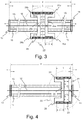
- the figures 2 and 3 present a simplified representation in longitudinal section of an electro-optical transducer 21, of the type illustrated by figure 1 , integrating the temperature compensation device 22 according to the invention.
- This simplified view only shows the elements of the transducer directly involved in the function of generating a modulated light wave.
- the means for applying an electric control voltage to the piezoelectric actuator are in particular not shown.
- the variation in the ambient temperature ⁇ induces a variation of the same sign of the optical index ⁇ of the fiber which itself induces a variation of the same sign in the value of the wavelength.
- the variation in the ambient temperature ⁇ induces a variation of the same sign in the length of the fiber which itself induces a variation of the same sign in the value of the wavelength.
- the solution implemented by the invention consists in using an additional means making it possible to induce a variation in length of the segment of fiber 12 in the opposite direction to the variation of index induced by the variation in ambient temperature ⁇ , and of sufficient amplitude to induce a variation in wavelength equal in modulus, except for the coefficient of proportionality k, to the variation in the optical index.
- the means used is moreover arranged at the level of the transducer such that the value of the distance d separating the retaining elements 13 and 14 of the segment of optical fiber 12 constituting the laser source, in other words the length of the fiber segment 12, or a function of a dimension of the means, of its thickness for example.
- the additional means used are arranged so as to intervene in the value of the difference d.
- the device 22 is placed in a central position instead of the intermediate element 16 of the figure 1 and comprises a support 23 and two terminal elements 24a and 24b placed at the two ends of the support 23.
- the support 23 of the device 22 presents, as illustrated by the sectional view of the figure 3 , the shape of a tube of length L open at its ends, preferably in the shape of a cylinder of revolution, having an axis of revolution substantially coincident with the axis of the optical fiber segment 12, the side wall of which defines an internal axial opening.
- each terminal element 24a or 24b is for its part configured to form a plug intended to partially close off one end of the support 23 of the device.
- Each terminal element 24a or 24b also has the shape of a tube, of length 1 less than half of the length L of the support 23. This tube is partially closed off at one of its ends by an end wall, 25a or 25b, or bottom wall, having an opening central circular allowing the optical fiber segment 12 of the laser source to pass freely through the device 22, when the latter is in place, while the other end is open.
- a terminal element 24 (24a or 24b) are defined such that the ends of the bars of piezoelectric material belonging to the same group can penetrate inside the terminal element and rest on the surface d 'a bottom wall 25 of said element.
- a terminal element 24 preferably has a substantially constant internal diameter.
- the respective shapes and dimensions of the support 23 and of the end elements 24a and 24b are further defined in such a way that the end element 24 in question can be inserted by its closed end inside the support 23, and pushed into it. inside the holder until the edge limiting its open end coincides with the edge of the opening of the holder 23 through which it entered.
- each terminal element 24 is configured so as to be able to be fixed to the support 23 at its open end.
- the open end of a terminal element 24 (24a or 24b) has a circumferential edge 26 (26a or 26b), or flanged edge, also making it possible to secure the end of the terminal element to the support 23 .
- each terminal element 24 is configured to be inserted inside the support 23 by its end closed by its end wall 25, and to be pressed into the support by sliding along the internal wall of this. last until the flanged edge 26 comes into abutment on the edge delimiting the opening of the support 23 through which it has been inserted into the latter.
- the device 22 therefore has, in the form of implementation considered, a tubular central part of length L which corresponds to the support 23, closed at each of its ends by a plug of also tubular shape.
- length 1 which corresponds to a terminal element 24a or 24b, this terminal element being closed at one of its ends by a bottom wall 25.
- Said stopper extends over its entire length 1 inside the central part.
- the end walls 25a and 25b of the terminal elements 24a and 24b then define an interior cavity 17 of given length ⁇ L equal to L-21.
- the piezoelectric actuator is formed by the bars 15 and by the device 22.
- Each of the bars is mechanically connected to one of the holding elements 13 and 14. by one of its ends and to the closure wall of one of the terminal elements 24a and 24b of said device 22 by its other end.
- the respective lengths of the bars 15 placed on either side of said device 22 are substantially identical, so that the latter occupies a substantially central position in the structure of the actuator 18.
- the length of the actuator thus formed, and consequently the length of the gap d separating the retaining elements 13 and 14, is then equal to the sum of the lengths of the bars 15 located on either side of the device and of the length ⁇ L of the cavity 17.
- each of the terminal elements 24 is fixed by its end to the support 23, at one of the end edges of the latter.
- An integral assembly is thus obtained for which the relative movements of the two end elements 24a and 24b with respect to the support element 23 are limited to the axial sliding of the body of each end element 24 along the internal wall of the support 23. , as illustrated by figure 3 .
- axial sliding is meant relative displacement of the outer surface of the body of the terminal element 24 considered relative to the inner wall of the support in a direction parallel to the axis of the fiber segment.
- This particular structure gives the device according to the invention a characteristic temperature behavior which is advantageously taken advantage of in the context of the invention.
- the end walls (bottom walls) 25a and 25b sink further inside the support 23, so that the length ⁇ L of the internal cavity 17 decreases, or conversely approach the ends of the latter so that the length ⁇ L of the interior cavity 17 increases.
- the two end elements 24a and 24b being mechanically linked to one another by the support 23, if the distance ⁇ L which separates the two walls 25a and 25b is considered, it is observed that, if the temperature ambient ⁇ increases, the walls 25a and 25b are approaching each other, as indicated by the arrows in solid lines on the figure 3 , so that two elements each resting on one of the walls come closer.
- the device 22 according to the invention advantageously behaves like an element having a negative thermal expansion coefficient which causes the length of the actuator to vary in a manner opposite to the temperature variation.
- the bars 15 having a low thermal expansion coefficient, the difference d between the two retaining elements 13 and 14 varies so that, when the ambient temperature ⁇ increases, the distance d decreases which has the effect of decrease the mechanical tension on the optical fiber segment 12.
- the decrease in mechanical tension has the effect of, for its part, to reduce the value of the nominal wavelength ⁇ 0 produced by the laser source, this reduction making it possible to compensate for the increase induced by the variation in the optical index of the fiber segment 12.
- the distance d increases which has the effect of increasing the mechanical tension on the optical fiber segment 12.
- the increase in the mechanical tension has the effect of increasing the value of the nominal wavelength ⁇ 0 produced by the laser source, this increase making it possible to compensate for the reduction induced by the variation in the optical index of the fiber segment 12.
- the respective lengths L and 1 of the support element 23 and of the terminal elements 24a and 24b are defined so as to obtain a variation in the length ⁇ L of the internal cavity 17 making it possible to achieve the compensation in desired temperature.
- the lengths L and 1 are determined in such a way that, taking into account the respective expansion coefficients of the materials constituting these elements, the length ⁇ L of the interior cavity 17 is never zero, whatever the value of the ambient temperature ⁇ .
- L and 1 are moreover defined in such a way that the variation in the length ⁇ L of the internal cavity 17 as a function of the ambient temperature ⁇ is substantially equal in modulus to the variation in length to be imposed on the optical fiber segment 12 constituting the source laser of the transducer 21 to vary the mechanical tension applied to the fiber so as to cancel the effects of the variations in the optical index of the fiber, induced by the variations in temperature, on the nominal value ⁇ 0 of the emitted wavelength .
- the different dimensional characteristics defining the compensation device according to the invention can be calculated analytically, knowing the dimensional characteristics of the transducer in which it is placed, from the thermal expansion coefficients of the materials used to make the support 23 and the end elements 24 and the law of variation of the index of the optical fiber constituting the segment 12.
- the compensation device 22 according to the invention can thus be defined as an element which is advantageously integrated into the structure of the piezoelectric actuator of the transducer 21 considered.
- the compensation device advantageously makes it possible to introduce into the structure of the piezoelectric actuator an element having a negative thermal expansion coefficient necessary to vary the length of the actuator so as to compensate variations in wavelength induced by variations in ambient temperature ⁇ .
- the considered transducer exhibits an axial symmetry (ie a symmetry with respect to a plane of transverse section passing through the center of the segment of fiber 12) sought after for particular functional reasons. not detailed here.
- the device according to the invention naturally takes the place of the original central element 16 illustrated in figure 1 and is structured to maintain the desired axial symmetry.
- it then has a symmetrical structure, with a tubular central support 23 and two identical terminal elements 24a and 24b, and is placed in the middle position inside the transducer.
- the figure 4 illustrates a variant implementation of the device according to the invention in the context of an electro-optical transducer 31 operating on the same principle as the transducer 11 considered previously, but not having the character of axial symmetry.
- the transducer considered here has a simplified structure, without an intermediate element, in which the piezoelectric actuator comprises bars 15 extending without interruption between the two retaining elements 13 and 14.
- the installation of the device 22 according to the invention can be carried out, as illustrated by figure 4 , at one of the ends of the actuator by placing the device according to the invention 22 in contact with one of the holding elements 13 or 14.
- the device according to the invention 22 then has a simplified form comprising for example a support element 23 closed at one of its ends by an end element formed by a fixed wall 41 and an end element 24 similar to the elements 24a and 24b described above.
- the fixed wall 41 and the end wall 25 of the terminal element 24 together form a cavity 17, the width of which varies as a function of the ambient temperature ⁇ in a manner analogous to the way in which the length of the cavity defined by the bottom walls 25a and 25b described above.
- a device 22 having a negative thermal expansion coefficient is obtained.
- the variation in the length of the cavity 17 is here induced by the only axial movement of the end wall 25 of the terminal element 24.
- the piezoelectric actuator here comprises a plurality of bars 15 made of piezoelectric material, arranged so that all the bars are mechanically connected to the same retaining element 13 by one of their ends and that each bar is connected to the wall of end 25 of the terminal element 24 of the device 22 by its other end.
- the device 22 is connected by its fixed wall 41 to the other retaining element 14, so that the latter occupies an extreme position in the structure of the actuator.
- the figures 5 and 6 respectively illustrate a view in axial section of an electro-optical transducer known from the state of the art, the structure and operating principle of which are described, as indicated above in the French patent application filed by the applicant and published under reference FR 3045817 , and a view in longitudinal section along the axis of the optical fiber segment 12, of the same transducer equipped with the compensation device according to the invention, in a central position corresponding to the first implementation example described in the present description.
- the installation of the temperature compensation device according to the invention in such a transducer can advantageously be carried out while retaining the original axial symmetry.
- it is simply necessary to implement a compensation device of symmetrical structure comprising in particular two terminal elements 24.
Landscapes
- Physics & Mathematics (AREA)
- Electromagnetism (AREA)
- Engineering & Computer Science (AREA)
- Optics & Photonics (AREA)
- Plasma & Fusion (AREA)
- General Physics & Mathematics (AREA)
- Life Sciences & Earth Sciences (AREA)
- Remote Sensing (AREA)
- Geology (AREA)
- General Life Sciences & Earth Sciences (AREA)
- Environmental & Geological Engineering (AREA)
- Geophysics (AREA)
- Acoustics & Sound (AREA)
- Mechanical Light Control Or Optical Switches (AREA)
- Optical Couplings Of Light Guides (AREA)
- Light Guides In General And Applications Therefor (AREA)
Claims (12)
- Vorrichtung (22) zum Kompensieren von Temperaturschwankungen der Länge einer optischen Faser (12) eines elektrooptischen Wandlers (11), mit einem rohrförmigen Trägerelement (23), dessen Symmetrieachse mit der Achse der optischen Faser (12) zusammenfällt, und zwei Endelementen, die axial in Bezug auf das Trägerelement (23) angeordnet sind und zwei Wände bilden, die das Trägerelement verschließen, um im Inneren des Trägers (23) einen Hohlraum (17) der Länge ΔL zu begrenzen; dadurch gekennzeichnet, dass mindestens ein erstes Endelement (24) zum Bilden einer beweglichen Wand im Inneren des Trägerelements (23) konfiguriert ist, wobei das Element (24) einen Körper von zylindrischer Form aufweist, der so konfiguriert ist, dass er in das Innere des rohrförmigen Trägers (23) eingesetzt werden kann und innerhalb des Letzteren axial gleiten kann; wobei der zylindrische Körper eine Endwand (25) aufweist, wobei der rohrförmige Träger (23) und das Endelement (24) am Endrand des Trägerelements (23) angeordnet und aneinander befestigt sind, so dass der Körper des Endelements (24) so gehalten wird, dass er innerhalb des Trägers (23) frei gleiten kann; wobei das Gleiten des Körpers des ersten Endelements (24) die axiale Verschiebung seiner Endwand (25) im Inneren des Trägerelements (23) und eine Variation der Länge ΔL des Hohlraums (17) bewirkt; wobei die das Trägerelement (23) bzw. das Endelement (24) bildenden Materialien für ihre jeweiligen Wärmeausdehnungskoeffizienten gewählt sind, so dass die Richtung der Variation der Länge ΔL des Hohlraums (17) in Abhängigkeit von der Umgebungstemperatur θ ein entgegengesetztes Vorzeichen zur Richtung der Variation der Umgebungstemperatur hat.
- Kompensationsvorrichtung nach Anspruch 1, dadurch gekennzeichnet, dass das eine bewegliche Wand bildende erste Endelement (24) einen zylindrischen Körper umfasst, dessen offenes Ende eine Bördelung (26) aufweist, wobei die Bördelung am Endrand des Trägers (23) anliegt, wenn das Endelement (24) in den Träger (23) eingesetzt ist; wobei der Rand am Endrand des Trägerelements befestigt ist.
- Temperaturkompensationsvorrichtung nach Anspruch 1 oder 2, dadurch gekennzeichnet, dass das das Trägerelement (23) bildende Material ein Material mit einem Wärmeausdehnungskoeffizienten ist, der wesentlich niedriger ist als der Wärmeausdehnungskoeffizient des das erste Endelement (24) bildenden Materials.
- Temperaturkompensationsvorrichtung nach einem der Ansprüche 1 bis 3, dadurch gekennzeichnet, dass:- der Träger (23) aus einem Material mit einem niedrigen Wärmeausdehnungskoeffizienten, insbesondere aus Glas, Quarz oder Zerodur, gefertigt ist, und- das erste Endelement (24) aus einem Material mit einem höheren Wärmeausdehnungskoeffizienten, insbesondere aus Polymermaterial, gefertigt ist.
- Temperaturkompensationsvorrichtung nach einem der Ansprüche 1 bis 4, dadurch gekennzeichnet, dass sie zwei Endelemente (24a, 24b) mit identischer Struktur umfasst, die an jedem der Enden des Trägerelements (23) platziert sind und zwei bewegliche Wände bilden, wobei jedes Endelement durch eines der Enden des Trägers in den Träger (23) eingesetzt ist; wobei die Längen der Körper der Endelemente (24a, 24b) so bestimmt werden, dass die Länge ΔL des von den Endwänden (25a, 25b) begrenzten Hohlraums (17) unabhängig vom Wert der Umgebungstemperatur θ niemals Null ist.
- Temperaturkompensationsvorrichtung nach Anspruch 5, dadurch gekennzeichnet, dass die Außenflächen der Endwände (25a, 25b) der Endelemente (24a, 24b) der Vorrichtung so konfiguriert sind, dass sie mit der mechanischen Struktur, für die die Vorrichtung (22) zur Temperaturkompensation vorgesehen ist, eine Schnittstelle bilden.
- Temperaturkompensationsvorrichtung nach einem der Ansprüche 1 bis 4, dadurch gekennzeichnet, dass sie ein erstes Endelement (24), das an einem der Enden des Trägerelements (23) platziert ist, und eine Endwand (25) aufweist, die eine bewegliche Wand bildet, die eines der Enden des Trägerelements (23) verschließt, wobei das Endelement durch eines der Enden des Trägers in den Träger (23) eingeführt ist; sowie ein zweites Endelement (41), das eine feste Wand bildet, die das andere Ende des Trägerelements verschließt; wobei die Endwand (25) des ersten Endelements (24) und die das zweite Endelement (41) bildende feste Wand den Hohlraum (17) der Länge ΔL definieren; wobei die Länge 1 des Körpers des ersten Endelements (24) so festgelegt ist, dass die Länge ΔL des Hohlraums (17), der durch dessen Endwand (25) und die feste Trennwand (41) begrenzt ist, unabhängig vom Wert der Umgebungstemperatur θ niemals Null ist.
- Elektrooptischer Wandler mit einer Laserquelle, die aus einem optischen Fasersegment (12) besteht, das an jedem seiner Enden an einem Halteelement (13, 14) befestigt ist; wobei die Halteelemente durch einen piezoelektrischen Aktuator (18), der zwischen ihnen angeordnet ist und daran anliegt, um einen Abstand d voneinander entfernt gehalten werden; wobei der Aktuator (18) so konfiguiert ist, dass seine Länge in Abhängigkeit von der daran angelegten elektrischen Spannung variiert, wobei die Längenvariation eine im Wesentlichen identische Variation des Abstands d zwischen den Halteelementen (13, 14) bewirkt; wobei der Wandler dadurch gekennzeichnet ist, dass der Aktuator (18) eine Mehrzahl von Stäben (15) aus piezoelektrischem Material, die in Längsrichtung um das optische Fasersegment (12) zwischen den Halteelementen (13, 14) angeordnet sind, sowie eine Temperaturkompensationsvorrichtung (22) nach einem der Ansprüche 1 bis 7 umfasst, wobei die Vorrichtung in der Verlängerung der Stäbe (15) des Aktuators so angeordnet ist, dass die Länge des Aktuators im Wesentlichen gleich der Summe aus der Länge der Stäbe (15) aus piezoelektrischem Material und dem Spalt ΔL zwischen den Verschlusswänden (24a, 24b) der Vorrichtung ist.
- Elektrooptischer Wandler nach Anspruch 8, dadurch gekennzeichnet, dass die Länge des piezoelektrischen Aktuators so definiert ist, dass, wenn dieser nicht durch eine elektrische Spannung angeregt ist, der Abstand d zwischen den Halteelementen (13, 14) eine mechanische Vorspannung auf das Fasersegment (12) induziert, wobei die Vorspannung es zulässt, dass der Aktuator (18) die Länge des Fasersegments (12) positiv oder negativ um einen Nennlängenwert variiert, der für die Laserquelle einer emittierten Wellenlänge λ0 entspricht.
- Elektrooptischer Wandler nach Anspruch 8 oder 9, dadurch gekennzeichnet, dass der piezoelektrische Aktuator (18) eine Mehrzahl von auf beiden Seiten der Temperaturkompensationsvorrichtung (22) angeordneten Stäben (15) aus piezoelektrischem Material umfasst, wobei jeder der Stäbe an einem seiner Enden mechanisch mit einem der Halteelemente (13, 14) und an seinem anderen Ende mit einer der Verschlusswände der Vorrichtung (22) verbunden ist, wobei die jeweiligen Längen der auf beiden Seiten der Vorrichtung (22) platzierten Stäbe (15) im Wesentlichen identisch sind, so dass Letztere (22) eine mittlere Position in der Aktuatorstruktur (18) einnimmt.
- Elektrooptischer Wandler nach Anspruch 8 oder 9, dadurch gekennzeichnet, dass der piezoelektrische Aktuator (18) eine Mehrzahl von Stäben (15) aus piezoelektrischem Material umfasst, die so angeordnet sind, dass alle Stäbe an einem ihrer Enden mechanisch mit demselben Halteelement (13) verbunden sind und jeder Stab an seinem anderen Ende mit der Verschlusswand (25) des ersten Endelements (24) der Temperaturkompensationsvorrichtung (22) verbunden ist, wobei die Vorrichtung (22) durch ihre feste Wand (41) mit dem anderen Halteelement (14) verbunden ist, so dass Letztere (22) eine Endposition in der Struktur des Aktuators (18) einnimmt.
- Elektrooptischer Wandler nach einem der Ansprüche 8 bis 11, dadurch gekennzeichnet, dass die jeweiligen Längen L des Trägers (23) und 1 des Körpers eines die Temperaturkompensationsvorrichtung (22) bildenden Anschlußelements (24) so definiert sind, dass unter Berücksichtigung der Temperaturausdehnungskoeffizienten der den Träger (23) bzw. das Anschlußelement (24) bildenden Materialien die durch die Änderung der Umgebungstemperatur 0 induzierte Variation der Länge ΔL des inneren Hohlraums der Temperaturkompensationsvorrichtung (22) im Modul gleich der Variation der Länge des optischen Fasersegments (12) ist, die notwendig ist, um die durch diese Temperaturänderung induzierte Variation der von der Laserquelle emittierten Wellenlänge zu kompensieren.
Applications Claiming Priority (2)
| Application Number | Priority Date | Filing Date | Title |
|---|---|---|---|
| FR1700797A FR3069661A1 (fr) | 2017-07-27 | 2017-07-27 | Dispositif de compensation en temperature et transpondeur electro-optique mettant en oeuvre un tel dispositif |
| PCT/EP2018/069999 WO2019020604A2 (fr) | 2017-07-27 | 2018-07-24 | Dispositif de compensation en temperature et transpondeur electro-optique mettant en œuvre un tel dispositif |
Publications (2)
| Publication Number | Publication Date |
|---|---|
| EP3658869A2 EP3658869A2 (de) | 2020-06-03 |
| EP3658869B1 true EP3658869B1 (de) | 2021-05-26 |
Family
ID=61132446
Family Applications (1)
| Application Number | Title | Priority Date | Filing Date |
|---|---|---|---|
| EP18740871.1A Active EP3658869B1 (de) | 2017-07-27 | 2018-07-24 | Temperaturkompensationsvorrichtung und elektrooptischer wandler mit einer solchen vorrichtung |
Country Status (6)
| Country | Link |
|---|---|
| US (1) | US10992099B1 (de) |
| EP (1) | EP3658869B1 (de) |
| AU (1) | AU2018308894B2 (de) |
| CA (1) | CA3071203A1 (de) |
| FR (1) | FR3069661A1 (de) |
| WO (1) | WO2019020604A2 (de) |
Families Citing this family (4)
| Publication number | Priority date | Publication date | Assignee | Title |
|---|---|---|---|---|
| CN110007338A (zh) * | 2019-04-13 | 2019-07-12 | 胜利油田新胜石油物探技术服务有限责任公司 | 一种压电地震检波器信号调理电路 |
| CN110244348B (zh) * | 2019-06-06 | 2021-04-02 | 山东科技大学 | 一种光电复合式地震检波器及检测系统 |
| CN115220089B (zh) * | 2022-08-11 | 2025-10-17 | 西北大学 | 一种基于额外横向力加载的光纤光栅检波器 |
| CN115513762B (zh) * | 2022-09-26 | 2026-02-10 | 华南理工大学 | 具有压电促动功能的高重频激光谐振腔及脉冲锁定装置 |
Family Cites Families (8)
| Publication number | Priority date | Publication date | Assignee | Title |
|---|---|---|---|---|
| FR2795528B1 (fr) * | 1999-06-22 | 2002-07-26 | Highwave Optical Tech | Procede de stabilisation et d'accordabilite de la longueur d'onde de reseaux de bragg |
| JP2001041983A (ja) * | 1999-07-29 | 2001-02-16 | Matsushita Electric Ind Co Ltd | 光電圧センサ |
| US6584248B2 (en) * | 2001-10-09 | 2003-06-24 | Corning Incorporated | Temperature-compensated optical grating device |
| US20030081925A1 (en) * | 2001-11-01 | 2003-05-01 | Jacques Albert | Passive temperature compensating fixture for optical grating devices |
| US7570386B2 (en) * | 2005-09-15 | 2009-08-04 | Lexmark International, Inc. | Systems and methods that compensate for scan path errors in a multi-beam electrophotographic imaging apparatus |
| KR101016179B1 (ko) * | 2010-05-01 | 2011-02-24 | (주)엠이엘 | 브라그 격자 내장 광섬유 커넥터 |
| JP2017528925A (ja) * | 2014-09-22 | 2017-09-28 | イムラ アメリカ インコーポレイテッド | 低キャリア位相ノイズファイバ発振器 |
| FR3045817B1 (fr) * | 2015-12-16 | 2018-01-19 | Thales | Transducteur electro-optique |
-
2017
- 2017-07-27 FR FR1700797A patent/FR3069661A1/fr not_active Ceased
-
2018
- 2018-07-24 US US16/634,522 patent/US10992099B1/en active Active
- 2018-07-24 EP EP18740871.1A patent/EP3658869B1/de active Active
- 2018-07-24 WO PCT/EP2018/069999 patent/WO2019020604A2/fr not_active Ceased
- 2018-07-24 AU AU2018308894A patent/AU2018308894B2/en active Active
- 2018-07-24 CA CA3071203A patent/CA3071203A1/en active Pending
Also Published As
| Publication number | Publication date |
|---|---|
| WO2019020604A3 (fr) | 2019-06-06 |
| EP3658869A2 (de) | 2020-06-03 |
| WO2019020604A2 (fr) | 2019-01-31 |
| US20210119400A1 (en) | 2021-04-22 |
| AU2018308894A1 (en) | 2020-03-05 |
| CA3071203A1 (en) | 2019-01-31 |
| US10992099B1 (en) | 2021-04-27 |
| FR3069661A1 (fr) | 2019-02-01 |
| AU2018308894B2 (en) | 2023-11-09 |
Similar Documents
| Publication | Publication Date | Title |
|---|---|---|
| EP3658869B1 (de) | Temperaturkompensationsvorrichtung und elektrooptischer wandler mit einer solchen vorrichtung | |
| FR2974263A1 (fr) | Hydrophone tout optique insensible a la temperature et a la pression statique | |
| WO2002063256A2 (fr) | Dispositif optoelectronique a filtrage de longueur d'onde par couplage de cavites | |
| FR3041761A1 (fr) | Capteur physique opto-mecanique a sensibilite amelioree | |
| EP0033048A1 (de) | Interferometer mit abstimmbarer optischer Höhlung, das eine optische monomoden Faser befasst, und dessen Anwendung zur Filtrierung und Spektrographie | |
| EP2141520A1 (de) | Kupplungsvorrichtung mit kompensierter Doppelbrechung | |
| FR2626082A1 (fr) | Dispositif d'optique integree permettant de separer les composantes polarisees d'un champ electromagnetique guide et procede de realisation du dispositif | |
| EP3513230B1 (de) | Optische kupplungsvorrichtung | |
| EP4081770B1 (de) | Optische vorrichtung zur erfassung einer schallwelle | |
| EP3571513B1 (de) | Sonde für ein rasterkraftmikroskop mit einem optomechanischen resonator und rasterkraftmikroskop mit solch einer sonde | |
| EP1092167A1 (de) | Optisches filter mit gitter und apodisiertem spektralem verhalten | |
| EP1494293A2 (de) | Photodetektor mit vertikalem Resonanzhohlraum, Anordnung und entsprechedes Telekommunikationssystem | |
| EP3312616B1 (de) | Miniaturisierte sonde für rasterkraftmikroskopie mit geringem platzbedarf | |
| EP3200363B1 (de) | System zur linearen optischen abtastung und kohärenten erkennung eines optischen signals | |
| FR3046853A1 (fr) | Cavite optique couplee optiquement a un guide d'onde. | |
| CA2102593A1 (fr) | Dispositif de mesure d'une caracteristique d'un objet en optique integree, par interferometrie | |
| EP1546770B1 (de) | Optische filterkomponente mit flacher oberseite | |
| EP1291707A1 (de) | Optischer sättigbarer Absorber und dessen Verwendung zum Regenerieren eines Wellenmultiplexsignales | |
| EP1495351A1 (de) | Verfahren zur herstellung eines abstimmbaren optischen filters | |
| FR2795528A1 (fr) | Procede de stabilisation et d'accordabilite de la longueur d'onde de reseaux de bragg | |
| FR2862453A1 (fr) | Module de compensation de dispersion chromatique | |
| FR2929774A1 (fr) | Dispositif de resonance micro-electromecanique a structure periodique. | |
| FR2860077A1 (fr) | Filtre spatial de phase pour faisceau optique, systeme et procede correspondant | |
| WO2025109281A1 (fr) | Procede et dispositif de communication-bidirectionnelle sur une seule fibre optique avec une seule source de lumiere | |
| EP4671695A1 (de) | Verbessertes mems- oder nms-messsystem mit mehreren sensoren |
Legal Events
| Date | Code | Title | Description |
|---|---|---|---|
| STAA | Information on the status of an ep patent application or granted ep patent |
Free format text: STATUS: UNKNOWN |
|
| STAA | Information on the status of an ep patent application or granted ep patent |
Free format text: STATUS: THE INTERNATIONAL PUBLICATION HAS BEEN MADE |
|
| PUAI | Public reference made under article 153(3) epc to a published international application that has entered the european phase |
Free format text: ORIGINAL CODE: 0009012 |
|
| STAA | Information on the status of an ep patent application or granted ep patent |
Free format text: STATUS: REQUEST FOR EXAMINATION WAS MADE |
|
| 17P | Request for examination filed |
Effective date: 20200130 |
|
| AK | Designated contracting states |
Kind code of ref document: A2 Designated state(s): AL AT BE BG CH CY CZ DE DK EE ES FI FR GB GR HR HU IE IS IT LI LT LU LV MC MK MT NL NO PL PT RO RS SE SI SK SM TR |
|
| AX | Request for extension of the european patent |
Extension state: BA ME |
|
| DAV | Request for validation of the european patent (deleted) | ||
| DAX | Request for extension of the european patent (deleted) | ||
| GRAP | Despatch of communication of intention to grant a patent |
Free format text: ORIGINAL CODE: EPIDOSNIGR1 |
|
| STAA | Information on the status of an ep patent application or granted ep patent |
Free format text: STATUS: GRANT OF PATENT IS INTENDED |
|
| INTG | Intention to grant announced |
Effective date: 20210303 |
|
| GRAS | Grant fee paid |
Free format text: ORIGINAL CODE: EPIDOSNIGR3 |
|
| GRAA | (expected) grant |
Free format text: ORIGINAL CODE: 0009210 |
|
| STAA | Information on the status of an ep patent application or granted ep patent |
Free format text: STATUS: THE PATENT HAS BEEN GRANTED |
|
| AK | Designated contracting states |
Kind code of ref document: B1 Designated state(s): AL AT BE BG CH CY CZ DE DK EE ES FI FR GB GR HR HU IE IS IT LI LT LU LV MC MK MT NL NO PL PT RO RS SE SI SK SM TR |
|
| REG | Reference to a national code |
Ref country code: GB Ref legal event code: FG4D Free format text: NOT ENGLISH |
|
| REG | Reference to a national code |
Ref country code: CH Ref legal event code: EP |
|
| REG | Reference to a national code |
Ref country code: AT Ref legal event code: REF Ref document number: 1396693 Country of ref document: AT Kind code of ref document: T Effective date: 20210615 |
|
| REG | Reference to a national code |
Ref country code: DE Ref legal event code: R096 Ref document number: 602018017742 Country of ref document: DE |
|
| REG | Reference to a national code |
Ref country code: IE Ref legal event code: FG4D Free format text: LANGUAGE OF EP DOCUMENT: FRENCH |
|
| REG | Reference to a national code |
Ref country code: NL Ref legal event code: FP |
|
| REG | Reference to a national code |
Ref country code: LT Ref legal event code: MG9D |
|
| REG | Reference to a national code |
Ref country code: SE Ref legal event code: TRGR |
|
| REG | Reference to a national code |
Ref country code: AT Ref legal event code: MK05 Ref document number: 1396693 Country of ref document: AT Kind code of ref document: T Effective date: 20210526 |
|
| PG25 | Lapsed in a contracting state [announced via postgrant information from national office to epo] |
Ref country code: HR Free format text: LAPSE BECAUSE OF FAILURE TO SUBMIT A TRANSLATION OF THE DESCRIPTION OR TO PAY THE FEE WITHIN THE PRESCRIBED TIME-LIMIT Effective date: 20210526 Ref country code: LT Free format text: LAPSE BECAUSE OF FAILURE TO SUBMIT A TRANSLATION OF THE DESCRIPTION OR TO PAY THE FEE WITHIN THE PRESCRIBED TIME-LIMIT Effective date: 20210526 Ref country code: FI Free format text: LAPSE BECAUSE OF FAILURE TO SUBMIT A TRANSLATION OF THE DESCRIPTION OR TO PAY THE FEE WITHIN THE PRESCRIBED TIME-LIMIT Effective date: 20210526 Ref country code: BG Free format text: LAPSE BECAUSE OF FAILURE TO SUBMIT A TRANSLATION OF THE DESCRIPTION OR TO PAY THE FEE WITHIN THE PRESCRIBED TIME-LIMIT Effective date: 20210826 Ref country code: AT Free format text: LAPSE BECAUSE OF FAILURE TO SUBMIT A TRANSLATION OF THE DESCRIPTION OR TO PAY THE FEE WITHIN THE PRESCRIBED TIME-LIMIT Effective date: 20210526 |
|
| REG | Reference to a national code |
Ref country code: NO Ref legal event code: T2 Effective date: 20210526 |
|
| PG25 | Lapsed in a contracting state [announced via postgrant information from national office to epo] |
Ref country code: IS Free format text: LAPSE BECAUSE OF FAILURE TO SUBMIT A TRANSLATION OF THE DESCRIPTION OR TO PAY THE FEE WITHIN THE PRESCRIBED TIME-LIMIT Effective date: 20210926 Ref country code: GR Free format text: LAPSE BECAUSE OF FAILURE TO SUBMIT A TRANSLATION OF THE DESCRIPTION OR TO PAY THE FEE WITHIN THE PRESCRIBED TIME-LIMIT Effective date: 20210827 Ref country code: LV Free format text: LAPSE BECAUSE OF FAILURE TO SUBMIT A TRANSLATION OF THE DESCRIPTION OR TO PAY THE FEE WITHIN THE PRESCRIBED TIME-LIMIT Effective date: 20210526 Ref country code: PL Free format text: LAPSE BECAUSE OF FAILURE TO SUBMIT A TRANSLATION OF THE DESCRIPTION OR TO PAY THE FEE WITHIN THE PRESCRIBED TIME-LIMIT Effective date: 20210526 Ref country code: PT Free format text: LAPSE BECAUSE OF FAILURE TO SUBMIT A TRANSLATION OF THE DESCRIPTION OR TO PAY THE FEE WITHIN THE PRESCRIBED TIME-LIMIT Effective date: 20210927 Ref country code: RS Free format text: LAPSE BECAUSE OF FAILURE TO SUBMIT A TRANSLATION OF THE DESCRIPTION OR TO PAY THE FEE WITHIN THE PRESCRIBED TIME-LIMIT Effective date: 20210526 |
|
| PG25 | Lapsed in a contracting state [announced via postgrant information from national office to epo] |
Ref country code: SK Free format text: LAPSE BECAUSE OF FAILURE TO SUBMIT A TRANSLATION OF THE DESCRIPTION OR TO PAY THE FEE WITHIN THE PRESCRIBED TIME-LIMIT Effective date: 20210526 Ref country code: EE Free format text: LAPSE BECAUSE OF FAILURE TO SUBMIT A TRANSLATION OF THE DESCRIPTION OR TO PAY THE FEE WITHIN THE PRESCRIBED TIME-LIMIT Effective date: 20210526 Ref country code: ES Free format text: LAPSE BECAUSE OF FAILURE TO SUBMIT A TRANSLATION OF THE DESCRIPTION OR TO PAY THE FEE WITHIN THE PRESCRIBED TIME-LIMIT Effective date: 20210526 Ref country code: RO Free format text: LAPSE BECAUSE OF FAILURE TO SUBMIT A TRANSLATION OF THE DESCRIPTION OR TO PAY THE FEE WITHIN THE PRESCRIBED TIME-LIMIT Effective date: 20210526 Ref country code: SM Free format text: LAPSE BECAUSE OF FAILURE TO SUBMIT A TRANSLATION OF THE DESCRIPTION OR TO PAY THE FEE WITHIN THE PRESCRIBED TIME-LIMIT Effective date: 20210526 Ref country code: DK Free format text: LAPSE BECAUSE OF FAILURE TO SUBMIT A TRANSLATION OF THE DESCRIPTION OR TO PAY THE FEE WITHIN THE PRESCRIBED TIME-LIMIT Effective date: 20210526 Ref country code: CZ Free format text: LAPSE BECAUSE OF FAILURE TO SUBMIT A TRANSLATION OF THE DESCRIPTION OR TO PAY THE FEE WITHIN THE PRESCRIBED TIME-LIMIT Effective date: 20210526 |
|
| PGFP | Annual fee paid to national office [announced via postgrant information from national office to epo] |
Ref country code: SE Payment date: 20210712 Year of fee payment: 4 |
|
| REG | Reference to a national code |
Ref country code: CH Ref legal event code: PL |
|
| REG | Reference to a national code |
Ref country code: DE Ref legal event code: R097 Ref document number: 602018017742 Country of ref document: DE |
|
| PLBE | No opposition filed within time limit |
Free format text: ORIGINAL CODE: 0009261 |
|
| STAA | Information on the status of an ep patent application or granted ep patent |
Free format text: STATUS: NO OPPOSITION FILED WITHIN TIME LIMIT |
|
| PG25 | Lapsed in a contracting state [announced via postgrant information from national office to epo] |
Ref country code: MC Free format text: LAPSE BECAUSE OF FAILURE TO SUBMIT A TRANSLATION OF THE DESCRIPTION OR TO PAY THE FEE WITHIN THE PRESCRIBED TIME-LIMIT Effective date: 20210526 |
|
| REG | Reference to a national code |
Ref country code: BE Ref legal event code: MM Effective date: 20210731 |
|
| PG25 | Lapsed in a contracting state [announced via postgrant information from national office to epo] |
Ref country code: LI Free format text: LAPSE BECAUSE OF NON-PAYMENT OF DUE FEES Effective date: 20210731 Ref country code: CH Free format text: LAPSE BECAUSE OF NON-PAYMENT OF DUE FEES Effective date: 20210731 |
|
| 26N | No opposition filed |
Effective date: 20220301 |
|
| PG25 | Lapsed in a contracting state [announced via postgrant information from national office to epo] |
Ref country code: IS Free format text: LAPSE BECAUSE OF FAILURE TO SUBMIT A TRANSLATION OF THE DESCRIPTION OR TO PAY THE FEE WITHIN THE PRESCRIBED TIME-LIMIT Effective date: 20210926 Ref country code: LU Free format text: LAPSE BECAUSE OF NON-PAYMENT OF DUE FEES Effective date: 20210724 Ref country code: AL Free format text: LAPSE BECAUSE OF FAILURE TO SUBMIT A TRANSLATION OF THE DESCRIPTION OR TO PAY THE FEE WITHIN THE PRESCRIBED TIME-LIMIT Effective date: 20210526 |
|
| PG25 | Lapsed in a contracting state [announced via postgrant information from national office to epo] |
Ref country code: IT Free format text: LAPSE BECAUSE OF FAILURE TO SUBMIT A TRANSLATION OF THE DESCRIPTION OR TO PAY THE FEE WITHIN THE PRESCRIBED TIME-LIMIT Effective date: 20210526 Ref country code: IE Free format text: LAPSE BECAUSE OF NON-PAYMENT OF DUE FEES Effective date: 20210724 Ref country code: BE Free format text: LAPSE BECAUSE OF NON-PAYMENT OF DUE FEES Effective date: 20210731 |
|
| REG | Reference to a national code |
Ref country code: SE Ref legal event code: EUG |
|
| PG25 | Lapsed in a contracting state [announced via postgrant information from national office to epo] |
Ref country code: SE Free format text: LAPSE BECAUSE OF NON-PAYMENT OF DUE FEES Effective date: 20220725 |
|
| PG25 | Lapsed in a contracting state [announced via postgrant information from national office to epo] |
Ref country code: CY Free format text: LAPSE BECAUSE OF FAILURE TO SUBMIT A TRANSLATION OF THE DESCRIPTION OR TO PAY THE FEE WITHIN THE PRESCRIBED TIME-LIMIT Effective date: 20210526 |
|
| P01 | Opt-out of the competence of the unified patent court (upc) registered |
Effective date: 20230606 |
|
| PG25 | Lapsed in a contracting state [announced via postgrant information from national office to epo] |
Ref country code: HU Free format text: LAPSE BECAUSE OF FAILURE TO SUBMIT A TRANSLATION OF THE DESCRIPTION OR TO PAY THE FEE WITHIN THE PRESCRIBED TIME-LIMIT; INVALID AB INITIO Effective date: 20180724 |
|
| PGFP | Annual fee paid to national office [announced via postgrant information from national office to epo] |
Ref country code: NO Payment date: 20230712 Year of fee payment: 6 |
|
| PG25 | Lapsed in a contracting state [announced via postgrant information from national office to epo] |
Ref country code: MK Free format text: LAPSE BECAUSE OF FAILURE TO SUBMIT A TRANSLATION OF THE DESCRIPTION OR TO PAY THE FEE WITHIN THE PRESCRIBED TIME-LIMIT Effective date: 20210526 |
|
| PG25 | Lapsed in a contracting state [announced via postgrant information from national office to epo] |
Ref country code: MT Free format text: LAPSE BECAUSE OF FAILURE TO SUBMIT A TRANSLATION OF THE DESCRIPTION OR TO PAY THE FEE WITHIN THE PRESCRIBED TIME-LIMIT Effective date: 20210526 |
|
| PG25 | Lapsed in a contracting state [announced via postgrant information from national office to epo] |
Ref country code: NO Free format text: LAPSE BECAUSE OF NON-PAYMENT OF DUE FEES Effective date: 20240731 |
|
| PGFP | Annual fee paid to national office [announced via postgrant information from national office to epo] |
Ref country code: GB Payment date: 20250619 Year of fee payment: 8 |
|
| PGFP | Annual fee paid to national office [announced via postgrant information from national office to epo] |
Ref country code: NL Payment date: 20250627 Year of fee payment: 8 |
|
| PGFP | Annual fee paid to national office [announced via postgrant information from national office to epo] |
Ref country code: FR Payment date: 20250623 Year of fee payment: 8 |
|
| PGFP | Annual fee paid to national office [announced via postgrant information from national office to epo] |
Ref country code: DE Payment date: 20250618 Year of fee payment: 8 |
|
| PG25 | Lapsed in a contracting state [announced via postgrant information from national office to epo] |
Ref country code: TR Free format text: LAPSE BECAUSE OF FAILURE TO SUBMIT A TRANSLATION OF THE DESCRIPTION OR TO PAY THE FEE WITHIN THE PRESCRIBED TIME-LIMIT Effective date: 20210526 |