EP3658846B1 - Schusswaffenblockierer und verfahren zur handhabung davon - Google Patents
Schusswaffenblockierer und verfahren zur handhabung davon Download PDFInfo
- Publication number
- EP3658846B1 EP3658846B1 EP18752207.3A EP18752207A EP3658846B1 EP 3658846 B1 EP3658846 B1 EP 3658846B1 EP 18752207 A EP18752207 A EP 18752207A EP 3658846 B1 EP3658846 B1 EP 3658846B1
- Authority
- EP
- European Patent Office
- Prior art keywords
- firearm
- firearm obstructer
- obstructer
- arm
- passage
- Prior art date
- Legal status (The legal status is an assumption and is not a legal conclusion. Google has not performed a legal analysis and makes no representation as to the accuracy of the status listed.)
- Active
Links
Images


Classifications
-
- F—MECHANICAL ENGINEERING; LIGHTING; HEATING; WEAPONS; BLASTING
- F41—WEAPONS
- F41A—FUNCTIONAL FEATURES OR DETAILS COMMON TO BOTH SMALLARMS AND ORDNANCE, e.g. CANNONS; MOUNTINGS FOR SMALLARMS OR ORDNANCE
- F41A17/00—Safety arrangements, e.g. safeties
- F41A17/44—Safety plugs, e.g. for plugging-up cartridge chambers, barrels, magazine spaces
Definitions
- the present invention is directed towards a firearm obstructer and a method of operating the same.
- the present invention is directed towards a firearm obstructer suitable for use in obstructing a passage between a chamber and a muzzle of a firearm, and methods of operating the same.
- Firearm owners may secure their equipment in safes so that they cannot be accessed, including by storing firearms and ammunition separately. Firearm owners may use locking devices to lock the trigger of the firearm in place to prevent firearm discharge.
- the firearm obstructer comprises a base that cooperates with the firearm's extractor, a pliable and expandable portion attached to the base for expanding to create an interference fit with the firearm's bore, and a compression shaft that, when rotated, will force the expandable portion outwardly to create the interference fit.
- US6584718B1 discloses a firearm locking mechanism and US5699687A discloses a firearm security device.
- a firearm obstructer suitable for use in obstructing a passage between a chamber and a muzzle of a firearm
- the firearm obstructer comprises: an arm, and a body having a tapered region, wherein the arm is arranged to move relative to the tapered region to transition the firearm obstructer between locking and unlocking configurations, wherein in the locking configuration the firearm obstructer is arranged to engage with the passage to hold the firearm obstructer in place in the passage, and wherein the firearm obstructer so positioned provides an obstruction in the passage, and wherein in the unlocking configuration the firearm obstructer is removable from the passage; and further comprising a locking member, wherein the locking member is connected to the arm so as to cause the relative movement between the arm and the tapered region, and wherein rotation of the locking member causes relative movement of the arm and the tapered region, and wherein rotation of the locking member in one direction causes relative movement of the arm and the tapered region to transition
- firearm may refer to a firearm having a barrel with an internal bore that is 'rifled'/grooved or smooth.”
- the firearm obstructer of the first aspect may transition between locking and unlocking configurations by the movement of an arm relative to a tapered region of the firearm obstructer.
- the firearm obstructer therefore does not require a compression shaft for placing an expandable portion under compression, as required by the existing device disclosed in US Patent Number 5950344 .
- the firearm obstructer may have a first end portion and a second end portion.
- the axial direction may be from the first end portion to the second end portion and the radial direction may be perpendicular to the axial direction.
- the arm may be arranged to move relative to the tapered region, in the axial direction, to transition the firearm obstructer between the locking and unlocking configuration.
- the arm may be arranged to extend radially outward when transitioning from the unlocking to the locking configuration.
- the first end portion may be a wide portion and the second end portion may be a narrow portion of the firearm obstructer.
- the narrow portion may comprise the body and the arm. In use, the narrow portion may be inserted into the passage and the wide portion may be positioned outside of the passage. The wide portion may prevent the firearm obstructer from being inserted completely into the passage.
- the wide portion positioned outside of the passage may enable a firearm user to easily identify the presence of the firearm obstructer in the passage.
- the wide portion suitably prevents the firearm obstructer being accidentally dropped or positioned too far down the passage such that it cannot easily be retrieved.
- the wide portion may provide a convenient point to grasp the firearm obstructer such that it may be removed from the passage when in the unlocking configuration.
- the narrow portion may be inserted into a barrel of the firearm.
- the narrow portion may be inserted into the breech-end of the barrel of the firearm.
- the wide portion may be connected to the narrow portion by a frangible connection arranged to break in response to a predetermined amount of force being applied to the wide portion, and separate the wide portion from the narrow portion such that, in use, the narrow portion may remain within the passage.
- the wide portion may be a cap.
- the wide portion may be connected to the narrow portion by adhesive.
- the wide portion may separate from the narrow portion in the event that a predetermined amount of force is applied to the wide portion.
- a predetermined amount of force may for example be applied by an unauthorised person attempting to pull or pry the firearm obstructer out of the passage when the firearm obstructer is in the locking configuration.
- the wide portion is thus designed to break away from the narrow portion at the frangible connection such that the narrow portion may be left within the passage in the locking configuration, where it will be difficult to dislodge by the unauthorised person. Therefore, the frangible connection between the wide portion and the narrow portions provides a security measure for preventing unauthorised removal of the firearm obstructer.
- the firearm obstructer comprises a locking member, wherein rotation of the locking member may cause relative movement of the arm and the tapered region.
- the firearm obstructer is able to transition between unlocking and locking configurations by rotation of the locking member.
- Rotation of the locking member in one direction causes relative movement of the arm and the tapered region to transition the firearm obstructer to the locking configuration.
- Rotation of the locking member in an opposite direction allows the firearm obstructer to transition to the unlocking configuration.
- the locking member may cooperate with a key such that rotation of the key rotates the locking member.
- the locking member may cooperate with a key such that rotation of the locking member is only possible with the key.
- the locking member may comprise a threaded shaft.
- the body and the arm may have an internal aperture for receiving the threaded shaft.
- the locking member is connected to the arm so as to cause the relative movement between the arm and the tapered region.
- the connection between the locking member and the arm is arranged to break in response to a predetermined amount of force being applied to the connection so as to separate the locking member from the arm.
- the locking member may be connected to the arm by one or more shear pins.
- connection between the locking member and the arm is arranged to break in response to a predetermined amount of force, for example above a shearing threshold, being applied to the connection.
- the force may be applied as a result of an unauthorised user applying an axial force to the firearm obstructer in an attempt to dislodge the firearm obstructer from the passage when the firearm obstructer is in the locking configuration. Therefore, the connection between the locking member and the arm provides a security measure that prevents unauthorised removal of the firearm obstructer.
- the firearm obstructer further comprises an advancer.
- the advancer may be connected to the arm by one or more shear pins
- the advancer may be connected to the threaded shaft.
- the firearm obstructer may comprise a coupling portion from which the arm extends.
- the arm and coupling portion may be integrally formed, for example by comprising the same piece of material.
- the arm and/or coupling portion may comprise a resilient, flexible material such that extension of the arm in the radial direction takes place by elastic flexion of the arm.
- the arm and/or coupling portion may bend resiliently from a portion away from the free end of the arm.
- the firearm obstructer may comprise a plurality of arms extending from the coupling portion.
- the arms may be on opposite sides of the coupling portion, or may be distributed around the radial extent of the coupling portion.
- the arms may be evenly distributed around the coupling portion.
- the arms may be carried by a base/ring.
- the arms may comprise a sleeve separated by a plurality of slits/cut-outs.
- the arms may be in the form of a collet.
- the coupling portion may have a circular cross-section.
- the plurality of arms may extend around the circumference of the coupling portion.
- the plurality of arms may define an internal aperture for receiving at least part of the tapered region. As the arms move over the tapered region, the tapered region may urge the plurality of arms outward to form the locking configuration.
- the body may comprise a first body having the tapered region and a second body, wherein during normal use the second body and the first body remain at a fixed position relative to one another.
- the first body may have an end portion defining an aperture sized to receive the second body.
- the second body In response to a predetermined amount of force being applied to the second body, the second body may be arranged to be driven into the aperture such that the second body is at least partially retained within the aperture of the first body.
- the end portion may be in the form of a collet, and wherein when the second body is driven into the aperture of the collet, the collet expands outwardly to form a locking configuration.
- the outer surface of the collet may be arranged to engage the passage of the firearm to hold the firearm obstructer in position with the passage and wherein the firearm obstructer so positioned provides an obstruction in the passage.
- An outer surface of the second body may be tapered, such that as the second body is driven further into the aperture of the collet, the collect expands further outwardly to form a tighter locking configuration.
- the firearm obstructer may further comprise an outer casing arranged to at least partially encase the arm and the body of the firearm obstructer.
- the outer casing may encase the narrow portion of the firearm obstructer.
- the outer casing provides further enhancement to the locking configuration.
- the outer casing may be formed of a pliant material.
- the outer casing advantageously may provide protection to the inner surface of the passage.
- the outer casing protects the passage, thereby preventing the firearm being damaged as a result of the firearm obstructer engaging with the passage.
- the outer casing may be formed of polyether ether ketone (PEEK).
- PEEK polyether ether ketone
- the outer casing may be formed of aluminium or brass.
- the outer casing may be a flexible non-metallic sleeve.
- the outer casing may be formed of rubber, a rubber composite material or other composite material.
- the outer casing may be arranged to deform and expand in response to heat.
- the outer casing may be formed of any material capable of expanding outwards, such as in response to heat.
- the outer casing being able to deform and expand with a relatively high rate of thermal expansion in response to heat means that the firearm obstructer may form a tighter engagement with the passage in the event that heat is applied to the firearm.
- the firearm obstructer may further comprise a container arranged to contain an adhesive material.
- the adhesive material may be of a fast setting nature that may also expand upon setting when in contact with air.
- the container may be arranged to rupture in response to a predetermined amount of force being applied to the container such that the adhesive contained within the container is released so as to adhesively bond the firearm obstructer in position.
- the container of adhesive material may provide a further security measure to prevent unauthorised use of the firearm.
- the firearm obstructer may be suitable for use with a rifle, considering its external dimensions.
- the firearm obstructer may be suitable for use with a shotgun, considering its external dimensions.
- the firearm obstructer may be suitable for use with a handgun, considering its external dimensions.
- a method of operating a firearm obstructer comprising: positioning the firearm obstructer within the passage between the chamber and the muzzle of the firearm while in the unlocking configuration; and moving the arm relative to the tapered region to transition the firearm obstructer from the unlocking configuration to the locking configuration.
- the method may further comprise moving the arm relative to the tapered region to transition the firearm obstructer from the locking configuration to the unlocking configuration.
- the method may further comprise removing the firearm obstructer from the passage.
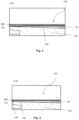
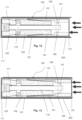
- the firearm obstructer 100 comprises an arm 101, and a body 103 having a tapered region 105.
- the arm 101 is arranged to move relative to the tapered region 105 to transition the firearm obstructer 100 between locking and unlocking configurations.
- the firearm obstructer 100 is positioned in the passage 200 between the chamber and the muzzle of a firearm and in this particular example is positioned in the breech-end of the barrel 200 of the firearm.
- Firearm obstructers 100 may be positioned in the chamber or the muzzle of the firearm, with corresponding changes to dimensions but the same mode of operation. It is, however, generally expected that the firearm obstructer 100 will be positioned in the breech-end of the barrel 200 of the firearm, so as to prevent a projectile being loaded into and subsequently discharged from the firearm.
- the firearm obstructer 100 is shown in the unlocking configuration, in which the firearm obstructer 100 is removable from the passage 200.
- the firearm obstructer 100 engages with the passage 200 to hold the firearm obstructer 100 in place in the passage. In this way, the firearm obstructer 100 obstructs the passage 200 between the chamber and the muzzle of the firearm, thereby preventing the discharge of the firearm.
- the firearm obstructer 100 is positioned in the passage 200 between the chamber and the muzzle of the firearm.
- the firearm obstructer 100 is initially in the unlocking configuration as shown in Figure 1 .
- the user transitions the firearm obstructer 100 to the locking configuration by moving the arm 101 relative to the tapered region 105.
- FIG. 2 there is shown the firearm obstructer 100 transitioning to the locking configuration.
- the arm 101 has moved towards the body 103 in the axial direction as compared to the unlocking configuration shown in Figure 1 .
- the movement towards the body 103 moves the arm 101 over the tapered region 105 which moves the arm 101 outwards in the radial direction.
- the radial outward movement of the arm 101 places the arm 101 in engagement with the passage 200.
- FIG. 3 there is shown the firearm obstructer 100 in the locking configuration.
- the arm 101 has moved further axially towards the body 103 as compared to Figure 2 .
- the arm 101 has been moved further radially outwards and into further engagement with the passage 200.
- the firearm obstructer 100 obstructs the passage 200 between the chamber and the muzzle of the firearm, thereby preventing the discharge of the firearm, and as described in greater detail below is held in place so that unauthorised removal is prevented.
- the firearm obstructer 100 has a first end portion 117 and a second end portion 129.
- the axial direction is from the first end portion 117 to the second end portion 129 and the radial direction is perpendicular to the axial direction.
- the arm 101 is arranged to move relative to the tapered region 105 in the axial direction to transition the firearm obstructer 100 between the locking and unlocking configurations.
- the first end portion 117 is a wide portion 117.
- the second end portion 129 is a narrow portion 129.
- the wide portion 117 is wider than the diameter of the passage 200. In use, the narrow portion 129 is inserted into the passage 200 of the firearm and the wide portion 117 is positioned outside of the passage 200 of the firearm.
- the wide portion 117 is in the form of an end cap 117.
- the end cap 117 is in the form of a disc and has a central aperture 183.
- the aperture 183 may be used to enable a key to access a lock of the firearm obstructer 100.
- the lock is discussed in greater detail below.
- the narrow portion 129 has a first end 131 and a second end 133.
- the first end 131 of the narrow portion 129 is connected to the wide portion 117 and the second end 133 of the narrow portion 129 is connected to an end cap 119.
- the end cap 119 is fixedly attached to the rest of the narrow portion 129 such as by being bolted to the rest of the narrow portion 129.
- the end cap 119 acts to prevent access to the internal components of the firearm obstructer 100.
- the end cap 119 is in the form of a disc and has two apertures 181 through which bolts may be received for fastening the end cap 119 to the rest of the narrow portion 129.
- the wide portion 117 is connected to the narrow portion 129 by a frangible connection arranged to break in response to a predetermined amount of force being applied to the wide portion 117. This means that if a force equal to or in excess of the predetermined amount of force is applied to the wide portion 117, the frangible connection breaks.
- the predetermined amount of force may be selected to be sufficiently high to prevent accidental removal of the wide portion 117.
- the predetermined amount of force may be selected such that the connection between the wide portion 117 and the narrow portion 129 breaks before sufficient force is applied to the firearm obstructer 100 to remove it from the passage 200 when in the locking configuration.
- the frangible connection may be provided by using an adhesive to bond the wide portion 117 to the narrow portion 129.
- This arrangement means that if, in use, an unauthorised user pulls on the wide portion 117, in an attempt to pull the firearm obstructer 100 out of the passage 200, the wide portion 117 will separate from the narrow portion 129.
- the narrow portion 129 will remain within the passage 200 meaning that there is no part of the firearm obstructer 100 extending out of the passage 200 that could be used to attempt to pull or pry the firearm obstructer 100 out of the passage 200.
- the tapered region 105 of the body 103 is tapered in the axial direction such that the width of the tapered region 105 increases in the direction from the second end 133 of the narrow portion 129 to the first end 131 of the narrow portion 129.
- the body 103 is generally cone-shaped and has an internal aperture running from one end to the other.
- At least part of the tapered region 105 is received within an internal aperture defined by the arms 101.
- the arm 101 moves over the tapered region 105 and is in contact with the tapered region 105. If the arm 101 moves axially towards the first end 131 of the narrow portion 129 then the arm 101 is urged outwardly in the radial direction due to the direction of taper of the tapered region 105. By contrast, if the arm 101 moves axially towards the second end 133 of the narrow portion 129 the arm 101 moves radially inwards.
- the firearm obstructer 100 further comprises a locking member indicated generally by the reference numeral 111.
- the movement of the arm 101 relative to the tapered region 105 is caused by the locking member 111.
- the locking member 111 is rotatable, and this rotation of the locking member 111 causes the arm 101 to move relative to the tapered region 105.
- the locking member 111 comprises a lock 143 and a threaded shaft 115.
- the threaded shaft 115 is arranged to extend from the first end 131 of the narrow portion 129 towards the second end 133 of the narrow portion 129.
- the threaded shaft 115 is received within the internal aperture of the arm 101 and the body 103.
- Figure 1 only shows a simplified form of the lock, but the skilled person will appreciate that a multi-pin lock could be used in place of the simplified lock 143 shown in Figure 1 .
- the lock 143 is configured to receive a key (not shown).
- the locking member 111 may cooperate with the key such that rotation of the key rotates the locking member 111.
- the key may be angled and incorporate a torque limiter.
- the torque limiter may be pre-set at manufacture.
- the threaded shaft 115 has a threaded region 113.
- the locking member 111 further comprises an advancer 107 that is connected to the threaded region 113 of the threaded shaft 115 and is connected to the arm 101.
- the advancer 107 acts to connect the arm 101 to the locking member 111 such that rotation of the locking member 111 effects movement of the arm 101 relative to the tapered region 105
- the firearm obstructer 100 is positioned in the passage 200 while in the unlocking configuration.
- the key is inserted into the lock 143 and rotated.
- Rotation of the key in the lock 143 causes the threaded shaft 115 to rotate.
- Rotation of the threaded shaft 115 draws the advancer 107 along the threaded shaft 115. With this motion, the arm 101 impinges on and moves over the tapered region 105, and the arm 101 moves radially outwardly.
- the threaded shaft 115 is caused to rotate, and this rotation causes the advancer 107 to move along the threaded shaft 115 in a direction towards to the first end 131 of the narrow portion 129.
- the movement of the advancer 107 causes the arm 101 to move over the tapered region 105 in a direction towards the first end 131 of the narrow portion 129.
- the tapered region 105 widens in the direction towards the first end 131 of the narrow portion 129.
- Continued rotation of the key in this direction causes the arm 101 to move radially outwards into engagement with the passage 200 in which the firearm obstructer 100 is located.
- the amount of pressure between the arms 135 and the material of the passage 200 e.g. the barrel of the firearm
- the key is rotated counter-clockwise, for example, and the advancer 107 moves away from the first end 131 and towards the second end 133 of the narrow portion 129.
- the movement of the advancer 107 causes the arm 101 to move in a direction towards the second end 133 of the narrow portion 129.
- the tapered region 105 narrows in the direction towards the second end 133 of the narrow portion 129.
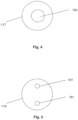
- the firearm obstructer 100 comprises a coupling portion 135 from which the arm 101 extends.
- the coupling portion 135 is integrally formed with the arm 101 in the example of Figure 1 .
- the coupling portion 135 may be considered as an extension of, or more generally a part of the arm 101.
- the firearm obstructer 100 may have one arm 101, two arms 101, or three or more arms 101.
- the arms 101 may comprise a sleeve separated by a plurality of slits/cut-outs. The particular number of arms 101 can be selected as desired.
- the arms 101 and/or coupling portion 135 comprise a resilient, flexible material such that extension of the arms 101 in the radial direction takes place by elastic flexion of the arms 101.
- the arms 101 and/or coupling portion 135 may bend resiliently from a portion away from the free end of the arm 101.
- the plurality of arms 101 extend from the coupling portion 135 in the axial direction.
- the coupling portion 135 has an annular cross-section.
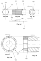
- the plurality of arms 101 extend around the circumference of the coupling portion 135. There are sixteen such arms 101 shown in Figure 6a but the present invention is not limited to any particular number of arms 101.
- the coupling portion 135 and arms 101 define an internal aperture.
- the arms 101 and coupling portion 135 of Figures 4a-4d therefore effectively form a lantern-ring.
- the end portions 141 of the arms 101 are tapered in the axial direction such that the tips 185 of the arms 101 are the narrowest points of the arms 101.
- the tapered surface 141 of the arms 101 face the tapered region 105 ( Figure 1 ).
- the advancer 107 is connected to the arm 101 by one or more shear pins 109.
- the shear pins 109 connect the advancer 107 to the coupling portion 135.
- the shear pins 109 are arranged to break in response to a predetermined amount of shear force being applied to the connection.
- the shear pins 109 breaking results in the locking member 111 being separated from the arm 101 because, in this example, the advancer 107 is no longer connected to the coupling 135. As a result, rotation of the locking member 111 is not able to cause movement of the arm 101.
- connection between the locking member 111 and the arm 101 is arranged to break in response to a predetermined amount of shear force being applied to the connection.
- the shear force may be applied as a result of an unauthorised user applying a percussive force to the firearm obstructer 100 in an attempt to dislodge the firearm obstructer 100 from the passage 200 when the firearm obstructer 100 is in the locking configuration. Therefore, the breakable connection between the locking member 111 and the arm 101 provides a security measure that prevents unauthorised removal of the firearm obstructer 100.
- the body 103 comprises a first body 103 having the tapered region 105 and a second body 123.
- the first body 103 has an end portion 125 that defines an aperture sized to receive the second body 123.
- the second body 123 is separated from and not directly contacting the first body 103.
- the second body 123 normally remains at a fixed distance relative to the first body 103.
- the end portion 125 of the first body 103 is in the form of a collet 125.
- the collet 125 forms a collar around the aperture of the first body 103.
- the collet 125 has a plurality of arms 126 positioned around the circumference of the aperture and separated by slits 127.
- the plurality of arms 126 are tapered in the axial direction. The taper extends in the same direction as the tapered region 105.
- the second body 123 has a first region 191 and a tapered region 193.
- the first region 191 and the tapered region 193 both have an internal aperture.
- the second body 123 and the first body 103 remain at a fixed position relative to one another.
- the second body 123 In response to a predetermined amount of force being applied to the second body 123, the second body 123 is arranged to be driven into the aperture of the collet 125 such that the second body 123 is at least partially retained within the aperture of the collet 125.
- the second body 123 being driven into the first body 103 acts to expand the collet 125 outwardly in the radial direction to form a locking configuration.
- the collet 125 engages the passage 200 to hold the firearm obstructer 100 in position with the passage 200.
- the firearm obstructer 100 so positioned provides an obstruction in the passage 200.
- the outer surface of the second body 123 is tapered due to tapered region 193. As the second body 123 is driven further into the aperture of the collet 125, the collet 125 expands further outwardly to form a tighter locking configuration.
- the firearm obstructer 100 further comprises an outer casing 121 arranged to at least partially encase the arm 101 and the body 103 of the firearm obstructer 100.
- the outer casing 121 entirely encases the narrow portion 129 of the firearm obstructer 100.
- the outer casing 121 is formed of a pliant material so as to provide protection to the inner surface of the passage 200.
- the outer casing 121 protects the passage 200, thereby preventing the firearm from being damaged as a result of the firearm obstructer 100 engaging with the passage 200.
- the outer casing 121 provides further enhancement to the locking configuration.
- the outer casing 121 in the locking configuration, forms a 'bow-wave' of material 149 at the ends of the arms 101 as shown in Figure 3 .
- This 'bow-wave' effect provides additional resistance against an attempted removal of the firearm obstructer 100 by force.
- the outer casing 121 is a flexible non-metallic sleeve.
- the outer casing 121 is formed of rubber or a composite material.
- the outer casing 121 is constructed from a material that is arranged to deform and expand in response to heat. As a result the firearm obstructer 100 may form a tighter engagement with the passage 200 in the event that heat is applied to the firearm.
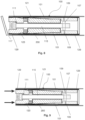
- FIG. 8 to 11 An operation whereby an unauthorised user attempts to remove the firearm obstructer 100 from the passage 200 by force when in the locking configuration will now be explained with reference to Figures 8 to 11 .
- the firearm obstructer 100 of Figures 8 to 11 is the same as the firearm obstructer 100 of Figure 1 .
- the same reference numerals have been used for convenience.
- the unauthorised user is attempting to remove the firearm obstructer 100 via the breech end of the barrel in which the firearm obstructer 100 is positioned.
- the unauthorised user may attempt to remove the firearm obstructer 100 by pulling or prying the wide portion 117 of the firearm obstructer 100.
- FIG 8 there is shown an arrangement of the firearm obstructer 100 as a result of an unauthorised user attempting to pull or pry the firearm obstructer 100 out of the passage 200.
- the wide portion 117 has separated from the narrow portion 129 of the firearm obstructer 100. This is because the connection between the wide portion 117 and the narrow portion 129 is arranged to break in response to a predetermined amount of force as explained previously.
- the application of the axial force results in the shear pins 109 breaking. This separates the locking member from the arm 101, and as such, the locking member 111 is unable to cause movement of the arm 101 to transition the arm 101 out of the locking configuration.
- the axial force results in the second body 123 being drive into the aperture of the collet 125 such that the collet 125 expands outwardly to engage the passage 200.
- the collet 125 engaging the passage 200 is shown in Figure 11 . This essentially forms a second locking configuration for the firearm obstructer 100 such that the firearm obstructer 100 is held in an even securer position with the passage 200.
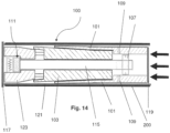
- FIG. 12 to 14 Another operation whereby an unauthorised user attempts to remove the firearm obstructer 100 from the passage 200 by force when in the locking configuration will now be explained with reference to Figures 12 to 14 .
- the firearm obstructer 100 of Figures 12 to 14 is the same as the firearm obstructer 100 of Figure 1 .
- the same reference numerals have been used for convenience.
- the unauthorised user is attempting to remove the firearm obstructer 100 via the muzzle end of the barrel.
- the firearm obstructer 100 is positioned in the breech end of the barrel.
- the unauthorised user may place an object in the muzzle end of the barrel and use this object to apply a force to the firearm obstructer 100 in an attempt to dislodge the firearm obstructer 100.
- the application of the force for example a percussive force, is indicated by the directional arrows in Figure 12 .
- the firearm obstructer 100 of the first aspect may prevent unauthorised attempts to remove the firearm obstructer 100 from one or both ends of the firearm (e.g. breech-end and/or muzzle end).
- the firearm obstructer 100 may further comprise a container (not shown) arranged to contain an adhesive material.
- the container is arranged to rupture in response to a predetermined amount of force being applied to the container such that the adhesive contained within the container is released so as to adhesively bond the firearm obstructer 100 in position.
- the container of adhesive material provides a further security measure to prevent unauthorised use of the firearm.
- the firearm obstructer 100 may have a length that is similar to that of a typical projectile/ammunition round for the firearm that the firearm obstructer 100 is intended to be used with. For example, in the case of a 12-bore shotgun, the typical overall length of the firearm obstructer 100 would be approximately 7 cm. In the case of a contemporary current military or police firearm ammunition round, the typical overall length would be between 2.5 cm and 5 cm. It will be appreciated that the length of the firearm obstructer 100 will be dependent on the firearm for which the firearm obstructer 100 is intended to be used with. The firearm obstructer 100 may have a length less than or equal to 7 cm.
- the narrow portion 129 of the firearm obstructer 100 may have a diameter that is similar to that of a typical projectile/ammunition round for the firearm that the firearm obstructer 100 is intended to be used with. It will be appreciated that the diameter of the narrow portion 129 of the firearm obstructer 100 will be dependent on the firearm for which the firearm obstructer 100 is intended to be used with. For example, in the case of a 12-bore shotgun, the typical diameter of the narrow portion 129 of the firearm obstructer 100 when in the locking configuration would be approximately 2 cm. The narrow portion 129 of the firearm obstructer 100 may have a diameter of less than or equal to 2 cm when in the locking configuration.
- the wide portion 117 of the firearm obstructer 100 may have a diameter slightly larger than the diameter of a typical projectile/ammunition round that the firearm obstructer 100 is intended to be used with.
- the diameter of the wide portion 117 may be minimally sufficient to prevent the device from totally entering the breech of the firearm, for example.
- the diameter of the wide portion 117 is approximately 0.14 mm greater than the diameter of the narrow portion 129 when the narrow portion 129 is in the locking configuration.
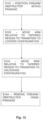
- FIG. 15 there is shown a method according to the second aspect for operating the firearm obstructer 100.
- step S101 the firearm obstructer 100 is positioned within the passage 200 between the chamber and the muzzle of the firearm while in the unlocking configuration.
- step S102 the arm 101 is moved relative to the tapered region 105 to transition the firearm obstructer 100 from the unlocking configuration to the locking configuration.
- the firearm obstructer 100 is securely positioned within the passage 200 such that the firearm obstructer 100 obstructs the passage 200.
- step S103 in order to remove the firearm obstructer 100 from the passage 200, the arm 101 is moved relative to the tapered region 105 to transition the firearm obstructer 100 from the locking configuration to the unlocking configuration.
- step S104 the firearm obstructer 100 is removed from the passage 200.
- a firearm obstructer 100 for obstructing a passage 200 between a chamber and a muzzle of a firearm.
- the firearm obstructer 100 has an arm 101 and a tapered region 105.
- the arm 101 moves relative to the tapered region 105 to transition the firearm obstructer 100 between locking and unlocking configurations.
- the firearm obstructer 100 engages with the passage 200 to hold the firearm obstructer 100 in place in the passage 200.
- the firearm obstructer 100 so positioned provides an obstruction in the passage 200.
- the firearm obstructer 100 is removable from the passage 200.
- a method of operating the same is also provided.
Landscapes
- Engineering & Computer Science (AREA)
- General Engineering & Computer Science (AREA)
- Portable Nailing Machines And Staplers (AREA)
- Aiming, Guidance, Guns With A Light Source, Armor, Camouflage, And Targets (AREA)
Claims (15)
- Schusswaffenblockiervorrichtung (100), die zur Verwendung beim Blockieren eines Durchgangs zwischen einer Kammer und einer Mündung einer Schusswaffe geeignet ist, wobei die Schusswaffenblockiervorrichtung (100) umfasst: einen Arm (101) und einen Körper (103) mit einem sich verjüngenden Bereich (105),wobei der Arm (101) so angeordnet ist, dass er sich relativ zum sich verjüngenden Bereich (105) bewegt, um die Schusswaffenblockiervorrichtung (100) zwischen Verriegelungs- und Entriegelungskonfigurationen zu überführen,wobei in der Verriegelungskonfiguration die Schusswaffenblockiervorrichtung (100) so angeordnet ist, dass sie in den Durchgang eingreift, um die Schusswaffenblockiervorrichtung (100) an Ort und Stelle in dem Durchgang zu halten, und wobei die so positionierte Schusswaffenblockiervorrichtung (100) eine Blockierung in dem Durchgang bereitstellt, undwobei in der Entriegelungskonfiguration die Schusswaffenblockiervorrichtung (100) aus dem Durchgang herausnehmbar ist; undferner umfassend ein Verriegelungselement (111), wobei das Verriegelungselement (111) mit dem Arm (101) verbunden ist, um die relative Bewegung zwischen dem Arm (101) und dem sich verjüngenden Bereich (105) zu bewirken, und wobei eine Drehung des Verriegelungselements (111) eine relative Bewegung des Arms (101) und des sich verjüngenden Bereichs (105) bewirkt, und wobei eine Drehung des Verriegelungselements (111) in eine Richtung eine relative Bewegung des Arms (101) und des sich verjüngenden Bereichs (105) bewirkt, um die Schusswaffenblockiervorrichtung (100) in die Verriegelungskonfiguration zu überführen, während eine Drehung des Verriegelungselements (111) in eine entgegengesetzte Richtung ein Überführen der Schusswaffenblockiervorrichtung (100) in die Entriegelungskonfiguration ermöglicht; undwobei die Schusswaffenblockiervorrichtung (100) ferner einen Vorschub (107) umfasst, wobei der Vorschub (107) den Arm (101) mit dem Verriegelungselement (111) verbindet, und wobei die Verbindung zwischen dem Arm (101) und dem Vorschub (107) so angeordnet ist, dass sie in Reaktion darauf, dass der vorgegebene Betrag an Kraft auf die Verbindung aufgebracht wird, bricht, um den Vorschub (107) vom Arm (101) zu trennen.
- Schusswaffenblockiervorrichtung (100) nach Anspruch 1, wobei die Schusswaffenblockiervorrichtung (100) einen breiten Abschnitt und einen schmalen Abschnitt aufweist, wobei der schmale Abschnitt den Körper (103) und den Arm (101) umfasst, wobei in Verwendung der schmale Abschnitt in den Durchgang der Schusswaffe eingeführt ist und der breite Abschnitt außerhalb des Durchgangs der Schusswaffe positioniert ist.
- Schusswaffenblockiervorrichtung (100) nach Anspruch 2, wobei der breite Abschnitt mit dem schmalen Abschnitt durch eine zerbrechliche Verbindung verbunden ist, die so angeordnet ist, dass sie in Reaktion darauf, dass ein vorgegebener Betrag an Kraft auf den breiten Abschnitt aufgebracht wird, bricht, um den breiten Abschnitt vom schmalen Abschnitt zu trennen, so dass in Verwendung der schmale Abschnitt im Durchgang der Schusswaffe verbleiben kann.
- Schusswaffenblockiervorrichtung (100) nach einem der vorhergehenden Ansprüche, wobei das Verriegelungselement (111) mit einem Schlüssel zusammenwirkt, so dass durch eine Drehung des Schlüssels das Verriegelungselement (111) gedreht wird.
- Schusswaffenblockiervorrichtung (100) nach Anspruch 4, wobei der Vorschub (107) durch einen oder mehrere Scherstifte mit dem Arm (101) verbunden ist.
- Schusswaffenblockiervorrichtung (100) nach einem der vorhergehenden Ansprüche, wobei das Verriegelungselement (111) eine Gewindewelle umfasst, wobei der Vorschub (107) optional mit der Gewindewelle verbunden ist.
- Schusswaffenblockiervorrichtung (100) nach einem der vorhergehenden Ansprüche, wobei die Schusswaffenblockiervorrichtung (100) einen Kopplungsabschnitt aufweist, von dem sich der Arm (101) erstreckt.
- Schusswaffenblockiervorrichtung (100) nach Anspruch 7, wobei die Schusswaffenblockiervorrichtung (100) eine Mehrzahl von Armen umfasst, wobei der Kopplungsabschnitt einen ringförmigen Querschnitt aufweist, und wobei sich die Mehrzahl von Armen um den Umfang des Kopplungsabschnitts erstreckt.
- Schusswaffenblockiervorrichtung (100) nach Anspruch 8, wobei die Mehrzahl von Armen eine innere Öffnung zum Aufnehmen zumindest eines Teils des sich verjüngenden Bereichs definiert, und wobei, während sich die Arme über den sich verjüngenden Bereich (105) bewegen, der sich verjüngende Bereich (105) die Mehrzahl von Armen nach außen drückt, um die Verriegelungskonfiguration zu bilden.
- Schusswaffenblockiervorrichtung (100) nach einem der vorhergehenden Ansprüche, wobei der Körper (103) einen ersten Körper mit dem sich verjüngenden Bereich (105) und einen zweiten Körper umfasst, wobei während einer normalen Verwendung der zweite Körper und der erste Körper in einer festen Position relativ zueinander verbleiben.
- Schusswaffenblockiervorrichtung (100) nach Anspruch 10, wobei der erste Körper einen Endabschnitt aufweist, der eine Öffnung definiert, die zum Aufnehmen des zweiten Körpers dimensioniert ist, und wobei der zweite Körper so angeordnet ist, dass er in Reaktion darauf, dass ein vorgegebener Betrag an Kraft auf den zweiten Körper aufgebracht wird, in die Öffnung getrieben wird, so dass der zweite Körper zumindest teilweise innerhalb der Öffnung des ersten Körpers gehalten ist.
- Schusswaffenblockiervorrichtung (100) nach Anspruch 11, wobei der Endabschnitt die Form einer Klemmhülse aufweist, wobei, wenn der zweite Körper in die Öffnung der Klemmhülse getrieben wird, sich die Klemmhülse nach außen ausdehnt, um eine Verriegelungskonfiguration zu bilden, und wobei in der Verriegelungskonfiguration die Außenfläche der Klemmhülse so angeordnet ist, dass sie in den Durchgang der Schusswaffe eingreift, um die Schusswaffenblockiervorrichtung (100) in Position mit dem Durchgang zu halten, und wobei die so positionierte Schusswaffenblockiervorrichtung (100) eine Blockierung in dem Durchgang bereitstellt, wobei optional eine Außenfläche des zweiten Körpers verjüngt ist, so dass sich das Sammeln, während der zweite Körper weiter in die Öffnung der Klemmhülse getrieben wird, weiter nach außen ausdehnt, um eine engere Verriegelungskonfiguration zu bilden.
- Schusswaffenblockiervorrichtung (100) nach einem der vorhergehenden Ansprüche, ferner umfassend eine Außenhülle, die so angeordnet ist, dass sie den Arm und den Körper der Schusswaffenblockiervorrichtung (100) zumindest teilweise umhüllt, wobei die Außenhülle optional aus einem biegsamen Material gebildet ist.
- Schusswaffenblockiervorrichtung (100) nach einem der vorhergehenden Ansprüche, ferner umfassend einen Behälter, der dazu angeordnet ist, ein Klebstoffmaterial zu enthalten, wobei der Behälter so angeordnet ist, dass er in Reaktion darauf, dass ein vorgegebener Betrag an Kraft auf den Behälter aufgebracht wird, reißt, so dass der im Behälter enthaltene Klebstoff freigesetzt wird, um die Schusswaffenblockiervorrichtung (100) in ihrer Position zu verkleben.
- Verfahren zum Betätigen einer Schusswaffenblockiervorrichtung (100) nach einem der vorhergehenden Ansprüche, wobei das Verfahren umfasst:Positionieren der Schusswaffenblockiervorrichtung (100) innerhalb des Durchgangs zwischen der Kammer und der Mündung der Schusswaffe; undBewegen des Arms relativ zum sich verjüngenden Bereich, um die Schusswaffenblockiervorrichtung (100) von der Entriegelungskonfiguration in die Verriegelungskonfiguration zu überführen.
Applications Claiming Priority (2)
| Application Number | Priority Date | Filing Date | Title |
|---|---|---|---|
| GBGB1711989.2A GB201711989D0 (en) | 2017-07-25 | 2017-07-25 | Firearm obstructer and methods of operating the same |
| PCT/GB2018/052090 WO2019020996A1 (en) | 2017-07-25 | 2018-07-25 | FIREARM OBSTRUCTION DEVICE AND METHODS OF ACTUATION |
Publications (3)
| Publication Number | Publication Date |
|---|---|
| EP3658846A1 EP3658846A1 (de) | 2020-06-03 |
| EP3658846C0 EP3658846C0 (de) | 2024-12-04 |
| EP3658846B1 true EP3658846B1 (de) | 2024-12-04 |
Family
ID=59771768
Family Applications (1)
| Application Number | Title | Priority Date | Filing Date |
|---|---|---|---|
| EP18752207.3A Active EP3658846B1 (de) | 2017-07-25 | 2018-07-25 | Schusswaffenblockierer und verfahren zur handhabung davon |
Country Status (5)
| Country | Link |
|---|---|
| US (1) | US10941996B2 (de) |
| EP (1) | EP3658846B1 (de) |
| CA (1) | CA3070887A1 (de) |
| GB (2) | GB201711989D0 (de) |
| WO (1) | WO2019020996A1 (de) |
Families Citing this family (3)
| Publication number | Priority date | Publication date | Assignee | Title |
|---|---|---|---|---|
| US11262147B2 (en) | 2019-08-23 | 2022-03-01 | AmmoBlock LLC | Firearm safety device |
| IT202300000414A1 (it) * | 2023-01-13 | 2024-07-13 | Prefer Srl | Dispositivo di sicurezza anti-sparo per una canna di arma da fuoco |
| US12209850B1 (en) * | 2024-04-23 | 2025-01-28 | Ningbo Jiuli CNC Machinery Co., Ltd | Dummy ammo and use method thereof |
Family Cites Families (7)
| Publication number | Priority date | Publication date | Assignee | Title |
|---|---|---|---|---|
| US3154874A (en) * | 1963-03-26 | 1964-11-03 | Albert R Stewart | Gun lock |
| US5699687A (en) * | 1996-06-06 | 1997-12-23 | Pittman; John M. | Firearm security device |
| US5950344A (en) | 1997-10-30 | 1999-09-14 | Ross; Larry | Quick-release gun lock |
| US6584718B1 (en) * | 2000-10-13 | 2003-07-01 | Anthony F. Serrao | Firearm locking mechanism |
| DE10231685B4 (de) * | 2002-07-12 | 2006-09-28 | Armatix Gmbh | Schusswaffensicherung |
| DE102006062731B4 (de) * | 2006-03-10 | 2009-07-09 | Armatix Gmbh | Vorrichtung zur Aufbewahrung einer Schusswaffe |
| US9464461B2 (en) * | 2012-08-31 | 2016-10-11 | Ron R. Daniels | Lock device and method of use |
-
2017
- 2017-07-25 GB GBGB1711989.2A patent/GB201711989D0/en not_active Ceased
-
2018
- 2018-07-25 US US16/633,058 patent/US10941996B2/en active Active
- 2018-07-25 EP EP18752207.3A patent/EP3658846B1/de active Active
- 2018-07-25 GB GB2002566.4A patent/GB2581589B/en active Active
- 2018-07-25 WO PCT/GB2018/052090 patent/WO2019020996A1/en not_active Ceased
- 2018-07-25 CA CA3070887A patent/CA3070887A1/en active Pending
Also Published As
| Publication number | Publication date |
|---|---|
| US20200173747A1 (en) | 2020-06-04 |
| GB202002566D0 (en) | 2020-04-08 |
| GB201711989D0 (en) | 2017-09-06 |
| EP3658846C0 (de) | 2024-12-04 |
| US10941996B2 (en) | 2021-03-09 |
| WO2019020996A1 (en) | 2019-01-31 |
| EP3658846A1 (de) | 2020-06-03 |
| GB2581589B (en) | 2022-10-19 |
| GB2581589A (en) | 2020-08-26 |
| CA3070887A1 (en) | 2019-01-31 |
Similar Documents
| Publication | Publication Date | Title |
|---|---|---|
| EP3658846B1 (de) | Schusswaffenblockierer und verfahren zur handhabung davon | |
| US5048211A (en) | Safety lock for firearms | |
| EP0412990B1 (de) | Sicherheitsverriegelung für feuerwaffen | |
| US9222742B2 (en) | Self-locking firearm safety device and process for securing a firearm | |
| CA2878874C (en) | Safety system for a hand gun to prevent unauthorized use | |
| US5239767A (en) | High security gun lock device | |
| US4969284A (en) | Shotgun disabling device | |
| US7930975B2 (en) | Deconfinement device for the casing of a piece of an ammunition | |
| US6405472B1 (en) | Gun lock safety device | |
| USRE48602E1 (en) | Gun safety device | |
| US5044105A (en) | Locking device | |
| US9803944B2 (en) | Gun safety device | |
| US6584718B1 (en) | Firearm locking mechanism | |
| US10190838B2 (en) | Gun safety device | |
| GB2215822A (en) | Locking device for firearms | |
| US6502344B1 (en) | Safety mechanism for preventing unauthorized use of a firearm | |
| US20030172572A1 (en) | Firearm safety apparatus and methods | |
| US7121033B1 (en) | Gun lock | |
| US20180094890A1 (en) | Gun safety device | |
| WO1992021928A1 (en) | Firearms lock | |
| HK1208064B (en) | Safety system for a hand gun to prevent unauthorized use | |
| PL224100B1 (pl) | Nabój moździerzowy |
Legal Events
| Date | Code | Title | Description |
|---|---|---|---|
| STAA | Information on the status of an ep patent application or granted ep patent |
Free format text: STATUS: UNKNOWN |
|
| STAA | Information on the status of an ep patent application or granted ep patent |
Free format text: STATUS: THE INTERNATIONAL PUBLICATION HAS BEEN MADE |
|
| PUAI | Public reference made under article 153(3) epc to a published international application that has entered the european phase |
Free format text: ORIGINAL CODE: 0009012 |
|
| STAA | Information on the status of an ep patent application or granted ep patent |
Free format text: STATUS: REQUEST FOR EXAMINATION WAS MADE |
|
| 17P | Request for examination filed |
Effective date: 20200224 |
|
| AK | Designated contracting states |
Kind code of ref document: A1 Designated state(s): AL AT BE BG CH CY CZ DE DK EE ES FI FR GB GR HR HU IE IS IT LI LT LU LV MC MK MT NL NO PL PT RO RS SE SI SK SM TR |
|
| AX | Request for extension of the european patent |
Extension state: BA ME |
|
| DAV | Request for validation of the european patent (deleted) | ||
| DAX | Request for extension of the european patent (deleted) | ||
| STAA | Information on the status of an ep patent application or granted ep patent |
Free format text: STATUS: EXAMINATION IS IN PROGRESS |
|
| 17Q | First examination report despatched |
Effective date: 20220302 |
|
| GRAP | Despatch of communication of intention to grant a patent |
Free format text: ORIGINAL CODE: EPIDOSNIGR1 |
|
| STAA | Information on the status of an ep patent application or granted ep patent |
Free format text: STATUS: GRANT OF PATENT IS INTENDED |
|
| INTG | Intention to grant announced |
Effective date: 20240627 |
|
| GRAS | Grant fee paid |
Free format text: ORIGINAL CODE: EPIDOSNIGR3 |
|
| GRAA | (expected) grant |
Free format text: ORIGINAL CODE: 0009210 |
|
| STAA | Information on the status of an ep patent application or granted ep patent |
Free format text: STATUS: THE PATENT HAS BEEN GRANTED |
|
| AK | Designated contracting states |
Kind code of ref document: B1 Designated state(s): AL AT BE BG CH CY CZ DE DK EE ES FI FR GB GR HR HU IE IS IT LI LT LU LV MC MK MT NL NO PL PT RO RS SE SI SK SM TR |
|
| REG | Reference to a national code |
Ref country code: GB Ref legal event code: FG4D |
|
| REG | Reference to a national code |
Ref country code: CH Ref legal event code: EP |
|
| REG | Reference to a national code |
Ref country code: DE Ref legal event code: R096 Ref document number: 602018077229 Country of ref document: DE |
|
| REG | Reference to a national code |
Ref country code: IE Ref legal event code: FG4D |
|
| U01 | Request for unitary effect filed |
Effective date: 20250102 |
|
| U07 | Unitary effect registered |
Designated state(s): AT BE BG DE DK EE FI FR IT LT LU LV MT NL PT RO SE SI Effective date: 20250114 |
|
| PG25 | Lapsed in a contracting state [announced via postgrant information from national office to epo] |
Ref country code: HR Free format text: LAPSE BECAUSE OF FAILURE TO SUBMIT A TRANSLATION OF THE DESCRIPTION OR TO PAY THE FEE WITHIN THE PRESCRIBED TIME-LIMIT Effective date: 20241204 |
|
| PG25 | Lapsed in a contracting state [announced via postgrant information from national office to epo] |
Ref country code: NO Free format text: LAPSE BECAUSE OF FAILURE TO SUBMIT A TRANSLATION OF THE DESCRIPTION OR TO PAY THE FEE WITHIN THE PRESCRIBED TIME-LIMIT Effective date: 20250304 |
|
| PG25 | Lapsed in a contracting state [announced via postgrant information from national office to epo] |
Ref country code: GR Free format text: LAPSE BECAUSE OF FAILURE TO SUBMIT A TRANSLATION OF THE DESCRIPTION OR TO PAY THE FEE WITHIN THE PRESCRIBED TIME-LIMIT Effective date: 20250305 |
|
| PG25 | Lapsed in a contracting state [announced via postgrant information from national office to epo] |
Ref country code: RS Free format text: LAPSE BECAUSE OF FAILURE TO SUBMIT A TRANSLATION OF THE DESCRIPTION OR TO PAY THE FEE WITHIN THE PRESCRIBED TIME-LIMIT Effective date: 20250304 |
|
| PG25 | Lapsed in a contracting state [announced via postgrant information from national office to epo] |
Ref country code: SM Free format text: LAPSE BECAUSE OF FAILURE TO SUBMIT A TRANSLATION OF THE DESCRIPTION OR TO PAY THE FEE WITHIN THE PRESCRIBED TIME-LIMIT Effective date: 20241204 |
|
| PG25 | Lapsed in a contracting state [announced via postgrant information from national office to epo] |
Ref country code: PL Free format text: LAPSE BECAUSE OF FAILURE TO SUBMIT A TRANSLATION OF THE DESCRIPTION OR TO PAY THE FEE WITHIN THE PRESCRIBED TIME-LIMIT Effective date: 20241204 |
|
| PG25 | Lapsed in a contracting state [announced via postgrant information from national office to epo] |
Ref country code: ES Free format text: LAPSE BECAUSE OF FAILURE TO SUBMIT A TRANSLATION OF THE DESCRIPTION OR TO PAY THE FEE WITHIN THE PRESCRIBED TIME-LIMIT Effective date: 20241204 |
|
| PG25 | Lapsed in a contracting state [announced via postgrant information from national office to epo] |
Ref country code: IS Free format text: LAPSE BECAUSE OF FAILURE TO SUBMIT A TRANSLATION OF THE DESCRIPTION OR TO PAY THE FEE WITHIN THE PRESCRIBED TIME-LIMIT Effective date: 20250404 |
|
| PG25 | Lapsed in a contracting state [announced via postgrant information from national office to epo] |
Ref country code: SK Free format text: LAPSE BECAUSE OF FAILURE TO SUBMIT A TRANSLATION OF THE DESCRIPTION OR TO PAY THE FEE WITHIN THE PRESCRIBED TIME-LIMIT Effective date: 20241204 |
|
| PG25 | Lapsed in a contracting state [announced via postgrant information from national office to epo] |
Ref country code: CZ Free format text: LAPSE BECAUSE OF FAILURE TO SUBMIT A TRANSLATION OF THE DESCRIPTION OR TO PAY THE FEE WITHIN THE PRESCRIBED TIME-LIMIT Effective date: 20241204 |
|
| PLBE | No opposition filed within time limit |
Free format text: ORIGINAL CODE: 0009261 |
|
| STAA | Information on the status of an ep patent application or granted ep patent |
Free format text: STATUS: NO OPPOSITION FILED WITHIN TIME LIMIT |
|
| 26N | No opposition filed |
Effective date: 20250905 |
|
| PGFP | Annual fee paid to national office [announced via postgrant information from national office to epo] |
Ref country code: GB Payment date: 20251219 Year of fee payment: 8 |
|
| U21 | Renewal fee for the european patent with unitary effect paid with additional fee |
Year of fee payment: 8 Effective date: 20251211 |
|
| PGFP | Annual fee paid to national office [announced via postgrant information from national office to epo] |
Ref country code: IE Payment date: 20251230 Year of fee payment: 8 |