EP3658814B1 - Load-stabilizing apparatus - Google Patents
Load-stabilizing apparatus Download PDFInfo
- Publication number
- EP3658814B1 EP3658814B1 EP19772213.5A EP19772213A EP3658814B1 EP 3658814 B1 EP3658814 B1 EP 3658814B1 EP 19772213 A EP19772213 A EP 19772213A EP 3658814 B1 EP3658814 B1 EP 3658814B1
- Authority
- EP
- European Patent Office
- Prior art keywords
- load
- arm
- stabilizing
- connecting arm
- parallelogram mechanism
- Prior art date
- Legal status (The legal status is an assumption and is not a legal conclusion. Google has not performed a legal analysis and makes no representation as to the accuracy of the status listed.)
- Active
Links
- 230000000087 stabilizing effect Effects 0.000 claims description 93
- 230000033001 locomotion Effects 0.000 claims description 19
- 238000001514 detection method Methods 0.000 claims description 5
- 230000006641 stabilisation Effects 0.000 description 59
- 238000011105 stabilization Methods 0.000 description 59
- 230000000903 blocking effect Effects 0.000 description 33
- 238000010586 diagram Methods 0.000 description 10
- 230000008054 signal transmission Effects 0.000 description 8
- 238000000034 method Methods 0.000 description 6
- 239000003381 stabilizer Substances 0.000 description 6
- 230000005540 biological transmission Effects 0.000 description 4
- 230000000694 effects Effects 0.000 description 3
- 230000006835 compression Effects 0.000 description 2
- 238000007906 compression Methods 0.000 description 2
- 230000005484 gravity Effects 0.000 description 2
- 238000005259 measurement Methods 0.000 description 2
- 230000009286 beneficial effect Effects 0.000 description 1
- 238000004891 communication Methods 0.000 description 1
- 230000001419 dependent effect Effects 0.000 description 1
- 238000005516 engineering process Methods 0.000 description 1
- 230000014509 gene expression Effects 0.000 description 1
- 238000000465 moulding Methods 0.000 description 1
- 230000002093 peripheral effect Effects 0.000 description 1
Images


Classifications
-
- F—MECHANICAL ENGINEERING; LIGHTING; HEATING; WEAPONS; BLASTING
- F16—ENGINEERING ELEMENTS AND UNITS; GENERAL MEASURES FOR PRODUCING AND MAINTAINING EFFECTIVE FUNCTIONING OF MACHINES OR INSTALLATIONS; THERMAL INSULATION IN GENERAL
- F16M—FRAMES, CASINGS OR BEDS OF ENGINES, MACHINES OR APPARATUS, NOT SPECIFIC TO ENGINES, MACHINES OR APPARATUS PROVIDED FOR ELSEWHERE; STANDS; SUPPORTS
- F16M11/00—Stands or trestles as supports for apparatus or articles placed thereon ; Stands for scientific apparatus such as gravitational force meters
- F16M11/20—Undercarriages with or without wheels
- F16M11/24—Undercarriages with or without wheels changeable in height or length of legs, also for transport only, e.g. by means of tubes screwed into each other
-
- F—MECHANICAL ENGINEERING; LIGHTING; HEATING; WEAPONS; BLASTING
- F16—ENGINEERING ELEMENTS AND UNITS; GENERAL MEASURES FOR PRODUCING AND MAINTAINING EFFECTIVE FUNCTIONING OF MACHINES OR INSTALLATIONS; THERMAL INSULATION IN GENERAL
- F16M—FRAMES, CASINGS OR BEDS OF ENGINES, MACHINES OR APPARATUS, NOT SPECIFIC TO ENGINES, MACHINES OR APPARATUS PROVIDED FOR ELSEWHERE; STANDS; SUPPORTS
- F16M13/00—Other supports for positioning apparatus or articles; Means for steadying hand-held apparatus or articles
- F16M13/04—Other supports for positioning apparatus or articles; Means for steadying hand-held apparatus or articles for supporting on, or holding steady relative to, a person, e.g. by chains, e.g. rifle butt or pistol grip supports, supports attached to the chest or head
-
- F—MECHANICAL ENGINEERING; LIGHTING; HEATING; WEAPONS; BLASTING
- F16—ENGINEERING ELEMENTS AND UNITS; GENERAL MEASURES FOR PRODUCING AND MAINTAINING EFFECTIVE FUNCTIONING OF MACHINES OR INSTALLATIONS; THERMAL INSULATION IN GENERAL
- F16M—FRAMES, CASINGS OR BEDS OF ENGINES, MACHINES OR APPARATUS, NOT SPECIFIC TO ENGINES, MACHINES OR APPARATUS PROVIDED FOR ELSEWHERE; STANDS; SUPPORTS
- F16M11/00—Stands or trestles as supports for apparatus or articles placed thereon ; Stands for scientific apparatus such as gravitational force meters
- F16M11/02—Heads
- F16M11/04—Means for attachment of apparatus; Means allowing adjustment of the apparatus relatively to the stand
- F16M11/06—Means for attachment of apparatus; Means allowing adjustment of the apparatus relatively to the stand allowing pivoting
- F16M11/12—Means for attachment of apparatus; Means allowing adjustment of the apparatus relatively to the stand allowing pivoting in more than one direction
- F16M11/121—Means for attachment of apparatus; Means allowing adjustment of the apparatus relatively to the stand allowing pivoting in more than one direction constituted of several dependent joints
- F16M11/123—Means for attachment of apparatus; Means allowing adjustment of the apparatus relatively to the stand allowing pivoting in more than one direction constituted of several dependent joints the axis of rotation intersecting in a single point, e.g. by using gimbals
-
- F—MECHANICAL ENGINEERING; LIGHTING; HEATING; WEAPONS; BLASTING
- F16—ENGINEERING ELEMENTS AND UNITS; GENERAL MEASURES FOR PRODUCING AND MAINTAINING EFFECTIVE FUNCTIONING OF MACHINES OR INSTALLATIONS; THERMAL INSULATION IN GENERAL
- F16M—FRAMES, CASINGS OR BEDS OF ENGINES, MACHINES OR APPARATUS, NOT SPECIFIC TO ENGINES, MACHINES OR APPARATUS PROVIDED FOR ELSEWHERE; STANDS; SUPPORTS
- F16M11/00—Stands or trestles as supports for apparatus or articles placed thereon ; Stands for scientific apparatus such as gravitational force meters
- F16M11/02—Heads
- F16M11/18—Heads with mechanism for moving the apparatus relatively to the stand
-
- F—MECHANICAL ENGINEERING; LIGHTING; HEATING; WEAPONS; BLASTING
- F16—ENGINEERING ELEMENTS AND UNITS; GENERAL MEASURES FOR PRODUCING AND MAINTAINING EFFECTIVE FUNCTIONING OF MACHINES OR INSTALLATIONS; THERMAL INSULATION IN GENERAL
- F16M—FRAMES, CASINGS OR BEDS OF ENGINES, MACHINES OR APPARATUS, NOT SPECIFIC TO ENGINES, MACHINES OR APPARATUS PROVIDED FOR ELSEWHERE; STANDS; SUPPORTS
- F16M11/00—Stands or trestles as supports for apparatus or articles placed thereon ; Stands for scientific apparatus such as gravitational force meters
- F16M11/20—Undercarriages with or without wheels
- F16M11/2007—Undercarriages with or without wheels comprising means allowing pivoting adjustment
- F16M11/2035—Undercarriages with or without wheels comprising means allowing pivoting adjustment in more than one direction
- F16M11/2071—Undercarriages with or without wheels comprising means allowing pivoting adjustment in more than one direction for panning and rolling
-
- F—MECHANICAL ENGINEERING; LIGHTING; HEATING; WEAPONS; BLASTING
- F16—ENGINEERING ELEMENTS AND UNITS; GENERAL MEASURES FOR PRODUCING AND MAINTAINING EFFECTIVE FUNCTIONING OF MACHINES OR INSTALLATIONS; THERMAL INSULATION IN GENERAL
- F16M—FRAMES, CASINGS OR BEDS OF ENGINES, MACHINES OR APPARATUS, NOT SPECIFIC TO ENGINES, MACHINES OR APPARATUS PROVIDED FOR ELSEWHERE; STANDS; SUPPORTS
- F16M11/00—Stands or trestles as supports for apparatus or articles placed thereon ; Stands for scientific apparatus such as gravitational force meters
- F16M11/20—Undercarriages with or without wheels
- F16M11/2092—Undercarriages with or without wheels comprising means allowing depth adjustment, i.e. forward-backward translation of the head relatively to the undercarriage
-
- G—PHYSICS
- G03—PHOTOGRAPHY; CINEMATOGRAPHY; ANALOGOUS TECHNIQUES USING WAVES OTHER THAN OPTICAL WAVES; ELECTROGRAPHY; HOLOGRAPHY
- G03B—APPARATUS OR ARRANGEMENTS FOR TAKING PHOTOGRAPHS OR FOR PROJECTING OR VIEWING THEM; APPARATUS OR ARRANGEMENTS EMPLOYING ANALOGOUS TECHNIQUES USING WAVES OTHER THAN OPTICAL WAVES; ACCESSORIES THEREFOR
- G03B17/00—Details of cameras or camera bodies; Accessories therefor
- G03B17/56—Accessories
- G03B17/561—Support related camera accessories
-
- F—MECHANICAL ENGINEERING; LIGHTING; HEATING; WEAPONS; BLASTING
- F16—ENGINEERING ELEMENTS AND UNITS; GENERAL MEASURES FOR PRODUCING AND MAINTAINING EFFECTIVE FUNCTIONING OF MACHINES OR INSTALLATIONS; THERMAL INSULATION IN GENERAL
- F16M—FRAMES, CASINGS OR BEDS OF ENGINES, MACHINES OR APPARATUS, NOT SPECIFIC TO ENGINES, MACHINES OR APPARATUS PROVIDED FOR ELSEWHERE; STANDS; SUPPORTS
- F16M11/00—Stands or trestles as supports for apparatus or articles placed thereon ; Stands for scientific apparatus such as gravitational force meters
- F16M11/02—Heads
- F16M11/04—Means for attachment of apparatus; Means allowing adjustment of the apparatus relatively to the stand
- F16M11/06—Means for attachment of apparatus; Means allowing adjustment of the apparatus relatively to the stand allowing pivoting
- F16M11/10—Means for attachment of apparatus; Means allowing adjustment of the apparatus relatively to the stand allowing pivoting around a horizontal axis
-
- F—MECHANICAL ENGINEERING; LIGHTING; HEATING; WEAPONS; BLASTING
- F16—ENGINEERING ELEMENTS AND UNITS; GENERAL MEASURES FOR PRODUCING AND MAINTAINING EFFECTIVE FUNCTIONING OF MACHINES OR INSTALLATIONS; THERMAL INSULATION IN GENERAL
- F16M—FRAMES, CASINGS OR BEDS OF ENGINES, MACHINES OR APPARATUS, NOT SPECIFIC TO ENGINES, MACHINES OR APPARATUS PROVIDED FOR ELSEWHERE; STANDS; SUPPORTS
- F16M2200/00—Details of stands or supports
- F16M2200/04—Balancing means
- F16M2200/044—Balancing means for balancing rotational movement of the undercarriage
-
- F—MECHANICAL ENGINEERING; LIGHTING; HEATING; WEAPONS; BLASTING
- F16—ENGINEERING ELEMENTS AND UNITS; GENERAL MEASURES FOR PRODUCING AND MAINTAINING EFFECTIVE FUNCTIONING OF MACHINES OR INSTALLATIONS; THERMAL INSULATION IN GENERAL
- F16M—FRAMES, CASINGS OR BEDS OF ENGINES, MACHINES OR APPARATUS, NOT SPECIFIC TO ENGINES, MACHINES OR APPARATUS PROVIDED FOR ELSEWHERE; STANDS; SUPPORTS
- F16M2200/00—Details of stands or supports
- F16M2200/06—Arms
- F16M2200/063—Parallelogram arms
Definitions
- the present disclosure relates to photographing technology and, more particularly, to a load-stabilizing apparatus, a gimbal apparatus, and a photographing apparatus.
- the photographing device is generally mounted at a portable stabilization platform, such as a gimbal.
- the gimbal generally has the stabilizing function in a rotation direction of the photographing device.
- a three-axis gimbal compensates for the vibration of the photographing device in the rotation direction of a pitch axis, the rotation direction of a yaw axis, and the rotation direction of a roll axis.
- the gimbal does not have a stabilizing function for a vibration of the photographing device in the direction of gravity.
- WO 2015/055850 A2 discloses a stabiliser for a camera mount, the stabiliser including a vertical movement stabiliser assembly comprising a first pair of vertically spaced parallel arms, the parallel arms being co-terminus and having a proximal end and a distal end; a second pair of vertically spaced parallel arms, the parallel arms being co - terminus and having a proximal end and a distal end; and a connecting bracket pivotally coupled to the distal end of the first pair of arms and pivotally coupled to the proximal end of the second pair of arms, wherein the vertical movement stabiliser assembly has a first configuration in which the first pair of arms, the connecting bracket and the second pair of arms are all substantially aligned with each other; the connecting bracket extends from the distal end of the first pair of arms towards the proximal end of the first pair of arms; a portion of the first pair of arms is located adjacent to a portion of the second pair of arms with the bracket located therebetween; and the distal end of the second pair of arms
- EP 3 028 662 A1 discloses a medical pendant lifting system, comprising a main frame, a driving device, a transmission device, a main body component, a first connecting rod, a second connecting rod, a third connecting rod and a connecting head, wherein the driving device drives the main body component and the third connecting rod via the transmission device;
- the driving device is connected to the main frame by a first rotating shaft;
- the main body component is connected to the main frame by a third rotating shaft, connected to the output component of the transmission device by a second rotating shaft, connected to the connecting head by a fifth rotating shaft, and connected to the second connecting rod by a sixth rotating shaft;
- the third connecting rod is connected to the main frame by a fourth rotating shaft, and connected to the second connecting rod by a seventh rotating shaft;
- the first connecting rod is connected to the second connecting rod by a ninth rotating shaft, and connected to the connecting head by an eighth rotating shaft; and the first to ninth rotating shafts are parallel t each other, the third, the fourth, the sixth, and the seventh
- a load-stabilizing apparatus including a load-connecting member configured to carry a load, a parallelogram mechanism connected to the load-connecting member, and a stabilizing motor drivingly connected to the parallelogram mechanism.
- the stabilizing motor is configured to drive the parallelogram mechanism to deform, such that the parallelogram mechanism drives the load-connecting member to move.
- a load-stabilizing apparatus includes a load-connecting member configured to carry a load, a connecting assembly connected to the load-connecting member, and a stabilizing motor drivingly connected to the connecting assembly.
- the stabilizing motor is configured to drive the connecting assembly to move, such that the connecting assembly drives the load-connecting member to move translationally.
- a load-stabilizing apparatus including a load-connecting member configured to carry a load, and a deformation mechanism connected to the load-connecting member.
- the deformation mechanism is deformable and has a plurality of deformation states including a first stabilization state and a second stabilization state. When the deformation mechanism is in the first stabilization state, the load-stabilizing apparatus is in a first stabilization mode, and when the deformation mechanism is in the second stabilization state, the load-stabilizing apparatus is in a second stabilization mode different from the first stabilization mode.
- a load-stabilizing apparatus including a connecting assembly connected to a load-connecting member, an elastic member configured to provide an elastic force to the connecting assembly, and an adjustment assembly connected to the elastic member.
- the adjustment assembly is configured to adjust the elastic member to provide the elastic force in a plurality of directions including a first elastic direction and a second elastic direction different from the first elastic direction.
- a load-stabilizing apparatus includes a connecting assembly connected to a load-connecting member, a force-transferring member drivingly connected to the connecting assembly, a stabilizing motor drivingly connected to the force-transferring member and configured to drive the connecting assembly to move via the force-transferring member, and a blocking member configured to block the force-transferring member when the stabilizing motor drive the force-transferring member to pass a preset position.
- first component when a first component is referred to as "fixed to" a second component, it is intended that the first component may be directly attached to the second component or may be indirectly attached to the second component via another component.
- first component When a first component is referred to as "connecting" to a second component, it is intended that the first component may be directly connected to the second component or may be indirectly connected to the second component via a third component between them.
- first component When a first component is referred to as "arranged" at a second component, it is intended that the first component may be directly arranged at the second component or may be indirectly arranged at the second component via a third component between them.
- the terms "perpendicular,” “horizontal,” “left,” “right,” and similar expressions used herein are merely intended for description.
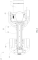
- FIG. 1 is a schematic diagram showing an example photographing apparatus 100 consistent with the disclosure.
- the photographing apparatus 100 includes a photographing device C, a gimbal apparatus 20, and a supporting device 40.
- the photographing device C is configured to capture images or videos, and can include, but is not limited to, a camera, a video camera, or a mobile phone or tablet having a camera function.
- the supporting device 40 is connected to the gimbal apparatus 20 and configured to support the gimbal apparatus 20.
- the supporting device 40 can be a handheld supporting device that can be held by a user.
- the supporting device 40 can be a non-handheld supporting device arranged on, for example, an unmanned aerial vehicle (UAV), an unmanned vehicle, a driverless ship, or the like, for supporting the gimbal apparatus 20.
- UAV unmanned aerial vehicle
- unmanned vehicle unmanned vehicle
- driverless ship or the like
- the gimbal apparatus 20 is configured to carry the photographing device C, and can be configured to change a photographing angle of the photographing device C and compensate for the influence of vibrations on the photographing device C. As shown in FIG.1 , the gimbal apparatus 20 includes a load-stabilizing apparatus 22 and a gimbal 24.
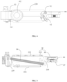
- FIG. 2 is a schematic diagram showing an example gimbal apparatus 20 consistent with the disclosure.
- FIG. 3 is a top view of the gimbal apparatus 20 consistent with the disclosure.
- the gimbal 24 can be a three-axis gimbal.
- the three-axis gimbal can adjust the angles of the photographing device C around a yaw axis, a roll axis, and a pitch axis.
- the gimbal 24 includes a first-axis driver 241, a first bracket 242, a second-axis driver 243, a second bracket 244, and a third-axis driver 245.
- the first bracket 242 is connected to the first-axis driver 241 and can be driven by the first-axis driver 241 to rotate about the first axis Z1.
- the second-axis driver 243 is fixedly arranged at an end of the first bracket 242 distal from the first-axis driver 241.
- the second bracket 244 is connected to the second-axis driver 243 and can be driven by the second-axis driver 223 to rotate about the second axis Z2.
- the third-axis driver 245 is fixedly arranged at an end of the second bracket 244 distal from the second-axis driver 243.
- the photographing device C is connected to the third-axis driver 245 and can be driven by the third-axis driver 245 to rotate about the third axis Z3.
- the first-axis driver 241, the second-axis driver 243, and the third-axis driver 245 can be, e.g., brushless motors.
- the gimbal 24 can be a single-axis gimbal, a two-axis gimbal, or any other type of gimbal.
- the gimbal 24 can also include a sensor (not shown in FIG. 2 ) and a processor (not shown in FIG. 2 ).
- the sensor can be configured to sense an attitude of the gimbal 24 and/or an attitude of the photographing device C.
- the sensor may include an inertial measurement unit (IMU) for measuring the attitudes, such as an angular rate of each rotating axis of the gimbal 24, an accelerating rate of the photographing device C, and/or the like.
- the sensor may include an angle sensor, such as a photoelectric encoder, for measuring the rotation angle at each rotating axis of the gimbal 24.
- IMU inertial measurement unit
- the sensor may include an angle sensor, such as a photoelectric encoder, for measuring the rotation angle at each rotating axis of the gimbal 24.
- the type of the sensor is not limited herein.
- the processor can be configured to control at least one of the first-axis driver 241, the second-axis driver 243, and the third-axis driver 245, according to the attitude information obtained by the sensor, to eliminate the effect of the vibration of the photographing apparatus 100 in the axial direction on the photographing device C. That is, the gimbal has a stabilizing function in the axial direction and can be regarded as a stabilizing mechanism in the axial direction.
- the processor can control at least one of the first-axis driver 241, the second-axis driver 243, and the third-axis driver 245 to rotate in a direction opposite to the vibration direction of the photographing apparatus 100 to eliminate the effect of the vibration of the photographing apparatus 100 in the axial direction on the photographing device C.
- the processor can be further configured to control at least one of the first-axis driver 241, the second-axis driver 243, and the third-axis driver 245 in response to user's instruction information to achieve a photographing at an angle or direction desired by the user.
- the gimbal 24 further includes a joint component 240 fixedly connected to the first-axis driver 241.
- the joint component 240 can be connected to the load-stabilizing apparatus 22.
- the joint component 240 can further include an electrical connecting portion (not shown in FIG. 2 ).
- the electrical connecting portion can electrically couple the photographing device C, and/or the first-axis driver 241, the second-axis driver 243, and the third-axis driver 245 to the other electronic components (e.g., power supply, control panel, processor, or the like, arranged at other locations).
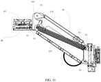
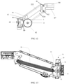
- FIG. 4 is a side view of the load-stabilizing apparatus 22 consistent with the disclosure.
- FIG. 5 is a cross-sectional view of the load-stabilizing apparatus 22 consistent with the disclosure.
- FIG. 6 is an exploded perspective view of the load-stabilizing apparatus 22 consistent with the disclosure.
- the load-stabilizing apparatus 22 includes a stabilizing motor 62, a load-connecting member 80, and a connecting assembly 220.
- the load-connecting member 80 is configured to carry a load.
- the load-connecting member 80 can also be referred to as a load connector or a load bearer.
- the load can include a photographing device, such as a camera, a video camera, a mobile phone or tablet having a camera function, or the like, and/or a gimbal.
- the connecting assembly 220 is connected to the load-connecting member 80.
- the load-connecting member 80 is connected to the joint component 240. For example, as shown in FIGs.
- an interface 87 is provided at an end of the load-connecting member 80 and configured to be connected to the load, e.g., the gimbal 24 in the embodiments of the disclosure.
- the joint component 240 can be inserted into the interface 87 to realize the connection between the load-connecting member 80 and the joint component 240.
- the joint component 240 can be engaged, threaded, or interference fit with the load-connecting member 80.
- the stabilizing motor 62 is drivingly connected to the connecting assembly 220 and configured to drive the connecting assembly 220 to move, such that the connecting assembly 220 drives the load-connecting member 80 to move translationally.
- An angle between the load-connecting member 80 and the connecting assembly 220 is configured to gradually change when the connecting assembly 220 moves. It can be appreciated that the stabilizing motor 62 can be any type of motor.
- the load-stabilizing apparatus 22 can utilize the stabilizing motor 62 to drive the gimbal 24 and the photographing device C arranged at the gimbal 24 to move in a direction opposite to a vibration of the photographing device C in the vertical direction (the gravity direction), such that the vibration of the photographing device C in the vertical direction can be compensated for.
- the image jitter caused by the vibration of the photographing device C during image shooting can be improved.
- the connecting assembly 220 can transmit the movement of the stabilizing motor 62 to the load-connecting member 80 to cause the load-connecting member 80 to move in the vertical direction.
- the connection assembly 220 can include, but is not limited to, a rack and pinion mechanism, a slider crank mechanism, a ball screw, and/or the like.
- the connection assembly 220 can include a deformation mechanism.
- the stabilizing motor 62 can drive the deformation mechanism to deform.
- the deformation mechanism can include a parallelogram mechanism 223.
- the parallelogram mechanism 223 includes a first connecting arm 222, a second connecting arm 224, and a first supporting arm 226 rotatably connected to the first connecting arm 222 and the second connecting arm 224.
- the first connecting arm 222 and the second connecting arm 224 are parallel to each other.
- the load-connecting member 80 is connected to the first supporting arm 226.
- the connecting assembly 223 and the load-connecting member 80 collectively form a load-supporting assembly 30.
- the stabilizing motor 62 is drivingly connected to at least one of the first connecting arm 222 or the second connecting arm 224.
- the load-stabilizing apparatus 22 further includes a base 60.
- the base 60 can also be referred to as a supporting member.
- the parallelogram mechanism 223 further includes a second supporting arm 228.
- the second supporting arm 228 is arranged opposite to the first supporting arm 226 and fixedly connected to the base 60.
- An end of the first connecting arm 222 and an end of the second connecting arm 224 are connected to the first supporting arm 226, and another end of the first connecting arm 222 and another end of the second connecting arm 224 are rotatably connected to the second supporting arm 228.
- the second supporting arm 228 can be considered as a relatively fixed, i.e., immovable, component, and the first connecting arm 222, the second connecting arm 224, and the first supporting arm 226 are moving about the second supporting arm 228.
- the parallelogram mechanism 223 can be regarded as a four-bar linkage mechanism, and the first connecting arm 222, the second connecting arm 224, the first supporting arm 226, and the second supporting arm 228 can be regarded as four arms of the four-bar linkage mechanism.
- the first supporting arm 226 and the load-connecting member 80 are one-piece molded.
- “One-piece molded" or “one-piece molding” means that two components are integrally formed with each other.
- the first supporting arm 226 can be integrally formed with the load-connecting member 80.
- the first supporting arm 226 can be fixedly attached to the load connection portion 80 in a detachable manner or in a non-detachable manner.
- the second supporting arm 228 can be arranged at or attached to the base 60.
- the second supporting arm 228 and the base 60 are one-piece molded.
- the second supporting arm 228 can also be fixedly attached to the base 60 in a detachable manner or in a non-detachable manner.
- the first connecting arm 222 includes two first protruding portions 2223 extending from opposite edges of the first connecting arm 222 toward the second connecting arm 224.
- the second connecting arm 224 includes two second protruding portions 2243 extending from opposite edges of the second connecting arm 224 toward the first connecting arm 222. As such, the first connecting arm 222 and the second connecting arm 224 form a cavity.
- each first protruding portion 2223 includes two ear portions extending from opposite ends of the first protruding portion 2223 along a length direction of the first protruding portion 2223.
- Each second protruding portion 2243 includes two ear portions extending from opposite ends of the second protruding portion 2243 along a length direction of the second protruding portion 2243.
- the first supporting arm 226 includes two side portions opposite to each other. Each of the two side portions has an L-shape-like structure and includes a first arm 226-1 and a second arm 226-2. During operation, the first arm 226-1 can be maintained approximately parallel to the ground. The second arm 226-2 is approximately vertical to the first arm 226-1. In some embodiments, the first arm 226-1 and the second arm 226-2 can be one-piece molded.
- the load-connecting member 80 is connected to the first arm 226-1. In some embodiments, a distance between the two side portions is greater than a width of the first connecting arm 222 and a width of the second connecting arm 224. A width of the second supporting arm 228 is smaller than the width of the first connecting arm 222 and the width of the second connecting arm 224. The width of the first connecting arm 222 is different from the width of the second connecting arm 224.
- the two ends of the first connecting arm 222 are respectively hinged with the first supporting arm 226 and the second supporting arm 228.
- the ear portion of each first protruding portion 2223 proximal to the first supporting arm 226 is hinged with the first arm 226-1 of the corresponding side portion arranged near a first end of the corresponding side portion.
- the first end of the side portion is an end of the first arm 226-1 distal from the load-connecting member 80.
- the hinge point of the ear portion of each first protruding portion 2223 and the first supporting arm 226 is denoted as S1.
- each second protruding portion 2243 proximal to the first supporting arm 226 is hinged with the second arm 226-2 of the corresponding side portion arranged near a second end of the corresponding side portion.
- the second end of the side portion is an end of the second arm 226-2 distal from the first arm 226-1.
- the hinge point of the ear portion of each second protruding portion 2243 and the first supporting arm 226 is denoted as S2.
- the ear portions of the two first protruding portions 2223 proximal to the second supporting arm 228 are hinged with opposite sides of the second supporting arm 228 at positions near a first end of the second supporting arm 228.
- the first end of the second supporting arm 228 is an end of the second supporting arm 228 proximal to the ear portions of the two first protruding portions 2223.
- the hinge point of the ear portion of each first protruding portion 2223 and the second supporting arm 228 is denoted as S3.
- the ear portions of the two second protruding portions 2243 proximal to the second supporting arm 228 are hinged with the opposite sides of the second supporting arm 228 at positions near a second end of second supporting arm 228.
- the second end of the second supporting arm 228 is an end of the second supporting arm 228 proximal to the ear portions of the two second protruding portions 2243.
- the hinge point of the ear portion of each second protruding portion 2243 and the second supporting arm 228 is denoted as S4.
- a line connecting the hinge points S1 and S3 can be denoted as S1S3, and a line connecting the hinge points S2 and S4 can be denoted as S2S4.
- the line S1S3 and the line S2S4 can be parallel to each other and have the same length. That is, the first connecting arm 222, the second connecting arm 224, the first supporting arm 226, and the second supporting arm 228 can form a parallelogram structure.
- An angle between the adjacent arms e.g., the angle between the first connecting arm 222 and the first supporting arm 226, or the angle between the second connecting arm 224 and the first supporting arm 226) can vary.
- the opposite arms are always approximately parallel to each other (e.g., the first connecting arm 222 is approximately parallel to the second connecting arm 224 and the first supporting arm 226 is approximately parallel to the second supporting arm 228).
- the first arm 226-1 of the first supporting arm 226 can be maintained approximately parallel to the ground and the second arm 226-2 of the first supporting arm 226 can be maintained approximately vertical to the ground.
- the first connecting arm 222, the second connecting arm 224, the first supporting arm 226, and the second supporting arm 228 can be regarded as four arms of the four-bar linkage mechanism as noted above. That is, the lines S1S3, S2S4, S1S2, and S3S4 of the adjacent hinge points can represent the four arms of the four-bar linkage mechanism.
- the stabilizing motor 62 can be rotatably connected to at least one of the first connecting arm 222 or the second connecting arm 224 and drive the first connecting arm 222 and/or the second connecting arm 224 to rotate clockwise or counterclockwise relative to the second supporting arm 228, thereby causing the first supporting arm 226 to rise or fall.
- the stabilizing motor 62 is arranged at a side of the base 60.
- the load-stabilizing apparatus 22 further includes a force-transferring member 66 movably connected to the parallelogram mechanism 223 and the stabilizing motor 62, such that the stabilizing motor 62 can drive the parallelogram mechanism 223 to deform via the force-transferring member 66.
- the force-transferring member 66 can be rotatably connected to the parallelogram mechanism 223 and the stabilizing motor 62.
- the force-transferring member 66 and the stabilizing motor 62 can form a slider-crank mechanism.
- a hinge (not shown in FIG. 6 ) can be arranged at a rotor of the stabilizing motor 62 and the force-transferring member 66 can be rotatably connected to the stabilizing motor 62 via the hinge.
- the hinge can be spaced apart from a rotating shaft of the stabilizing motor 62.
- the rotor of the stabilizing motor 62 and the hinge can be one-piece molded.
- the stabilizing motor 62 is a first stabilizing motor and the load-stabilizing apparatus 22 further includes a second stabilizing motor.
- the first stabilizing motor and the second stabilizing motor are symmetrically arranged at opposite sides of the parallelogram mechanism 223, and can be arranged to be co-axial to each other.
- the first stabilizing motor and the second stabilizing motor are symmetrically arranged at opposite sides of the base 60.
- One or both of the first stabilizing motor and the second stabilizing motor can be connected to at least one of the first connecting arm 222 or the second connecting arm 224.
- the first stabilizing motor and the second stabilizing motor are connected to the second connecting arm 224.
- the first stabilizing motor can rotate synchronously with the second stabilizing motor, such that the first stabilizing motor and the second stabilizing motor can together drive the parallelogram mechanism 223 to deform.
- the force-transferring member 66 is a first force-transferring member rotatably connected to the first stabilizing motor and the parallelogram mechanism 223.
- the load-stabilizing apparatus 22 further includes a second force-transferring member rotatably connected to the second stabilizing motor and the parallelogram mechanism 223.
- the first force-transferring member and the second force-transferring member are arranged symmetrically at opposite sides of the parallelogram mechanism 223. For example, as shown in FIG. 6 , the first force-transferring member and the second force-transferring member are arranged at opposite outer sides of the two second protruding portion 2243 of the second connecting arm 224 and proximal to the base 60.
- the base 60 includes a base body 10 connected to the parallelogram mechanism 223, and a base extending arm 61 extending outward from an end of the base body 10.
- the second supporting arm 228 is fixedly connected to the base body 10.
- the stabilizing motor 62 is arranged at the base extending arm 61.
- the base extending arm 61 is a first base extending arm and the base further includes a second base extending arm.
- the second stabilizing motor is arranged at the second base extending arm extending outward from another end of the base body 10.
- the first base extending arm and the second base extending arm are respectively bent and extended from two ends of the base body 10 toward a side of the base body 10 proximal to the parallelogram mechanism 223, such that the base 60 has a U-shape-like structure.
- the base body 10, the first base extending arm, and the second extending arm can be one-piece molded.
- FIG. 7 is a perspective view of the load-stabilizing apparatus 22 consistent with the disclosure.
- FIG. 8 is another perspective view of the load-stabilizing apparatus 22 consistent with the disclosure.
- each of the base extending arms 61 includes a receiving channel 61-1 for receiving an electrical signal transmission wire of the corresponding stabilizing motor 62.
- the first base extending arm includes the receiving channel 61-1 for receiving the electrical signal transmission wire of the first stabilizing motor
- the second base extending arm includes the receiving channel 61-1 for receiving the electrical signal transmission wire of the second stabilizing motor.
- Each receiving channel 61-1 can be arranged inside the corresponding base extending arms 61.
- the base body 10 includes a receiving space 10-1 for receiving a control circuit 1000.
- the control circuit 1000 can be configured to control the two stabilizing motors 62 and/or transmit a power signal to the two stabilizing motors 62 via the electrical signal transmission wires of the two stabilizing motors 62.
- the electrical signal transmission wires of the two stabilizing motors 62 can also transmit rotation angle information of the two stabilizing motors 62.
- the base body 10 further includes a through hole 10-2 in communication with the receiving space 10-1.
- An electrical signal transmission wire of a motion sensor can pass through the through hole 10-2.
- the motion sensor can include at least one of an angle sensor or an Inertial Measurement Unit (IMU).
- the motion sensor can include at least one of a sensor for measuring motion data of the load-connecting member 80 or a sensor for measuring a rotation angle of the parallelogram mechanism 223.
- the rotation angle of the parallelogram mechanism 223 can be an angle of the parallelogram mechanism 223 rotating relative to the base 60.
- the load-connecting member 80 includes a receiving recess 80-1 for receiving a motion-detecting circuit.
- the motion-detecting circuit can be mounted at the load-connecting member 80 and configured to measure motion of the load-connecting member 80.
- the motion-detecting circuit can include a motion sensor configured to obtain the motion data of the load-connecting member 80.
- the motion sensor can include, for example, an IMU.
- a detection circuit can be mounted at the parallelogram mechanism 223 and configured to measure a motion of the parallelogram mechanism 223.
- the detection circuit can include an angle sensor configured to measure the rotation angle of the parallelogram mechanism 223.
- the angle sensor can be configured to measure a rotation angle of at least one of the first connecting arm 222 or the second connecting arm 224.
- the interface 87 can include a quick-release connector (not shown in FIGs. 7 and 8 ).
- the load-connecting member 80 can be detachably connected to the load via the quick-release connector.
- the interface 87 can include an electrical signal interface.
- the electrical signal interface can be configured to transmit an input electrical signal to the load and/or receive an output electrical signal outputted by the load.
- the input electrical signal can include at least one of a power signal or a load control signal.
- the load control signal can be the signal to control a shooting operation of the load.
- the output electrical signal can include sensing data collected by the load.
- the sensing data collected by the load can be the image or video captured by the load.
- the electrical signal interface can also transmit an input signal to the gimbal 24 and/or receive an output signal outputted by the gimbal 24.
- the input signal can include the power signal and/or a control command to control a movement of the gimbal 24.
- the output signal can include, e.g., rotation angle information of the gimbal 24.
- the parallelogram mechanism 223 includes at least one threading channel 223-1.
- An electrical signal transmission wire communicationally connected to the electrical signal interface can be arranged in the at least one threading channel 223-1.
- an electrical signal transmission wire electrically connected to the motion-detecting circuit can be arranged in the at least one threading channel 223-1.
- the at least one threading channel 223-1 can be arranged at the first connecting arm 222, at the second connecting arm 224, or between the first connecting arm 222 and the second connecting arm 224.
- the load-stabilizing apparatus 22 further includes an elastic member 50.
- the elastic member 50 is configured to provide an elastic force to the connecting assembly 220.
- a vertical component of the elastic force generated by the elastic member 50 can be used to balance a weight of the photographing device C, a weight of the gimbal 24, and/or a weight of the load-stabilizing apparatus 22.
- the elastic member 50 is arranged inside the cavity of connecting assembly 220, which is formed by the first connecting arm 222 and the second connecting arm 224.
- the elastic member 50 can include a spring (e.g., a coil spring).
- the elastic member 50 can be mounted at the load-stabilizing apparatus 22 in various manners. For example, an end 52 (see, e.g., FIGs. 2 , 10 , 11 , 14 , and 15 ) of the elastic member 50 can be mounted at the second supporting arm 228 or the base body 10, and another end 54 (see, e.g., FIGs.
- the elastic member 50 can be mounted at the first supporting arm 226, the first connecting arm 222, or the second connecting arm 224, as long as the elastic member 50 can provide the elastic force to balance or partially balance the weight of the load (e.g., the photographing device C, the gimbal 24, or the like).
- a position of the end 54 of the elastic member 50 can be adjusted to adjust the elastic direction of the elastic member 50.
- the load-stabilizing apparatus 22 further includes a switching assembly 41 arranged at the deformation mechanism.
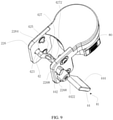
- FIG. 9 is a perspective view of the switching assembly 41 consistent with the disclosure.
- the switching assembly 41 can be rotatably connected to the deformation mechanism and configured to adjust an elastic direction of the elastic member 50. As shown in FIG. 9 , the switching assembly 41 includes a switching member 42, a switching handle 44, and an engaging member 442.
- the switching member 42 is connected to the end 54 of the elastic member 50.
- the end 54 of the elastic member 50 can also be referred to as an active end.
- the switching member 42 includes a crankshaft.
- the crankshaft includes two shaft portions 423, an eccentric portion 427, and two connecting portions 425.
- the two shaft portions 423 are arranged at two opposite sides of the crankshaft.
- the eccentric portion 427 is arranged at a middle part of the crankshaft and deviates from a rotation axis of the two shaft portions 423.
- the two connecting portions 425 extend from the two shaft portions 423 and are connected between the two shaft portions 423 and the eccentric portion 427.
- the first supporting arm 226 further includes two shaft holes 2264 at the two side portions of the first supporting arm 226, respectively.
- the two shaft portions 423 can be rotatably mounted at the first supporting arm 226 through the shaft holes 2264.
- a line connecting the two shaft holes 2264 is a rotation axis of the crankshaft.
- the eccentric portion 427 is arranged at a distance from the rotation axis of the crankshaft, and the distance is determined by a length of the two connecting portions 425.
- the eccentric portion 427 includes a notch 4272 and the end 54 of the elastic member 50 proximal to the first supporting arm 226 is hooked to the notch 4272.
- a rotatable connection between the elastic member 50 and the eccentric portion 427 can be achieved by hooking a hook (not shown in FIG. 9 ) of the end 54 of the elastic member 50 in the notch 4272.
- the position of the end 54 of the elastic member 50 can be changed with a rotation of the eccentric portion 427.
- the elastic direction and elastic strength of the elastic member 50 can be changed and the end 54 can be rotated relative to the notch 4272.
- the switching handle 44 is fixedly connected to the switching member 42 and configured to receive an external force to drive the switching member 42 to rotate to adjust a position of the end 54 of the elastic member 50.
- the switching handle 44 includes a rotating portion 444.
- a user can apply a force to the rotating portion 444 to control the switching member 42 to rotate.
- the rotating portion 444 can have a plate shape that is convenient for the user to rotate.
- the engaging member 442 is connected to the switching handle 44 and the switching member 42.
- the engaging member 442 has a cylindrical shape and includes a shaft mounting hole 4422.
- the shaft portion 423 of the crankshaft distal from the switching handle 44 can penetrate through the shaft hole 2264 and another shaft portion 423 proximal to the switching handle 44 can be inserted into the shaft mounting hole 4422.
- the crankshaft can be driven to rotate by the rotating portion 444, thereby driving the end 54 of the elastic member 50 to switch among different positions.
- the eccentric portion 427 and the end 54 of the elastic member 50 can stay at any position during the rotation of the crankshaft.
- the rotating portion 444 can rotate clockwise or counterclockwise within a certain range of angles, and can stably stay and remain at two limiting positions (one of the two limiting positions corresponds to a limiting position of clockwise rotation, and another limiting position corresponds to a limiting position of counterclockwise rotation).
- the deformation mechanism further includes two stopper members (or simply “stoppers") 2268.
- the two stopper members 2268 are arranged at an upper position and a lower position of an outer side of one of the two side portions of the first supporting arm 226 proximal to the switching handle 44.
- the stopper member 2268 arranged at the upper position can also be referred to as a first stopper member, and another stopper member 2268 arranged at the lower position can also be referred to as a second stopper member.
- the two stopper members 2268 are configured to hold the rotating portion 444 at a position corresponding to a normal position of the end 54 of the elastic member 50 or a position corresponding to an inverse position of the end 54 of the elastic member 50.
- the rotating portion 444 can be held to the two limiting positions because of the blocking of the stopper members 2268 and the elastic force of the elastic member 50.
- FIG. 10 is a cross-sectional view of the load-stabilizing apparatus 22 in a first stabilization mode consistent with the disclosure.
- FIG. 11 is a cross-sectional view of the load-stabilizing apparatus 22 in a second stabilization mode consistent with the disclosure.
- FIG. 12 is a side view of the load-stabilizing apparatus 22 in the first stabilization mode consistent with the disclosure.
- the normal position of the end 54 of the elastic member 50 is a position closer to the second connecting arm 224 than the first connecting arm 222 and can also be referred to as a first active end position.
- the inverse position of the end 54 of the elastic member 50 is a position closer to the first connecting arm 222 than the second connecting arm 224 and can also be referred to as a second active end position.
- the elastic direction of the elastic member 50 is in a first elastic direction, and a first side of the engaging member 442 abuts the first stop member under the elastic force in the first elastic direction.
- the first side of the engaging member 442 is a side of the engaging member 442 proximal to the first stop member.
- the switching member 42 adjusts the end 54 from the first active end position to the second active end position, the elastic direction of the elastic member 50 is in a second elastic direction, and a second side of the engaging member 442 abuts the second stop member under the elastic force in the second elastic direction.
- the second side of the engaging member 442 is a side of the engaging member 442 proximal to the second stop member.
- the load-stabilizing apparatus 22 can have the first stabilization mode and the second stabilization mode corresponding to the first elastic direction and the second elastic direction of the elastic member 50.
- An attitude of the load-stabilizing apparatus 22 in the second stabilization mode turns 180 degree in the vertical direction (i.e., upside-down) as compared to the attitude of the load-stabilizing apparatus 22 in the first stabilization mode.
- an orientation of the interface 87 of the load-connecting member 80 in the first stabilization mode can be different from the orientation of the interface 87 in the second stabilization mode, such that a mounting attitude of the load carried by the load-connecting member in the first stabilization mode can be different from the mounting attitude in the second stabilization mode.
- the orientation of the interface 87 of the load-connecting member 80 in the first stabilization mode can be opposite to the orientation of the interface 87 in the second stabilization mode, such that the mounting attitude in the first stabilization mode can be opposite to the mounting attitude in the second stabilization mode.
- the interface 87 faces downward and the load carried by the load-connecting member 80 is in a normal attitude, e.g., an upright mounting attitude.
- the interface 87 faces upward and the load carried by the load-connecting member 80 is in an inverse attitude, e.g., an upside-down mounting attitude.
- the deformation mechanism can be deformable and can have a plurality of deformation states.
- the plurality of deformation states can include a first stabilization state and a second stabilization state.
- the load-stabilizing apparatus 22 is in the first stabilization mode.
- the load-stabilizing apparatus 22 is in the second stabilization mode.
- a relative position of the first connecting arm 222 with respect to the second connecting arm 224 in the first stabilization state is different from the relative position in the second stabilization state.
- the relative position of the first connecting arm 222 with respect to the second connecting arm 224 in the first stabilization state can be opposite to the relative position in the second stabilization state.
- the first connecting arm 222 in the first stabilization state, is above the second connecting arm 224.
- the first connecting arm 222 in the second stabilization state, is below the second connecting arm 224.
- a length of a diagonal of the parallelogram mechanism 223 in the first stabilization state is different from the length of the diagonal of the parallelogram mechanism 223 in the second stabilization state.
- the diagonal of the parallelogram mechanism 223 can be a line connecting the hinge points S1 and S4, which can be denoted as S1S4 and also referred to as a first diagonal.
- a second diagonal of the parallelogram mechanism 223 can be a line connecting the hinge points S2 and S3, which can be denoted as S2S3.
- the second diagonal S2S3 intersects the first diagonal S1S4.
- the length of the first diagonal S1S4 in the first stabilization mode, can be greater than a length of the second diagonal S2S3 of the parallelogram mechanism 223.
- the length of the first diagonal S1S4 in the second stabilization mode, can be shorter than the length of the second diagonal S2S3.
- the positions of the hinge points S1, S2, S3, and S4 are also shown in FIG. 12 .
- one or more vertex angles of the parallelogram mechanism 223 in the first stabilization mode are different from the one or more vertex angles of the parallelogram mechanism 223 in the second stabilization mode.
- a first vertex angle of the parallelogram mechanism 223 can be an angle between the line S1S3 and the line S1S2 and can be denoted as angle S2S1S3.
- a second vertex angle of parallelogram mechanism 223 can be an angle between the line S2S4 and the line S1S2, and can be denoted as angle S1S2S4.
- the second vertex angle S1S2S4 neighbors the first vertex angle S2S1S3.
- the first vertex angle S2S1S3 is smaller than the second vertex angle S1S2S4 of the parallelogram mechanism 223.
- the first vertex angle S2S1S3 is greater than the second vertex angle S1S2S4.
- the end 54 of the elastic member 50 can be switched to the position adjacent to the second connecting arm 224 by rotating the rotating portion 444.
- the change in the position of the end 54 of the elastic member 50 can cause the elastic direction of the elastic force to be changed to the first elastic direction.
- the deformation mechanism can swing upward relative to the base 60. The deformation mechanism can then switch to the first stabilizing state and the load-stabilizing apparatus 22 can be in the first stabilizing mode.
- the end 54 of the elastic member 50 can be switched to the position adjacent to the first connecting arm 222 by rotating the rotating portion 444.
- the change in the position of the end 54 of the elastic member 50 can cause the elastic direction of the elastic force to be changed to the second elastic direction.
- the deformation mechanism can swing downward relative to the base 60. The deformation mechanism can then switch to the second stabilizing state and the load-stabilizing apparatus 22 can be in the second stabilizing mode.
- the rotating portion 444 for manual operation by a user can be omitted, and an automatic driving device (e.g., a switching motor) may be used.
- the switching motor can be a brushless motor.
- a sensor can be arranged at the load-connecting member 80, the connecting assembly 220, the base 60, or the like, and configured to sense the attitude of the load-stabilizing apparatus 22. If the load-stabilizing apparatus 22 is determined to be in the first stabilizing mode, a process can control the switching motor to switch the position of the end 54 of the elastic member 50 to the first active end position. If the load-stabilizing apparatus 22 is determined to be in the second stabilizing mode, a process can control the switching motor to switch the position of the end 54 of the elastic member 50 to the second active end position.
- the elastic force can include a pulling force.
- the deformation mechanism When the deformation mechanism is under the pulling force in a first pulling direction, the deformation mechanism is in the first stabilization state.
- the switching assembly 41 adjusts a pulling direction of the elastic member 50 from the first pulling direction to a second pulling direction, the deformation mechanism can be deformed to be in the second stabilization state by the pulling force in the second pulling direction.
- the elastic force can also include a compression force. When the switching assembly 41 adjusts a compressive direction of the elastic member 50 from the first compressive direction to a second compressive direction, the deformation mechanism can be deformed to be in the second stabilization state by the compression force in the second compressive direction.
- FIGs. 13 and 14 are schematic diagrams showing the load-stabilizing apparatus 22 carrying loads with different weights.
- the load-stabilizing apparatus 22 further includes an adjustment member 31.
- the adjustment member 31 is arranged at the second supporting arm 228 and configured to adjust a degree of deformation of the elastic member 50.
- the elastic member 50 includes a spring
- the degree of deformation of the elastic member 50 can include a deformation length of the spring.
- the elastic force of the elastic member 50 can be adjusted by adjusting the degree of deformation of the elastic member 50.
- the adjustment member 31 can adjust the elastic force of the elastic member 50 (e.g., a component of the elastic force in the vertical direction) via adjusting the degree of deformation of the elastic member 50, such that loads carried by the load-stabilizing apparatus 22 with different weights can be balanced.
- the elastic force of the elastic member 50 can be maintained unchanged, the component of the elastic force in the vertical direction can be changed by adjusting the direction of the elastic force provided by the elastic member 50, such that the loads with different weights can be balanced.
- the load with certain weight can be balanced by simultaneously adjusting a magnitude and the direction of the elastic force of the elastic member 50.
- the end 52 of the elastic member 50 is connected to the adjustment member 31.
- the adjustment member 31 can adjust the degree of deformation of the elastic member 50 by adjusting a mounting position of the end 52 of the elastic member 50 under an external force.
- the elastic member 50 can drive the load-supporting assembly 30 to rotate relative to the base 60 to adjust the position of the load carried by the load-connecting member 80 in a vertical movement stroke.
- the adjustment member 31 can be configured to adjust the mounting position of the end 52 on the adjustment member 31 toward a first direction under the external force to increase the degree of deformation of the elastic member 50.
- the first direction can be an upward direction or a downward direction.
- the elastic member 50 can be configured, in response to the adjustment member 31 being adjusted to increase the degree of deformation of the elastic member 50, to drive the load-supporting assembly 30 to rotate relative to the base 60 in a first rotation direction, such that the position of the load in the vertical direction can be adjusted upwards.
- the adjustment member 31 can be configured to adjust the mounting position of the end 52 on the adjustment member 31 toward a second direction under the external force to decrease the degree of deformation of the elastic member 50.
- the second direction can be opposite to the first direction.
- the elastic member 50 can be configured, in response to the adjustment member 31 being adjusted to decrease the degree of deformation of the elastic member 50, to drive the load-supporting assembly 30 to rotate relative to the base 60 in a second rotation direction, such that the position of the load in the vertical direction can be adjusted downwards.
- the second rotation direction can be opposite to the first rotation direction.
- the adjustment member 31 can balance the loads with different weights by adjusting a height of the end 52 of the elastic member 50 relative to the second supporting arm 228.
- the adjustment member 31 includes an adjusting lever 34, an adjusting sleeve 36 sleeved on the adjusting lever 34, and an operating portion 32 connected to the adjusting lever.
- the adjusting lever 34 can be rotatably arranged at the second supporting arm 228 or the base body 10.
- a length direction of the adjusting lever 34 is approximately parallel to a longitudinal direction of the second supporting arm 228.
- the adjusting lever 34 can be arranged in the vertical direction.
- the adjusting lever 34 can have a cylindrical shape and have an external thread on a cylindrical surface.
- the adjusting lever 34 can include a lead screw.
- a recess 2282 (see, e.g., FIG. 6 ) can be provided at a side of the second supporting arm 228 facing the first supporting arm 226.
- the adjusting level 34 can be arranged in the recess 2282, such that the adjusting sleeve 36 can extend into the recess 2282 and be connected to the adjusting lever 34.
- the adjusting sleeve 36 can include a sleeve portion having an internal thread, such as a lead nut.
- the internal thread of the adjusting portion can be engaged with the external thread of the adjusting level 34, such that a threaded connection of the adjusting sleeve 36 with the adjusting level 34 can be achieved. Therefore, when the adjusting lever 34 is rotated, the adjusting sleeve 36 can be vertically moved upward and downward with respect to the adjusting lever 34 and the second supporting arm 228.
- the adjusting sleeve 36 includes a mounting portion 365.
- the end 52 of the elastic member 50 can be rotatably connected to the mounting portion 365.
- a protruding component 362 can protrude from a side of the sleeve portion.
- the protruding component 362 can have the mounting portion 365 having a cylindrical shape.
- the end 52 of the elastic member 50 can be provided with a hook (not shown), and the hook can be rotatably sleeved on the mounting component 365.
- the operating portion 32 protrudes from a surface of the second supporting arm 228.
- the operating portion 32 allows the user to rotate the adjusting lever 34 directly or indirectly, so as to change a position of the adjusting sleeve 36 on the adjusting lever 34.
- the operating portion 32 can have an approximately truncated cone shape, and a peripheral side surface of the operating portion 32 can include a surface having a certain roughness, such that the user can more easily operate the adjusting lever 34 to rotate. It can be appreciated that the operating portion 32 can also include an elliptical platform or a polygonal prismatic platform.
- a connecting position of the adjusting sleeve 36 and the adjusting lever 34 can be adjusted by rotating the adjusting lever 34. That is, a connection height of the end 52 of the elastic member 50 with respect to the second supporting arm 228 can be adjusted.
- the elastic force of the elastic member 50 can be adjusted by adjusting the connection height of the end 52 of the elastic member 50 with respect to the second supporting arm 228. Therefore, the load-stabilizing apparatus 22 can adjust the elastic force of the elastic member 50 in accordance with the weight of the load.
- the load can be the photographing device C and the gimbal 24. In some embodiments, the load may only include the photographing device C or the gimbal 24.
- the load-stabilizing apparatus 22 further includes a position adjustment motor 38.
- the adjustment motor 38 can be configured to drive the adjusting lever 34 to rotate,thereby automatically adjusting the elastic force of the elastic member 50.
- the position adjustment motor 38 can be arranged at one end of the second supporting arm 228.
- the position adjustment motor 38 can be any type of motor.
- a sensor can be provided to obtain information related to the position of the load-connecting member 80.
- a processor can be arranged at the load-stabilizing apparatus 22, for example in the receiving space of the base body 10, at the receiving recess 80-1 of the load-connecting member 80, or the like.
- the processor can be configured to control the position adjustment motor 38, according to the information, to rotate to actively adjust the force provided by the elastic member 50 to the load-supporting assembly 30 to adapt to the weight of the load.
- the force provided by the elastic member 50 can be adjusted to cause an angle of the connecting assembly 220 relative to the base 60 to remain at a preset angle, such as 90 degrees.
- the preset angle can keep the first connecting arm 222 and the second connecting arm 224 in, for example, a horizontal or approximately horizontal direction, e.g., parallel or approximately parallel to the ground.
- the force provided by the elastic member 50 can be adjusted to cause the load to be in a preset position in a vertical motion trajectory.
- the sensor can include an angle sensor that can be used for assisting the processor in determining the amount and direction of the rotation of the position adjustment motor 38.
- the angle sensor is configured to detect the angle of the connecting assembly 220 relative to the base 60.
- the position adjustment motor 38 can be configured, in response to the angle sensor detecting that the angle of the connecting assembly 220 relative to the base 60 is greater than 90 degrees, to drive the adjusting lever 34 to rotate in a direction to move the adjusting sleeve 36 toward the one end of the second supporting arm 228, and in response to the angle sensor detecting that the angle of the connecting assembly 220 relative to the base 60 is smaller than 90 degrees, to rotate in another direction to move the adjusting sleeve 36 toward another end of the second supporting arm 228.
- the angle sensor can be configured to detect an angle formed between the second connecting arm 224 and the second supporting arm 228.
- the angle measured by the angle sensor will be less than 90 degrees, and the processor can determine that the load is light, and the adjustment sleeve 36 needs to be lowered. Adjustment is made to change the direction of the elastic force of the elastic member 50 and shorten the length of the elastic member 50.
- the processor will control the position adjustment motor 38 to rotate in a particular direction and with a particular amplitude, such that the second connecting arm 224 can be perpendicular to the second supporting arm 228.
- the angle measured by the angle sensor will be larger than 90 degrees, and the processor can determine that the load is heavy, and the adjustment sleeve 36 needs to be raised. Adjustment is made to change the direction of the elastic force of the elastic member 50 and lengthen the length of the elastic member 50.
- the processor will control the position adjustment motor 38 to rotate in a particular direction and with a particular amplitude, such that the second connecting arm 224 can be perpendicular to the second supporting arm 228.
- whether the elastic member 50 matches the load can be determined by whether the second connecting arm 224 and the second supporting arm 228 are perpendicular (i.e., whether the angle measured by the angle sensor is 90 degrees). In some other embodiments, other angles may be used as a reference to determine whether the elastic member 50 matches the load, which is note limited herein.
- a plurality of mounting positions of the end 52 of the elastic member 50 connected to the adjustment assembly corresponding to a plurality of different weights of the load can be predetermined.
- the processor can be configured to recognize the load and automatically drive a motor to adjust the end 52 of the elastic member 50 to the corresponding predetermined mounting position.
- the load can send an identification number (ID) of the load to the processor, such that the processor can recognize the load according to the ID.
- ID identification number
- the position of the adjustment assembly and the position of the switching assembly 41 can be interchangeable. That is, in some other embodiments, the adjustment assembly can be arranged at the first supporting arm 226 and the switching assembly 41 can be arranged at the second supporting arm 228. As such, the position of the end 52 of the elastic member 50 can be adjusted by the switching assembly 41, and the position of the end 54 of the elastic member 50 can be adjusted by the adjustment assembly.
- the connecting assembly 220 can include a slider-crank mechanism.
- a hinging point of the force-transferring member 66 and the stabilizing motor 62 is denoted as S.
- the rotating center of the stabilizing motor 62 is denoted as R.
- the force-transferring member 66 can operate as a slider in the slider-crank mechanism.
- the line connecting the hinging point S and the rotating center R of the stabilizing motor 62 can be denoted as SR (non-physical structure) and regarded as the crank of the slider-crank mechanism.
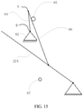
- FIG. 15 is a schematic diagram showing a working process of the slider-crank mechanism consistent with the disclosure.
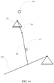
- FIG. 16 is another schematic diagram showing the working process of the slider-crank mechanism consistent with the disclosure.
- the slider-crank mechanism includes a crank 64 (line SR shown in FIG. 12 ) and a slider 66 (the force-transferring member 66 shown in, e.g., FIG. 12 ).
- a first end of the crank 64 is connected to the stabilizing motor 62 in a coaxially rotating manner (the crank 64 rotates about the rotating center R of the stabilizing motor 62), and a second end of the crank 64 is hinged to a first end of the slider 66.
- a second end of the slider 66 is hinged to the second connecting arm 224 (shown in FIGs. 15 and 16 as an example) or the first connecting arm 222.
- the second connecting arm 224 can be rotatable relative to the second supporting arm 228.
- the stabilizing motor 62 can be fixed to the second supporting arm 228.
- the crank 64 is equivalent to the line SR.
- the second connecting arm 224 can be reciprocated up and down driven by the slider 66 and has a highest position and a lowest position.
- the crank 64 and the slider 66 are folded toward each other and hence at least partially overlap to form a first dead point.
- the crank 64 and the slider 66 extend in two opposite direction and hence are connected in a straight line to form a second dead point.
- there are two dead points i.e., a first dead point and a second dead point corresponding to the highest position and the lowest position, respectively.
- a force transmitted by the second connecting arm 224 and the slider 66 to the crank 64 does not produce a moment that can cause the crank 64 to rotate.
- the load-stabilizing apparatus 22 further includes a first blocking member 65 and a second blocking member 67.
- a blocking member can also be referred to as a "block.”
- the first blocking member 65 is arranged at an outer side of the first protruding portion 2223 of the first connecting arm 222
- the second blocking member 67 is arranged at an outer side of the second protruding portion 2243 of the second connecting arm 224.
- the first blocking member 65 can be arranged at the second connecting arm 224 and the second blocking member 67 can be arranged at the first connecting arm 222.
- the first blocking member 65 is configured to block the force-transferring member 66 when the stabilizing motor 62 drive the force-transferring member 66 to pass a first preset position
- the second blocking member 67 is configured to block the force-transferring member 66 when the stabilizing motor 62 drive the force-transferring member 66 to pass a second preset position.
- the first preset position can include one of the first dead end and the second dead end
- the second preset position can include another one of the first dead end and the second dead end.
- the first preset position can include the first dead end and the second preset position can include the second dead end.
- the elastic force of the elastic member 50 when the force-transferring member 66 is in the first preset position is smaller than the elastic force when the force-transferring member 66 is in a position other than the first preset position.
- the elastic force of the elastic member 50 when the force-transferring member 66 is in the second preset position is greater than the elastic force when the force-transferring member 66 is in a position other than the second preset position.
- the first blocking member 65 can be arranged at or proximal to a position corresponding to the highest position.
- the first blocking member 65 may be arranged at the first connecting arm 222.
- the stabilizing motor 62 drives the crank 64 to rotate clockwise
- the second connecting arm 224 can rotate clockwise and continuously rise.
- the crank 64 and the slider 66 are connected in a line (e.g., partially coincident with each other)
- the second connecting arm 224 will reach the highest position.
- the highest position corresponds to a clockwise limit position of the crank-slider mechanism. If continuing to rotate for a small amount in the clockwise direction, the slider 66 will contact the first blocking member 65.
- the second connecting arm 224 at the highest position has a tendency to move downward.
- the tendency of the second connecting arm 224 to move downward will translate into a tendency for the crank 64 and the slider 66 to rotate clockwise. Due to a blocking of the first blocking member 65, the crank 64 and the slider 66 cannot continue to rotate clockwise, such that the crank 64, the slider 66, the second connecting arm 224, and the like, can be stably fixed at the position of the first blocking member 65. Therefore, even if the stabilizing motor 62 is de-energized, the state of the slider 66 and the load-stabilizing apparatus 22 can be locked.
- the second blocking member 67 can be arranged at or proximal to a position corresponding to the lowest position.
- the second blocking member 67 may be arranged at the second connecting arm 224.
- the stabilizing motor 62 drives the crank 64 to rotate counterclockwise
- the second connecting arm 224 can rotate counterclockwise and continuously fall.
- the crank 64 and the slider 66 are connected in a line without overlapping
- the second connecting arm 224 will reach the lowest position.
- the lowest position corresponds to a counterclockwise limit position of the crank-slider mechanism. If continuing to rotate for a small amount in the counterclockwise direction, the slider 66 will contact the second blocking member 67.
- the second connecting arm 224 at the lowest position has a tendency to move upward.
- the tendency of the second connecting arm 224 to move upward will translate into a tendency for the crank 64 and the slider 66 to rotate counterclockwise. Due to a blocking of the second blocking member 67, the crank 64 and the slider 66 cannot continue to rotate counterclockwise, such that the crank 64, the slider 66, the second connecting arm 224, and the like, can be stably fixed at the position of the second blocking member 67. Therefore, even if the stabilizing motor 62 is de-energized, the state of the slider 66 and the load-stabilizing apparatus 22 can be locked.
- the stabilization motor 62 can be configured to drive the crank 64 and the slider 66 to move between the highest position and the lowest position to realize an active stabilization function in the vertical direction.
- the user can manually or use the stabilizing motor 62 to rotate the second connecting arm 224 at a large angle, such that the slider 66 can abut and stabilize at the position of the first blocking member 65 or the second blocking member 67.
- crank-slider mechanism can cause the stabilization motor 62 to drive the second connecting arm 224 to swing back and forth, and can also provide the second connecting arm 224 with a locking function when the stabilization motor 62 is de-energized.
- only one blocking member is provided.
- only the first blocking member 65 or only the second blocking member 67 is provided.
- the blocking member can be arranged at the first connecting arm 223.
- the transmission member abuts the blocking member to block the load from moving in a specific vertical direction.
- the connecting assembly 220 can be rotated relative to the base 60 via the force-transferring member 66, and the load carried by the load-connecting member 80 can be moved in the vertical direction.
- the force-transferring member 66 abuts the blocking member to block the load from moving in the specific vertical direction.
Landscapes
- Engineering & Computer Science (AREA)
- General Engineering & Computer Science (AREA)
- Mechanical Engineering (AREA)
- Physics & Mathematics (AREA)
- General Physics & Mathematics (AREA)
- Accessories Of Cameras (AREA)
- Transmission Devices (AREA)
- Vibration Prevention Devices (AREA)
Description
- This application claims priority to PCT Application Nos.
PCT/CN2018/080373 PCT/CN2018/080366 PCT/CN2018/080372 PCT/CN2018/080367 PCT/CN2018/080371 PCT/CN2018/080368 PCT/CN2018/080370 PCT/CN2018/080369, all filed on March 23 2018 - The present disclosure relates to photographing technology and, more particularly, to a load-stabilizing apparatus, a gimbal apparatus, and a photographing apparatus.
- In order to achieve anti-vibration photography and increase the photographing stability to obtain higher-quality images during the use of a photographing device, the photographing device is generally mounted at a portable stabilization platform, such as a gimbal. The gimbal generally has the stabilizing function in a rotation direction of the photographing device. For example, a three-axis gimbal compensates for the vibration of the photographing device in the rotation direction of a pitch axis, the rotation direction of a yaw axis, and the rotation direction of a roll axis. However, the gimbal does not have a stabilizing function for a vibration of the photographing device in the direction of gravity.
-
WO 2015/055850 A2 discloses a stabiliser for a camera mount, the stabiliser including a vertical movement stabiliser assembly comprising a first pair of vertically spaced parallel arms, the parallel arms being co-terminus and having a proximal end and a distal end; a second pair of vertically spaced parallel arms, the parallel arms being co - terminus and having a proximal end and a distal end; and a connecting bracket pivotally coupled to the distal end of the first pair of arms and pivotally coupled to the proximal end of the second pair of arms, wherein the vertical movement stabiliser assembly has a first configuration in which the first pair of arms, the connecting bracket and the second pair of arms are all substantially aligned with each other; the connecting bracket extends from the distal end of the first pair of arms towards the proximal end of the first pair of arms; a portion of the first pair of arms is located adjacent to a portion of the second pair of arms with the bracket located therebetween; and the distal end of the second pair of arms extends beyond the distal end of the first pair of arms; wherein the vertical movement stabiliser has a second configuration in which the first pair of arms and the second pair of arms are parallel to each other, but out of alignment with each other; and wherein the first pair of arms includes a first biasing element, the second pair of arms includes a second biasing element, and the first and second biasing elements are arranged to bias the vertical movement stabiliser assembly to a rest configuration. -
EP 3 028 662 A1 - The invention is defined by
independent claim 1 defining a load-stabilizing apparatus. Embodiments of the claimed invention are defined by the dependent claims. In accordance with the disclosure, there is provided a load-stabilizing apparatus including a load-connecting member configured to carry a load, a parallelogram mechanism connected to the load-connecting member, and a stabilizing motor drivingly connected to the parallelogram mechanism. The stabilizing motor is configured to drive the parallelogram mechanism to deform, such that the parallelogram mechanism drives the load-connecting member to move. - Also in accordance with the disclosure, there is provided a load-stabilizing apparatus includes a load-connecting member configured to carry a load, a connecting assembly connected to the load-connecting member, and a stabilizing motor drivingly connected to the connecting assembly. The stabilizing motor is configured to drive the connecting assembly to move, such that the connecting assembly drives the load-connecting member to move translationally.
- Also in accordance with the disclosure, there is provided a load-stabilizing apparatus including a load-connecting member configured to carry a load, and a deformation mechanism connected to the load-connecting member. The deformation mechanism is deformable and has a plurality of deformation states including a first stabilization state and a second stabilization state. When the deformation mechanism is in the first stabilization state, the load-stabilizing apparatus is in a first stabilization mode, and when the deformation mechanism is in the second stabilization state, the load-stabilizing apparatus is in a second stabilization mode different from the first stabilization mode.
- Also in accordance with the disclosure, there is provided a load-stabilizing apparatus including a connecting assembly connected to a load-connecting member, an elastic member configured to provide an elastic force to the connecting assembly, and an adjustment assembly connected to the elastic member. The adjustment assembly is configured to adjust the elastic member to provide the elastic force in a plurality of directions including a first elastic direction and a second elastic direction different from the first elastic direction. When the elastic member provides the elastic force in the first elastic direction, the load-stabilizing apparatus is in a first stabilization mode, and when the elastic member provides the elastic force in the second elastic direction, the load-stabilizing apparatus is in a second stabilization mode different from the first stabilization mode.
- Also in accordance with the disclosure, there is provided a load-stabilizing apparatus includes a connecting assembly connected to a load-connecting member, a force-transferring member drivingly connected to the connecting assembly, a stabilizing motor drivingly connected to the force-transferring member and configured to drive the connecting assembly to move via the force-transferring member, and a blocking member configured to block the force-transferring member when the stabilizing motor drive the force-transferring member to pass a preset position.
-
-
FIG. 1 is a schematic diagram showing a photographing apparatus consistent with embodiments of the disclosure. -
FIG. 2 is a schematic diagram showing a gimbal apparatus consistent with embodiments of the disclosure. -
FIG. 3 is a top view of a gimbal apparatus consistent with embodiments of the disclosure. -
FIG. 4 is a side view of a load-stabilizing apparatus consistent with embodiments of the disclosure. -
FIG. 5 is a cross-sectional view of a load-stabilizing apparatus consistent with embodiments of the disclosure. -
FIG. 6 is an exploded perspective view of a load-stabilizing apparatus consistent with embodiments of the disclosure. -
FIG. 7 is a perspective view of a load-stabilizing apparatus consistent with embodiments of the disclosure. -
FIG. 8 is another perspective view of a load-stabilizing apparatus consistent with embodiments of the disclosure. -
FIG. 9 is a perspective view of a switching assembly consistent with embodiments of the disclosure. -
FIG. 10 is a cross-sectional view of a load-stabilizing apparatus in a first stabilization mode consistent with embodiments of the disclosure. -
FIG. 11 is a cross-sectional view of a load-stabilizing apparatus in a second stabilization mode consistent with embodiments of the disclosure. -
FIG. 12 is a side view of a load-stabilizing apparatus in a first stabilization mode consistent with embodiments of the disclosure. -
FIGs. 13 and14 are schematic diagrams showing a load-stabilizing apparatus carrying loads with different weights. -
FIG. 15 is a schematic diagram showing a working process of a slider-crank mechanism consistent with embodiments of the disclosure. -
FIG. 16 is another schematic diagram showing a working process of a slider-crank mechanism consistent with embodiments of the disclosure. - Hereinafter, embodiments consistent with the disclosure will be described with reference to the drawings, which are merely examples for illustrative purposes and are not intended to limit the scope of the disclosure. Wherever possible, the same reference numbers will be used throughout the drawings to refer to the same or like parts.
- As used herein, when a first component is referred to as "fixed to" a second component, it is intended that the first component may be directly attached to the second component or may be indirectly attached to the second component via another component. When a first component is referred to as "connecting" to a second component, it is intended that the first component may be directly connected to the second component or may be indirectly connected to the second component via a third component between them. When a first component is referred to as "arranged" at a second component, it is intended that the first component may be directly arranged at the second component or may be indirectly arranged at the second component via a third component between them. The terms "perpendicular," "horizontal," "left," "right," and similar expressions used herein are merely intended for description.
- Unless otherwise defined, all the technical and scientific terms used herein have the same or similar meanings as generally understood by one of ordinary skill in the art. As described herein, the terms used in the specification of the present disclosure are intended to describe example embodiments, instead of limiting the present disclosure. The term "and/or" used herein includes any suitable combination of one or more related items listed.
- In the situation where the technical solutions described in the present disclosure are not conflicting, they can be combined.
-
FIG. 1 is a schematic diagram showing anexample photographing apparatus 100 consistent with the disclosure. As shown inFIG. 1 , the photographingapparatus 100 includes a photographing device C, agimbal apparatus 20, and a supportingdevice 40. - The photographing device C is configured to capture images or videos, and can include, but is not limited to, a camera, a video camera, or a mobile phone or tablet having a camera function.
- The supporting
device 40 is connected to thegimbal apparatus 20 and configured to support thegimbal apparatus 20. In some embodiments, the supportingdevice 40 can be a handheld supporting device that can be held by a user. In some other embodiments, the supportingdevice 40 can be a non-handheld supporting device arranged on, for example, an unmanned aerial vehicle (UAV), an unmanned vehicle, a driverless ship, or the like, for supporting thegimbal apparatus 20. - The
gimbal apparatus 20 is configured to carry the photographing device C, and can be configured to change a photographing angle of the photographing device C and compensate for the influence of vibrations on the photographing device C. As shown inFIG.1 , thegimbal apparatus 20 includes a load-stabilizingapparatus 22 and agimbal 24. -
FIG. 2 is a schematic diagram showing anexample gimbal apparatus 20 consistent with the disclosure.FIG. 3 is a top view of thegimbal apparatus 20 consistent with the disclosure. In some embodiments, thegimbal 24 can be a three-axis gimbal. The three-axis gimbal can adjust the angles of the photographing device C around a yaw axis, a roll axis, and a pitch axis. For example, as shown inFIG. 2 , thegimbal 24 includes a first-axis driver 241, afirst bracket 242, a second-axis driver 243, asecond bracket 244, and a third-axis driver 245. Thefirst bracket 242 is connected to the first-axis driver 241 and can be driven by the first-axis driver 241 to rotate about the first axis Z1. The second-axis driver 243 is fixedly arranged at an end of thefirst bracket 242 distal from the first-axis driver 241. Thesecond bracket 244 is connected to the second-axis driver 243 and can be driven by the second-axis driver 223 to rotate about the second axis Z2. The third-axis driver 245 is fixedly arranged at an end of thesecond bracket 244 distal from the second-axis driver 243. As shown inFIG. 3 , the photographing device C is connected to the third-axis driver 245 and can be driven by the third-axis driver 245 to rotate about the third axis Z3. The first-axis driver 241, the second-axis driver 243, and the third-axis driver 245 can be, e.g., brushless motors. In some other embodiments, thegimbal 24 can be a single-axis gimbal, a two-axis gimbal, or any other type of gimbal. - In some embodiments, the
gimbal 24 can also include a sensor (not shown inFIG. 2 ) and a processor (not shown inFIG. 2 ). The sensor can be configured to sense an attitude of thegimbal 24 and/or an attitude of the photographing device C. For example, the sensor may include an inertial measurement unit (IMU) for measuring the attitudes, such as an angular rate of each rotating axis of thegimbal 24, an accelerating rate of the photographing device C, and/or the like. As another example, the sensor may include an angle sensor, such as a photoelectric encoder, for measuring the rotation angle at each rotating axis of thegimbal 24. The type of the sensor is not limited herein. - The processor can be configured to control at least one of the first-
axis driver 241, the second-axis driver 243, and the third-axis driver 245, according to the attitude information obtained by the sensor, to eliminate the effect of the vibration of the photographingapparatus 100 in the axial direction on the photographing device C. That is, the gimbal has a stabilizing function in the axial direction and can be regarded as a stabilizing mechanism in the axial direction. For example, the processor can control at least one of the first-axis driver 241, the second-axis driver 243, and the third-axis driver 245 to rotate in a direction opposite to the vibration direction of the photographingapparatus 100 to eliminate the effect of the vibration of the photographingapparatus 100 in the axial direction on the photographing device C. - In some embodiments, the processor can be further configured to control at least one of the first-
axis driver 241, the second-axis driver 243, and the third-axis driver 245 in response to user's instruction information to achieve a photographing at an angle or direction desired by the user. - As shown in
FIG. 2 , thegimbal 24 further includes ajoint component 240 fixedly connected to the first-axis driver 241. Thejoint component 240 can be connected to the load-stabilizingapparatus 22. Thejoint component 240 can further include an electrical connecting portion (not shown inFIG. 2 ). When thegimbal 24 and the load-stabilizingapparatus 22 are connected to each other, the electrical connecting portion can electrically couple the photographing device C, and/or the first-axis driver 241, the second-axis driver 243, and the third-axis driver 245 to the other electronic components (e.g., power supply, control panel, processor, or the like, arranged at other locations). -
FIG. 4 is a side view of the load-stabilizingapparatus 22 consistent with the disclosure.FIG. 5 is a cross-sectional view of the load-stabilizingapparatus 22 consistent with the disclosure.FIG. 6 is an exploded perspective view of the load-stabilizingapparatus 22 consistent with the disclosure. - As shown in
FIGs. 2 and4 , the load-stabilizingapparatus 22 includes a stabilizingmotor 62, a load-connectingmember 80, and a connectingassembly 220. The load-connectingmember 80 is configured to carry a load. The load-connectingmember 80 can also be referred to as a load connector or a load bearer. The load can include a photographing device, such as a camera, a video camera, a mobile phone or tablet having a camera function, or the like, and/or a gimbal. The connectingassembly 220 is connected to the load-connectingmember 80. In some embodiments, as shown inFIG. 2 , the load-connectingmember 80 is connected to thejoint component 240. For example, as shown inFIGs. 2 and5 , aninterface 87 is provided at an end of the load-connectingmember 80 and configured to be connected to the load, e.g., thegimbal 24 in the embodiments of the disclosure. Thejoint component 240 can be inserted into theinterface 87 to realize the connection between the load-connectingmember 80 and thejoint component 240. Thejoint component 240 can be engaged, threaded, or interference fit with the load-connectingmember 80. - The stabilizing
motor 62 is drivingly connected to the connectingassembly 220 and configured to drive the connectingassembly 220 to move, such that the connectingassembly 220 drives the load-connectingmember 80 to move translationally. An angle between the load-connectingmember 80 and the connectingassembly 220 is configured to gradually change when the connectingassembly 220 moves. It can be appreciated that the stabilizingmotor 62 can be any type of motor. - Therefore, the load-stabilizing
apparatus 22 can utilize the stabilizingmotor 62 to drive thegimbal 24 and the photographing device C arranged at thegimbal 24 to move in a direction opposite to a vibration of the photographing device C in the vertical direction (the gravity direction), such that the vibration of the photographing device C in the vertical direction can be compensated for. Thus, the image jitter caused by the vibration of the photographing device C during image shooting can be improved. - The connecting
assembly 220 can transmit the movement of the stabilizingmotor 62 to the load-connectingmember 80 to cause the load-connectingmember 80 to move in the vertical direction. Theconnection assembly 220 can include, but is not limited to, a rack and pinion mechanism, a slider crank mechanism, a ball screw, and/or the like. In some embodiments, theconnection assembly 220 can include a deformation mechanism. The stabilizingmotor 62 can drive the deformation mechanism to deform. In some embodiments, the deformation mechanism can include aparallelogram mechanism 223. - In some embodiments, as shown in
FIGs. 2 ,5 , and6 , theparallelogram mechanism 223 includes a first connectingarm 222, a second connectingarm 224, and a first supportingarm 226 rotatably connected to the first connectingarm 222 and the second connectingarm 224. The first connectingarm 222 and the second connectingarm 224 are parallel to each other. The load-connectingmember 80 is connected to the first supportingarm 226. The connectingassembly 223 and the load-connectingmember 80 collectively form a load-supportingassembly 30. The stabilizingmotor 62 is drivingly connected to at least one of the first connectingarm 222 or the second connectingarm 224. - As shown in
FIG. 6 , the load-stabilizingapparatus 22 further includes abase 60. The base 60 can also be referred to as a supporting member. Theparallelogram mechanism 223 further includes a second supportingarm 228. The secondsupporting arm 228 is arranged opposite to the first supportingarm 226 and fixedly connected to thebase 60. An end of the first connectingarm 222 and an end of the second connectingarm 224 are connected to the first supportingarm 226, and another end of the first connectingarm 222 and another end of the second connectingarm 224 are rotatably connected to the second supportingarm 228. When theparallelogram mechanism 223 is moving, the second supportingarm 228 can be considered as a relatively fixed, i.e., immovable, component, and the first connectingarm 222, the second connectingarm 224, and the first supportingarm 226 are moving about the second supportingarm 228. Theparallelogram mechanism 223 can be regarded as a four-bar linkage mechanism, and the first connectingarm 222, the second connectingarm 224, the first supportingarm 226, and the second supportingarm 228 can be regarded as four arms of the four-bar linkage mechanism. - In some embodiments, the first supporting
arm 226 and the load-connectingmember 80 are one-piece molded. "One-piece molded" or "one-piece molding" means that two components are integrally formed with each other. For example, in this disclosure, the first supportingarm 226 can be integrally formed with the load-connectingmember 80. In some other embodiments, the first supportingarm 226 can be fixedly attached to theload connection portion 80 in a detachable manner or in a non-detachable manner. The secondsupporting arm 228 can be arranged at or attached to thebase 60. In some embodiments, the second supportingarm 228 and the base 60 are one-piece molded. In some other embodiments, the second supportingarm 228 can also be fixedly attached to the base 60 in a detachable manner or in a non-detachable manner. - As shown in
FIG. 6 , the first connectingarm 222 includes two first protrudingportions 2223 extending from opposite edges of the first connectingarm 222 toward the second connectingarm 224. The secondconnecting arm 224 includes two second protrudingportions 2243 extending from opposite edges of the second connectingarm 224 toward the first connectingarm 222. As such, the first connectingarm 222 and the second connectingarm 224 form a cavity. - As shown in
FIG. 6 , each first protrudingportion 2223 includes two ear portions extending from opposite ends of the first protrudingportion 2223 along a length direction of the first protrudingportion 2223. Each second protrudingportion 2243 includes two ear portions extending from opposite ends of the second protrudingportion 2243 along a length direction of the second protrudingportion 2243. - As shown in
FIG. 6 , the first supportingarm 226 includes two side portions opposite to each other. Each of the two side portions has an L-shape-like structure and includes a first arm 226-1 and a second arm 226-2. During operation, the first arm 226-1 can be maintained approximately parallel to the ground. The second arm 226-2 is approximately vertical to the first arm 226-1. In some embodiments, the first arm 226-1 and the second arm 226-2 can be one-piece molded. The load-connectingmember 80 is connected to the first arm 226-1. In some embodiments, a distance between the two side portions is greater than a width of the first connectingarm 222 and a width of the second connectingarm 224. A width of the second supportingarm 228 is smaller than the width of the first connectingarm 222 and the width of the second connectingarm 224. The width of the first connectingarm 222 is different from the width of the second connectingarm 224. - As shown in
FIGs. 4 and6 , the two ends of the first connectingarm 222 are respectively hinged with the first supportingarm 226 and the second supportingarm 228. In some embodiments, the ear portion of each first protrudingportion 2223 proximal to the first supportingarm 226 is hinged with the first arm 226-1 of the corresponding side portion arranged near a first end of the corresponding side portion. The first end of the side portion is an end of the first arm 226-1 distal from the load-connectingmember 80. The hinge point of the ear portion of each first protrudingportion 2223 and the first supportingarm 226 is denoted as S1. The ear portion of each second protrudingportion 2243 proximal to the first supportingarm 226 is hinged with the second arm 226-2 of the corresponding side portion arranged near a second end of the corresponding side portion. The second end of the side portion is an end of the second arm 226-2 distal from the first arm 226-1. The hinge point of the ear portion of each second protrudingportion 2243 and the first supportingarm 226 is denoted as S2. - The ear portions of the two first protruding
portions 2223 proximal to the second supportingarm 228 are hinged with opposite sides of the second supportingarm 228 at positions near a first end of the second supportingarm 228. The first end of the second supportingarm 228 is an end of the second supportingarm 228 proximal to the ear portions of the two first protrudingportions 2223. The hinge point of the ear portion of each first protrudingportion 2223 and the second supportingarm 228 is denoted as S3. The ear portions of the two second protrudingportions 2243 proximal to the second supportingarm 228 are hinged with the opposite sides of the second supportingarm 228 at positions near a second end of second supportingarm 228. The second end of the second supportingarm 228 is an end of the second supportingarm 228 proximal to the ear portions of the two second protrudingportions 2243. The hinge point of the ear portion of each second protrudingportion 2243 and the second supportingarm 228 is denoted as S4. - A line connecting the hinge points S1 and S3 can be denoted as S1S3, and a line connecting the hinge points S2 and S4 can be denoted as S2S4. The line S1S3 and the line S2S4 can be parallel to each other and have the same length. That is, the first connecting
arm 222, the second connectingarm 224, the first supportingarm 226, and the second supportingarm 228 can form a parallelogram structure. An angle between the adjacent arms (e.g., the angle between the first connectingarm 222 and the first supportingarm 226, or the angle between the second connectingarm 224 and the first supporting arm 226) can vary. However, no matter how the angles change, the opposite arms are always approximately parallel to each other (e.g., the first connectingarm 222 is approximately parallel to the second connectingarm 224 and the first supportingarm 226 is approximately parallel to the second supporting arm 228). Further, during operation, while adjacent arms move relative to each other, the first arm 226-1 of the first supportingarm 226 can be maintained approximately parallel to the ground and the second arm 226-2 of the first supportingarm 226 can be maintained approximately vertical to the ground. The first connectingarm 222, the second connectingarm 224, the first supportingarm 226, and the second supportingarm 228 can be regarded as four arms of the four-bar linkage mechanism as noted above. That is, the lines S1S3, S2S4, S1S2, and S3S4 of the adjacent hinge points can represent the four arms of the four-bar linkage mechanism. - The stabilizing
motor 62 can be rotatably connected to at least one of the first connectingarm 222 or the second connectingarm 224 and drive the first connectingarm 222 and/or the second connectingarm 224 to rotate clockwise or counterclockwise relative to the second supportingarm 228, thereby causing the first supportingarm 226 to rise or fall. In some embodiments, as shown inFIG. 6 , the stabilizingmotor 62 is arranged at a side of thebase 60. - As shown in
FIG. 6 , the load-stabilizingapparatus 22 further includes a force-transferringmember 66 movably connected to theparallelogram mechanism 223 and the stabilizingmotor 62, such that the stabilizingmotor 62 can drive theparallelogram mechanism 223 to deform via the force-transferringmember 66. In some embodiments, the force-transferringmember 66 can be rotatably connected to theparallelogram mechanism 223 and the stabilizingmotor 62. - In some embodiments, the force-transferring
member 66 and the stabilizingmotor 62 can form a slider-crank mechanism. A hinge (not shown inFIG. 6 ) can be arranged at a rotor of the stabilizingmotor 62 and the force-transferringmember 66 can be rotatably connected to the stabilizingmotor 62 via the hinge. The hinge can be spaced apart from a rotating shaft of the stabilizingmotor 62. In some embodiments, the rotor of the stabilizingmotor 62 and the hinge can be one-piece molded. - In some embodiments according to
claim 1, and as shown inFIG. 6 , the stabilizingmotor 62 is a first stabilizing motor and the load-stabilizingapparatus 22 further includes a second stabilizing motor. The first stabilizing motor and the second stabilizing motor are symmetrically arranged at opposite sides of theparallelogram mechanism 223, and can be arranged to be co-axial to each other. In some embodiments, the first stabilizing motor and the second stabilizing motor are symmetrically arranged at opposite sides of thebase 60. One or both of the first stabilizing motor and the second stabilizing motor can be connected to at least one of the first connectingarm 222 or the second connectingarm 224. For example, as shown inFIG. 6 , the first stabilizing motor and the second stabilizing motor are connected to the second connectingarm 224. The first stabilizing motor can rotate synchronously with the second stabilizing motor, such that the first stabilizing motor and the second stabilizing motor can together drive theparallelogram mechanism 223 to deform. - In some embodiments, the force-transferring
member 66 is a first force-transferring member rotatably connected to the first stabilizing motor and theparallelogram mechanism 223. In these embodiments, the load-stabilizingapparatus 22 further includes a second force-transferring member rotatably connected to the second stabilizing motor and theparallelogram mechanism 223. The first force-transferring member and the second force-transferring member are arranged symmetrically at opposite sides of theparallelogram mechanism 223. For example, as shown inFIG. 6 , the first force-transferring member and the second force-transferring member are arranged at opposite outer sides of the two second protrudingportion 2243 of the second connectingarm 224 and proximal to thebase 60. - In some embodiments, as shown in
FIG. 6 , thebase 60 includes abase body 10 connected to theparallelogram mechanism 223, and abase extending arm 61 extending outward from an end of thebase body 10. The secondsupporting arm 228 is fixedly connected to thebase body 10. The stabilizingmotor 62 is arranged at thebase extending arm 61. In some embodiments, thebase extending arm 61 is a first base extending arm and the base further includes a second base extending arm. The second stabilizing motor is arranged at the second base extending arm extending outward from another end of thebase body 10. The first base extending arm and the second base extending arm are respectively bent and extended from two ends of thebase body 10 toward a side of thebase body 10 proximal to theparallelogram mechanism 223, such that thebase 60 has a U-shape-like structure. In some embodiments, thebase body 10, the first base extending arm, and the second extending arm can be one-piece molded. -
FIG. 7 is a perspective view of the load-stabilizingapparatus 22 consistent with the disclosure.FIG. 8 is another perspective view of the load-stabilizingapparatus 22 consistent with the disclosure. As shown inFIGs. 7 and8 , each of thebase extending arms 61 includes a receiving channel 61-1 for receiving an electrical signal transmission wire of the corresponding stabilizingmotor 62. For example, the first base extending arm includes the receiving channel 61-1 for receiving the electrical signal transmission wire of the first stabilizing motor, and the second base extending arm includes the receiving channel 61-1 for receiving the electrical signal transmission wire of the second stabilizing motor. Each receiving channel 61-1 can be arranged inside the correspondingbase extending arms 61. - In some embodiments, as shown in
FIGs. 7 and8 , thebase body 10 includes a receiving space 10-1 for receiving acontrol circuit 1000. Thecontrol circuit 1000 can be configured to control the two stabilizingmotors 62 and/or transmit a power signal to the two stabilizingmotors 62 via the electrical signal transmission wires of the two stabilizingmotors 62. In some embodiments, the electrical signal transmission wires of the two stabilizingmotors 62 can also transmit rotation angle information of the two stabilizingmotors 62. - In some embodiments, as shown in
FIG. 7 , thebase body 10 further includes a through hole 10-2 in communication with the receiving space 10-1. An electrical signal transmission wire of a motion sensor can pass through the through hole 10-2. In some embodiments, the motion sensor can include at least one of an angle sensor or an Inertial Measurement Unit (IMU). In some other embodiments, the motion sensor can include at least one of a sensor for measuring motion data of the load-connectingmember 80 or a sensor for measuring a rotation angle of theparallelogram mechanism 223. The rotation angle of theparallelogram mechanism 223 can be an angle of theparallelogram mechanism 223 rotating relative to thebase 60. - In some embodiments, as shown in
FIG. 7 , the load-connectingmember 80 includes a receiving recess 80-1 for receiving a motion-detecting circuit. The motion-detecting circuit can be mounted at the load-connectingmember 80 and configured to measure motion of the load-connectingmember 80. In some embodiments, the motion-detecting circuit can include a motion sensor configured to obtain the motion data of the load-connectingmember 80. The motion sensor can include, for example, an IMU. - In some embodiments, a detection circuit can be mounted at the
parallelogram mechanism 223 and configured to measure a motion of theparallelogram mechanism 223. The detection circuit can include an angle sensor configured to measure the rotation angle of theparallelogram mechanism 223. In some embodiments, the angle sensor can be configured to measure a rotation angle of at least one of the first connectingarm 222 or the second connectingarm 224. - In some embodiments, the
interface 87 can include a quick-release connector (not shown inFIGs. 7 and8 ). The load-connectingmember 80 can be detachably connected to the load via the quick-release connector. In some embodiments, theinterface 87 can include an electrical signal interface. The electrical signal interface can be configured to transmit an input electrical signal to the load and/or receive an output electrical signal outputted by the load. The input electrical signal can include at least one of a power signal or a load control signal. For example, the load control signal can be the signal to control a shooting operation of the load. The output electrical signal can include sensing data collected by the load. For example, the sensing data collected by the load can be the image or video captured by the load. In some embodiments, the electrical signal interface can also transmit an input signal to thegimbal 24 and/or receive an output signal outputted by thegimbal 24. For example, the input signal can include the power signal and/or a control command to control a movement of thegimbal 24. The output signal can include, e.g., rotation angle information of thegimbal 24. - In some embodiments, as shown in
FIG. 7 , theparallelogram mechanism 223 includes at least one threading channel 223-1. An electrical signal transmission wire communicationally connected to the electrical signal interface can be arranged in the at least one threading channel 223-1. In some embodiments, an electrical signal transmission wire electrically connected to the motion-detecting circuit can be arranged in the at least one threading channel 223-1. In some embodiments, the at least one threading channel 223-1 can be arranged at the first connectingarm 222, at the second connectingarm 224, or between the first connectingarm 222 and the second connectingarm 224. - Referring again to
FIG. 6 , the load-stabilizingapparatus 22 further includes anelastic member 50. Theelastic member 50 is configured to provide an elastic force to the connectingassembly 220. A vertical component of the elastic force generated by theelastic member 50 can be used to balance a weight of the photographing device C, a weight of thegimbal 24, and/or a weight of the load-stabilizingapparatus 22. - In some embodiments, the
elastic member 50 is arranged inside the cavity of connectingassembly 220, which is formed by the first connectingarm 222 and the second connectingarm 224. In some embodiments, theelastic member 50 can include a spring (e.g., a coil spring). Theelastic member 50 can be mounted at the load-stabilizingapparatus 22 in various manners. For example, an end 52 (see, e.g.,FIGs. 2 ,10 ,11 ,14 , and15 ) of theelastic member 50 can be mounted at the second supportingarm 228 or thebase body 10, and another end 54 (see, e.g.,FIGs. 2 ,10 ,11 ,14 , and15 ) of theelastic member 50 can be mounted at the first supportingarm 226, the first connectingarm 222, or the second connectingarm 224, as long as theelastic member 50 can provide the elastic force to balance or partially balance the weight of the load (e.g., the photographing device C, thegimbal 24, or the like). In some embodiments, a position of theend 54 of theelastic member 50 can be adjusted to adjust the elastic direction of theelastic member 50. - In some embodiments, the load-stabilizing
apparatus 22 further includes a switchingassembly 41 arranged at the deformation mechanism.FIG. 9 is a perspective view of the switchingassembly 41 consistent with the disclosure. The switchingassembly 41 can be rotatably connected to the deformation mechanism and configured to adjust an elastic direction of theelastic member 50. As shown inFIG. 9 , the switchingassembly 41 includes a switchingmember 42, a switchinghandle 44, and an engagingmember 442. - The switching
member 42 is connected to theend 54 of theelastic member 50. Theend 54 of theelastic member 50 can also be referred to as an active end. In some embodiments, the switchingmember 42 includes a crankshaft. As shown inFIG. 9 , the crankshaft includes twoshaft portions 423, aneccentric portion 427, and two connectingportions 425. The twoshaft portions 423 are arranged at two opposite sides of the crankshaft. Theeccentric portion 427 is arranged at a middle part of the crankshaft and deviates from a rotation axis of the twoshaft portions 423. The two connectingportions 425 extend from the twoshaft portions 423 and are connected between the twoshaft portions 423 and theeccentric portion 427. - As shown in
FIG. 9 , the first supportingarm 226 further includes twoshaft holes 2264 at the two side portions of the first supportingarm 226, respectively. The twoshaft portions 423 can be rotatably mounted at the first supportingarm 226 through the shaft holes 2264. A line connecting the twoshaft holes 2264 is a rotation axis of the crankshaft. Theeccentric portion 427 is arranged at a distance from the rotation axis of the crankshaft, and the distance is determined by a length of the two connectingportions 425. - The
eccentric portion 427 includes anotch 4272 and theend 54 of theelastic member 50 proximal to the first supportingarm 226 is hooked to thenotch 4272. In some embodiments, a rotatable connection between theelastic member 50 and theeccentric portion 427 can be achieved by hooking a hook (not shown inFIG. 9 ) of theend 54 of theelastic member 50 in thenotch 4272. As such, the position of theend 54 of theelastic member 50 can be changed with a rotation of theeccentric portion 427. Thereby, the elastic direction and elastic strength of theelastic member 50 can be changed and theend 54 can be rotated relative to thenotch 4272. - The switching handle 44 is fixedly connected to the switching
member 42 and configured to receive an external force to drive the switchingmember 42 to rotate to adjust a position of theend 54 of theelastic member 50. In some embodiments, the switchinghandle 44 includes arotating portion 444. For example, a user can apply a force to therotating portion 444 to control the switchingmember 42 to rotate. The rotatingportion 444 can have a plate shape that is convenient for the user to rotate. - The engaging
member 442 is connected to the switching handle 44 and the switchingmember 42. In some embodiments, as shown inFIG. 9 , the engagingmember 442 has a cylindrical shape and includes ashaft mounting hole 4422. Theshaft portion 423 of the crankshaft distal from the switching handle 44 can penetrate through theshaft hole 2264 and anothershaft portion 423 proximal to the switching handle 44 can be inserted into theshaft mounting hole 4422. - The crankshaft can be driven to rotate by the rotating
portion 444, thereby driving theend 54 of theelastic member 50 to switch among different positions. Theeccentric portion 427 and theend 54 of theelastic member 50 can stay at any position during the rotation of the crankshaft. In some embodiments, the rotatingportion 444 can rotate clockwise or counterclockwise within a certain range of angles, and can stably stay and remain at two limiting positions (one of the two limiting positions corresponds to a limiting position of clockwise rotation, and another limiting position corresponds to a limiting position of counterclockwise rotation). - As shown in
FIG. 9 , the deformation mechanism further includes two stopper members (or simply "stoppers") 2268. The twostopper members 2268 are arranged at an upper position and a lower position of an outer side of one of the two side portions of the first supportingarm 226 proximal to the switchinghandle 44. Thestopper member 2268 arranged at the upper position can also be referred to as a first stopper member, and anotherstopper member 2268 arranged at the lower position can also be referred to as a second stopper member. The twostopper members 2268 are configured to hold therotating portion 444 at a position corresponding to a normal position of theend 54 of theelastic member 50 or a position corresponding to an inverse position of theend 54 of theelastic member 50. The rotatingportion 444 can be held to the two limiting positions because of the blocking of thestopper members 2268 and the elastic force of theelastic member 50. -
FIG. 10 is a cross-sectional view of the load-stabilizingapparatus 22 in a first stabilization mode consistent with the disclosure.FIG. 11 is a cross-sectional view of the load-stabilizingapparatus 22 in a second stabilization mode consistent with the disclosure.FIG. 12 is a side view of the load-stabilizingapparatus 22 in the first stabilization mode consistent with the disclosure. As shown inFIG. 10 , the normal position of theend 54 of theelastic member 50 is a position closer to the second connectingarm 224 than the first connectingarm 222 and can also be referred to as a first active end position. As shown inFIG. 11 , the inverse position of theend 54 of theelastic member 50 is a position closer to the first connectingarm 222 than the second connectingarm 224 and can also be referred to as a second active end position. - When the
end 54 is in the first active end position, the elastic direction of theelastic member 50 is in a first elastic direction, and a first side of the engagingmember 442 abuts the first stop member under the elastic force in the first elastic direction. The first side of the engagingmember 442 is a side of the engagingmember 442 proximal to the first stop member. When the switchingmember 42 adjusts theend 54 from the first active end position to the second active end position, the elastic direction of theelastic member 50 is in a second elastic direction, and a second side of the engagingmember 442 abuts the second stop member under the elastic force in the second elastic direction. The second side of the engagingmember 442 is a side of the engagingmember 442 proximal to the second stop member. - In some embodiments, the load-stabilizing
apparatus 22 can have the first stabilization mode and the second stabilization mode corresponding to the first elastic direction and the second elastic direction of theelastic member 50. An attitude of the load-stabilizingapparatus 22 in the second stabilization mode turns 180 degree in the vertical direction (i.e., upside-down) as compared to the attitude of the load-stabilizingapparatus 22 in the first stabilization mode. In some embodiments, an orientation of theinterface 87 of the load-connectingmember 80 in the first stabilization mode can be different from the orientation of theinterface 87 in the second stabilization mode, such that a mounting attitude of the load carried by the load-connecting member in the first stabilization mode can be different from the mounting attitude in the second stabilization mode. - In some embodiments, the orientation of the
interface 87 of the load-connectingmember 80 in the first stabilization mode can be opposite to the orientation of theinterface 87 in the second stabilization mode, such that the mounting attitude in the first stabilization mode can be opposite to the mounting attitude in the second stabilization mode. For example, as shown inFIG. 10 , when the load-stabilizingapparatus 22 is in the first stabilization mode, theinterface 87 faces downward and the load carried by the load-connectingmember 80 is in a normal attitude, e.g., an upright mounting attitude. As shown inFIG. 11 , when the load-stabilizingapparatus 22 is in the second stabilization mode, theinterface 87 faces upward and the load carried by the load-connectingmember 80 is in an inverse attitude, e.g., an upside-down mounting attitude. - As shown in
FIGs. 10 and11 , the deformation mechanism can be deformable and can have a plurality of deformation states. For example, the plurality of deformation states can include a first stabilization state and a second stabilization state. When the deformation mechanism is in the first stabilization state, the load-stabilizingapparatus 22 is in the first stabilization mode. When the deformation mechanism is in the second stabilization state, the load-stabilizingapparatus 22 is in the second stabilization mode. - A relative position of the first connecting
arm 222 with respect to the second connectingarm 224 in the first stabilization state is different from the relative position in the second stabilization state. In some embodiments, the relative position of the first connectingarm 222 with respect to the second connectingarm 224 in the first stabilization state can be opposite to the relative position in the second stabilization state. For example, as shown inFIG. 10 , in the first stabilization state, the first connectingarm 222 is above the second connectingarm 224. On the other hand, as shown inFIG. 11 , in the second stabilization state, the first connectingarm 222 is below the second connectingarm 224. - In some embodiments, a length of a diagonal of the
parallelogram mechanism 223 in the first stabilization state is different from the length of the diagonal of theparallelogram mechanism 223 in the second stabilization state. For example, the diagonal of theparallelogram mechanism 223 can be a line connecting the hinge points S1 and S4, which can be denoted as S1S4 and also referred to as a first diagonal. A second diagonal of theparallelogram mechanism 223 can be a line connecting the hinge points S2 and S3, which can be denoted as S2S3. The second diagonal S2S3 intersects the first diagonal S1S4. In some embodiments, as shown inFIG. 10 , in the first stabilization mode, the length of the first diagonal S1S4 can be greater than a length of the second diagonal S2S3 of theparallelogram mechanism 223. On the other hand, as shown inFIG. 11 , in the second stabilization mode, the length of the first diagonal S1S4 can be shorter than the length of the second diagonal S2S3. The positions of the hinge points S1, S2, S3, and S4 are also shown inFIG. 12 . - In some embodiments, one or more vertex angles of the
parallelogram mechanism 223 in the first stabilization mode are different from the one or more vertex angles of theparallelogram mechanism 223 in the second stabilization mode. For example, a first vertex angle of theparallelogram mechanism 223 can be an angle between the line S1S3 and the line S1S2 and can be denoted as angle S2S1S3. A second vertex angle ofparallelogram mechanism 223 can be an angle between the line S2S4 and the line S1S2, and can be denoted as angle S1S2S4. The second vertex angle S1S2S4 neighbors the first vertex angle S2S1S3. In some embodiments, as shown inFIG. 10 , in the first stabilization mode, the first vertex angle S2S1S3 is smaller than the second vertex angle S1S2S4 of theparallelogram mechanism 223. On the other hand, and as shown inFIG. 11 , in the second stabilization mode, the first vertex angle S2S1S3 is greater than the second vertex angle S1S2S4. - Therefore, when the load is intended to be mounted in the upright mounting attitude, the
end 54 of theelastic member 50 can be switched to the position adjacent to the second connectingarm 224 by rotating therotating portion 444. The change in the position of theend 54 of theelastic member 50 can cause the elastic direction of the elastic force to be changed to the first elastic direction. The deformation mechanism can swing upward relative to thebase 60. The deformation mechanism can then switch to the first stabilizing state and the load-stabilizingapparatus 22 can be in the first stabilizing mode. When the load is intended to be mounted in the upside-down mounting attitude, theend 54 of theelastic member 50 can be switched to the position adjacent to the first connectingarm 222 by rotating therotating portion 444. The change in the position of theend 54 of theelastic member 50 can cause the elastic direction of the elastic force to be changed to the second elastic direction. The deformation mechanism can swing downward relative to thebase 60. The deformation mechanism can then switch to the second stabilizing state and the load-stabilizingapparatus 22 can be in the second stabilizing mode. - In some other embodiments, the rotating
portion 444 for manual operation by a user can be omitted, and an automatic driving device (e.g., a switching motor) may be used. For example, the switching motor can be a brushless motor. A sensor can be arranged at the load-connectingmember 80, the connectingassembly 220, thebase 60, or the like, and configured to sense the attitude of the load-stabilizingapparatus 22. If the load-stabilizingapparatus 22 is determined to be in the first stabilizing mode, a process can control the switching motor to switch the position of theend 54 of theelastic member 50 to the first active end position. If the load-stabilizingapparatus 22 is determined to be in the second stabilizing mode, a process can control the switching motor to switch the position of theend 54 of theelastic member 50 to the second active end position. - In some embodiments, the elastic force can include a pulling force. When the deformation mechanism is under the pulling force in a first pulling direction, the deformation mechanism is in the first stabilization state. When the switching
assembly 41 adjusts a pulling direction of theelastic member 50 from the first pulling direction to a second pulling direction, the deformation mechanism can be deformed to be in the second stabilization state by the pulling force in the second pulling direction. In some other embodiments, the elastic force can also include a compression force. When the switchingassembly 41 adjusts a compressive direction of theelastic member 50 from the first compressive direction to a second compressive direction, the deformation mechanism can be deformed to be in the second stabilization state by the compression force in the second compressive direction. -
FIGs. 13 and14 are schematic diagrams showing the load-stabilizingapparatus 22 carrying loads with different weights. As shown inFIGs. 13 and14 , the load-stabilizingapparatus 22 further includes anadjustment member 31. In some embodiments, theadjustment member 31 is arranged at the second supportingarm 228 and configured to adjust a degree of deformation of theelastic member 50. For example, when theelastic member 50 includes a spring, the degree of deformation of theelastic member 50 can include a deformation length of the spring. The elastic force of theelastic member 50 can be adjusted by adjusting the degree of deformation of theelastic member 50. - Therefore, the
adjustment member 31 can adjust the elastic force of the elastic member 50 (e.g., a component of the elastic force in the vertical direction) via adjusting the degree of deformation of theelastic member 50, such that loads carried by the load-stabilizingapparatus 22 with different weights can be balanced. In some embodiments, the elastic force of theelastic member 50 can be maintained unchanged, the component of the elastic force in the vertical direction can be changed by adjusting the direction of the elastic force provided by theelastic member 50, such that the loads with different weights can be balanced. In some embodiments, the load with certain weight can be balanced by simultaneously adjusting a magnitude and the direction of the elastic force of theelastic member 50. - In some embodiments, the
end 52 of theelastic member 50 is connected to theadjustment member 31. Theadjustment member 31 can adjust the degree of deformation of theelastic member 50 by adjusting a mounting position of theend 52 of theelastic member 50 under an external force. When the degree of deformation of theelastic member 50 changes, theelastic member 50 can drive the load-supportingassembly 30 to rotate relative to the base 60 to adjust the position of the load carried by the load-connectingmember 80 in a vertical movement stroke. For example, when the weight of the load is relatively large, theadjustment member 31 can be configured to adjust the mounting position of theend 52 on theadjustment member 31 toward a first direction under the external force to increase the degree of deformation of theelastic member 50. The first direction can be an upward direction or a downward direction. Accordingly, theelastic member 50 can be configured, in response to theadjustment member 31 being adjusted to increase the degree of deformation of theelastic member 50, to drive the load-supportingassembly 30 to rotate relative to the base 60 in a first rotation direction, such that the position of the load in the vertical direction can be adjusted upwards. When the weight of the load is relatively small, theadjustment member 31 can be configured to adjust the mounting position of theend 52 on theadjustment member 31 toward a second direction under the external force to decrease the degree of deformation of theelastic member 50. The second direction can be opposite to the first direction. Accordingly, theelastic member 50 can be configured, in response to theadjustment member 31 being adjusted to decrease the degree of deformation of theelastic member 50, to drive the load-supportingassembly 30 to rotate relative to the base 60 in a second rotation direction, such that the position of the load in the vertical direction can be adjusted downwards. The second rotation direction can be opposite to the first rotation direction. - In some embodiments, the
adjustment member 31 can balance the loads with different weights by adjusting a height of theend 52 of theelastic member 50 relative to the second supportingarm 228. As shown inFIGs. 13 and14 , theadjustment member 31 includes an adjustinglever 34, an adjustingsleeve 36 sleeved on the adjustinglever 34, and an operatingportion 32 connected to the adjusting lever. The adjustinglever 34 can be rotatably arranged at the second supportingarm 228 or thebase body 10. A length direction of the adjustinglever 34 is approximately parallel to a longitudinal direction of the second supportingarm 228. For example, the adjustinglever 34 can be arranged in the vertical direction. The adjustinglever 34 can have a cylindrical shape and have an external thread on a cylindrical surface. For example, the adjustinglever 34 can include a lead screw. A recess 2282 (see, e.g.,FIG. 6 ) can be provided at a side of the second supportingarm 228 facing the first supportingarm 226. The adjustinglevel 34 can be arranged in therecess 2282, such that the adjustingsleeve 36 can extend into therecess 2282 and be connected to the adjustinglever 34. - In some embodiments, the adjusting
sleeve 36 can include a sleeve portion having an internal thread, such as a lead nut. The internal thread of the adjusting portion can be engaged with the external thread of the adjustinglevel 34, such that a threaded connection of the adjustingsleeve 36 with the adjustinglevel 34 can be achieved. Therefore, when the adjustinglever 34 is rotated, the adjustingsleeve 36 can be vertically moved upward and downward with respect to the adjustinglever 34 and the second supportingarm 228. - Referring again to
FIG. 2 , in some embodiments, the adjustingsleeve 36 includes a mountingportion 365. Theend 52 of theelastic member 50 can be rotatably connected to the mountingportion 365. For example, a protrudingcomponent 362 can protrude from a side of the sleeve portion. The protrudingcomponent 362 can have the mountingportion 365 having a cylindrical shape. Theend 52 of theelastic member 50 can be provided with a hook (not shown), and the hook can be rotatably sleeved on the mountingcomponent 365. - The operating
portion 32 protrudes from a surface of the second supportingarm 228. The operatingportion 32 allows the user to rotate the adjustinglever 34 directly or indirectly, so as to change a position of the adjustingsleeve 36 on the adjustinglever 34. In some embodiments, the operatingportion 32 can have an approximately truncated cone shape, and a peripheral side surface of the operatingportion 32 can include a surface having a certain roughness, such that the user can more easily operate the adjustinglever 34 to rotate. It can be appreciated that the operatingportion 32 can also include an elliptical platform or a polygonal prismatic platform. - A connecting position of the adjusting
sleeve 36 and the adjustinglever 34 can be adjusted by rotating the adjustinglever 34. That is, a connection height of theend 52 of theelastic member 50 with respect to the second supportingarm 228 can be adjusted. The elastic force of theelastic member 50 can be adjusted by adjusting the connection height of theend 52 of theelastic member 50 with respect to the second supportingarm 228. Therefore, the load-stabilizingapparatus 22 can adjust the elastic force of theelastic member 50 in accordance with the weight of the load. The load can be the photographing device C and thegimbal 24. In some embodiments, the load may only include the photographing device C or thegimbal 24. - In some embodiments, the load-stabilizing
apparatus 22 further includes aposition adjustment motor 38. Theadjustment motor 38 can be configured to drive the adjustinglever 34 to rotate,thereby automatically adjusting the elastic force of theelastic member 50. In some embodiments, theposition adjustment motor 38 can be arranged at one end of the second supportingarm 228. Theposition adjustment motor 38 can be any type of motor. - In some embodiments, to better achieve an accurate adjustment of the
position adjustment motor 38, a sensor can be provided to obtain information related to the position of the load-connectingmember 80. In some embodiments, a processor can be arranged at the load-stabilizingapparatus 22, for example in the receiving space of thebase body 10, at the receiving recess 80-1 of the load-connectingmember 80, or the like. The processor can be configured to control theposition adjustment motor 38, according to the information, to rotate to actively adjust the force provided by theelastic member 50 to the load-supportingassembly 30 to adapt to the weight of the load. For example, the force provided by theelastic member 50 can be adjusted to cause an angle of the connectingassembly 220 relative to the base 60 to remain at a preset angle, such as 90 degrees. The preset angle can keep the first connectingarm 222 and the second connectingarm 224 in, for example, a horizontal or approximately horizontal direction, e.g., parallel or approximately parallel to the ground. As another example, the force provided by theelastic member 50 can be adjusted to cause the load to be in a preset position in a vertical motion trajectory. - In some embodiments, the sensor can include an angle sensor that can be used for assisting the processor in determining the amount and direction of the rotation of the
position adjustment motor 38. For example, the angle sensor is configured to detect the angle of the connectingassembly 220 relative to thebase 60. Theposition adjustment motor 38 can be configured, in response to the angle sensor detecting that the angle of the connectingassembly 220 relative to thebase 60 is greater than 90 degrees, to drive the adjustinglever 34 to rotate in a direction to move the adjustingsleeve 36 toward the one end of the second supportingarm 228, and in response to the angle sensor detecting that the angle of the connectingassembly 220 relative to thebase 60 is smaller than 90 degrees, to rotate in another direction to move the adjustingsleeve 36 toward another end of the second supportingarm 228. - For example, the angle sensor can be configured to detect an angle formed between the second connecting
arm 224 and the second supportingarm 228. When the load tilts the second connectingarm 224 upward, as shown inFIG. 13 , the angle measured by the angle sensor will be less than 90 degrees, and the processor can determine that the load is light, and theadjustment sleeve 36 needs to be lowered. Adjustment is made to change the direction of the elastic force of theelastic member 50 and shorten the length of theelastic member 50. Correspondingly, the processor will control theposition adjustment motor 38 to rotate in a particular direction and with a particular amplitude, such that the second connectingarm 224 can be perpendicular to the second supportingarm 228. - As another example, when the load tilts the second connecting
arm 224 downward, as shown inFIG. 14 , the angle measured by the angle sensor will be larger than 90 degrees, and the processor can determine that the load is heavy, and theadjustment sleeve 36 needs to be raised. Adjustment is made to change the direction of the elastic force of theelastic member 50 and lengthen the length of theelastic member 50. Correspondingly, the processor will control theposition adjustment motor 38 to rotate in a particular direction and with a particular amplitude, such that the second connectingarm 224 can be perpendicular to the second supportingarm 228. Therefore, whether theelastic member 50 matches the load can be determined by whether the second connectingarm 224 and the second supportingarm 228 are perpendicular (i.e., whether the angle measured by the angle sensor is 90 degrees). In some other embodiments, other angles may be used as a reference to determine whether theelastic member 50 matches the load, which is note limited herein. - In some embodiments, a plurality of mounting positions of the
end 52 of theelastic member 50 connected to the adjustment assembly corresponding to a plurality of different weights of the load can be predetermined. The processor can be configured to recognize the load and automatically drive a motor to adjust theend 52 of theelastic member 50 to the corresponding predetermined mounting position. For example, the load can send an identification number (ID) of the load to the processor, such that the processor can recognize the load according to the ID. - The position of the adjustment assembly and the position of the switching
assembly 41 can be interchangeable. That is, in some other embodiments, the adjustment assembly can be arranged at the first supportingarm 226 and the switchingassembly 41 can be arranged at the second supportingarm 228. As such, the position of theend 52 of theelastic member 50 can be adjusted by the switchingassembly 41, and the position of theend 54 of theelastic member 50 can be adjusted by the adjustment assembly. - In some embodiments, the connecting
assembly 220 can include a slider-crank mechanism. InFIG. 12 a hinging point of the force-transferringmember 66 and the stabilizingmotor 62 is denoted as S. The rotating center of the stabilizingmotor 62 is denoted as R. The force-transferringmember 66 can operate as a slider in the slider-crank mechanism. The line connecting the hinging point S and the rotating center R of the stabilizingmotor 62 can be denoted as SR (non-physical structure) and regarded as the crank of the slider-crank mechanism. -
FIG. 15 is a schematic diagram showing a working process of the slider-crank mechanism consistent with the disclosure.FIG. 16 is another schematic diagram showing the working process of the slider-crank mechanism consistent with the disclosure. In some other embodiments, as shown inFIGs. 15 and16 , the slider-crank mechanism includes a crank 64 (line SR shown inFIG. 12 ) and a slider 66 (the force-transferringmember 66 shown in, e.g.,FIG. 12 ). A first end of thecrank 64 is connected to the stabilizingmotor 62 in a coaxially rotating manner (thecrank 64 rotates about the rotating center R of the stabilizing motor 62), and a second end of thecrank 64 is hinged to a first end of theslider 66. A second end of theslider 66 is hinged to the second connecting arm 224 (shown inFIGs. 15 and16 as an example) or the first connectingarm 222. The secondconnecting arm 224 can be rotatable relative to the second supportingarm 228. The stabilizingmotor 62 can be fixed to the second supportingarm 228. Thecrank 64 is equivalent to the line SR. - During the rotation of the
stabilization motor 62, the second connectingarm 224 can be reciprocated up and down driven by theslider 66 and has a highest position and a lowest position. In the highest position thecrank 64 and theslider 66 are folded toward each other and hence at least partially overlap to form a first dead point. In the lowest position, thecrank 64 and theslider 66 extend in two opposite direction and hence are connected in a straight line to form a second dead point. Thus, there are two dead points, i.e., a first dead point and a second dead point corresponding to the highest position and the lowest position, respectively. At the dead point, a force transmitted by the second connectingarm 224 and theslider 66 to thecrank 64 does not produce a moment that can cause thecrank 64 to rotate. - In some embodiments, the load-stabilizing
apparatus 22 further includes a first blockingmember 65 and asecond blocking member 67. A blocking member can also be referred to as a "block." In some embodiments, the first blockingmember 65 is arranged at an outer side of the first protrudingportion 2223 of the first connectingarm 222, and the second blockingmember 67 is arranged at an outer side of the second protrudingportion 2243 of the second connectingarm 224. In some other embodiments, the first blockingmember 65 can be arranged at the second connectingarm 224 and the second blockingmember 67 can be arranged at the first connectingarm 222. - The
first blocking member 65 is configured to block the force-transferringmember 66 when the stabilizingmotor 62 drive the force-transferringmember 66 to pass a first preset position, and the second blockingmember 67 is configured to block the force-transferringmember 66 when the stabilizingmotor 62 drive the force-transferringmember 66 to pass a second preset position. In some embodiments, the first preset position can include one of the first dead end and the second dead end, and the second preset position can include another one of the first dead end and the second dead end. - For example, the first preset position can include the first dead end and the second preset position can include the second dead end. The elastic force of the
elastic member 50 when the force-transferringmember 66 is in the first preset position is smaller than the elastic force when the force-transferringmember 66 is in a position other than the first preset position. The elastic force of theelastic member 50 when the force-transferringmember 66 is in the second preset position is greater than the elastic force when the force-transferringmember 66 is in a position other than the second preset position. - For example, the first blocking
member 65 can be arranged at or proximal to a position corresponding to the highest position. Thefirst blocking member 65 may be arranged at the first connectingarm 222. When the stabilizingmotor 62 drives thecrank 64 to rotate clockwise, the second connectingarm 224 can rotate clockwise and continuously rise. As shown inFIG. 15 , when thecrank 64 and theslider 66 are connected in a line (e.g., partially coincident with each other), the second connectingarm 224 will reach the highest position. The highest position corresponds to a clockwise limit position of the crank-slider mechanism. If continuing to rotate for a small amount in the clockwise direction, theslider 66 will contact the first blockingmember 65. - In this scenario, the second connecting
arm 224 at the highest position has a tendency to move downward. However, because the crank-slider mechanism has passed the clockwise limit position, the tendency of the second connectingarm 224 to move downward will translate into a tendency for thecrank 64 and theslider 66 to rotate clockwise. Due to a blocking of the first blockingmember 65, thecrank 64 and theslider 66 cannot continue to rotate clockwise, such that thecrank 64, theslider 66, the second connectingarm 224, and the like, can be stably fixed at the position of the first blockingmember 65. Therefore, even if the stabilizingmotor 62 is de-energized, the state of theslider 66 and the load-stabilizingapparatus 22 can be locked. - As another example, the second blocking
member 67 can be arranged at or proximal to a position corresponding to the lowest position. Thesecond blocking member 67 may be arranged at the second connectingarm 224. When the stabilizingmotor 62 drives thecrank 64 to rotate counterclockwise, the second connectingarm 224 can rotate counterclockwise and continuously fall. As shown inFIG. 16 , when thecrank 64 and theslider 66 are connected in a line without overlapping, the second connectingarm 224 will reach the lowest position. The lowest position corresponds to a counterclockwise limit position of the crank-slider mechanism. If continuing to rotate for a small amount in the counterclockwise direction, theslider 66 will contact the second blockingmember 67. - In this scenario, the second connecting
arm 224 at the lowest position has a tendency to move upward. However, because the crank-slider mechanism has passed the counterclockwise limit position, the tendency of the second connectingarm 224 to move upward will translate into a tendency for thecrank 64 and theslider 66 to rotate counterclockwise. Due to a blocking of the second blockingmember 67, thecrank 64 and theslider 66 cannot continue to rotate counterclockwise, such that thecrank 64, theslider 66, the second connectingarm 224, and the like, can be stably fixed at the position of the second blockingmember 67. Therefore, even if the stabilizingmotor 62 is de-energized, the state of theslider 66 and the load-stabilizingapparatus 22 can be locked. - In a normal working state of the load-stabilizing
apparatus 22, thestabilization motor 62 can be configured to drive thecrank 64 and theslider 66 to move between the highest position and the lowest position to realize an active stabilization function in the vertical direction. - When the load-stabilizing
apparatus 22 is not required to be operated, the user can manually or use the stabilizingmotor 62 to rotate the second connectingarm 224 at a large angle, such that theslider 66 can abut and stabilize at the position of the first blockingmember 65 or the second blockingmember 67. - Consistent with the disclosure, the crank-slider mechanism can cause the
stabilization motor 62 to drive the second connectingarm 224 to swing back and forth, and can also provide the second connectingarm 224 with a locking function when thestabilization motor 62 is de-energized. - In some embodiments, only one blocking member is provided. For example, only the first blocking
member 65 or only the second blockingmember 67 is provided. - In some embodiments, the blocking member can be arranged at the first connecting
arm 223. When the stabilizingmotor 62 is rotated to a preset angle, the transmission member abuts the blocking member to block the load from moving in a specific vertical direction. For example, when the stabilizingmotor 62 rotates, the connectingassembly 220 can be rotated relative to thebase 60 via the force-transferringmember 66, and the load carried by the load-connectingmember 80 can be moved in the vertical direction. When the stabilizingmotor 62 is rotated to the preset angle, the force-transferringmember 66 abuts the blocking member to block the load from moving in the specific vertical direction. As such, when the stabilizingmotor 62 is rotated to the preset angle, if the load or the connectingassembly 220 has a tendency to move in the specific vertical direction, the load is limited from moving in the specific vertical direction under the blocking of the blocking member.
Claims (13)
- A load-stabilizing apparatus (22) comprising:a load-connecting member (80) configured to carry a load,a parallelogram mechanism (223) connected to the load-connecting member (80);a stabilizing motor (62) drivingly connected to the parallelogram mechanism (223) and configured to drive the parallelogram mechanism (223) to deform, such that the parallelogram mechanism (223) drives the load-connecting member (80) to move; andwherein the apparatus (22) is characterized in that the load-connecting member (80) includes an electrical signal interface (83) configured to transmit an input electrical signal to the load and/or receive an output electrical signal outputted by the load;in that the stabilizing motor (62) is a first stabilizing motor (62), andin that the apparatus (22) further comprising:
a second stabilizing motor (62), the first stabilizing motor (62) and the second stabilizing motor (62) together driving the parallelogram mechanism (223) to deform. - The apparatus (22) of claim 1, wherein the parallelogram mechanism (223) includes:a first connecting arm (222);a second connecting arm (224); anda supporting arm (226) rotatably connected to the first connecting arm (222) and the second connecting arm (224),wherein:the load-connecting member (80) is connected to the supporting arm (226); andthe stabilizing motor (62) is drivingly connected to at least one of the first connecting arm (222) or the second connecting arm (224).
- The apparatus (22) of claim 1, further comprising:
a force-transferring member (66) movably connected to the parallelogram mechanism (223) and the stabilizing motor (62), such that the stabilizing motor (62) drives the parallelogram mechanism (223) to deform via the force-transferring member (66). - The apparatus (22) of claim 3, wherein the force-transferring member (66) is rotatably connected to the parallelogram mechanism (223) and the stabilizing motor (62).
- The apparatus (22) of claim 1, wherein the first stabilizing motor (62) and the second stabilizing motor (62) are symmetrically arranged at opposite sides of the parallelogram mechanism (223).
- The apparatus (22) of claim 1, wherein the first stabilizing motor (62) rotates synchronously with the second stabilizing motor (62).
- The apparatus (22) of claim 1, wherein:the parallelogram mechanism (223) includes:a first connecting arm (222);a second connecting arm (224); anda supporting arm (226) rotatably connected to the first connecting arm (222) andthe second connecting arm (224); andeach of the first stabilizing motor (62) and the second stabilizing motor (62) is connected to at least one of the first connecting arm (222) or the second connecting arm (224).
- The apparatus (22) of claim 1, further comprising:
a motion-detecting circuit configured to measure motion data of the load-connecting member (80). - The apparatus (22) of claim 8, wherein the motion-detecting circuit is mounted at the load-connecting member (80).
- The apparatus (22) of claim 1, further comprising:
a detection circuit configured to measure a motion of the parallelogram mechanism (223). - The apparatus (22) of claim 10, wherein the detection circuit is mounted at the parallelogram mechanism (223), wherein the detection circuit includes an angle sensor configured to measure a rotation angle of the parallelogram mechanism (223).
- The apparatus (22) of claim 1, wherein:the load-connecting member (80) includes a quick-release connector; andthe load-connecting member (80) is detachably connected to the load via the quick-release connector.
- The apparatus (22) of claim 1, wherein:the input electrical signal includes at least one of a power signal or a load control signal; andthe output electrical signal includes sensing data collected by the load.
Priority Applications (1)
| Application Number | Priority Date | Filing Date | Title |
|---|---|---|---|
| EP22152308.7A EP4019823A1 (en) | 2018-03-23 | 2019-03-18 | Load-stabilizing apparatus |
Applications Claiming Priority (9)
| Application Number | Priority Date | Filing Date | Title |
|---|---|---|---|
| PCT/CN2018/080372 WO2019178883A1 (en) | 2018-03-23 | 2018-03-23 | Vertical stability enhancing mechanism, gimbal device and image capturing system |
| PCT/CN2018/080371 WO2019178882A1 (en) | 2018-03-23 | 2018-03-23 | Vertical stability enhancing mechanism, gimbal device and image capturing system |
| PCT/CN2018/080366 WO2019178877A1 (en) | 2018-03-23 | 2018-03-23 | Vertical stability enhancing mechanism and vertical stability enhancing device |
| PCT/CN2018/080367 WO2019178878A1 (en) | 2018-03-23 | 2018-03-23 | Vertical stability enhancing mechanism and vertical stability enhancing device |
| PCT/CN2018/080369 WO2019178880A1 (en) | 2018-03-23 | 2018-03-23 | Vertical stability enhancing mechanism and vertical stability enhancing device |
| PCT/CN2018/080370 WO2019178881A1 (en) | 2018-03-23 | 2018-03-23 | Vertical stability enhancing mechanism, gimbal device and image capturing system |
| PCT/CN2018/080373 WO2019178884A1 (en) | 2018-03-23 | 2018-03-23 | Vertical stability enhancing mechanism, gimbal device and image capturing system |
| PCT/CN2018/080368 WO2019178879A1 (en) | 2018-03-23 | 2018-03-23 | Vertical stability enhancing mechanism and vertical stability enhancing device |
| PCT/CN2019/078563 WO2019179402A1 (en) | 2018-03-23 | 2019-03-18 | Load-stabilizing apparatus |
Related Child Applications (2)
| Application Number | Title | Priority Date | Filing Date |
|---|---|---|---|
| EP22152308.7A Division EP4019823A1 (en) | 2018-03-23 | 2019-03-18 | Load-stabilizing apparatus |
| EP22152308.7A Division-Into EP4019823A1 (en) | 2018-03-23 | 2019-03-18 | Load-stabilizing apparatus |
Publications (3)
| Publication Number | Publication Date |
|---|---|
| EP3658814A1 EP3658814A1 (en) | 2020-06-03 |
| EP3658814A4 EP3658814A4 (en) | 2020-08-12 |
| EP3658814B1 true EP3658814B1 (en) | 2022-03-02 |
Family
ID=67986697
Family Applications (2)
| Application Number | Title | Priority Date | Filing Date |
|---|---|---|---|
| EP22152308.7A Pending EP4019823A1 (en) | 2018-03-23 | 2019-03-18 | Load-stabilizing apparatus |
| EP19772213.5A Active EP3658814B1 (en) | 2018-03-23 | 2019-03-18 | Load-stabilizing apparatus |
Family Applications Before (1)
| Application Number | Title | Priority Date | Filing Date |
|---|---|---|---|
| EP22152308.7A Pending EP4019823A1 (en) | 2018-03-23 | 2019-03-18 | Load-stabilizing apparatus |
Country Status (4)
| Country | Link |
|---|---|
| US (2) | US11603959B2 (en) |
| EP (2) | EP4019823A1 (en) |
| CN (2) | CN111886439B (en) |
| WO (1) | WO2019179402A1 (en) |
Families Citing this family (1)
| Publication number | Priority date | Publication date | Assignee | Title |
|---|---|---|---|---|
| CN114484201B (en) * | 2021-12-26 | 2024-01-26 | 中建新疆建工土木工程有限公司 | Device for non-contact high-precision deformation monitoring of bracket system |
Family Cites Families (74)
| Publication number | Priority date | Publication date | Assignee | Title |
|---|---|---|---|---|
| DE2311257A1 (en) * | 1973-03-07 | 1974-09-12 | Moeller J D Optik | MICROSURGICAL UNIT |
| SU691797A1 (en) | 1977-07-29 | 1979-10-15 | Киностудия "Мосфильм" | Arrangement for fastening a manual cinematographic camera to the body of a cameraman |
| DE3437300A1 (en) | 1984-10-11 | 1986-04-17 | Fritz 5882 Meinerzhagen Sträter | CONCEPT HOLDER FOR USE IN WRITING, DRAWING, SCREEN WORKPLACES AND THE LIKE |
| DE9100250U1 (en) * | 1991-01-10 | 1991-03-28 | Delma, elektro- und medizinische Apparatebau GmbH, 7200 Tuttlingen | tripod |
| DE4334069A1 (en) * | 1993-06-21 | 1995-04-13 | Zeiss Carl Fa | Balanced tripod |
| DE59804866D1 (en) * | 1997-05-20 | 2002-08-29 | Leica Mikroskopie Systeme Ag H | SWIVELING CARRIER, ESPECIALLY FOR AN OPERATING MICROSCOPE |
| DE19839835A1 (en) * | 1998-09-02 | 2000-03-16 | Gerhard Finkbeiner | Lifting device |
| US5970694A (en) | 1998-10-01 | 1999-10-26 | Knox, Jr.; Robert J. | Quick mount leveling, adjustable and retractable roller stabilizer for string trimmers |
| US6478682B1 (en) | 1999-11-05 | 2002-11-12 | Ntn Corporation | Constant velocity universal joint |
| DE10156318A1 (en) | 2001-11-19 | 2003-05-28 | Zeiss Carl | Device and method for at least partial compensation of a load torque |
| WO2003046431A1 (en) * | 2001-11-28 | 2003-06-05 | Rig Engineering Pty. Ltd. | Improvements in arm elements for arms of motion picture camera support and stabilizing apparatus |
| US7014157B2 (en) | 2002-10-31 | 2006-03-21 | Innovative Office Products, Inc. | Friction cylinder for a support device |
| JP2005134602A (en) | 2003-10-30 | 2005-05-26 | Kikuchi Kogaku:Kk | Arm type holding device and device with arm |
| US7137747B2 (en) | 2004-04-16 | 2006-11-21 | Chapman/Leonard Studio Equipment | Shock and vibration isolator for a camera |
| FR2870317B1 (en) * | 2004-05-11 | 2007-03-16 | Planning Camera Sarl | STABILIZATION DEVICE |
| CN2742464Y (en) | 2004-10-30 | 2005-11-23 | 徐红兵 | Spring arm for stabilizer of camera |
| CN101287945B (en) * | 2005-04-15 | 2012-01-25 | 加勒特·W·布朗 | Equipoising support apparatus |
| US8342467B2 (en) | 2005-10-04 | 2013-01-01 | Eric Ronald Stachowski | Apparatus for hand control, pressure amplification, and stabilization of medical and industrial devices |
| DE102005054010A1 (en) * | 2005-11-10 | 2007-05-24 | Carl Zeiss Surgical Gmbh | Holding device with weight compensation |
| CN101886733B (en) * | 2009-05-12 | 2012-06-27 | 昆山义丰板金科技有限公司 | Universal bracket for flat panel display |
| CN101612735B (en) | 2009-07-24 | 2012-03-28 | 哈尔滨工业大学 | Anti-shake device of mobile robotic vision system and anti-shake compensation control method therefor |
| US8157225B2 (en) | 2009-08-03 | 2012-04-17 | Richard Earl Kephart | Monopod for camera |
| JP2011118017A (en) | 2009-12-01 | 2011-06-16 | Media Room Corp | Photographing auxiliary device |
| CN201858497U (en) * | 2010-08-12 | 2011-06-08 | 深圳市莫孚康技术有限公司 | Spring arm device |
| US20130112828A1 (en) | 2011-06-07 | 2013-05-09 | Knoll, Inc. | Support Apparatus for Display Devices and Other Objects |
| WO2013033954A1 (en) | 2011-09-09 | 2013-03-14 | 深圳市大疆创新科技有限公司 | Gyroscopic dynamic auto-balancing ball head |
| CN103115233B (en) | 2011-11-17 | 2015-11-25 | 上海航天测控通信研究所 | A kind of spacescan support with Self-balancing |
| WO2014039981A1 (en) | 2012-09-07 | 2014-03-13 | University Of Florida Research Foundation, Inc. | Variable stiffness mechanism and system |
| US8967552B2 (en) | 2012-10-19 | 2015-03-03 | Bell Helicopter Textron Inc. | Direct-drive control of aircraft stability augmentation |
| CN203202545U (en) | 2012-12-13 | 2013-09-18 | 深圳必威易影视技术有限公司 | Handheld single-axis photography stabilizing platform |
| CN203204283U (en) | 2013-05-06 | 2013-09-18 | 南京元鼎机电有限公司 | Mechanical arm |
| TW201502411A (en) | 2013-07-04 | 2015-01-16 | Jarllytec Co Ltd | Friction force compensation mechanism for elevating supporting device |
| CN103349569A (en) * | 2013-08-02 | 2013-10-16 | 迈柯唯医疗设备(苏州)有限公司 | Electric lifting structure for medical hanging tower |
| WO2015055850A2 (en) * | 2013-10-18 | 2015-04-23 | Scott Carthey | A stabiliser |
| US9182076B2 (en) * | 2013-10-19 | 2015-11-10 | Russ Bassett Corporation | Touch entry display mount |
| GB2521865A (en) | 2014-01-07 | 2015-07-08 | Mastortech Ltd | Camera stabilisation mounting |
| LT6222B (en) | 2014-02-05 | 2015-10-26 | My Research, Uab | A stabilized platform for a video camera |
| JP2015203715A (en) | 2014-04-11 | 2015-11-16 | コニカミノルタ株式会社 | Lens unit and imaging device |
| CN104390110A (en) | 2014-11-04 | 2015-03-04 | 南京航空航天大学 | Tri-axial dynamic self-stabilizing cradle head and working method thereof |
| CN204420489U (en) | 2015-01-27 | 2015-06-24 | 马鞍山市赛迪智能科技有限公司 | A kind of multi-functional from steady shooting tripod head |
| US9676481B1 (en) | 2015-03-27 | 2017-06-13 | Amazon Technologies, Inc. | Tether compensated airborne delivery |
| CN104965524B (en) * | 2015-05-21 | 2018-02-02 | 深圳市大疆灵眸科技有限公司 | Tranquilizer and tranquilizer initial attitude control system, method |
| CN105045018B (en) | 2015-07-30 | 2017-09-01 | 极翼机器人(上海)有限公司 | Head |
| CN205022859U (en) | 2015-09-21 | 2016-02-10 | 河南长空航空科技有限公司 | Hybrid plant protection unmanned aerial vehicle tranquilizer |
| US10106277B2 (en) | 2015-10-09 | 2018-10-23 | Carl Michael NEELY | Self-stabilizing spherical unmanned aerial vehicle camera assembly |
| CN105129080B (en) | 2015-10-22 | 2017-03-15 | 广州大正新材料科技有限公司 | A kind of four rotor wing unmanned aerial vehicle of Contrary compensation attitude stabilization |
| CN205186550U (en) | 2015-12-11 | 2016-04-27 | 深圳市科卫泰实业发展有限公司 | Triaxial is from steady cloud platform device |
| DE102015225183B4 (en) * | 2015-12-15 | 2022-09-15 | Carl Zeiss Meditec Ag | Medical device with a medical-optical device and a holding device and method for operating the medical device |
| US20170192338A1 (en) | 2016-01-05 | 2017-07-06 | ZEROTECH (Chongqing) Intelligence Technology Co., Ltd. | Gimbal and aircraft |
| CN205479113U (en) | 2016-01-29 | 2016-08-17 | 北京威尔帝科技有限公司 | Photographic level high strength shock attenuation arm |
| CN107278246B (en) * | 2016-02-01 | 2020-02-14 | 深圳市大疆灵眸科技有限公司 | Vertical stability augmentation mechanism, cradle head device and shooting equipment |
| EP3411620A4 (en) * | 2016-02-01 | 2019-01-23 | SZ DJI Technology Co., Ltd. | Systems and methods for payload stabilization |
| CN205534966U (en) * | 2016-02-01 | 2016-08-31 | 深圳市大疆创新科技有限公司 | Vertical steady mechanism, cradle head device and shooting equipment of increasing |
| CN205534967U (en) | 2016-02-01 | 2016-08-31 | 深圳市大疆创新科技有限公司 | Handheld cloud platform, shooting equipment and connecting seat and location structure thereof |
| CN107241912B (en) | 2016-02-01 | 2019-06-07 | 深圳市大疆灵眸科技有限公司 | Vertical Zeng Wen mechanism and cradle head device and capture apparatus |
| WO2017132814A1 (en) | 2016-02-01 | 2017-08-10 | 深圳市大疆灵眸科技有限公司 | Vertical stability augmentation mechanism, cradle head apparatus, and photographing device |
| CN105782678B (en) | 2016-02-03 | 2019-05-17 | 武汉大势智慧科技有限公司 | A kind of steady cradle head device of mechanical two axis increasing for aerial survey of unmanned aerial vehicle |
| CN110762357B (en) | 2016-04-14 | 2021-05-11 | 深圳市大疆灵眸科技有限公司 | Reinforcing arm, vertical stability increasing mechanism and holder device |
| CN205606108U (en) | 2016-04-14 | 2016-09-28 | 深圳市大疆创新科技有限公司 | Vertical steady mechanism, cradle head device , strutting arrangement and shooting equipment of increasing |
| CN107351120B (en) | 2016-05-10 | 2023-11-10 | 尚可 | Gravity load balance arm and mechanical arm |
| US10139042B2 (en) * | 2016-07-20 | 2018-11-27 | Nihon Video System Co., Ltd. | Crane apparatus for shooting |
| CN106143937A (en) | 2016-08-23 | 2016-11-23 | 北京小米移动软件有限公司 | Unmanned vehicle and stabilization camera settings |
| CN106454222B (en) | 2016-08-31 | 2019-07-09 | 中林信达(北京)科技信息有限责任公司 | A kind of mechanism that the gravitational moment generated to vertical rotatable parts is compensated |
| CN206437231U (en) | 2016-10-31 | 2017-08-25 | 深圳市大疆灵眸科技有限公司 | Head, capture apparatus, stability augmentation system and mobile vehicle |
| CN106488131A (en) | 2016-11-16 | 2017-03-08 | 贵州斯凯威科技有限公司 | A kind of VR shoots unmanned plane and image pickup method |
| CN206274111U (en) | 2016-11-21 | 2017-06-23 | 北京兰亭数字科技有限公司 | A kind of three axle panoramic shootings increase steady head |
| CN206413079U (en) | 2016-12-29 | 2017-08-15 | 昊翔电能运动科技(昆山)有限公司 | Head stability augmentation system |
| CN206582509U (en) | 2017-02-27 | 2017-10-24 | 梁勇 | A kind of five axle gyroscope electronic stabilizers of double damping arm |
| CN106678506B (en) | 2017-02-28 | 2023-06-23 | 深圳市越疆科技股份有限公司 | Stabilization device for camera shooting |
| CN206530832U (en) | 2017-02-28 | 2017-09-29 | 深圳市越疆科技有限公司 | Shooting increases steady fixing device |
| CN107024822A (en) | 2017-05-31 | 2017-08-08 | 金辰 | A kind of fast lockign apparatus and the switching ring assemblies with the device |
| CN107483781B (en) | 2017-08-17 | 2020-10-16 | 上海大学 | Stabilizing device for self-leveling of unmanned boat pan-tilt camera |
| CN107435791B (en) | 2017-08-17 | 2024-02-02 | 南京中影创捷智能科技有限公司 | Shock-absorbing support for mobile shooting camera |
| US10974830B2 (en) | 2017-12-28 | 2021-04-13 | Auror Flight Scienes Corporation | Manipulation system and method for an aircraft |
-
2019
- 2019-03-18 CN CN201980020333.1A patent/CN111886439B/en active Active
- 2019-03-18 EP EP22152308.7A patent/EP4019823A1/en active Pending
- 2019-03-18 WO PCT/CN2019/078563 patent/WO2019179402A1/en active Application Filing
- 2019-03-18 EP EP19772213.5A patent/EP3658814B1/en active Active
- 2019-03-18 CN CN202210922941.5A patent/CN115264352A/en active Pending
-
2020
- 2020-09-15 US US17/021,926 patent/US11603959B2/en active Active
-
2023
- 2023-03-13 US US18/182,730 patent/US20230220951A1/en active Pending
Also Published As
| Publication number | Publication date |
|---|---|
| CN111886439A (en) | 2020-11-03 |
| CN115264352A (en) | 2022-11-01 |
| EP3658814A4 (en) | 2020-08-12 |
| EP4019823A1 (en) | 2022-06-29 |
| CN111886439B (en) | 2022-08-12 |
| US11603959B2 (en) | 2023-03-14 |
| WO2019179402A1 (en) | 2019-09-26 |
| EP3658814A1 (en) | 2020-06-03 |
| US20200408355A1 (en) | 2020-12-31 |
| US20230220951A1 (en) | 2023-07-13 |
Similar Documents
| Publication | Publication Date | Title |
|---|---|---|
| CN110291324B (en) | Vertical stability augmentation mechanism, holder device and shooting system | |
| CN106168326B (en) | Electric multi-shaft holder and single rod for camera | |
| CN113418106B (en) | Vertical stability augmentation mechanism and holder device | |
| JP2018534490A (en) | Stabilizer to stabilize the load | |
| CN110312888B (en) | Vertical stability augmentation mechanism, holder device and shooting system | |
| US20170010521A1 (en) | Motorized monopod jib for cameras | |
| US9057935B2 (en) | Controlled video camera stabilizer | |
| CN114294531B (en) | Vertical stability augmentation mechanism | |
| CN110312889B (en) | Vertical stability augmentation mechanism and vertical stability augmentation device | |
| CN110382942B (en) | Vertical stability augmentation mechanism, holder device and shooting system | |
| CN110325784B (en) | Vertical stability augmentation mechanism and vertical stability augmentation device | |
| US20230220951A1 (en) | Load-stabilizing apparatus | |
| CN113983309B (en) | Vertical stability augmentation mechanism | |
| CN110573786A (en) | Stability augmentation device and handheld cloud platform device | |
| JP2019045690A (en) | Gimbal device | |
| CN216383364U (en) | Supporting component, load stability augmentation device, stability augmentation equipment and shooting system |
Legal Events
| Date | Code | Title | Description |
|---|---|---|---|
| STAA | Information on the status of an ep patent application or granted ep patent |
Free format text: STATUS: THE INTERNATIONAL PUBLICATION HAS BEEN MADE |
|
| PUAI | Public reference made under article 153(3) epc to a published international application that has entered the european phase |
Free format text: ORIGINAL CODE: 0009012 |
|
| STAA | Information on the status of an ep patent application or granted ep patent |
Free format text: STATUS: REQUEST FOR EXAMINATION WAS MADE |
|
| 17P | Request for examination filed |
Effective date: 20191216 |
|
| AK | Designated contracting states |
Kind code of ref document: A1 Designated state(s): AL AT BE BG CH CY CZ DE DK EE ES FI FR GB GR HR HU IE IS IT LI LT LU LV MC MK MT NL NO PL PT RO RS SE SI SK SM TR |
|
| AX | Request for extension of the european patent |
Extension state: BA ME |
|
| A4 | Supplementary search report drawn up and despatched |
Effective date: 20200713 |
|
| RIC1 | Information provided on ipc code assigned before grant |
Ipc: F16M 11/12 20060101ALI20200708BHEP Ipc: F16M 11/18 20060101ALI20200708BHEP Ipc: F16M 11/24 20060101ALI20200708BHEP Ipc: G03B 17/56 20060101ALI20200708BHEP Ipc: F16M 11/10 20060101ALI20200708BHEP Ipc: F16M 13/04 20060101AFI20200708BHEP |
|
| RIN1 | Information on inventor provided before grant (corrected) |
Inventor name: WANG, PENG Inventor name: YE, FANGMING Inventor name: BIN, PENG |
|
| STAA | Information on the status of an ep patent application or granted ep patent |
Free format text: STATUS: EXAMINATION IS IN PROGRESS |
|
| 17Q | First examination report despatched |
Effective date: 20210316 |
|
| DAV | Request for validation of the european patent (deleted) | ||
| DAX | Request for extension of the european patent (deleted) | ||
| GRAP | Despatch of communication of intention to grant a patent |
Free format text: ORIGINAL CODE: EPIDOSNIGR1 |
|
| STAA | Information on the status of an ep patent application or granted ep patent |
Free format text: STATUS: GRANT OF PATENT IS INTENDED |
|
| INTG | Intention to grant announced |
Effective date: 20210927 |
|
| GRAS | Grant fee paid |
Free format text: ORIGINAL CODE: EPIDOSNIGR3 |
|
| GRAA | (expected) grant |
Free format text: ORIGINAL CODE: 0009210 |
|
| STAA | Information on the status of an ep patent application or granted ep patent |
Free format text: STATUS: THE PATENT HAS BEEN GRANTED |
|
| AK | Designated contracting states |
Kind code of ref document: B1 Designated state(s): AL AT BE BG CH CY CZ DE DK EE ES FI FR GB GR HR HU IE IS IT LI LT LU LV MC MK MT NL NO PL PT RO RS SE SI SK SM TR |
|
| REG | Reference to a national code |
Ref country code: GB Ref legal event code: FG4D |
|
| REG | Reference to a national code |
Ref country code: CH Ref legal event code: EP Ref country code: AT Ref legal event code: REF Ref document number: 1472518 Country of ref document: AT Kind code of ref document: T Effective date: 20220315 |
|
| REG | Reference to a national code |
Ref country code: DE Ref legal event code: R096 Ref document number: 602019012212 Country of ref document: DE |
|
| REG | Reference to a national code |
Ref country code: IE Ref legal event code: FG4D |
|
| REG | Reference to a national code |
Ref country code: NL Ref legal event code: FP |
|
| PGFP | Annual fee paid to national office [announced via postgrant information from national office to epo] |
Ref country code: NL Payment date: 20220321 Year of fee payment: 4 Ref country code: FR Payment date: 20220322 Year of fee payment: 4 |
|
| REG | Reference to a national code |
Ref country code: LT Ref legal event code: MG9D |
|
| PG25 | Lapsed in a contracting state [announced via postgrant information from national office to epo] |
Ref country code: SE Free format text: LAPSE BECAUSE OF FAILURE TO SUBMIT A TRANSLATION OF THE DESCRIPTION OR TO PAY THE FEE WITHIN THE PRESCRIBED TIME-LIMIT Effective date: 20220302 Ref country code: RS Free format text: LAPSE BECAUSE OF FAILURE TO SUBMIT A TRANSLATION OF THE DESCRIPTION OR TO PAY THE FEE WITHIN THE PRESCRIBED TIME-LIMIT Effective date: 20220302 Ref country code: NO Free format text: LAPSE BECAUSE OF FAILURE TO SUBMIT A TRANSLATION OF THE DESCRIPTION OR TO PAY THE FEE WITHIN THE PRESCRIBED TIME-LIMIT Effective date: 20220602 Ref country code: LT Free format text: LAPSE BECAUSE OF FAILURE TO SUBMIT A TRANSLATION OF THE DESCRIPTION OR TO PAY THE FEE WITHIN THE PRESCRIBED TIME-LIMIT Effective date: 20220302 Ref country code: HR Free format text: LAPSE BECAUSE OF FAILURE TO SUBMIT A TRANSLATION OF THE DESCRIPTION OR TO PAY THE FEE WITHIN THE PRESCRIBED TIME-LIMIT Effective date: 20220302 Ref country code: ES Free format text: LAPSE BECAUSE OF FAILURE TO SUBMIT A TRANSLATION OF THE DESCRIPTION OR TO PAY THE FEE WITHIN THE PRESCRIBED TIME-LIMIT Effective date: 20220302 Ref country code: BG Free format text: LAPSE BECAUSE OF FAILURE TO SUBMIT A TRANSLATION OF THE DESCRIPTION OR TO PAY THE FEE WITHIN THE PRESCRIBED TIME-LIMIT Effective date: 20220602 |
|
| REG | Reference to a national code |
Ref country code: AT Ref legal event code: MK05 Ref document number: 1472518 Country of ref document: AT Kind code of ref document: T Effective date: 20220302 |
|
| PG25 | Lapsed in a contracting state [announced via postgrant information from national office to epo] |
Ref country code: PL Free format text: LAPSE BECAUSE OF FAILURE TO SUBMIT A TRANSLATION OF THE DESCRIPTION OR TO PAY THE FEE WITHIN THE PRESCRIBED TIME-LIMIT Effective date: 20220302 Ref country code: LV Free format text: LAPSE BECAUSE OF FAILURE TO SUBMIT A TRANSLATION OF THE DESCRIPTION OR TO PAY THE FEE WITHIN THE PRESCRIBED TIME-LIMIT Effective date: 20220302 Ref country code: GR Free format text: LAPSE BECAUSE OF FAILURE TO SUBMIT A TRANSLATION OF THE DESCRIPTION OR TO PAY THE FEE WITHIN THE PRESCRIBED TIME-LIMIT Effective date: 20220603 Ref country code: FI Free format text: LAPSE BECAUSE OF FAILURE TO SUBMIT A TRANSLATION OF THE DESCRIPTION OR TO PAY THE FEE WITHIN THE PRESCRIBED TIME-LIMIT Effective date: 20220302 |
|
| PG25 | Lapsed in a contracting state [announced via postgrant information from national office to epo] |
Ref country code: SM Free format text: LAPSE BECAUSE OF FAILURE TO SUBMIT A TRANSLATION OF THE DESCRIPTION OR TO PAY THE FEE WITHIN THE PRESCRIBED TIME-LIMIT Effective date: 20220302 Ref country code: SK Free format text: LAPSE BECAUSE OF FAILURE TO SUBMIT A TRANSLATION OF THE DESCRIPTION OR TO PAY THE FEE WITHIN THE PRESCRIBED TIME-LIMIT Effective date: 20220302 Ref country code: RO Free format text: LAPSE BECAUSE OF FAILURE TO SUBMIT A TRANSLATION OF THE DESCRIPTION OR TO PAY THE FEE WITHIN THE PRESCRIBED TIME-LIMIT Effective date: 20220302 Ref country code: PT Free format text: LAPSE BECAUSE OF FAILURE TO SUBMIT A TRANSLATION OF THE DESCRIPTION OR TO PAY THE FEE WITHIN THE PRESCRIBED TIME-LIMIT Effective date: 20220704 Ref country code: EE Free format text: LAPSE BECAUSE OF FAILURE TO SUBMIT A TRANSLATION OF THE DESCRIPTION OR TO PAY THE FEE WITHIN THE PRESCRIBED TIME-LIMIT Effective date: 20220302 Ref country code: CZ Free format text: LAPSE BECAUSE OF FAILURE TO SUBMIT A TRANSLATION OF THE DESCRIPTION OR TO PAY THE FEE WITHIN THE PRESCRIBED TIME-LIMIT Effective date: 20220302 Ref country code: AT Free format text: LAPSE BECAUSE OF FAILURE TO SUBMIT A TRANSLATION OF THE DESCRIPTION OR TO PAY THE FEE WITHIN THE PRESCRIBED TIME-LIMIT Effective date: 20220302 |
|
| REG | Reference to a national code |
Ref country code: CH Ref legal event code: PL |
|
| PG25 | Lapsed in a contracting state [announced via postgrant information from national office to epo] |
Ref country code: IS Free format text: LAPSE BECAUSE OF FAILURE TO SUBMIT A TRANSLATION OF THE DESCRIPTION OR TO PAY THE FEE WITHIN THE PRESCRIBED TIME-LIMIT Effective date: 20220702 Ref country code: AL Free format text: LAPSE BECAUSE OF FAILURE TO SUBMIT A TRANSLATION OF THE DESCRIPTION OR TO PAY THE FEE WITHIN THE PRESCRIBED TIME-LIMIT Effective date: 20220302 |
|
| REG | Reference to a national code |
Ref country code: DE Ref legal event code: R097 Ref document number: 602019012212 Country of ref document: DE |
|
| REG | Reference to a national code |
Ref country code: BE Ref legal event code: MM Effective date: 20220331 |
|
| PLBE | No opposition filed within time limit |
Free format text: ORIGINAL CODE: 0009261 |
|
| STAA | Information on the status of an ep patent application or granted ep patent |
Free format text: STATUS: NO OPPOSITION FILED WITHIN TIME LIMIT |
|
| PG25 | Lapsed in a contracting state [announced via postgrant information from national office to epo] |
Ref country code: MC Free format text: LAPSE BECAUSE OF FAILURE TO SUBMIT A TRANSLATION OF THE DESCRIPTION OR TO PAY THE FEE WITHIN THE PRESCRIBED TIME-LIMIT Effective date: 20220302 Ref country code: LU Free format text: LAPSE BECAUSE OF NON-PAYMENT OF DUE FEES Effective date: 20220318 Ref country code: LI Free format text: LAPSE BECAUSE OF NON-PAYMENT OF DUE FEES Effective date: 20220331 Ref country code: IE Free format text: LAPSE BECAUSE OF NON-PAYMENT OF DUE FEES Effective date: 20220318 Ref country code: DK Free format text: LAPSE BECAUSE OF FAILURE TO SUBMIT A TRANSLATION OF THE DESCRIPTION OR TO PAY THE FEE WITHIN THE PRESCRIBED TIME-LIMIT Effective date: 20220302 Ref country code: CH Free format text: LAPSE BECAUSE OF NON-PAYMENT OF DUE FEES Effective date: 20220331 |
|
| 26N | No opposition filed |
Effective date: 20221205 |
|
| PG25 | Lapsed in a contracting state [announced via postgrant information from national office to epo] |
Ref country code: SI Free format text: LAPSE BECAUSE OF FAILURE TO SUBMIT A TRANSLATION OF THE DESCRIPTION OR TO PAY THE FEE WITHIN THE PRESCRIBED TIME-LIMIT Effective date: 20220302 Ref country code: BE Free format text: LAPSE BECAUSE OF NON-PAYMENT OF DUE FEES Effective date: 20220331 |
|
| P01 | Opt-out of the competence of the unified patent court (upc) registered |
Effective date: 20230523 |
|
| PG25 | Lapsed in a contracting state [announced via postgrant information from national office to epo] |
Ref country code: IT Free format text: LAPSE BECAUSE OF FAILURE TO SUBMIT A TRANSLATION OF THE DESCRIPTION OR TO PAY THE FEE WITHIN THE PRESCRIBED TIME-LIMIT Effective date: 20220302 |
|
| REG | Reference to a national code |
Ref country code: NL Ref legal event code: MM Effective date: 20230401 |
|
| GBPC | Gb: european patent ceased through non-payment of renewal fee |
Effective date: 20230318 |
|
| PG25 | Lapsed in a contracting state [announced via postgrant information from national office to epo] |
Ref country code: NL Free format text: LAPSE BECAUSE OF NON-PAYMENT OF DUE FEES Effective date: 20230401 |
|
| PG25 | Lapsed in a contracting state [announced via postgrant information from national office to epo] |
Ref country code: GB Free format text: LAPSE BECAUSE OF NON-PAYMENT OF DUE FEES Effective date: 20230318 |
|
| PG25 | Lapsed in a contracting state [announced via postgrant information from national office to epo] |
Ref country code: GB Free format text: LAPSE BECAUSE OF NON-PAYMENT OF DUE FEES Effective date: 20230318 Ref country code: FR Free format text: LAPSE BECAUSE OF NON-PAYMENT OF DUE FEES Effective date: 20230331 |
|
| PG25 | Lapsed in a contracting state [announced via postgrant information from national office to epo] |
Ref country code: MK Free format text: LAPSE BECAUSE OF FAILURE TO SUBMIT A TRANSLATION OF THE DESCRIPTION OR TO PAY THE FEE WITHIN THE PRESCRIBED TIME-LIMIT Effective date: 20220302 Ref country code: CY Free format text: LAPSE BECAUSE OF FAILURE TO SUBMIT A TRANSLATION OF THE DESCRIPTION OR TO PAY THE FEE WITHIN THE PRESCRIBED TIME-LIMIT Effective date: 20220302 |
|
| PGFP | Annual fee paid to national office [announced via postgrant information from national office to epo] |
Ref country code: DE Payment date: 20240320 Year of fee payment: 6 |
|
| PG25 | Lapsed in a contracting state [announced via postgrant information from national office to epo] |
Ref country code: HU Free format text: LAPSE BECAUSE OF FAILURE TO SUBMIT A TRANSLATION OF THE DESCRIPTION OR TO PAY THE FEE WITHIN THE PRESCRIBED TIME-LIMIT; INVALID AB INITIO Effective date: 20190318 |
|
| PG25 | Lapsed in a contracting state [announced via postgrant information from national office to epo] |
Ref country code: TR Free format text: LAPSE BECAUSE OF FAILURE TO SUBMIT A TRANSLATION OF THE DESCRIPTION OR TO PAY THE FEE WITHIN THE PRESCRIBED TIME-LIMIT Effective date: 20220302 |