EP3658397B1 - Electric axle drive unit for a motor vehicle, and associated commercial vehicle - Google Patents
Electric axle drive unit for a motor vehicle, and associated commercial vehicle Download PDFInfo
- Publication number
- EP3658397B1 EP3658397B1 EP18738212.2A EP18738212A EP3658397B1 EP 3658397 B1 EP3658397 B1 EP 3658397B1 EP 18738212 A EP18738212 A EP 18738212A EP 3658397 B1 EP3658397 B1 EP 3658397B1
- Authority
- EP
- European Patent Office
- Prior art keywords
- spur gear
- electric machine
- stage
- gear stage
- vehicle
- Prior art date
- Legal status (The legal status is an assumption and is not a legal conclusion. Google has not performed a legal analysis and makes no representation as to the accuracy of the status listed.)
- Active
Links
Images


Classifications
-
- B—PERFORMING OPERATIONS; TRANSPORTING
- B60—VEHICLES IN GENERAL
- B60K—ARRANGEMENT OR MOUNTING OF PROPULSION UNITS OR OF TRANSMISSIONS IN VEHICLES; ARRANGEMENT OR MOUNTING OF PLURAL DIVERSE PRIME-MOVERS IN VEHICLES; AUXILIARY DRIVES FOR VEHICLES; INSTRUMENTATION OR DASHBOARDS FOR VEHICLES; ARRANGEMENTS IN CONNECTION WITH COOLING, AIR INTAKE, GAS EXHAUST OR FUEL SUPPLY OF PROPULSION UNITS IN VEHICLES
- B60K1/00—Arrangement or mounting of electrical propulsion units
-
- B—PERFORMING OPERATIONS; TRANSPORTING
- B60—VEHICLES IN GENERAL
- B60K—ARRANGEMENT OR MOUNTING OF PROPULSION UNITS OR OF TRANSMISSIONS IN VEHICLES; ARRANGEMENT OR MOUNTING OF PLURAL DIVERSE PRIME-MOVERS IN VEHICLES; AUXILIARY DRIVES FOR VEHICLES; INSTRUMENTATION OR DASHBOARDS FOR VEHICLES; ARRANGEMENTS IN CONNECTION WITH COOLING, AIR INTAKE, GAS EXHAUST OR FUEL SUPPLY OF PROPULSION UNITS IN VEHICLES
- B60K17/00—Arrangement or mounting of transmissions in vehicles
- B60K17/04—Arrangement or mounting of transmissions in vehicles characterised by arrangement, location, or kind of gearing
- B60K17/06—Arrangement or mounting of transmissions in vehicles characterised by arrangement, location, or kind of gearing of change-speed gearing
- B60K17/08—Arrangement or mounting of transmissions in vehicles characterised by arrangement, location, or kind of gearing of change-speed gearing of mechanical type
-
- B—PERFORMING OPERATIONS; TRANSPORTING
- B60—VEHICLES IN GENERAL
- B60K—ARRANGEMENT OR MOUNTING OF PROPULSION UNITS OR OF TRANSMISSIONS IN VEHICLES; ARRANGEMENT OR MOUNTING OF PLURAL DIVERSE PRIME-MOVERS IN VEHICLES; AUXILIARY DRIVES FOR VEHICLES; INSTRUMENTATION OR DASHBOARDS FOR VEHICLES; ARRANGEMENTS IN CONNECTION WITH COOLING, AIR INTAKE, GAS EXHAUST OR FUEL SUPPLY OF PROPULSION UNITS IN VEHICLES
- B60K17/00—Arrangement or mounting of transmissions in vehicles
- B60K17/04—Arrangement or mounting of transmissions in vehicles characterised by arrangement, location, or kind of gearing
- B60K17/12—Arrangement or mounting of transmissions in vehicles characterised by arrangement, location, or kind of gearing of electric gearing
-
- B—PERFORMING OPERATIONS; TRANSPORTING
- B60—VEHICLES IN GENERAL
- B60K—ARRANGEMENT OR MOUNTING OF PROPULSION UNITS OR OF TRANSMISSIONS IN VEHICLES; ARRANGEMENT OR MOUNTING OF PLURAL DIVERSE PRIME-MOVERS IN VEHICLES; AUXILIARY DRIVES FOR VEHICLES; INSTRUMENTATION OR DASHBOARDS FOR VEHICLES; ARRANGEMENTS IN CONNECTION WITH COOLING, AIR INTAKE, GAS EXHAUST OR FUEL SUPPLY OF PROPULSION UNITS IN VEHICLES
- B60K17/00—Arrangement or mounting of transmissions in vehicles
- B60K17/04—Arrangement or mounting of transmissions in vehicles characterised by arrangement, location, or kind of gearing
- B60K17/16—Arrangement or mounting of transmissions in vehicles characterised by arrangement, location, or kind of gearing of differential gearing
- B60K17/20—Arrangement or mounting of transmissions in vehicles characterised by arrangement, location, or kind of gearing of differential gearing in which the differential movement is limited
-
- B—PERFORMING OPERATIONS; TRANSPORTING
- B60—VEHICLES IN GENERAL
- B60K—ARRANGEMENT OR MOUNTING OF PROPULSION UNITS OR OF TRANSMISSIONS IN VEHICLES; ARRANGEMENT OR MOUNTING OF PLURAL DIVERSE PRIME-MOVERS IN VEHICLES; AUXILIARY DRIVES FOR VEHICLES; INSTRUMENTATION OR DASHBOARDS FOR VEHICLES; ARRANGEMENTS IN CONNECTION WITH COOLING, AIR INTAKE, GAS EXHAUST OR FUEL SUPPLY OF PROPULSION UNITS IN VEHICLES
- B60K23/00—Arrangement or mounting of control devices for vehicle transmissions, or parts thereof, not otherwise provided for
- B60K23/04—Arrangement or mounting of control devices for vehicle transmissions, or parts thereof, not otherwise provided for for differential gearing
-
- F—MECHANICAL ENGINEERING; LIGHTING; HEATING; WEAPONS; BLASTING
- F16—ENGINEERING ELEMENTS AND UNITS; GENERAL MEASURES FOR PRODUCING AND MAINTAINING EFFECTIVE FUNCTIONING OF MACHINES OR INSTALLATIONS; THERMAL INSULATION IN GENERAL
- F16H—GEARING
- F16H3/00—Toothed gearings for conveying rotary motion with variable gear ratio or for reversing rotary motion
- F16H3/44—Toothed gearings for conveying rotary motion with variable gear ratio or for reversing rotary motion using gears having orbital motion
- F16H3/46—Gearings having only two central gears, connected by orbital gears
-
- F—MECHANICAL ENGINEERING; LIGHTING; HEATING; WEAPONS; BLASTING
- F16—ENGINEERING ELEMENTS AND UNITS; GENERAL MEASURES FOR PRODUCING AND MAINTAINING EFFECTIVE FUNCTIONING OF MACHINES OR INSTALLATIONS; THERMAL INSULATION IN GENERAL
- F16H—GEARING
- F16H48/00—Differential gearings
- F16H48/06—Differential gearings with gears having orbital motion
- F16H48/08—Differential gearings with gears having orbital motion comprising bevel gears
-
- F—MECHANICAL ENGINEERING; LIGHTING; HEATING; WEAPONS; BLASTING
- F16—ENGINEERING ELEMENTS AND UNITS; GENERAL MEASURES FOR PRODUCING AND MAINTAINING EFFECTIVE FUNCTIONING OF MACHINES OR INSTALLATIONS; THERMAL INSULATION IN GENERAL
- F16H—GEARING
- F16H48/00—Differential gearings
- F16H48/20—Arrangements for suppressing or influencing the differential action, e.g. locking devices
-
- B—PERFORMING OPERATIONS; TRANSPORTING
- B60—VEHICLES IN GENERAL
- B60K—ARRANGEMENT OR MOUNTING OF PROPULSION UNITS OR OF TRANSMISSIONS IN VEHICLES; ARRANGEMENT OR MOUNTING OF PLURAL DIVERSE PRIME-MOVERS IN VEHICLES; AUXILIARY DRIVES FOR VEHICLES; INSTRUMENTATION OR DASHBOARDS FOR VEHICLES; ARRANGEMENTS IN CONNECTION WITH COOLING, AIR INTAKE, GAS EXHAUST OR FUEL SUPPLY OF PROPULSION UNITS IN VEHICLES
- B60K1/00—Arrangement or mounting of electrical propulsion units
- B60K1/02—Arrangement or mounting of electrical propulsion units comprising more than one electric motor
-
- B—PERFORMING OPERATIONS; TRANSPORTING
- B60—VEHICLES IN GENERAL
- B60K—ARRANGEMENT OR MOUNTING OF PROPULSION UNITS OR OF TRANSMISSIONS IN VEHICLES; ARRANGEMENT OR MOUNTING OF PLURAL DIVERSE PRIME-MOVERS IN VEHICLES; AUXILIARY DRIVES FOR VEHICLES; INSTRUMENTATION OR DASHBOARDS FOR VEHICLES; ARRANGEMENTS IN CONNECTION WITH COOLING, AIR INTAKE, GAS EXHAUST OR FUEL SUPPLY OF PROPULSION UNITS IN VEHICLES
- B60K1/00—Arrangement or mounting of electrical propulsion units
- B60K2001/001—Arrangement or mounting of electrical propulsion units one motor mounted on a propulsion axle for rotating right and left wheels of this axle
-
- B—PERFORMING OPERATIONS; TRANSPORTING
- B60—VEHICLES IN GENERAL
- B60K—ARRANGEMENT OR MOUNTING OF PROPULSION UNITS OR OF TRANSMISSIONS IN VEHICLES; ARRANGEMENT OR MOUNTING OF PLURAL DIVERSE PRIME-MOVERS IN VEHICLES; AUXILIARY DRIVES FOR VEHICLES; INSTRUMENTATION OR DASHBOARDS FOR VEHICLES; ARRANGEMENTS IN CONNECTION WITH COOLING, AIR INTAKE, GAS EXHAUST OR FUEL SUPPLY OF PROPULSION UNITS IN VEHICLES
- B60K23/00—Arrangement or mounting of control devices for vehicle transmissions, or parts thereof, not otherwise provided for
- B60K23/04—Arrangement or mounting of control devices for vehicle transmissions, or parts thereof, not otherwise provided for for differential gearing
- B60K2023/046—Axle differential locking means
-
- B—PERFORMING OPERATIONS; TRANSPORTING
- B60—VEHICLES IN GENERAL
- B60Y—INDEXING SCHEME RELATING TO ASPECTS CROSS-CUTTING VEHICLE TECHNOLOGY
- B60Y2200/00—Type of vehicle
- B60Y2200/10—Road Vehicles
- B60Y2200/14—Trucks; Load vehicles, Busses
-
- B—PERFORMING OPERATIONS; TRANSPORTING
- B60—VEHICLES IN GENERAL
- B60Y—INDEXING SCHEME RELATING TO ASPECTS CROSS-CUTTING VEHICLE TECHNOLOGY
- B60Y2400/00—Special features of vehicle units
- B60Y2400/70—Gearings
- B60Y2400/73—Planetary gearings
Definitions
- the invention relates to an electric axle drive device for a motor vehicle according to the preamble of claim 1, an electric axle drive device for a motor vehicle according to the preamble of claim 13 and a motor vehicle with such an electric axle drive device.
- An electric axle drive device for a motor vehicle is, for example, the DE 10 2009 033 531 A1 , the US 9 453 564 B1 and the WO 2017/108168 A1 as known.
- the electric axle drive device has at least one drive wheel of the motor vehicle rotatable about a wheel axis of rotation and at least one electric machine with a stator and with a rotor.
- the rotor is rotatable about a machine axis of rotation relative to the stator, the machine axis of rotation running parallel to the wheel axis of rotation.
- the electric axle drive device furthermore has a transmission which can be driven by the first electrical machine and which has at least one first planetary gear stage and at least one first spur gear stage which can be driven by the first electrical machine.
- the spur gear stage in turn has a first spur gear and a second spur gear meshing with the first spur gear, which can be driven by the first electrical machine, for example, via the first spur gear and via the first planetary gear stage.
- the drive wheel the wheel axis of rotation of which runs parallel to the machine axis of rotation, can be driven by the first electrical machine via the transmission, so that, for example, the motor vehicle as a whole can be electrically driven by the electrical machine.
- an electric axle drive device in which an electric machine with respect to a vehicle vertical direction and a longitudinal center plane of a motor vehicle spanned in the longitudinal direction of the vehicle is arranged at least partially on a first side of the longitudinal center plane; and a spur gear stage is arranged on a second side of the longitudinal center plane (66) opposite the first side in the vehicle transverse direction.
- Something similar is at least hinted at from the scriptures DE 10 2015 208 825 A1 and DE 10 2017 104 674 A1 (post-published) known.
- a hybrid drive train is also known in which a plurality of planetary gear stages and two spur gear stages are arranged between an electrical machine and an axle drive.
- the object of the present invention is to further develop an electric axle drive device and a motor vehicle of the type mentioned at the beginning in such a way that particularly advantageous operation and, at the same time, a particularly compact design of the electric axle drive device can be implemented.
- the electric axle drive device has an axle drive which can be driven by the electric machine via the transmission and via which the drive wheel can be driven by the first electric machine.
- This enables particularly advantageous operation to be implemented, since the at least one drive wheel can be driven by the electric machine in a particularly advantageous manner, in particular with a particularly advantageous gear ratio.
- the at least one drive wheel and at least one second drive wheel via the axle drive and the To drive the transmission from the electric machine, the previous and following statements on the at least one drive wheel can be easily transferred to the at least one second drive wheel and vice versa.
- the drive wheels are assigned to an axle, in particular a rear axle or a front axle, so that the axle or the drive wheels of the axle can be driven particularly advantageously by means of the electric machine, in particular via the axle drive and the gearbox.
- the axle drive is preferably designed as a differential or differential gear, in particular as a bevel gear differential, so that particularly advantageous operation can be implemented.
- the differential gear allows, for example, speed differences or a speed compensation between the drive wheels, especially when cornering, so that the drive wheel on the outside of the curve can rotate at a higher speed than the drive wheel on the inside of the curve without causing a Excessive tension of the final drive device occurs. This enables particularly advantageous operation to be implemented.
- the first electric machine - in particular with regard to an installation position of the electric axle drive device - is in terms of a longitudinal center plane spanned by the vertical direction of the vehicle and the longitudinal direction of the vehicle Motor vehicle arranged at least partially on a first side of the longitudinal center plane, the first spur gear stage being arranged on a second side of the longitudinal center plane opposite the first side in the transverse direction of the vehicle.
- the electric axle drive device assumes its installation position in the fully manufactured state of the motor vehicle, the electric axle drive device being held in the fully manufactured state of the motor vehicle on the motor vehicle, in particular at least indirectly on a body or on a frame of the motor vehicle.
- the fully manufactured state of the motor vehicle it stands, for example, on a horizontal plane, so that the longitudinal center plane is a vertical longitudinal center plane which, in the fully manufactured state of the motor vehicle, runs at least substantially perpendicular to the transverse direction of the vehicle, to the horizontal or to the horizontal plane.
- the longitudinal center plane is thus also referred to as the vertical longitudinal center plane or the vertical longitudinal vehicle center plane.
- the longitudinal center plane can be understood to mean the following:
- the motor vehicle, in particular the electric axle drive device, in its or its fully manufactured state has a width running in the transverse direction of the vehicle, in particular in relation to the installation position, the center of this width lying in the longitudinal center plane, for example.
- the motor vehicle or the electric axle drive device Starting from the center or starting from the longitudinal center plane, the motor vehicle or the electric axle drive device extends in the vehicle transverse direction by a first distance to the left outside and in the vehicle transverse direction by a second distance to the right outside, the first distance corresponding to the second distance or vice versa, that is, where the distances are the same.
- the motor vehicle or the electric axle drive device is not necessarily designed symmetrically with respect to the longitudinal center plane, so that the longitudinal center plane is not necessarily a plane of symmetry of the motor vehicle or the electric axle drive device.
- the transmission has a second planetary gear stage, as a result of which a particularly advantageous transmission ratio of the transmission as a whole can be created in a manner that is economical in terms of space and weight.
- the at least one drive wheel or the drive wheels can be driven particularly advantageously, so that particularly advantageous operation can be implemented.
- the transmission has exactly two planetary gear stages and exactly two spur gear stages.
- the first planetary gear stage after the electrical machine and before the drive wheel the first spur gear stage after the first planetary gear stage and before the drive wheel
- the respective planetary gear stage has, for example, a sun gear as the first gear element, a ring gear as the second gear element and at least one planet carrier as the third gear element. Furthermore, the respective planetary gear stage has at least one planetary gear which, for example, meshes with the respective sun gear and with the respective ring gear and is rotatably held on the planet carrier.
- At least one of the gear elements of the second planetary gear stage can thus be fixed to the housing of the gear, it being possible for the gear elements of the second planetary gear stage to be accommodated in said housing.
- the braking element can, for example, be switched, in particular moved, between at least one braking state or between at least one braking position and at least one release state or one release position.
- the respective gear elements of the respective planetary gear stage, in particular the second planetary gear stage can for example be rotated about a common main axis of rotation relative to the housing, in particular when the braking element is in the release state or in the release position and when, for example, the second planetary gear stage is being driven.
- the brake element in its release state or in its release position, allows a rotation of one gear element of the second planetary gear stage about the main axis of rotation relative to the housing, so that at least one gear element of the second planetary gear stage is rotated about the main axis of rotation relative to the housing when the second planetary gear stage is driven.
- the braking element if the braking element is in its braking position or in its braking state, one gear element of the second planetary gear stage is fixed to the housing by means of the braking element, in particular non-rotatably, so that the one gear element of the second planetary gear stage does not move relative to the main axis of rotation the housing rotates when the second planetary gear stage is driven, that is, when torques are introduced into the second planetary gear stage.
- the braking element thus makes it possible to use the one transmission element of the second planetary gear stage as required on the housing, in particular non-rotatably, to be fixed and released, so that switchability of the second planetary gear stage is implemented or can be implemented.
- the second planetary gear stage is designed as a switchable planetary set, so that, for example, at least two different ratios can be represented, via which the at least one drive wheel can be driven by the electrical machine.
- the gear ratios can be switched in that the braking element can be switched or moved between the release state and the braking state.
- a neutral position or a neutral state can be represented as idling.
- the invention further provides that the braking element has the ring gear of the second planetary gear stage or is designed as the ring gear of the second planetary gear stage, the ring gear of the second planetary gear stage in the axial direction of the second planetary gear stage relative to the Housing is displaceable to thereby move the braking element between the release position and the braking position.
- the axial direction of the second planetary gear stage coincides, for example, with the main axis of rotation of the second planetary gear stage.
- the ring gear has a double function, since it is used on the one hand to implement at least one advantageous gear ratio and on the other hand as the braking element described.
- the entirety of the invention ensures that both a high-performance electric axle drive device is represented and an electric axle drive device that, based on a classic non-electrified axle drive device, leads to a very compact unit despite extreme structural restrictions.
- At least one locking element is provided, by means of which at least two of the gear elements of the second planetary gear stage can be interlocked with one another.
- the blocking element can, for example, be switched, in particular moved, between at least one blocking state or at least one blocking position and at least one release state or at least one release position.
- the two are in the locked state or in the locked position by means of the locking element
- Gear elements of the second planetary gear stage are interlocked, that is, connected to one another in a rotationally fixed manner, so that the second gear elements of the second planetary gear stage rotate as a block, that is, together around the main axis of rotation, in particular when the second planetary gear stage is driven.
- the two gear elements rotate together about the main axis of rotation relative to the housing when the second planetary gear stage is driven.
- the locking element releases the second gear element of the second planetary gear stage, in particular for relative rotation to one another about the main axis of rotation, so that the second gear element, in particular when the second planetary gear stage is driven, revolves around the main axis of rotation relative to one another and can rotate relative to the housing.
- the above-mentioned, mutually different ratios can be represented in a particularly space-saving and weight-saving manner, since the second planetary gear stage is or can be designed as a switchable planetary gear stage or as a switchable planetary set by using the locking element.
- the second planetary gear stage is arranged at least partially, in particular at least predominantly or completely, on the second side of the longitudinal center plane.
- the second spur gear stage is arranged at least essentially in or on the longitudinal center plane.
- the longitudinal center plane extends through respective, intermeshing spur gears of the second spur gear stage so that, for example, the spur gears of the second spur gear stage are arranged at least essentially in the center of the axle drive device or said axis with respect to the transverse direction of the vehicle.
- the electric machine is arranged at least two thirds of its, in particular outer, volume or its outer dimensions on the first side of the longitudinal center plane.
- Another embodiment is characterized in that a second electrical machine and a further spur gear that can be driven by the second electrical machine and mesh with the second spur gear are provided.
- the second electrical machine can thus provide torques as drive torques, which are transmitted, for example, via the further spur gear to the second spur gear of the first spur gear transmission stage and can thus be introduced into the transmission.
- the second electrical machine is thus coupled via the further spur gear to the second spur gear of the first spur gear stage, the respective spur gear stage also being referred to as a spur gear stage.
- the respective planetary gear stage is also referred to as a planetary stage, planetary set or planetary gear set.
- the at least one drive wheel can be driven by means of the two electrical machines, since the respective electrical machine can provide at least one respective torque as a drive torque for driving the at least one drive wheel.
- the first electrical machine can, for example, provide its drive torque via the first spur gear of the first spur gear stage, wherein the second electrical machine can provide its drive torque via the further spur gear.
- the respective drive torques provided by the respective electrical machines are transmitted to the second spur gear of the first spur gear stage and combined on the second spur gear, so that a particularly advantageous and compact drive can be produced.
- the second electrical machine is aligned with the first electrical machine along a direction perpendicular to the transverse direction of the vehicle and thus, for example, at least substantially parallel to the longitudinal center plane.
- the second electrical machine has, for example, a second stator and a second rotor which is rotatable about a second machine axis of rotation relative to the second stator. It is preferably provided that the second machine axis of rotation is offset from the first machine axis of rotation, the respective machine axis of rotation preferably being offset from the wheel axis of rotation.
- the machine axes of rotation lie in a common plane which, for example, runs parallel to the vertical direction of the vehicle or parallel to the longitudinal center plane or coincides with the longitudinal center plane.
- the wheel rotation axes and the respective machine axis of rotation preferably run at least substantially in the transverse direction of the vehicle.
- Another embodiment is characterized in that the first planetary gear stage, the first electrical machine and the first spur gear stage are arranged in a common housing, in particular in the aforementioned housing, the housing being in equal parts on the first side and on the second side of the longitudinal center plane is arranged.
- This allows a compact design to be achieved.
- the first planetary gear stage, the first electrical machine and the first spur gear stage as well as the housing common to them form a module which can be handled and installed easily and inexpensively.
- an oil cooler and / or power electronics are or is arranged on a side of the first electrical machine facing away from the axle drive or on a side of the axle drive facing away from the first electrical machine .
- the second electric machine is arranged on a third side of the further level with regard to a further plane of the motor vehicle spanned by the transverse direction of the vehicle and the longitudinal direction of the vehicle, with the first electric machine on a third side opposite the fourth side in the vertical direction of the vehicle the further level is arranged.
- the electrical machines are arranged one above the other in the vertical direction of the vehicle, for example one of the electrical machines in the vertical direction of the vehicle is at least partially, in particular at least predominantly or completely, covered by the other electrical machine or so that, for example, the other electrical machine is at least downward in the vertical direction of the vehicle is partially, in particular at least predominantly or completely, covered by an electrical machine.
- the invention also includes a motor vehicle, in particular a utility vehicle, with at least one electrical axle drive device according to the invention.
- Advantages and advantageous refinements of the axle drive device according to the invention are to be regarded as advantages and advantageous refinements of the motor vehicle according to the invention, and vice versa.
- the motor vehicle has at least two longitudinal members, which are spaced apart from one another in the transverse direction of the vehicle, for example, and extend at least substantially in the longitudinal direction of the vehicle. All components of the axle drive device are arranged between the longitudinal members in the transverse direction of the vehicle.
- the side members are, for example, part of a frame of the motor vehicle, for example designed as a utility vehicle, the frame also including at least one cross member by which the side members are connected to one another, for example.
- an electric drive i.e. an electric axle drive device on an axle of a motor vehicle, for example designed as a front or rear axle
- an existing installation space can be challenging because usually only a very small installation space is available .
- the electric axle drive device functioning as an electric drive including a particularly advantageous translation, in particular represented by the gearbox and the axle drive is particularly advantageous, for example, in an existing frame, also referred to as a ladder frame, and in particular between the side members and can be integrated between any spring bellows that may be provided.
- Such an integration is usually a problem insofar as a large gear ratio or reduction ratio with a value of up to 70 is desirable for reasons of driving dynamics.
- the reduction or translation is usually denoted by i, whereby it should preferably apply that i is up to 70.
- i is up to 70.
- a correspondingly large installation space is required to implement such a high gear ratio or reduction ratio.
- such a compact design of the electric axle drive device can now be realized that, for example, already existing axle bridges, in particular rear axle bridges, can be adopted and thus retained without or with only very minor changes.
- At least two switchable gear ratios and a neutral position of the transmission or the axle drive device can be represented as a whole, and this in a manner that is particularly economical in terms of installation space.
- This can be done via the second spur gear stage, the respective spur gear stage also being referred to as a spur gear group respective drive torque are transmitted to the axle drive, which is preferably designed as a differential.
- the axle drive which is preferably designed as a differential. It is also possible to position the electrical machines together with the transmission in the longitudinal direction of the vehicle or in the forward direction in front of or behind the at least one drive wheel or the axle, so that the respective electrical machine and the transmission can be positioned as required.
- the respective electrical machine is operated, for example, in motor mode and thus as an electric motor.
- the electrical machine is supplied with electrical energy or electrical current that is stored in an energy store.
- the energy store is designed, for example, as a battery, in particular as a high-voltage battery (HV battery).
- HV battery high-voltage battery
- the motor vehicle can carry a particularly large amount of electrical energy for driving the respective electrical machine, so that a particularly long electrical range can be represented over which the motor vehicle can be electrically driven.
- existing axle components and the frame can be retained and re-used as a chassis, with little or no changes.
- the described possibility of displaying two switchable gear ratios enables a particularly advantageous drive of the at least one drive wheel to be displayed.
- the described neutral position is possible so that, for example, even when the respective electrical machine drives the transmission, the at least one drive wheel is not driven. Due to the different possible positions of the respective electrical machine of the transmission, in particular in front of and behind the axis, space can be created for further components such as energy storage devices.
- the braking element has the sun gear of the second planetary gear stage or as the sun gear of the second
- Planetary gear stage is formed, wherein the sun gear formed as the braking element of the planetary gear stage is then formed as a sliding sun.
- the sliding sun is displaceable in the axial direction of the second planetary gear stage relative to the housing and thereby movable or displaceable between the braking state or the braking position and the release state or the release position, in particular relative to the housing. If, for example - as previously described alternatively - the ring gear of the second planetary gear stage is used as the braking element, then the ring gear is designed as a sliding ring gear, since the ring gear is moved or shifted in the axial direction of the second planetary gear stage relative to the housing between the braking position and the release position can.
- the first planetary gear stage can be driven by the first electrical machine, in particular connected to the first electrical machine, via the sun gear of the first planetary gear stage.
- the sun gear of the first planetary gear stage is non-rotatably connected or connectable to the first electrical machine, in particular to the rotor of the first electrical machine, the sun gear of the planetary gear stage in particular preferably being arranged coaxially with the rotor of the first electrical machine .
- the first planetary gear stage is connected to the first spur gear stage, in particular to the first spur gear of the first spur gear stage, via the planet carrier of the first planetary gear stage.
- the planet carrier of the first planetary gear stage is rotatably connectable or connected to the first spur gear of the first spur gear stage, the planet carrier of the first planetary gear stage preferably being arranged coaxially with the first spur gear of the first spur gear stage.
- the second spur gear stage includes, for example, a third spur gear and a fourth spur gear meshing with the third spur gear, wherein, for example, the at least one drive gear can be driven by the third spur gear via the fourth spur gear.
- the third spur gear is arranged after the second planetary gear stage and in front of the at least one drive gear, the fourth spur gear being arranged after the third spur gear and in front of the at least one drive gear.
- the second planetary gear stage is connected to the second spur gear stage, in particular to the third spur gear, via the planet carrier of the second planetary gear stage.
- the planet carrier of the second planetary gear stage is connected or connectable to the third spur gear in a rotationally fixed manner, whereby it is preferably provided that the third spur gear is arranged coaxially with the planet carrier of the second planetary gear stage.
- the second planetary gear stage is connected to the first spur gear stage via the sun gear of the second planetary gear stage.
- the sun gear of the second planetary gear stage is non-rotatably connected or connectable to the second spur gear of the first spur gear stage, whereby it is preferably provided that the sun gear of the second planetary gear stage is arranged coaxially to the second spur gear of the first spur gear stage.
- the second planetary gear stage is connected to the first spur gear stage, in particular to the second spur gear of the first spur gear stage, via the ring gear of the second planetary gear stage.
- the ring gear of the second planetary gear stage has teeth, in particular external teeth, by which the second spur gear of the first spur gear stage is formed.
- the ring gear of the second planetary gear stage and the spur gears of the first spur gear stage are arranged in a common plane and, for example, in the radial direction of the first spur gear stage next to one another or one after the other.
- the switchability of the second planetary gear stage can easily be transferred to the first planetary gear stage and vice versa, so that alternatively or in addition to the switchability of the second planetary gear stage it can be provided that the first planetary gear stage is switchable.
- at least one second brake element is provided, by means of which one of the transmission elements of the first planetary gear stage can be fixed to a housing of the transmission, in particular non-rotatably, so that, for example, the previous and following explanations of at least one brake element also apply to the second brake element, then based on the first gear stage, can be transmitted and vice versa.
- At least one second locking element is provided, by means of which at least two gear elements of the first planetary gear stage can be interlocked, so that, for example, the previous and following statements on at least one locking element can be transferred to the second locking element, then based on the first planetary gear stage, and vice versa.
- a differential lock is assigned to the axle drive, the function of which with respect to differential drives is sufficiently well known and in particular is known from the general prior art.
- the axle drive can be developed into a limited slip differential.
- the differential lock for example, the aforementioned speed compensation can be restricted or prevented so that the drive wheels can be coupled to one another via the differential lock.
- the differential lock is arranged at least partially, in particular at least predominantly or completely, on the first side of the longitudinal center plane, since there is sufficient space available for an associated actuator.
- the actuator for example, at least one locking element of the differential lock, in particular designed as an electronic differential lock, can be actuated or moved.
- the electrical machines form, for example, a gusset which is also referred to as a chip groove and is well known, for example, from the field of architecture.
- the third spur gear of the second spur gear stage is at least partially arranged in the gusset formed by the electrical machines, so that, for example, at least a portion of the third spur gear opens outwards in the radial direction of the third spur gear a fifth side is covered by the first electrical machine and on a sixth side opposite the fifth side in the radial direction of the third spur gear by the second electrical machine.
- the feasibility of the previously described neutral position or idling, in particular by switching or, because of the braking element, in the release state, can, as described, keep the electrical machines running and provide at least low torques, for example via their respective rotors, without the at least one drive wheel or drive wheels being or being driven by the electrical machines.
- the first planetary gear stage is arranged in the axial direction of the first electrical machine, in particular the rotor of the first electrical machine, at least partially between the electrical machine and the first spur gear stage, in particular the first spur gear of the first spur gear stage.
- an arrangement that is the opposite of this would be equivalent, with the first spur gear stage or the first spur gear of the first spur gear stage being arranged after or following the first planetary gear stage based on the torque flow.
- the first spur gear of the first spur gear stage is arranged on a hollow shaft or designed as a hollow shaft through which, for example, a shaft is passed through which the first planetary gear stage, in particular the sun gear of the first planetary gear stage, can be or is driven by the first electrical machine.
- the first spur gear stage in particular the first spur gear of the first spur gear stage, can be driven by the electrical machine via the first planetary gear stage, although in the axial direction of the first electrical machine, in particular the rotor of the first electrical machine, then, for example, the first spur gear stage, in particular the first spur gear of the first spur gear stage is arranged at least partially between the first electrical machine and the first planetary gear stage.
- a particularly long shaft to the first spur gear stage, in particular to the first spur gear is conceivable, whereupon the two planetary gear stages are arranged one behind the other, for example, particularly at the bottom, in particular on a common axis.
- the respective spur gear stage is also referred to as a spur gear set.
- the electric axle drive device particularly advantageously has a conventional rigid axle device.
- the design of the axle drive device makes it possible to provide a partial housing which is designed to accommodate the first electrical machine and, if necessary, the second electrical machine and the first planetary gear stage, the first spur gear stage, the second planetary gear stage and the second spur gear stage.
- the partial housing advantageously has a flange which is connected or can be connected to a conventional second flange of the axle drive.
- the flange of the partial housing and the second flange of the axle drive have a common connecting surface in an assembled state, which is arranged perpendicular to the longitudinal direction of the vehicle.
- Fig. 1 shows a schematic representation of a first embodiment of an electric axle drive device 10 for an in Figures 5 and 6
- a motor vehicle which can be seen in sections and is designated there by 12, which is designed as a utility vehicle.
- the electric axle drive device 10 comprises, for example, at least one drive wheel 14 of the motor vehicle 12, the drive wheel 14 being designed, for example, as a twin wheel or having a twin tire.
- the drive wheel 14 is assigned to an axle 16 of the motor vehicle 12, which axle 16 is embodied, for example, as a rear axle or front axle, wherein the axle 16 can be part of the electric axle drive device 10.
- the axle 16 comprises the drive wheel 14 and a second drive wheel 18, which can also be designed as a twin wheel or have a twin tire.
- the drive wheels 14 and 18 are arranged at a distance from one another in the transverse direction of the vehicle and are rotatable about respective, coincident wheel axes of rotation 20 that run at least substantially in the transverse direction of the vehicle, in particular relative to a frame 22 of the utility vehicle (motor vehicle 12), also referred to as a chassis or chassis.
- the frame 22 comprises at least two longitudinal members 24 and 26 which are spaced apart from one another in the transverse direction of the vehicle and which are connected to one another, for example, via at least one cross member of the frame 22 (not shown in the figures).
- the vehicle transverse direction 28 is in FIG Fig. 1 illustrated by a double arrow, the vehicle longitudinal direction 30 being illustrated by a double arrow.
- the vertical vehicle direction 32 is illustrated by an arrow and runs perpendicular to the transverse direction of the vehicle and the longitudinal direction of the vehicle, the transverse direction of the vehicle running perpendicular to the longitudinal direction of the vehicle and the vertical direction of the vehicle.
- the vertical direction of the vehicle runs parallel to the vertical and thus perpendicular to the horizontal and perpendicular to the horizontal plane, the transverse vehicle direction being at least substantially parallel to the horizontal and the horizontal plane and runs perpendicular to the vertical.
- the longitudinal direction of the vehicle and the vertical direction of the vehicle span a particularly intended plane which runs perpendicular to the horizontal and perpendicular to the horizontal plane, the vertical direction of the vehicle running parallel to the imaginary plane or lying in the imaginary plane. Since the The longitudinal direction of the vehicle is also referred to as x or as the x direction, the transverse direction of the vehicle is also referred to as the y or y direction and the vertical direction of the vehicle is also referred to as the z direction or z, the aforementioned imaginary plane is also referred to as the xz plane.
- the electric axle drive device 10 has at least one first electric machine 34, which has, for example, a first stator 36 and a first rotor 38, in particular with a shaft 40 also referred to as a rotor shaft.
- the rotor 38 and thus the shaft 40 are rotatable relative to the stator 36 about a machine axis of rotation 42, in particular relative to the frame 22, the machine axis of rotation 42 running at least substantially in the transverse direction of the vehicle.
- the machine axis of rotation 42 runs parallel to the respective wheel axis of rotation 20, the respective wheel axis of rotation 20 preferably being offset from the machine axis of rotation 42.
- the respective wheel axis of rotation 20 and the machine axis of rotation 42 do not coincide, but are spaced apart from one another or offset from one another.
- the electric axle drive device 10 furthermore comprises a transmission, designated as a whole by 44, which has at least one first planetary gear stage 46 that can be driven by the first electrical machine 34 and at least one first spur gear stage 48 that can be driven by the first electrical machine 34 via the first planetary gear stage 46.
- the planetary gear stage 46 has a sun gear 50 as the first gear element, a ring gear 52 as the second gear element and a planet carrier 54 as the third gear element.
- the planetary gear stage 46 has first planet gears 56 which are each rotatably mounted on the planet carrier 54 and mesh with the ring gear 52 on the one hand and with the sun gear 50 on the other.
- the sun gear 50 is arranged coaxially with the rotor 38, in particular with the shaft 40, and is non-rotatably connected to the shaft 40 and thus to the rotor 38, so that the planetary gear stage 46 is connected to the electrical machine 34 via the sun gear 50.
- At least the gear elements of the planetary gear stage 46 are arranged in a housing 58, the ring gear 52, for example, being fixed in a rotationally fixed manner on the housing 58, in particular permanently.
- the sun gear 50 and the planet carrier 54 can rotate about a common main axis of rotation relative to the housing 58, in particular when the planetary gear stage 46 is driven.
- the main axis of rotation coincides with the machine axis of rotation 42.
- the spur gear stage 48 has a first spur gear 60 and a second spur gear 62, which mesh with one another, in particular via respective gears, in particular designed as external gears, so that the spur gear 62 can be driven by the spur gear 60.
- the spur gear 60 can be driven by the electrical machine 34 via the planetary gear stage 46, so that the spur gear 62 can be driven by the electrical machine 34 via the spur gear 60.
- the spur gear 60 is rotatable about an axis of rotation that coincides with the machine axis of rotation 42, in particular relative to the housing 58 or relative to the frame 22.
- the first planetary gear stage 46, the first electrical machine 34 and at least the spur gear 60, in particular the first spur gear stage 48, are preferably received or arranged in the housing 58 common to these components.
- the drive wheels 14 and 18 can be driven by the electric machine 34, in particular by the rotor 38, via the gear 44, in particular via the spur gear stage 48 and the planetary gear stage 46.
- the electric machine 34 is operated in a motor mode and thus as an electric motor.
- the electrical machine 34 is supplied with electrical energy or electrical current, which is stored in at least one energy store.
- the energy store is designed as a high-voltage component, in particular as a high-voltage battery, and has, for example, an electrical voltage, in particular operating voltage, of several 100 volts. In this way, particularly high electrical powers for driving the drive wheels 14 and 18 can be achieved.
- an axle gear 64 of the axle 16 which can be driven via the gear 44 by the electric machine 34 and is also referred to as a differential or differential gear, is provided, with the drive wheels 14 and 18 can be or are driven by the electric machine 34 via the axle gear 64 and via the gear 44, in particular when the electric machine 34 is operated in its motor mode.
- the axle drive 64 is designed, for example, as a bevel gear differential and allows a speed compensation between the drive wheels 14 and 18.
- the axle drive 64 allows a speed compensation or different speeds of the drive wheels 14 or 18 when cornering, so that - while the drive wheels 14 and 18 from of the electric machine 34 - the wheel on the outside of the curve can rotate at a higher speed than the wheel on the inside of the curve without excessive tension in the axle drive device 10 occurring.
- a longitudinal center plane 66 spanned by the vertical direction of the vehicle and the longitudinal direction of the vehicle is also shown, which is also referred to as the vehicle longitudinal center plane or vertical longitudinal center plane.
- the longitudinal center plane 66 runs parallel to the aforementioned xz plane or coincides with it, for example, the longitudinal center plane 66 lying in or on the center of the axle drive device 10, in particular the axis 16, in relation to the transverse direction of the vehicle.
- the axle drive device 10, in particular the axle 16 has a width B running in the transverse direction of the vehicle, the center M of the width B lying in or on the longitudinal center plane 66 in relation to the transverse direction of the vehicle. In other words, the longitudinal center plane 66 passes through the center M of the width B.
- the electrical machine 34 is at least partially, in particular at least predominantly or completely, with regard to the longitudinal center plane 66 on a first side 68 of the longitudinal center plane 66, while the first spur gear stage 48 is at least partially, in particular at least predominantly or completely, on one of the first side 68 in Vehicle transverse direction opposite side 70 of the longitudinal center plane 66 is arranged.
- the axle drive device 10 or the electric machine 34 with the gear 44 and possibly with the axle gear 64 can be integrated into the frame 22 and between the longitudinal members 24 and 26, so that, for example, all components of the axle drive device 10 are arranged in the transverse direction of the vehicle between the side members 24 and 26.
- These components of the axle drive device 10 include, in particular, the electric machine 34, the planetary gear stage 46, the spur gear stage 48 or the transmission 44 as a whole, as well as the axle gear 64 and possibly other components that will be explained below.
- One of the other components is, for example, a second planetary gear stage 72 of the transmission 44 and thus of the axle drive device 10.
- the first planetary gear stage 46 can be omitted, so that the planetary gear stage 72 becomes the first and, for example, only planetary gear stage of the axle drive device 10 in terms of the designation becomes.
- the second planetary gear stage 72 comprises a sun gear 74 as the fourth gear element, a ring gear 76 as the fifth gear element and a planet carrier 78 as the sixth gear element. Furthermore, the planetary gear stage 72 comprises planet gears 80 which mesh with the sun gear 74 and with the ring gear 76, respectively. The planet gears 80 are rotatably mounted on the planet carrier 78.
- the second planetary gear stage 72 has at least one switching element 82 which - as will be explained in more detail below - functions or can function or is designed as a braking element and / or as a blocking element. At the in Fig. 1 In the first embodiment illustrated, the switching element 82 is designed as the ring gear 76, the ring gear 76 being designed as a displacement ring gear.
- the ring gear 76 is movable and thus displaceable in the axial direction of the planetary gear stage 72 relative to the housing 58 or relative to a further housing in which at least the gear elements of the planetary gear stage 72 are arranged.
- the switching element 82 or the ring gear 76 is between one in Fig. 1 neutral position shown, at least one blocking position and at least one braking position movable or displaceable, wherein the neutral position is also a release position and a release position of the switching element 82.
- the further housing is, for example, the housing 58 or another, in particular a separate or additional housing.
- the gear elements of the planetary gear stage 72 are one in Fig. 1
- the main axis of rotation denoted by 84, can be rotated relative to the housing 58 or relative to the said further housing in which the gear elements of the planetary gear stage 72 are arranged, the main axis of rotation 84, for example, running at least substantially parallel to the main axis of rotation of the planetary gear stage 46, the main axes of rotation preferably from one another are spaced apart or offset from one another.
- the main axis of rotation 84 is arranged offset from the machine axis of rotation 42 and the wheel axes of rotation 20.
- the axial displaceability of the switching element 82 is shown in FIG Fig. 1 illustrated by a double arrow 86. Based on the in Fig. 1
- the neutral position shown, for example, the shift element 82, that is, the ring gear 76, can be moved to the left in the axial direction of the planetary gear stage 72 into the braking position mentioned, the axial direction of the planetary gear stage 72 having the main axis of rotation 84 coincides.
- the ring gear 76 In the braking position, the ring gear 76 is fixed in a rotationally fixed manner on the housing 58 or on the further housing, so that the ring gear 76 can then no longer rotate about the main axis of rotation 84 relative to the housing 58 or relative to the further housing, in particular not even then, when the planetary gear stage 72 is driven.
- the housing 58 is referred to below, the housing 58 also being understood to mean the further housing.
- the switching element 82 or the ring gear 76 is pushed in the axial direction of the planetary gear stage 72 relative to the housing 58 to the right.
- the ring gear 76 is locked to the sun gear 74 of the planetary gear stage 72, in particular via the spur gear 62, so that, for example, when the planetary gear stage 72 is driven, the ring gear 76 and the sun gear 74 as a block and thus together around the main axis of rotation 84 rotate relative to the housing 58.
- gear teeth 88 are provided on spur gear 62, with which ring gear 76, in particular via its internal teeth, interacts in a form-fitting manner in the locking position, whereby ring gear 76 is locked to sun gear 74 via spur gear 62.
- the ring gear 76 and the sun gear 74 are therefore also interlocked with the spur gear 62.
- the sun gear 74 is arranged coaxially to the spur gear 62 and connected to the spur gear 62 in a rotationally fixed manner, as a result of which the planetary gear stage 72 is connected to the spur gear stage 48.
- the spur gear stage 48 is also connected via the spur gear 60 to the planet carrier 54 and thus to the planetary gear stage 46, the spur gear 60 being arranged coaxially with the planet carrier 54 and connected to it in a rotationally fixed manner.
- the switching element 82 releases the ring gear 76 for a respective rotation relative to the housing 58 and relative to the sun gear 74 about the main axis of rotation 84, so that, for example, when the planetary gear stage 72 is driven, the that is, when torques are introduced into them, the ring gear 76 can rotate about the main axis of rotation 84 relative to the housing 58 and relative to the sun gear 74.
- the switching element is located 82 in the In the neutral position, the planetary gear stage 72 is driven because, for example, the electrical machine 34 is running and provides at least one, in particular low, drive torque which is introduced into the planetary gear stage 72 via the planetary gear stage 46 and the spur gear stage 48, so the electrical machine 34 or the Although the electric machine 34 is then operated in its motor mode, the drive wheels 14 and 18 and thus the motor vehicle 12 as a whole are not driven and the drive wheels 14 and 18 then do not oppose the electric machine 34 in motor mode, so that the electric machine 34 with low load can be operated in their engine operation.
- the planet carrier 78 is held, for example, by the braked drive gears 14 and 18, so that, for example, the ring gear 76 via the planet gears 80, the sun gear 74, the spur gear stage 48 and the planetary gear stage 46 in a simple manner, i.e. with only a low load or with only a low load Torque can be rotated by the electric machine 34, in particular about the main axis of rotation 84 relative to the housing 58.
- the electric machine 34 can run with only a low load - without the drive wheels 14 and 18 being driven, so that, for example, advantageous cooling of the electrical machine 34 can be maintained without the motor vehicle 12 being driven.
- the axle drive device 10 can idle by moving the switching element 82 or the ring gear 76 into the neutral position. Due to the further possibility of moving the switching element 82 into the braking position and into the locking position, at least two, in particular different, gear ratios can be represented by the braking position and by the locking position, via which the wheels 14 and 18 are driven by the electric machine 34 can be. As a result of this feasibility of the at least two, in particular different, ratios, at least two shiftable gears of the electric axle drive device 10 can be created in a simple and space-saving manner, these shiftable gears differing from one another, for example, in their ratios. A first of the gears is engaged, for example, when the shift element 82 is in its braking position. A second of the gears is engaged, for example, when the shift element 82 is in its locked position.
- an actuator is provided, for example, by means of which the switching element 82 in the axial direction the planetary gear stage 72 or along the main axis of rotation 84 can be moved relative to the housing 58.
- the transmission 44 has a second spur gear stage 90.
- the second spur gear stage 90 has a third spur gear 92 and a fourth spur gear 94 meshing with the third spur gear 92, which can be driven by the electrical machine 34, for example, via the spur gear 92, the planetary gear stage 72, the spur gear stage 48 and the planetary gear stage 46.
- the planetary gear stage 72 is arranged on the spur gear stage 48 in such a way that - as already explained - the sun gear 74 is arranged coaxially with the spur gear 62 and connected to the spur gear 62 in a rotationally fixed manner.
- the planetary gear stage 72 is connected to the second spur gear stage 90 in such a way that the spur gear 92 is arranged coaxially to the planet carrier 78 and is connected to the planet carrier 78 in a rotationally fixed manner.
- the first planetary gear stage 46 after the first electrical machine 34 and before the drive wheel 14 or 18, the first spur gear stage 48 after the first Planetary gear stage 46 and in front of the drive gear 14 or 18, the second planetary gear stage 72 is arranged after the first spur gear stage 48 and in front of the drive gear 14 or 18 and the second spur gear stage 90 after the second planetary gear stage 72 and in front of the drive wheel 14 and 18, respectively.
- the second planetary gear stage 72 is arranged at least partially, in particular at least predominantly or completely, on the second side 70.
- the second spur gear stage 90 is arranged on or in the longitudinal center plane 66, so that, for example, the longitudinal center plane 66 runs through the center of the spur gears 92 and 94 in relation to the transverse direction of the vehicle.
- At least two thirds of the electrical machine 34 is arranged on the first side 68.
- the electrical machine 34 is at least partially, in particular at least predominantly or completely, arranged on the first side 68.
- the planetary gear stage 72 and the spur gear stage 90 can belong to the aforementioned further components of the axle drive device 10, which are arranged in the transverse direction of the vehicle between the longitudinal members 24 and 26. Furthermore, it is conceivable that the axle drive 64 is on the component of the axle drive device 10.
- the further components of the axle drive device 10 can also include, for example, a differential lock 96 which has at least one locking element 98.
- a differential lock 96 which has at least one locking element 98.
- the locking element 98 can for example be displaced in the axial direction of the axle drive 64 along the respective wheel rotation axis 20 and thereby moved between a locked state and an unlocked state, the function of the differential lock 96, which is designed, for example, as an electronic differential lock, is well known from the general prior art.
- the spur gear 94 can replace a ring gear conventionally provided in a differential, so that, for example, the spur gear 94 is non-rotatably connected to a differential cage 102, so that the differential cage 102 can be driven by the spur gear 94 and thereby about the respective wheel axis of rotation 20, in particular relative to the frame 22, is rotatable.
- differential gears 104 of the final drive 94 can be driven in a well-known manner via the differential carrier 102.
- Output gears 106 can in turn be driven via differential gears 104, with output gears 106 and differential gears 104 being designed, for example, as bevel gears which mesh with one another.
- the output gears 106 are, for example, non-rotatably connected to side shafts 108, also referred to as drive shafts, via which the drive gears 14 and 18 can be driven.
- Fig. 2 shows a second embodiment of the axle drive device 10.
- the second embodiment differs in particular from the first embodiment in that the switching element 82 is not designed as a sliding ring gear, but as a sliding sun gear.
- the sliding sun gear is also referred to as the sliding sun gear and is the sun gear 74, which is displaceable in the axial direction of the planetary gear stage 72 and thus along the main axis of rotation 84 relative to the housing 58 and can thereby be moved between the neutral position, the braking position and the locking position.
- the one before is in the neutral position set idle speed, so that the electric machine 34 run with only a low load, that is, can be operated in the engine mode without the drive wheels 14 and 18 being driven.
- In the braking position in the representation of the Fig.
- the sun gear 74 is braked and thereby fixed on the housing 58 in a rotationally fixed manner.
- the sun gear 74 is locked to the planet carrier 78, so that when the planetary gear stage 72 is driven, the sun gear 74 and the planet carrier 78 rotate as a block and thus together around the main axis of rotation 84.
- the embodiments of the Fig. 1 and the Fig. 2 each represent an ideal overall system with regard to a packaging of components of the electric drive device 10, an electric power and a gear ratio of the electric drive device.
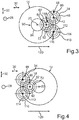
- Fig. 3 shows a third embodiment, wherein Fig. 4 shows a fourth embodiment.
- the axle drive device 10 can have a second electrical machine 110, wherein the previous and following explanations regarding the first electrical machine 34 can easily be transferred to the second electrical machine 110 and vice versa.
- a dashed line 113 is shown in each case, which covers an area C of Fig. 1 respectively from Fig. 2 surrounds.
- this area C components in the form of the electrical machine 34, the planetary gear stage 46 and the spur gear 60 are shown or contained, wherein the components shown or illustrated in the area C can advantageously be provided twice, which is shown in FIG Figures 3 and 4 is illustrated.
- a third planetary gear stage is assigned to the second electrical machine 110, to which the previous and following explanations relating to the electrical machine 34 and the spur gear 60 can easily be transferred, but then with regard to the second electrical machine 110 and to a further spur gear 112, which is driven by the second electrical machine 110, in particular via the in Fig. 3 with 114 designated third planetary gear stage, is drivable.
- the further spur gear 112 meshes with the second spur gear 62 of the first spur gear stage 48, so that, for example, the further spur gear 112 belongs to the first spur gear stage 48.
- the second electrical machine 110 also has a second stator and a second rotor, which can be rotated about a further machine axis of rotation 116 relative to the second stator.
- the respective rotor can be driven by the respective stator and can thereby be rotated about the respective machine axis of rotation 42 or 116.
- the machine axis of rotation 116 is arranged offset from the machine axis of rotation 42, from the main axis of rotation 84 and from the wheel axis of rotation 20.
- the main axis of rotation 84 and the wheel axis of rotation 20 lie in a plane spanned by the transverse direction of the vehicle and the longitudinal direction of the vehicle, which plane thus runs at least substantially perpendicular to the vertical direction of the vehicle.
- the machine axes of rotation 42 and 116 lie in a common plane spanned by the vertical direction of the vehicle and the transverse direction of the vehicle and, for example, perpendicular to the longitudinal direction of the vehicle, with the second electrical machine 110 in particular having the first electrical plane along a direction perpendicular to the transverse direction of the vehicle, in particular along the vertical direction of the vehicle Machine 34 is in alignment.
- the electrical machines 34 and 110 are arranged one above the other in the vertical direction of the vehicle, whereby they are arranged congruently, for example, in such a way that the electrical machine 110 is completely covered upward in the vertical direction of the vehicle by the electric machine 34, while the electrical machine 34 is downward in the vertical direction of the vehicle is completely covered by the electrical machine 110.
- the electrical machines 34 and 110 form a gusset 118 in which at least part of the spur gear 92 is arranged, so that the spur gear 92, in particular the mentioned part of the spur gear 92, in the vertical direction of the vehicle upwards through the electrical machine 34 and in the vertical direction of the vehicle is covered at the bottom by the electrical machine 110.
- FIG. 3 the forward direction of travel of the motor vehicle 12 is illustrated by an arrow 120.
- the electrical machines 34 and 110 are arranged in front of the drive wheel 14 and 18 or in front of the wheel axis of rotation 20, the electrical machine 34 and 110 in the case of FIG Fig. 4
- the fourth embodiment shown are arranged behind the drive wheel 14 or behind the wheel axis of rotation 20.
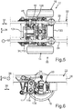
- Fig. 5 shows the motor vehicle 12 in sections in a schematic plan view, with FIG Fig. 5 the integration of the axle drive device 10 between the longitudinal members 24 and 26 can be seen particularly well.
- Fig. 5 122 designates an installation space which is available in particular in the third embodiment and in which, for example, power electronics and / or at least one cooler and, for example, oil and / or water connections can be arranged.
- the cooler is, for example, a heat exchanger and / or an oil and / or water cooler.
- Fig. 5 124 denotes an installation space that is available in the fourth embodiment in particular, in which, for example, power electronics and / or at least one cooler, in particular designed as a heat exchanger, and optionally oil and / or water connections can be arranged, the previous and following statements on the installation space 122 can also be transferred to the installation space 124 and vice versa. It is thus possible for a cooler, in particular an oil cooler, and / or power electronics to be arranged on a side of the first electrical machine 34 facing away from the axle gear 64 or on a side of the axle gear 64 facing away from the first electric machine 34.
- the first planetary gear stage 46 can be omitted, so that the second planetary gear stage 72 is then referred to as the first planetary gear stage, for example with regard to the designation or terminology, and is provided, for example, as the single planetary gear stage.
- the electrical machines 34 and 110 it is conceivable to provide only one of the electrical machines 34 and 110 in the axle drive device 10, so that, for example, precisely one electrical machine 34 or 110 is provided. A sufficiently advantageous drive of the drive wheels 14 and 18 with sufficient power can also be achieved in this way.
- an actuator 126 can be seen, by means of which, for example, the switching element 82 is movable, in particular displaceable, so that
- the actuator system 126 is the aforementioned actuator for moving or shifting the switching element 82.
- FIG. 6 the motor vehicle 12 excerpts in a schematic side view, wherein from Fig. 6 the placement of the electrical machines 34 and 110 arranged one above the other can be seen particularly well. Besides, it's off Fig. 6 a stabilization support 128 can be seen.
- the axle 16 designed for example as a front or rear axle
- the electric machines 34 and 110 which can be operated as electric motors
- the respective planetary gear stage 46 or 114 designed as a planetary gear
- directly on the respective electrical machine 34 or 110 is flanged on and thus forms, with the respective electrical machine 34 or 110, for example, a module that is particularly easy to handle and assemble.
- the second and first embodiment are connected to the spur gear stage 48 via the sun gear 74 in the manner described - in the second embodiment the second planetary gear stage 72 is connected via the ring gear 76 the first spur gear stage 48 is connected.
- the ring gear 76 has its internal toothing, via which the ring gear 76 meshes with the planet gears 80.
- the ring gear 76 for example, has external toothing by which the spur gear 62 is formed. The ring gear 76 or the spur gear 62 meshes with the spur gear 60 via the named external toothing of the ring gear 76.
- the sun gear 74 thus represents a drive for the planetary gear stage 72, with the second embodiment driving the planetary gear stage 72 through the ring gear 76 is realized.
- the Planet carrier 78 is an output of the planetary gear stage 72, which is connected to the second spur gear stage 90 via the output.
- the spur gear stage 90 is a further or second spur gear group via which the respective drive torque or the summed drive torques and thus a total torque resulting from the drive torques is transmitted to the axle gear 64, which is designed as a differential, for example.
Description
Die Erfindung betrifft eine elektrische Achsantriebsvorrichtung für ein Kraftfahrzeug gemäß dem Oberbegriff von Patentanspruch 1, eine elektrische Achsantriebsvorrichtung für ein Kraftfahrzeug gemäß dem Oberbegriff von Patentanspruch 13 sowie ein Kraftfahrzeug mit einer solchen elektrischen Achsantriebsvorrichtung.The invention relates to an electric axle drive device for a motor vehicle according to the preamble of claim 1, an electric axle drive device for a motor vehicle according to the preamble of claim 13 and a motor vehicle with such an electric axle drive device.
Eine elektrische Achsantriebsvorrichtung für ein Kraftfahrzeug ist beispielsweise der
Aus der
Aus der
Schließlich ist aus der gattungsgemäßen
Aufgabe der vorliegenden Erfindung ist es, eine elektrische Achsantriebsvorrichtung und ein Kraftfahrzeug der eingangs genannten derart weiterzuentwickeln, dass ein besonders vorteilhafter Betrieb sowie gleichzeitig eine besonders kompakte Bauweise der elektrischen Achsantriebsvorrichtung realisierbar sind.The object of the present invention is to further develop an electric axle drive device and a motor vehicle of the type mentioned at the beginning in such a way that particularly advantageous operation and, at the same time, a particularly compact design of the electric axle drive device can be implemented.
Diese Aufgabe wird durch eine elektrische Achsantriebsvorrichtung mit den Merkmalen des Patentanspruchs 1, durch eine elektrische Achsantriebsvorrichtung mit den Merkmalen des Patentanspruchs 13 sowie durch ein Nutzfahrzeug mit den Merkmalen des Patentanspruchs 12 gelöst. Vorteilhafte Ausgestaltungen mit zweckmäßigen Weiterbildungen der Erfindung sind in den übrigen Ansprüchen angegeben.This object is achieved by an electric axle drive device with the features of claim 1, by an electric axle drive device with the features of claim 13 and by a utility vehicle with the features of
Um eine elektrische Achsantriebsvorrichtung der im Oberbegriff des Patentanspruchs 1 angegebenen Art derart darzustellen, ist es vorgesehen, dass die elektrische Achsantriebsvorrichtung ein über das Getriebe von der elektrischen Maschine antreibbares Achsgetriebe aufweist, über welches das Antriebsrad von der ersten elektrischen Maschine antreibbar ist. Hierdurch lässt sich ein besonders vorteilhafter Betrieb realisieren, da das wenigstens eine Antriebsrad besonders vorteilhaft, insbesondere mit einer besonders vorteilhaften Übersetzung, von der elektrischen Maschine angetrieben werden kann. Insbesondere ist es möglich, das wenigstens eine Antriebsrad und zumindest ein zweites Antriebsrad über das Achsgetriebe und das Getriebe von der elektrischen Maschine anzutreiben, wobei die vorigen und folgenden Ausführungen zu dem wenigstens einen Antriebsrads ohne weiteres auch auf das zumindest eine zweite Antriebsrad übertragen werden können und umgekehrt. Die Antriebsräder sind dabei beispielsweise einer Achse, insbesondere einer Hinterachse oder einer Vorderachse, zugeordnet, sodass die Achse beziehungsweise die Antriebsräder der Achse mittels der elektrischen Maschine besonders vorteilhaft angetrieben werden können, insbesondere über das Achsgetriebe und das Getriebe. Dabei ist das Achsgetriebe vorzugsweise als Differential beziehungsweise Differentialgetriebe, insbesondere als Kegelraddifferential, ausgebildet, sodass sich ein besonders vorteilhafter Betrieb realisieren lässt. Wie von Differentialgetrieben, insbesondere Kegelraddifferentialen, hinlänglich bekannt ist, lässt das Differentialgetriebe beispielsweise Drehzahlunterschiede beziehungsweise einen Drehzahlausgleich zwischen den Antriebsrädern zu, insbesondere bei einer Kurvenfahrt, sodass sich das kurvenäußere Antriebsrad mit einer höheren Drehzahl als das kurveninnere Antriebsrad drehen kann, ohne dass es zu einer übermäßigen Verspannung der Achsantriebsvorrichtung kommt. Hierdurch lässt sich ein besonders vorteilhafter Betrieb realisieren.In order to present an electric axle drive device of the type specified in the preamble of claim 1, it is provided that the electric axle drive device has an axle drive which can be driven by the electric machine via the transmission and via which the drive wheel can be driven by the first electric machine. This enables particularly advantageous operation to be implemented, since the at least one drive wheel can be driven by the electric machine in a particularly advantageous manner, in particular with a particularly advantageous gear ratio. In particular, it is possible that the at least one drive wheel and at least one second drive wheel via the axle drive and the To drive the transmission from the electric machine, the previous and following statements on the at least one drive wheel can be easily transferred to the at least one second drive wheel and vice versa. The drive wheels are assigned to an axle, in particular a rear axle or a front axle, so that the axle or the drive wheels of the axle can be driven particularly advantageously by means of the electric machine, in particular via the axle drive and the gearbox. The axle drive is preferably designed as a differential or differential gear, in particular as a bevel gear differential, so that particularly advantageous operation can be implemented. As is well known from differential gears, in particular bevel gear differentials, the differential gear allows, for example, speed differences or a speed compensation between the drive wheels, especially when cornering, so that the drive wheel on the outside of the curve can rotate at a higher speed than the drive wheel on the inside of the curve without causing a Excessive tension of the final drive device occurs. This enables particularly advantageous operation to be implemented.
Um dabei gleichzeitig eine besonders kompakte Bauweise der elektrischen Achsantriebsvorrichtung realisieren und somit den Bauraumbedarf der elektrischen Achsantriebsvorrichtung besonders gering halten zu können, ist die erste elektrische Maschine - insbesondere bezogen auf eine Einbaulage der elektrischen Achsantriebsvorrichtung - hinsichtlich einer durch die Fahrzeughochrichtung und die Fahrzeuglängsrichtung aufgespannten Längsmittelebene des Kraftfahrzeugs zumindest teilweise auf einer ersten Seite der Längsmittelebene angeordnet, wobei die erste Stirnradgetriebestufe auf einer der ersten Seite in Fahrzeugquerrichtung gegenüberliegenden zweiten Seite der Längsmittelebene angeordnet ist. Die elektrische Achsantriebsvorrichtung nimmt dabei ihre Einbaulage in vollständig hergestelltem Zustand des Kraftfahrzeugs ein, wobei die elektrische Achsantriebsvorrichtung in vollständig hergestelltem Zustand des Kraftfahrzeugs an dem Kraftfahrzeug, insbesondere zumindest mittelbar an einem Aufbau oder an einem Rahmen des Kraftfahrzeugs, gehalten ist. In vollständig hergestelltem Zustand des Kraftfahrzeugs steht dieses beispielsweise auf einer horizontalen Ebene, sodass die Längsmittelebene eine vertikale Längsmittelebene ist, welche in dem vollständig hergestellten Zustand des Kraftfahrzeugs zumindest im Wesentlichen senkrecht zur Fahrzeugquerrichtung, zur Horizontalen beziehungsweise zur horizontalen Ebene verläuft.In order to simultaneously realize a particularly compact design of the electric axle drive device and thus to be able to keep the installation space requirement of the electric axle drive device particularly low, the first electric machine - in particular with regard to an installation position of the electric axle drive device - is in terms of a longitudinal center plane spanned by the vertical direction of the vehicle and the longitudinal direction of the vehicle Motor vehicle arranged at least partially on a first side of the longitudinal center plane, the first spur gear stage being arranged on a second side of the longitudinal center plane opposite the first side in the transverse direction of the vehicle. The electric axle drive device assumes its installation position in the fully manufactured state of the motor vehicle, the electric axle drive device being held in the fully manufactured state of the motor vehicle on the motor vehicle, in particular at least indirectly on a body or on a frame of the motor vehicle. In the fully manufactured state of the motor vehicle, it stands, for example, on a horizontal plane, so that the longitudinal center plane is a vertical longitudinal center plane which, in the fully manufactured state of the motor vehicle, runs at least substantially perpendicular to the transverse direction of the vehicle, to the horizontal or to the horizontal plane.
Somit wird die Längsmittelebene auch als vertikale Längsmittelebene oder als vertikale Fahrzeug-Längsmittelebene bezeichnet. Insbesondere kann unter der Längsmittelebene Folgendes verstanden werden: Das Kraftfahrzeug, insbesondere die elektrische Achsantriebsvorrichtung, weist in seinem beziehungsweise ihrem vollständig hergestellten Zustand eine - insbesondere bezogen auf die Einbaulage - in Fahrzeugquerrichtung verlaufende Breite auf, wobei beispielsweise die Mitte dieser Breite in der Längsmittelebene liegt. Ausgehend von der Mitte beziehungsweise ausgehend von der Längsmittelebene erstreckt sich das Kraftfahrzeug beziehungsweise die elektrische Achsantriebsvorrichtung in Fahrzeugquerrichtung um eine erste Strecke nach links außen hin und in Fahrzeugquerrichtung um eine zweite Strecke nach rechts außen hin, wobei die erste Strecke der zweiten Strecke entspricht beziehungsweise umgekehrt, das heißt wobei die Strecken gleich sind. Dabei ist das Kraftfahrzeug beziehungsweise die elektrische Achsantriebsvorrichtung bezogen auf die Längsmittelebene nicht notwendigerweise symmetrisch ausgebildet, sodass die Längsmittelebene nicht notwendigerweise eine Symmetrieebene des Kraftfahrzeugs beziehungsweise der elektrischen Achsantriebsvorrichtung ist.The longitudinal center plane is thus also referred to as the vertical longitudinal center plane or the vertical longitudinal vehicle center plane. In particular, the longitudinal center plane can be understood to mean the following: The motor vehicle, in particular the electric axle drive device, in its or its fully manufactured state has a width running in the transverse direction of the vehicle, in particular in relation to the installation position, the center of this width lying in the longitudinal center plane, for example. Starting from the center or starting from the longitudinal center plane, the motor vehicle or the electric axle drive device extends in the vehicle transverse direction by a first distance to the left outside and in the vehicle transverse direction by a second distance to the right outside, the first distance corresponding to the second distance or vice versa, that is, where the distances are the same. The motor vehicle or the electric axle drive device is not necessarily designed symmetrically with respect to the longitudinal center plane, so that the longitudinal center plane is not necessarily a plane of symmetry of the motor vehicle or the electric axle drive device.
Dabei weist das Getriebe eine zweite Planetengetriebestufe auf, wodurch auf bauraum- und gewichtsgünstige Weise eine besonders vorteilhafte Übersetzung des Getriebes insgesamt geschaffen werden kann. Dadurch kann das wenigstens eine Antriebsrad beziehungsweise können die Antriebsräder besonders vorteilhaft angetrieben werden, sodass ein besonders vorteilhafter Betrieb realisierbar ist.In this case, the transmission has a second planetary gear stage, as a result of which a particularly advantageous transmission ratio of the transmission as a whole can be created in a manner that is economical in terms of space and weight. As a result, the at least one drive wheel or the drive wheels can be driven particularly advantageously, so that particularly advantageous operation can be implemented.
Insgesamt weist das Getriebe genau zwei Planetengetriebestufen und genau zwei Stirnradgetriebestufen auf.Overall, the transmission has exactly two planetary gear stages and exactly two spur gear stages.
Erfindungsgemäß ist vorgesehen, dass bezogen auf einen Drehmomentenfluss von der elektrischen Maschine zu dem wenigstens einen Antriebsrad die erste Planetengetriebestufe nach der elektrischen Maschine und vor dem Antriebsrad, die erste Stirnradgetriebestufe nach der ersten Planetengetriebestufe und vor dem Antriebsrad, die zweite Planetengetriebestufe nach der ersten Stirnradgetriebestufe und vor dem wenigstens einen Antriebsrad und die zweite Stirnradgetriebestufe nach der zweiten Planetengetriebestufe und vor dem wenigstens einen Antriebsrad angeordnet ist. Es wurde gefunden, dass sich durch diese Anordnung der Planetengetriebestufen und der Stirnradgetriebestufen eine besonders vorteilhafte Gesamtübersetzung des Getriebes beziehungsweise der Achsantriebsvorrichtung insgesamt realisieren lässt, sodass das wenigstens eine Antriebsrad besonders vorteilhaft angetrieben werden kann bei gleichzeitiger Realisierbarkeit einer kompakten Bauweise, das heißt geringer äußerer Abmessungen der Achsantriebsvorrichtung.According to the invention it is provided that, based on a torque flow from the electrical machine to the at least one drive wheel, the first planetary gear stage after the electrical machine and before the drive wheel, the first spur gear stage after the first planetary gear stage and before the drive wheel, the second planetary gear stage after the first spur gear stage and is arranged in front of the at least one drive wheel and the second spur gear stage after the second planetary gear stage and in front of the at least one drive wheel. It has been found that through this arrangement of the planetary gear stages and the spur gear stages, a particularly advantageous overall ratio of the transmission or the axle drive device can be realized overall, so that the at least one drive wheel can be driven particularly advantageously at simultaneous feasibility of a compact design, that is to say small external dimensions of the axle drive device.
Weiterhin erfindungsgemäß hat es sich als besonders vorteilhaft gezeigt, wenn wenigstens ein Bremselement vorgesehen ist, mittels welchem ein Getriebeelement der zweiten Planetengetriebestufe an einem Gehäuse des Getriebes festlegbar ist. Die jeweilige Planetengetriebestufe weist beispielsweise ein Sonnenrad als erstes Getriebeelement, ein Hohlrad als zweites Getriebeelement und wenigstens einen Planetenradträger als drittes Getriebeelement auf. Ferner weist die jeweilige Planetengetriebestufe wenigstens ein Planetenrad auf, welches beispielsweise mit dem jeweiligen Sonnenrad und mit dem jeweiligen Hohlrad kämmt und drehbar an dem Planetenträger gehalten ist. Mittels des wenigstens einen Bremselements ist somit zumindest eines der Getriebeelemente der zweiten Planetengetriebestufe an dem Gehäuse des Getriebes festlegbar, wobei die Getriebeelemente der zweiten Planetengetriebestufe in dem genannten Gehäuse aufgenommen sein können. Das Bremselement ist beispielsweise zwischen wenigstens einem Bremszustand beziehungsweise zwischen wenigstens einer Bremsstellung und wenigstens einem Freigabezustand beziehungsweise einer Freigabestellung umschaltbar, insbesondere bewegbar. Die jeweiligen Getriebeelemente der jeweiligen Planetengetriebestufe, insbesondere der zweiten Planetengetriebestufe, sind beispielsweise um eine gemeinsame Hauptdrehachse relativ zu dem Gehäuse drehbar, insbesondere dann, wenn sich das Bremselement in dem Freigabezustand beziehungsweise in der Freigabestellung befindet und wenn beispielsweise die zweite Planetengetriebestufe angetrieben wird.Furthermore, according to the invention, it has been shown to be particularly advantageous if at least one braking element is provided, by means of which a gear element of the second planetary gear stage can be fixed on a housing of the gear. The respective planetary gear stage has, for example, a sun gear as the first gear element, a ring gear as the second gear element and at least one planet carrier as the third gear element. Furthermore, the respective planetary gear stage has at least one planetary gear which, for example, meshes with the respective sun gear and with the respective ring gear and is rotatably held on the planet carrier. By means of the at least one braking element, at least one of the gear elements of the second planetary gear stage can thus be fixed to the housing of the gear, it being possible for the gear elements of the second planetary gear stage to be accommodated in said housing. The braking element can, for example, be switched, in particular moved, between at least one braking state or between at least one braking position and at least one release state or one release position. The respective gear elements of the respective planetary gear stage, in particular the second planetary gear stage, can for example be rotated about a common main axis of rotation relative to the housing, in particular when the braking element is in the release state or in the release position and when, for example, the second planetary gear stage is being driven.
Mit anderen Worten lässt das Bremselement in seinem Freigabezustand beziehungsweise in seiner Freigabestellung eine Drehung des einen Getriebeelements der zweiten Planetengetriebestufe um die Hauptdrehachse relativ zu dem Gehäuse zu, sodass zumindest das eine Getriebeelement der zweiten Planetengetriebestufe um die Hauptdrehachse relativ zu dem Gehäuse gedreht wird, wenn die zweite Planetengetriebestufe angetrieben wird. Befindet sich jedoch das Bremselement in seiner Bremsstellung beziehungsweise in seinem Bremszustand, so ist das eine Getriebeelement der zweiten Planetengetriebestufe mittels des Bremselements, insbesondere drehfest, an dem Gehäuse festgelegt, sodass sich das eine Getriebeelement der zweiten Planetengetriebestufe insbesondere auch dann nicht um die Hauptdrehachse relativ zu dem Gehäuse dreht, wenn die zweite Planetengetriebestufe angetrieben wird, das heißt wenn Drehmomente in die zweite Planetengetriebestufe eingeleitet werden. Das Bremselement ermöglicht es somit, das eine Getriebeelement der zweiten Planetengetriebestufe bedarfsgerecht an dem Gehäuse, insbesondere drehfest, festzulegen und freizugeben, sodass eine Schaltbarkeit der zweiten Planetengetriebestufe realisiert beziehungsweise realisierbar ist. Hierdurch ist die zweite Planetengetriebestufe als schaltbarer Planetensatz ausgebildet, sodass beispielsweise wenigstens zwei voneinander unterschiedliche Übersetzungen darstellbar sind, über welche das wenigstens eine Antriebsrad von der elektrischen Maschine antreibbar ist. Die Übersetzungen sind dabei dadurch schaltbar, dass das Bremselement zwischen dem Freigabezustand und dem Bremszustand umschaltbar beziehungsweise bewegbar ist. Ferner kann alternativ oder zusätzlich eine Neutralstellung beziehungsweise ein Neutralzustand als Leerlauf dargestellt werden.In other words, in its release state or in its release position, the brake element allows a rotation of one gear element of the second planetary gear stage about the main axis of rotation relative to the housing, so that at least one gear element of the second planetary gear stage is rotated about the main axis of rotation relative to the housing when the second planetary gear stage is driven. However, if the braking element is in its braking position or in its braking state, one gear element of the second planetary gear stage is fixed to the housing by means of the braking element, in particular non-rotatably, so that the one gear element of the second planetary gear stage does not move relative to the main axis of rotation the housing rotates when the second planetary gear stage is driven, that is, when torques are introduced into the second planetary gear stage. The braking element thus makes it possible to use the one transmission element of the second planetary gear stage as required on the housing, in particular non-rotatably, to be fixed and released, so that switchability of the second planetary gear stage is implemented or can be implemented. As a result, the second planetary gear stage is designed as a switchable planetary set, so that, for example, at least two different ratios can be represented, via which the at least one drive wheel can be driven by the electrical machine. The gear ratios can be switched in that the braking element can be switched or moved between the release state and the braking state. Furthermore, as an alternative or in addition, a neutral position or a neutral state can be represented as idling.
Um das Bremselement besonders gewichts- und bauraumgünstig zu realisieren, ist weiterhin erfindungsgemäß vorgesehen, dass das Bremselement das Hohlrad der zweiten Planetengetriebestufe aufweist beziehungsweise als das Hohlrad der zweiten Planetengetriebestufe ausgebildet ist, wobei das Hohlrad der zweiten Planetengetriebestufe in axialer Richtung der zweiten Planetengetriebestufe relativ zu dem Gehäuse verschiebbar ist, um dadurch das Bremselement zwischen der Freigabestellung und der Bremsstellung zu verschieben. Die axiale Richtung der zweiten Planetengetriebestufe fällt dabei beispielsweise mit der Hauptdrehachse der zweiten Planetengetriebestufe zusammen. Bei dieser Ausführungsform kommt dem Hohlrad eine Doppelfunktion zu, da es einerseits zur Realisierung wenigstens einer vorteilhaften Übersetzung und andererseits als das beschriebene Bremselement genutzt wird.In order to realize the braking element in a particularly weight and space-saving manner, the invention further provides that the braking element has the ring gear of the second planetary gear stage or is designed as the ring gear of the second planetary gear stage, the ring gear of the second planetary gear stage in the axial direction of the second planetary gear stage relative to the Housing is displaceable to thereby move the braking element between the release position and the braking position. The axial direction of the second planetary gear stage coincides, for example, with the main axis of rotation of the second planetary gear stage. In this embodiment, the ring gear has a double function, since it is used on the one hand to implement at least one advantageous gear ratio and on the other hand as the braking element described.
Durch die Gesamtheit der Erfindung wird sichergestellt, dass sowohl eine hoch leistungsfähige elektrische Achsantriebsvorrichtung dargestellt wird als auch eine elektrische Achsantriebsvorrichtung, die ausgehend von einer klassischen nichtelektrifizierten Achsantriebsvorrichtung trotz extremer baulicher Einschränkungen zu einer sehr kompakten Baueinheit führt.The entirety of the invention ensures that both a high-performance electric axle drive device is represented and an electric axle drive device that, based on a classic non-electrified axle drive device, leads to a very compact unit despite extreme structural restrictions.
Bei einer besonders vorteilhaften Ausführungsform der Erfindung ist wenigstens ein Verblockungselement vorgesehen, mittels welchem wenigstens zwei der Getriebeelemente der zweiten Planetengetriebestufe miteinander verblockbar sind. Das Verblockungselement ist beispielsweise zwischen wenigstens einem Verblockungszustand beziehungsweise wenigstens einer Verblockungsstellung und wenigstens einem Lösezustand beziehungsweise wenigstens einer Lösestellung umschaltbar, insbesondere bewegbar. In dem Verblockungszustand beziehungsweise in der Verblockungsstellung sind mittels des Verblockungselements die zwei Getriebeelemente der zweiten Planetengetriebestufe miteinander verblockt, das heißt drehfest miteinander verbunden, sodass die zweite Getriebeelemente der zweiten Planetengetriebestufe als Block, das heißt gemeinsam um die Hauptdrehachse umlaufen, insbesondere wenn die zweite Planetengetriebestufe angetrieben wird. Mit anderen Worten drehen sich in dem Verblockungszustand des Verblockungselements die zwei Getriebeelemente gemeinsam um die Hauptdrehachse relativ zu dem Gehäuse, wenn die zweite Planetengetriebestufe angetrieben wird. In dem Lösezustand beziehungsweise in der Lösestellung jedoch gibt das Verblockungselement die zweite Getriebeelemente der zweiten Planetengetriebestufe, insbesondere für eine Relativdrehung zueinander um die Hauptdrehachse, frei, sodass sich die zweite Getriebeelemente insbesondere dann, wenn die zweite Planetengetriebestufe angetrieben wird, um die Hauptdrehachse relativ zueinander und relativ zu dem Gehäuse drehen können. Hierdurch können beispielsweise auf besonders bauraum- und gewichtsgünstige Weise die zuvor genannten, voneinander unterschiedlichen Übersetzungen dargestellt werden, da die zweite Planetengetriebestufe durch Einsatz des Verblockungselements als schaltbare Planetengetriebestufe beziehungsweise als schaltbarer Planetensatz ausgebildet ist beziehungsweise ausgebildet werden kann.In a particularly advantageous embodiment of the invention, at least one locking element is provided, by means of which at least two of the gear elements of the second planetary gear stage can be interlocked with one another. The blocking element can, for example, be switched, in particular moved, between at least one blocking state or at least one blocking position and at least one release state or at least one release position. The two are in the locked state or in the locked position by means of the locking element Gear elements of the second planetary gear stage are interlocked, that is, connected to one another in a rotationally fixed manner, so that the second gear elements of the second planetary gear stage rotate as a block, that is, together around the main axis of rotation, in particular when the second planetary gear stage is driven. In other words, in the locked state of the locking element, the two gear elements rotate together about the main axis of rotation relative to the housing when the second planetary gear stage is driven. In the released state or in the released position, however, the locking element releases the second gear element of the second planetary gear stage, in particular for relative rotation to one another about the main axis of rotation, so that the second gear element, in particular when the second planetary gear stage is driven, revolves around the main axis of rotation relative to one another and can rotate relative to the housing. In this way, for example, the above-mentioned, mutually different ratios can be represented in a particularly space-saving and weight-saving manner, since the second planetary gear stage is or can be designed as a switchable planetary gear stage or as a switchable planetary set by using the locking element.
Um eine besonders kompakte Bauweise darstellen zu können, ist es in weiterer Ausgestaltung der Erfindung vorgesehen, dass die zweite Planetengetriebestufe zumindest teilweise, insbesondere zumindest überwiegend oder vollständig, auf der zweiten Seite der Längsmittelebene angeordnet ist.In order to be able to represent a particularly compact design, it is provided in a further embodiment of the invention that the second planetary gear stage is arranged at least partially, in particular at least predominantly or completely, on the second side of the longitudinal center plane.
Bei einer besonders vorteilhaften Ausführungsform der Erfindung ist die zweite Stirnradgetriebestufe zumindest im Wesentlich in beziehungsweise auf der Längsmittelebene angeordnet. Hierunter ist insbesondere zu verstehen, dass sich die Längsmittelebene durch jeweilige, miteinander kämmende Stirnräder der zweiten Stirnradgetriebestufe erstreckt sodass beispielsweise die Stirnräder der zweiten Stirnradgetriebestufe bezogen auf die Fahrzeugquerrichtung zumindest im Wesentlichen in der Mitte der Achsantriebsvorrichtung beziehungsweise der genannten Achse angeordnet sind.In a particularly advantageous embodiment of the invention, the second spur gear stage is arranged at least essentially in or on the longitudinal center plane. This is to be understood in particular that the longitudinal center plane extends through respective, intermeshing spur gears of the second spur gear stage so that, for example, the spur gears of the second spur gear stage are arranged at least essentially in the center of the axle drive device or said axis with respect to the transverse direction of the vehicle.
Um den Bauraumbedarf der elektrischen Achsantriebsvorrichtung besonders gering halten zu können, ist es bei einer weiteren Ausführungsform der Erfindung vorgesehen, dass die elektrische Maschine zumindest zu zwei Dritteln ihres, insbesondere äußeren, Volumens beziehungsweise ihrer äußeren Abmessungen auf der ersten Seite der Längsmittelebene angeordnet ist.In order to be able to keep the space requirement of the electric axle drive device particularly small, it is provided in a further embodiment of the invention that the electric machine is arranged at least two thirds of its, in particular outer, volume or its outer dimensions on the first side of the longitudinal center plane.
Eine weitere Ausführungsform zeichnet sich dadurch aus, dass eine zweite elektrische Maschine und ein weiteres, von der zweiten elektrischen Maschine antreibbares und mit dem zweiten Stirnrad kämmendes Stirnrad vorgesehen sind. Die zweite elektrische Maschine kann somit Drehmomente als Antriebsmomente bereitstellen, die beispielsweise über das weitere Stirnrad auf das zweite Stirnrad der ersten Stirnradgetriebestufe übertragen werden und somit in das Getriebe eingeleitet werden können. Somit ist die zweite elektrische Maschine über das weitere Stirnrad mit dem zweiten Stirnrad der ersten Stirnradgetriebestufe gekoppelt, wobei die jeweilige Stirnradgetriebestufe auch als Stirnradstufe bezeichnet wird. Die jeweilige Planetengetriebestufe wird auch als Planetenstufen, Planetensatz oder Planetenradsatz bezeichnet.Another embodiment is characterized in that a second electrical machine and a further spur gear that can be driven by the second electrical machine and mesh with the second spur gear are provided. The second electrical machine can thus provide torques as drive torques, which are transmitted, for example, via the further spur gear to the second spur gear of the first spur gear transmission stage and can thus be introduced into the transmission. The second electrical machine is thus coupled via the further spur gear to the second spur gear of the first spur gear stage, the respective spur gear stage also being referred to as a spur gear stage. The respective planetary gear stage is also referred to as a planetary stage, planetary set or planetary gear set.
Dabei ist das wenigstens eine Antriebsrad mittels der zwei elektrischen Maschinen antreibbar, da die jeweilige elektrische Maschine wenigstens ein jeweiliges Drehmoment als Antriebsmoment zum Antreiben des wenigstens einen Antriebsrads bereitstellen kann. Die erste elektrische Maschine kann beispielsweise ihr Antriebsmoment über das erste Stirnrad der ersten Stirnradgetriebestufe bereitstellen, wobei die zweite elektrische Maschine ihr Antriebsmoment über das weitere Stirnrad bereitstellen kann. Die jeweiligen, von den jeweiligen elektrischen Maschinen bereitgestellten Antriebsmomente werden auf das zweite Stirnrad der ersten Stirnradgetriebestufe übertragen und auf das zweite Stirnrad vereinigt, sodass sich ein besonders vorteilhafter und kompakter Antrieb darstellen lässt.The at least one drive wheel can be driven by means of the two electrical machines, since the respective electrical machine can provide at least one respective torque as a drive torque for driving the at least one drive wheel. The first electrical machine can, for example, provide its drive torque via the first spur gear of the first spur gear stage, wherein the second electrical machine can provide its drive torque via the further spur gear. The respective drive torques provided by the respective electrical machines are transmitted to the second spur gear of the first spur gear stage and combined on the second spur gear, so that a particularly advantageous and compact drive can be produced.
Um den Bauraumbedarf besonders gering halten zu können, ist es in weiterer Ausgestaltung der Erfindung vorgesehen, dass die zweite elektrische Maschine entlang einer senkrecht zur Fahrzeugquerrichtung und somit beispielsweise zumindest im Wesentlichen parallel zur Längsmittelebene verlaufende Richtung mit der ersten elektrischen Maschine fluchtet. Die zweite elektrische Maschine weist beispielsweise einen zweiten Stator und einen zweiten Rotor auf, welcher um eine zweite Maschinendrehachse relativ zu dem zweiten Stator drehbar ist. Dabei ist es vorzugsweise vorgesehen, dass die zweite Maschinendrehachse desachsiert von der ersten Maschinendrehachse ist, wobei vorzugsweise die jeweilige Maschinendrehachse desachsiert zur Raddrehachse ist. Ferner ist es vorzugsweise vorgesehen, dass die Maschinendrehachsen in einer gemeinsamen Ebene liegen, welche beispielsweise parallel zur Fahrzeughochrichtung beziehungsweise parallel zur Längsmittelebene verläuft beziehungsweise mit der Längsmittelebene zusammenfällt. Die Raddrehachsen und die jeweilige Maschinendrehachse verlaufen vorzugsweise zumindest im Wesentlichen in Fahrzeugquerrichtung.In order to be able to keep the installation space requirement particularly low, it is provided in a further embodiment of the invention that the second electrical machine is aligned with the first electrical machine along a direction perpendicular to the transverse direction of the vehicle and thus, for example, at least substantially parallel to the longitudinal center plane. The second electrical machine has, for example, a second stator and a second rotor which is rotatable about a second machine axis of rotation relative to the second stator. It is preferably provided that the second machine axis of rotation is offset from the first machine axis of rotation, the respective machine axis of rotation preferably being offset from the wheel axis of rotation. Furthermore, it is preferably provided that the machine axes of rotation lie in a common plane which, for example, runs parallel to the vertical direction of the vehicle or parallel to the longitudinal center plane or coincides with the longitudinal center plane. The wheel rotation axes and the respective machine axis of rotation preferably run at least substantially in the transverse direction of the vehicle.
Eine weitere Ausführungsform zeichnet sich dadurch aus, dass die erste Planetengetriebestufe, die erste elektrische Maschine und die erste Stirnradgetriebestufe in einem gemeinsamen Gehäuse, insbesondere in dem zuvor genannten Gehäuse, angeordnet sind, wobei das Gehäuse zu jeweils gleichen Teilen auf der ersten Seite und auf der zweiten Seite der Längsmittelebene angeordnet ist. Hierdurch lässt sich eine kompakte Bauweise darstellen. Ferner bilden beispielsweise die erste Planetengetriebestufe, die erste elektrische Maschine und die erste Stirnradgetriebestufe sowie das diesen gemeinsame Gehäuse ein Modul, welches einfach und kostengünstig gehandhabt und montiert werden kann.Another embodiment is characterized in that the first planetary gear stage, the first electrical machine and the first spur gear stage are arranged in a common housing, in particular in the aforementioned housing, the housing being in equal parts on the first side and on the second side of the longitudinal center plane is arranged. This allows a compact design to be achieved. Furthermore, for example, the first planetary gear stage, the first electrical machine and the first spur gear stage as well as the housing common to them form a module which can be handled and installed easily and inexpensively.
Um einen besonders vorteilhaften Betrieb zu realisieren, hat es sich schließlich als besonders vorteilhaft gezeigt, wenn ein Ölkühler und/oder eine Leistungselektronik auf einer dem Achsgetriebe abgewandten Seite der ersten elektrischen Maschine oder auf einer der ersten elektrischen Maschine abgewandten Seite des Achsgetriebes angeordnet sind beziehungsweise ist.In order to achieve particularly advantageous operation, it has finally been shown to be particularly advantageous if an oil cooler and / or power electronics are or is arranged on a side of the first electrical machine facing away from the axle drive or on a side of the axle drive facing away from the first electrical machine .
Um den Bauraumbedarf besonders gering halten zu können, ist die zweite elektrische Maschine hinsichtlich einer durch die Fahrzeugquerrichtung und die Fahrzeuglängsrichtung aufgespannten weiteren Ebene des Kraftfahrzeugs auf einer dritten Seite der weiteren Ebene angeordnet, wobei die erste elektrische Maschine auf einer dritten Seite in Fahrzeughochrichtung gegenüberliegenden vierten Seite der weiteren Ebene angeordnet ist. Beispielsweise sind die elektrische Maschine in Fahrzeughochrichtung übereinander angeordnet, wobei beispielsweise eine der elektrischen Maschinen in Fahrzeughochrichtung nach oben hin zumindest teilweise, insbesondere zumindest überwiegend oder vollständig, durch die andere elektrische Maschine überdeckt ist beziehungsweise sodass beispielsweise die andere elektrische Maschine in Fahrzeughochrichtung nach unten hin zumindest teilweise, insbesondere zumindest überwiegend oder vollständig, durch eine elektrische Maschine überdeckt ist.In order to be able to keep the installation space requirement particularly low, the second electric machine is arranged on a third side of the further level with regard to a further plane of the motor vehicle spanned by the transverse direction of the vehicle and the longitudinal direction of the vehicle, with the first electric machine on a third side opposite the fourth side in the vertical direction of the vehicle the further level is arranged. For example, the electrical machines are arranged one above the other in the vertical direction of the vehicle, for example one of the electrical machines in the vertical direction of the vehicle is at least partially, in particular at least predominantly or completely, covered by the other electrical machine or so that, for example, the other electrical machine is at least downward in the vertical direction of the vehicle is partially, in particular at least predominantly or completely, covered by an electrical machine.
Zur Erfindung gehört auch ein Kraftfahrzeug, insbesondere ein Nutzfahrzeug, mit wenigstens einer erfindungsgemäßen elektrischen Achsantriebsvorrichtung. Vorteile und vorteilhafte Ausgestaltungen der erfindungsgemäßen Achsantriebsvorrichtung sind als Vorteile und vorteilhafte Ausgestaltungen des erfindungsgemäßen Kraftfahrzeugs anzusehen und umgekehrt.The invention also includes a motor vehicle, in particular a utility vehicle, with at least one electrical axle drive device according to the invention. Advantages and advantageous refinements of the axle drive device according to the invention are to be regarded as advantages and advantageous refinements of the motor vehicle according to the invention, and vice versa.
Dabei hat es sich als besonders vorteilhaft gezeigt, wenn das Kraftfahrzeug wenigstens zwei Längsträger aufweist, welche beispielsweise in Fahrzeugquerrichtung voneinander beabstandet sind und sich zumindest im Wesentlichen in Fahrzeuglängsrichtung erstrecken. Dabei sind alle Komponenten der Achsantriebsvorrichtung in Fahrzeugquerrichtung zwischen den Längsträgern angeordnet. Die Längsträger sind beispielsweise Bestandteil eines Rahmens des beispielsweise als Nutzfahrzeug ausgebildeten Kraftfahrzeugs, wobei der Rahmen beispielsweise auch wenigstens einen Querträger umfasst, durch welchen die Längsträger beispielsweise miteinander verbunden sind.It has been shown to be particularly advantageous if the motor vehicle has at least two longitudinal members, which are spaced apart from one another in the transverse direction of the vehicle, for example, and extend at least substantially in the longitudinal direction of the vehicle. All components of the axle drive device are arranged between the longitudinal members in the transverse direction of the vehicle. The side members are, for example, part of a frame of the motor vehicle, for example designed as a utility vehicle, the frame also including at least one cross member by which the side members are connected to one another, for example.
Der Erfindung liegt dabei insbesondere folgende Erkenntnis zugrunde: Die Platzierung eines elektrischen Antriebs, das heißt einer elektrischen Achsantriebsvorrichtung an einer beispielsweise als Vorder- oder Hinterachse ausgebildeten Achse eines Kraftfahrzeugs in einem bestehenden Bauraum kann herausfordernd sein, da üblicherweise ein nur sehr geringer Bauraum zur Verfügung steht. Erfindungsgemäß lässt sich jedoch nun eine besonders kompakte Bauweise realisieren, sodass die als elektrischer Antrieb fungierende elektrische Achsantriebsvorrichtung inklusive einer besonders vorteilhaften, insbesondere durch das Getriebe sowie durch das Achsgetriebe dargestellten Übersetzung beispielsweise besonders vorteilhaft in einem bestehenden, auch als Leiterrahmen bezeichneten Rahmen und dabei insbesondere zwischen die Längsträger und zwischen etwaig vorgesehene Federbälge integriert werden kann. Üblicherweise ist eine solche Integration insofern ein Problem, als aus fahrdynamischen Gründen eine große Übersetzung beziehungsweise Untersetzung mit einem Wert von bis zu 70 wünschenswert ist. Die Untersetzung beziehungsweise Übersetzung wird üblicherweise mit i bezeichnet, wobei vorzugsweise gelten soll, dass i bis zu 70 beträgt. Üblicherweise ist zur Realisierung einer solch hohen Übersetzung beziehungsweise Untersetzung ein entsprechend großer Bauraum erforderlich. Erfindungsgemäß lässt sich nun eine solch kompakte Bauweise der elektrischen Achsantriebsvorrichtung realisieren, dass beispielsweise bereits bestehende Achsbrücken, insbesondere Hinterachsbrücken, ohne oder mit nur sehr geringen Änderungen übernommen und somit beibehalten werden können.The invention is based in particular on the following knowledge: The placement of an electric drive, i.e. an electric axle drive device on an axle of a motor vehicle, for example designed as a front or rear axle, in an existing installation space can be challenging because usually only a very small installation space is available . According to the invention, however, a particularly compact design can now be realized, so that the electric axle drive device functioning as an electric drive including a particularly advantageous translation, in particular represented by the gearbox and the axle drive, is particularly advantageous, for example, in an existing frame, also referred to as a ladder frame, and in particular between the side members and can be integrated between any spring bellows that may be provided. Such an integration is usually a problem insofar as a large gear ratio or reduction ratio with a value of up to 70 is desirable for reasons of driving dynamics. The reduction or translation is usually denoted by i, whereby it should preferably apply that i is up to 70. Usually, a correspondingly large installation space is required to implement such a high gear ratio or reduction ratio. According to the invention, such a compact design of the electric axle drive device can now be realized that, for example, already existing axle bridges, in particular rear axle bridges, can be adopted and thus retained without or with only very minor changes.
Insbesondere durch Einsatz des Bremselements und des Verblockungselements können wenigstens zwei schaltbare Übersetzungen sowie eine Neutralstellung des Getriebes beziehungsweise der Achsantriebsvorrichtung insgesamt dargestellt werden, und das auf besonders bauraumgünstige Weise. Über die zweite Stirnradgetriebestufe, wobei die jeweilige Stirnradgetriebestufe auch als Stirnradgruppe bezeichnet wird, kann das jeweilige Antriebsmoment auf das vorzugsweise als Differential ausgebildete Achsgetriebe übertragen werden. Ferner ist es möglich, die elektrischen Maschinen zusammen mit dem Getriebe in Fahrzeuglängsrichtung beziehungsweise in Vorwärtsfahrtrichtung vor oder hinter dem wenigstens einen Antriebsrad beziehungsweise der Achse zu positionieren, sodass eine bedarfsgerechte Positionierung der jeweiligen elektrischen Maschine und des Getriebes darstellbar ist.In particular, by using the braking element and the locking element, at least two switchable gear ratios and a neutral position of the transmission or the axle drive device can be represented as a whole, and this in a manner that is particularly economical in terms of installation space. This can be done via the second spur gear stage, the respective spur gear stage also being referred to as a spur gear group respective drive torque are transmitted to the axle drive, which is preferably designed as a differential. It is also possible to position the electrical machines together with the transmission in the longitudinal direction of the vehicle or in the forward direction in front of or behind the at least one drive wheel or the axle, so that the respective electrical machine and the transmission can be positioned as required.
Um das wenigstens eine Antriebsrad anzutreiben, wird die jeweilige elektrische Maschine beispielsweise in einem Motorbetrieb und somit als Elektromotor betrieben. Hierzu wird beispielsweise die elektrische Maschine mit elektrischer Energie beziehungsweise elektrischem Strom versorgt, die beziehungsweise der in einem Energiespeicher gespeichert ist. Der Energiespeicher ist beispielsweise als Batterie, insbesondere als Hochvolt-Batterie (HV-Batterie), ausgebildet. Bei der erfindungsgemäßen Achsantriebsvorrichtung lässt sich eine kompakte Schachtelung des Getriebes realisieren, sodass die erste elektrische Maschine beziehungsweise die beiden elektrischen Maschinen sowie das Getriebe zwischen den Längsträgern und etwaig vorgesehenen Federbalgen positioniert werden können. Hierdurch kann beispielsweise zusätzlicher Bauraum geschaffen werden, in welchem der zuvor genannte Energiespeicher beziehungsweise mehrerer solcher Energiespeicher angeordnet werden können. In der Folge kann das Kraftfahrzeug eine besonders hohe Menge an elektrischer Energie zum Antreiben der jeweiligen elektrischen Maschine mitführen, sodass eine besonders hohe elektrische Reichweite darstellbar ist, über welche das Kraftfahrzeug elektrische angetrieben werden kann. Außerdem können beispielsweise bereits bestehende Achskomponenten und der Rahmen als Chassis beibehalten und weiterverwendet werden, und dies ohne oder mit nur geringen Änderungen.In order to drive the at least one drive wheel, the respective electrical machine is operated, for example, in motor mode and thus as an electric motor. For this purpose, for example, the electrical machine is supplied with electrical energy or electrical current that is stored in an energy store. The energy store is designed, for example, as a battery, in particular as a high-voltage battery (HV battery). With the axle drive device according to the invention, a compact nesting of the transmission can be realized so that the first electrical machine or the two electrical machines as well as the transmission can be positioned between the longitudinal members and any bellows provided. In this way, for example, additional installation space can be created in which the aforementioned energy store or a plurality of such energy stores can be arranged. As a result, the motor vehicle can carry a particularly large amount of electrical energy for driving the respective electrical machine, so that a particularly long electrical range can be represented over which the motor vehicle can be electrically driven. In addition, for example, existing axle components and the frame can be retained and re-used as a chassis, with little or no changes.
Durch die beschriebene Möglichkeit, zwei schaltbare Übersetzungen darzustellen, kann ein besonders vorteilhafter Antrieb des wenigstens einen Antriebsrads dargestellt werden. Außerdem ist die beschriebene Leerlaufstellung möglich, sodass beispielsweise auch dann, wenn die jeweilige elektrische Maschine das Getriebe antreibt, ein Antreiben des wenigstens einen Antriebsrads unterbleibt. Durch die unterschiedlichen möglichen Positionierungen der jeweiligen elektrischen Maschine des Getriebes, insbesondere vor und hinter der Achse, kann Platz für weitere Komponenten wie beispielsweise Energiespeicher geschaffen werden.The described possibility of displaying two switchable gear ratios enables a particularly advantageous drive of the at least one drive wheel to be displayed. In addition, the described neutral position is possible so that, for example, even when the respective electrical machine drives the transmission, the at least one drive wheel is not driven. Due to the different possible positions of the respective electrical machine of the transmission, in particular in front of and behind the axis, space can be created for further components such as energy storage devices.
Ferner hat es sich als vorteilhaft gezeigt, wenn das Bremselement das Sonnenrad der zweiten Planetengetriebestufe aufweist beziehungsweise als das Sonnenrad der zweitenFurthermore, it has been shown to be advantageous if the braking element has the sun gear of the second planetary gear stage or as the sun gear of the second
Planetengetriebestufe ausgebildet ist, wobei das als das Bremselement ausgebildete Sonnenrad der Planetengetriebestufe dann als Verschiebesonne ausgebildet ist. Die Verschiebesonne ist dabei in axialer Richtung der zweiten Planetengetriebestufe relativ zu dem Gehäuse verschiebbar und dadurch zwischen dem Bremszustand beziehungsweise der Bremsstellung und dem Freigabezustand beziehungsweise der Freigabestellung bewegbar beziehungsweise verschiebbar, insbesondere relativ zu dem Gehäuse. Wird beispielsweise - wie zuvor alternativ beschrieben - das Hohlrad der zweiten Planetengetriebestufe als das Bremselement verwendet, so ist dann das Hohlrad als Verschiebehohlrad ausgebildet, da das Hohlrad in axialer Richtung der zweiten Planetengetriebestufe relativ zu dem Gehäuse zwischen der Bremsstellung und der Freigabestellung bewegt beziehungsweise verschoben werden kann.Planetary gear stage is formed, wherein the sun gear formed as the braking element of the planetary gear stage is then formed as a sliding sun. The sliding sun is displaceable in the axial direction of the second planetary gear stage relative to the housing and thereby movable or displaceable between the braking state or the braking position and the release state or the release position, in particular relative to the housing. If, for example - as previously described alternatively - the ring gear of the second planetary gear stage is used as the braking element, then the ring gear is designed as a sliding ring gear, since the ring gear is moved or shifted in the axial direction of the second planetary gear stage relative to the housing between the braking position and the release position can.
Als besonders vorteilhaft hat es sich ferner gezeigt, wenn die erste Planetengetriebestufe über das Sonnenrad der ersten Planetengetriebestufe von der ersten elektrischen Maschine antreibbar, insbesondere an die erste elektrische Maschine angebunden, ist. Hierunter ist insbesondere zu verstehen, dass das Sonnenrad der ersten Planetengetriebestufe drehfest mit der ersten elektrischen Maschine, insbesondere mit dem Rotor der ersten elektrischen Maschine, verbunden oder verbindbar ist, wobei insbesondere das Sonnenrad der Planetengetriebestufe vorzugsweise koaxial zu dem Rotor der ersten elektrischen Maschine angeordnet ist.It has also been shown to be particularly advantageous if the first planetary gear stage can be driven by the first electrical machine, in particular connected to the first electrical machine, via the sun gear of the first planetary gear stage. This means in particular that the sun gear of the first planetary gear stage is non-rotatably connected or connectable to the first electrical machine, in particular to the rotor of the first electrical machine, the sun gear of the planetary gear stage in particular preferably being arranged coaxially with the rotor of the first electrical machine .
Ferner hat es sich als besonders vorteilhaft gezeigt, wenn die erste Planetengetriebestufe über den Planetenträger der ersten Planetengetriebestufe an die erste Stirnradgetriebestufe, insbesondere an das erste Stirnrad der ersten Stirnradgetriebestufe, angebunden ist. Hierzu ist beispielsweise der Planetenträger der ersten Planetengetriebestufe drehfest mit dem ersten Stirnrad der ersten Stirnradgetriebestufe verbindbar oder verbunden, wobei vorzugsweise der Planetenträger der ersten Planetengetriebestufe koaxial zu dem ersten Stirnrad der ersten Stirnradgetriebestufe angeordnet ist.Furthermore, it has been shown to be particularly advantageous if the first planetary gear stage is connected to the first spur gear stage, in particular to the first spur gear of the first spur gear stage, via the planet carrier of the first planetary gear stage. For this purpose, for example, the planet carrier of the first planetary gear stage is rotatably connectable or connected to the first spur gear of the first spur gear stage, the planet carrier of the first planetary gear stage preferably being arranged coaxially with the first spur gear of the first spur gear stage.
Die zweite Stirnradgetriebestufe umfasst beispielsweise ein drittes Stirnrad und ein mit dem dritten Stirnrad kämmendes viertes Stirnrad, wobei beispielsweise das wenigstens eine Antriebsrad über das vierte Stirnrad von dem dritten Stirnrad antreibbar ist. Somit ist beispielsweise bezogen auf den zuvor genannten Drehmomentenfluss das dritte Stirnrad nach der zweiten Planetengetriebestufe und vor dem wenigstens einen Antriebsrad angeordnet, wobei das vierte Stirnrad nach dem dritten Stirnrad und vor dem wenigstens einen Antriebsrad angeordnet ist.The second spur gear stage includes, for example, a third spur gear and a fourth spur gear meshing with the third spur gear, wherein, for example, the at least one drive gear can be driven by the third spur gear via the fourth spur gear. Thus, for example, based on the aforementioned torque flow, the third spur gear is arranged after the second planetary gear stage and in front of the at least one drive gear, the fourth spur gear being arranged after the third spur gear and in front of the at least one drive gear.
Dabei hat es sich als vorteilhaft gezeigt, wenn die zweite Planetengetriebestufe über den Planetenträger der zweiten Planetengetriebestufe an die zweite Stirnradgetriebestufe, insbesondere an das dritte Stirnrad, angebunden ist. Hierzu ist beispielsweise der Planetenträger der zweiten Planetengetriebestufe drehfest mit dem dritten Stirnrad verbunden oder verbindbar, wobei vorzugsweise vorgesehen ist, dass das dritte Stirnrad koaxial zu dem Planetenträger der zweiten Planetengetriebestufe angeordnet ist.It has been shown to be advantageous if the second planetary gear stage is connected to the second spur gear stage, in particular to the third spur gear, via the planet carrier of the second planetary gear stage. For this purpose, for example, the planet carrier of the second planetary gear stage is connected or connectable to the third spur gear in a rotationally fixed manner, whereby it is preferably provided that the third spur gear is arranged coaxially with the planet carrier of the second planetary gear stage.
Eine weitere Ausführungsform zeichnet sich dadurch aus, dass die zweite Planetengetriebestufe über das Sonnenrad der zweiten Planetengetriebestufe an die erste Stirnradgetriebestufe angebunden ist. Hierzu beispielsweise das Sonnenrad der zweiten Planetengetriebestufe drehfest mit dem zweiten Stirnrad der ersten Stirnradgetriebestufe verbunden oder verbindbar, wobei vorzugsweise vorgesehen ist, dass das Sonnenrad der zweiten Planetengetriebestufe koaxial zum zweiten Stirnrad der ersten Stirnradgetriebestufe angeordnet ist.Another embodiment is characterized in that the second planetary gear stage is connected to the first spur gear stage via the sun gear of the second planetary gear stage. For this purpose, for example, the sun gear of the second planetary gear stage is non-rotatably connected or connectable to the second spur gear of the first spur gear stage, whereby it is preferably provided that the sun gear of the second planetary gear stage is arranged coaxially to the second spur gear of the first spur gear stage.
Alternativ hat es sich als besonders vorteilhaft gezeigt, wenn die zweite Planetengetriebestufe über das Hohlrad der zweiten Planetengetriebestufe an die erste Stirnradgetriebestufe, insbesondere an das zweite Stirnrad der ersten Stirnradgetriebestufe, angebunden ist. Hierzu weist beispielsweise das Hohlrad der zweiten Planetengetriebestufe eine Verzahnung, insbesondere eine Außenverzahnung, auf, durch welche das zweite Stirnrad der ersten Stirnradgetriebestufe gebildet ist. Dabei sind beispielsweise das Hohlrad der zweiten Planetengetriebestufe und die Stirnräder der ersten Stirnradgetriebestufe in einer gemeinsamen Ebene und dabei beispielsweise in radialer Richtung der ersten Stirnradgetriebestufe nebeneinander beziehungsweise aufeinanderfolgend angeordnet.Alternatively, it has been shown to be particularly advantageous if the second planetary gear stage is connected to the first spur gear stage, in particular to the second spur gear of the first spur gear stage, via the ring gear of the second planetary gear stage. For this purpose, for example, the ring gear of the second planetary gear stage has teeth, in particular external teeth, by which the second spur gear of the first spur gear stage is formed. Here, for example, the ring gear of the second planetary gear stage and the spur gears of the first spur gear stage are arranged in a common plane and, for example, in the radial direction of the first spur gear stage next to one another or one after the other.
Die vorigen und folgenden Ausführungen zur Schaltbarkeit der zweiten Planetengetriebestufe können ohne weiteres auch auf die erste Planetengetriebestufe übertragen werden und umgekehrt, sodass alternativ oder zusätzlich zur Schaltbarkeit der zweiten Planetengetriebestufe vorgesehen sein kann, dass die erste Planetengetriebestufe schaltbar ist. Somit ist beispielsweise wenigstens ein zweites Bremselement vorgesehen, mittels welchem eines der Getriebeelemente der ersten Planetengetriebestufe an einem Gehäuse des Getriebes, insbesondere drehfest, festlegbar ist, sodass beispielsweise die vorigen und folgenden Ausführungen zumindest des einen Bremselement auch auf das zweite Bremselement, dann bezogen auf die erste Getriebestufe, übertragen werden können und umgekehrt.The previous and following statements on the switchability of the second planetary gear stage can easily be transferred to the first planetary gear stage and vice versa, so that alternatively or in addition to the switchability of the second planetary gear stage it can be provided that the first planetary gear stage is switchable. Thus, for example, at least one second brake element is provided, by means of which one of the transmission elements of the first planetary gear stage can be fixed to a housing of the transmission, in particular non-rotatably, so that, for example, the previous and following explanations of at least one brake element also apply to the second brake element, then based on the first gear stage, can be transmitted and vice versa.
Ist beispielsweise wenigstens ein zweites Verblockungselement vorgesehen, mittels welchem wenigstens zwei Getriebeelemente der ersten Planetengetriebestufe miteinander verblockbar sind, sodass beispielsweise die vorigen und folgenden Ausführungen zu wenigstens einem Verblockungselement auf das zweite Verblockungselement, dann bezogen auf die erste Planetengetriebestufe, übertragen werden können und umgekehrt.For example, if at least one second locking element is provided, by means of which at least two gear elements of the first planetary gear stage can be interlocked, so that, for example, the previous and following statements on at least one locking element can be transferred to the second locking element, then based on the first planetary gear stage, and vice versa.
Eine weitere Ausführungsform zeichnet sich dadurch aus, dass dem Achsgetriebe eine Differentialsperre zugeordnet ist, deren Funktion bezüglich Differentialgetrieben hinlänglich und insbesondere aus dem allgemeinen Stand der Technik bekannt ist. Durch den Einsatz der Differentialsperre kann das Achsgetriebe zu einem Sperrdifferential weitergebildet werden. Mittels der Differentialsperre kann beispielsweise der zuvor genannte Drehzahlausgleich eingeschränkt beziehungsweise unterbunden werden, sodass die Antriebsräder über die Differentialsperre miteinander koppelbar sind.Another embodiment is characterized in that a differential lock is assigned to the axle drive, the function of which with respect to differential drives is sufficiently well known and in particular is known from the general prior art. By using the differential lock, the axle drive can be developed into a limited slip differential. By means of the differential lock, for example, the aforementioned speed compensation can be restricted or prevented so that the drive wheels can be coupled to one another via the differential lock.
Dabei hat es sich als besonders vorteilhaft gezeigt, wenn die Differentialsperre zumindest teilweise, insbesondere zumindest überwiegend oder vollständig, auf der ersten Seite der Längsmittelebene angeordnet ist, da dort ausreichend Platz für einen zugehörigen Aktor zur Verfügung steht. Mittels des Aktors kann beispielsweise wenigstens ein Sperrelement der insbesondere als elektronische Differentialsperre ausgebildeten Differentialsperre betätigt beziehungsweise bewegt werden.It has been shown to be particularly advantageous if the differential lock is arranged at least partially, in particular at least predominantly or completely, on the first side of the longitudinal center plane, since there is sufficient space available for an associated actuator. By means of the actuator, for example, at least one locking element of the differential lock, in particular designed as an electronic differential lock, can be actuated or moved.
Die elektrischen Maschinen bilden beispielsweise einen Zwickel, welcher auch als Spandrille bezeichnet wird und beispielsweise aus dem Bereich der Architektur hinlänglich bekannt ist. Dabei ist es zur Realisierung einer besonders kompakten Bauweise vorzugsweise vorgesehen, dass das dritte Stirnrad der zweiten Stirnradgetriebestufe in dem durch die elektrische Maschinen gebildeten Zwickel zumindest teilweise angeordnet ist, sodass beispielsweise zumindest ein Teilbereich des dritten Stirnrads in radialer Richtung des dritten Stirnrads nach außen hin auf einer fünften Seite durch die erste elektrische Maschine und auf einer in radialer Richtung des dritten Stirnrads der fünften Seite gegenüberliegenden sechsten Seite durch die zweite elektrische Maschine überdeckt ist.The electrical machines form, for example, a gusset which is also referred to as a chip groove and is well known, for example, from the field of architecture. In order to achieve a particularly compact design, it is preferably provided that the third spur gear of the second spur gear stage is at least partially arranged in the gusset formed by the electrical machines, so that, for example, at least a portion of the third spur gear opens outwards in the radial direction of the third spur gear a fifth side is covered by the first electrical machine and on a sixth side opposite the fifth side in the radial direction of the third spur gear by the second electrical machine.
Die Realisierbarkeit der zuvor beschriebenen Neutralstellung beziehungsweise des Leerlaufs, insbesondere durch Schalten beziehungsweise wegen des Bremselements in den Freigabezustand, können, wie beschrieben, die elektrischen Maschinen weiterlaufen und beispielsweise über ihre jeweiligen Rotoren, zumindest geringe, Drehmomente bereitstellen, ohne dass das wenigstens eine Antriebsrad beziehungsweise die Antriebsräder von den elektrischen Maschinen angetrieben wird beziehungsweise werden. Hierdurch ist es möglich, eine Kühlung der elektrischen Maschinen, während diese weiterlaufen, aufrechtzuerhalten, ohne dass jedoch das Antriebsrad angetrieben wird. Beispielsweise ist die erste Planetengetriebestufe in axialer Richtung der ersten elektrischen Maschine, insbesondere des Rotor der ersten elektrischen Maschine, zumindest teilweise zwischen der elektrischen Maschine und der ersten Stirnradgetriebestufe, insbesondere dem ersten Stirnrad der ersten Stirnradgetriebestufe, angeordnet. Äquivalent wäre beispielsweise eine dazu umgekehrte Anordnung, wobei dann jedoch weiterhin die erste Stirnradgetriebestufe beziehungsweise das erste Stirnrad der ersten Stirnradgetriebestufe bezogen auf den Momentenfluss nach der ersten Planetengetriebestufe angeordnet ist beziehungsweise auf diese folgt.The feasibility of the previously described neutral position or idling, in particular by switching or, because of the braking element, in the release state, can, as described, keep the electrical machines running and provide at least low torques, for example via their respective rotors, without the at least one drive wheel or drive wheels being or being driven by the electrical machines. This makes it possible to maintain cooling of the electrical machines while they continue to run, but without the drive wheel being driven. For example, the first planetary gear stage is arranged in the axial direction of the first electrical machine, in particular the rotor of the first electrical machine, at least partially between the electrical machine and the first spur gear stage, in particular the first spur gear of the first spur gear stage. For example, an arrangement that is the opposite of this would be equivalent, with the first spur gear stage or the first spur gear of the first spur gear stage being arranged after or following the first planetary gear stage based on the torque flow.
Dann ist beispielsweise das erste Stirnrad der ersten Stirnradgetriebestufe auf einer Hohlwelle angeordnet beziehungsweise als Hohlwelle ausgebildet, durch welche beispielsweise eine Welle hindurchgeführt wird, über welche die erste Planetengetriebestufe, insbesondere das Sonnenrad der ersten Planetengetriebestufe, von der ersten elektrischen Maschine antreibbar ist beziehungsweise angetrieben wird. In der Folge kann die erste Stirnradgetriebestufe, insbesondere das erste Stirnrad der ersten Stirnradgetriebestufe, über die erste Planetengetriebestufe von der elektrischen Maschine angetrieben werden, obwohl in axialer Richtung der ersten elektrischen Maschine, insbesondere des Rotors der ersten elektrischen Maschine, dann beispielsweise die erste Stirnradgetriebestufe, insbesondere das erste Stirnrad der ersten Stirnradgetriebestufe, zumindest teilweise zwischen der ersten elektrischen Maschine und der ersten Planetengetriebestufe angeordnet ist. Ferner ist beispielsweise eine besonders lange Welle zur ersten Stirnradgetriebestufe, insbesondere zum ersten Stirnrad, denkbar, woraufhin dann beispielsweise, insbesondere unten, die zwei Planetengetriebestufen, insbesondere auf einer gemeinsamen Achse hintereinander, angeordnet sind. Die jeweilige Stirnradgetriebestufe wird auch als Stirnradsatz bezeichnet.Then, for example, the first spur gear of the first spur gear stage is arranged on a hollow shaft or designed as a hollow shaft through which, for example, a shaft is passed through which the first planetary gear stage, in particular the sun gear of the first planetary gear stage, can be or is driven by the first electrical machine. As a result, the first spur gear stage, in particular the first spur gear of the first spur gear stage, can be driven by the electrical machine via the first planetary gear stage, although in the axial direction of the first electrical machine, in particular the rotor of the first electrical machine, then, for example, the first spur gear stage, in particular the first spur gear of the first spur gear stage is arranged at least partially between the first electrical machine and the first planetary gear stage. Furthermore, for example, a particularly long shaft to the first spur gear stage, in particular to the first spur gear, is conceivable, whereupon the two planetary gear stages are arranged one behind the other, for example, particularly at the bottom, in particular on a common axis. The respective spur gear stage is also referred to as a spur gear set.
Besonders vorteilhaft weist die elektrische Achsantriebsvorrichtung eine konventionelle Starrachsvorrichtung auf. Durch die Konzeption der Achsantriebsvorrichtung ist es möglich, ein Teilgehäuse vorzusehen, welches zur Aufnahme der ersten elektrischen Maschine und gegebenenfalls der zweiten elektrischen Maschine und der ersten Planetengetriebestufe, der ersten Stirnradgetriebestufe, der zweiten Planetengetriebestufe und der zweiten Stirnradgetriebestufe ausgebildet ist. Das Teilgehäuse weist dabei vorteilhaft einen Flansch auf, welcher mit einem konventionellen zweiten Flansch des Achsgetriebes verbunden bzw. verbindbar ist. Der Flansch des Teilgehäuses und der zweite Flansch des Achsgetriebes weisen dabei in einem montierten Zustand eine gemeinsame Verbindungsfläche auf, welche senkrecht zu der Fahrzeuglängsrichtung angeordnet ist.The electric axle drive device particularly advantageously has a conventional rigid axle device. The design of the axle drive device makes it possible to provide a partial housing which is designed to accommodate the first electrical machine and, if necessary, the second electrical machine and the first planetary gear stage, the first spur gear stage, the second planetary gear stage and the second spur gear stage. The The partial housing advantageously has a flange which is connected or can be connected to a conventional second flange of the axle drive. The flange of the partial housing and the second flange of the axle drive have a common connecting surface in an assembled state, which is arranged perpendicular to the longitudinal direction of the vehicle.
Weitere Vorteile, Merkmale und Einzelheiten der Erfindung ergeben sich aus der nachfolgenden Beschreibung bevorzugter Ausführungsbeispiele sowie anhand der Zeichnung.Further advantages, features and details of the invention emerge from the following description of preferred exemplary embodiments and on the basis of the drawing.
Die Zeichnung zeigt in:
- Fig. 1
- eine schematische Darstellung einer erfindungsgemäßen elektrischen Achsantriebsvorrichtung gemäß einer ersten Ausführungsform;
- Fig. 2
- eine schematische Darstellung der elektrischen Achsantriebsvorrichtung gemäß einer zweiten Ausführungsform;
- Fig. 3
- eine schematische Seitenansicht der Achsantriebsvorrichtung gemäß einer dritten Ausführungsform;
- Fig. 4
- eine schematische Seitenansicht der Achsantriebsvorrichtung gemäß einer vierten Ausführungsform;
- Fig. 5
- ausschnittsweise eine schematische Draufsicht eines als Nutzfahrzeug ausgebildeten Kraftfahrzeugs, welches wenigstens eine elektrische Achsantriebsvorrichtung aufweist; und
- Fig. 6
- ausschnittsweise eine schematische Seitenansicht des Kraftfahrzeugs.
- Fig. 1
- a schematic representation of an electric axle drive device according to the invention according to a first embodiment;
- Fig. 2
- a schematic representation of the electric axle drive device according to a second embodiment;
- Fig. 3
- a schematic side view of the axle drive device according to a third embodiment;
- Fig. 4
- a schematic side view of the axle drive device according to a fourth embodiment;
- Fig. 5
- a detail of a schematic top view of a motor vehicle designed as a utility vehicle, which has at least one electric axle drive device; and
- Fig. 6
- a fragmentary schematic side view of the motor vehicle.
In den Fig. sind gleiche oder funktionsgleiche Elemente mit gleichen Bezugszeichen versehen.Identical or functionally identical elements are provided with the same reference symbols in the figures.
Die Fahrzeughochrichtung 32 ist durch einen Pfeil veranschaulicht und verläuft senkrecht zur Fahrzeugquerrichtung und zur Fahrzeuglängsrichtung, wobei die Fahrzeugquerrichtung senkrecht zur Fahrzeuglängsrichtung und zur Fahrzeughochrichtung verläuft. In vollständig hergestelltem Zustand des Kraftfahrzeugs 12, wenn dieses auf einer zumindest im Wesentlichen horizontalen Ebene steht, verläuft die Fahrzeughochrichtung parallel zur Vertikalen und somit senkrecht zur Horizontalen und senkrecht zur horizontalen Ebene, wobei die Fahrzeugquerrichtung zumindest im Wesentlichen parallel zur Horizontalen und zur horizontalen Ebene und senkrecht zur Vertikalen verläuft. Die Fahrzeuglängsrichtung und die Fahrzeughochrichtung spannen dabei eine insbesondere angedachte Ebene auf, welche senkrecht zur Horizontalen und senkrecht zur horizontalen Ebene verläuft, wobei die Fahrzeughochrichtung parallel zur gedachten Ebene verläuft beziehungsweise in der gedachten Ebene liegt. Da die Fahrzeuglängsrichtung auch mit x oder als x-Richtung, die Fahrzeugquerrichtung auch mit y beziehungsweise als y-Richtung und die Fahrzeughochrichtung auch als z-Richtung beziehungsweise mit z bezeichnet wird, wird die zuvor genannte, gedachte Ebene auch als x-z-Ebene bezeichnet.The
Die elektrische Achsantriebsvorrichtung 10 weist wenigstens eine erste elektrische Maschine 34 auf, welche beispielsweise einen ersten Stator 36 und einen ersten Rotor 38, insbesondere mit einer auch als Rotorwelle bezeichneten Welle 40 aufweist. Der Rotor 38 und somit die Welle 40 sind dabei relativ zu dem Stator 36 um eine Maschinendrehachse 42 drehbar, insbesondere relativ zu dem Rahmen 22, wobei die Maschinendrehachse 42 zumindest im Wesentlichen in Fahrzeugquerrichtung verläuft. Dabei verläuft beispielsweise die Maschinendrehachse 42 parallel zur jeweiligen Raddrehachse 20, wobei vorzugsweise die jeweilige Raddrehachse 20 desachsiert zur Maschinendrehachse 42 ist. Mit anderen Worten fallen die jeweilige Raddrehachse 20 und die Maschinendrehachse 42 nicht zusammen, sondern sind voneinander beabstandet beziehungsweise voneinander desachsiert.The electric
Die elektrische Achsantriebsvorrichtung 10 umfasst ferner ein im Ganzen mit 44 bezeichnetes Getriebe, welches wenigstens eine von der ersten elektrischen Maschine 34 antreibbare erste Planetengetriebestufe 46 und wenigstens eine über die erste Planetengetriebestufe 46 von der ersten elektrischen Maschine 34 antreibbare erste Stirnradgetriebestufe 48 aufweist. Die Planetengetriebestufe 46 weist ein Sonnenrad 50 als erstes Getriebeelement, ein Hohlrad 52 als zweites Getriebeelement und einen Planetenträger 54 als drittes Getriebeelement auf. Ferner weist die Planetengetriebestufe 46 erste Planetenräder 56 auf, welches jeweils drehbar an dem Planetenträger 54 gelagert sind und einerseits mit dem Hohlrad 52 und andererseits mit dem Sonnenrad 50 kämmen. Dabei ist das Sonnenrad 50 koaxial zu dem Rotor 38, insbesondere zu der Welle 40, angeordnet und drehfest mit der Welle 40 und somit mit dem Rotor 38 verbunden, sodass die Planetengetriebestufe 46 über das Sonnenrad 50 an die elektrische Maschine 34 angebunden ist. Zumindest die Getriebeelemente der Planetengetriebestufe 46 sind in einem Gehäuse 58 angeordnet, wobei beispielsweise das Hohlrad 52, insbesondere permanent, drehfest an dem Gehäuse 58 festgelegt ist. Das Sonnenrad 50 und der Planetenträger 54 können sich um eine gemeinsame Hauptdrehachse relativ zu dem Gehäuse 58 drehen, insbesondere dann, wenn die Planetengetriebestufe 46 angetrieben wird. Dabei fällt die Hauptdrehachse mit der Maschinendrehachse 42 zusammen.The electric
Die Stirnradgetriebestufe 48 weist ein erstes Stirnrad 60 und ein zweites Stirnrad 62 auf, welche, insbesondere über jeweilige, insbesondere als Außenverzahnungen ausgebildete Verzahnungen, miteinander kämmen, sodass das Stirnrad 62 von dem Stirnrad 60 antreibbar ist. Das Stirnrad 60 ist über die Planetengetriebestufe 46 von der elektrischen Maschine 34 antreibbar, sodass das Stirnrad 62 über das Stirnrad 60 von der elektrischen Maschine 34 antreibbar ist. Das Stirnrad 60 ist dabei um eine mit der Maschinendrehachse 42 zusammenfallende Drehachse, insbesondere relativ zu dem Gehäuse 58 beziehungsweise relativ zu dem Rahmen 22, drehbar. Vorzugsweise sind die erste Planetengetriebestufe 46, die erste elektrische Maschine 34 und zumindest das Stirnrad 60, insbesondere die erste Stirnradgetriebestufe 48, in dem diesen Komponenten gemeinsamen Gehäuse 58 aufgenommen beziehungsweise angeordnet.The
Wie im Folgenden noch genauer erläutert wird, sind die Antriebsräder 14 und 18 über das Getriebe 44, insbesondere über die Stirnradgetriebestufe 48 und die Planetengetriebestufe 46, von der elektrischen Maschine 34, insbesondere von dem Rotor 38, antreibbar. Zum Antreiben der Antriebsräder 14 und 18 und somit des Kraftfahrzeugs 12 insgesamt, wird die elektrische Maschine 34 in einem Motorbetrieb und somit als Elektromotor betrieben. Hierzu wird die elektrische Maschine 34 mit elektrischer Energie beziehungsweise elektrischem Strom versorgt, die beziehungsweise der in wenigstens einem Energiespeicher gespeichert ist. Der Energiespeicher ist dabei als Hochvolt-Komponente, insbesondere als Hochvolt-Batterie, ausgebildet und weist beispielsweise eine elektrische Spannung, insbesondere Betriebsspannung, von mehreren 100 Volt auf. Dadurch können besonders hohe elektrische Leistungen zum Antreiben der Antriebsräder 14 und 18 realisiert werden.As will be explained in more detail below, the
Um nun einen besonders vorteilhaften Betrieb sowie eine besonders kompakte Bauweise der elektrischen Achsantriebsvorrichtung realisieren zu können, ist ein über das Getriebe 44 von der elektrischen Maschine 34 antreibbares und auch als Differential oder Differentialgetriebe bezeichnetes beziehungsweise ausgebildetes Achsgetriebe 64 der Achse 16 vorgesehen, wobei die Antriebsräder 14 und 18 über das Achsgetriebe 64 und über das Getriebe 44 von der elektrischen Maschine 34 antreibbar sind beziehungsweise angetrieben werden, insbesondere dann, wenn die elektrische Maschine 34 in ihrem Motorbetrieb betrieben wird. Das Achsgetriebe 64 ist beispielsweise als Kegelraddifferential ausgebildet und lässt einen Drehzahlausgleich zwischen den Antriebsrädern 14 und 18 zu. Insbesondere lässt das Achsgetriebe 64 einen Drehzahlausgleich beziehungsweise unterschiedliche Drehzahlen der Antriebsräder 14 oder 18 bei einer Kurvenfahrt zu, sodass sich - während die Antriebsräder 14 und 18 von der elektrischen Maschine 34 angetrieben werden - das kurvenäußere Rad mit einer höheren Drehzahl als das kurveninnere Rad drehen kann, ohne dass es zu übermäßigen Verspannungen der Achsantriebsvorrichtung 10 kommt.In order to be able to realize a particularly advantageous operation as well as a particularly compact design of the electric axle drive device, an
In
Dabei ist die elektrische Maschine 34 zumindest teilweise, insbesondere zumindest überwiegend oder vollständig, hinsichtlich der Längsmittelebene 66 auf einer ersten Seite 68 der Längsmittelebene 66 angeordnet, während die erste Stirnradgetriebestufe 48 zumindest teilweise, insbesondere zumindest überwiegend oder vollständig, auf einer der ersten Seite 68 in Fahrzeugquerrichtung gegenüberliegenden Seite 70 der Längsmittelebene 66 angeordnet ist. Hierdurch kann eine kompakte Bauweise realisiert werden, sodass die Achsantriebsvorrichtung 10 beziehungsweise die elektrische Maschine 34 mit dem Getriebe 44 sowie gegebenenfalls mit dem Achsgetriebe 64 in den Rahmen 22 und dabei zwischen die Längsträger 24 und 26 integriert werden kann, sodass beispielsweise alle Komponenten der Achsantriebsvorrichtung 10 in Fahrzeugquerrichtung zwischen den Längsträgern 24 und 26 angeordnet sind. Zu diesen Komponenten der Achsantriebsvorrichtung 10 gehören insbesondere die elektrische Maschine 34, die Planetengetriebestufe 46, die Stirnradgetriebestufe 48 beziehungsweise das Getriebe 44 insgesamt sowie das Achsgetriebe 64 sowie gegebenenfalls weitere Komponenten, die im Folgenden noch erläutert werden.The
Eine der weiteren Komponenten ist beispielsweise eine zweite Planetengetriebestufe 72 des Getriebes 44 und somit der Achsantriebsvorrichtung 10. Insbesondere ist es denkbar, dass die erste Planetengetriebestufe 46 entfallen kann, sodass dann hinsichtlich der Bezeichnung die Planetengetriebestufe 72 zu der ersten und beispielsweise einzigen Planetengetriebestufe der Achsantriebsvorrichtung 10 wird.One of the other components is, for example, a second
Die zweite Planetengetriebestufe 72 umfasst ein Sonnenrad 74 als viertes Getriebeelement, ein Hohlrad 76 als fünftes Getriebeelement und einen Planetenträger 78 als sechstes Getriebeelement. Ferner umfasst die Planetengetriebestufe 72 Planetenräder 80, welche jeweils mit dem Sonnenrad 74 und mit dem Hohlrad 76 kämmen. Dabei sind die Planetenräder 80 drehbar an dem Planetenträger 78 gelagert. Die zweite Planetengetriebestufe 72 weist wenigstens ein Schaltelement 82 auf, welches - wie im Folgenden noch genauer erläutert wird - als Bremselement und/oder als Verblockungselement fungiert beziehungsweise fungieren kann oder ausgebildet ist. Bei der in
Grundsätzlich sind die Getriebeelemente der Planetengetriebestufe 72 um eine in
Die axiale Verschiebbarkeit des Schaltelements 82 ist in
Um beispielsweise das Schaltelement 82 beziehungsweise das Hohlrad 76 ausgehend von der in
In der als Lösestellung oder als Freigabestellung ausgebildeten Neutralstellung gibt das Schaltelement 82 das Hohlrad 76 für eine jeweilige Drehung relativ zu dem Gehäuse 58 und relativ zu dem Sonnenrad 74 um die Hauptdrehachse 84 frei, sodass sich beispielsweise dann, wenn die Planetengetriebestufe 72 angetrieben wird, das heißt wenn Drehmomente in sie eingeleitet werden, sich das Hohlrad 76 um die Hauptdrehachse 84 relativ zu dem Gehäuse 58 und relativ zu dem Sonnenrad 74 drehen kann. Steht beispielsweise das Kraftfahrzeug 12 über die Antriebsräder 14 und 18 auf einem Boden beziehungsweise auf einer Fahrbahn, werden dabei beispielsweise die Antriebsräder 14 und 18 gebremst, sodass sie gegen eine Drehung relativ zu dem Rahmen 22 um die Raddrehachsen 20 gesichert sind, befindet sich das Schaltelement 82 in der Neutralstellung wird dabei die Planetengetriebestufe 72 angetrieben, da beispielsweise die elektrische Maschine 34 läuft und wenigstens ein, insbesondere geringes, Antriebsmoment bereitstellt, welches über die Planetengetriebestufe 46 und die Stirnradgetriebestufe 48 in die Planetengetriebestufe 72 eingeleitet wird, so läuft zwar die elektrische Maschine 34 beziehungsweise die elektrische Maschine 34 wird dann zwar in ihrem Motorbetrieb betrieben, jedoch unterbleibt ein Antreiben der Antriebsräder 14 und 18 und somit des Kraftfahrzeugs 12 insgesamt und die Antriebsräder 14 und 18 stehen im Motorbetrieb der elektrischen Maschine 34 dann auch nicht entgegen, sodass die elektrische Maschine 34 mit geringer Last in ihrem Motorbetrieb betrieben werden kann. Der Planetenträger 78 wird beispielsweise von den abgebremsten Antriebsrädern 14 und 18 festgehalten, sodass beispielsweise das Hohlrad 76 über die Planetenräder 80, das Sonnenrad 74, die Stirnradgetriebestufe 48 und die Planetengetriebestufe 46 auf einfache Weise, das heißt mit nur geringer Last beziehungsweise mit einem nur geringem Drehmoment von der elektrischen Maschine 34 gedreht werden kann, insbesondere um die Hauptdrehachse 84 relativ zu dem Gehäuse 58. Hierdurch kann - ohne dass die Antriebsräder 14 und 18 angetrieben werden - die elektrische Maschine 34 mit nur geringer Last laufen, sodass beispielsweise eine vorteilhafte Kühlung der elektrischen Maschine 34 aufrechterhalten werden kann, ohne dass das Kraftfahrzeug 12 angetrieben wird. Somit ist dadurch ein Leerlauf der Achsantriebsvorrichtung 10 realisierbar, dass das Schaltelement 82 beziehungsweise das Hohlrad 76 in die Neutralstellung bewegt wird. Durch die weitere Möglichkeit, das Schaltelement 82 in die Bremsstellung und in die Verblockungsstellung zu bewegen, können durch die Bremsstellung und durch die Verblockungsstellung wenigstens zwei, insbesondere voneinander unterschiedliche, Übersetzungen dargestellt werden, über die die Räder 14 und 18 von der elektrischen Maschine 34 angetrieben werden können. Durch diese Realisierbarkeit der wenigstens zwei, insbesondere voneinander unterschiedlichen, Übersetzungen können wenigstens zwei schaltbare Gänge der elektrischen Achsantriebsvorrichtung 10 auf einfache und bauraumgünstige Weise geschaffen werden, wobei sich diese schaltbaren Gänge beispielsweise in ihren Übersetzungen voneinander unterscheiden. Ein erster der Gänge ist beispielsweise dann eingelegt, wenn sich das Schaltelement 82 in seiner Bremsstellung befindet. Ein zweiter der Gänge ist beispielsweise dann eingelegt, wenn sich das Schaltelement 82 in seiner Verblockungsstellung befindet.In the neutral position designed as a release position or as a release position, the switching
Zum Bewegen des Schaltelements 82 zwischen der Neutralstellung, der Verblockungsstellung und der Bremsstellung ist beispielsweise ein in den Fig. nicht dargestellter Aktor vorgesehen, mittels welchem das Schaltelement 82 in axialer Richtung der Planetengetriebestufe 72 beziehungsweise entlang der Hauptdrehachse 84 relativ zu dem Gehäuse 58 verschoben werden kann.To move the switching
Um auf bauraumgünstige Weise eine besonders vorteilhafte Übersetzung, insbesondere Gesamtübersetzung, der Achsantriebsvorrichtung 10 beziehungsweise des Getriebes 44 zu realisieren, weist das Getriebe 44 eine zweite Stirnradgetriebestufe 90 auf. Die zweite Stirnradgetriebestufe 90 weist ein drittes Stirnrad 92 und ein mit dem dritten Stirnrad 92 kämmendes viertes Stirnrad 94 auf, welches beispielsweise über das Stirnrad 92, die Planetengetriebestufe 72, die Stirnradgetriebestufe 48 und die Planetengetriebestufe 46 von der elektrischen Maschine 34 antreibbar ist. Die Planetengetriebestufe 72 ist derart an die Stirnradgetriebestufe 48 angeordnet, dass - wie bereits erläutert - das Sonnenrad 74 koaxial zum Stirnrad 62 angeordnet und drehfest mit dem Stirnrad 62 verbunden ist. Des Weiteren ist die Planetengetriebestufe 72 derart an die zweite Stirnradgetriebestufe 90 angebunden, dass das Stirnrad 92 koaxial zum Planetenträger 78 angeordnet und drehfest mit dem Planetenträger 78 verbunden ist.In order to realize a particularly advantageous gear ratio, in particular overall gear ratio, of the
Bei der ersten Ausführungsform ist es vorgesehen, dass bezogen auf einen Drehmomentenfluss von der elektrischen Maschine 34 zu dem jeweiligen Antriebsrad 14 beziehungsweise 18 die erste Planetengetriebestufe 46 nach der ersten elektrischen Maschine 34 und vor dem Antriebsrad 14 beziehungsweise 18, die erste Stirnradgetriebestufe 48 nach der ersten Planetengetriebestufe 46 und vor dem Antriebsrad 14 beziehungsweise 18, die zweite Planetengetriebestufe 72 nach der ersten Stirnradgetriebestufe 48 und vor dem Antriebsrad 14 beziehungsweise 18 und die zweite Stirnradgetriebestufe 90 nach der zweiten Planetengetriebestufe 72 und vor dem Antriebsrad 14 beziehungsweise 18 angeordnet ist.In the first embodiment, it is provided that, based on a torque flow from the
Dabei ist die zweite Planetengetriebestufe 72 zumindest teilweise, insbesondere zumindest überwiegend oder vollständig, auf der zweiten Seite 70 angeordnet. Außerdem ist die zweite Stirnradgetriebestufe 90 auf beziehungsweise in der Längsmittelebene 66 angeordnet, sodass beispielsweise die Längsmittelebene 66 bezogen auf die Fahrzeugquerrichtung durch die Mitte der Stirnräder 92 und 94 verläuft.The second
Außerdem ist die elektrische Maschine 34 zumindest zu zwei Dritteln, insbesondere ihres Volumens beziehungsweise ihrer Außenabmessungen, auf der ersten Seite 68 angeordnet. Mit anderen Worten ist beispielsweise die elektrische Maschine 34 zumindest teilweise, insbesondere zumindest überwiegend oder vollständig, auf der ersten Seite 68 angeordnet.In addition, at least two thirds of the
Die Planetengetriebestufe 72 und die Stirnradgetriebestufe 90 können dabei zu den zuvor genannten, weiteren Komponenten der Achsantriebsvorrichtung 10 gehören, die in Fahrzeugquerrichtung zwischen den Längsträgern 24 und 26 angeordnet sind. Ferner ist es denkbar, dass das Achsgetriebe 64 an der Komponente der Achsantriebsvorrichtung 10 ist.The
Zu den weiteren Komponenten der Achsantriebsvorrichtung 10 kann ferner beispielsweise eine Differentialsperre 96 gehören, welche wenigstens ein Sperrelement 98 aufweist. Wie in
Ferner ist erkennbar, dass beispielsweise das Stirnrad 94 ein herkömmlicherweise bei einem Differential vorgesehenes Tellerrad ersetzen kann, sodass beispielsweise das Stirnrad 94 drehfest mit einem Differentialkorb 102 verbunden ist, sodass der Differentialkorb 102 von dem Stirnrad 94 antreibbar und dadurch um die jeweilige Raddrehachse 20, insbesondere relativ zu dem Rahmen 22, drehbar ist. Auf diese Weise können über den Differentialkorb 102 auf hinlänglich bekannte Weise Ausgleichsräder 104 des Achsgetriebes 94 angetrieben werden. Über die Ausgleichsräder 104 können wiederum Abtriebsräder 106 angetrieben werden, wobei die Abtriebsräder 106 und die Ausgleichsräder 104 beispielsweise als Kegelräder ausgebildet sind, welche miteinander kämmen. Die Abtriebsräder 106 sind beispielsweise drehfest mit auch als Antriebswellen bezeichneten Seitenwellen 108 verbunden, über welche die Antriebsräder 14 und 18 angetrieben werden können.It can also be seen that, for example, the
Die Ausführungsformen der
Da die folgenden und vorigen Ausführungen zur elektrischen Maschine 34 ohne weiteres auch auf die zweite elektrische Maschine 110 übertragen werden können und umgekehrt, weist beispielsweise auch die zweite elektrische Maschine 110 einen zweiten Stator und zweiten Rotor auf, welcher um eine weitere Maschinendrehachse 116 relativ zum zweiten Stator drehbar ist. Dabei ist der jeweilige Rotor von dem jeweiligen Stator antreibbar und dadurch um die jeweilige Maschinendrehachse 42 beziehungsweise 116 drehbar. Aus
Außerdem bilden die elektrischen Maschinen 34 und 110 einen Zwickel 118, in welchem zumindest ein Teil des Stirnrads 92 angeordnet ist, sodass das Stirnrad 92, insbesondere der genannte Teil des Stirnrads 92, in Fahrzeughochrichtung nach oben hin durch die elektrische Maschine 34 und in Fahrzeughochrichtung nach unten hin durch die elektrische Maschine 110 überdeckt ist.In addition, the
Ferner ist in
Die Ausführungsformen der
Ferner ist in
Gegebenenfalls kann die erste Planetengetriebestufe 46 weggelassen werden, sodass dann beispielsweise hinsichtlich der Bezeichnung beziehungsweise begriffstechnisch die zweite Planetengetriebestufe 72 als erste Planetengetriebestufe bezeichnet wird und beispielsweise als einzige Planetengetriebestufe vorgesehen ist. Ferner ist es denkbar, bei der Achsantriebsvorrichtung 10 lediglich eine der elektrischen Maschinen 34 und 110 vorzusehen, sodass beispielsweise genau eine elektrische Maschine 34 beziehungsweise 110 vorgesehen ist. Auch dadurch kann ein hinreichend vorteilhafter Antrieb der Antriebsräder 14 und 18 mit einer hinreichenden Leistung dargestellt werden.If necessary, the first
Des Weiteren ist in
Schließlich zeigt
Insgesamt ist aus den Fig. erkennbar, dass die beispielsweise als Vorder- oder Hinterachse ausgebildete Achse 16 mittels der als Elektromotoren betreibbaren elektrischen Maschinen 34 und 110 besonders vorteilhaft sowie bauraumgünstig angetrieben werden kann, wobei die jeweilige, als Planetengetriebe ausgebildete Planetengetriebestufe 46 beziehungsweise 114 direkt an die jeweilige elektrische Maschine 34 beziehungsweise 110 angeflanscht ist und somit mit der jeweiligen elektrischen Maschine 34 beziehungsweise 110 beispielsweise ein besonders einfach handhabbares und montierbares Modul bildet. Über die auf die elektrischen Maschinen 34 und 110, insbesondere auf die Planetengetriebestufen 46 und 114, folgende Stirnradgetriebestufe 48 werden jeweilige, von den elektrischen Maschinen 34 und 110 bereitgestellte und auch als Antriebsmomente bezeichnete Drehmomente auf das Stirnrad 62 vereinigt, da sowohl das Stirnrad 60 als auch das Stirnrad 112 mit dem Stirnrad 62 kämmt. Auf das Stirnrad 62 und somit auf die Stirnradgetriebestufe 48 folgt die zweite Planetengetriebestufe 72, welche optional schaltbar sein kann. Dadurch können verschiedene Übersetzungen sowie die Neutralstellung dargestellt werden.Overall, it can be seen from the figures that the
Ein weiterer Unterschied zwischen der zweiten und ersten Ausführungsform ist, dass - während bei der ersten Ausführungsform die zweite Planetengetriebestufe 72 auf die beschriebene Weise über das Sonnenrad 74 an die Stirnradgetriebestufe 48 angebunden ist - bei der zweiten Ausführungsform die zweite Planetengetriebestufe 72 über das Hohlrad 76 an die erste Stirnradgetriebestufe 48 angebunden ist. Hierzu weist beispielsweise das Hohlrad 76 seine Innenverzahnung auf, über welche das Hohlrad 76 mit den Planetenrädern 80 kämmt. Ferner weist beispielsweise das Hohlrad 76 eine Außenverzahnung auf, durch welche das Stirnrad 62 gebildet ist. Das Hohlrad 76 beziehungsweise das Stirnrad 62 kämmt somit über die genannte Außenverzahnung des Hohlrads 76 mit dem Stirnrad 60. Bei der ersten Ausführungsform stellt somit das Sonnenrad 74 einen Antrieb der Planetengetriebestufe 72 dar, wobei bei der zweiten Ausführungsform der Antrieb der Planetengetriebestufe 72 durch das Hohlrad 76 realisiert ist. Bei der ersten Ausführungsform und bei der zweiten Ausführungsform ist der Planetenträger 78 ein Abtrieb der Planetengetriebestufe 72, die über den Abtrieb an die zweite Stirnradgetriebestufe 90 angebunden ist. Die Stirnradgetriebestufe 90 ist eine weitere beziehungsweise zweite Stirnradgruppe, über welche das jeweilige Antriebsmoment beziehungsweise die summierten Antriebsmomente und somit ein aus den Antriebsmomenten resultierendes Gesamtdrehmoment auf das beispielsweise als Differential ausgebildete Achsgetriebe 64 übertragen wird.Another difference between the second and first embodiment is that - while in the first embodiment the second
Ferner ist es möglich, eine Differentialsperre besonders einfach zu integrieren. Von dem Achsgetriebe 64 wird dann das Gesamtdrehmoment über die Seitenwellen auf die Antriebsräder 14 und 18 übertragen. Durch die beschriebene und aus den Fig. erkennbare Anordnung der elektrischen Maschinen 34 und 110 sowie des Getriebes 44, zu welchem beispielsweise insbesondere auch die dritte Planetengetriebestufe 114 gehört, kann ein gegebener Bauraum besonders effektiv und effizient sowie insbesondere vollständig ausgenutzt werden. Einerseits kann sehr schmal gebaut werden, um zwischen den Längsträgern 24 und 26 an etwaig vorgesehene Federbalge zu kommen und zwischen diesen die Achsantriebsvorrichtung 10 zu integrieren. Andererseits kann ein großer lokaler Freigang für einen Stabilisator und/oder einen Dreieckslenker dargestellt werden. Ferner ist es denkbar, die elektrischen Maschinen 34 und 110 vor (
- 1010
- AchsantriebsvorrichtungFinal drive device
- 1212th
- KraftfahrzeugMotor vehicle
- 1414th
- Antriebsraddrive wheel
- 1616
- Achseaxis
- 1818th
- Antriebsraddrive wheel
- 2020th
- RaddrehachseWheel rotation axis
- 2222nd
- Rahmenframe
- 2424
- LängsträgerSide member
- 2626th
- LängsträgerSide member
- 2828
- FahrzeugquerrichtungVehicle transverse direction
- 3030th
- DoppelpfeilDouble arrow
- 3232
- FahrzeughochrichtungVehicle vertical direction
- 3434
- erste elektrische Maschinefirst electric machine
- 3636
- Statorstator
- 3838
- Rotorrotor
- 4040
- Wellewave
- 4242
- MaschinendrehachseMachine axis of rotation
- 4444
- Getriebetransmission
- 4646
- erste Planetengetriebestufefirst planetary gear stage
- 4848
- erste Stirnradgetriebestufefirst spur gear stage
- 5050
- SonnenradSun gear
- 5252
- HohlradRing gear
- 5454
- PlanetenträgerPlanet carrier
- 5656
- PlanetenradPlanetary gear
- 5858
- Gehäusecasing
- 6060
- erstes Stirnradfirst spur gear
- 6262
- zweites Stirnradsecond spur gear
- 6464
- AchsgetriebeAxle drive
- 6666
- LängsmittelebeneLongitudinal median plane
- 6868
- erste Seitefirst page
- 7070
- zweite Seitesecond page
- 7272
- zweite Planetengetriebestufesecond planetary gear stage
- 7474
- SonnenradSun gear
- 7676
- HohlradRing gear
- 7878
- PlanetenträgerPlanet carrier
- 8080
- PlanetenradPlanetary gear
- 8282
- SchaltelementSwitching element
- 8484
- HauptdrehachseMain axis of rotation
- 8888
- SchaltverzahnungGear teeth
- 9090
- zweite Stirnradgetriebestufesecond spur gear stage
- 9292
- drittes Stirnradthird spur gear
- 9494
- viertes Stirnradfourth spur gear
- 9696
- DifferentialsperreDifferential lock
- 9898
- SperrelementLocking element
- 100100
- DoppelpfeilDouble arrow
- 102102
- DifferentialkorbDifferential carrier
- 104104
- AusgleichsradBalance gear
- 106106
- AbtriebsradOutput gear
- 108108
- SeitenwelleSide wave
- 110110
- zweite elektrische Maschinesecond electric machine
- 112112
- weiteres Stirnradanother spur gear
- 113113
- Linieline
- 114114
- dritte Planetengetriebestufethird planetary gear stage
- 116116
- zweite Maschinendrehachsesecond machine axis of rotation
- 118118
- Zwickelgore
- 120120
- Pfeilarrow
- 122122
- BauraumInstallation space
- 124124
- BauraumInstallation space
- 126126
- AktorikActuators
- 128128
- StabilisierungsträgerStabilization beam
- BB.
- Breitewidth
- CC.
- BereichArea
- MM.
- Mittecenter
Claims (13)
- Electric drive device (10) for a motor vehicle (12), with at least one first electric machine (34) having a stator (36) and a rotor (38) rotatable about a machine axis of rotation (42) relative to the stator (36), with a gearbox (44), which can be driven by the first electric machine (34) and which- has precisely two planetary stages (46, 72), i.e. a first planetary stage (46), which can be driven by the first electric machine (34), and a second planetary stage (72), which can be driven by the first electric machine (34),- and precisely two spur gear stages (48, 90), i.e. a first spur gear stage (48), which can be driven by the first electric machine (34) and has a first spur gear (60) and a second spur gear (62) meshing with the first spur gear (60), and a second spur gear stage (90),
and with at least one drive gear (14) of the motor vehicle (12), which is rotatable about a wheel axis of rotation (20) extending parallel to the machine axis of rotation (42) and can be driven via the gearbox (44) by the first electric machine (34),
wherein an axle drive (64) is provided, which can be driven via the gearbox (44) by the first electric machine (34) and via which the drive gear (14) can be driven by the first electric machine (34), wherein- the first electric machine (34) is at least partially located on a first side (68) of the longitudinal central plane (66) with regard to a longitudinal central plane (66) defined by the vertical direction (32) of the vehicle and the longitudinal direction (30) of the vehicle, and- the first spur gear stage (48) is located on a second side (70) of the longitudinal central plane (66) opposite the first side (68) in the transverse direction (28) of the vehicle,
characterised in that- with regard to a torque flow from the first electric machine (34) to the drive gear (14), the first planetary stage (46) is located downstream of the first electric machine (34) and upstream of the drive gear (14), the first spur gear stage (48) is located downstream of the first planetary stage (46) and upstream of the drive gear (14), the second planetary stage (72) is located downstream of the first spur gear stage (48) and upstream of the drive gear (14), and the second spur gear stage (90) is located downstream of the second planetary stage (72) and upstream of the drive gear (14),- a braking element (82) is provided, by means of which a gearbox element of the first planetary stage (46) or a gearbox element of the second planetary stage (72) can be immobilised at a housing (58) of the gearbox (44), wherein the braking element (82) has a ring gear (76) displaceable in the axial direction of the respective planetary stage (72) relative to the housing (58). - Electric drive device (10) according to claim 1,
characterised in that
at least one blocking element (82) is provided, by means of which at least two gearbox elements of the planetary stage (72) can be blocked to each other. - Electric drive device (10) according to claim 1 or 2,
characterised in that
the planetary stage (72) is mainly located on the second side (70). - Electric drive device (10) according to any of the preceding claims,
characterised in that
the second spur gear stage (90) is substantially located in the longitudinal central plane (66). - Electric drive device (10) according to any of the preceding claims,
characterised in that
at least two thirds of the volume of the electric machine (34) are located on the first side (68). - Electric drive device (10) according to any of the preceding claims,
characterised in that
a second electric machine (110) and a further spur gear (112), which can be driven by the second electric machine (110) and meshes with the second spur gear (62), are provided. - Electric drive device (10) according to claim 6,
characterised in that
the second electric machine (110) is located on a third side of the further plane with regard to a further plane defined by the transverse direction (28) of the vehicle and the longitudinal direction (30) of the vehicle, wherein the first electric machine (34) is located on a fourth side of the further plane opposite the third side in the vertical direction of the vehicle. - Electric drive device (10) according to claim 6 or 7,
characterised in that
the second electric machine (110) is in alignment with the first electric machine (34) in a direction perpendicular to the transverse direction (28) of the vehicle. - Electric drive device (10) according to any of the preceding claims,
characterised in that
the first planetary stage (46), the first electric machine (34) and the first spur gear stage (48) are located in a common housing (58), wherein equal parts of the housing (58) are located on the first side (68) and on the second side (70). - Electric drive device (10) according to any of the preceding claims,
characterised in that
an oil cooler and a power electronics device are located on a side of the first electric machine (34) that is averted from the axle drive (64). - Electric drive device (10) according to any of the preceding claims,
characterised by
a second drive gear (18) and a rigid axle device by means of which the drive gear (14) and the second drive gear (18) are connected to each other, wherein a sub-housing is provided for an accommodation of the gearbox (44), the sub-housing having a flange connected or connectable to a second flange of the axle drive (64). - Commercial vehicle (12) with an electric drive device (10) according to any of the preceding claims,
characterised by
two side members (24, 26), wherein the precisely two planetary stages (46, 72), the precisely two spur gear stages (48, 90), the first and the second electric machine (34, 110) are altogether located between the side members (24, 26) in the transverse direction (28) of the vehicle,
wherein the first and the second electric machine (34, 110) are the only drive machines of the axle drive device (10). - Electric drive device (10) for a motor vehicle (12), with at least one first electric machine (34) having a stator (36) and a rotor (38) rotatable about a machine axis of rotation (42) relative to the stator (36), with a gearbox (44), which can be driven by the first electric machine (34), which- has precisely two planetary stages (46, 72), i.e. a first planetary stage (46), which can be driven by the first electric machine (34), and a second planetary stage (72), which can be driven by the first electric machine (34),- and precisely two spur gear stages (48, 90), i.e. a first spur gear stage (48), which can be driven by the first electric machine (34) and has a first spur gear (60) and a second spur gear (62) meshing with the first spur gear (60), and a second spur gear stage (90),
and with at least one drive gear (14) of the motor vehicle (12), which is rotatable about a wheel axis of rotation (20) extending parallel to the machine axis of rotation (42) and can be driven via the gearbox (44) by the first electric machine (34),
wherein an axle drive (64) is provided, which can be driven via the gearbox (44) by the first electric machine (34) and via which the drive gear (14) can be driven by the first electric machine (34), wherein- the first electric machine (34) is at least partially located on a first side (68) of the longitudinal central plane (66) with regard to a longitudinal central plane (66) defined by the vertical direction (32) of the vehicle and the horizontal direction (30) of the vehicle, and- the first spur gear stage (48) is located on a second side (70) of the longitudinal central plane (66) opposite the first side (68) in the transverse direction (28) of the vehicle,
characterised in that- with regard to a torque flow from the first electric machine (34) to the drive gear (14), the first planetary stage (46) is located downstream of the first electric machine (34) and upstream of the drive gear (14), the first spur gear stage (48) is located downstream of the first planetary stage (46) and upstream of the drive gear (14), the second planetary stage (72) is located downstream of the first spur gear stage (48) and upstream of the drive gear (14), and the second spur gear stage (90) is located downstream of the second planetary stage (72) and upstream of the drive gear (14),- a braking element (82) is provided, by means of which a gearbox element of the second planetary stage (72) can be immobilised at a housing (58) of the gearbox (44), wherein the braking element (82) has a spur gear (74) of the second planetary stage (72), which is displaceable in the axial direction of the second planetary stage (72) relative to the housing (58).
Applications Claiming Priority (2)
| Application Number | Priority Date | Filing Date | Title |
|---|---|---|---|
| DE102017007081.4A DE102017007081B4 (en) | 2017-07-27 | 2017-07-27 | Electric axle drive device for a motor vehicle, in particular for a commercial vehicle, and motor vehicle with at least one such electric axle drive device |
| PCT/EP2018/066878 WO2019020297A1 (en) | 2017-07-27 | 2018-06-25 | Electric axle drive device for a motor vehicle, and associated utility vehicle |
Publications (2)
| Publication Number | Publication Date |
|---|---|
| EP3658397A1 EP3658397A1 (en) | 2020-06-03 |
| EP3658397B1 true EP3658397B1 (en) | 2021-05-12 |
Family
ID=62846142
Family Applications (1)
| Application Number | Title | Priority Date | Filing Date |
|---|---|---|---|
| EP18738212.2A Active EP3658397B1 (en) | 2017-07-27 | 2018-06-25 | Electric axle drive unit for a motor vehicle, and associated commercial vehicle |
Country Status (5)
| Country | Link |
|---|---|
| US (1) | US11331992B2 (en) |
| EP (1) | EP3658397B1 (en) |
| CN (1) | CN110891812B (en) |
| DE (1) | DE102017007081B4 (en) |
| WO (1) | WO2019020297A1 (en) |
Families Citing this family (2)
| Publication number | Priority date | Publication date | Assignee | Title |
|---|---|---|---|---|
| DE102018121221A1 (en) * | 2018-08-30 | 2020-03-05 | Man Truck & Bus Se | Truck with an electric drive unit |
| CN112493949A (en) * | 2020-12-18 | 2021-03-16 | 马美凤 | Prevent winding robot wheel of sweeping floor of hair |
Family Cites Families (23)
| Publication number | Priority date | Publication date | Assignee | Title |
|---|---|---|---|---|
| US6387004B1 (en) * | 1999-04-30 | 2002-05-14 | Trw Inc. | Continuously variable transmission |
| EP1477985A1 (en) | 2003-05-14 | 2004-11-17 | Deutsche Thomson-Brandt Gmbh | Method and device for detecting land pre-pits |
| US6978853B2 (en) | 2003-07-30 | 2005-12-27 | Arvinmeritor Technology Llc | Axle assembly with parallel mounted electric motors |
| US7210802B2 (en) | 2003-11-06 | 2007-05-01 | Gloria Buley | Mirror for improved visibility of danger zone area on right side of school buses |
| WO2006137602A1 (en) | 2005-06-24 | 2006-12-28 | Toyota Jidosha Kabushiki Kaisha | Drive device for vehicle |
| US7309300B2 (en) | 2005-11-23 | 2007-12-18 | Caterpillar Inc. | Electric drive system with plural motors |
| DE112008003105T5 (en) * | 2007-11-20 | 2010-09-30 | Magna Powertrain USA, Inc., Troy | Two-speed transaxle transmission for electric vehicles |
| CN101451596B (en) * | 2007-12-04 | 2012-01-11 | 艾晓林 | Bimodule type electromechanical non-stage transmission |
| DE102009033531A1 (en) | 2009-07-10 | 2011-01-20 | Dr. Ing. H.C. F. Porsche Aktiengesellschaft | Drive device for a motor vehicle with an electric machine having portal axis |
| WO2011053596A2 (en) * | 2009-10-26 | 2011-05-05 | Ares Transportation Technologies | Electric drive system for passive vehicle |
| DE102010017966A1 (en) * | 2010-04-23 | 2011-10-27 | Dr. Ing. H.C. F. Porsche Aktiengesellschaft | Vehicle with electric drive |
| JP6028507B2 (en) * | 2011-10-28 | 2016-11-16 | 日本精工株式会社 | Electric vehicle drive |
| DE102012206142A1 (en) * | 2012-04-16 | 2013-10-17 | Siemens Aktiengesellschaft | Drive device for a motor vehicle |
| DE102012024752A1 (en) * | 2012-12-17 | 2014-06-18 | Volkswagen Aktiengesellschaft | Transmission and differential gear and engine and gear unit |
| DE102013016441B4 (en) * | 2013-09-27 | 2018-02-01 | Iav Gmbh Ingenieurgesellschaft Auto Und Verkehr | Device for driving a vehicle |
| CN203766511U (en) * | 2014-02-13 | 2014-08-13 | 河北德辰工程技术有限公司 | Integral electric drive axle |
| DE102015101042B4 (en) | 2015-01-26 | 2022-11-03 | Dr. Ing. H.C. F. Porsche Aktiengesellschaft | Electrically drivable axle for a motor vehicle |
| DE102015208825A1 (en) | 2015-05-12 | 2016-11-17 | Schaeffler Technologies AG & Co. KG | Drive arrangement for a vehicle with switchable gear stage section and vehicle with the drive assembly |
| US9453564B1 (en) | 2015-11-09 | 2016-09-27 | Borgwarner Inc. | Electric all-wheel drive with two-speed double reduction planetary |
| EP3380352B1 (en) * | 2015-11-24 | 2023-12-20 | BorgWarner Sweden AB | A vehicle driveline system |
| DE102015016939A1 (en) * | 2015-12-24 | 2017-06-29 | Daimler Ag | Drive train device with an electric motor |
| CN107191553B (en) | 2016-03-14 | 2021-08-17 | 博格华纳公司 | Product and method for driving axle differential |
| CN205631969U (en) * | 2016-05-27 | 2016-10-12 | 长城汽车股份有限公司 | Drive axle and vehicle of vehicle |
-
2017
- 2017-07-27 DE DE102017007081.4A patent/DE102017007081B4/en not_active Expired - Fee Related
-
2018
- 2018-06-25 CN CN201880047208.5A patent/CN110891812B/en active Active
- 2018-06-25 EP EP18738212.2A patent/EP3658397B1/en active Active
- 2018-06-25 US US16/634,417 patent/US11331992B2/en active Active
- 2018-06-25 WO PCT/EP2018/066878 patent/WO2019020297A1/en active Application Filing
Non-Patent Citations (1)
| Title |
|---|
| None * |
Also Published As
| Publication number | Publication date |
|---|---|
| CN110891812B (en) | 2023-03-14 |
| CN110891812A (en) | 2020-03-17 |
| WO2019020297A1 (en) | 2019-01-31 |
| US11331992B2 (en) | 2022-05-17 |
| DE102017007081B4 (en) | 2019-06-06 |
| DE102017007081A1 (en) | 2019-01-31 |
| EP3658397A1 (en) | 2020-06-03 |
| US20200171929A1 (en) | 2020-06-04 |
Similar Documents
| Publication | Publication Date | Title |
|---|---|---|
| EP2176085B1 (en) | Drive train for a motor vehicle | |
| DE102006046419B4 (en) | Electric final drive assembly | |
| EP2608977B1 (en) | Hybrid drive system for a motor vehicle | |
| DE102005030420A1 (en) | hybrid transmission | |
| DE102018005947A1 (en) | Electric drive train for a motor vehicle, in particular for a motor vehicle | |
| DE102013202382A1 (en) | Drive device for a vehicle and vehicle with the drive device | |
| WO2022049285A1 (en) | Compact drive block of an electric motor-driven motor vehicle drive, in particular with an inverter block or a parking brake device | |
| DE202010001318U1 (en) | Electric final drive assembly | |
| EP3870879A1 (en) | Power-shift multi-speed transmission | |
| DE202018103672U1 (en) | Installation space arrangement of a motor vehicle drive train, in particular with two electric motors | |
| WO2022048882A1 (en) | Purely electric drive system comprising two motors | |
| EP3658397B1 (en) | Electric axle drive unit for a motor vehicle, and associated commercial vehicle | |
| DE102017008276A1 (en) | Transmission device for a motor vehicle, in particular for an electric vehicle, and motor vehicle | |
| DE102018000195B4 (en) | Transmission device for a motor vehicle, in particular for a motor vehicle | |
| DE102018000187B4 (en) | Transmission device, in particular for a motor vehicle | |
| DE102022000463B3 (en) | Electric drive unit for a motor vehicle with a selectable boost or torque vectoring function | |
| DE102015008835A1 (en) | Drive device for a motor vehicle, in particular a passenger car | |
| DE102020006869A1 (en) | Drive axle for a motor vehicle, in particular for a passenger car | |
| DE102019001516A1 (en) | Drive train for a motor vehicle, in particular for a motor vehicle | |
| DE102019005151A1 (en) | Drive device for a motor vehicle, in particular for a passenger vehicle | |
| DE102018207749A1 (en) | Switchable wheel hub transmission | |
| WO2013156259A1 (en) | Motor-gear unit | |
| DE102021004159B3 (en) | Electric drive device for a motor vehicle, in particular for a motor vehicle | |
| DE102020111421B4 (en) | Method for controlling an air conditioning compressor in a hybrid powertrain and hybrid powertrain | |
| DE102022208168A1 (en) | Transmission for a vehicle and drive train with such a transmission |
Legal Events
| Date | Code | Title | Description |
|---|---|---|---|
| STAA | Information on the status of an ep patent application or granted ep patent |
Free format text: STATUS: UNKNOWN |
|
| STAA | Information on the status of an ep patent application or granted ep patent |
Free format text: STATUS: THE INTERNATIONAL PUBLICATION HAS BEEN MADE |
|
| PUAI | Public reference made under article 153(3) epc to a published international application that has entered the european phase |
Free format text: ORIGINAL CODE: 0009012 |
|
| STAA | Information on the status of an ep patent application or granted ep patent |
Free format text: STATUS: REQUEST FOR EXAMINATION WAS MADE |
|
| 17P | Request for examination filed |
Effective date: 20200116 |
|
| AK | Designated contracting states |
Kind code of ref document: A1 Designated state(s): AL AT BE BG CH CY CZ DE DK EE ES FI FR GB GR HR HU IE IS IT LI LT LU LV MC MK MT NL NO PL PT RO RS SE SI SK SM TR |
|
| AX | Request for extension of the european patent |
Extension state: BA ME |
|
| DAV | Request for validation of the european patent (deleted) | ||
| DAX | Request for extension of the european patent (deleted) | ||
| GRAP | Despatch of communication of intention to grant a patent |
Free format text: ORIGINAL CODE: EPIDOSNIGR1 |
|
| STAA | Information on the status of an ep patent application or granted ep patent |
Free format text: STATUS: GRANT OF PATENT IS INTENDED |
|
| INTG | Intention to grant announced |
Effective date: 20201113 |
|
| GRAS | Grant fee paid |
Free format text: ORIGINAL CODE: EPIDOSNIGR3 |
|
| GRAA | (expected) grant |
Free format text: ORIGINAL CODE: 0009210 |
|
| STAA | Information on the status of an ep patent application or granted ep patent |
Free format text: STATUS: THE PATENT HAS BEEN GRANTED |
|
| AK | Designated contracting states |
Kind code of ref document: B1 Designated state(s): AL AT BE BG CH CY CZ DE DK EE ES FI FR GB GR HR HU IE IS IT LI LT LU LV MC MK MT NL NO PL PT RO RS SE SI SK SM TR |
|
| REG | Reference to a national code |
Ref country code: GB Ref legal event code: FG4D Free format text: NOT ENGLISH |
|
| REG | Reference to a national code |
Ref country code: CH Ref legal event code: EP |
|
| REG | Reference to a national code |
Ref country code: DE Ref legal event code: R096 Ref document number: 502018005261 Country of ref document: DE |
|
| REG | Reference to a national code |
Ref country code: IE Ref legal event code: FG4D Free format text: LANGUAGE OF EP DOCUMENT: GERMAN |
|
| REG | Reference to a national code |
Ref country code: AT Ref legal event code: REF Ref document number: 1391961 Country of ref document: AT Kind code of ref document: T Effective date: 20210615 |
|
| REG | Reference to a national code |
Ref country code: LT Ref legal event code: MG9D |
|
| REG | Reference to a national code |
Ref country code: NL Ref legal event code: MP Effective date: 20210512 |
|
| PG25 | Lapsed in a contracting state [announced via postgrant information from national office to epo] |
Ref country code: FI Free format text: LAPSE BECAUSE OF FAILURE TO SUBMIT A TRANSLATION OF THE DESCRIPTION OR TO PAY THE FEE WITHIN THE PRESCRIBED TIME-LIMIT Effective date: 20210512 Ref country code: HR Free format text: LAPSE BECAUSE OF FAILURE TO SUBMIT A TRANSLATION OF THE DESCRIPTION OR TO PAY THE FEE WITHIN THE PRESCRIBED TIME-LIMIT Effective date: 20210512 Ref country code: LT Free format text: LAPSE BECAUSE OF FAILURE TO SUBMIT A TRANSLATION OF THE DESCRIPTION OR TO PAY THE FEE WITHIN THE PRESCRIBED TIME-LIMIT Effective date: 20210512 Ref country code: BG Free format text: LAPSE BECAUSE OF FAILURE TO SUBMIT A TRANSLATION OF THE DESCRIPTION OR TO PAY THE FEE WITHIN THE PRESCRIBED TIME-LIMIT Effective date: 20210812 |
|
| PG25 | Lapsed in a contracting state [announced via postgrant information from national office to epo] |
Ref country code: PL Free format text: LAPSE BECAUSE OF FAILURE TO SUBMIT A TRANSLATION OF THE DESCRIPTION OR TO PAY THE FEE WITHIN THE PRESCRIBED TIME-LIMIT Effective date: 20210512 Ref country code: NO Free format text: LAPSE BECAUSE OF FAILURE TO SUBMIT A TRANSLATION OF THE DESCRIPTION OR TO PAY THE FEE WITHIN THE PRESCRIBED TIME-LIMIT Effective date: 20210812 Ref country code: LV Free format text: LAPSE BECAUSE OF FAILURE TO SUBMIT A TRANSLATION OF THE DESCRIPTION OR TO PAY THE FEE WITHIN THE PRESCRIBED TIME-LIMIT Effective date: 20210512 Ref country code: PT Free format text: LAPSE BECAUSE OF FAILURE TO SUBMIT A TRANSLATION OF THE DESCRIPTION OR TO PAY THE FEE WITHIN THE PRESCRIBED TIME-LIMIT Effective date: 20210913 Ref country code: SE Free format text: LAPSE BECAUSE OF FAILURE TO SUBMIT A TRANSLATION OF THE DESCRIPTION OR TO PAY THE FEE WITHIN THE PRESCRIBED TIME-LIMIT Effective date: 20210512 Ref country code: RS Free format text: LAPSE BECAUSE OF FAILURE TO SUBMIT A TRANSLATION OF THE DESCRIPTION OR TO PAY THE FEE WITHIN THE PRESCRIBED TIME-LIMIT Effective date: 20210512 Ref country code: IS Free format text: LAPSE BECAUSE OF FAILURE TO SUBMIT A TRANSLATION OF THE DESCRIPTION OR TO PAY THE FEE WITHIN THE PRESCRIBED TIME-LIMIT Effective date: 20210912 Ref country code: GR Free format text: LAPSE BECAUSE OF FAILURE TO SUBMIT A TRANSLATION OF THE DESCRIPTION OR TO PAY THE FEE WITHIN THE PRESCRIBED TIME-LIMIT Effective date: 20210813 |
|
| PG25 | Lapsed in a contracting state [announced via postgrant information from national office to epo] |
Ref country code: NL Free format text: LAPSE BECAUSE OF FAILURE TO SUBMIT A TRANSLATION OF THE DESCRIPTION OR TO PAY THE FEE WITHIN THE PRESCRIBED TIME-LIMIT Effective date: 20210512 |
|
| PG25 | Lapsed in a contracting state [announced via postgrant information from national office to epo] |
Ref country code: SK Free format text: LAPSE BECAUSE OF FAILURE TO SUBMIT A TRANSLATION OF THE DESCRIPTION OR TO PAY THE FEE WITHIN THE PRESCRIBED TIME-LIMIT Effective date: 20210512 Ref country code: EE Free format text: LAPSE BECAUSE OF FAILURE TO SUBMIT A TRANSLATION OF THE DESCRIPTION OR TO PAY THE FEE WITHIN THE PRESCRIBED TIME-LIMIT Effective date: 20210512 Ref country code: ES Free format text: LAPSE BECAUSE OF FAILURE TO SUBMIT A TRANSLATION OF THE DESCRIPTION OR TO PAY THE FEE WITHIN THE PRESCRIBED TIME-LIMIT Effective date: 20210512 Ref country code: SM Free format text: LAPSE BECAUSE OF FAILURE TO SUBMIT A TRANSLATION OF THE DESCRIPTION OR TO PAY THE FEE WITHIN THE PRESCRIBED TIME-LIMIT Effective date: 20210512 Ref country code: RO Free format text: LAPSE BECAUSE OF FAILURE TO SUBMIT A TRANSLATION OF THE DESCRIPTION OR TO PAY THE FEE WITHIN THE PRESCRIBED TIME-LIMIT Effective date: 20210512 Ref country code: CZ Free format text: LAPSE BECAUSE OF FAILURE TO SUBMIT A TRANSLATION OF THE DESCRIPTION OR TO PAY THE FEE WITHIN THE PRESCRIBED TIME-LIMIT Effective date: 20210512 Ref country code: DK Free format text: LAPSE BECAUSE OF FAILURE TO SUBMIT A TRANSLATION OF THE DESCRIPTION OR TO PAY THE FEE WITHIN THE PRESCRIBED TIME-LIMIT Effective date: 20210512 |
|
| REG | Reference to a national code |
Ref country code: CH Ref legal event code: PL |
|
| REG | Reference to a national code |
Ref country code: DE Ref legal event code: R097 Ref document number: 502018005261 Country of ref document: DE |
|
| REG | Reference to a national code |
Ref country code: BE Ref legal event code: MM Effective date: 20210630 |
|
| REG | Reference to a national code |
Ref country code: DE Ref legal event code: R081 Ref document number: 502018005261 Country of ref document: DE Owner name: DAIMLER TRUCK AG, DE Free format text: FORMER OWNER: DAIMLER AG, 70372 STUTTGART, DE |
|
| PLBE | No opposition filed within time limit |
Free format text: ORIGINAL CODE: 0009261 |
|
| STAA | Information on the status of an ep patent application or granted ep patent |
Free format text: STATUS: NO OPPOSITION FILED WITHIN TIME LIMIT |
|
| PG25 | Lapsed in a contracting state [announced via postgrant information from national office to epo] |
Ref country code: MC Free format text: LAPSE BECAUSE OF FAILURE TO SUBMIT A TRANSLATION OF THE DESCRIPTION OR TO PAY THE FEE WITHIN THE PRESCRIBED TIME-LIMIT Effective date: 20210512 Ref country code: LU Free format text: LAPSE BECAUSE OF NON-PAYMENT OF DUE FEES Effective date: 20210625 |
|
| 26N | No opposition filed |
Effective date: 20220215 |
|
| PG25 | Lapsed in a contracting state [announced via postgrant information from national office to epo] |
Ref country code: LI Free format text: LAPSE BECAUSE OF NON-PAYMENT OF DUE FEES Effective date: 20210630 Ref country code: IE Free format text: LAPSE BECAUSE OF NON-PAYMENT OF DUE FEES Effective date: 20210625 Ref country code: CH Free format text: LAPSE BECAUSE OF NON-PAYMENT OF DUE FEES Effective date: 20210630 |
|
| PG25 | Lapsed in a contracting state [announced via postgrant information from national office to epo] |
Ref country code: IS Free format text: LAPSE BECAUSE OF FAILURE TO SUBMIT A TRANSLATION OF THE DESCRIPTION OR TO PAY THE FEE WITHIN THE PRESCRIBED TIME-LIMIT Effective date: 20210912 Ref country code: FR Free format text: LAPSE BECAUSE OF NON-PAYMENT OF DUE FEES Effective date: 20210712 Ref country code: AL Free format text: LAPSE BECAUSE OF FAILURE TO SUBMIT A TRANSLATION OF THE DESCRIPTION OR TO PAY THE FEE WITHIN THE PRESCRIBED TIME-LIMIT Effective date: 20210512 |
|
| PG25 | Lapsed in a contracting state [announced via postgrant information from national office to epo] |
Ref country code: IT Free format text: LAPSE BECAUSE OF FAILURE TO SUBMIT A TRANSLATION OF THE DESCRIPTION OR TO PAY THE FEE WITHIN THE PRESCRIBED TIME-LIMIT Effective date: 20210512 Ref country code: BE Free format text: LAPSE BECAUSE OF NON-PAYMENT OF DUE FEES Effective date: 20210630 |
|
| GBPC | Gb: european patent ceased through non-payment of renewal fee |
Effective date: 20220625 |
|
| PG25 | Lapsed in a contracting state [announced via postgrant information from national office to epo] |
Ref country code: GB Free format text: LAPSE BECAUSE OF NON-PAYMENT OF DUE FEES Effective date: 20220625 |
|
| PG25 | Lapsed in a contracting state [announced via postgrant information from national office to epo] |
Ref country code: CY Free format text: LAPSE BECAUSE OF FAILURE TO SUBMIT A TRANSLATION OF THE DESCRIPTION OR TO PAY THE FEE WITHIN THE PRESCRIBED TIME-LIMIT Effective date: 20210512 |
|
| P01 | Opt-out of the competence of the unified patent court (upc) registered |
Effective date: 20230609 |
|
| PG25 | Lapsed in a contracting state [announced via postgrant information from national office to epo] |
Ref country code: HU Free format text: LAPSE BECAUSE OF FAILURE TO SUBMIT A TRANSLATION OF THE DESCRIPTION OR TO PAY THE FEE WITHIN THE PRESCRIBED TIME-LIMIT; INVALID AB INITIO Effective date: 20180625 |
|
| PGFP | Annual fee paid to national office [announced via postgrant information from national office to epo] |
Ref country code: DE Payment date: 20230627 Year of fee payment: 6 |