EP3657644A1 - Motor - Google Patents
Motor Download PDFInfo
- Publication number
- EP3657644A1 EP3657644A1 EP18835309.8A EP18835309A EP3657644A1 EP 3657644 A1 EP3657644 A1 EP 3657644A1 EP 18835309 A EP18835309 A EP 18835309A EP 3657644 A1 EP3657644 A1 EP 3657644A1
- Authority
- EP
- European Patent Office
- Prior art keywords
- coil
- tooth
- turns
- connecting portion
- motor
- Prior art date
- Legal status (The legal status is an assumption and is not a legal conclusion. Google has not performed a legal analysis and makes no representation as to the accuracy of the status listed.)
- Granted
Links
Images




Classifications
-
- H—ELECTRICITY
- H02—GENERATION; CONVERSION OR DISTRIBUTION OF ELECTRIC POWER
- H02K—DYNAMO-ELECTRIC MACHINES
- H02K3/00—Details of windings
- H02K3/04—Windings characterised by the conductor shape, form or construction, e.g. with bar conductors
- H02K3/28—Layout of windings or of connections between windings
-
- H—ELECTRICITY
- H02—GENERATION; CONVERSION OR DISTRIBUTION OF ELECTRIC POWER
- H02K—DYNAMO-ELECTRIC MACHINES
- H02K3/00—Details of windings
- H02K3/46—Fastening of windings on the stator or rotor structure
- H02K3/47—Air-gap windings, i.e. iron-free windings
-
- H—ELECTRICITY
- H02—GENERATION; CONVERSION OR DISTRIBUTION OF ELECTRIC POWER
- H02K—DYNAMO-ELECTRIC MACHINES
- H02K3/00—Details of windings
- H02K3/46—Fastening of windings on the stator or rotor structure
-
- B—PERFORMING OPERATIONS; TRANSPORTING
- B62—LAND VEHICLES FOR TRAVELLING OTHERWISE THAN ON RAILS
- B62D—MOTOR VEHICLES; TRAILERS
- B62D5/00—Power-assisted or power-driven steering
- B62D5/04—Power-assisted or power-driven steering electrical, e.g. using an electric servo-motor connected to, or forming part of, the steering gear
-
- B—PERFORMING OPERATIONS; TRANSPORTING
- B62—LAND VEHICLES FOR TRAVELLING OTHERWISE THAN ON RAILS
- B62D—MOTOR VEHICLES; TRAILERS
- B62D5/00—Power-assisted or power-driven steering
- B62D5/04—Power-assisted or power-driven steering electrical, e.g. using an electric servo-motor connected to, or forming part of, the steering gear
- B62D5/0403—Power-assisted or power-driven steering electrical, e.g. using an electric servo-motor connected to, or forming part of, the steering gear characterised by constructional features, e.g. common housing for motor and gear box
-
- B—PERFORMING OPERATIONS; TRANSPORTING
- B62—LAND VEHICLES FOR TRAVELLING OTHERWISE THAN ON RAILS
- B62D—MOTOR VEHICLES; TRAILERS
- B62D5/00—Power-assisted or power-driven steering
- B62D5/04—Power-assisted or power-driven steering electrical, e.g. using an electric servo-motor connected to, or forming part of, the steering gear
- B62D5/0409—Electric motor acting on the steering column
-
- H—ELECTRICITY
- H01—ELECTRIC ELEMENTS
- H01F—MAGNETS; INDUCTANCES; TRANSFORMERS; SELECTION OF MATERIALS FOR THEIR MAGNETIC PROPERTIES
- H01F41/00—Apparatus or processes specially adapted for manufacturing or assembling magnets, inductances or transformers; Apparatus or processes specially adapted for manufacturing materials characterised by their magnetic properties
- H01F41/02—Apparatus or processes specially adapted for manufacturing or assembling magnets, inductances or transformers; Apparatus or processes specially adapted for manufacturing materials characterised by their magnetic properties for manufacturing cores, coils, or magnets
- H01F41/04—Apparatus or processes specially adapted for manufacturing or assembling magnets, inductances or transformers; Apparatus or processes specially adapted for manufacturing materials characterised by their magnetic properties for manufacturing cores, coils, or magnets for manufacturing coils
- H01F41/06—Coil winding
- H01F41/064—Winding non-flat conductive wires, e.g. rods, cables or cords
-
- H—ELECTRICITY
- H02—GENERATION; CONVERSION OR DISTRIBUTION OF ELECTRIC POWER
- H02K—DYNAMO-ELECTRIC MACHINES
- H02K1/00—Details of the magnetic circuit
- H02K1/06—Details of the magnetic circuit characterised by the shape, form or construction
- H02K1/12—Stationary parts of the magnetic circuit
- H02K1/14—Stator cores with salient poles
-
- H—ELECTRICITY
- H02—GENERATION; CONVERSION OR DISTRIBUTION OF ELECTRIC POWER
- H02K—DYNAMO-ELECTRIC MACHINES
- H02K15/00—Processes or apparatus specially adapted for manufacturing, assembling, maintaining or repairing of dynamo-electric machines
- H02K15/08—Forming windings by laying conductors into or around core parts
- H02K15/095—Forming windings by laying conductors into or around core parts by laying conductors around salient poles
-
- H—ELECTRICITY
- H02—GENERATION; CONVERSION OR DISTRIBUTION OF ELECTRIC POWER
- H02K—DYNAMO-ELECTRIC MACHINES
- H02K3/00—Details of windings
- H02K3/04—Windings characterised by the conductor shape, form or construction, e.g. with bar conductors
- H02K3/18—Windings for salient poles
-
- H—ELECTRICITY
- H02—GENERATION; CONVERSION OR DISTRIBUTION OF ELECTRIC POWER
- H02K—DYNAMO-ELECTRIC MACHINES
- H02K3/00—Details of windings
- H02K3/32—Windings characterised by the shape, form or construction of the insulation
- H02K3/34—Windings characterised by the shape, form or construction of the insulation between conductors or between conductor and core, e.g. slot insulation
- H02K3/345—Windings characterised by the shape, form or construction of the insulation between conductors or between conductor and core, e.g. slot insulation between conductor and core, e.g. slot insulation
-
- H—ELECTRICITY
- H02—GENERATION; CONVERSION OR DISTRIBUTION OF ELECTRIC POWER
- H02K—DYNAMO-ELECTRIC MACHINES
- H02K2203/00—Specific aspects not provided for in the other groups of this subclass relating to the windings
- H02K2203/12—Machines characterised by the bobbins for supporting the windings
-
- H—ELECTRICITY
- H02—GENERATION; CONVERSION OR DISTRIBUTION OF ELECTRIC POWER
- H02K—DYNAMO-ELECTRIC MACHINES
- H02K2213/00—Specific aspects, not otherwise provided for and not covered by codes H02K2201/00 - H02K2211/00
- H02K2213/03—Machines characterised by numerical values, ranges, mathematical expressions or similar information
Definitions
- the present invention relates to a motor.
- An electric power steering system is a system which secures turning stability of a vehicle and rapid restoring force so that a driver can stably drive.
- the EPS drives a motor to control operation of a steering shaft of the vehicle through an electronic control unit (ECU) according to travel conditions detected by a vehicle speed sensor, a torque angle sensor, and the like.
- ECU electronice control unit
- the motor includes a stator and a rotor.
- the stator may include teeth forming a plurality of slots, and a coil is wound around each of the teeth.
- the coil is wound around the tooth to be stacked as a plurality of layers.
- a closed circuit is generated so that a blocking torque is generated.
- the blocking torque hinders rotation of the motor so as to reduce performance of the motor.
- the present invention is directed to providing a motor capable of reducing a blocking torque even using a parallel winding method.
- One aspect of the present invention provides a motor including a rotating shaft, a rotor coupled to the rotating shaft, and a stator disposed outside the rotor, wherein the stator includes a stator core having a plurality of teeth and a coil wound around each tooth of the teeth, the coil is wound a plurality of turns around the tooth, and only the coil of (a ⁇ n+1) th turns among the plurality of turns forms a first layer closest to the tooth.
- a is the number of total stacked layers of the coil, and n is zero or a positive integer.
- the coil may be stacked as a plurality of layers on the tooth to and sequentially stacked from the first layer to an a th layer based on the first layer among the plurality of layers.
- the coil of (a ⁇ n+x) th turns may be wound to be disposed as an x layer among the layers.
- a is the number of the total stacked layers of the coil
- n is zero or a positive integer
- x is a positive integer less than or equal to a.
- the stator may include an insulator disposed on the tooth, the insulator may include a body portion surrounding the tooth, the body portion may include a first side surface portion and a second side surface portion which are in contact with both side surfaces of the tooth, and a connecting portion which connects the first side surface portion and the second side surface portion, and the connecting portion may include winding guides protruding from a surface of the connecting portion.
- the first side surface portion, the second side surface portion, and the connecting portion may include winding guide grooves concavely disposed in surfaces of the first side surface portion, the second side surface portion, and the connecting portion, and the plurality of winding guides may be disposed between the winding guide grooves disposed adjacent to each other.
- the body portion may include an inner side guide and an outer side guide, and a height from the surface of the connecting portion to an upper end of the winding guide may be less than a height of the inner side guide from the surface of the connecting portion and a height of the outer side guide from the surface of the connecting portion.
- a height of the coil guide may be less than a ⁇ D and greater than (a-1) ⁇ D.
- a is the number of total stacked layers of the coil
- D is a diameter of a cross section of the coil.
- a width of the winding guide may be less than a width of the connecting portion.
- the number of turns in the closed circuit is less than a+1.
- an advantageous effect is provided in that a difference between turn numbers of coils of layers adjacent to each other is decreased to decrease a blocking torque even when a parallel winding method is used and a short circuit occurs.
- any one element is described as being formed or disposed "on or under” another element
- such a description includes both cases in which the two elements are formed or disposed to be in direct contact with each other and one or more other elements are interposed between the two elements.
- such a description may include a case in which the one element is disposed at an upper side or a lower side with respect to another element.
- FIG. 1 is a view illustrating a motor according to an embodiment.
- the motor may include a rotating shaft 100, a rotor 200, a stator 300, and a housing 400.
- the rotating shaft 100 may be coupled to the rotor 200.
- a current is supplied and an electromagnetic interaction occurs between the rotor 200 and the stator 300, the rotor 200 rotates and the rotating shaft 100 rotates in conjunction with the rotor 200.
- the rotating shaft 100 may be connected to a steering shaft of a vehicle to transmit power to the steering shaft.
- the rotor 200 electrically interacts with the stator 300 and rotates.
- the rotor 200 may include a rotor core and magnets.
- the rotor core may be formed of a plurality of plates, which each have a thin circular steel plate shape and are stacked, or may have a cylindrical shape.
- a hole coupled to the rotating shaft 100 may be formed at a center of the rotor core.
- a protrusion which guides the magnets may protrude from an outer circumferential surface of the rotor core.
- the magnets may be attached to the outer circumferential surface of the rotor core.
- the plurality of magnets may be disposed along a circumference of the rotor core at predetermined distances.
- the rotor 200 may include a can member which surrounds the magnets so that the magnets are fixed and not separated from the rotor core and are prevented from being exposed.
- a coil may be wound around the stator 300 to induce electrical interaction between the stator 300 and the rotor 200.
- the stator 300 may include a stator core having a plurality of teeth.
- a ring-shaped yoke portion and the teeth around which the coil is wound from a yoke toward a center may be provided in the stator core.
- the teeth may be provided to be spaced a predetermined distance from each other along an outer circumferential surface of the yoke portion.
- the stator core may be formed of a plurality of plates which each have a thin steel plate shape and are stacked on each other.
- a plurality of separate cores may be coupled or connected to each other to form the stator core.
- the housing 400 may accommodate the rotor 200 and the stator 300 therein.
- the housing 400 has a cylindrical shape.
- an upper portion of the housing 400 is open.
- the open upper portion of the housing 400 is covered by a bracket.
- the stator 300 is positioned inside the housing 400, and the rotor 200 may be disposed inside the stator 300.
- a sensor configured to detect a magnetic force of a sensing magnet 600 may be disposed on a printed circuit board 500.
- the sensor may be a Hall integrated circuit (IC).
- the sensor detects changes of an N-pole and a P-pole of the sensing magnet 600 to generate a sensing signal.
- the sensing magnet 600 is coupled to the rotating shaft 100 to operate in conjunction with the rotor 200 so as to detect a position of the rotor 200.
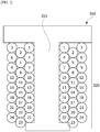
- FIG. 2 is a cross-sectional view of a tooth of a stator which illustrates a state of a coil that is wound around the tooth.
- a tooth 311 is disposed on the stator core 310.
- the coil 320 is wound a plurality of turns around the tooth 311.
- a number written in a circle which is a cross-section of the coil 320 refers to a turn number of the coil 320.
- the coil 320 is stacked on the tooth 311 to form a plurality of layers.
- the coil 320 may be wound twenty four turns around the tooth 311 to form three layers.
- the layer in contact with the tooth 311 is a first layer
- the layer stacked on the first layer is a second layer
- the layer stacked on the second layer is a third layer.
- the coil 320 may be wound around the tooth 311 such that the coil 320 of only (a ⁇ n+1) th turns among the plurality of turns forms the first layer closest to the tooth 311.
- the coil 320 of (a ⁇ n+x) th turns thereof may be wound around the tooth 311 to be disposed in an x th layer among the plurality of layers.
- the coil 320 of first, fourth, seventh, tenth, thirteenth, sixteenth, nineteenth, and twenty second turns of the coil 320 among the plurality of turns is wound to form the first layer in contact with the tooth 311.
- the coil 320 of second, fifth, eighth, eleventh, fourteenth, seventeenth, twentieth, and twenty third turns is wound to form the second layer stacked on the first layer.
- the coil 320 of third, sixth, ninth, twelfth, fifteenth, eighteenth, twenty first, and twenty fourth turns is wound to form the third layer stacked on the second layer.
- FIGS. 3 to 6 are cross-sectional views of the tooth of the stator which illustrate a process in which the coil is wound around the tooth.
- a winding process of the coil 320 will be specifically described below.
- the coil 320 of the first turn is wound to be in contact with the tooth 311 so as to form the first layer.
- the coil 320 of the second turn is wound to be stacked on the coil 320 of the first turn so as to form the second layer.
- the coil 320 of the third turn is wound to be stacked on the coil 320 of the second turn of the so as to form the third layer.
- the coil 320 of the fourth turn is wound to be in contact with the tooth 311 so as to form the first layer.
- the coil 320 of the fourth turn is disposed to be adjacent to the coil 320 of the first turn of in the same layer.
- the coil 320 of the fifth turn is wound to be stacked on the coil 320 of the fourth turn so as to form the second layer.
- the coil 320 of the fifth turn is disposed to be adjacent to the coil 320 of the second turn in the same layer.
- the coil 320 of the first, fourth, seventh, tenth, thirteenth, sixteenth, nineteenth, and twenty second turns is wound to form the first layer in contact with the tooth 311.
- the coil 320 of the second, fifth, eighth, eleventh, fourteenth, seventeenth, twentieth, and twenty third turns is wound to form the second layer.
- the coil 320 of the third, sixth, ninth, twelfth, fifteenth, eighteenth, twenty first, and twenty fourth turns is wound to form the third layer.
- the above described winding method of the coil 320 will be performed using an insulator which will be described below.
- FIG. 7 is a view illustrating the insulator 330 illustrated in FIG. 1
- FIG. 8 is a partial cross-sectional side view illustrating the insulator 330 illustrated in FIG. 7
- FIG. 9 is a front view illustrating the insulator illustrated in FIG. 7 .
- the insulator 330 may include a body portion 331, an inner guide 332, an outer guide 333, winding guide grooves 334, and winding guides 335.
- the body portion 331, the inner guide 332, the outer guides 333, and the winding guides 335 may only be separately described according to shapes and features thereof but are integrally formed to be connected to each other and form one single product.
- the body portion 331 surrounds the tooth 311.
- the coil 320 is wound around the body portion 331.
- the body portion 331 may include a first side surface portion 331a, a second side surface portion 331b, and a connecting portion 331c.
- An outer surface of the first side surface portion 331a and an outer surface of the second side surface portion 331b are regions around which the coil 320 is wound.
- an inner surface of the first side surface portion 331a and an inner surface of the second side surface portion 331b are regions in contact with the tooth 311.
- the connecting portion 331c connects an upper end portion of the first side surface portion 331a and an upper end portion of the second side surface portion 331b.
- a lower end portion of the first side surface portion 331a and a lower end portion of the second side surface portion 331b may be open.
- Two insulators 330 which are described above may be mounted on one tooth 311.
- the inner guide 332 may be disposed to extend upward from an inner side end of the body portion 331.
- the outer guide 333 may be disposed to extend upward from an outer side of the body portion 331.
- the winding guides 335 are disposed to protrude from a surface of the connecting portion 331c.
- the winding guides 335 may be plate members.
- the winding guides 335 may be disposed along the winding guide grooves 334 disposed in the connecting portion 331c.
- the winding guides 335 may be disposed between the winding guide grooves 334 which are adjacent to each other.
- the plurality of winding guides 335 may be disposed.
- a width w2 of the winding guide 335 is less than a width w1 of the connecting portion 331c.
- the width w1 of the connecting portion 331c is a horizontal length of the connecting portion 331c, which is a distance between boundaries with the first side surface portion 331a and the second side surface portion 331b.
- a height h3 of the winding guide 335 is less than a height h1 of the inner guide 332 and a height h2 of the outer guide 333.
- the height h3 of the winding guide 335 is a vertical height from the surface of the connecting portion 331c to an upper end of the winding guide 335.
- the height h1 of the inner guide 332 is a vertical height from the surface of the connecting portion 331c to an upper end of the inner guide 332.
- the height h2 of the outer guide 333 is a vertical height from the surface of the connecting portion 331c to an upper end of the outer guide 333.
- FIG. 10 is a view illustrating a winding guide which guides the coil during a winding process.
- the winding guides 335 guide the coil 320 to be stacked in the total layers.
- the coil 320 of the first turn is wound to be in contact with the tooth 311 to form the first layer
- the coil 320 of the second turn is directly stacked on the coil 320 which disposed in the first layer.
- the winding guide 335 guides the coil 320 of the second turn of to be stably stacked on the coil 320 of the first turn.
- the height h3 of the winding guide 335 may be less than a ⁇ D and greater than (a-1) ⁇ D.
- D is a diameter of a cross section of the coil 320.
- the height h3 of the winding guide 335 may not hinder a winding operation, and the coil 320 may be stably wound due to the height h3 of the winding guide 335.
- Such a winding method of the coil 320 is for reducing a blocking torque.
- the blocking torque is a maximum torque generated when a closed circuit is formed in a case in which a short circuit occurs in the coil 320.
- FIG. 11 is a graph showing blocking torque values according to the number of turns of a closed circuit
- FIG. 12 is a graph showing waveforms of blocking torques according to the number of turns of the closed circuit.
- the blocking torque increases.
- the number of turns in the closed circuit is seven, the blocking torque is 0.460 Nm at a speed of 800 rpm, but in a case in which the number of turns in the closed circuit is eight, the blocking torque increases to 0.517 Nm at a speed of 800 rpm.
- the number of turns in the closed circuit is a difference between turn numbers of coils of layers which are adjacent to each other and short-circuited.
- the number of turns in the closed circuit turn is seven which is eight minus one.
- the blocking torque increases to hinder rotation of the motor, and thus it is important to reduce the number of turns in the closed circuit.
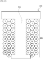
- FIG. 13 is a view illustrating a state of a coil that is short-circuited.
- the number of turns in the closed circuit is less than that in a closed circuit in a case in which a short circuit occurs through a general parallel winding method.
- the number of turns in the closed circuit is less than or equal to a+1.
- a difference between turn numbers of coils of layers adjacent to each other is large.
- a difference between turn numbers of the coils of the different layers corresponds to seven.
- a difference between turn numbers of the coils of the layers adjacent to each other is relatively small.
- a difference between turn numbers of the coils of the layers that is, the number of turns in a closed circuit is four, and is less than that in the closed circuit in the case of the general parallel winding method.
- the number of turns in the closed circuit is not greater than four
- such a winding method has an advantage of significantly reducing the blocking torque even when the parallel winding method is used.
Landscapes
- Engineering & Computer Science (AREA)
- Power Engineering (AREA)
- Manufacturing & Machinery (AREA)
- Chemical & Material Sciences (AREA)
- Combustion & Propulsion (AREA)
- Transportation (AREA)
- Mechanical Engineering (AREA)
- Windings For Motors And Generators (AREA)
- Insulation, Fastening Of Motor, Generator Windings (AREA)
Abstract
Description
- The present invention relates to a motor.
- An electric power steering system (EPS) is a system which secures turning stability of a vehicle and rapid restoring force so that a driver can stably drive. The EPS drives a motor to control operation of a steering shaft of the vehicle through an electronic control unit (ECU) according to travel conditions detected by a vehicle speed sensor, a torque angle sensor, and the like.
- The motor includes a stator and a rotor. The stator may include teeth forming a plurality of slots, and a coil is wound around each of the teeth. The coil is wound around the tooth to be stacked as a plurality of layers. In a case in which coils of the layers adjacent to each other are short-circuited, a closed circuit is generated so that a blocking torque is generated. The blocking torque hinders rotation of the motor so as to reduce performance of the motor. In this case, there is a problem in that, as a difference between turn numbers of the coils of the layers adjacent to each other increases, the blocking torque increases.
- The present invention is directed to providing a motor capable of reducing a blocking torque even using a parallel winding method.
- Objectives that should be solved according to embodiments are not limited to the above described objectives, and other objectives which are not described above will be clearly understood by those skilled in the art from the following specification.
- One aspect of the present invention provides a motor including a rotating shaft, a rotor coupled to the rotating shaft, and a stator disposed outside the rotor, wherein the stator includes a stator core having a plurality of teeth and a coil wound around each tooth of the teeth, the coil is wound a plurality of turns around the tooth, and only the coil of (a∗n+1)th turns among the plurality of turns forms a first layer closest to the tooth.
- In this case, a is the number of total stacked layers of the coil, and n is zero or a positive integer.
- The coil may be stacked as a plurality of layers on the tooth to and sequentially stacked from the first layer to an ath layer based on the first layer among the plurality of layers.
- The coil of (a∗n+x)th turns may be wound to be disposed as an x layer among the layers. In this case, a is the number of the total stacked layers of the coil, n is zero or a positive integer, and x is a positive integer less than or equal to a.
- The stator may include an insulator disposed on the tooth, the insulator may include a body portion surrounding the tooth, the body portion may include a first side surface portion and a second side surface portion which are in contact with both side surfaces of the tooth, and a connecting portion which connects the first side surface portion and the second side surface portion, and the connecting portion may include winding guides protruding from a surface of the connecting portion.
- The first side surface portion, the second side surface portion, and the connecting portion may include winding guide grooves concavely disposed in surfaces of the first side surface portion, the second side surface portion, and the connecting portion, and the plurality of winding guides may be disposed between the winding guide grooves disposed adjacent to each other.
- The body portion may include an inner side guide and an outer side guide, and a height from the surface of the connecting portion to an upper end of the winding guide may be less than a height of the inner side guide from the surface of the connecting portion and a height of the outer side guide from the surface of the connecting portion.
- A height of the coil guide may be less than a∗D and greater than (a-1)∗D. In this case, a is the number of total stacked layers of the coil, and D is a diameter of a cross section of the coil.
- A width of the winding guide may be less than a width of the connecting portion.
- In a case in which a short circuit occurs in the coil of the layers adjacent to each other and a closed circuit is formed, the number of turns in the closed circuit is less than a+1.
- According to embodiments, an advantageous effect is provided in that a difference between turn numbers of coils of layers adjacent to each other is decreased to decrease a blocking torque even when a parallel winding method is used and a short circuit occurs.
-
-
FIG. 1 is a view illustrating a motor according to an embodiment. -
FIG. 2 is a cross-sectional view of a tooth of a stator which illustrates a state of a coil that is wound around the tooth. -
FIGS. 3 to 6 are cross-sectional views of the tooth of the stator which illustrate a process in which the coil is wound around the tooth. -
FIG. 7 is a view illustrating an insulator illustrated inFIG. 1 . -
FIG. 8 is a partial cross-sectional side view illustrating the insulator illustrated inFIG. 7 . -
FIG. 9 is a front view illustrating the insulator illustrated inFIG. 7 . -
FIG. 10 is a view illustrating a winding guide which guides the coil during a winding process. -
FIG. 11 is a graph showing blocking torque values according to the number of turns of a closed circuit. -
FIG. 12 is a graph showing waveforms of blocking torques according to the number of turns of the closed circuit. -
FIG. 13 is a view illustrating a state of a coil that is short-circuited. - Hereinafter, exemplary embodiments of the present invention will be described in detail with reference to the accompanying drawings.
- However, the technical spirit of the present invention is not limited to some embodiments which will be described and may be realized using various other embodiments, and at least one component of the embodiments may be selectively coupled, substituted, and used to realize the technical spirit within the range of the technical spirit.
- In addition, unless clearly and specifically defined otherwise by context, all terms (including technical and scientific terms) used herein can be interpreted as having customary meanings to those skilled in the art, and meanings of generally used terms, such as those defined in commonly used dictionaries, will be interpreted by considering contextual meanings of the related technology.
- In addition, the terms used in the embodiments of the present invention are considered in a descriptive sense and not for limiting the present invention.
- In the present specification, unless clearly indicated otherwise by the context, singular forms include the plural forms thereof, and in a case in which "at least one (or one or more) among A, B, and C" is described, this may include at least one combination among all combinations which can be combined with A, B, and C.
- In descriptions of components of the present invention, terms such as "first," "second," "A," "B," "(a)," and "(b)" can be used.
- The terms are only to distinguish one element from another element, and an essence, order, and the like of the element are not limited by the terms.
- It should be understood that, when an element is referred to as being "connected or coupled" to another element, such a description may include both a case in which the element is directly connected or coupled to another element, and a case in which the element is connected or coupled to another element with still another element disposed therebetween.
- In a case in which any one element is described as being formed or disposed "on or under" another element, such a description includes both cases in which the two elements are formed or disposed to be in direct contact with each other and one or more other elements are interposed between the two elements. In addition, when one element is described as being disposed "on or under" another element, such a description may include a case in which the one element is disposed at an upper side or a lower side with respect to another element.
-
FIG. 1 is a view illustrating a motor according to an embodiment. - Referring to
FIG. 1 , the motor according to the embodiment may include a rotatingshaft 100, arotor 200, astator 300, and ahousing 400. - The rotating
shaft 100 may be coupled to therotor 200. When a current is supplied and an electromagnetic interaction occurs between therotor 200 and thestator 300, therotor 200 rotates and therotating shaft 100 rotates in conjunction with therotor 200. The rotatingshaft 100 may be connected to a steering shaft of a vehicle to transmit power to the steering shaft. - The
rotor 200 electrically interacts with thestator 300 and rotates. - The
rotor 200 may include a rotor core and magnets. The rotor core may be formed of a plurality of plates, which each have a thin circular steel plate shape and are stacked, or may have a cylindrical shape. A hole coupled to the rotatingshaft 100 may be formed at a center of the rotor core. A protrusion which guides the magnets may protrude from an outer circumferential surface of the rotor core. The magnets may be attached to the outer circumferential surface of the rotor core. The plurality of magnets may be disposed along a circumference of the rotor core at predetermined distances. Therotor 200 may include a can member which surrounds the magnets so that the magnets are fixed and not separated from the rotor core and are prevented from being exposed. - A coil may be wound around the
stator 300 to induce electrical interaction between thestator 300 and therotor 200. A specific structure of thestator 300 around which the coil is wound will be described below. Thestator 300 may include a stator core having a plurality of teeth. A ring-shaped yoke portion and the teeth around which the coil is wound from a yoke toward a center may be provided in the stator core. The teeth may be provided to be spaced a predetermined distance from each other along an outer circumferential surface of the yoke portion. Meanwhile, the stator core may be formed of a plurality of plates which each have a thin steel plate shape and are stacked on each other. In addition, a plurality of separate cores may be coupled or connected to each other to form the stator core. - The
housing 400 may accommodate therotor 200 and thestator 300 therein. Thehousing 400 has a cylindrical shape. In addition, an upper portion of thehousing 400 is open. The open upper portion of thehousing 400 is covered by a bracket. Thestator 300 is positioned inside thehousing 400, and therotor 200 may be disposed inside thestator 300. - A sensor configured to detect a magnetic force of a
sensing magnet 600 may be disposed on a printedcircuit board 500. In this case, the sensor may be a Hall integrated circuit (IC). The sensor detects changes of an N-pole and a P-pole of thesensing magnet 600 to generate a sensing signal. - The
sensing magnet 600 is coupled to therotating shaft 100 to operate in conjunction with therotor 200 so as to detect a position of therotor 200. -
FIG. 2 is a cross-sectional view of a tooth of a stator which illustrates a state of a coil that is wound around the tooth. - Referring to
FIG. 2 , atooth 311 is disposed on thestator core 310. Thecoil 320 is wound a plurality of turns around thetooth 311. InFIG. 2 , a number written in a circle which is a cross-section of thecoil 320 refers to a turn number of thecoil 320. Thecoil 320 is stacked on thetooth 311 to form a plurality of layers. For example, as illustrated inFIG. 2 , thecoil 320 may be wound twenty four turns around thetooth 311 to form three layers. Among the plurality of layers of thecoil 320, the layer in contact with thetooth 311 is a first layer, the layer stacked on the first layer is a second layer, and the layer stacked on the second layer is a third layer. - In this case, the
coil 320 may be wound around thetooth 311 such that thecoil 320 of only (a∗n+1)th turns among the plurality of turns forms the first layer closest to thetooth 311. In addition, thecoil 320 of (a∗n+x)th turns thereof may be wound around thetooth 311 to be disposed in an xth layer among the plurality of layers. - In this case, a is the number of total stacked layers of the coil 320 (for example, in the case of
FIG. 2 , a=3), n is zero or a positive integer, and x is a positive integer which is less than or equal to a. - For example, as illustrated in
FIG. 2 , thecoil 320 of first, fourth, seventh, tenth, thirteenth, sixteenth, nineteenth, and twenty second turns of thecoil 320 among the plurality of turns is wound to form the first layer in contact with thetooth 311. In addition, thecoil 320 of second, fifth, eighth, eleventh, fourteenth, seventeenth, twentieth, and twenty third turns is wound to form the second layer stacked on the first layer. In addition, thecoil 320 of third, sixth, ninth, twelfth, fifteenth, eighteenth, twenty first, and twenty fourth turns is wound to form the third layer stacked on the second layer. -
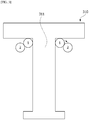
FIGS. 3 to 6 are cross-sectional views of the tooth of the stator which illustrate a process in which the coil is wound around the tooth. - A winding process of the
coil 320 will be specifically described below. - Referring to
FIG. 3 , first, thecoil 320 of the first turn is wound to be in contact with thetooth 311 so as to form the first layer. Next, thecoil 320 of the second turn is wound to be stacked on thecoil 320 of the first turn so as to form the second layer. - Referring to
FIG. 4 , next, thecoil 320 of the third turn is wound to be stacked on thecoil 320 of the second turn of the so as to form the third layer. - Referring to
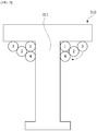
FIG. 5 , thecoil 320 of the fourth turn is wound to be in contact with thetooth 311 so as to form the first layer. Thecoil 320 of the fourth turn is disposed to be adjacent to thecoil 320 of the first turn of in the same layer. - Referring to
FIG. 6 , next, thecoil 320 of the fifth turn is wound to be stacked on thecoil 320 of the fourth turn so as to form the second layer. Thecoil 320 of the fifth turn is disposed to be adjacent to thecoil 320 of the second turn in the same layer. - When the winding process is performed as described above, as illustrated in
FIG. 2 , among the plurality of turns, thecoil 320 of the first, fourth, seventh, tenth, thirteenth, sixteenth, nineteenth, and twenty second turns is wound to form the first layer in contact with thetooth 311. In addition, thecoil 320 of the second, fifth, eighth, eleventh, fourteenth, seventeenth, twentieth, and twenty third turns is wound to form the second layer. In addition, thecoil 320 of the third, sixth, ninth, twelfth, fifteenth, eighteenth, twenty first, and twenty fourth turns is wound to form the third layer. - The above described winding method of the
coil 320 will be performed using an insulator which will be described below. -
FIG. 7 is a view illustrating theinsulator 330 illustrated inFIG. 1 ,FIG. 8 is a partial cross-sectional side view illustrating theinsulator 330 illustrated inFIG. 7 , andFIG. 9 is a front view illustrating the insulator illustrated inFIG. 7 . - Referring to
FIGS. 7 to 9 , theinsulator 330 may include abody portion 331, aninner guide 332, anouter guide 333, windingguide grooves 334, and windingguides 335. Thebody portion 331, theinner guide 332, theouter guides 333, and the windingguides 335 may only be separately described according to shapes and features thereof but are integrally formed to be connected to each other and form one single product. - The
body portion 331 surrounds thetooth 311. Thecoil 320 is wound around thebody portion 331. - The
body portion 331 may include a firstside surface portion 331a, a secondside surface portion 331b, and a connectingportion 331c. An outer surface of the firstside surface portion 331a and an outer surface of the secondside surface portion 331b are regions around which thecoil 320 is wound. In addition, an inner surface of the firstside surface portion 331a and an inner surface of the secondside surface portion 331b are regions in contact with thetooth 311. The connectingportion 331c connects an upper end portion of the firstside surface portion 331a and an upper end portion of the secondside surface portion 331b. A lower end portion of the firstside surface portion 331a and a lower end portion of the secondside surface portion 331b may be open. Twoinsulators 330 which are described above may be mounted on onetooth 311. - The
inner guide 332 may be disposed to extend upward from an inner side end of thebody portion 331. - The
outer guide 333 may be disposed to extend upward from an outer side of thebody portion 331. - The winding guides 335 are disposed to protrude from a surface of the connecting
portion 331c. The winding guides 335 may be plate members. The winding guides 335 may be disposed along the windingguide grooves 334 disposed in the connectingportion 331c. In addition, the windingguides 335 may be disposed between the windingguide grooves 334 which are adjacent to each other. In addition, the plurality of windingguides 335 may be disposed. - Meanwhile, referring to
FIG. 8 , a width w2 of the windingguide 335 is less than a width w1 of the connectingportion 331c. In this case, the width w1 of the connectingportion 331c is a horizontal length of the connectingportion 331c, which is a distance between boundaries with the firstside surface portion 331a and the secondside surface portion 331b. In addition, referring toFIG. 9 , a height h3 of the windingguide 335 is less than a height h1 of theinner guide 332 and a height h2 of theouter guide 333. In this case, the height h3 of the windingguide 335 is a vertical height from the surface of the connectingportion 331c to an upper end of the windingguide 335. In addition, the height h1 of theinner guide 332 is a vertical height from the surface of the connectingportion 331c to an upper end of theinner guide 332. In addition, the height h2 of theouter guide 333 is a vertical height from the surface of the connectingportion 331c to an upper end of theouter guide 333. -
FIG. 10 is a view illustrating a winding guide which guides the coil during a winding process. - Referring to
FIG. 10 , the windingguides 335 guide thecoil 320 to be stacked in the total layers. In the winding method for a motor according to the embodiment, after thecoil 320 of the first turn is wound to be in contact with thetooth 311 to form the first layer, thecoil 320 of the second turn is directly stacked on thecoil 320 which disposed in the first layer. In this case, the windingguide 335 guides thecoil 320 of the second turn of to be stably stacked on thecoil 320 of the first turn. - Meanwhile, the height h3 of the winding
guide 335 may be less than a∗D and greater than (a-1)∗D. In this case, a is the number of total stacked layers of the coil 320 (for example, a=3), and D is a diameter of a cross section of thecoil 320. The height h3 of the windingguide 335 may not hinder a winding operation, and thecoil 320 may be stably wound due to the height h3 of the windingguide 335. - Such a winding method of the
coil 320 is for reducing a blocking torque. The blocking torque is a maximum torque generated when a closed circuit is formed in a case in which a short circuit occurs in thecoil 320. -
FIG. 11 is a graph showing blocking torque values according to the number of turns of a closed circuit, andFIG. 12 is a graph showing waveforms of blocking torques according to the number of turns of the closed circuit. - Referring to
FIGS. 11 and12 , it may be seen that, as the number of turns in a closed circuit increases, the blocking torque increases. For example, it may be seen that, in a case in which the number of turns in the closed circuit is seven, the blocking torque is 0.460 Nm at a speed of 800 rpm, but in a case in which the number of turns in the closed circuit is eight, the blocking torque increases to 0.517 Nm at a speed of 800 rpm. In this case, the number of turns in the closed circuit is a difference between turn numbers of coils of layers which are adjacent to each other and short-circuited. For example, in a case in which the coil of the first turn in the first layer is short-circuited with the coil of the eighth turn in the second layer in a state in which the first and second layers are adjacent to each other, the number of turns in the closed circuit turn is seven which is eight minus one. - Accordingly, as the number of turns in the closed circuit increases, the blocking torque increases to hinder rotation of the motor, and thus it is important to reduce the number of turns in the closed circuit.
-
FIG. 13 is a view illustrating a state of a coil that is short-circuited. - Referring to
FIG. 13 , in the motor according to the embodiment, in a case in which a short circuit occurs in thecoil 320 of layers adjacent to each other, the number of turns in the closed circuit is less than that in a closed circuit in a case in which a short circuit occurs through a general parallel winding method. Specifically, in the motor according to the embodiment, in a case in which a short circuit occurs in thecoil 320 of layers adjacent to each other and the closed circuit is formed, the number of turns in the closed circuit is less than or equal to a+1. In this case, a is the number of total stacked layers of the coil 320 (for example, a=3). - For example, in the case of the parallel winding method through which, after a coil is completely wound to form a first layer, a second layer is stacked on the first layer and a third layer is stacked on the second layer, a difference between turn numbers of coils of layers adjacent to each other is large. For example, in a case in which a coil of a first turn in the first layer is short-circuited with the coil of an eighth turn in the second layer, a difference between turn numbers of the coils of the different layers, that is, the number of turns in a closed circuit, corresponds to seven.
- However, in the motor according to the embodiment, a difference between turn numbers of the coils of the layers adjacent to each other is relatively small. For example, when the coil of the twentieth turn in the second layer is short-circuited with the coil of the twenty fourth turn in the third layer, a difference between turn numbers of the coils of the layers, that is, the number of turns in a closed circuit is four, and is less than that in the closed circuit in the case of the general parallel winding method. In the case of
FIG. 13 , even when a short circuit occurs in the coil 32 of the layers, the number of turns in the closed circuit is not greater than four - Accordingly, such a winding method has an advantage of significantly reducing the blocking torque even when the parallel winding method is used.
- As described above, the motor according to one exemplary embodiment of the present invention has been specifically described with reference to the accompanying drawings.
- Therefore, the above-described embodiments should be considered in a descriptive sense only and not for purposes of limitation, and the scope of the present invention is defined by the appended claims and encompasses all modifications or alterations derived from meanings and the scope of the appended claims, and equivalents thereof.
Claims (9)
- A motor comprising:a rotating shaft;a rotor coupled to the rotating shaft; anda stator disposed outside the rotor,wherein the stator includes a stator core having a plurality of teeth and a coil wound around each tooth of the teeth,the coil is wound a plurality of turns around the tooth, andonly the coil of (a∗n+1)th turns among the plurality of turns forms a first layer closest to the tooth,wherein a is the number of total stacked layers of the coil, and n is zero or a positive integer.
- The motor of claim 1, wherein the coil is stacked as a plurality of layers on the tooth and sequentially stacked from the first layer to an ath layer based on the first layer among the plurality of layers.
- The motor of claim 1, wherein the coil of (a∗n+x)th turns is wound to be disposed as an x layer among the layers,
wherein a is the number of the total stacked layers of the coil, n is zero or a positive integer, and x is a positive integer less than or equal to a. - The motor of claim 1, wherein:the stator includes an insulator disposed on the tooth;the insulator includes a body portion surrounding the tooth;the body portion includes a first side surface portion and a second side surface portion which are in contact with both side surfaces of the tooth, and a connecting portion which connects the first side surface portion and the second side surface portion; andthe connecting portion includes winding guides protruding from a surface of the connecting portion.
- The motor of claim 4, wherein:the first side surface portion, the second side surface portion, and the connecting portion include winding guide grooves concavely disposed in surfaces of the first side surface portion, the second side surface portion, and the connecting portion; andthe winding guides are disposed between the winding guide grooves disposed adjacent to each other.
- The motor of claim 4, wherein:the body portion includes an inner side guide and an outer side guide; anda height from the surface of the connecting portion to an upper end of the winding guide is less than a height of the inner side guide from the surface of the connecting portion and a height of the outer side guide from the surface of the connecting portion.
- The motor of claim 6, wherein a height from the surface of the connecting portion to the upper end of the winding guide is less than a∗D and greater than (a-1)∗D,
wherein a is the number of total stacked layers of the coil, and D is a diameter of a cross section of the coil. - The motor of claim 4, wherein a width of the winding guide is less than a width of the connecting portion.
- The motor of claim 1, wherein, in a case in which a short circuit occurs in the coil of the layers adjacent to each other and a closed circuit is formed, the number of turns in the closed circuit is less than the a+1.
Applications Claiming Priority (2)
| Application Number | Priority Date | Filing Date | Title |
|---|---|---|---|
| KR1020170091583A KR102412390B1 (en) | 2017-07-19 | 2017-07-19 | Motor |
| PCT/KR2018/008142 WO2019017699A1 (en) | 2017-07-19 | 2018-07-19 | Motor |
Publications (3)
| Publication Number | Publication Date |
|---|---|
| EP3657644A1 true EP3657644A1 (en) | 2020-05-27 |
| EP3657644A4 EP3657644A4 (en) | 2021-03-31 |
| EP3657644B1 EP3657644B1 (en) | 2022-03-30 |
Family
ID=65015937
Family Applications (1)
| Application Number | Title | Priority Date | Filing Date |
|---|---|---|---|
| EP18835309.8A Active EP3657644B1 (en) | 2017-07-19 | 2018-07-19 | Motor |
Country Status (5)
| Country | Link |
|---|---|
| US (1) | US11398759B2 (en) |
| EP (1) | EP3657644B1 (en) |
| KR (1) | KR102412390B1 (en) |
| CN (1) | CN110945757B (en) |
| WO (1) | WO2019017699A1 (en) |
Families Citing this family (4)
| Publication number | Priority date | Publication date | Assignee | Title |
|---|---|---|---|---|
| US20220181940A1 (en) * | 2020-12-03 | 2022-06-09 | Joby Aero, Inc. | Redundant resolver |
| US20240113608A1 (en) * | 2022-10-03 | 2024-04-04 | LF Motor Co. | Lorentz force motor |
| JP2025127088A (en) * | 2024-02-20 | 2025-09-01 | ミネベアミツミ株式会社 | Stator and Motor |
| JP2025127089A (en) * | 2024-02-20 | 2025-09-01 | ミネベアミツミ株式会社 | Stator and Motor |
Family Cites Families (23)
| Publication number | Priority date | Publication date | Assignee | Title |
|---|---|---|---|---|
| WO2003105165A1 (en) * | 2002-06-11 | 2003-12-18 | 株式会社エス・エッチ・ティ | Air-core coil and manufacturing method thereof |
| JP2005110413A (en) * | 2003-09-30 | 2005-04-21 | Nissan Motor Co Ltd | Winding structure of electric motor |
| JP2005117751A (en) * | 2003-10-06 | 2005-04-28 | Chubu Electric Power Co Inc | Power storage flywheel device |
| CN1767319B (en) * | 2004-10-29 | 2010-09-29 | 株式会社日立制作所 | Rotating electric machine and manufacturing method thereof |
| EP1653587B1 (en) * | 2004-10-29 | 2013-06-26 | Hitachi, Ltd. | Rotating electrical machine and manufacturing method thereof |
| JP4527602B2 (en) * | 2005-05-30 | 2010-08-18 | 日立オートモティブシステムズ株式会社 | Method for manufacturing stator coil |
| DE102005037373B4 (en) * | 2005-08-08 | 2011-05-05 | Siemens Ag | Electric machine with a frontal deflection of electrical conductors |
| JP2007074841A (en) * | 2005-09-08 | 2007-03-22 | Toyota Motor Corp | Stator core, motor using the same, and method for manufacturing the same |
| JP2008278628A (en) * | 2007-04-27 | 2008-11-13 | Sumitomo Electric Ind Ltd | Split stator and split stator manufacturing method |
| JP2010220336A (en) * | 2009-03-16 | 2010-09-30 | Hitachi Automotive Systems Ltd | Rotating electric machine and manufacturing method of rotating electric machine |
| JP2011239535A (en) | 2010-05-07 | 2011-11-24 | Sumitomo Electric Ind Ltd | Coil, motor, and insulation material for core |
| JP2011239536A (en) | 2010-05-07 | 2011-11-24 | Sumitomo Electric Ind Ltd | Coil, motor, winding for coil, and winding method of winding |
| JP2014014196A (en) * | 2010-12-29 | 2014-01-23 | Nippon Densan Corp | Armature, insulator, and motor |
| JP5751927B2 (en) * | 2011-05-13 | 2015-07-22 | 三菱電機株式会社 | Rotating electric machine and method of manufacturing stator used therefor |
| JP5843156B2 (en) * | 2011-06-13 | 2016-01-13 | 日本電産株式会社 | Stator unit and motor |
| JP5619046B2 (en) * | 2012-02-10 | 2014-11-05 | 三菱電機株式会社 | Rotating electric machine and method of manufacturing stator used therefor |
| CN104137392B (en) * | 2012-06-21 | 2017-09-22 | 三菱电机株式会社 | rotating electrical machine |
| JP5963593B2 (en) | 2012-07-26 | 2016-08-03 | 日立オートモティブシステムズ株式会社 | Rotating electric machine |
| EP3065266B1 (en) * | 2013-10-30 | 2018-11-21 | Mitsubishi Electric Corporation | Electric motor, compressor equipped with same, and electric motor manufacturing method |
| KR102314212B1 (en) * | 2014-11-14 | 2021-10-18 | 현대모비스 주식회사 | bobbin for winding of flat cable |
| KR102410397B1 (en) * | 2015-06-30 | 2022-06-17 | 엘지이노텍 주식회사 | Insulator and Motor having the same |
| KR102500989B1 (en) * | 2015-11-12 | 2023-02-17 | 엘지이노텍 주식회사 | Insulator, stator and motor having the same |
| KR102512584B1 (en) * | 2015-12-15 | 2023-03-22 | 엘지이노텍 주식회사 | Insulator and motor including the same |
-
2017
- 2017-07-19 KR KR1020170091583A patent/KR102412390B1/en active Active
-
2018
- 2018-07-19 US US16/632,644 patent/US11398759B2/en active Active
- 2018-07-19 CN CN201880048160.XA patent/CN110945757B/en active Active
- 2018-07-19 WO PCT/KR2018/008142 patent/WO2019017699A1/en not_active Ceased
- 2018-07-19 EP EP18835309.8A patent/EP3657644B1/en active Active
Also Published As
| Publication number | Publication date |
|---|---|
| CN110945757B (en) | 2022-04-12 |
| KR102412390B1 (en) | 2022-06-23 |
| US11398759B2 (en) | 2022-07-26 |
| EP3657644A4 (en) | 2021-03-31 |
| KR20190009593A (en) | 2019-01-29 |
| EP3657644B1 (en) | 2022-03-30 |
| WO2019017699A1 (en) | 2019-01-24 |
| US20200169138A1 (en) | 2020-05-28 |
| CN110945757A (en) | 2020-03-31 |
Similar Documents
| Publication | Publication Date | Title |
|---|---|---|
| EP3509187B1 (en) | Stator, and motor comprising same | |
| CN102904388B (en) | Motor | |
| EP4009499B1 (en) | Motor, and motor-driven steering apparatus having same | |
| EP3734802B1 (en) | Stator and motor including same | |
| US11942823B2 (en) | Motor | |
| EP3657644B1 (en) | Motor | |
| US11901772B2 (en) | Rotating electrical machine | |
| US11130515B2 (en) | Cover assembly, motor and electric steering device including same | |
| US11362559B2 (en) | Motor | |
| US11431214B2 (en) | Rotor and motor comprising same | |
| US12166395B2 (en) | Motor | |
| US12261480B2 (en) | Motor | |
| KR102625434B1 (en) | Rotor and Motor having the same | |
| KR102477861B1 (en) | Motor and appartus for steering | |
| KR102566475B1 (en) | Motor | |
| US12328035B2 (en) | Motor having rotor structure with grooves to reduce cogging torque | |
| KR102446183B1 (en) | motor | |
| CN115811161A (en) | Stator and motor | |
| KR20190033823A (en) | Motor |
Legal Events
| Date | Code | Title | Description |
|---|---|---|---|
| STAA | Information on the status of an ep patent application or granted ep patent |
Free format text: STATUS: THE INTERNATIONAL PUBLICATION HAS BEEN MADE |
|
| PUAI | Public reference made under article 153(3) epc to a published international application that has entered the european phase |
Free format text: ORIGINAL CODE: 0009012 |
|
| STAA | Information on the status of an ep patent application or granted ep patent |
Free format text: STATUS: REQUEST FOR EXAMINATION WAS MADE |
|
| 17P | Request for examination filed |
Effective date: 20200117 |
|
| AK | Designated contracting states |
Kind code of ref document: A1 Designated state(s): AL AT BE BG CH CY CZ DE DK EE ES FI FR GB GR HR HU IE IS IT LI LT LU LV MC MK MT NL NO PL PT RO RS SE SI SK SM TR |
|
| AX | Request for extension of the european patent |
Extension state: BA ME |
|
| DAV | Request for validation of the european patent (deleted) | ||
| DAX | Request for extension of the european patent (deleted) | ||
| A4 | Supplementary search report drawn up and despatched |
Effective date: 20210303 |
|
| RIC1 | Information provided on ipc code assigned before grant |
Ipc: H02K 3/46 20060101ALI20210225BHEP Ipc: H02K 15/095 20060101ALI20210225BHEP Ipc: H02K 3/47 20060101ALI20210225BHEP Ipc: H02K 3/18 20060101AFI20210225BHEP Ipc: H02K 1/14 20060101ALI20210225BHEP Ipc: H01F 41/06 20160101ALI20210225BHEP Ipc: B62D 5/04 20060101ALI20210225BHEP Ipc: H02K 3/34 20060101ALI20210225BHEP |
|
| REG | Reference to a national code |
Ref country code: DE Ref legal event code: R079 Ref document number: 602018033129 Country of ref document: DE Free format text: PREVIOUS MAIN CLASS: H02K0003470000 Ipc: H01F0041064000 |
|
| GRAP | Despatch of communication of intention to grant a patent |
Free format text: ORIGINAL CODE: EPIDOSNIGR1 |
|
| STAA | Information on the status of an ep patent application or granted ep patent |
Free format text: STATUS: GRANT OF PATENT IS INTENDED |
|
| RIC1 | Information provided on ipc code assigned before grant |
Ipc: H02K 3/34 20060101ALN20210927BHEP Ipc: B62D 5/04 20060101ALI20210927BHEP Ipc: H02K 1/14 20060101ALI20210927BHEP Ipc: H02K 3/46 20060101ALI20210927BHEP Ipc: H02K 15/095 20060101ALI20210927BHEP Ipc: H02K 3/18 20060101ALI20210927BHEP Ipc: H01F 41/064 20160101AFI20210927BHEP |
|
| INTG | Intention to grant announced |
Effective date: 20211022 |
|
| RIC1 | Information provided on ipc code assigned before grant |
Ipc: H02K 3/34 20060101ALN20211011BHEP Ipc: B62D 5/04 20060101ALI20211011BHEP Ipc: H02K 1/14 20060101ALI20211011BHEP Ipc: H02K 3/46 20060101ALI20211011BHEP Ipc: H02K 15/095 20060101ALI20211011BHEP Ipc: H02K 3/18 20060101ALI20211011BHEP Ipc: H01F 41/064 20160101AFI20211011BHEP |
|
| GRAS | Grant fee paid |
Free format text: ORIGINAL CODE: EPIDOSNIGR3 |
|
| GRAA | (expected) grant |
Free format text: ORIGINAL CODE: 0009210 |
|
| STAA | Information on the status of an ep patent application or granted ep patent |
Free format text: STATUS: THE PATENT HAS BEEN GRANTED |
|
| AK | Designated contracting states |
Kind code of ref document: B1 Designated state(s): AL AT BE BG CH CY CZ DE DK EE ES FI FR GB GR HR HU IE IS IT LI LT LU LV MC MK MT NL NO PL PT RO RS SE SI SK SM TR |
|
| REG | Reference to a national code |
Ref country code: GB Ref legal event code: FG4D |
|
| REG | Reference to a national code |
Ref country code: CH Ref legal event code: EP |
|
| REG | Reference to a national code |
Ref country code: AT Ref legal event code: REF Ref document number: 1479953 Country of ref document: AT Kind code of ref document: T Effective date: 20220415 |
|
| REG | Reference to a national code |
Ref country code: DE Ref legal event code: R096 Ref document number: 602018033129 Country of ref document: DE |
|
| REG | Reference to a national code |
Ref country code: IE Ref legal event code: FG4D |
|
| REG | Reference to a national code |
Ref country code: NL Ref legal event code: FP |
|
| REG | Reference to a national code |
Ref country code: LT Ref legal event code: MG9D |
|
| PG25 | Lapsed in a contracting state [announced via postgrant information from national office to epo] |
Ref country code: SE Free format text: LAPSE BECAUSE OF FAILURE TO SUBMIT A TRANSLATION OF THE DESCRIPTION OR TO PAY THE FEE WITHIN THE PRESCRIBED TIME-LIMIT Effective date: 20220330 Ref country code: RS Free format text: LAPSE BECAUSE OF FAILURE TO SUBMIT A TRANSLATION OF THE DESCRIPTION OR TO PAY THE FEE WITHIN THE PRESCRIBED TIME-LIMIT Effective date: 20220330 Ref country code: NO Free format text: LAPSE BECAUSE OF FAILURE TO SUBMIT A TRANSLATION OF THE DESCRIPTION OR TO PAY THE FEE WITHIN THE PRESCRIBED TIME-LIMIT Effective date: 20220630 Ref country code: LT Free format text: LAPSE BECAUSE OF FAILURE TO SUBMIT A TRANSLATION OF THE DESCRIPTION OR TO PAY THE FEE WITHIN THE PRESCRIBED TIME-LIMIT Effective date: 20220330 Ref country code: HR Free format text: LAPSE BECAUSE OF FAILURE TO SUBMIT A TRANSLATION OF THE DESCRIPTION OR TO PAY THE FEE WITHIN THE PRESCRIBED TIME-LIMIT Effective date: 20220330 Ref country code: BG Free format text: LAPSE BECAUSE OF FAILURE TO SUBMIT A TRANSLATION OF THE DESCRIPTION OR TO PAY THE FEE WITHIN THE PRESCRIBED TIME-LIMIT Effective date: 20220630 |
|
| REG | Reference to a national code |
Ref country code: AT Ref legal event code: MK05 Ref document number: 1479953 Country of ref document: AT Kind code of ref document: T Effective date: 20220330 |
|
| PG25 | Lapsed in a contracting state [announced via postgrant information from national office to epo] |
Ref country code: LV Free format text: LAPSE BECAUSE OF FAILURE TO SUBMIT A TRANSLATION OF THE DESCRIPTION OR TO PAY THE FEE WITHIN THE PRESCRIBED TIME-LIMIT Effective date: 20220330 Ref country code: GR Free format text: LAPSE BECAUSE OF FAILURE TO SUBMIT A TRANSLATION OF THE DESCRIPTION OR TO PAY THE FEE WITHIN THE PRESCRIBED TIME-LIMIT Effective date: 20220701 Ref country code: FI Free format text: LAPSE BECAUSE OF FAILURE TO SUBMIT A TRANSLATION OF THE DESCRIPTION OR TO PAY THE FEE WITHIN THE PRESCRIBED TIME-LIMIT Effective date: 20220330 |
|
| PG25 | Lapsed in a contracting state [announced via postgrant information from national office to epo] |
Ref country code: SM Free format text: LAPSE BECAUSE OF FAILURE TO SUBMIT A TRANSLATION OF THE DESCRIPTION OR TO PAY THE FEE WITHIN THE PRESCRIBED TIME-LIMIT Effective date: 20220330 Ref country code: SK Free format text: LAPSE BECAUSE OF FAILURE TO SUBMIT A TRANSLATION OF THE DESCRIPTION OR TO PAY THE FEE WITHIN THE PRESCRIBED TIME-LIMIT Effective date: 20220330 Ref country code: RO Free format text: LAPSE BECAUSE OF FAILURE TO SUBMIT A TRANSLATION OF THE DESCRIPTION OR TO PAY THE FEE WITHIN THE PRESCRIBED TIME-LIMIT Effective date: 20220330 Ref country code: PT Free format text: LAPSE BECAUSE OF FAILURE TO SUBMIT A TRANSLATION OF THE DESCRIPTION OR TO PAY THE FEE WITHIN THE PRESCRIBED TIME-LIMIT Effective date: 20220801 Ref country code: ES Free format text: LAPSE BECAUSE OF FAILURE TO SUBMIT A TRANSLATION OF THE DESCRIPTION OR TO PAY THE FEE WITHIN THE PRESCRIBED TIME-LIMIT Effective date: 20220330 Ref country code: EE Free format text: LAPSE BECAUSE OF FAILURE TO SUBMIT A TRANSLATION OF THE DESCRIPTION OR TO PAY THE FEE WITHIN THE PRESCRIBED TIME-LIMIT Effective date: 20220330 Ref country code: CZ Free format text: LAPSE BECAUSE OF FAILURE TO SUBMIT A TRANSLATION OF THE DESCRIPTION OR TO PAY THE FEE WITHIN THE PRESCRIBED TIME-LIMIT Effective date: 20220330 Ref country code: AT Free format text: LAPSE BECAUSE OF FAILURE TO SUBMIT A TRANSLATION OF THE DESCRIPTION OR TO PAY THE FEE WITHIN THE PRESCRIBED TIME-LIMIT Effective date: 20220330 |
|
| PG25 | Lapsed in a contracting state [announced via postgrant information from national office to epo] |
Ref country code: PL Free format text: LAPSE BECAUSE OF FAILURE TO SUBMIT A TRANSLATION OF THE DESCRIPTION OR TO PAY THE FEE WITHIN THE PRESCRIBED TIME-LIMIT Effective date: 20220330 Ref country code: IS Free format text: LAPSE BECAUSE OF FAILURE TO SUBMIT A TRANSLATION OF THE DESCRIPTION OR TO PAY THE FEE WITHIN THE PRESCRIBED TIME-LIMIT Effective date: 20220730 Ref country code: AL Free format text: LAPSE BECAUSE OF FAILURE TO SUBMIT A TRANSLATION OF THE DESCRIPTION OR TO PAY THE FEE WITHIN THE PRESCRIBED TIME-LIMIT Effective date: 20220330 |
|
| REG | Reference to a national code |
Ref country code: DE Ref legal event code: R097 Ref document number: 602018033129 Country of ref document: DE |
|
| PG25 | Lapsed in a contracting state [announced via postgrant information from national office to epo] |
Ref country code: DK Free format text: LAPSE BECAUSE OF FAILURE TO SUBMIT A TRANSLATION OF THE DESCRIPTION OR TO PAY THE FEE WITHIN THE PRESCRIBED TIME-LIMIT Effective date: 20220330 |
|
| PLBE | No opposition filed within time limit |
Free format text: ORIGINAL CODE: 0009261 |
|
| STAA | Information on the status of an ep patent application or granted ep patent |
Free format text: STATUS: NO OPPOSITION FILED WITHIN TIME LIMIT |
|
| PG25 | Lapsed in a contracting state [announced via postgrant information from national office to epo] |
Ref country code: MC Free format text: LAPSE BECAUSE OF FAILURE TO SUBMIT A TRANSLATION OF THE DESCRIPTION OR TO PAY THE FEE WITHIN THE PRESCRIBED TIME-LIMIT Effective date: 20220330 |
|
| REG | Reference to a national code |
Ref country code: CH Ref legal event code: PL |
|
| 26N | No opposition filed |
Effective date: 20230103 |
|
| GBPC | Gb: european patent ceased through non-payment of renewal fee |
Effective date: 20220719 |
|
| REG | Reference to a national code |
Ref country code: BE Ref legal event code: MM Effective date: 20220731 |
|
| PG25 | Lapsed in a contracting state [announced via postgrant information from national office to epo] |
Ref country code: LU Free format text: LAPSE BECAUSE OF NON-PAYMENT OF DUE FEES Effective date: 20220719 Ref country code: LI Free format text: LAPSE BECAUSE OF NON-PAYMENT OF DUE FEES Effective date: 20220731 Ref country code: CH Free format text: LAPSE BECAUSE OF NON-PAYMENT OF DUE FEES Effective date: 20220731 |
|
| PG25 | Lapsed in a contracting state [announced via postgrant information from national office to epo] |
Ref country code: SI Free format text: LAPSE BECAUSE OF FAILURE TO SUBMIT A TRANSLATION OF THE DESCRIPTION OR TO PAY THE FEE WITHIN THE PRESCRIBED TIME-LIMIT Effective date: 20220330 Ref country code: GB Free format text: LAPSE BECAUSE OF NON-PAYMENT OF DUE FEES Effective date: 20220719 Ref country code: BE Free format text: LAPSE BECAUSE OF NON-PAYMENT OF DUE FEES Effective date: 20220731 |
|
| PG25 | Lapsed in a contracting state [announced via postgrant information from national office to epo] |
Ref country code: IT Free format text: LAPSE BECAUSE OF FAILURE TO SUBMIT A TRANSLATION OF THE DESCRIPTION OR TO PAY THE FEE WITHIN THE PRESCRIBED TIME-LIMIT Effective date: 20220330 Ref country code: IE Free format text: LAPSE BECAUSE OF NON-PAYMENT OF DUE FEES Effective date: 20220719 |
|
| PG25 | Lapsed in a contracting state [announced via postgrant information from national office to epo] |
Ref country code: MK Free format text: LAPSE BECAUSE OF FAILURE TO SUBMIT A TRANSLATION OF THE DESCRIPTION OR TO PAY THE FEE WITHIN THE PRESCRIBED TIME-LIMIT Effective date: 20220330 Ref country code: CY Free format text: LAPSE BECAUSE OF FAILURE TO SUBMIT A TRANSLATION OF THE DESCRIPTION OR TO PAY THE FEE WITHIN THE PRESCRIBED TIME-LIMIT Effective date: 20220330 |
|
| PG25 | Lapsed in a contracting state [announced via postgrant information from national office to epo] |
Ref country code: HU Free format text: LAPSE BECAUSE OF FAILURE TO SUBMIT A TRANSLATION OF THE DESCRIPTION OR TO PAY THE FEE WITHIN THE PRESCRIBED TIME-LIMIT; INVALID AB INITIO Effective date: 20180719 |
|
| PG25 | Lapsed in a contracting state [announced via postgrant information from national office to epo] |
Ref country code: TR Free format text: LAPSE BECAUSE OF FAILURE TO SUBMIT A TRANSLATION OF THE DESCRIPTION OR TO PAY THE FEE WITHIN THE PRESCRIBED TIME-LIMIT Effective date: 20220330 |
|
| PG25 | Lapsed in a contracting state [announced via postgrant information from national office to epo] |
Ref country code: MT Free format text: LAPSE BECAUSE OF FAILURE TO SUBMIT A TRANSLATION OF THE DESCRIPTION OR TO PAY THE FEE WITHIN THE PRESCRIBED TIME-LIMIT Effective date: 20220330 |
|
| REG | Reference to a national code |
Ref country code: DE Ref legal event code: R082 Ref document number: 602018033129 Country of ref document: DE Representative=s name: PLASSERAUD IP GMBH, DE |
|
| PGFP | Annual fee paid to national office [announced via postgrant information from national office to epo] |
Ref country code: NL Payment date: 20250623 Year of fee payment: 8 |
|
| PGFP | Annual fee paid to national office [announced via postgrant information from national office to epo] |
Ref country code: FR Payment date: 20250624 Year of fee payment: 8 |
|
| PGFP | Annual fee paid to national office [announced via postgrant information from national office to epo] |
Ref country code: DE Payment date: 20250624 Year of fee payment: 8 |