EP3657266B1 - Vorrichtung und verfahren zum erzeugen eines hologramms - Google Patents
Vorrichtung und verfahren zum erzeugen eines hologramms Download PDFInfo
- Publication number
- EP3657266B1 EP3657266B1 EP19210758.9A EP19210758A EP3657266B1 EP 3657266 B1 EP3657266 B1 EP 3657266B1 EP 19210758 A EP19210758 A EP 19210758A EP 3657266 B1 EP3657266 B1 EP 3657266B1
- Authority
- EP
- European Patent Office
- Prior art keywords
- hologram
- laser radiation
- optical element
- diffractive optical
- recording material
- Prior art date
- Legal status (The legal status is an assumption and is not a legal conclusion. Google has not performed a legal analysis and makes no representation as to the accuracy of the status listed.)
- Active
Links
Images

Classifications
-
- G—PHYSICS
- G03—PHOTOGRAPHY; CINEMATOGRAPHY; ANALOGOUS TECHNIQUES USING WAVES OTHER THAN OPTICAL WAVES; ELECTROGRAPHY; HOLOGRAPHY
- G03H—HOLOGRAPHIC PROCESSES OR APPARATUS
- G03H1/00—Holographic processes or apparatus using light, infrared or ultraviolet waves for obtaining holograms or for obtaining an image from them; Details peculiar thereto
- G03H1/04—Processes or apparatus for producing holograms
- G03H1/0402—Recording geometries or arrangements
-
- B—PERFORMING OPERATIONS; TRANSPORTING
- B42—BOOKBINDING; ALBUMS; FILES; SPECIAL PRINTED MATTER
- B42D—BOOKS; BOOK COVERS; LOOSE LEAVES; PRINTED MATTER CHARACTERISED BY IDENTIFICATION OR SECURITY FEATURES; PRINTED MATTER OF SPECIAL FORMAT OR STYLE NOT OTHERWISE PROVIDED FOR; DEVICES FOR USE THEREWITH AND NOT OTHERWISE PROVIDED FOR; MOVABLE-STRIP WRITING OR READING APPARATUS
- B42D25/00—Information-bearing cards or sheet-like structures characterised by identification or security features; Manufacture thereof
- B42D25/30—Identification or security features, e.g. for preventing forgery
- B42D25/328—Diffraction gratings; Holograms
-
- B—PERFORMING OPERATIONS; TRANSPORTING
- B42—BOOKBINDING; ALBUMS; FILES; SPECIAL PRINTED MATTER
- B42D—BOOKS; BOOK COVERS; LOOSE LEAVES; PRINTED MATTER CHARACTERISED BY IDENTIFICATION OR SECURITY FEATURES; PRINTED MATTER OF SPECIAL FORMAT OR STYLE NOT OTHERWISE PROVIDED FOR; DEVICES FOR USE THEREWITH AND NOT OTHERWISE PROVIDED FOR; MOVABLE-STRIP WRITING OR READING APPARATUS
- B42D25/00—Information-bearing cards or sheet-like structures characterised by identification or security features; Manufacture thereof
- B42D25/40—Manufacture
- B42D25/405—Marking
- B42D25/41—Marking using electromagnetic radiation
-
- G—PHYSICS
- G03—PHOTOGRAPHY; CINEMATOGRAPHY; ANALOGOUS TECHNIQUES USING WAVES OTHER THAN OPTICAL WAVES; ELECTROGRAPHY; HOLOGRAPHY
- G03H—HOLOGRAPHIC PROCESSES OR APPARATUS
- G03H1/00—Holographic processes or apparatus using light, infrared or ultraviolet waves for obtaining holograms or for obtaining an image from them; Details peculiar thereto
- G03H1/04—Processes or apparatus for producing holograms
- G03H1/10—Processes or apparatus for producing holograms using modulated reference beam
-
- G—PHYSICS
- G03—PHOTOGRAPHY; CINEMATOGRAPHY; ANALOGOUS TECHNIQUES USING WAVES OTHER THAN OPTICAL WAVES; ELECTROGRAPHY; HOLOGRAPHY
- G03H—HOLOGRAPHIC PROCESSES OR APPARATUS
- G03H1/00—Holographic processes or apparatus using light, infrared or ultraviolet waves for obtaining holograms or for obtaining an image from them; Details peculiar thereto
- G03H1/04—Processes or apparatus for producing holograms
- G03H1/20—Copying holograms by holographic, i.e. optical means
- G03H1/202—Contact copy when the reconstruction beam for the master H1 also serves as reference beam for the copy H2
-
- G—PHYSICS
- G03—PHOTOGRAPHY; CINEMATOGRAPHY; ANALOGOUS TECHNIQUES USING WAVES OTHER THAN OPTICAL WAVES; ELECTROGRAPHY; HOLOGRAPHY
- G03H—HOLOGRAPHIC PROCESSES OR APPARATUS
- G03H1/00—Holographic processes or apparatus using light, infrared or ultraviolet waves for obtaining holograms or for obtaining an image from them; Details peculiar thereto
- G03H1/26—Processes or apparatus specially adapted to produce multiple sub- holograms or to obtain images from them, e.g. multicolour technique
- G03H1/30—Processes or apparatus specially adapted to produce multiple sub- holograms or to obtain images from them, e.g. multicolour technique discrete holograms only
-
- G—PHYSICS
- G03—PHOTOGRAPHY; CINEMATOGRAPHY; ANALOGOUS TECHNIQUES USING WAVES OTHER THAN OPTICAL WAVES; ELECTROGRAPHY; HOLOGRAPHY
- G03H—HOLOGRAPHIC PROCESSES OR APPARATUS
- G03H1/00—Holographic processes or apparatus using light, infrared or ultraviolet waves for obtaining holograms or for obtaining an image from them; Details peculiar thereto
- G03H1/0005—Adaptation of holography to specific applications
- G03H1/0011—Adaptation of holography to specific applications for security or authentication
-
- G—PHYSICS
- G03—PHOTOGRAPHY; CINEMATOGRAPHY; ANALOGOUS TECHNIQUES USING WAVES OTHER THAN OPTICAL WAVES; ELECTROGRAPHY; HOLOGRAPHY
- G03H—HOLOGRAPHIC PROCESSES OR APPARATUS
- G03H1/00—Holographic processes or apparatus using light, infrared or ultraviolet waves for obtaining holograms or for obtaining an image from them; Details peculiar thereto
- G03H1/04—Processes or apparatus for producing holograms
- G03H1/0402—Recording geometries or arrangements
- G03H1/0406—Image plane or focused image holograms, i.e. an image of the object or holobject is formed on, in or across the recording plane
-
- G—PHYSICS
- G03—PHOTOGRAPHY; CINEMATOGRAPHY; ANALOGOUS TECHNIQUES USING WAVES OTHER THAN OPTICAL WAVES; ELECTROGRAPHY; HOLOGRAPHY
- G03H—HOLOGRAPHIC PROCESSES OR APPARATUS
- G03H1/00—Holographic processes or apparatus using light, infrared or ultraviolet waves for obtaining holograms or for obtaining an image from them; Details peculiar thereto
- G03H1/26—Processes or apparatus specially adapted to produce multiple sub- holograms or to obtain images from them, e.g. multicolour technique
- G03H1/2645—Multiplexing processes, e.g. aperture, shift, or wavefront multiplexing
-
- G—PHYSICS
- G03—PHOTOGRAPHY; CINEMATOGRAPHY; ANALOGOUS TECHNIQUES USING WAVES OTHER THAN OPTICAL WAVES; ELECTROGRAPHY; HOLOGRAPHY
- G03H—HOLOGRAPHIC PROCESSES OR APPARATUS
- G03H1/00—Holographic processes or apparatus using light, infrared or ultraviolet waves for obtaining holograms or for obtaining an image from them; Details peculiar thereto
- G03H1/02—Details of features involved during the holographic process; Replication of holograms without interference recording
- G03H2001/0208—Individual components other than the hologram
- G03H2001/0216—Optical components
-
- G—PHYSICS
- G03—PHOTOGRAPHY; CINEMATOGRAPHY; ANALOGOUS TECHNIQUES USING WAVES OTHER THAN OPTICAL WAVES; ELECTROGRAPHY; HOLOGRAPHY
- G03H—HOLOGRAPHIC PROCESSES OR APPARATUS
- G03H1/00—Holographic processes or apparatus using light, infrared or ultraviolet waves for obtaining holograms or for obtaining an image from them; Details peculiar thereto
- G03H1/02—Details of features involved during the holographic process; Replication of holograms without interference recording
- G03H2001/0208—Individual components other than the hologram
- G03H2001/0224—Active addressable light modulator, i.e. Spatial Light Modulator [SLM]
-
- G—PHYSICS
- G03—PHOTOGRAPHY; CINEMATOGRAPHY; ANALOGOUS TECHNIQUES USING WAVES OTHER THAN OPTICAL WAVES; ELECTROGRAPHY; HOLOGRAPHY
- G03H—HOLOGRAPHIC PROCESSES OR APPARATUS
- G03H1/00—Holographic processes or apparatus using light, infrared or ultraviolet waves for obtaining holograms or for obtaining an image from them; Details peculiar thereto
- G03H1/04—Processes or apparatus for producing holograms
- G03H1/0465—Particular recording light; Beam shape or geometry
- G03H2001/0473—Particular illumination angle between object or reference beams and hologram
-
- G—PHYSICS
- G03—PHOTOGRAPHY; CINEMATOGRAPHY; ANALOGOUS TECHNIQUES USING WAVES OTHER THAN OPTICAL WAVES; ELECTROGRAPHY; HOLOGRAPHY
- G03H—HOLOGRAPHIC PROCESSES OR APPARATUS
- G03H2210/00—Object characteristics
- G03H2210/20—2D object
- G03H2210/22—2D SLM object wherein the object beam is formed of the light modulated by the SLM
-
- G—PHYSICS
- G03—PHOTOGRAPHY; CINEMATOGRAPHY; ANALOGOUS TECHNIQUES USING WAVES OTHER THAN OPTICAL WAVES; ELECTROGRAPHY; HOLOGRAPHY
- G03H—HOLOGRAPHIC PROCESSES OR APPARATUS
- G03H2222/00—Light sources or light beam properties
- G03H2222/40—Particular irradiation beam not otherwise provided for
- G03H2222/42—Reference beam at recording stage
-
- G—PHYSICS
- G03—PHOTOGRAPHY; CINEMATOGRAPHY; ANALOGOUS TECHNIQUES USING WAVES OTHER THAN OPTICAL WAVES; ELECTROGRAPHY; HOLOGRAPHY
- G03H—HOLOGRAPHIC PROCESSES OR APPARATUS
- G03H2223/00—Optical components
- G03H2223/13—Phase mask
-
- G—PHYSICS
- G03—PHOTOGRAPHY; CINEMATOGRAPHY; ANALOGOUS TECHNIQUES USING WAVES OTHER THAN OPTICAL WAVES; ELECTROGRAPHY; HOLOGRAPHY
- G03H—HOLOGRAPHIC PROCESSES OR APPARATUS
- G03H2223/00—Optical components
- G03H2223/17—Element having optical power
-
- G—PHYSICS
- G03—PHOTOGRAPHY; CINEMATOGRAPHY; ANALOGOUS TECHNIQUES USING WAVES OTHER THAN OPTICAL WAVES; ELECTROGRAPHY; HOLOGRAPHY
- G03H—HOLOGRAPHIC PROCESSES OR APPARATUS
- G03H2223/00—Optical components
- G03H2223/23—Diffractive element
-
- G—PHYSICS
- G03—PHOTOGRAPHY; CINEMATOGRAPHY; ANALOGOUS TECHNIQUES USING WAVES OTHER THAN OPTICAL WAVES; ELECTROGRAPHY; HOLOGRAPHY
- G03H—HOLOGRAPHIC PROCESSES OR APPARATUS
- G03H2223/00—Optical components
- G03H2223/24—Reflector; Mirror
-
- G—PHYSICS
- G03—PHOTOGRAPHY; CINEMATOGRAPHY; ANALOGOUS TECHNIQUES USING WAVES OTHER THAN OPTICAL WAVES; ELECTROGRAPHY; HOLOGRAPHY
- G03H—HOLOGRAPHIC PROCESSES OR APPARATUS
- G03H2223/00—Optical components
- G03H2223/50—Particular location or purpose of optical element
-
- G—PHYSICS
- G03—PHOTOGRAPHY; CINEMATOGRAPHY; ANALOGOUS TECHNIQUES USING WAVES OTHER THAN OPTICAL WAVES; ELECTROGRAPHY; HOLOGRAPHY
- G03H—HOLOGRAPHIC PROCESSES OR APPARATUS
- G03H2225/00—Active addressable light modulator
- G03H2225/10—Shape or geometry
- G03H2225/12—2D SLM
-
- G—PHYSICS
- G03—PHOTOGRAPHY; CINEMATOGRAPHY; ANALOGOUS TECHNIQUES USING WAVES OTHER THAN OPTICAL WAVES; ELECTROGRAPHY; HOLOGRAPHY
- G03H—HOLOGRAPHIC PROCESSES OR APPARATUS
- G03H2227/00—Mechanical components or mechanical aspects not otherwise provided for
- G03H2227/04—Production line for mass production
Definitions
- the invention relates to a device and a method for producing a hologram with a hologram master, in particular in contact copying.
- Holograms are used as security elements to protect valuable or security documents.
- the holograms make counterfeiting or imitation of the value or security document more difficult and thereby increase its security.
- holograms In order to also be able to use holograms as security features in the mass production of value or security documents, holograms must be produced, in particular copied, in an efficient manner during the production of the value or security documents.
- a hologram master to be copied is produced in the form of a master hologram in which the holographic information is stored.
- a holographic recording material to be exposed for example a hologram film made from a photopolymer, is then arranged areally on the hologram master. If the hologram master is irradiated with the appropriate laser radiation, the hologram stored in the hologram master is reconstructed and exposed into the hologram film, ie copied into it.
- a corresponding device and a corresponding method are for example in EP 0 896 260 A2 described.
- a laser beam is brought to a line-shaped profile by means of a Powell lens.
- the laser radiation formed in this way is then guided onto the holographic recording material and the hologram master by means of a lens.
- the linear laser radiation is guided ("scanned") step by step over the hologram master and the holographic recording material by means of a rotatable mirror of a scanner arranged in the beam path.
- the method described is complex and slow, since stepwise exposure of the area to be copied is always necessary. Furthermore, the method is expensive and error-prone due to a large number of optical components.
- the invention is based on the object of creating a device and a method for generating a hologram, in which the generation can be carried out in an improved manner.
- phase mask includes a phase modulation layer that modulates a phase of different parts of the incident light differently so that a different optical phase retardation in a range between 0 and 2pi is imparted to different parts of the incident light.
- a hologram recording device includes a light source; a signal beam optical system that divides a beam emitted from the light source into a reference beam and a signal beam, modulates the signal beam according to the hologram pixel information, and irradiates the signal beam onto a hologram recording medium.
- the signal beam optical system includes the phase mask.
- the hologram recording device also includes a reference beam optical system that irradiates the reference beam onto the hologram recording medium.
- the method for producing a master hologram comprises the steps of: arranging a diffuse scatterer, an aperture, a Fourier lens and a holographic recording material on an optical arrangement axis such that an optical axis of the Fourier lens, a surface normal of the holographic recording material and a surface normal of an aperture plane of the aperture are collinear with the optical assembly axis, wherein the aperture is placed between the diffuse scatterer and the Fourier lens immediately adjacent to the diffuse scatterer and the diffuse scatterer is placed in a focal plane of the Fourier lens and coherent first light is irradiated onto the diffuse scatterer becomes, in order to thereby generate the diffusely scattered light, which is limited by means of the aperture and guided by means of the Fourier lens into the holographic recording material as object light and second coherent light coherent with the first coherent light from a side facing away from the Fourier lens into the holographic recording material is irradiated as reference light to form a reflection volume hologram in the holographic recording material.
- the document also discloses the use of
- an individualization device which is designed to receive light from a light source from a reception direction and to output spatially modulated light in an output direction for a hologram exposure, comprising a spatial light modulator and beam guiding optics in order to guide the light from the light source onto the spatial light modulator and guiding away the light modulated by the spatial light modulator, wherein a surface normal of the spatial light modulator is tilted at least with respect to a surface normal of a first interface of a component of the beam guiding optics through which the modulated light passes after modulation at the spatial light modulator.
- an exposure device for holograms which includes such an individualization device.
- Diffractive phase elements for beam shaping a new design method, Applied Optics, Optical Society of America, Washington DC, USA, Vol. 34, No. 8, March 10, 1995, pp. 1314-1320 , ISSN: 0003-6935 , Diffractive phase elements for beam shaping are known.
- documents of value or security Items that have at least one security feature are referred to as documents of value or security.
- security documents are: identity cards, passports, ID cards, access control cards, visas, tax stamps, tickets, driver's licenses, Vehicle papers, documents of value such as banknotes, cheques, postage stamps, credit cards, any chip cards and adhesive labels (e.g. for product security).
- An optical element is referred to as a diffractive optical element, which comprises an optical grating and carries out a beam shaping using diffraction effects on this optical grating.
- a diffractive optical element is a glass substrate on whose surfaces microstructures are applied, which form the optical lattice. Due to the microstructures, individual partial beams have different path lengths, resulting in phase modulations that can lead to interference patterns. An amplitude is additionally modulated by constructive and destructive superimposition.
- a laser radiation transmitted through the diffractive optical element can be changed and adjusted in its form and in its intensity by specifically forming the microstructures, in particular with reference to a focal plane.
- the optically effective microstructures can be produced by modulating the refractive index and/or by modulating a height profile of the surface.
- holographic recording material any material that is suitable for imprinting a volume hologram on it is referred to as holographic recording material.
- a holographic recording material can be a hologram film.
- Hologram films produced on a photopolymer basis are particularly suitable.
- hologram films made on a silver halide basis can also be used, in particular bleached silver halide films.
- Other materials are dichromated gelatin or photorefractive crystals.
- the holographic recording material or a hologram master or master hologram is designed to be smooth and planar. Minor deviations to eliminate imaging errors or the like are not affected by this.
- a hologram master is a sample from which a hologram is made. Such a hologram master can be a master hologram, a mirror or a grating, for example.
- a master hologram is a hologram master designed as a hologram.
- a focusing screen serves as a hologram master.
- the volume reflection hologram produced from this in a contact copy represents a master hologram which can be used as a hologram master in the contact copy process for the production of individualized security elements.
- this master hologram is then also the hologram master for the individually produced security elements, each of which has an individualized volume hologram that is spatially selected and copied from the master hologram in the contact copying process.
- a Spatial Light Modulator allows a two-dimensional, spatially resolved illumination or irradiation of a mostly flat object with modulated intensity.
- This can be, for example, a DMD (Digital Micro Mirror Device) chip, an LCD (Liquid Crystal Display) transmission display or an LCoS (Liquid Crystal on Silicon) display.
- DMD Digital Micro Mirror Device
- LCD Liquid Crystal Display
- LCoS Liquid Crystal on Silicon
- a code or pattern is individualizing if it is unique to a person or thing or a group of people or things out of a larger total of people or things. For example, a code individualizing a group of people within the total population of a country is the city of residence. A code that individualizes a person is, for example, the number of the identity card or the passport photo. A code individualizing for a group of bills within the total amount of bills is denomination. The serial number is individualizing for a bank note. Examples of non-individualizing codes or patterns are coats of arms, seals, national emblems, etc.
- a basic idea of the invention is to simplify an optical structure of a device for generating the hologram.
- the Powell lens, the scanner, other lenses and the aperture in the beam path are omitted for this purpose.
- a diffractive optical element is used.
- the diffractive optical element is designed or selected in such a way that an exposure area corresponds to the area to be exposed for generating the hologram.
- corresponding means that the area that is exposed corresponds in terms of shape and size or area to the part to be produced, to be copied.
- the diffractive optical element is designed in such a way that the laser radiation emitted in the focal plane of the diffractive optical element corresponds to this circular area.
- a square exposure area is to be exposed, for example because the hologram to be produced or copied has a square shape
- the diffractive optical element is designed or selected in such a way that the laser radiation emitted or transmitted into the exposure area corresponds to this square area.
- the hologram to be produced, in particular to be copied can be produced or copied over the entire surface in a single exposure step.
- an apparatus for generating a hologram according to claim 1 is provided.
- a method for generating a hologram according to claim 8 is also provided.
- the advantage of the device and the method is that a Powell lens, a scanner, a lens and an aperture for beam shaping can be dispensed with. This enables a significantly simplified structure of the device and a simplified method, since in particular an adjustment of the optical arrangement can be designed to be less complex. Overall, costs and effort can be saved. In addition, due to the smaller number of components in the optical arrangement, the susceptibility to errors is also reduced, so that the device and the method are more robust.
- the diffractive optical element is designed in such a way that, in the focal plane, the laser radiation emitted by the laser radiation source and transmitted through the diffractive optical element is incident on at least one further irradiation plane image in the beam path of the optical arrangement and thereby at least to irradiate a further exposure area which corresponds to a further area of the holographic recording material to be exposed in order to produce a further hologram.
- This makes it possible to expose a plurality of exposure areas separately from one another, but simultaneously, and in this way, for example, to produce or copy a plurality of holograms simultaneously for different value or security documents.
- a plurality of value or security documents can each be provided with a hologram on a multiple copy in a single work step, since all the holograms can be produced or copied at the same time.
- a process can be simplified as a result.
- the diffractive optical element is then designed accordingly for exposing a plurality of corresponding exposure areas.
- the concrete formation of the microstructures of the diffractive optical element is carried out depending on the desired position of the focal plane of the diffractive optical element and depending on the area to be exposed or the exposure area. For this purpose, a backward calculation based on the shape and size of the area to be exposed to form the diffractive microstructures. In other words, a specific position and a specific shape of the microstructures on the surface of the glass substrate of the diffractive optical element is found by simulation in such a way that the desired image of the laser radiation transmitted through the diffractive optical element is in the focal plane for the irradiation plane, and thereby in particular for the exposure area.
- the diffractive optical element is then manufactured by forming the calculated microstructures on the surface of a glass substrate. For this purpose, the calculated microstructures are formed by several consecutive etching steps.
- a manufacturer of diffractive optical elements is, for example, the company HOLO/OR Ltd. in Israel (http://www.holoor.co.il/).
- the laser radiation transmitted by the diffractive optical element is guided directly onto the exposure area.
- the plane of incidence then coincides with the plane in which the hologram is to be produced. If optical components are arranged between the diffractive optical element, the plane of incidence must possibly coincide with another plane and the diffractive optical element must be designed or selected accordingly.
- the master recording is designed, for example, as a holding element, mount or table for receiving and/or holding the holographic recording material and the hologram master.
- the generated or copied hologram is used as a security feature in a value or security document.
- the area to be exposed can vary in terms of shape, size and/or exposure intensity.
- the diffractive optical element is designed in such a way that a beam shape and/or an intensity profile of the transmitted laser radiation is matched to the area to be exposed.
- the optical arrangement has a Includes mirror, wherein the mirror is designed and arranged in such a way that the laser radiation can be imaged onto the holographic recording material to be exposed at an angle with respect to a surface normal. If such an angle is 45°, for example, then the mirror is arranged accordingly in the beam path on the optical axis between the diffractive optical element and the master recording. The alignment then takes place in such a way that the transmitted laser radiation reflected on the mirror hits the holographic marking material and the hologram master at an angle of 45°.
- the diffractive optical element is designed or manufactured or selected in such a way that a distortion or compression/stretching of the beam profile occurring due to the exposure at an angle is taken into account. If a beam shape or an intensity profile after transmission through the diffractive optical element were circular, for example, the exposed area would be elliptical after reflection on a mirror at an angle of 45° with respect to the surface normal of the holographic recording material or the hologram master. However, this can be taken into account by appropriate consideration when forming the diffractive optical element, so that exposure with a circular beam shape or circular intensity profile can take place despite the reflection.
- the mirror is designed to be adjustable in its position and/or at least one axis of the mirror is designed to be rotatable so that the angle can be changed.
- the device can be flexibly adapted to changing requirements, i.e. changing angles, so that changeover times and downtimes of the device can be reduced.
- the optical arrangement a spatial light modulator (SLM) arranged in the beam path, the spatial light modulator being designed in such a way as to individualize the hologram to be generated, the irradiation planes coinciding with an incoupling plane of the spatial light modulator.
- SLM spatial light modulator
- the SLM is then placed behind the diffractive optical element.
- the laser radiation modulated by the SLM is then imaged onto the exposure area, for example via imaging optics, and individualized by appropriate control of the SLM.
- the spatial light modulator is a liquid crystal-on-silicon modulator.
- the diffractive optical element is designed in such a way that it has a transmittance of at least 99% and an efficiency of at least 97%. This is done by using at least 32 etching steps when producing the diffractive optical element, which means that at least 5 etching steps are carried out. As a result, the efficiency can be significantly increased compared to the devices known from the prior art. The copying of holograms can be carried out more efficiently and cost-effectively as a result.
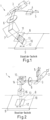
- In 1 is a schematic representation of a device 1 for generating or
- the device 1 comprises a scanner 2 with a rotatable mirror 3 and a Powell lens 4, which generates a line profile from a laser radiation 5 with a circular intensity profile.
- This line profile is transferred to a holographic recording material 8 via the rotatable mirror 3 and a lens 6 as well as a further mirror 7 and a hologram master 9 arranged underneath and designed as a master hologram.
- the exposure area 10, which is to be copied into the holographic recording material 8 by means of the laser radiation 5, is limited in its extent by means of a diaphragm 11, the diaphragm 11 being circular in the present example.
- FIG 2 1 shows a schematic representation of a further device 1 for generating an individualized hologram from the prior art.
- the same reference symbols in the figures denote the same features.
- the one in the 1 Device 1 shown comprises in FIG 2 Device 1 shown additionally has a polarizing beam splitter 14, on the upper side of which a spatial light modulator 15 is arranged in the form of an LCoS.
- the laser radiation 5, locally modulated by a rotation of a polarization of the laser radiation 5 and subsequent filtering by the beam splitter 14 on the basis of individualization information (e.g. a grayscale image of a person), is directed onto the holographic recording material 8 and the hologram master 9 with the aid of imaging optics 16.
- the areal exposure is carried out as in the in 1 example shown by scanning using the rotatable mirror 3 of the scanner 2.
- the individualized hologram in the holographic recording material 8 is thereby generated.
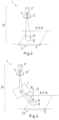
- FIG. 3 is a schematic, partial representation of an embodiment of the device 1 according to claim 1 according to the invention for generating a hologram with a hologram master, in particular shown in contact copy.
- the device 1 comprises an optical arrangement 20 , the optical arrangement 20 comprising a laser radiation source 21 , a diffractive optical element 22 and a master recording 23 .
- the master recording 23 is designed as a holding element or mount for receiving and holding the holographic recording material 8 and the hologram master 9 .
- the hologram master 9 is in particular a master hologram.
- the device 1 in the embodiment shown has no Powell lens, no scanner, no lens and no diaphragm.
- the diffractive optical element 22 is designed in such a way that, in a focal plane 24, a laser radiation 5 emitted by the laser radiation source 21 and transmitted through the diffractive optical element 22 is imaged onto an irradiation plane 17 in a beam path of the optical arrangement 20 and an exposure region 10 is thereby irradiated. which corresponds to a region 25 of the holographic recording material to be exposed in order to produce the hologram.
- the irradiation plane 17 corresponds to the plane in which the holographic recording material 8 is arranged.
- the exposure area 10 irradiated by the beam shaping of the diffractive optical element 22 therefore corresponds exactly to the area 25 in which the hologram is to be copied from the hologram master 9 into the holographic recording material 8 .
- this is a circular area.
- the intensity profile is homogeneous ("flat-top hat" profile).
- the optical arrangement 20 also includes a positionable and rotatable mirror 7, via which the laser radiation 5 transmitted through the diffractive optical element 20 is imaged onto the exposure region 10 at an angle 26 to the surface normal 27 of the holographic recording material 8 or the hologram master 9. This enables exposure or copying of the hologram at an angle 26 .
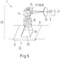
- FIG 5 shows a schematic, partial representation of another according to the invention Embodiment of the device 1, according to claim 1, for generating a hologram with a hologram master, in particular an individualized hologram.
- the same reference symbols in the figures denote the same features.
- the optical arrangement 20 includes in the beam path next to the Laser radiation source 21, the diffractive optical element 22 and the master recording 23 a polarizing beam splitter 14, on the top of which a spatial light modulator 15 is arranged in the form of an LCoS.
- the laser radiation 5 spatially modulated by the spatial light modulator 15 is directed onto the holographic recording material 8 and the hologram master 9 with the aid of imaging optics 16 of the optical arrangement 20 .
- the irradiation plane 17 coincides with an in-coupling plane 18 of the spatial light modulator 15, i.e. the diffractive optical element 22 is designed in such a way that the focal plane 24 of the diffractive optical element 22 is in the in-coupling plane 18.
- the laser radiation 5 transmitted through the diffractive optical element 22 is therefore imaged onto the spatial light modulator 15 or its in-coupling plane 18 .
- the laser radiation 5 spatially modulated by the SLM 15 or LCoS, in particular provided with individualization information, is then imaged with the aid of the imaging optics 16 onto an exposure area 10 which corresponds to an area 25 to be exposed.
- the exposure area 10 irradiated by the beam shaping of the diffractive optical element 22 thus corresponds exactly to the area 25 of the holographic recording material in which the hologram (individualized) is to be produced or copied. In the exemplary embodiment shown, this is a square area.
- the intensity profile of the laser radiation 5 in the focal plane 24 or in the exposure area 10 is homogeneous over the entire surface, so that uniform exposure or copying is possible.
- a diffractive optical element 22 (cf. e.g 3 ) selected and provided.
- the diffractive optical element 22 corresponds here with the laser radiation 5 used, in particular with regard to a wavelength of the laser radiation 5, and in particular with the hologram to be generated, in particular to be copied, or the hologram master 9. It can also be provided that the laser radiation 5 is widened in front of the diffractive optical element 22, thereby a beam profile through the diffractive Optical element 22 to make the transmitted laser radiation 5 more homogeneous.
- the diffractive optical element 22 is designed in such a way that during the subsequent exposure to light, precisely those areas are irradiated in which holograms are to be produced or copied.
- the selected and provided diffractive optical element 22 is arranged in a beam path of an optical arrangement 20 of the device 1 .
- a hologram master 9 and a holographic recording material 8 to be exposed are arranged in a master receptacle 23.
- the master holder 23 is designed, for example, as a flat table, on which the hologram master 9 and the holographic recording material 8 are placed and arranged one on top of the other in a predetermined position. Provision can also be made for the holographic recording material 8 to be or will be laminated onto the hologram master 9 . Furthermore, it can also be provided that the holographic recording material 8 is pressed and/or sucked onto the hologram master 23 so that both are arranged as closely as possible to one another and in particular there are no air pockets in between.
- laser radiation 5 is generated by means of a laser radiation source 21.
- the wavelength of the laser radiation 5 is matched to the holograms to be produced or to the hologram of the hologram master 9 to be reconstructed.
- the generated laser radiation is radiated onto the diffractive optical element 22 and holograms are thereby generated in exposure areas 10 or copied from the hologram master 9 into the holographic recording material 8.
Landscapes
- Physics & Mathematics (AREA)
- General Physics & Mathematics (AREA)
- Health & Medical Sciences (AREA)
- Electromagnetism (AREA)
- General Health & Medical Sciences (AREA)
- Toxicology (AREA)
- Engineering & Computer Science (AREA)
- Manufacturing & Machinery (AREA)
- Holo Graphy (AREA)
Description
- Die Erfindung betrifft eine Vorrichtung und ein Verfahren zum Erzeugen eines Hologramms mit einem Hologrammmaster, insbesondere in Kontaktkopie.
- Zur Absicherung von Wert- oder Sicherheitsdokumenten werden Hologramme als Sicherheitselemente eingesetzt. Die Hologramme erschweren eine Fälschung oder Nachahmung des Wert- oder Sicherheitsdokuments und erhöhen hierdurch dessen Sicherheit.
- Um Hologramme auch in der Massenproduktion von Wert- oder Sicherheitsdokumenten als Sicherheitsmerkmale einsetzen zu können, müssen Hologramme bei der Herstellung der Wert- oder Sicherheitsdokumente auf effiziente Weise hergestellt, insbesondere kopiert, werden.
- Ein Kopieren erfolgt üblicherweise im sogenannten Kontaktkopieverfahren. Hierzu wird ein zu kopierender Hologrammmaster in Form eines Masterhologramms hergestellt, in dem die holografische Information gespeichert ist. Anschließend wird ein zu belichtendes holografisches Aufzeichnungsmaterial, beispielsweise ein Hologrammfilm aus einem Fotopolymer, flächig an dem Hologrammmaster angeordnet. Wird der Hologrammmaster mit entsprechender Laserstrahlung bestrahlt, so wird das im Hologrammmaster gespeicherte Hologramm rekonstruiert und in den Hologrammfilm einbelichtet, d.h. in diesen hineinkopiert. Eine entsprechende Vorrichtung und ein entsprechendes Verfahren sind beispielsweise in der
EP 0 896 260 A2 beschrieben. - Insbesondere wird zum Erzeugen des Hologramms eine Laserstrahlung mittels einer Powell-Linse auf ein linienförmiges Profil gebracht. Die derart geformte Laserstrahlung wird anschließend mittels einer Linse auf das holografische Aufzeichnungsmaterial und den Hologrammmaster geführt. Die linienförmige Laserstrahlung wird mittels eines drehbaren Spiegels eines im Strahlengang angeordneten Scanners schrittweise über den Hologrammmaster und das holografische Aufzeichnungsmaterial geführt ("gescannt"). Um einen Bereich zu begrenzen, in dem eine Belichtung stattfindet, befindet sich im Strahlengang vor dem holografischen Aufzeichnungsmaterial und dem Hologrammmaster zusätzlich eine Blende. Auf diese Weise können beispielsweise kreisförmige oder quadratische Belichtungsbereiche geschaffen werden, die eine Belichtung begrenzen.
- Das beschriebene Verfahren ist jedoch aufwändig und langsam, da stets ein schrittweises Belichten des zu kopierenden Bereichs notwendig ist. Ferner ist das Verfahren aufgrund einer Vielzahl von optischen Komponenten kostspielig und fehleranfällig.
- Der Erfindung liegt die Aufgabe zu Grunde, eine Vorrichtung und ein Verfahren zum Erzeugen eines Hologramms zu schaffen, bei denen das Erzeugen verbessert durchgeführt werden kann.
- Aus der
US 2014/0055830 A1 sind eine Phasenmaske und eine Hologrammaufzeichnungsvorrichtung mit einer Phasenmaske zur Strahlformung bekannt. Die Phasenmaske enthält eine Phasenmodulationsschicht, die eine Phase verschiedener Teile des einfallenden Lichts unterschiedlich moduliert, so dass eine unterschiedliche optische Phasenverzögerung in einem Bereich zwischen 0 und 2 pi verschiedenen Teilen des einfallenden Lichts verliehen wird. Eine Hologrammaufzeichnungsvorrichtung umfasst eine Lichtquelle; ein optisches Signalstrahlsystem, das einen von der Lichtquelle emittierten Strahl in einen Referenzstrahl und einen Signalstrahl unterteilt, den Signalstrahl gemäß der Hologrammpixelinformation moduliert und den Signalstrahl auf ein Hologrammaufzeichnungsmedium strahlt. Das optische Signalstrahlsystem enthält die Phasenmaske. Die Hologrammaufzeichnungsvorrichtung enthält auch ein optisches Referenzstrahlsystem, das den Referenzstrahl auf das Hologrammaufzeichnungsmedium strahlt. - Aus der
DE 10 2015 220 123 A1 sind bekannt: ein Verfahren zum Herstellen eines Masterhologramms für ein Kontaktkopierverfahren, ein solches Masterhologramm sowie ein Verfahren zum Herstellen von individualisierten Hologrammen und individualisierte Hologramme, die mit einem solchen Masterhologramm im Kontaktkopierverfahren hergestellt sind. Das Verfahren zum Herstellen eines Masterhologramms umfasst die Schritte: Anordnen eines diffusen Streuers, einer Blende, einer Fourier-Linse und eines holografischen Aufzeichnungsmaterials auf einer optischen Anordnungsachse, sodass eine optischen Achse der Fourier-Linse, eine Oberflächennormale des holografischen Aufzeichnungsmaterials und eine Oberflächennormale einer Blendenöffnungsebene der Blende kollinear zur optischen Anordnungsachse sind, wobei die Blende zwischen dem diffusen Streuer und der Fourier-Linse unmittelbar an den diffusen Streuer angrenzend angeordnet wird und der diffuse Streuer in einer Brennebene der Fourier-Linse angeordnet wird und kohärentes erstes Licht auf den diffusen Streuer eingestrahlt wird, um hierdurch das diffus gestreute Licht zu erzeugen, welches mittels der Blende eingegrenzt und mittels der Fourier-Linse in das holografische Aufzeichnungsmaterial als Objekt-Licht geleitet wird und zu dem ersten kohärenten Licht kohärentes zweites kohärentes Licht von einer der Fourier-Linse abgewandten Seite in das holografische Aufzeichnungsmaterial als Referenzlicht eingestrahlt wird, um in dem holografischen Aufzeichnungsmaterial ein Reflexionsvolumenhologramm auszubilden. Das Dokument offenbart darüberhinaus die Verwendung eines Strahlenformungselements zur Ausleuchtung eines räumlichen Lichtmodulators. - Aus der
DE 10 2012 215 540 A1 ist eine Individualisierungseinrichtung bekannt, die ausgebildet ist, Licht einer Lichtquelle aus einer Empfangsrichtung zu empfangen und räumlich moduliertes Licht unter einer Ausgaberichtung für eine Holgrammbelichtung auszugeben, umfassend einen räumlichen Lichtmodulator, und eine Strahlführungsoptik, um das Licht der Lichtquelle auf den räumlichen Lichtmodulator zu führen und das von dem räumlichen Lichtmodulator modulierte Licht wegzuführen, wobei eine Oberflächennormale des räumlichen Lichtmodulators zumindest gegenüber einer Oberflächennormale einer ersten Grenzfläche einer Komponente der Strahlführungsoptik verkippt ist, die das modulierte Licht nach der Modulation an dem räumlichen Lichtmodulator passiert. Ferner ist eine Belichtungseinrichtung für Hologramme bekannt, die eine solche Individualisierungseinrichtung umfasst. - Aus Xin Tan et al., Diffractive phase elements for beam shaping: a new design method, Applied Optics, Optical Society of America, Washington D.C., USA, Bd. 34, Nr. 8, 10. März 1995, S. 1314-1320, ISSN: 0003-6935, sind Diffraktive Phasenelemente zur Strahlformung bekannt.
- Aus
WO2011070350 ist bekannt mehrere holographische Pixel mit Hilfe eines holographischen optischen Elements, zur Zeitersparnis, gleichzeitig zu beleuchten. - Die Aufgabe wird erfindungsgemäß durch eine Vorrichtung mit den Merkmalen des Patentanspruchs 1 und ein Verfahren mit den Merkmalen des Patentanspruchs 8 gelöst. Vorteilhafte Ausgestaltungen der Erfindung ergeben sich aus den Unteransprüchen.
- Als Wert- oder Sicherheitsdokument werden jene Gegenstände bezeichnet, die mindestens ein Sicherheitsmerkmal aufweisen. Beispielhaft sind als Sicherheitsdokumente genannt: Personalausweise, Reisepässe, ID-Karten, Zugangskontrollausweise, Visa, Steuerzeichen, Tickets, Führerscheine, Kraftfahrzeugpapiere, Wertdokumente, wie Banknoten, Schecks, Postwertzeichen, Kreditkarten, beliebige Chipkarten und Haftetiketten (z.B. zur Produktsicherung).
- Als Diffraktives Optisches Element wird ein optisches Element bezeichnet, das ein optisches Gitter umfasst, und das unter Ausnutzung von Beugungseffekten an diesem optischen Gitter eine Strahlformung vornimmt. Insbesondere handelt es sich bei einem Diffraktiven Optischen Element um Glasträger, auf dessen Oberflächen Mikrostrukturen aufgebracht sind, welche das optische Gitter ausbilden. Durch die Mikrostrukturen weisen einzelne Teilstrahlen unterschiedliche Weglängen auf, sodass es zu Phasenmodulationen kommt, die zu Interferenzmustern führen können. Durch konstruktive und destruktive Überlagerung wird zusätzlich eine Amplitude moduliert. Durch gezieltes Ausbilden der Mikrostrukturen kann eine durch das Diffraktive Optische Element transmittierte Laserstrahlung in seiner Form und in seiner Intensität verändert und eingestellt werden, insbesondere mit Bezug auf eine Fokusebene. Die optisch wirksamen Mikrostrukturen können mittels einer Modulation des Brechungsindex und/oder mittels einer Modulation eines Höhenprofils der Oberfläche erzeugt werden.
- Als holografisches Aufzeichnungsmaterial wird jedes Material bezeichnet, welches geeignet ist, um darin ein Volumenhologramm einzubelichten. Insbesondere kann ein holografisches Aufzeichnungsmaterial ein Hologrammfilm sein. Insbesondere eignen sich auf Fotopolymerbasis hergestellte Hologrammfilme. Es können jedoch auch Hologrammfilme verwendet werden, die auf Silberhalogenidbasis hergestellt sind, insbesondere gebleichte Silberhalogenidfilme. Andere Materialien sind Dichromatgelantine oder photorefraktive Kristalle. Es wird im Folgenden jeweils davon ausgegangen, dass das holografische Aufzeichnungsmaterial bzw. ein Hologrammmaster oder Masterhologramm jeweils glatt flächig und eben ausgebildet sind. Kleinere Abweichungen zur Beseitigung von Abbildungsfehlern oder Ähnlichem sind hiervon nicht berührt.
- Ein Hologrammmaster ist ein Muster, von dem ein Hologramm hergestellt wird. Ein solcher Hologrammmaster kann beispielsweise ein Masterhologramm, ein Spiegel oder ein Gitter sein. Ein Masterhologramm ist ein als Hologramm ausgebildeter Hologrammmaster. Beispielsweise dient eine Mattscheibe im Stand der Technik als Hologrammmaster. Das davon in Kontaktkopie hergestellte Volumenreflexionshologramm stellt ein Masterhologramm dar, welches im Kontaktkopierverfahren zur Herstellung individualisierter Sicherheitselemente als Hologrammmaster eingesetzt werden kann. Dieses Masterhologramm ist dann in dem Kontaktkopierverfahren auch der Hologrammmaster für die individualisiert hergestellten Sicherheitselemente, die jeweils ein individualisiertes Volumenhologramm besitzen, welches von dem Masterhologramm im Kontaktkopierverfahren räumlich selektiert kopiert ist.
- Ein Spatial Light Modulator (SLM) erlaubt eine zweidimensional ortsaufgelöste Beleuchtung bzw. Bestrahlung eines meist flächigen Gegenstandes mit modulierter Intensität. Hierbei kann es sich beispielsweise um einen DMD (Digital Micro Mirror Device) Chip, ein LCD (Liquid Crystal Display) Transmissionsdisplay oder ein LCoS (Liquid Crystal on Silicon) Display handeln. Allen ist gemeinsam, dass eine Vielzahl von SLM-Pixeln gebildet ist, wobei jedes SLM-Pixel unabhängig von anderen SLM-Pixeln aktivierbar oder deaktivierbar ist (auch Zwischenstufen sind möglich), wodurch durch entsprechende Ansteuerung der SLM-Pixel sich Muster oder Bilder projizieren lassen. Durch die freie Ansteuerbarkeit können auch ohne weiteres verschiedene Bilder oder Muster in zeitlicher Folge hintereinander generiert werden, beispielsweise in Form eines Passfotos.
- Ein Code bzw. Muster ist individualisierend, wenn er einzigartig für eine Person oder einen Gegenstand oder eine Gruppe von Personen oder Gegenständen aus einer größeren Gesamtmenge an Personen oder Gegenständen ist. Ein für eine Gruppe von Personen innerhalb der Gesamtmenge der Einwohner eines Landes individualisierender Code ist beispielsweise die Stadt des Wohnortes. Ein für eine Person individualisierender Code ist beispielsweise die Nummer des Personalausweises oder das Passbild. Ein für eine Gruppe von Geldscheinen innerhalb der Gesamtmenge der Geldscheine individualisierender Code ist die Wertigkeit. Für einen Geldschein individualisierend ist die Seriennummer. Beispiele für nicht individualisierende Codes bzw. Muster sind Wappen, Siegel, Hoheitszeichen, etc.
- Eine Grundidee der Erfindung ist, einen optischen Aufbau einer Vorrichtung zum Erzeugen des Hologramms zu vereinfachen. Hierzu wird insbesondere auf die Powell-Linse, den Scanner, weitere Linsen und die Blende im Strahlengang verzichtet. Hingegen wird ein Diffraktives Optisches Element eingesetzt. Das Diffraktive Optische Element wird hierbei derart ausgebildet bzw. ausgewählt, dass ein Belichtungsbereich mit dem zum Erzeugen des Hologramms zu belichtenden Bereich korrespondiert. Korrespondieren bedeutet hierbei, dass der Bereich, der belichtet wird, hinsichtlich einer Form und einer Größe bzw. Fläche mit dem zu erzeugenden, zu kopierenden, Teil übereinstimmt. Es kann hierbei jedoch auch vorgesehen sein, dass nicht der gesamte Hologrammmaster ausgeleuchtet wird, sondern nur der Teil bzw. Bereich, mittels dessen ein Hologramm erzeugt bzw. kopiert werden soll. Soll beispielsweise ein kreisförmiger Bereich kopiert werden, so wird das Diffraktive Optische Element derart ausgebildet, dass die in der Fokusebene des Diffraktiven Optischen Elements abgestrahlte Laserstrahlung diesem kreisförmigen Bereich entspricht. Soll hingegen ein quadratischer Belichtungsbereich belichtet werden, beispielsweise, weil das zu erzeugende oder zu kopierende Hologramm eine quadratische Form aufweist, so wird das Diffraktive Optische Element derart ausgebildet bzw. ausgewählt, dass die in den Belichtungsbereich abgestrahlte bzw. transmittierte Laserstrahlung diesem quadratischen Bereich entspricht. Auf diese Weise kann das zu erzeugende, insbesondere zu kopierende, Hologramm über die gesamte Fläche in einem einzigen Belichtungsschritt erzeugt bzw. kopiert werden. Insbesondere wird eine Vorrichtung zum Erzeugen eines Hologramms entsprechend Anspruch 1 geschaffen.
- Ferner wird ein Verfahren zum Erzeugen eines Hologramms entsprechend Anspruch 8 zur Verfügung gestellt.
- Der Vorteil der Vorrichtung und des Verfahrens ist, dass auf eine Powell-Linse, einen Scanner, eine Linse und eine Blende zur Strahlformung verzichtet werden kann. Dies ermöglicht einen deutlich vereinfachten Aufbau der Vorrichtung bzw. ein vereinfachtes Verfahren, da insbesondere eine Justierung der optischen Anordnung weniger aufwändig ausgestaltet werden kann. Insgesamt können Kosten und Aufwand eingespart werden. Darüber hinaus reduziert sich aufgrund der geringeren Anzahl an Bauteilen der optischen Anordnung auch eine Fehleranfälligkeit, sodass die Vorrichtung und das Verfahren robuster sind.
- Das Diffraktive Optische Element ist derart ausgebildet, in der Fokusebene die von der Laserstrahlungsquelle ausgesandte und durch das Diffraktive Optische Element transmittierte Laserstrahlung auf mindestens eine weitere Einstrahlebene in dem Strahlengang der optischen Anordnung abzubilden und hierdurch mindestens einen weiteren Belichtungsbereich zu bestrahlen, der mit einem zum Erzeugen eines weiteren Hologramms zu belichtenden weiteren Bereich des holografischen Aufzeichnungsmaterials korrespondiert. Hierdurch wird es möglich, mehrere Belichtungsbereiche getrennt voneinander, jedoch gleichzeitig zu belichten und auf diese Weise beispielsweise mehrere Hologramme gleichzeitig für unterschiedliche Wert- oder Sicherheitsdokumente zu erzeugen bzw. zu kopieren. Hierdurch können beispielsweise mehrere Wert- oder Sicherheitsdokumente auf einem Mehrfachnutzen in einem einzigen Arbeitsschritt jeweils mit einem Hologramm versehen werden, da alle Hologramme gleichzeitig erzeugt bzw. kopiert werden können. Hierdurch kann ein Ablauf vereinfacht werden.
- Es kann auch vorgesehen sein, dass mehrere verschiedene Hologramme für ein einzelnes Wert- oder Sicherheitsdokument gleichzeitig erzeugt bzw. kopiert werden.
- Das Diffraktive Optische Element ist dann entsprechend zum Belichten von mehreren korrespondierenden Belichtungsbereichen ausgelegt.
- Die konkrete Ausbildung der Mikrostrukturen des Diffraktiven Optischen Elements wird in Abhängigkeit der angestrebten Lage der Fokusebene des Diffraktiven Optischen Elements und in Abhängigkeit des zu belichtenden Bereichs bzw. des Belichtungsbereichs vorgenommen. Hierzu wird eine Rückwärtsrechnung ausgehend von der Form und der Größe des zu belichtenden Bereichs vorgenommen, um die beugenden Mikrostrukturen auszubilden. Anders ausgedrückt wird durch Simulation eine konkrete Position und eine konkrete Form der Mikrostrukturen auf der Oberfläche des Glasträgers des Diffraktiven Optischen Elements derart aufgefunden, dass sich in der Fokusebene das gewünschte Bild der durch das Diffraktive Optische Element transmittierten Laserstrahlung für die Einstrahlebene, und hierdurch insbesondere für den Belichtungsbereich, ergibt. Das Diffraktive Optische Element wird dann durch Ausbilden der berechneten Mikrostrukturen auf der Oberfläche eines Glasträgers hergestellt. Hierzu werden die berechneten Mikrostrukturen durch mehrere sukzessiv aufeinanderfolgende Ätzschritte ausgebildet. Ein Hersteller von Diffraktiven Optischen Elementen ist beispielsweise die Firma HOLO/OR Ltd. in Israel (http://www.holoor.co.il/).
- Im einfachsten Fall wird die von dem Diffraktiven Optischen Element transmittierte Laserstrahlung direkt auf den Belichtungsbereich geführt. Dann fällt die Einstrahlebene mit der Ebene, in der das Hologramm erzeugt werden soll, zusammen. Sind zwischen dem Diffraktiven Optischen Element optische Bauteile angeordnet, muss die Einstrahlebene gegebenenfalls mit einer anderen Ebene zusammenfallen und das Diffraktive Optische Element entsprechend ausgebildet sein oder ausgewählt werden. Die Masteraufnahme ist beispielsweise als Halteelement, Fassung oder Tisch zum Aufnehmen und/oder Halten des holografischen Aufzeichnungsmaterials und des Hologrammmasters ausgebildet.
- Es kann insbesondere vorgesehen sein, dass das erzeugte bzw. kopierte Hologramm als Sicherheitsmerkmal in einem Wert- oder Sicherheitsdokument eingesetzt wird.
- Je nach Form des zu erzeugenden oder zu kopierenden Hologramms kann der zu belichtende Bereich in Bezug auf Form, Größe und/oder Belichtungsintensität variieren. In einer Ausführungsform ist deshalb vorgesehen, dass das Diffraktive Optische Element derart ausgebildet ist, dass eine Strahlform und/oder ein Intensitätsprofil der transmittierten Laserstrahlung auf den zu belichtenden Bereich abgestimmt ist.
- Es kann vorgesehen sein, dass ein Hologramm unter einem bestimmten Winkel rekonstruiert bzw. in dem holographischen Auszeichnungsmaterial erzeugt werden soll. In einer Ausführungsform ist deshalb vorgesehen, dass die optische Anordnung einen Spiegel umfasst, wobei der Spiegel derart ausgebildet und angeordnet ist, dass die Laserstrahlung in Bezug auf eine Flächennormale des zu belichtenden holografischen Aufzeichnungsmaterials unter einem Winkel auf dieses abgebildet werden kann. Beträgt ein solcher Winkel beispielsweise 45°, so wird der Spiegel entsprechend in den Strahlengang auf der optischen Achse zwischen das Diffraktive Optische Element und der Masteraufnahme angeordnet. Die Ausrichtung erfolgt dann derart, dass die an dem Spiegel reflektierte transmittierte Laserstrahlung unter einem Winkel von 45° auf das holografische Auszeichnungsmaterial und den Hologrammmaster trifft.
- Es kann hierbei insbesondere vorgesehen sein, dass das Diffraktive Optische Element derart ausgebildet ist bzw. hergestellt oder ausgewählt wurde, dass eine aufgrund der Belichtung unter einem Winkel auftretende Verzerrung bzw. Stauchung/Streckung des Strahlprofils berücksichtigt wird. Wäre eine Strahlform bzw. ein Intensitätsprofil nach der Transmission durch das Diffraktive Optische Element beispielsweise kreisförmig, so wäre der belichtete Bereich nach einer Spiegelung an einem Spiegel unter einem Winkel von 45° in Bezug auf die Flächennormale des holografischen Aufzeichnungsmaterials bzw. des Hologrammmasters ellipsenförmig. Dies kann jedoch durch entsprechende Berücksichtigung beim Ausbilden des Diffraktiven Optischen Elements berücksichtigt werden, sodass trotz der Spiegelung eine Belichtung mit kreisförmiger Strahlform bzw. kreisförmigem Intensitätsprofil stattfinden kann.
- Es kann gewünscht sein, Hologramme unter verschiedenen Winkeln in ein holographisches Aufzeichnungsmaterial zu kopieren. In einer Ausführungsform ist daher vorgesehen, dass der Spiegel in seiner Position verstellbar ausgebildet ist und/oder mindestens eine Achse des Spiegels drehbar ausgebildet ist, sodass der Winkel veränderbar ist. Hierdurch kann die Vorrichtung flexibel an wechselnde Anforderungen, d.h. wechselnde Winkel, angepasst werden, sodass Umrüst- und Standzeiten der Vorrichtung verringert werden können.
- Im Verfahren kann ein entsprechend vorgesehen sein, dass der Spiegel positioniert und der Winkel eingestellt wird.
- Es kann gewünscht sein, Hologramme zu individualisieren, beispielsweise indem die Hologramme mit einer individualisierten Nummer oder einem individuellen Bild versehen werden. In einer Ausführungsform ist deshalb vorgesehen, dass die optische Anordnung einen im Strahlengang angeordneten Spatial Light Modulator (SLM) umfasst, wobei der Spatial Light Modulator derart ausgebildet ist, das zu erzeugende Hologramm zu individualisieren, wobei die Einstrahlebenen mit einer Einkopplungsebene des Spatial Light Modulators zusammenfallen.
- Der SLM wird dann hinter das Diffraktive Optische Element angeordnet. Die durch den SLM modulierte Laserstrahlung wird dann beispielsweise über eine Abbildungsoptik auf den Belichtungsbereich abgebildet und durch entsprechende Ansteuerung des SLM individualisiert.
- Insbesondere ist in einer Ausführungsform vorgesehen, dass der Spatial Light Modulator ein Liquid-Crystal-on-Silicon-Modulator ist.
- In einer Ausführungsform ist vorgesehen, dass das Diffraktive Optische Element derart ausgebildet ist, einen Transmissionsgrad von mindestens 99 % und einen Wirkungsgrad von mindestens 97 % aufzuweisen. Dies erfolgt, indem beim Herstellen des Diffraktiven Optischen Elements mindestens 32 Ätzstufen verwendet werden, das heißt dass mindestens 5 Ätzschritte durchgeführt werden. Hierdurch lässt sich ein Wirkungsgrad gegenüber der aus dem Stand der Technik bekannten Vorrichtungen deutlich steigern. Das Kopieren von Hologrammen kann hierdurch effizienter und kostengünstiger durchgeführt werden.
- Die Vorteile des Verfahrens sind dieselben wie die der Vorrichtung.
- Nachfolgend wird die Erfindung anhand bevorzugter Ausführungsbeispiele unter Bezugnahme auf die Figuren näher erläutert. Hierbei zeigen:
- Fig. 1
- eine schematische Darstellung einer Vorrichtung zum Erzeugen eines Hologramms aus dem Stand der Technik;
- Fig. 2
- eine schematische Darstellung einer weiteren Vorrichtung zum Erzeugen eines individualisierten Hologramms aus dem Stand der Technik;
- Fig. 3
- eine schematische, teilweise Darstellung einer Ausführungsform der Vorrichtung zum Erzeugen eines Hologramms;
- Fig. 4
- eine schematische, teilweise Darstellung einer weiteren Ausführungsform der Vorrichtung zum Erzeugen eines Hologramms;
- Fig. 5
- eine schematische, teilweise Darstellung einer weiteren Ausführungsform der Vorrichtung zum Erzeugen eines individualisierten Hologramms;
- Fig. 6
- ein schematisches Ablaufdiagramm einer Ausführungsform des Verfahrens zum Erzeugen eines Hologramms.
- In
Fig. 1 ist eine schematische Darstellung einer Vorrichtung 1 zum Erzeugen bzw. - Kopieren eines Hologramms in Kontaktkopie aus dem Stand der Technik gezeigt. Die Vorrichtung 1 umfasst einen Scanner 2 mit einem drehbaren Spiegel 3 und eine Powell-Linse 4, welche aus einer Laserstrahlung 5 mit kreisrundem Intensitätsprofil ein Linienprofil erzeugt. Dieses Linienprofil wird über den drehbaren Spiegel 3 und eine Linse 6 sowie einen weiteren Spiegel 7 auf ein holografisches Aufzeichnungsmaterial 8 und einen darunter angeordneten und als Masterhologramm ausgebildeten Hologrammmaster 9 abgebildet. Hierbei wird der Belichtungsbereich 10, der mittels der Laserstrahlung 5 in das holografische Aufzeichnungsmaterial 8 kopiert werden soll, mittels einer Blende 11 in seiner Ausdehnung begrenzt, wobei die Blende 11 im vorliegenden Beispiel kreisförmig ausgebildet ist. Ein flächiges Kopieren bzw. ein flächiges Belichten des Belichtungsbereichs 10 erfolgt nun sequentiell durch Scannen mittels des drehbaren Spiegels 3 des Scanners 2, sodass die linienförmige Abbildung 13 der Laserstrahlung 5 entlang einer Scanrichtung 12 über das holografische Aufzeichnungsmaterial 8 und den Hologrammmaster 9 hinwegbewegt wird. Hierdurch wird das Hologramm für den Belichtungsbereich 10 im Hologrammmaster 9 rekonstruiert und in das holografische Aufzeichnungsmaterial 8 hineinbelichtet.
- In
Fig. 2 ist eine schematische Darstellung einer weiteren Vorrichtung 1 zum Erzeugen eines individualisierten Hologramms aus dem Stand der Technik gezeigt. Gleiche Bezugszeichen in den Figuren bezeichnen hierbei gleiche Merkmale. Im Gegensatz zu der in derFig. 1 gezeigten Vorrichtung 1 umfasst die in derFig. 2 gezeigte Vorrichtung 1 zusätzlich einen polarisierenden Strahlteiler 14, an dessen Oberseite ein Spatial Light Modulator 15 in Form eines LCoS angeordnet ist. Die örtlich durch eine Drehung einer Polarisation der Laserstrahlung 5 und anschließende Filterung durch den Strahlteiler 14 auf Grundlage einer Individualisierungsinformation (z.B. ein Graustufenbild einer Person) modulierte Laserstrahlung 5 wird mit Hilfe einer Abbildungsoptik 16 auf das holographische Aufzeichnungsmaterial 8 und den Hologrammmaster 9 geleitet. Das flächige Belichten erfolgt wie bei dem inFig. 1 gezeigten Beispiel durch Scannen mittels des drehbaren Spiegels 3 des Scanners 2. Hierdurch wird das individualisierte Hologramm in dem holographischen Aufzeichnungsmaterial 8 erzeugt. - In
Fig. 3 ist eine schematische, teilweise Darstellung einer Ausführungsform der erfindungsgemäßen Vorrichtung 1, entsprechend Anspruch 1, zum Erzeugen eines Hologramms mit einem Hologrammmaster, insbesondere in Kontaktkopie gezeigt. Die Vorrichtung 1 umfasst eine optische Anordnung 20, wobei die optische Anordnung 20 eine Laserstrahlungsquelle 21, ein Diffraktives Optisches Element 22 und eine Masteraufnahme 23 umfasst. Die Masteraufnahme 23 ist als Halteelement oder Fassung zum Aufnehmen und Halten des holografischen Aufzeichnungsmaterials 8 und des Hologrammmasters 9 ausgebildet. - Der Hologrammmaster 9 ist in der gezeigten Ausführungsform insbesondere ein Masterhologramm.
- Im Gegensatz zu den Vorrichtungen 1 im Stand der Technik weist die Vorrichtung 1 in der gezeigten Ausführungsform keine Powell-Linse, keinen Scanner, keine Linse und keine Blende auf.
- Das Diffraktive Optische Element 22 ist derart ausgebildet, dass in einer Fokusebene 24 eine von der Laserstrahlungsquelle 21 ausgesandte und durch das Diffraktive Optische Element 22 transmittierte Laserstrahlung 5 auf eine Einstrahlebene 17 in einem Strahlengang der optischen Anordnung 20 abgebildet und hierdurch ein Belichtungsbereich 10 bestrahlt wird, der mit einem zum Erzeugen des Hologramms zu belichtenden Bereich 25 des holografischen Aufzeichnungsmaterials korrespondiert. Die Einstrahlebene 17 entspricht in dieser Ausführungsform der Ebene, in der das holographische Aufzeichnungsmaterial 8 angeordnet ist. Der durch die Strahlformung des Diffraktiven Optischen Elements 22 bestrahlte Belichtungsbereich 10 entspricht daher genau dem Bereich 25, in dem das Hologramm von dem Hologrammmaster 9 in das holografische Aufzeichnungsmaterial 8 kopiert werden soll. Im gezeigten Ausführungsbeispiel ist dies eine kreisförmige Fläche. Vorzugsweise ist das Intensitätsprofil homogen ausgebildet ("Flat-top hat"-Profil).
- In
Fig. 4 ist eine schematische, teilweise Darstellung einer weiteren erfindungsgemäßen Ausführungsform der Vorrichtung 1, entsprechend Anspruch 1, zum Erzeugen eines Hologramms mit einem Hologrammmaster, insbesondere in Kontaktkopie gezeigt. Die Vorrichtung 1 basiert auf der inFig. 3 gezeigten Ausführungsform. Gleiche Bezugszeichen in den Figuren bezeichnen hierbei gleiche Merkmale. Zusätzlich umfasst die optische Anordnung 20 noch einen positionierbaren und drehbaren Spiegel 7, über den die durch das Diffraktive Optische Element 20 transmittierte Laserstrahlung 5 unter einem Winkel 26 zur Flächennormalen 27 des holografischen Aufzeichnungsmaterials 8 bzw. des Hologrammmasters 9 auf den Belichtungsbereich 10 abgebildet wird. Hierdurch wird ein Belichten bzw. ein Kopieren des Hologramms unter einem Winkel 26 ermöglicht. -
Fig. 5 zeigt eine schematische, teilweise Darstellung einer weiteren erfindungsgemäßen Ausführungsform der Vorrichtung 1, entsprechend Anspruch 1, zum Erzeugen eines Hologramms mit einem Hologrammmaster, insbesondere eines individualisierten Hologramms. Gleiche Bezugszeichen in den Figuren bezeichnen hierbei gleiche Merkmale. Die optische Anordnung 20 umfasst im Strahlengang neben der Laserstrahlungsquelle 21, dem Diffraktiven Optischen Element 22 und der Masteraufnahme 23 einen polarisierenden Strahlteiler 14, an dessen Oberseite ein Spatial Light Modulator 15 in Form eines LCoS angeordnet ist. Die durch den Spatial Light Modulator 15 örtlich modulierte Laserstrahlung 5 wird mit Hilfe einer Abbildungsoptik 16 der optischen Anordnung 20 auf das holographische Aufzeichnungsmaterial 8 und den Hologrammmaster 9 geleitet. - Die Einstrahlebene 17 fällt in dieser Ausführungsform mit einer Einkopplungsebene 18 des Spatial Light Modulators 15 zusammen, d.h. das Diffraktive Optische Element 22 ist derart ausgebildet, dass sich die Fokusebene 24 des Diffraktiven Optischen Elements 22 in der Einkopplungsebene 18 befindet. Die durch das Diffraktive Optische Element 22 transmittierte Laserstrahlung 5 wird daher auf den Spatial Light Modulator 15 bzw. dessen Einkopplungsebene 18 abgebildet.
- Die von dem SLM 15 bzw. LCoS örtlich modulierte, insbesondere mit einer Individualisierungsinformation versehene Laserstrahlung 5 wird anschließend mit Hilfe der Abbildungsoptik 16 auf einen Belichtungsbereich 10 abgebildet, der mit einem zu belichtenden Bereich 25 korrespondiert. Der durch die Strahlformung des Diffraktiven Optischen Elements 22 bestrahlte Belichtungsbereich 10 entspricht somit genau dem Bereich 25 des holografischen Aufzeichnungsmaterials, in dem das Hologramm (individualisiert) erzeugt bzw. kopiert werden soll. Im gezeigten Ausführungsbeispiel ist dies eine quadratische Fläche. Vorzugsweise ist das Intensitätsprofil der Laserstrahlung 5 in der Fokusebene 24 bzw. in dem Belichtungsbereich 10 hierbei homogen über die gesamte Fläche ausgebildet, sodass ein gleichmäßiges Belichten bzw. Kopieren möglich ist.
- In
Fig. 6 ist ein schematisches Ablaufdiagramm des erfindungsgemäßen Verfahrens zum Erzeugen eines Hologramms dargestellt. - In einem ersten Verfahrensschritt 100 wird ein Diffraktives Optisches Element 22 (vgl. z.B.
Fig. 3 ) ausgewählt und bereitgestellt. Das Diffraktive Optische Element 22 korrespondiert hierbei mit der verwendeten Laserstrahlung 5, insbesondere in Bezug auf eine Wellenlänge der Laserstrahlung 5, und insbesondere mit dem zu erzeugenden, insbesondere zu kopierenden, Hologramm bzw. dem Hologrammmaster 9. Es kann zusätzlich vorgesehen sein, dass die Laserstrahlung 5 vor dem Diffraktiven Optischen Element 22 aufgeweitet wird, um hierdurch ein Strahlprofil der durch das Diffraktive Optische Element 22 transmittierten Laserstrahlung 5 homogener zu gestalten. Das Diffraktive Optische Element 22 ist derart ausgebildet, dass beim nachfolgenden Belichten genau die Bereiche bestrahlt werden, in denen Hologramme erzeugt bzw. kopiert werden sollen. - Das ausgewählte und bereitgestellte Diffraktive Optische Element 22 wird in einen Strahlengang einer optischen Anordnung 20 der Vorrichtung 1 angeordnet.
- In einem Verfahrensschritt 101 wird ein Hologrammmaster 9 und ein zu belichtendes holografisches Aufzeichnungsmaterial 8 in einer Masteraufnahme 23 angeordnet. Die Masteraufnahme 23 ist beispielsweise als ebener Tisch ausgebildet, auf der der Hologrammmaster 9 und das holografische Aufzeichnungsmaterial 8 aufgelegt werden und in einer vorgegebenen Position aufeinander angeordnet werden. Es kann auch vorgesehen sein, dass das holografische Aufzeichnungsmaterial 8 auf den Hologrammmaster 9 auflaminiert ist oder wird. Ferner kann auch vorgesehen sein, dass das holografische Aufzeichnungsmaterial 8 an den Hologrammmaster 23 angedrückt und/oder angesaugt wird, damit beide möglichst eng aneinander angeordnet sind und sich insbesondere keine Lufteinschlüsse dazwischen befinden.
- Im nächsten Verfahrensschritt 102 wird Laserstrahlung 5 mittels einer Laserstrahlungsquelle 21 erzeugt. Hierbei ist die Wellenlänge der Laserstrahlung 5 auf die zu erzeugenden Hologramme bzw. das zu rekonstruierende Hologramm des Hologrammmasters 9 abgestimmt.
- Im Verfahrensschritt 103 wird die erzeugte Laserstrahlung auf das Diffraktive Optische Element 22 eingestrahlt und hierdurch in Belichtungsbereichen 10 Hologramme erzeugt bzw. aus dem Hologrammmaster 9 in das holografische Aufzeichnungsmaterial 8 kopiert.
-
- 1
- Vorrichtung
- 2
- Scanner
- 3
- Spiegel
- 4
- Powell-Linse
- 5
- Laserstrahlung
- 6
- Linse
- 7
- Spiegel
- 8
- holografisches Aufzeichnungsmaterial
- 9
- Hologrammmaster
- 10
- Belichtungsbereich
- 11
- Blende
- 12
- Scanrichtung
- 13
- linienförmige Abbildung
- 14
- polarisierender Strahlteiler
- 15
- Spatial Light Modulator
- 16
- Abbildungsoptik
- 17
- Einstrahlebene
- 18
- Einkopplungsebene
- 20
- optische Anordnung
- 21
- Laserstrahlungsquelle
- 22
- Diffraktives Optisches Element
- 23
- Masteraufnahme
- 24
- Fokusebene
- 25
- Bereich
- 26
- Winkel
- 27
- Flächennormale
- 100-103
- Verfahrensschritte
Claims (10)
- Vorrichtung (1) zum Erzeugen eines Hologramms mit einem Hologrammmaster (9), umfassend:eine optische Anordnung (20),wobei die optische Anordnung (20) entlang einer optischen Achse mindestens eine Laserstrahlungsquelle (21), ein Diffraktives Optisches Element (22) und eine Masteraufnahme (23) aufweist, wobei die Masteraufnahme (23) dazu eingerichtet ist, dass in oder auf dieser ein zu belichtendes holografisches Aufzeichnungsmaterial (8) und der Hologrammmaster (9) angeordnet werden können,undwobei das Diffraktive Optische Element (22) derart ausgebildet ist, eine von der Laserstrahlungsquelle (21) ausgesandte und durch das Diffraktive Optische Element (22) transmittierte Laserstrahlung (5) in Bezug auf eine Fokusebene (24) des Diffraktiven Optischen Elements (22) in seiner Form und seiner Intensität zu verändern und einzustellen und auf eine Einstrahlebene (17) in einem Strahlengang der optischen Anordnung (20) abzubilden und hierdurch einen ersten Belichtungsbereich (10) zu bestrahlen, der mit einem zum Erzeugen des Hologramms zu belichtenden Bereich (25) des holografischen Aufzeichnungsmaterials (8) korrespondiert,wobei das Diffraktive Optische Element (22) ferner derart ausgebildet ist, die von der Laserstrahlungsquelle (21) ausgesandte und durch das Diffraktive Optische Element (22) transmittierte Laserstrahlung (5) in Bezug auf die Fokusebene (24) in seiner Form und seiner Intensität zu verändern und einzustellen und auf mindestens eine weitere Einstrahlebene (17) in dem Strahlengang der optischen Anordnung (20) abzubilden und hierdurch mindestens einen weiteren Belichtungsbereich, räumlich getrennt vom ersten Belichtungsbereich auf dem holografischen Aufzeichnungsmaterial (8), zu bestrahlen, der mit einem zum Erzeugen eines weiteren Hologramms zu belichtenden weiteren Bereich des holografischen Aufzeichnungsmaterials (8) korrespondiert.
- Vorrichtung (1) nach Anspruch 1, dadurch gekennzeichnet, dass das Diffraktive Optische Element (22) derart ausgebildet ist, dass ein Intensitätsprofil der transmittierten Laserstrahlung (5) auf die zu belichtenden Bereiche (25) abgestimmt ist.
- Vorrichtung (1) nach Anspruch 1 oder 2, dadurch gekennzeichnet, dass die optische Anordnung (20) einen Spiegel (7) umfasst, wobei der Spiegel (7) derart ausgebildet und angeordnet ist, dass die Laserstrahlung (5) in Bezug auf eine Flächennormale (27) des zu belichtenden holografischen Aufzeichnungsmaterials (8) unter einem Winkel (26) auf dieses abgebildet werden kann.
- Vorrichtung (1) nach Anspruch 3, dadurch gekennzeichnet, dass der Spiegel (7) in seiner Position verstellbar ausgebildet ist und/oder mindestens eine Achse des Spiegels (7) drehbar ausgebildet ist, sodass der Winkel (7) veränderbar ist.
- Vorrichtung (1) nach einem der vorangegangenen Ansprüche, dadurch gekennzeichnet, dass die optische Anordnung (20) einen im Strahlengang angeordneten Spatial Light Modulator (15) umfasst, wobei der Spatial Light Modulator (15) derart ausgebildet ist, das zu erzeugende Hologramm zu individualisieren, wobei die Einstrahlebenen (17) mit einer Einkopplungsebene (18) des Spatial Light Modulators (15) zusammenfallen.
- Vorrichtung (1) nach Anspruch 5, dadurch gekennzeichnet, dass der Spatial Light Modulator (15) ein Liquid-Crystal-on-Silicon-Modulator ist.
- Vorrichtung (1) nach einem der vorangegangenen Ansprüche, dadurch gekennzeichnet, dass das Diffraktive Optische Element (22) mindestens 32 Ätzstufen aufweist, sodass das Diffraktive Optische Element (22) einen Transmissionsgrad von mindestens 99 % und einen Wirkungsgrad von mindestens 97 % aufweist.
- Verfahren zum Erzeugen eines Hologramms, umfassend die folgenden Schritte:Anordnen eines Hologrammmasters (9) und eines zu belichtenden holografischen Aufzeichnungsmaterials (8) in einer Masteraufnahme (23),Erzeugen von Laserstrahlung (5) mittels einer Laserstrahlungsquelle (21), Einstrahlen der erzeugten Laserstrahlung (5) auf ein Diffraktives Optisches Element (22),wobei das Diffraktive Optische Element (22) derart bereitgestellt oder ausgewählt wurde, dass die durch das Diffraktive Optische Element (22) transmittierte Laserstrahlung (5) in Bezug auf eine Fokusebene (24) des Diffraktiven Optischen Elements (22) in seiner Form und seiner Intensität verändert und eingestellt wird und auf eine Einstrahlebene (17) in einem Strahlengang der optischen Anordnung (20) abgebildet wird und hierdurch ein erster Belichtungsbereich (10) bestrahlt wird, der mit einem zum Erzeugen des Hologramms zu belichtenden Bereich (25) des holografischen Aufzeichnungsmaterials (8) korrespondiert, und ferner, dass die von der Laserstrahlungsquelle (21) ausgesandte und durch das Diffraktive Optische Element (22) transmittierte Laserstrahlung (5) in Bezug auf die Fokusebene (24) in seiner Form und seiner Intensität verändert und eingestellt wird und auf mindestens eine weitere Einstrahlebene (17) in dem Strahlengang der optischen Anordnung (20) abgebildet wird und hierdurch mindestens ein weiterer Belichtungsbereich, räumlich getrennt vom ersten Belichtungsbereich auf dem holografischen Aufzeichnungsmaterial (8), bestrahlt wird, der mit einem zum Erzeugen eines weiteren Hologramms zu belichtenden weiteren Bereich des holografischen Aufzeichnungsmaterials (8) korrespondiert.
- Verfahren nach Anspruch 8, dadurch gekennzeichnet, dass das Diffraktive Optische Element (22) derart bereitgestellt oder ausgewählt wurde, dass ein Intensitätsprofil der transmittierten Laserstrahlung (5) auf die zu belichtenden Bereiche (25) abgestimmt ist.
- Verfahren nach Anspruch 8 oder 9, dadurch gekennzeichnet, dass die transmittierte Laserstrahlung (5) in Bezug auf eine Flächennormale (27) des zu belichtenden holografischen Aufzeichnungsmaterials (8) mittels eines Spiegels (7) unter einem Winkel (26) auf dieses abgebildet wird.
Applications Claiming Priority (1)
| Application Number | Priority Date | Filing Date | Title |
|---|---|---|---|
| DE102018220099.8A DE102018220099B4 (de) | 2018-11-22 | 2018-11-22 | Vorrichtung und Verfahren zum Erzeugen eines Hologramms |
Publications (2)
| Publication Number | Publication Date |
|---|---|
| EP3657266A1 EP3657266A1 (de) | 2020-05-27 |
| EP3657266B1 true EP3657266B1 (de) | 2023-04-19 |
Family
ID=68653412
Family Applications (1)
| Application Number | Title | Priority Date | Filing Date |
|---|---|---|---|
| EP19210758.9A Active EP3657266B1 (de) | 2018-11-22 | 2019-11-21 | Vorrichtung und verfahren zum erzeugen eines hologramms |
Country Status (2)
| Country | Link |
|---|---|
| EP (1) | EP3657266B1 (de) |
| DE (1) | DE102018220099B4 (de) |
Families Citing this family (4)
| Publication number | Priority date | Publication date | Assignee | Title |
|---|---|---|---|---|
| MX2021015579A (es) * | 2019-06-26 | 2022-05-24 | Bank Of Canada | Estructuras difractivas dentro de sustratos polimericos, su fabricacion y uso. |
| DE102022102646A1 (de) * | 2022-02-04 | 2023-08-10 | Carl Zeiss Jena Gmbh | Replikationsprozess eines master holographisch optischen elements mit variabler beleuchtung |
| DE102024118911B4 (de) * | 2024-07-03 | 2026-03-26 | Bundesdruckerei Gmbh | Verfahren und Vorrichtung zur Herstellung eines Hologrammsicherheitselements |
| DE102024118912B3 (de) * | 2024-07-03 | 2025-11-06 | Bundesdruckerei Gmbh | Verfahren zum Erzeugen dreidimensionaler Hologrammsicherheitselemente, Hologrammsicherheitselement, Hologrammsicherheitselementgesamtheit und Vorrichtung zum Herstellen eines Hologrammsicherheitselements |
Citations (1)
| Publication number | Priority date | Publication date | Assignee | Title |
|---|---|---|---|---|
| WO2011070350A1 (en) * | 2009-12-07 | 2011-06-16 | Geola Technologies Ltd. | Compact holographic printer |
Family Cites Families (4)
| Publication number | Priority date | Publication date | Assignee | Title |
|---|---|---|---|---|
| CA2244018C (en) | 1997-08-06 | 2009-05-26 | Bundesdruckerei Gmbh | An apparatus for the manufacture of individual holograms to make documents secure |
| KR20140027812A (ko) * | 2012-08-27 | 2014-03-07 | 삼성전자주식회사 | 위상 마스크 및 이를 채용한 홀로그램 기록 장치 |
| DE102012215540B4 (de) * | 2012-08-31 | 2020-04-23 | Bundesdruckerei Gmbh | Individualisierungseinrichtung und Belichtungsvorrichtung für Hologramme |
| DE102015220123A1 (de) * | 2015-10-15 | 2017-04-20 | Bundesdruckerei Gmbh | Masterhologramm und Verfahren sowie Vorrichtung zum Herstellen eines Masterhologramms für ein Kontaktkopierverfahren |
-
2018
- 2018-11-22 DE DE102018220099.8A patent/DE102018220099B4/de active Active
-
2019
- 2019-11-21 EP EP19210758.9A patent/EP3657266B1/de active Active
Patent Citations (1)
| Publication number | Priority date | Publication date | Assignee | Title |
|---|---|---|---|---|
| WO2011070350A1 (en) * | 2009-12-07 | 2011-06-16 | Geola Technologies Ltd. | Compact holographic printer |
Also Published As
| Publication number | Publication date |
|---|---|
| DE102018220099A1 (de) | 2020-05-28 |
| DE102018220099B4 (de) | 2025-08-28 |
| EP3657266A1 (de) | 2020-05-27 |
Similar Documents
| Publication | Publication Date | Title |
|---|---|---|
| DE102007052951B4 (de) | Verifizierungsvorrichtung für ein Hologramm | |
| EP2208118B1 (de) | Verfahren und vorrichtung zur herstellung von hologrammen mit regionen unterschiedlicher streucharakteristik und entsprechendes hologramm | |
| EP2703907B1 (de) | Individualisierungseinrichtung und Belichtungsvorrichtung für Hologramme | |
| DE102007042385A1 (de) | Verfahren und Vorrichtung zur individuellen holografischen Trommelbelichtung | |
| DE102018220099B4 (de) | Vorrichtung und Verfahren zum Erzeugen eines Hologramms | |
| DE102007042386A1 (de) | Verfahren und Vorrichtung zur individuellen farbigen holografischen Belichtung | |
| WO2019076572A1 (de) | Belichtungsvorrichtung zum aufnehmen eines hologramms, verfahren zum aufnehmen eines hologramms und verfahren zum steuern einer belichtungsvorrichtung zum aufnehmen eines hologramms | |
| EP3362857B1 (de) | Masterhologramm und verfahren sowie vorrichtung zum herstellen eines masterhologramms für ein kontaktkopierverfahren | |
| DE102014217099B4 (de) | Verfahren zur Herstellung eines Sicherheitshologramms mit einem Transmissionsvolumenhologramm in Kontaktkopie | |
| WO2020152270A1 (de) | Vorrichtung und verfahren zum belichten eines volumenhologramms | |
| EP2126638B1 (de) | Verfahren zum schreiben holographischer pixel | |
| EP2895921A1 (de) | Master für die herstellung eines volumenreflexions-hologramms mit verbesserter marker-ausbildung | |
| EP2215529B1 (de) | Verfahren und vorrichtung zur herstellung von hologrammen mit individuell belichteter wasserzeichenartiger struktur | |
| DE102024118911B4 (de) | Verfahren und Vorrichtung zur Herstellung eines Hologrammsicherheitselements | |
| DE102024118912B3 (de) | Verfahren zum Erzeugen dreidimensionaler Hologrammsicherheitselemente, Hologrammsicherheitselement, Hologrammsicherheitselementgesamtheit und Vorrichtung zum Herstellen eines Hologrammsicherheitselements | |
| DE102022209583B3 (de) | Hologrammmaster für die Herstellung eines Sicherheitselements mit einem optisch variablen holografischen Sicherheitsmerkmal und Herstellungsverfahren sowie Sicherheitselement | |
| DE102020200669B4 (de) | Verfahren zum Herstellen eines Doppelhologramms, Verfahren zum Duplizieren eines Doppelhologramms, Sicherheitsdokument mit einem Doppelhologramm und Vorrichtung zum Herstellen eines Doppelhologramms | |
| DE102007063504A1 (de) | Verfahren und Vorrichtung zur Herstellung von Hologrammen mit individuell belichteter wasserzeichenartiger Stuktur | |
| DE102022214090A1 (de) | Hohlspiegelartiges Masterhologramm und Verfahren sowie Vorrichtung zu dessen Herstellung |
Legal Events
| Date | Code | Title | Description |
|---|---|---|---|
| PUAI | Public reference made under article 153(3) epc to a published international application that has entered the european phase |
Free format text: ORIGINAL CODE: 0009012 |
|
| STAA | Information on the status of an ep patent application or granted ep patent |
Free format text: STATUS: THE APPLICATION HAS BEEN PUBLISHED |
|
| AK | Designated contracting states |
Kind code of ref document: A1 Designated state(s): AL AT BE BG CH CY CZ DE DK EE ES FI FR GB GR HR HU IE IS IT LI LT LU LV MC MK MT NL NO PL PT RO RS SE SI SK SM TR |
|
| AX | Request for extension of the european patent |
Extension state: BA ME |
|
| STAA | Information on the status of an ep patent application or granted ep patent |
Free format text: STATUS: REQUEST FOR EXAMINATION WAS MADE |
|
| 17P | Request for examination filed |
Effective date: 20201120 |
|
| RBV | Designated contracting states (corrected) |
Designated state(s): AL AT BE BG CH CY CZ DE DK EE ES FI FR GB GR HR HU IE IS IT LI LT LU LV MC MK MT NL NO PL PT RO RS SE SI SK SM TR |
|
| RIC1 | Information provided on ipc code assigned before grant |
Ipc: G02B 27/10 20060101ALN20220908BHEP Ipc: G03H 1/02 20060101ALN20220908BHEP Ipc: G03H 1/26 20060101ALI20220908BHEP Ipc: G03H 1/00 20060101ALI20220908BHEP Ipc: G03H 1/30 20060101ALI20220908BHEP Ipc: G03H 1/20 20060101ALI20220908BHEP Ipc: G03H 1/10 20060101ALI20220908BHEP Ipc: G03H 1/04 20060101AFI20220908BHEP |
|
| GRAP | Despatch of communication of intention to grant a patent |
Free format text: ORIGINAL CODE: EPIDOSNIGR1 |
|
| STAA | Information on the status of an ep patent application or granted ep patent |
Free format text: STATUS: GRANT OF PATENT IS INTENDED |
|
| RIC1 | Information provided on ipc code assigned before grant |
Ipc: G02B 27/10 20060101ALN20221020BHEP Ipc: G03H 1/02 20060101ALN20221020BHEP Ipc: G03H 1/26 20060101ALI20221020BHEP Ipc: G03H 1/00 20060101ALI20221020BHEP Ipc: G03H 1/30 20060101ALI20221020BHEP Ipc: G03H 1/20 20060101ALI20221020BHEP Ipc: G03H 1/10 20060101ALI20221020BHEP Ipc: G03H 1/04 20060101AFI20221020BHEP |
|
| INTG | Intention to grant announced |
Effective date: 20221116 |
|
| GRAS | Grant fee paid |
Free format text: ORIGINAL CODE: EPIDOSNIGR3 |
|
| GRAA | (expected) grant |
Free format text: ORIGINAL CODE: 0009210 |
|
| STAA | Information on the status of an ep patent application or granted ep patent |
Free format text: STATUS: THE PATENT HAS BEEN GRANTED |
|
| AK | Designated contracting states |
Kind code of ref document: B1 Designated state(s): AL AT BE BG CH CY CZ DE DK EE ES FI FR GB GR HR HU IE IS IT LI LT LU LV MC MK MT NL NO PL PT RO RS SE SI SK SM TR |
|
| REG | Reference to a national code |
Ref country code: GB Ref legal event code: FG4D Free format text: NOT ENGLISH |
|
| REG | Reference to a national code |
Ref country code: DE Ref legal event code: R096 Ref document number: 502019007487 Country of ref document: DE |
|
| REG | Reference to a national code |
Ref country code: CH Ref legal event code: EP |
|
| REG | Reference to a national code |
Ref country code: IE Ref legal event code: FG4D Free format text: LANGUAGE OF EP DOCUMENT: GERMAN |
|
| REG | Reference to a national code |
Ref country code: AT Ref legal event code: REF Ref document number: 1561653 Country of ref document: AT Kind code of ref document: T Effective date: 20230515 |
|
| P01 | Opt-out of the competence of the unified patent court (upc) registered |
Effective date: 20230526 |
|
| REG | Reference to a national code |
Ref country code: LT Ref legal event code: MG9D |
|
| REG | Reference to a national code |
Ref country code: NL Ref legal event code: MP Effective date: 20230419 |
|
| PG25 | Lapsed in a contracting state [announced via postgrant information from national office to epo] |
Ref country code: NL Free format text: LAPSE BECAUSE OF FAILURE TO SUBMIT A TRANSLATION OF THE DESCRIPTION OR TO PAY THE FEE WITHIN THE PRESCRIBED TIME-LIMIT Effective date: 20230419 |
|
| PG25 | Lapsed in a contracting state [announced via postgrant information from national office to epo] |
Ref country code: SE Free format text: LAPSE BECAUSE OF FAILURE TO SUBMIT A TRANSLATION OF THE DESCRIPTION OR TO PAY THE FEE WITHIN THE PRESCRIBED TIME-LIMIT Effective date: 20230419 Ref country code: PT Free format text: LAPSE BECAUSE OF FAILURE TO SUBMIT A TRANSLATION OF THE DESCRIPTION OR TO PAY THE FEE WITHIN THE PRESCRIBED TIME-LIMIT Effective date: 20230821 Ref country code: NO Free format text: LAPSE BECAUSE OF FAILURE TO SUBMIT A TRANSLATION OF THE DESCRIPTION OR TO PAY THE FEE WITHIN THE PRESCRIBED TIME-LIMIT Effective date: 20230719 Ref country code: ES Free format text: LAPSE BECAUSE OF FAILURE TO SUBMIT A TRANSLATION OF THE DESCRIPTION OR TO PAY THE FEE WITHIN THE PRESCRIBED TIME-LIMIT Effective date: 20230419 |
|
| PG25 | Lapsed in a contracting state [announced via postgrant information from national office to epo] |
Ref country code: RS Free format text: LAPSE BECAUSE OF FAILURE TO SUBMIT A TRANSLATION OF THE DESCRIPTION OR TO PAY THE FEE WITHIN THE PRESCRIBED TIME-LIMIT Effective date: 20230419 Ref country code: PL Free format text: LAPSE BECAUSE OF FAILURE TO SUBMIT A TRANSLATION OF THE DESCRIPTION OR TO PAY THE FEE WITHIN THE PRESCRIBED TIME-LIMIT Effective date: 20230419 Ref country code: LV Free format text: LAPSE BECAUSE OF FAILURE TO SUBMIT A TRANSLATION OF THE DESCRIPTION OR TO PAY THE FEE WITHIN THE PRESCRIBED TIME-LIMIT Effective date: 20230419 Ref country code: LT Free format text: LAPSE BECAUSE OF FAILURE TO SUBMIT A TRANSLATION OF THE DESCRIPTION OR TO PAY THE FEE WITHIN THE PRESCRIBED TIME-LIMIT Effective date: 20230419 Ref country code: IS Free format text: LAPSE BECAUSE OF FAILURE TO SUBMIT A TRANSLATION OF THE DESCRIPTION OR TO PAY THE FEE WITHIN THE PRESCRIBED TIME-LIMIT Effective date: 20230819 Ref country code: HR Free format text: LAPSE BECAUSE OF FAILURE TO SUBMIT A TRANSLATION OF THE DESCRIPTION OR TO PAY THE FEE WITHIN THE PRESCRIBED TIME-LIMIT Effective date: 20230419 Ref country code: GR Free format text: LAPSE BECAUSE OF FAILURE TO SUBMIT A TRANSLATION OF THE DESCRIPTION OR TO PAY THE FEE WITHIN THE PRESCRIBED TIME-LIMIT Effective date: 20230720 Ref country code: AL Free format text: LAPSE BECAUSE OF FAILURE TO SUBMIT A TRANSLATION OF THE DESCRIPTION OR TO PAY THE FEE WITHIN THE PRESCRIBED TIME-LIMIT Effective date: 20230419 |
|
| PG25 | Lapsed in a contracting state [announced via postgrant information from national office to epo] |
Ref country code: FI Free format text: LAPSE BECAUSE OF FAILURE TO SUBMIT A TRANSLATION OF THE DESCRIPTION OR TO PAY THE FEE WITHIN THE PRESCRIBED TIME-LIMIT Effective date: 20230419 |
|
| PG25 | Lapsed in a contracting state [announced via postgrant information from national office to epo] |
Ref country code: SK Free format text: LAPSE BECAUSE OF FAILURE TO SUBMIT A TRANSLATION OF THE DESCRIPTION OR TO PAY THE FEE WITHIN THE PRESCRIBED TIME-LIMIT Effective date: 20230419 |
|
| REG | Reference to a national code |
Ref country code: DE Ref legal event code: R097 Ref document number: 502019007487 Country of ref document: DE |
|
| PG25 | Lapsed in a contracting state [announced via postgrant information from national office to epo] |
Ref country code: SM Free format text: LAPSE BECAUSE OF FAILURE TO SUBMIT A TRANSLATION OF THE DESCRIPTION OR TO PAY THE FEE WITHIN THE PRESCRIBED TIME-LIMIT Effective date: 20230419 Ref country code: SK Free format text: LAPSE BECAUSE OF FAILURE TO SUBMIT A TRANSLATION OF THE DESCRIPTION OR TO PAY THE FEE WITHIN THE PRESCRIBED TIME-LIMIT Effective date: 20230419 Ref country code: RO Free format text: LAPSE BECAUSE OF FAILURE TO SUBMIT A TRANSLATION OF THE DESCRIPTION OR TO PAY THE FEE WITHIN THE PRESCRIBED TIME-LIMIT Effective date: 20230419 Ref country code: EE Free format text: LAPSE BECAUSE OF FAILURE TO SUBMIT A TRANSLATION OF THE DESCRIPTION OR TO PAY THE FEE WITHIN THE PRESCRIBED TIME-LIMIT Effective date: 20230419 Ref country code: DK Free format text: LAPSE BECAUSE OF FAILURE TO SUBMIT A TRANSLATION OF THE DESCRIPTION OR TO PAY THE FEE WITHIN THE PRESCRIBED TIME-LIMIT Effective date: 20230419 Ref country code: CZ Free format text: LAPSE BECAUSE OF FAILURE TO SUBMIT A TRANSLATION OF THE DESCRIPTION OR TO PAY THE FEE WITHIN THE PRESCRIBED TIME-LIMIT Effective date: 20230419 |
|
| PLBE | No opposition filed within time limit |
Free format text: ORIGINAL CODE: 0009261 |
|
| STAA | Information on the status of an ep patent application or granted ep patent |
Free format text: STATUS: NO OPPOSITION FILED WITHIN TIME LIMIT |
|
| 26N | No opposition filed |
Effective date: 20240122 |
|
| PG25 | Lapsed in a contracting state [announced via postgrant information from national office to epo] |
Ref country code: SI Free format text: LAPSE BECAUSE OF FAILURE TO SUBMIT A TRANSLATION OF THE DESCRIPTION OR TO PAY THE FEE WITHIN THE PRESCRIBED TIME-LIMIT Effective date: 20230419 |
|
| PG25 | Lapsed in a contracting state [announced via postgrant information from national office to epo] |
Ref country code: SI Free format text: LAPSE BECAUSE OF FAILURE TO SUBMIT A TRANSLATION OF THE DESCRIPTION OR TO PAY THE FEE WITHIN THE PRESCRIBED TIME-LIMIT Effective date: 20230419 Ref country code: IT Free format text: LAPSE BECAUSE OF FAILURE TO SUBMIT A TRANSLATION OF THE DESCRIPTION OR TO PAY THE FEE WITHIN THE PRESCRIBED TIME-LIMIT Effective date: 20230419 |
|
| REG | Reference to a national code |
Ref country code: CH Ref legal event code: PL |
|
| PG25 | Lapsed in a contracting state [announced via postgrant information from national office to epo] |
Ref country code: MC Free format text: LAPSE BECAUSE OF FAILURE TO SUBMIT A TRANSLATION OF THE DESCRIPTION OR TO PAY THE FEE WITHIN THE PRESCRIBED TIME-LIMIT Effective date: 20230419 |
|
| PG25 | Lapsed in a contracting state [announced via postgrant information from national office to epo] |
Ref country code: LU Free format text: LAPSE BECAUSE OF NON-PAYMENT OF DUE FEES Effective date: 20231121 |
|
| PG25 | Lapsed in a contracting state [announced via postgrant information from national office to epo] |
Ref country code: CH Free format text: LAPSE BECAUSE OF NON-PAYMENT OF DUE FEES Effective date: 20231130 |
|
| PG25 | Lapsed in a contracting state [announced via postgrant information from national office to epo] |
Ref country code: MC Free format text: LAPSE BECAUSE OF FAILURE TO SUBMIT A TRANSLATION OF THE DESCRIPTION OR TO PAY THE FEE WITHIN THE PRESCRIBED TIME-LIMIT Effective date: 20230419 Ref country code: LU Free format text: LAPSE BECAUSE OF NON-PAYMENT OF DUE FEES Effective date: 20231121 Ref country code: CH Free format text: LAPSE BECAUSE OF NON-PAYMENT OF DUE FEES Effective date: 20231130 |
|
| REG | Reference to a national code |
Ref country code: BE Ref legal event code: MM Effective date: 20231130 |
|
| REG | Reference to a national code |
Ref country code: IE Ref legal event code: MM4A |
|
| PG25 | Lapsed in a contracting state [announced via postgrant information from national office to epo] |
Ref country code: IE Free format text: LAPSE BECAUSE OF NON-PAYMENT OF DUE FEES Effective date: 20231121 |
|
| PG25 | Lapsed in a contracting state [announced via postgrant information from national office to epo] |
Ref country code: BE Free format text: LAPSE BECAUSE OF NON-PAYMENT OF DUE FEES Effective date: 20231130 |
|
| PG25 | Lapsed in a contracting state [announced via postgrant information from national office to epo] |
Ref country code: IE Free format text: LAPSE BECAUSE OF NON-PAYMENT OF DUE FEES Effective date: 20231121 Ref country code: BE Free format text: LAPSE BECAUSE OF NON-PAYMENT OF DUE FEES Effective date: 20231130 |
|
| PG25 | Lapsed in a contracting state [announced via postgrant information from national office to epo] |
Ref country code: BG Free format text: LAPSE BECAUSE OF FAILURE TO SUBMIT A TRANSLATION OF THE DESCRIPTION OR TO PAY THE FEE WITHIN THE PRESCRIBED TIME-LIMIT Effective date: 20230419 |
|
| PG25 | Lapsed in a contracting state [announced via postgrant information from national office to epo] |
Ref country code: BG Free format text: LAPSE BECAUSE OF FAILURE TO SUBMIT A TRANSLATION OF THE DESCRIPTION OR TO PAY THE FEE WITHIN THE PRESCRIBED TIME-LIMIT Effective date: 20230419 |
|
| PG25 | Lapsed in a contracting state [announced via postgrant information from national office to epo] |
Ref country code: CY Free format text: LAPSE BECAUSE OF FAILURE TO SUBMIT A TRANSLATION OF THE DESCRIPTION OR TO PAY THE FEE WITHIN THE PRESCRIBED TIME-LIMIT; INVALID AB INITIO Effective date: 20191121 |
|
| PG25 | Lapsed in a contracting state [announced via postgrant information from national office to epo] |
Ref country code: HU Free format text: LAPSE BECAUSE OF FAILURE TO SUBMIT A TRANSLATION OF THE DESCRIPTION OR TO PAY THE FEE WITHIN THE PRESCRIBED TIME-LIMIT; INVALID AB INITIO Effective date: 20191121 |
|
| PG25 | Lapsed in a contracting state [announced via postgrant information from national office to epo] |
Ref country code: TR Free format text: LAPSE BECAUSE OF FAILURE TO SUBMIT A TRANSLATION OF THE DESCRIPTION OR TO PAY THE FEE WITHIN THE PRESCRIBED TIME-LIMIT Effective date: 20230419 |
|
| PGFP | Annual fee paid to national office [announced via postgrant information from national office to epo] |
Ref country code: DE Payment date: 20251118 Year of fee payment: 7 |
|
| PGFP | Annual fee paid to national office [announced via postgrant information from national office to epo] |
Ref country code: GB Payment date: 20251120 Year of fee payment: 7 |
|
| PG25 | Lapsed in a contracting state [announced via postgrant information from national office to epo] |
Ref country code: AT Free format text: LAPSE BECAUSE OF NON-PAYMENT OF DUE FEES Effective date: 20241121 |
|
| PGFP | Annual fee paid to national office [announced via postgrant information from national office to epo] |
Ref country code: FR Payment date: 20251120 Year of fee payment: 7 |
|
| REG | Reference to a national code |
Ref country code: AT Ref legal event code: MM01 Ref document number: 1561653 Country of ref document: AT Kind code of ref document: T Effective date: 20241121 |
|
| PGFP | Annual fee paid to national office [announced via postgrant information from national office to epo] |
Ref country code: AT Payment date: 20260410 Year of fee payment: 5 |