EP3657230B1 - Système de bouchon d'endoscope - Google Patents
Système de bouchon d'endoscope Download PDFInfo
- Publication number
- EP3657230B1 EP3657230B1 EP19189820.4A EP19189820A EP3657230B1 EP 3657230 B1 EP3657230 B1 EP 3657230B1 EP 19189820 A EP19189820 A EP 19189820A EP 3657230 B1 EP3657230 B1 EP 3657230B1
- Authority
- EP
- European Patent Office
- Prior art keywords
- driver
- housing
- borescope plug
- borescope
- plug
- Prior art date
- Legal status (The legal status is an assumption and is not a legal conclusion. Google has not performed a legal analysis and makes no representation as to the accuracy of the status listed.)
- Active
Links
Images






Classifications
-
- G—PHYSICS
- G02—OPTICS
- G02B—OPTICAL ELEMENTS, SYSTEMS OR APPARATUS
- G02B23/00—Telescopes, e.g. binoculars; Periscopes; Instruments for viewing the inside of hollow bodies; Viewfinders; Optical aiming or sighting devices
- G02B23/24—Instruments or systems for viewing the inside of hollow bodies, e.g. fibrescopes
- G02B23/2476—Non-optical details, e.g. housings, mountings, supports
-
- F—MECHANICAL ENGINEERING; LIGHTING; HEATING; WEAPONS; BLASTING
- F01—MACHINES OR ENGINES IN GENERAL; ENGINE PLANTS IN GENERAL; STEAM ENGINES
- F01D—NON-POSITIVE DISPLACEMENT MACHINES OR ENGINES, e.g. STEAM TURBINES
- F01D21/00—Shutting-down of machines or engines, e.g. in emergency; Regulating, controlling, or safety means not otherwise provided for
- F01D21/003—Arrangements for testing or measuring
-
- B—PERFORMING OPERATIONS; TRANSPORTING
- B25—HAND TOOLS; PORTABLE POWER-DRIVEN TOOLS; MANIPULATORS
- B25B—TOOLS OR BENCH DEVICES NOT OTHERWISE PROVIDED FOR, FOR FASTENING, CONNECTING, DISENGAGING, OR HOLDING
- B25B13/00—Spanners; Wrenches
- B25B13/48—Spanners; Wrenches for special purposes
- B25B13/481—Spanners; Wrenches for special purposes for operating in areas having limited access
-
- B—PERFORMING OPERATIONS; TRANSPORTING
- B25—HAND TOOLS; PORTABLE POWER-DRIVEN TOOLS; MANIPULATORS
- B25B—TOOLS OR BENCH DEVICES NOT OTHERWISE PROVIDED FOR, FOR FASTENING, CONNECTING, DISENGAGING, OR HOLDING
- B25B13/00—Spanners; Wrenches
- B25B13/48—Spanners; Wrenches for special purposes
- B25B13/50—Spanners; Wrenches for special purposes for operating on work of special profile, e.g. pipes
-
- B—PERFORMING OPERATIONS; TRANSPORTING
- B25—HAND TOOLS; PORTABLE POWER-DRIVEN TOOLS; MANIPULATORS
- B25B—TOOLS OR BENCH DEVICES NOT OTHERWISE PROVIDED FOR, FOR FASTENING, CONNECTING, DISENGAGING, OR HOLDING
- B25B23/00—Details of, or accessories for, spanners, wrenches, screwdrivers
- B25B23/0007—Connections or joints between tool parts
- B25B23/0021—Prolongations interposed between handle and tool
-
- F—MECHANICAL ENGINEERING; LIGHTING; HEATING; WEAPONS; BLASTING
- F01—MACHINES OR ENGINES IN GENERAL; ENGINE PLANTS IN GENERAL; STEAM ENGINES
- F01D—NON-POSITIVE DISPLACEMENT MACHINES OR ENGINES, e.g. STEAM TURBINES
- F01D25/00—Component parts, details, or accessories, not provided for in, or of interest apart from, other groups
- F01D25/24—Casings; Casing parts, e.g. diaphragms, casing fastenings
-
- F—MECHANICAL ENGINEERING; LIGHTING; HEATING; WEAPONS; BLASTING
- F16—ENGINEERING ELEMENTS AND UNITS; GENERAL MEASURES FOR PRODUCING AND MAINTAINING EFFECTIVE FUNCTIONING OF MACHINES OR INSTALLATIONS; THERMAL INSULATION IN GENERAL
- F16B—DEVICES FOR FASTENING OR SECURING CONSTRUCTIONAL ELEMENTS OR MACHINE PARTS TOGETHER, e.g. NAILS, BOLTS, CIRCLIPS, CLAMPS, CLIPS OR WEDGES; JOINTS OR JOINTING
- F16B21/00—Means for preventing relative axial movement of a pin, spigot, shaft or the like and a member surrounding it; Stud-and-socket releasable fastenings
- F16B21/02—Releasable fastening devices locking by rotation
- F16B21/04—Releasable fastening devices locking by rotation with bayonet catch
-
- G—PHYSICS
- G01—MEASURING; TESTING
- G01M—TESTING STATIC OR DYNAMIC BALANCE OF MACHINES OR STRUCTURES; TESTING OF STRUCTURES OR APPARATUS, NOT OTHERWISE PROVIDED FOR
- G01M15/00—Testing of engines
- G01M15/14—Testing gas-turbine engines or jet-propulsion engines
-
- G—PHYSICS
- G02—OPTICS
- G02B—OPTICAL ELEMENTS, SYSTEMS OR APPARATUS
- G02B23/00—Telescopes, e.g. binoculars; Periscopes; Instruments for viewing the inside of hollow bodies; Viewfinders; Optical aiming or sighting devices
- G02B23/24—Instruments or systems for viewing the inside of hollow bodies, e.g. fibrescopes
- G02B23/2476—Non-optical details, e.g. housings, mountings, supports
- G02B23/2492—Arrangements for use in a hostile environment, e.g. a very hot, cold or radioactive environment
-
- F—MECHANICAL ENGINEERING; LIGHTING; HEATING; WEAPONS; BLASTING
- F05—INDEXING SCHEMES RELATING TO ENGINES OR PUMPS IN VARIOUS SUBCLASSES OF CLASSES F01-F04
- F05D—INDEXING SCHEME FOR ASPECTS RELATING TO NON-POSITIVE-DISPLACEMENT MACHINES OR ENGINES, GAS-TURBINES OR JET-PROPULSION PLANTS
- F05D2220/00—Application
- F05D2220/30—Application in turbines
- F05D2220/32—Application in turbines in gas turbines
-
- F—MECHANICAL ENGINEERING; LIGHTING; HEATING; WEAPONS; BLASTING
- F05—INDEXING SCHEMES RELATING TO ENGINES OR PUMPS IN VARIOUS SUBCLASSES OF CLASSES F01-F04
- F05D—INDEXING SCHEME FOR ASPECTS RELATING TO NON-POSITIVE-DISPLACEMENT MACHINES OR ENGINES, GAS-TURBINES OR JET-PROPULSION PLANTS
- F05D2260/00—Function
- F05D2260/80—Diagnostics
-
- F—MECHANICAL ENGINEERING; LIGHTING; HEATING; WEAPONS; BLASTING
- F05—INDEXING SCHEMES RELATING TO ENGINES OR PUMPS IN VARIOUS SUBCLASSES OF CLASSES F01-F04
- F05D—INDEXING SCHEME FOR ASPECTS RELATING TO NON-POSITIVE-DISPLACEMENT MACHINES OR ENGINES, GAS-TURBINES OR JET-PROPULSION PLANTS
- F05D2260/00—Function
- F05D2260/83—Testing, e.g. methods, components or tools therefor
Definitions
- This disclosure relates generally to maintenance tools for machinery, and more particularly to tools for borescope plug installation and removal.
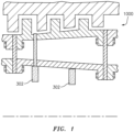
- Borescope plugs may be installed in multiple locations within the engine to permit borescope access once the borescope plug is removed (see, e.g., FIG. 1 ).
- the location of borescope plugs may be inconvenient to technicians seeking to remove or install the plugs.
- removal or installation of the borescope plug may be a "blind operation" (i.e., the technician can physically reach the borescope plug but, based on the plugs location, cannot visually observe the plug during the removal or installation).
- borescope systems comprising a borescope plug port, a borescope plug and a borescope tool are disclosed in patent applications US2015125267A1 , US3936217A and US 2018017466A1 .
- a borescope plug system as claimed in claim 1 and a method for operating a borescope plug as claimed in claim 7.
- Various embodiments are set out in the dependent claims.
- a gas turbine engine may include one or more borescope plug ports to facilitate inspection of gas turbine engine internal components using a borescope.
- Each of the borescope plug ports may be configured for receipt of a borescope plug configured to seal the respective borescope plug port.
- a borescope plug of a respective borescope plug port may be removed to facilitate inspection of gas turbine engine internal components by a technician.
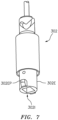
- a borescope plug, such as borescope plug 302 as depicted in FIG. 7 is configured to be securely engaged within a borescope plug port, such as borescope plug port 300 as depicted in FIG. 2A .
- the borescope plug 302 may be secured within the borescope plug port 300 using, for example, complementary mating engagement with threads formed in the borescope plug port 300 or, alternatively, lugs or lug-receiving slots formed in the borescope plug 302 for twist-lock engagement with corresponding lugs or slots formed in a complimentary borescope plug port 300. Any known form of plug/port retention mechanisms may be utilized in connection with the borescope plug 302 and borescope plug port 300.
- the guiding sleeve 200 includes a body 202 having a first sleeve end 202E1, a second sleeve end 202E2, and an internal passage 204.
- the internal passage 204 extends between the first sleeve end 202E1 and the second sleeve end 202E2 along a longitudinally extending centerline 202CL.
- the body 202 may have, for example, a substantially cylindrical shape.
- the guiding sleeve 200 is configured to engage an adapter 304 of the borescope plug port 300 so as to guide a borescope plug 302 to or from the borescope plug port 300 during a respective installation or removal of the borescope plug 302 from the borescope plug port 300. While the exemplary guiding sleeve 200, as shown in FIGS. 2A-2C , is described with respect to use in aircraft gas turbine engines, the guiding sleeve 200 is not limited to use in aircraft and may be used with other engine types and configurations in other categories of vehicles. Furthermore, the guiding sleeve 200 may be used to facilitate borescope plug installation and removal in non-vehicle machinery (e.g., a turbine generator).
- non-vehicle machinery e.g., a turbine generator
- the first sleeve end 202E1 of the guiding sleeve 200 is configured to engage the adapter 304 of the borescope plug port 300 so as to provide secure alignment between the guiding sleeve 200 and the borescope plug port 300 while permitting access to the borescope plug 302 (not shown) of the borescope plug port 300 via the internal passage 204 of the guiding sleeve 200.
- Proper engagement between the guiding sleeve 200 and the borescope plug port 300 may be accomplished by, for example, twist-lock engagement between one or more slots 202E1S of the first sleeve end 202E1 and one or more pins 304P of the adapter 304.
- proper engagement between the first sleeve end 202E1 and the adapter 304 may be accomplished by any suitable method, such as threaded engagement.
- the length and/or width of the guiding sleeve 200 may vary depending on the characteristics of the relevant machinery (e.g., the gas turbine engine), for example, the size of the borescope plug 302 and the distance to the borescope plug 302 from a technician's access point.
- the guiding sleeve 200 may be made from any sufficiently rigid material, such as metal or plastic, to ensure proper engagement with the adapter 304 and access to the borescope plug 302 via the internal passage 204 of the guiding sleeve 200.
- the guiding sleeve 200 may be made from a plurality of materials.
- the first sleeve end 202E1 may be made from metal to facilitate secure engagement with the adapter 304 while the body 202 of the guiding sleeve 200 may be made from a second material, such as plastic.
- the guiding sleeve 200 may include both rigid and non-rigid materials.
- the first sleeve end 202E1 may be made from metal to facilitate secure engagement with the adapter 304 while the body 202 of the guiding sleeve 200 may be made from a second non-rigid material, such as fabric or flexible plastic hose.
- engagement of the guiding sleeve 200 with the borescope plug port 300 may facilitate operation of the borescope plug 302 (not shown) by a tool, such as driver 104, via the internal passage 204 of the guiding sleeve 200.
- Driver 104 includes a first driver end 104E1 (not shown, substantially similar to 404E1 as shown in FIG. 8 ) and a second driver end 104E2. Additionally, driver 104 may be a standard square driver, or any other driver configured to install or remove a borescope plug 302. As will be discussed in greater detail, other tools may be used for installation and removal of the borescope plug 302.
- the alignment of the guiding sleeve 200 with the borescope plug port 300 may also facilitate engagement between the driver 104 and the borescope plug 302 by directing the driver 104 towards the borescope plug 302 (e.g., a technician attempting to blindly remove a borescope plug 302).
- the following non-limiting method is provided to illustrate how the guiding sleeve 200 according to aspects of the present disclosure may facilitate borescope plug 302 installation and removal.
- a technician may direct the guiding sleeve 200 towards the borescope plug port aligning the one or more slots 202E1S of the first sleeve end 202E1 with the one or more pins 304P of the adapter 304.
- the guiding sleeve 200 is engaged with the borescope plug port 300 by twisting the guiding sleeve 200, in direction R3 for example (i.e., counter-clockwise), to establish twist-lock engagement between the first sleeve end 202E1 and the adapter 304.
- a tool such as driver 104, is inserted into the internal passage 204 of the guiding sleeve 200 to engage the borescope plug 302, such as by engaging an interior surface 302I (not shown) of the borescope plug 302.
- Driver 104 is rotated clockwise or counter-clockwise as necessary to install or remove the borescope plug 302.
- the driver 104 is removed from the internal passage 204 of the guiding sleeve 200 along with the borescope plug 302 (if removing the borescope plug).
- the guiding sleeve 200 is then removed from the borescope plug port using a twist motion in a direction opposite that of the installation, in direction R4 for example (i.e., clockwise).
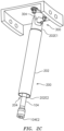
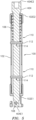
- the borescope plug tool 100 generally includes a housing 102, a driver 404, and a spring 106.
- the borescope plug tool 100 and the guiding sleeve 200 may provide a common interface to effect installation or removal of a borescope plug 302 from a borescope plug port 300.
- the borescope plug tool 100 may be used independent of the guiding sleeve 200 to effect installation or removal of a borescope plug 302 from a borescope plug port 300.
- the housing 102 includes a first housing end 102E1, a second housing end 102E2, and a longitudinally extending centerline 102CL extending between the first housing end 102E1 and the second housing end 102E2.
- the driver 404 includes a first driver end 404E1 and a second driver end 404E2.
- Driver 404 is disposed at least partially within the housing 102 along the longitudinally extending centerline 102CL, with the first driver end 404E1 and the second driver end 404E2 having an orientation corresponding to the respective first housing end 102E1 and second housing end 102E2.
- Spring 106 is disposed within the housing 102 and couples the housing 102 to the driver 404.
- the driver 404 is configured to move within the housing 102 along the longitudinally extending centerline 102CL to engage the borescope plug 302 of the borescope plug port 300, such as by engaging the first driver end 404E1 with an interior surface 302I of the borescope plug 302.
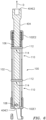
- the second driver end 404E2 of the driver 404 may be pulled in direction D, against a force of the spring 106, into a retracted position (see FIG. 6 ) to facilitate engagement between the borescope plug tool 100 and the borescope plug 302.
- the force of the spring 106 will return the driver 404 to its nominal position (see FIGS. 3-5 ).
- the first housing end 102E1 is configured to engage the borescope plug 302, such as by engaging an exterior surface 302E, to secure the borescope plug 302 to the borescope plug tool 100.
- Proper engagement between the first housing end 102E1 of the housing 102 and the borescope plug 300 is accomplished by twist-lock engagement between one or more slots 102E1S of the first housing end 102E1 and one or more pins 302EP of the borescope plug 302.
- proper engagement between the first housing end 102E1 and the borescope plug 302 may be accomplished by any suitable method, such as threaded engagement.
- first housing end 102E1 and the second housing end 102E2 are removable from the housing 102.
- One or both of the first housing end 102E1 and the second housing end 102E2 may be coupled to the housing by, for example, threaded engagement or any other suitable method. Removal of one or both of the first housing end 102E1 and the second housing end 102E2 may facilitate multiple configurations of the borescope plug tool 100.
- the second housing end 102E2 may be removed to allow an alternative driver (e.g., one having a different sized or shaped engagement surface), other than driver 404, to be installed in the borescope plug tool 100.
- the driver 404 may engage the borescope plug 302 when released from the retracted position to the nominal position within the housing 102.
- driver 404 may be a standard square driver, or any other driver configured to install or remove a borescope plug 302.
- the driver 104, 404 may include at least one spring-loaded ball 108 disposed on the first driver end 104E1, 404E1 (see FIG. 5 ).
- the at least one spring-loaded ball and a corresponding at least one recess 302F, disposed on the interior surface 302I of the borescope plug 302 (see FIG. 9 ) may operate together to provide more secure engagement between the first driver end 104E1, 404E1 and the borescope plug 302.
- the housing 102 may include at least one guide aperture 110 and the driver 404 may include a respective at least one guide pin 112 located within the at least one guide aperture 110 and configured to travel longitudinally within the at least one guide aperture 110.
- the at least one guide pin 112 may be disposed within a respective at least one pin aperture 114 extending through the driver 404 in a radial direction with respect to the longitudinally extending centerline 102CL (see FIG. 6 ).
- the orientation of the at least one guide pin 112 within the respective at least one guide aperture 110 substantially prevents relative motion between the housing 102 and the driver 404 with respect to the longitudinally extending centerline 102CL.
- rotation of the driver 404 in direction R1, R2 about the longitudinally extending centerline 102CL will effect a similar rotation of the housing 102 about the longitudinally extending centerline 102CL, and vice versa.
- This alignment between the housing 102 and the driver 404 facilitates engagement of the housing 102 with the borescope plug 302 when removing the borescope plug 302 (i.e., the rotational motion of the driver 404 required to remove the borescope plug 302 is the same rotational motion of the housing 102 required to engage and secure the borescope plug 302).
- the at least one guide aperture 110 and respective at least one guide pin 112 facilitate proper engagement of the driver 404 with the borescope plug 302 by providing the technician with visual and/or haptic feedback of the driver 404 position.
- the at least one guide pin 112 may be oriented at a substantially forward-most (i.e., towards the borescope plug 302) longitudinal position within the respective at least one guide aperture 110. Additionally, in some embodiments, one of the at least one guide pins 112 may be in communication with the spring 106 so as to provide compressive force to the spring 106 when the driver 404 is pulled in direction D.
- the borescope plug tool 100 may facilitate borescope plug 302 installation and removal.
- a technician may direct the borescope plug tool 100 towards the borescope plug 302 and align the one or more slots 102E1S of the first housing end 102E1 with the one or more pins 302EP of the borescope plug 302 while pulling the driver 404 in direction D into a retracted position against the force of the spring 106 (see FIG. 6 ).
- misalignment between the borescope plug 302 and the first driver end 404E1 may push the driver 404 into the retracted position, thus, it may be unnecessary for the technician to pull the driver 404 in direction D.
- driver 404 is in a retracted position, the housing 102 is engaged with the borescope plug 302 by rotating the housing 102 or the driver 104, in direction R2 for example (i.e., counter-clockwise), to establish twist-lock engagement between the first housing end 102E1 and the exterior surface 302E of the borescope plug 302.
- Driver 404 is then released, causing the spring 106 force to return the driver 404 to the nominal position, thereby engaging the first driver end 104E1 with the interior surface 302I of the borescope plug 302 (see FIG. 9 ).
- the housing 102 or the driver 404 in direction R2, will apply a torque to the borescope plug 302 with respect to the borescope plug port 300, thus rotating and subsequently disengaging the borescope plug 302 from the borescope port 300.
- Installation of a borescope plug 302 into a borescope plug port 300 may be accomplished in a manner similar to that discussed above with respect to removal of the borescope plug 302.
- the borescope plug 302 is secured to the housing 102 by directing the borescope plug tool 100 towards the borescope plug 302 and aligning the one or more slots 102E1S of the first housing end 102E1 with the one or more pins 302EP of the borescope plug 302 while pulling the driver 404 in direction D into a retracted position against the force of the spring 106 (see FIG. 6 ).
- driver 404 While driver 404 is in a retracted position, the housing 102 is engaged with the borescope plug 302 by rotating the housing 102 or the driver 104, in direction R2 for example, to establish twist-lock engagement between the first housing end 102E1 and the exterior surface 302E of the borescope plug 302.
- Driver 404 is then released, causing the spring 106 force to return the driver 404 to the nominal position, thereby engaging the first driver end 404E1 with the interior surface 302I of the borescope plug 302 (see FIG. 9 ).
- the borescope plug 302 is inserted into the borescope plug port 300.
- Rotating the housing 102 or the driver 404 in direction R1 while pulling the driver 404 in direction D into a retracted position against the force of the spring 106 will disengage the first housing end 102E1 of the borescope plug tool 100 from the borescope plug 302.
- installation or removal of a borescope plug 302, as described above with respect to operation of one or more of the guiding sleeve 200, driver 104, and borescope plug tool 100 can be accomplished by a technician using a single hand.
- the present disclosure as described herein includes several aspects and embodiments that include particular features. Although these particular features may be described individually, some or all of these features may be combined with any one of the aspects as long as they remain within the scope of the claims. Accordingly, the present disclosure is not to be restricted except in light of the attached claims.
Landscapes
- Engineering & Computer Science (AREA)
- Physics & Mathematics (AREA)
- Mechanical Engineering (AREA)
- General Engineering & Computer Science (AREA)
- General Physics & Mathematics (AREA)
- Astronomy & Astrophysics (AREA)
- Optics & Photonics (AREA)
- Chemical & Material Sciences (AREA)
- Combustion & Propulsion (AREA)
- Instruments For Viewing The Inside Of Hollow Bodies (AREA)
- Endoscopes (AREA)
Claims (10)
- Système de bouchon d'endoscope comprenant :un port de prise de bouchon d'endoscope (300) comportant un bouchon d'endoscope (302), dans lequel le bouchon d'endoscope (302) est configuré pour être solidement en contact avec le port de prise de bouchon d'endoscope (300) ; etun outil de bouchon d'endoscope (100), l'outil comprenant :un boîtier (102) comprenant une première extrémité de boîtier (102E1) et une seconde extrémité de boîtier (102E2), le boîtier (102) comprenant également une ligne centrale se prolongeant longitudinalement (102CL) se prolongeant entre la première extrémité de boîtier (102E1) et la seconde extrémité de boîtier (102E2);un conducteur (404) disposé au moins partiellement à l'intérieur du boîtier (102) le long de la ligne centrale se prolongeant longitudinalement (102CL) et comprenant une première extrémité d'entraînement (404E1) et une seconde extrémité d'entraînement (404E2), la première extrémité d'entraînement (404E1) et la seconde extrémité d'entraînement (404E2) ayant une orientation correspondant à la première extrémité de boîtier (102E1) et à la seconde extrémité de boîtier (102E2) respectivement ; etun ressort (106), disposé à l'intérieur du boîtier (102), et couplant le boîtier (102) au conducteur (404) ;dans lequel le conducteur (404) est configuré pour se déplacer à l'intérieur du boîtier (102), le long de la ligne centrale se prolongeant longitudinalement (102CL), pour faire entrer la première extrémité du conducteur (404E1) en contact avec le bouchon d'endoscope (302) du port de prise de bouchon d'endoscope (300), et pour installer ou retirer le bouchon d'endoscope (302) du port de prise de bouchon d'endoscope (300) sur la base d'une rotation du conducteur (404) autour de la ligne centrale se prolongeant longitudinalement (102CL), et dans lequel la première extrémité de boîtier (102E1) est configurée pour faire entrer le bouchon d'endoscope (302) en contact avec une ou plusieurs fentes (102E1S) de la première extrémité de boîtier (102E1) pour fixer le bouchon d'endoscope (302) à l'outil de bouchon d'endoscope (100), dans lequel un engagement approprié entre la première extrémité de boîtier (102E1) du boîtier (102) et le bouchon d'endoscope (300) est configuré pour être accompli par un engagement à verrouillage par rotation entre la ou les fentes (102E1S) de la première extrémité de boîtier (102E1) et une ou plusieurs broches (302EP) du bouchon d'endoscope (302).
- Système selon la revendication 1, dans lequel le conducteur (404) est un conducteur carré standard.
- Système selon la revendication 1 ou 2, dans lequel la première extrémité d'entraînement (404E1) comprend au moins une bille à ressort.
- Système selon une quelconque revendication précédente, dans lequel le boîtier (102) comprend au moins une ouverture de guidage (110) et le conducteur (404) comprend au moins une broche de guidage (112), la ou les broches de guidage (112) étant situées à l'intérieur d'au moins une ouverture de guidage (110) respective et configurées pour se déplacer longitudinalement à l'intérieur d'au moins une ouverture de guidage (110) respective.
- Système selon la revendication 4, dans lequel un emplacement de la ou des broches de guidage (112) à l'intérieur de la ou des ouvertures de guidage respectives (110) empêche la rotation du conducteur (404) autour de la ligne centrale se prolongeant longitudinalement (102CL) par rapport au boîtier (102).
- Système selon l'une quelconque des revendications précédentes, comprenant également un manchon de guidage (200) comprenant un corps (202) comportant une première extrémité de manchon (202E1), une seconde extrémité de manchon (202E2) et un passage interne (204) se prolongeant longitudinalement entre la première extrémité de manchon (202E1) et la seconde extrémité de manchon (202E2), dans lequel le manchon de guidage (200) est configuré pour entrer en contact avec un adaptateur (304) du port de prise de bouchon d'endoscope (300) et pour entourer au moins partiellement le boîtier (102) dans le passage interne (204) .
- Procédé de fonctionnement d'un bouchon d'endoscope (302) comprenant :fourniture d'un boîtier (102) comprenant une première extrémité de boîtier (102E1) et une seconde extrémité de boîtier (102E2), le boîtier (102) comprenant également une ligne centrale se prolongeant longitudinalement (102CL) se prolongeant entre la première extrémité de boîtier (102E1) et la seconde extrémité de boîtier (102E2) ;fourniture d'un conducteur (404) disposé au moins partiellement à l'intérieur du boîtier (102) le long de la ligne centrale se prolongeant longitudinalement (102CL) et comprenant une première extrémité d'entraînement (404E1) et une seconde extrémité d'entraînement (404E2), la première extrémité d'entraînement (404E1) et la seconde extrémité d'entraînement (404E2) ayant une orientation correspondant à la première extrémité de boîtier (102E1) et à la seconde extrémité de boîtier (102E2) respectivement ; etfourniture d'un ressort (106), disposé à l'intérieur du boîtier (102), et couplant le boîtier (102) au conducteur (404) ;le fait de faire entrer la première extrémité d'entraînement (104E1) en contact avec un bouchon d'endoscope (302) d'un port de prise de bouchon d'endoscope (300) en déplaçant le conducteur (404) à l'intérieur du boîtier (102) le long de la ligne centrale se prolongeant longitudinalement (102CL) ;le fait de faire tourner le conducteur (404) autour de la ligne centrale se prolongeant longitudinalement (102CL) pour installer ou retirer le bouchon de l'endoscope (302) du port de prise du bouchon de l'endoscope (300) ; etle fait de faire entrer la première extrémité du boîtier (102E1) en contact avec le bouchon d'endoscope (302) par engagement à verrouillage par rotation entre une ou plusieurs fentes (102E1S) de la première extrémité du boîtier (102E1) et une ou plusieurs broches (302EP) du bouchon d'endoscope (302).
- Procédé selon la revendication 7, dans lequel le conducteur (404) est un conducteur carré standard.
- Procédé selon la revendication 7 ou 8, dans lequel la première extrémité d'entraînement (404E1) comprend au moins une bille à ressort.
- Procédé selon la revendication 7, 8 ou 9, dans lequel le boîtier (102) comprend au moins une ouverture de guidage (110) et le conducteur (404) comprend au moins une broche de guidage (112), la ou les broches de guidage (112) étant situées à l'intérieur d'au moins une ouverture de guidage (110) respective et configurées pour se déplacer longitudinalement à l'intérieur d'au moins une ouverture de guidage (110) respective, dans lequel un emplacement de la ou des broches de guidage (112) à l'intérieur d'au moins une ouverture de guidage (110) respective empêche éventuellement la rotation du conducteur (404) autour de la ligne centrale se prolongeant longitudinalement (102CL) par rapport au boîtier (102).
Applications Claiming Priority (1)
| Application Number | Priority Date | Filing Date | Title |
|---|---|---|---|
| US16/151,795 US11085322B2 (en) | 2018-10-04 | 2018-10-04 | Borescope plug system |
Publications (2)
| Publication Number | Publication Date |
|---|---|
| EP3657230A1 EP3657230A1 (fr) | 2020-05-27 |
| EP3657230B1 true EP3657230B1 (fr) | 2024-11-27 |
Family
ID=67551062
Family Applications (1)
| Application Number | Title | Priority Date | Filing Date |
|---|---|---|---|
| EP19189820.4A Active EP3657230B1 (fr) | 2018-10-04 | 2019-08-02 | Système de bouchon d'endoscope |
Country Status (2)
| Country | Link |
|---|---|
| US (1) | US11085322B2 (fr) |
| EP (1) | EP3657230B1 (fr) |
Families Citing this family (2)
| Publication number | Priority date | Publication date | Assignee | Title |
|---|---|---|---|---|
| US11624294B1 (en) * | 2021-12-21 | 2023-04-11 | Raytheon Technologies Corporation | Restraining plug |
| FR3165036A1 (fr) * | 2024-07-29 | 2026-01-30 | Safran Aircraft Engines | Dispositif d'obturation d'une ouverture realisée dans une pièce aérodynamique |
Citations (3)
| Publication number | Priority date | Publication date | Assignee | Title |
|---|---|---|---|---|
| US3936217A (en) * | 1975-01-31 | 1976-02-03 | Westinghouse Electric Corporation | Inspection port for turbines |
| US20150125267A1 (en) * | 2013-11-04 | 2015-05-07 | Clifford Hatcher, JR. | Standardized gas turbine inspection port system |
| US20180017466A1 (en) * | 2014-09-18 | 2018-01-18 | General Electric Company | Systems and methods for attaching a probe to a casing of a gas turbine engine |
Family Cites Families (9)
| Publication number | Priority date | Publication date | Assignee | Title |
|---|---|---|---|---|
| US3157258A (en) * | 1961-06-16 | 1964-11-17 | Vincent G Dreesman | Torque limiting coupling and positive clutch mechanism |
| US4591794A (en) * | 1982-12-28 | 1986-05-27 | United Technologies Corporation | Gas turbine access port plug electrostatic probe |
| US5690006A (en) * | 1996-05-21 | 1997-11-25 | Pulliam; Doyle H. | Infinitely slide-adjustable socket extender for socket wrenches |
| US5867976A (en) * | 1997-08-01 | 1999-02-09 | General Electric Company | Self-retained borescope plug |
| TWM299055U (en) | 2006-03-20 | 2006-10-11 | Tien I Ind Co Ltd | Fast-rotating structure of hand tool handle |
| CN102235501B (zh) | 2010-05-05 | 2013-11-27 | 中国航空工业集团公司沈阳发动机设计研究所 | 一种能反复拆装的通道密封装置 |
| US8505418B1 (en) | 2012-08-17 | 2013-08-13 | Wen Hung Chiang | Tool extension |
| WO2018034986A1 (fr) | 2016-08-17 | 2018-02-22 | Omg, Inc. | Adaptateur pour outil d'installation d'élément de fixation |
| US10821583B2 (en) | 2017-03-24 | 2020-11-03 | Raytheon Technologies Corporation | Spring loaded pilot punch assembly |
-
2018
- 2018-10-04 US US16/151,795 patent/US11085322B2/en active Active
-
2019
- 2019-08-02 EP EP19189820.4A patent/EP3657230B1/fr active Active
Patent Citations (3)
| Publication number | Priority date | Publication date | Assignee | Title |
|---|---|---|---|---|
| US3936217A (en) * | 1975-01-31 | 1976-02-03 | Westinghouse Electric Corporation | Inspection port for turbines |
| US20150125267A1 (en) * | 2013-11-04 | 2015-05-07 | Clifford Hatcher, JR. | Standardized gas turbine inspection port system |
| US20180017466A1 (en) * | 2014-09-18 | 2018-01-18 | General Electric Company | Systems and methods for attaching a probe to a casing of a gas turbine engine |
Also Published As
| Publication number | Publication date |
|---|---|
| US20200109641A1 (en) | 2020-04-09 |
| US11085322B2 (en) | 2021-08-10 |
| EP3657230A1 (fr) | 2020-05-27 |
Similar Documents
| Publication | Publication Date | Title |
|---|---|---|
| EP2912361B1 (fr) | Ensemble raccord rapide multiple sous-marin | |
| AU605225B2 (en) | Self-aligning electrical connector | |
| US12266888B2 (en) | Subsea connector | |
| US20160245441A1 (en) | Connector, releasing tool, set comprising connector and releasing tool | |
| US4645368A (en) | Quick disconnect mechanism for selectively securing a shaft to a power take-off end yoke | |
| EP2584243B1 (fr) | Raccord | |
| EP3657230A1 (fr) | Système de bouchon d'endoscope | |
| US20150167880A1 (en) | Coupling and clip for coupling | |
| US8550167B2 (en) | Remote operated vehicle interface with overtorque protection | |
| SE533221C2 (sv) | Anslutningsanordning för medialedningar | |
| US8991023B2 (en) | PTC fitting cartridge | |
| US8845275B2 (en) | Cranking pad interlock | |
| US9778144B2 (en) | Systems and methods for attaching a probe to a casing of a gas turbine engine | |
| US9033050B2 (en) | ROV drive bucket plug | |
| EP4274980B1 (fr) | Raccord de tube de câble à fibres optiques de réduction | |
| US10605012B2 (en) | Drop in anti-rotation key | |
| CN110513376A (zh) | 一种快速对接锁紧机构 | |
| CN110220058B (zh) | 一种流体连接器组件及其连接器、适配连接器 | |
| US7192062B2 (en) | Quick connect cartridge assembly with plug | |
| WO2019096385A1 (fr) | Ensemble raccord de tuyau | |
| EP3209895A1 (fr) | Raccord à rotule | |
| CN105460226A (zh) | 用于联接件和锥套组件的快速释放系统 | |
| US20100233904A1 (en) | Electrical connector with releasable locking clip | |
| US5642754A (en) | Method of securing a valve seat member within a tubular housing and a ball valve assembly | |
| US10415687B1 (en) | Transmission adapter apparatus and method |
Legal Events
| Date | Code | Title | Description |
|---|---|---|---|
| PUAI | Public reference made under article 153(3) epc to a published international application that has entered the european phase |
Free format text: ORIGINAL CODE: 0009012 |
|
| STAA | Information on the status of an ep patent application or granted ep patent |
Free format text: STATUS: THE APPLICATION HAS BEEN PUBLISHED |
|
| AK | Designated contracting states |
Kind code of ref document: A1 Designated state(s): AL AT BE BG CH CY CZ DE DK EE ES FI FR GB GR HR HU IE IS IT LI LT LU LV MC MK MT NL NO PL PT RO RS SE SI SK SM TR |
|
| AX | Request for extension of the european patent |
Extension state: BA ME |
|
| STAA | Information on the status of an ep patent application or granted ep patent |
Free format text: STATUS: REQUEST FOR EXAMINATION WAS MADE |
|
| 17P | Request for examination filed |
Effective date: 20201127 |
|
| RBV | Designated contracting states (corrected) |
Designated state(s): AL AT BE BG CH CY CZ DE DK EE ES FI FR GB GR HR HU IE IS IT LI LT LU LV MC MK MT NL NO PL PT RO RS SE SI SK SM TR |
|
| RAP1 | Party data changed (applicant data changed or rights of an application transferred) |
Owner name: RAYTHEON TECHNOLOGIES CORPORATION |
|
| STAA | Information on the status of an ep patent application or granted ep patent |
Free format text: STATUS: EXAMINATION IS IN PROGRESS |
|
| 17Q | First examination report despatched |
Effective date: 20220706 |
|
| RAP3 | Party data changed (applicant data changed or rights of an application transferred) |
Owner name: RTX CORPORATION |
|
| GRAP | Despatch of communication of intention to grant a patent |
Free format text: ORIGINAL CODE: EPIDOSNIGR1 |
|
| STAA | Information on the status of an ep patent application or granted ep patent |
Free format text: STATUS: GRANT OF PATENT IS INTENDED |
|
| RIC1 | Information provided on ipc code assigned before grant |
Ipc: B25B 13/48 20060101ALI20240606BHEP Ipc: B25B 23/00 20060101ALI20240606BHEP Ipc: B25B 13/50 20060101ALI20240606BHEP Ipc: G01N 21/954 20060101ALI20240606BHEP Ipc: G02B 23/24 20060101AFI20240606BHEP |
|
| INTG | Intention to grant announced |
Effective date: 20240625 |
|
| GRAS | Grant fee paid |
Free format text: ORIGINAL CODE: EPIDOSNIGR3 |
|
| GRAA | (expected) grant |
Free format text: ORIGINAL CODE: 0009210 |
|
| STAA | Information on the status of an ep patent application or granted ep patent |
Free format text: STATUS: THE PATENT HAS BEEN GRANTED |
|
| AK | Designated contracting states |
Kind code of ref document: B1 Designated state(s): AL AT BE BG CH CY CZ DE DK EE ES FI FR GB GR HR HU IE IS IT LI LT LU LV MC MK MT NL NO PL PT RO RS SE SI SK SM TR |
|
| REG | Reference to a national code |
Ref country code: GB Ref legal event code: FG4D |
|
| REG | Reference to a national code |
Ref country code: CH Ref legal event code: EP |
|
| REG | Reference to a national code |
Ref country code: IE Ref legal event code: FG4D |
|
| REG | Reference to a national code |
Ref country code: DE Ref legal event code: R096 Ref document number: 602019062495 Country of ref document: DE |
|
| REG | Reference to a national code |
Ref country code: LT Ref legal event code: MG9D |
|
| REG | Reference to a national code |
Ref country code: NL Ref legal event code: MP Effective date: 20241127 |
|
| PG25 | Lapsed in a contracting state [announced via postgrant information from national office to epo] |
Ref country code: HR Free format text: LAPSE BECAUSE OF FAILURE TO SUBMIT A TRANSLATION OF THE DESCRIPTION OR TO PAY THE FEE WITHIN THE PRESCRIBED TIME-LIMIT Effective date: 20241127 Ref country code: IS Free format text: LAPSE BECAUSE OF FAILURE TO SUBMIT A TRANSLATION OF THE DESCRIPTION OR TO PAY THE FEE WITHIN THE PRESCRIBED TIME-LIMIT Effective date: 20250327 Ref country code: PT Free format text: LAPSE BECAUSE OF FAILURE TO SUBMIT A TRANSLATION OF THE DESCRIPTION OR TO PAY THE FEE WITHIN THE PRESCRIBED TIME-LIMIT Effective date: 20250327 |
|
| PG25 | Lapsed in a contracting state [announced via postgrant information from national office to epo] |
Ref country code: NL Free format text: LAPSE BECAUSE OF FAILURE TO SUBMIT A TRANSLATION OF THE DESCRIPTION OR TO PAY THE FEE WITHIN THE PRESCRIBED TIME-LIMIT Effective date: 20241127 Ref country code: FI Free format text: LAPSE BECAUSE OF FAILURE TO SUBMIT A TRANSLATION OF THE DESCRIPTION OR TO PAY THE FEE WITHIN THE PRESCRIBED TIME-LIMIT Effective date: 20241127 |
|
| REG | Reference to a national code |
Ref country code: AT Ref legal event code: MK05 Ref document number: 1746226 Country of ref document: AT Kind code of ref document: T Effective date: 20241127 |
|
| PG25 | Lapsed in a contracting state [announced via postgrant information from national office to epo] |
Ref country code: BG Free format text: LAPSE BECAUSE OF FAILURE TO SUBMIT A TRANSLATION OF THE DESCRIPTION OR TO PAY THE FEE WITHIN THE PRESCRIBED TIME-LIMIT Effective date: 20241127 |
|
| PG25 | Lapsed in a contracting state [announced via postgrant information from national office to epo] |
Ref country code: ES Free format text: LAPSE BECAUSE OF FAILURE TO SUBMIT A TRANSLATION OF THE DESCRIPTION OR TO PAY THE FEE WITHIN THE PRESCRIBED TIME-LIMIT Effective date: 20241127 |
|
| PG25 | Lapsed in a contracting state [announced via postgrant information from national office to epo] |
Ref country code: NO Free format text: LAPSE BECAUSE OF FAILURE TO SUBMIT A TRANSLATION OF THE DESCRIPTION OR TO PAY THE FEE WITHIN THE PRESCRIBED TIME-LIMIT Effective date: 20250227 |
|
| PG25 | Lapsed in a contracting state [announced via postgrant information from national office to epo] |
Ref country code: LV Free format text: LAPSE BECAUSE OF FAILURE TO SUBMIT A TRANSLATION OF THE DESCRIPTION OR TO PAY THE FEE WITHIN THE PRESCRIBED TIME-LIMIT Effective date: 20241127 Ref country code: AT Free format text: LAPSE BECAUSE OF FAILURE TO SUBMIT A TRANSLATION OF THE DESCRIPTION OR TO PAY THE FEE WITHIN THE PRESCRIBED TIME-LIMIT Effective date: 20241127 Ref country code: GR Free format text: LAPSE BECAUSE OF FAILURE TO SUBMIT A TRANSLATION OF THE DESCRIPTION OR TO PAY THE FEE WITHIN THE PRESCRIBED TIME-LIMIT Effective date: 20250228 |
|
| PG25 | Lapsed in a contracting state [announced via postgrant information from national office to epo] |
Ref country code: PL Free format text: LAPSE BECAUSE OF FAILURE TO SUBMIT A TRANSLATION OF THE DESCRIPTION OR TO PAY THE FEE WITHIN THE PRESCRIBED TIME-LIMIT Effective date: 20241127 |
|
| PG25 | Lapsed in a contracting state [announced via postgrant information from national office to epo] |
Ref country code: RS Free format text: LAPSE BECAUSE OF FAILURE TO SUBMIT A TRANSLATION OF THE DESCRIPTION OR TO PAY THE FEE WITHIN THE PRESCRIBED TIME-LIMIT Effective date: 20250227 |
|
| PG25 | Lapsed in a contracting state [announced via postgrant information from national office to epo] |
Ref country code: SM Free format text: LAPSE BECAUSE OF FAILURE TO SUBMIT A TRANSLATION OF THE DESCRIPTION OR TO PAY THE FEE WITHIN THE PRESCRIBED TIME-LIMIT Effective date: 20241127 |
|
| PG25 | Lapsed in a contracting state [announced via postgrant information from national office to epo] |
Ref country code: DK Free format text: LAPSE BECAUSE OF FAILURE TO SUBMIT A TRANSLATION OF THE DESCRIPTION OR TO PAY THE FEE WITHIN THE PRESCRIBED TIME-LIMIT Effective date: 20241127 |
|
| PG25 | Lapsed in a contracting state [announced via postgrant information from national office to epo] |
Ref country code: EE Free format text: LAPSE BECAUSE OF FAILURE TO SUBMIT A TRANSLATION OF THE DESCRIPTION OR TO PAY THE FEE WITHIN THE PRESCRIBED TIME-LIMIT Effective date: 20241127 |
|
| PG25 | Lapsed in a contracting state [announced via postgrant information from national office to epo] |
Ref country code: RO Free format text: LAPSE BECAUSE OF FAILURE TO SUBMIT A TRANSLATION OF THE DESCRIPTION OR TO PAY THE FEE WITHIN THE PRESCRIBED TIME-LIMIT Effective date: 20241127 |
|
| PG25 | Lapsed in a contracting state [announced via postgrant information from national office to epo] |
Ref country code: SK Free format text: LAPSE BECAUSE OF FAILURE TO SUBMIT A TRANSLATION OF THE DESCRIPTION OR TO PAY THE FEE WITHIN THE PRESCRIBED TIME-LIMIT Effective date: 20241127 |
|
| PG25 | Lapsed in a contracting state [announced via postgrant information from national office to epo] |
Ref country code: CZ Free format text: LAPSE BECAUSE OF FAILURE TO SUBMIT A TRANSLATION OF THE DESCRIPTION OR TO PAY THE FEE WITHIN THE PRESCRIBED TIME-LIMIT Effective date: 20241127 |
|
| PG25 | Lapsed in a contracting state [announced via postgrant information from national office to epo] |
Ref country code: IT Free format text: LAPSE BECAUSE OF FAILURE TO SUBMIT A TRANSLATION OF THE DESCRIPTION OR TO PAY THE FEE WITHIN THE PRESCRIBED TIME-LIMIT Effective date: 20241127 |
|
| REG | Reference to a national code |
Ref country code: DE Ref legal event code: R097 Ref document number: 602019062495 Country of ref document: DE |
|
| PG25 | Lapsed in a contracting state [announced via postgrant information from national office to epo] |
Ref country code: SE Free format text: LAPSE BECAUSE OF FAILURE TO SUBMIT A TRANSLATION OF THE DESCRIPTION OR TO PAY THE FEE WITHIN THE PRESCRIBED TIME-LIMIT Effective date: 20241127 |
|
| PLBE | No opposition filed within time limit |
Free format text: ORIGINAL CODE: 0009261 |
|
| STAA | Information on the status of an ep patent application or granted ep patent |
Free format text: STATUS: NO OPPOSITION FILED WITHIN TIME LIMIT |
|
| REG | Reference to a national code |
Ref country code: CH Ref legal event code: L10 Free format text: ST27 STATUS EVENT CODE: U-0-0-L10-L00 (AS PROVIDED BY THE NATIONAL OFFICE) Effective date: 20251008 |
|
| PGFP | Annual fee paid to national office [announced via postgrant information from national office to epo] |
Ref country code: DE Payment date: 20250724 Year of fee payment: 7 |
|
| PGFP | Annual fee paid to national office [announced via postgrant information from national office to epo] |
Ref country code: GB Payment date: 20250724 Year of fee payment: 7 |
|
| PGFP | Annual fee paid to national office [announced via postgrant information from national office to epo] |
Ref country code: FR Payment date: 20250725 Year of fee payment: 7 |
|
| 26N | No opposition filed |
Effective date: 20250828 |
|
| REG | Reference to a national code |
Ref country code: CH Ref legal event code: H13 Free format text: ST27 STATUS EVENT CODE: U-0-0-H10-H13 (AS PROVIDED BY THE NATIONAL OFFICE) Effective date: 20260324 |
|
| PG25 | Lapsed in a contracting state [announced via postgrant information from national office to epo] |
Ref country code: MC Free format text: LAPSE BECAUSE OF FAILURE TO SUBMIT A TRANSLATION OF THE DESCRIPTION OR TO PAY THE FEE WITHIN THE PRESCRIBED TIME-LIMIT Effective date: 20241127 |
|
| PG25 | Lapsed in a contracting state [announced via postgrant information from national office to epo] |
Ref country code: LU Free format text: LAPSE BECAUSE OF NON-PAYMENT OF DUE FEES Effective date: 20250802 |
|
| PG25 | Lapsed in a contracting state [announced via postgrant information from national office to epo] |
Ref country code: CH Free format text: LAPSE BECAUSE OF NON-PAYMENT OF DUE FEES Effective date: 20250831 |