EP3657207A1 - Burglar sensor arrangement structure - Google Patents
Burglar sensor arrangement structure Download PDFInfo
- Publication number
- EP3657207A1 EP3657207A1 EP18848906.6A EP18848906A EP3657207A1 EP 3657207 A1 EP3657207 A1 EP 3657207A1 EP 18848906 A EP18848906 A EP 18848906A EP 3657207 A1 EP3657207 A1 EP 3657207A1
- Authority
- EP
- European Patent Office
- Prior art keywords
- ultrasonic wave
- vehicle interior
- arrangement structure
- groove
- sensor arrangement
- Prior art date
- Legal status (The legal status is an assumption and is not a legal conclusion. Google has not performed a legal analysis and makes no representation as to the accuracy of the status listed.)
- Withdrawn
Links
Images


Classifications
-
- G—PHYSICS
- G08—SIGNALLING
- G08B—SIGNALLING SYSTEMS, e.g. PERSONAL CALLING SYSTEMS; ORDER TELEGRAPHS; ALARM SYSTEMS
- G08B13/00—Burglar, theft or intruder alarms
- G08B13/16—Actuation by interference with mechanical vibrations in air or other fluid
- G08B13/1609—Actuation by interference with mechanical vibrations in air or other fluid using active vibration detection systems
- G08B13/1618—Actuation by interference with mechanical vibrations in air or other fluid using active vibration detection systems using ultrasonic detection means
-
- B—PERFORMING OPERATIONS; TRANSPORTING
- B60—VEHICLES IN GENERAL
- B60R—VEHICLES, VEHICLE FITTINGS, OR VEHICLE PARTS, NOT OTHERWISE PROVIDED FOR
- B60R25/00—Fittings or systems for preventing or indicating unauthorised use or theft of vehicles
- B60R25/10—Fittings or systems for preventing or indicating unauthorised use or theft of vehicles actuating a signalling device
- B60R25/1004—Alarm systems characterised by the type of sensor, e.g. current sensing means
- B60R25/1009—Sonic sensors; Signal treatment therefor
-
- B—PERFORMING OPERATIONS; TRANSPORTING
- B60—VEHICLES IN GENERAL
- B60R—VEHICLES, VEHICLE FITTINGS, OR VEHICLE PARTS, NOT OTHERWISE PROVIDED FOR
- B60R25/00—Fittings or systems for preventing or indicating unauthorised use or theft of vehicles
- B60R25/30—Detection related to theft or to other events relevant to anti-theft systems
- B60R25/31—Detection related to theft or to other events relevant to anti-theft systems of human presence inside or outside the vehicle
-
- G—PHYSICS
- G01—MEASURING; TESTING
- G01S—RADIO DIRECTION-FINDING; RADIO NAVIGATION; DETERMINING DISTANCE OR VELOCITY BY USE OF RADIO WAVES; LOCATING OR PRESENCE-DETECTING BY USE OF THE REFLECTION OR RERADIATION OF RADIO WAVES; ANALOGOUS ARRANGEMENTS USING OTHER WAVES
- G01S15/00—Systems using the reflection or reradiation of acoustic waves, e.g. sonar systems
- G01S15/02—Systems using the reflection or reradiation of acoustic waves, e.g. sonar systems using reflection of acoustic waves
- G01S15/04—Systems determining presence of a target
-
- G—PHYSICS
- G01—MEASURING; TESTING
- G01S—RADIO DIRECTION-FINDING; RADIO NAVIGATION; DETERMINING DISTANCE OR VELOCITY BY USE OF RADIO WAVES; LOCATING OR PRESENCE-DETECTING BY USE OF THE REFLECTION OR RERADIATION OF RADIO WAVES; ANALOGOUS ARRANGEMENTS USING OTHER WAVES
- G01S7/00—Details of systems according to groups G01S13/00, G01S15/00, G01S17/00
- G01S7/52—Details of systems according to groups G01S13/00, G01S15/00, G01S17/00 of systems according to group G01S15/00
- G01S7/521—Constructional features
-
- G—PHYSICS
- G08—SIGNALLING
- G08B—SIGNALLING SYSTEMS, e.g. PERSONAL CALLING SYSTEMS; ORDER TELEGRAPHS; ALARM SYSTEMS
- G08B13/00—Burglar, theft or intruder alarms
- G08B13/16—Actuation by interference with mechanical vibrations in air or other fluid
-
- G—PHYSICS
- G08—SIGNALLING
- G08B—SIGNALLING SYSTEMS, e.g. PERSONAL CALLING SYSTEMS; ORDER TELEGRAPHS; ALARM SYSTEMS
- G08B13/00—Burglar, theft or intruder alarms
- G08B13/16—Actuation by interference with mechanical vibrations in air or other fluid
- G08B13/1609—Actuation by interference with mechanical vibrations in air or other fluid using active vibration detection systems
- G08B13/1618—Actuation by interference with mechanical vibrations in air or other fluid using active vibration detection systems using ultrasonic detection means
- G08B13/1627—Actuation by interference with mechanical vibrations in air or other fluid using active vibration detection systems using ultrasonic detection means using Doppler shift detection circuits
-
- G—PHYSICS
- G10—MUSICAL INSTRUMENTS; ACOUSTICS
- G10K—SOUND-PRODUCING DEVICES; METHODS OR DEVICES FOR PROTECTING AGAINST, OR FOR DAMPING, NOISE OR OTHER ACOUSTIC WAVES IN GENERAL; ACOUSTICS NOT OTHERWISE PROVIDED FOR
- G10K11/00—Methods or devices for transmitting, conducting or directing sound in general; Methods or devices for protecting against, or for damping, noise or other acoustic waves in general
- G10K11/18—Methods or devices for transmitting, conducting or directing sound
- G10K11/26—Sound-focusing or directing, e.g. scanning
- G10K11/32—Sound-focusing or directing, e.g. scanning characterised by the shape of the source
Definitions
- the present invention relates to a burglar sensor arrangement structure, and more particularly to a burglar sensor arrangement structure for arranging, with respect to a vehicle interior member, a burglar sensor configured to detect an intrusion into a vehicle interior.
- a vehicle intrusion detection device is described in JP 2013-221902A (Patent Document 1).
- ultrasonic wave transmitting means and ultrasonic wave receiving means are covered by a cover member having an opening for allowing passage of an ultrasonic wave.
- the opening of the cover member is provided with a plurality of fins, wherein a specific part of the fins are configured to reflect a part of the ultrasonic wave.
- a reflection direction of an ultrasonic beam reflected by the specific fins is set to become different from the direction of a main ultrasonic beam to allow the ultrasonic beam reflected by the specific fins to form a side lobe. This makes it possible to obtain a side lobe having a desired direction, with a simple structure.
- Patent Document 1 JP 2013-221902A
- the ultrasonic wave transmitting means is covered by the cover member, such that the ultrasonic wave is radiated through the opening of the cover member.
- the ultrasonic wave transmitting means and the cover member need to be spaced apart from each other to some extent.
- the present invention provides a burglar sensor arrangement structure for arranging, with respect to a vehicle interior member, a burglar sensor configured to detect an intrusion into a vehicle interior.
- the burglar sensor arrangement structure comprises: an ultrasonic wave generation unit for generating an ultrasonic wave; and a throat portion for radiating the ultrasonic wave generated in the ultrasonic wave generation unit, from an outside opening thereof into the vehicle interior, wherein the vehicle interior member is formed with a groove, and the outside opening of the throat portion is opened at a bottom surface of the groove.
- the ultrasonic wave generation unit when the ultrasonic wave generation unit generates an ultrasonic wave, the generated ultrasonic wave is guided through the throat portion and radiated from the outside opening of the throat portion.
- the outside opening of the throat portion is opened at the bottom surface of the groove formed on the vehicle interior member.
- the ultrasonic wave radiated from the outside opening is radiated from the groove into the vehicle interior.
- the outside opening of the throat portion is opened at the bottom surface of the groove, so that the ultrasonic wave radiated from the outside opening is emitted into the vehicle interior while undergoing reflection at an inner wall surface of the groove.
- the inner wall surface of the groove acts like an acoustic horn, which makes it possible to enhance ultrasonic wave propagation capability, and control directivity of the ultrasonic wave radiated into the vehicle interior via the groove.
- the outside opening of the throat portion associated with the ultrasonic wave generation unit is opened to the vehicle interior member, so that there is no need to arrange the ultrasonic wave generation unit and the vehicle interior member such that they are largely spaced apart from each other, and thereby it is possible to install the burglar sensor with respect to the vehicle interior member in a compact manner.
- the groove provided on the vehicle interior member in which the burglar sensor is arranged can be easily fit in ornaments to be given to the vehicle interior member, so that it is possible to arrange the burglar sensor with respect to the vehicle interior member substantially without spoiling aesthetic quality of a vehicle interior.
- the throat portion is provided by a number of two per said ultrasonic wave generation unit, wherein respective outside openings of the two throat portions are opened at the bottom surface of the same groove.
- the outside openings of the two throat portions are opened at the bottom surface of the same groove, so that it is possible to further enhance the ultrasonic wave propagation capability. Further, the arrangement of the two outside openings may be appropriately set. In this case, it becomes possible to more easily control the directivity of a radiated ultrasonic wave.
- the vehicle interior member is a console cover of a roof center console mounted to a ceiling surface of the vehicle interior.
- the burglar sensor is arranged with respect to the console cover of the roof center console, which is the vehicle interior member, so that it is possible to radiate an ultrasonic wave from a vehicle width-directional approximately center of the ceiling surface of the vehicle interior to allow the ultrasonic wave to be easily spread throughout the vehicle interior.
- the vehicle interior member is formed with at least three grooves, wherein at least one of the grooves is formed on each sides of the groove to which the outside opening of the throat portion is opened.
- At least one of the grooves is additionally formed on each sides of the central groove to which the outside opening of the throat portion is opened, so that the ultrasonic wave radiated from the central groove is hit against and reflected by wall surfaces of the side grooves formed on both sides of the central groove.
- the vehicle interior member is formed with at least five grooves, wherein the groove to which the outside opening of the throat portion is opened has a width greater than that of each of the remaining grooves.
- the five or more grooves are formed on the vehicle interior member, so that it is possible to cause interference with reflected waves from a larger number of side grooves. This makes it possible to give a wider variety of directivities to the ultrasonic wave to be radiated, and further improve the ultrasonic wave propagation capability.
- the burglar sensor arrangement structure makes it possible to install the burglar sensor with respect to the vehicle interior member in a compact manner, while giving a desired directivity to a radiated ultrasonic wave.
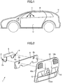
- FIG. 1 is a sectional view of a vehicle employing a burglar sensor arrangement structure according to a first embodiment of the present invention.
- a burglar sensor in the burglar sensor arrangement structure is arranged within a roof center console 1 mounted to an inner surface of a vehicle interior (passenger compartment) C of the vehicle V. More specifically, the roof center console 1 is mounted to a front end region of a ceiling surface R (roof) of the vehicle interior C of the vehicle V at a vehicle width-directional approximately center thereof.
- the burglar sensor comprises a transmitting unit for radiating an ultrasonic wave, and a receiving unit for receiving a reflected wave of the radiated ultrasonic wave.
- the burglar sensor is configured to detect whether or not there is a moving object within the vehicle interior C, based on a Doppler effect arising in the ultrasonic wave received by the receiving unit, thereby detecting an unauthorized intruder.
- FIG. 2 is an exploded perspective view of the roof center console in the first embodiment.
- the roof center console 1 comprises: an ultrasonic wave oscillator 2 which is an ultrasonic wave generation unit; an ultrasonic wave receiver 4 which is an ultrasonic wave receiving unit; a control unit 6 for controlling the ultrasonic wave oscillator 2 and the ultrasonic wave receiver 4; a mounting member 8 for holding each of the ultrasonic wave oscillator 2 and the ultrasonic wave receiver 4 at a given position; and a console cover 10 which is a vehicle interior member for housing the above components.
- a combination of the ultrasonic wave oscillator 2, the ultrasonic wave receiver 4 and the control unit 6 each built in the roof center console 1 makes up the burglar sensor.
- the ultrasonic wave oscillator 2 comprises an approximately circular cylindrical-shaped casing 2a, and is configured to vibrate a built-in vibrator 16 ( FIG. 4 ), based on a driving signal from the control unit 6, to generate an ultrasonic wave having a given frequency.
- the ultrasonic wave oscillator 2 is configured to generate an ultrasonic wave having a frequency of about 40 kHz and a wavelength of about 8.5 mm.
- the ultrasonic wave receiver 4 comprises an approximately circular cylindrical-shaped casing 4a, and is configured to receive an ultrasonic wave generated by the ultrasonic wave oscillator 2 and reflected in the vehicle interior C of the vehicle V.
- the ultrasonic wave receiver 4 is configured to generate an electric signal in response to receiving of the reflected wave, and send the electric signal to the control unit 6.
- each of the ultrasonic wave receiver 4 and the ultrasonic wave oscillator 2 has substantially the same configuration.
- the control unit 6 is connected to the ultrasonic wave oscillator 2 and the ultrasonic wave receiver 4, and configured to control them. Specifically, the control unit 6 is operable, during operation of the burglar sensor, to send the driving signal to the ultrasonic wave oscillator 2 at given time intervals to cause the ultrasonic wave oscillator 2 to generate an ultrasonic wave. Then, the ultrasonic wave receiver 4 is operable, in response to receiving of a reflected wave of the ultrasonic wave generated by the ultrasonic wave oscillator 2, to generate an electric signal, and send the electric signal to the control unit 6. Then, the control unit 6 is operable, based on the electric signal input from the ultrasonic wave receiver 4, to analyze whether or not a Doppler effect arises in the reflected wave, thereby determining the presence or absence of an authorized intruder.
- a Doppler effect arises in an ultrasonic wave reflected from a moving object within the vehicle interior C.
- the control unit 6 is operable to activate a sound generator (not shown) to generate warning sound at a large volume to issue a notice of abnormality.
- control unit 6 may be composed of a microprocessor, a memory, an interface circuit, a program for operating them, a speaker serving as a sound generator for generating warning sound, etc., (these components are not shown).
- the mounting member 8 is a plate-shaped member which is arranged on a vehicle exterior side of the console cover 10 and configured to allow the ultrasonic wave oscillator 2, the ultrasonic wave receiver 4 and the control unit 6 to be fixed at respective appropriate positions therein.
- the mounting member 8 has a holding portion (not shown) provided in a central region of a reverse (vehicle exterior-side) surface thereof (a surface thereof on a side opposite to the console cover 10), and two holding holes 8a, 8b each for holding a respective one of the ultrasonic wave oscillator 2 and the ultrasonic wave receiver 4.
- the holding holes 8a, 8b allow the ultrasonic wave oscillator 2 and the ultrasonic wave receiver 4 to be held at respective appropriate positions on the reverse side (vehicle exterior side) of the console cover 10.
- the console cover 10 is a member forming an external appearance of the center console 1.
- the mounting member 8 is mounted on the side of a reverse (vehicle exterior-side) surface of the console cover 10.
- An ultrasonic wave generated from the ultrasonic wave oscillator 2 is radiated into the vehicle interior C through a sonic emitting portion 10a of the console cover 10, and a reflected ultrasonic wave is received by the ultrasonic wave receiver 4 through a sonic receiving portion 10b of the console cover 10.
- the console cover 10 is further provided with a pair of illumination lamps 12, and a plurality of manipulation switches 14 for manipulating the roof center console 1.
- FIG. 3 is a front view enlargedly showing a portion of the roof center console 1 in which the ultrasonic wave oscillator 2 is built.
- FIG. 4 is an enlarged sectional view taken along the line IV-IV in FIG. 3 .
- FIG. 5 is a diagram showing a sound pressure distribution of an ultrasonic wave generated from the ultrasonic wave oscillator 2, in the vehicle employing the burglar sensor arrangement structure according to the first embodiment.
- the sonic emitting portion 10a is provided on an obverse (vehicle interior-side) surface of the console cover 10 of the center console 1, and a large number of elongate grooves 20 extending parallel to each other are formed on an obverse surface of the sonic emitting portion 10a.
- the ultrasonic wave oscillator 2 of the burglar sensor is arranged on the reverse surface of the console cover 10 in a region corresponding to the sonic emitting portion 10a formed with the grooves.
- the structure of the sonic receiving portion 10b provided on the obverse surface of the console cover 10 is the same as that of the sonic emitting portion 10a.
- the after-mentioned arrangement structure of the ultrasonic wave oscillator 2 with respect to the console cover 10 is the same as that of the ultrasonic wave receiver 4 with respect to the console cover 10.
- the casing 2a of the ultrasonic wave oscillator 2 is fitted in the holding hole 8a provided in the mounting member 8 and held at an appropriate position of the reverse surface of the console cover 10.
- an ultrasonic vibrator 16 (vibration plate) is arranged within the casing 2a of the ultrasonic wave oscillator 2, and configured to be oscillated at a high frequency in response to the driving signal applied thereto.
- an obverse-side opening of the casing 2a of the ultrasonic wave oscillator 2 is covered by the reverse surface of the console cover 10, and a chamber 22 is formed between the ultrasonic vibrator 16 and the reverse surface of the console cover 10.
- a portion of the console cover 10 covering the ultrasonic wave oscillator 2 is provided with two elongate holes extending parallel to each other.
- Each of the two elongate holes functions as a throat portion 18 associated with the ultrasonic wave oscillator 2.
- each of the elongate holes forming the throat portions 18 is formed in an oval cross-sectional shape having a width of about 1 mm and a length of about 3.5 mm which are less than the diameter of the ultrasonic vibrator 16.
- an outside opening 18a at a distal end of each of the throat portions 18 is located within one of the grooves 20 formed on the obverse surface of the console cover 10. That is, respective outside openings of the two throat portions 18 are opened at a bottom surface of one of the grooves 20.
- the length T of the throat portion 18 is determined by a wall thickness of the portion of the console cover 10 formed with the elongate holes. In this embodiment, the length T is about 1 mm.
- each of the grooves 20 is formed with a rectangular cross-section having a depth D of about 1 mm and a width W of about 3 mm, wherein the large number of grooves 20 each having such a cross-sectional shape are formed to extend parallel to each other at even intervals of about 1 mm.
- the outside openings 18a of the two throat portions 18 are opened to an endmost one of the grooves 20 in the sonic emitting portion 10a, such that they are arranged side-by-side in a width direction of the endmost groove 20 to extend parallel to a length direction of the endmost groove 20.
- each of the outside openings 18a is formed in a region of the endmost groove 20 away from one end of the endmost groove 20 by a distance L of about 10 mm ( FIG. 3 ).
- each of the outside openings 18a of the throat portions 18 is formed in a region of a specific one of the grooves 20 away from opposite ends of the specific groove 20 by a distance L which is greater than a wavelength of an ultrasonic wave to be radiated (in this embodiment, about 8.5 mm).
- each of the grooves 20 is preferably formed to have a width W which is equal to or less than a wavelength of an ultrasonic wave to be radiated, a length which is equal to or greater than two times the wavelength of the ultrasonic wave to be radiated, and a depth of about 1 mm or more. In this case, it is possible to sufficiently control directivity of a radiated ultrasonic wave.
- the ultrasonic vibrator 16 When the driving signal is sent from the control unit 6 to the ultrasonic wave oscillator 2, the ultrasonic vibrator 16 is oscillated at a high frequency to generate an ultrasonic wave in the chamber 22.
- the ultrasonic wave generated in the chamber 22 is radiated from the side of the obverse surface of the console cover 10 via the two throat portions 18 formed in the console cover 10.
- the outside openings 18a of the throat portions 18 are opened at the bottom surface of the endmost groove 20, so that an inner wall surface of the endmost groove 20 acts like an acoustic horn, so that the directivity of the radiated ultrasonic wave is improved.
- FIG. 5 shows a sound pressure distribution of an ultrasonic wave generated from the ultrasonic wave oscillator 2, specifically, a sound pressure distribution in a case where an ultrasonic wave is generated from the ultrasonic wave oscillator 2 arranged in the arrangement structure illustrated in FIGS. 3 and 4.
- FIG. 5 shows that an ultrasonic wave radiated from the outside openings 18a of the two throat portions 18 as a sonic emitting source S to the outside spreads around a space, and a sound pressure is gradually lowered with distance from the sonic emitting source S.
- the ultrasonic wave from the outside openings 18a is radiated from the bottom surface of the groove 20, instead of being radiated directly, so that directivity is improved such that the ultrasonic wave spreads at a sufficiently wide angle.
- the arrangement structure of the burglar sensor (ultrasonic wave oscillator 2) is contrived such that the outside openings 18a are provided to the bottom surface of the endmost groove 20, thereby improving a sound pressure distribution or directivity.
- FIG. 6 is a perspective view showing an external appearance of an ultrasonic wave oscillator in the comparative example
- FIG. 7 is a diagram showing a sound pressure distribution of an ultrasonic wave generated from the ultrasonic wave oscillator in the comparative example.
- the ultrasonic wave oscillator 24 of the comparative example comprises an approximately circular cylindrical-shaped casing 24a, and an ultrasonic vibrator (not shown) built in the casing 24a and configured to be oscillated at a high frequency.
- a cover 24b is provided at one end of the casing 24a to cover the ultrasonic vibrator, and two throat portions 26 each having an oval cross-section are formed to protrude from the cover 24b and arranged side-by-side to extend parallel to each other.
- each of the throat portions 18 is formed by an elongate hole provided in the console cover 10, whereas, in the ultrasonic wave oscillator 24 in the comparative example, each of the throat portions 26 is formed inside a protruding tubular wall surface.
- Each of the throat portions 26 is formed in an oval cross-sectional shape having a width of about 1 mm and a length of about 3.5 mm, as with each of the throat portions 18 associated with the ultrasonic wave oscillator 2 in the first embodiment.
- the ultrasonic wave oscillator 24 in the comparative example an ultrasonic wave generated by vibration of the ultrasonic vibrator built in the casing 24a is radiated to a chamber in the casing 24a once, and the ultrasonic wave in the chamber is radiated from respective outside openings 26a of the two throat portions 18 to the outside via the throat portions 18. That is, the ultrasonic wave oscillator 24 in the comparative example is acoustically equivalent to the ultrasonic wave oscillator 2 in the first embodiment, except that the outside openings are opened at the bottom surface of one of the grooves.
- FIG. 7 shows a sound pressure distribution of an ultrasonic wave radiated from the ultrasonic wave oscillator 24 in the comparative example.
- an ultrasonic wave passing through the throat portions 26 is directly radiated from the outside openings 26a to a free space.
- an ultrasonic wave generated by the ultrasonic vibrator is not radiated directly but radiated via the two throat portions 26, so that directivity is controlled to allow the ultrasonic wave to spread at a sufficiently wide angle.
- the sound pressure distribution in the comparative example illustrated in FIG. 5 in the sound pressure distribution in the comparative example illustrated in FIG.
- the outside openings 18a of the throat portions 18 are opened at the bottom surface of the groove 20, so that it is possible to obtain a horn effect and thus radiate the ultrasonic wave at a high sound pressure and over a wide range in the vehicle interior C.
- the configuration of the sonic receiving portion 10b provided in the console cover 10 is the same as that of the sonic emitting portion 10a, and the arrangement structure of the ultrasonic wave receiver 4 with respect to the console cover 10 is also the same as that of the ultrasonic wave oscillator 2. Further, it is know that the reciprocity theorem is applicable to an acoustic system. As is evident from the above, by employing, in the ultrasonic wave receiver 4, the same arrangement structure as that of the ultrasonic wave oscillator 2, it becomes possible to receive an ultrasonic wave at a high sensitivity over a wide range in the vehicle interior C.
- each of the throat portions 19 is formed by the elongate hole provided in the console cover 10, separately from the ultrasonic wave oscillator 2.
- the burglar sensor arrangement structure of the present invention may be constructed using the ultrasonic wave oscillator 24 integrally formed with the throat portions 19 as in the comparative example.
- the ultrasonic wave oscillator 24 may be arranged such that the outside openings 26a of the throat portions 26 are located to become flush with the bottom surface of a specific one of the grooves 20 so as to open the outside openings 26a at the bottom surface of the specific groove 20.
- This configuration also makes it possible to obtain the hone effect based on the groove 20, and thus obtain the same sound pressure distribution as that illustrated in FIG. 5 .
- the outside opening 18a of the throat portion 18 is opened at the bottom surface of the groove 20, so that the ultrasonic wave radiated from the outside opening 18a is emitted into the vehicle interior C while undergoing reflection at an inner wall surface of the groove 20.
- the inner wall surface of the groove 20 acts like an acoustic horn, which makes it possible to enhance ultrasonic wave propagation capability, and control directivity of the ultrasonic wave radiated into the vehicle interior C via the groove 20.
- the outside opening 18a of the throat portion 18 associated with the ultrasonic wave oscillator 2 is opened to the console cover 10, so that the ultrasonic wave oscillator 2 and the console cover 10 are in close contact with each other, and thereby it is possible to install the burglar sensor inside the roof center console 1 in a compact manner.
- the outside openings 18a of the two throat portions 18 are opened at the bottom surface of the same groove 20, so that it is possible to further enhance the ultrasonic wave propagation capability.
- the burglar sensor is arranged with respect to (the console cover of) the roof center console 1, which is the vehicle interior member, so that it is possible to radiate an ultrasonic wave from a vehicle width-directional approximately center of the ceiling surface R of the vehicle interior C to allow the ultrasonic wave to be easily spread throughout the vehicle interior C.
- FIG. 8 is a perspective view of an ultrasonic wave oscillator employed in the second embodiment to serve as an ultrasonic wave generation unit.
- FIG. 9 is a diagram showing a sound pressure distribution obtained in a case where the ultrasonic wave oscillator illustrated in FIG. 8 is operated in a stand-alone manner.
- the burglar sensor arrangement structure according to the second embodiment is different from the first embodiment, in terms of the structure of an ultrasonic wave oscillator to be used. Thus, the following description will be made about only a difference between the first embodiment and the second embodiment, and description of the common configuration and functions/effects therebetween will be omitted.
- an ultrasonic wave oscillator 30 employed in the second embodiment comprises an approximately circular cylindrical-shaped casing 30a, and an ultrasonic vibrator (not shown) built in the casing 30a and configured to be oscillated at a high frequency. Further, the ultrasonic vibrator in the casing 30a is covered by a cover 30b, and a single tubular throat portion 32 is formed to protrude from the center of the cover 30b. A passage formed inside the throat portion 32 spreads in a conical shape toward an outside opening 32a of the throat portion 32.
- an ultrasonic wave generated by vibration of an ultrasonic vibrator built in the casing 30a is radiated to a chamber in the casing 30a once, and the ultrasonic wave in the chamber is radiated from the outside opening 32a to the outside via the throat portion 32.
- FIG. 9 shows a sound pressure distribution of an ultrasonic wave obtained in a case where the ultrasonic wave oscillator 30 is operated in a stand-alone manner.
- the ultrasonic wave generated by the ultrasonic vibrator (vibration plate) passes through the throat portion 32 having a cross-section less than that of the vibration plate, and therefore receives resistance.
- a sound pressure distribution has a rounded shape.
- an ultrasonic wave generated by the ultrasonic vibrator is not radiated directly but radiated via the throat portion 32, so that directivity is controlled to allow the ultrasonic wave to spread at a sufficiently wide angle.
- spreading of the ultrasonic wave is insufficient, and a range capable of obtaining a sufficiently high sound pressure is narrow.
- the ultrasonic wave oscillator 30 in the second embodiment is incapable of obtaining a sufficiently wide directivity when it is operated in a stand-alone manner
- the ultrasonic wave oscillator 30 can have a sufficiently wide directivity by arranging it in the same manner as that in the arrangement structure according to the first embodiment. Specifically, by arranging the outside opening 32a of the throat portion 32 such that it is opened at a bottom surface of a groove formed on a vehicle interior member, in the same manner as that in the first embodiment, it becomes possible to obtain a wide directivity equivalent to the pressure distribution illustrated in FIG. 5 .
- an ultrasonic wave oscillator having a throat portion with any of various cross-sectional shapes can be applied to the burglar sensor arrangement structure of the present invention.
- the throat portion 32 is integrally provided to the ultrasonic wave oscillator 30.
- the throat portion 32 may be formed by a conical hole provided in a vehicle interior member (console cover).
- FIG. 10 is a sectional view of a state in which an ultrasonic wave oscillator is mounted to a vehicle interior member, in the burglar sensor arrangement structure according to the third embodiment.
- FIG. 11 is a diagram showing a sound pressure distribution of an ultrasonic wave radiated from the arrangement structure illustrated in FIG. 10 .
- the burglar sensor arrangement structure according to the third embodiment is different from the first embodiment, in terms of the structure of an ultrasonic wave oscillator to be used, and the structure of a vehicle interior member to which the ultrasonic wave oscillator is mounted.
- the following description will be made about only a difference between the first embodiment and the third embodiment, and description of the common configuration and functions/effects therebetween will be omitted.
- an ultrasonic wave oscillator 42 which is an ultrasonic wave generation unit is mounted to a reverse surface of a vehicle interior member 40.
- An obverse surface of the vehicle interior member 40 is formed with a large number of linear grooves 40a extending parallel to each other at even intervals.
- Each of the grooves 40a is formed with an approximately square cross-section having a width of about 1 mm and a depth of about 1 mm. Further, the grooves 40a are formed at intervals of about 1 mm.
- a groove 40b provided on the obverse surface of the vehicle interior member 40 in a region corresponding to the ultrasonic wave oscillator 42 is formed with an approximately rectangular cross-section having a relatively wide width of about 3 mm and a depth of about 1 mm, wherein two or more of the grooves 40a each having a relatively narrow width are formed on each side of the wide groove 40b.
- the ultrasonic wave oscillator 42 comprises an approximately circular cylindrical-shaped casing 42a, and an ultrasonic vibrator 44 built in the casing 42a and configured to be oscillated at a high frequency. Further, the ultrasonic vibrator 44 in the casing 42a is covered by a cover 42b, and two cross-sectionally oval and tubular throat portions 46 are formed to protrude from the cover 42b. Respective outside openings 46a of the two throat portions 46 are opened at a bottom surface of the single wide groove 40b and located to become flush with the bottom surface of the groove 40b.
- the configuration of a passage formed inside each of the throat portions 46 is the same as that of the throat portions associated with the ultrasonic wave oscillator 24 illustrated in FIG. 6 .
- an ultrasonic wave generated by vibration of the ultrasonic vibrator 44 built in the casing 42a is radiated to a chamber in the casing 42a once, and the ultrasonic wave in the chamber is radiated from the outside openings 46a to the outside via the throat portions 46.
- FIG. 11 shows a sound pressure distribution of an ultrasonic wave radiated in the arrangement structure illustrated in FIG. 10 .
- the groove 40a is formed on each side of the groove 40b to which the outside opening 46a of the throat portion 46 is opened, so that the ultrasonic wave radiated from the groove 40b is hit against and reflected by wall surfaces of the grooves 40a formed on both sides of the groove 40b.
- two or more of the grooves 40a are formed on the vehicle interior member at positions on each side of the groove 40b, so that it is possible to cause interference with reflected waves from the larger number of grooves 40a. This makes it possible to give a wider variety of directivities to the ultraviolet wave to be radiated, and further improve the ultrasonic wave propagation capability.
- FIG. 12 is a sectional view of a state in which an ultrasonic wave oscillator is mounted to a vehicle interior member, in the burglar sensor arrangement structure according to the fourth embodiment.
- FIG. 13 is a diagram showing a sound pressure distribution of an ultrasonic wave radiated from the arrangement structure illustrated in FIG. 12 .
- the burglar sensor arrangement structure according to the fourth embodiment is different from the first embodiment, in terms of the structure of an ultrasonic wave oscillator to be used, and the structure of a vehicle interior member to which the ultrasonic wave oscillator is mounted.
- the following description will be made about only a difference between the first embodiment and the fourth embodiment, and description of the common configuration and functions/effects therebetween will be omitted.
- an ultrasonic wave oscillator 52 which is an ultrasonic wave generation unit is mounted to a reverse surface of a vehicle interior member 50.
- An obverse surface of the vehicle interior member 50 is formed with a large number of linear grooves 50a extending parallel to each other at even intervals.
- Each of the grooves 50a is formed with an approximately rectangular cross-section having a width of about 3 mm and a depth of about 1 mm. Further, the grooves 50a are formed at intervals of about 3 mm.
- a groove 50b provided on the obverse surface of the vehicle interior member 50 in a region corresponding to the ultrasonic wave oscillator 52 is formed with an approximately rectangular cross-section having a width of about 3 mm and a depth of about 1 mm, as with the other grooves 50a, wherein two or more of the grooves 50a are formed on each side of the groove 50b.
- the ultrasonic wave oscillator 52 comprises an approximately circular cylindrical-shaped casing 52a, and an ultrasonic vibrator 54 built in the casing 52a and configured to be oscillated at a high frequency. Further, the ultrasonic vibrator 54 in the casing 52a is covered by a cover 52b, and two cross-sectionally oval and tubular throat portions 56 are formed to protrude from the cover 52b. Respective outside openings 56a of the two throat portions 56 are opened at a bottom surface of the single groove 50b and located to become flush with the bottom surface of the groove 50b.
- the configuration of a passage formed inside each of the throat portions 56 is the same as that of the throat portions associated with the ultrasonic wave oscillator 24 illustrated in FIG. 6 .
- an ultrasonic wave generated by vibration of the ultrasonic vibrator 54 built in the casing 52a is radiated to a chamber in the casing 52a once, and the ultrasonic wave in the chamber is radiated from the outside openings 56a to the outside via the throat portions 56.
- FIG. 13 shows a sound pressure distribution of an ultrasonic wave radiated in the arrangement structure illustrated in FIG. 12 .
- the radiated ultrasonic wave has a significantly narrow directivity, although the configuration of the throat portions is substantially the same as that in the first embodiment.
- the directivity in the sound distribution in the fourth embodiment is narrower than that in the sound distribution illustrated in FIG. 5 , and narrower than that in the sound distribution illustrated in FIG. 7 , obtained in the case where an ultrasonic wave is radiated from the ultrasonic wave oscillator 24 in a stand-alone manner. It is believed that this sound pressure distribution is formed as a result of superimposition of reflected waves from the large number of grooves 50a formed on both sides of the groove 50b to which the outside opening 56a of the throat portion 56 is opened.
- the burglar sensor arrangement structure providing such a narrow directivity is unsuited for applications necessary to spread an ultrasonic wave radiated from one ultrasonic wave oscillator throughout a vehicle interior C, but suitable as a burglar sensor arrangement structure intended to detect intrusion into a specific region of a vehicle interior C with absolute accuracy.
- an ultrasonic wave radiated from the ultrasonic wave oscillator 52 in the arrangement structure according to the fourth embodiment is significant stable in terms of sound pressure distribution, and increased in terms of sound pressure.
- the burglar sensor is arranged on the vehicle exterior side of the console cover.
- the arrangement structure of the present invention may be applied to a case where the burglar sensor is arranged with respect to any suitable vehicle interior member other than the console cover, such as an instrument panel.
- the bottom surface of the groove to which the outside opening of the throat portion is opened is a flat surface
- the bottom surface of this groove may be formed in a curved surface.
Landscapes
- Engineering & Computer Science (AREA)
- Physics & Mathematics (AREA)
- General Physics & Mathematics (AREA)
- Radar, Positioning & Navigation (AREA)
- Remote Sensing (AREA)
- Mechanical Engineering (AREA)
- Computer Networks & Wireless Communication (AREA)
- Acoustics & Sound (AREA)
- Multimedia (AREA)
- Burglar Alarm Systems (AREA)
- Emergency Alarm Devices (AREA)
- Measurement Of Velocity Or Position Using Acoustic Or Ultrasonic Waves (AREA)
- Transducers For Ultrasonic Waves (AREA)
Abstract
Description
- The present invention relates to a burglar sensor arrangement structure, and more particularly to a burglar sensor arrangement structure for arranging, with respect to a vehicle interior member, a burglar sensor configured to detect an intrusion into a vehicle interior.
- A vehicle intrusion detection device is described in
JP 2013-221902A - Patent Document 1:
JP 2013-221902A - In the invention described in the
Parent Document 1, with a view to forming a side lobe having a desired direction, in an ultrasonic wave generated by the ultrasonic wave transmitting means, the ultrasonic wave transmitting means is covered by the cover member, such that the ultrasonic wave is radiated through the opening of the cover member. However, in order to allow the ultrasonic wave radiated from the ultrasonic wave transmitting means to be reflected by the fins provided in the opening of the cover member, thereby obtaining a desired side lobe, the ultrasonic wave transmitting means and the cover member need to be spaced apart from each other to some extent. Thus, in a case where it is attempted to install the vehicle intrusion detection device (burglar sensor) described in the ParentDocument 1, on a vehicle exterior side of a vehicle interior member arranged in a vehicle interior (passenger compartment) of a vehicle, a large space is required for the installation. However, there is a problem that it is difficult to ensure such a large installation space. - It is therefore an object of the present invention to provide a burglar sensor arrangement structure capable of installing a burglar sensor with respect to a vehicle interior member in a compact manner, while giving a desired directivity to a radiated ultrasonic wave.
- In order to solve the above problem, the present invention provides a burglar sensor arrangement structure for arranging, with respect to a vehicle interior member, a burglar sensor configured to detect an intrusion into a vehicle interior. The burglar sensor arrangement structure comprises: an ultrasonic wave generation unit for generating an ultrasonic wave; and a throat portion for radiating the ultrasonic wave generated in the ultrasonic wave generation unit, from an outside opening thereof into the vehicle interior, wherein the vehicle interior member is formed with a groove, and the outside opening of the throat portion is opened at a bottom surface of the groove.
- In the burglar sensor arrangement structure of the present invention having the above feature, when the ultrasonic wave generation unit generates an ultrasonic wave, the generated ultrasonic wave is guided through the throat portion and radiated from the outside opening of the throat portion. The outside opening of the throat portion is opened at the bottom surface of the groove formed on the vehicle interior member. Thus, the ultrasonic wave radiated from the outside opening is radiated from the groove into the vehicle interior.
- More specifically, in the above burglar sensor arrangement structure of the present invention, the outside opening of the throat portion is opened at the bottom surface of the groove, so that the ultrasonic wave radiated from the outside opening is emitted into the vehicle interior while undergoing reflection at an inner wall surface of the groove. As a result, the inner wall surface of the groove acts like an acoustic horn, which makes it possible to enhance ultrasonic wave propagation capability, and control directivity of the ultrasonic wave radiated into the vehicle interior via the groove. Further, the outside opening of the throat portion associated with the ultrasonic wave generation unit is opened to the vehicle interior member, so that there is no need to arrange the ultrasonic wave generation unit and the vehicle interior member such that they are largely spaced apart from each other, and thereby it is possible to install the burglar sensor with respect to the vehicle interior member in a compact manner. Further, the groove provided on the vehicle interior member in which the burglar sensor is arranged can be easily fit in ornaments to be given to the vehicle interior member, so that it is possible to arrange the burglar sensor with respect to the vehicle interior member substantially without spoiling aesthetic quality of a vehicle interior.
- Preferably, in the burglar sensor arrangement structure of the present invention, the throat portion is provided by a number of two per said ultrasonic wave generation unit, wherein respective outside openings of the two throat portions are opened at the bottom surface of the same groove.
- According to this feature, the outside openings of the two throat portions are opened at the bottom surface of the same groove, so that it is possible to further enhance the ultrasonic wave propagation capability. Further, the arrangement of the two outside openings may be appropriately set. In this case, it becomes possible to more easily control the directivity of a radiated ultrasonic wave.
- Preferably, in the burglar sensor arrangement structure of the present invention, the vehicle interior member is a console cover of a roof center console mounted to a ceiling surface of the vehicle interior.
- According to this feature, the burglar sensor is arranged with respect to the console cover of the roof center console, which is the vehicle interior member, so that it is possible to radiate an ultrasonic wave from a vehicle width-directional approximately center of the ceiling surface of the vehicle interior to allow the ultrasonic wave to be easily spread throughout the vehicle interior.
- Preferably, in the burglar sensor arrangement structure of the present invention, the vehicle interior member is formed with at least three grooves, wherein at least one of the grooves is formed on each sides of the groove to which the outside opening of the throat portion is opened.
- According to this feature, at least one of the grooves is additionally formed on each sides of the central groove to which the outside opening of the throat portion is opened, so that the ultrasonic wave radiated from the central groove is hit against and reflected by wall surfaces of the side grooves formed on both sides of the central groove. By causing interference between a reflected wave from the wall surface of each of the side grooves and the ultrasonic wave directly radiated from the central groove to which the outside opening of the throat portion is opened, it becomes possible to form a desired directivity characteristic, and further improve the ultrasonic wave propagation capability.
- More preferably, in the above burglar sensor arrangement structure, the vehicle interior member is formed with at least five grooves, wherein the groove to which the outside opening of the throat portion is opened has a width greater than that of each of the remaining grooves.
- According to this feature, the five or more grooves are formed on the vehicle interior member, so that it is possible to cause interference with reflected waves from a larger number of side grooves. This makes it possible to give a wider variety of directivities to the ultrasonic wave to be radiated, and further improve the ultrasonic wave propagation capability.
- The burglar sensor arrangement structure makes it possible to install the burglar sensor with respect to the vehicle interior member in a compact manner, while giving a desired directivity to a radiated ultrasonic wave.
-
-
FIG. 1 is a sectional view of a vehicle employing a burglar sensor arrangement structure according to a first embodiment of the present invention. -
FIG. 2 is an exploded perspective view of a roof center console employing the burglar sensor arrangement structure according to the first embodiment. -
FIG. 3 is a front view enlargedly showing a portion of the roof center console in which an ultrasonic wave oscillator is built, in the burglar sensor arrangement structure according to the first embodiment. -
FIG. 4 is an enlarged sectional view of the roof center console in the burglar sensor arrangement structure according to the first embodiment, taken along the line IV-IV inFIG. 3 . -
FIG. 5 is a diagram showing a sound pressure distribution of an ultrasonic wave generated from the ultrasonic wave oscillator, in the burglar sensor arrangement structure according to the first embodiment. -
FIG. 6 is a perspective view showing an external appearance of an ultrasonic wave oscillator in a comparative example with respect to embodiments of the present invention. -
FIG. 7 is a diagram showing a sound pressure distribution of an ultrasonic wave generated from the ultrasonic wave oscillator in the comparative example with respect to embodiments of the present invention. -
FIG. 8 is a perspective view of an ultrasonic wave oscillator employed in a burglar sensor arrangement structure according to a second embodiment of the present invention. -
FIG. 9 is a diagram showing a sound pressure distribution obtained in a case where the ultrasonic wave oscillator illustrated inFIG. 8 is operated in a stand-alone manner, in the burglar sensor arrangement structure according to the second embodiment. -
FIG. 10 is a sectional view of a state in which an ultrasonic wave oscillator is mounted to a vehicle interior member, in a burglar sensor arrangement structure according to a third embodiment of the present invention. -
FIG. 11 is a diagram showing a sound pressure distribution of an ultrasonic wave radiated from the burglar sensor arrangement structure according to the third embodiment illustrated inFIG. 10 . -
FIG. 12 is a sectional view of a state in which an ultrasonic wave oscillator is mounted to a vehicle interior member, in a burglar sensor arrangement structure according to a fourth embodiment of the present invention. -
FIG. 13 is a diagram showing a sound pressure distribution of an ultrasonic wave radiated from the burglar sensor arrangement structure according to the fourth embodiment illustrated inFIG. 12 . - With reference to the accompanying drawings, preferred embodiments of the present invention will now be described.
-
FIG. 1 is a sectional view of a vehicle employing a burglar sensor arrangement structure according to a first embodiment of the present invention. - As shown in
FIG. 1 , a burglar sensor in the burglar sensor arrangement structure according to the first embodiment is arranged within aroof center console 1 mounted to an inner surface of a vehicle interior (passenger compartment) C of the vehicle V. More specifically, theroof center console 1 is mounted to a front end region of a ceiling surface R (roof) of the vehicle interior C of the vehicle V at a vehicle width-directional approximately center thereof. The burglar sensor comprises a transmitting unit for radiating an ultrasonic wave, and a receiving unit for receiving a reflected wave of the radiated ultrasonic wave. The burglar sensor is configured to detect whether or not there is a moving object within the vehicle interior C, based on a Doppler effect arising in the ultrasonic wave received by the receiving unit, thereby detecting an unauthorized intruder. -
FIG. 2 is an exploded perspective view of the roof center console in the first embodiment. - As shown in
FIG. 2 , theroof center console 1 comprises: anultrasonic wave oscillator 2 which is an ultrasonic wave generation unit; anultrasonic wave receiver 4 which is an ultrasonic wave receiving unit; acontrol unit 6 for controlling theultrasonic wave oscillator 2 and theultrasonic wave receiver 4; amounting member 8 for holding each of theultrasonic wave oscillator 2 and theultrasonic wave receiver 4 at a given position; and aconsole cover 10 which is a vehicle interior member for housing the above components. In this embodiment, a combination of theultrasonic wave oscillator 2, theultrasonic wave receiver 4 and thecontrol unit 6 each built in theroof center console 1 makes up the burglar sensor. - The
ultrasonic wave oscillator 2 comprises an approximately circular cylindrical-shaped casing 2a, and is configured to vibrate a built-in vibrator 16 (FIG. 4 ), based on a driving signal from thecontrol unit 6, to generate an ultrasonic wave having a given frequency. Specifically, in this embodiment, theultrasonic wave oscillator 2 is configured to generate an ultrasonic wave having a frequency of about 40 kHz and a wavelength of about 8.5 mm. - The
ultrasonic wave receiver 4 comprises an approximately circular cylindrical-shapedcasing 4a, and is configured to receive an ultrasonic wave generated by theultrasonic wave oscillator 2 and reflected in the vehicle interior C of the vehicle V. Theultrasonic wave receiver 4 is configured to generate an electric signal in response to receiving of the reflected wave, and send the electric signal to thecontrol unit 6. In this embodiment, each of theultrasonic wave receiver 4 and theultrasonic wave oscillator 2 has substantially the same configuration. - The
control unit 6 is connected to theultrasonic wave oscillator 2 and theultrasonic wave receiver 4, and configured to control them. Specifically, thecontrol unit 6 is operable, during operation of the burglar sensor, to send the driving signal to theultrasonic wave oscillator 2 at given time intervals to cause theultrasonic wave oscillator 2 to generate an ultrasonic wave. Then, theultrasonic wave receiver 4 is operable, in response to receiving of a reflected wave of the ultrasonic wave generated by theultrasonic wave oscillator 2, to generate an electric signal, and send the electric signal to thecontrol unit 6. Then, thecontrol unit 6 is operable, based on the electric signal input from theultrasonic wave receiver 4, to analyze whether or not a Doppler effect arises in the reflected wave, thereby determining the presence or absence of an authorized intruder. - Specifically, a Doppler effect arises in an ultrasonic wave reflected from a moving object within the vehicle interior C. Thus, when a Doppler effect is detected in a state in which there is no authorized passenger within the vehicle interior C, it can be determined that there is an unauthorized intruder within the vehicle interior C. Upon detection of an unauthorized intruder, the
control unit 6 is operable to activate a sound generator (not shown) to generate warning sound at a large volume to issue a notice of abnormality. - Specifically, the
control unit 6 may be composed of a microprocessor, a memory, an interface circuit, a program for operating them, a speaker serving as a sound generator for generating warning sound, etc., (these components are not shown). - The mounting
member 8 is a plate-shaped member which is arranged on a vehicle exterior side of theconsole cover 10 and configured to allow theultrasonic wave oscillator 2, theultrasonic wave receiver 4 and thecontrol unit 6 to be fixed at respective appropriate positions therein. Specifically, the mountingmember 8 has a holding portion (not shown) provided in a central region of a reverse (vehicle exterior-side) surface thereof (a surface thereof on a side opposite to the console cover 10), and two holdingholes ultrasonic wave oscillator 2 and theultrasonic wave receiver 4. The holdingholes ultrasonic wave oscillator 2 and theultrasonic wave receiver 4 to be held at respective appropriate positions on the reverse side (vehicle exterior side) of theconsole cover 10. - The
console cover 10 is a member forming an external appearance of thecenter console 1. The mountingmember 8 is mounted on the side of a reverse (vehicle exterior-side) surface of theconsole cover 10. An ultrasonic wave generated from theultrasonic wave oscillator 2 is radiated into the vehicle interior C through a sonic emittingportion 10a of theconsole cover 10, and a reflected ultrasonic wave is received by theultrasonic wave receiver 4 through asonic receiving portion 10b of theconsole cover 10. Theconsole cover 10 is further provided with a pair ofillumination lamps 12, and a plurality of manipulation switches 14 for manipulating theroof center console 1. - Next, with reference to
FIGS. 3 to 5 , the burglar sensor arrangement structure according to the first embodiment will be described.FIG. 3 is a front view enlargedly showing a portion of theroof center console 1 in which theultrasonic wave oscillator 2 is built.FIG. 4 is an enlarged sectional view taken along the line IV-IV inFIG. 3 .FIG. 5 is a diagram showing a sound pressure distribution of an ultrasonic wave generated from theultrasonic wave oscillator 2, in the vehicle employing the burglar sensor arrangement structure according to the first embodiment. - As shown in
FIGS. 3 and4 , the sonic emittingportion 10a is provided on an obverse (vehicle interior-side) surface of theconsole cover 10 of thecenter console 1, and a large number ofelongate grooves 20 extending parallel to each other are formed on an obverse surface of the sonic emittingportion 10a. Theultrasonic wave oscillator 2 of the burglar sensor is arranged on the reverse surface of theconsole cover 10 in a region corresponding to the sonic emittingportion 10a formed with the grooves. In this embodiment, the structure of the sonic receivingportion 10b provided on the obverse surface of theconsole cover 10 is the same as that of the sonic emittingportion 10a. Further, the after-mentioned arrangement structure of theultrasonic wave oscillator 2 with respect to theconsole cover 10 is the same as that of theultrasonic wave receiver 4 with respect to theconsole cover 10. - As shown in
FIG. 4 , thecasing 2a of theultrasonic wave oscillator 2 is fitted in the holdinghole 8a provided in the mountingmember 8 and held at an appropriate position of the reverse surface of theconsole cover 10. Further, an ultrasonic vibrator 16 (vibration plate) is arranged within thecasing 2a of theultrasonic wave oscillator 2, and configured to be oscillated at a high frequency in response to the driving signal applied thereto.
Further, an obverse-side opening of thecasing 2a of theultrasonic wave oscillator 2 is covered by the reverse surface of theconsole cover 10, and achamber 22 is formed between theultrasonic vibrator 16 and the reverse surface of theconsole cover 10. - A portion of the
console cover 10 covering theultrasonic wave oscillator 2 is provided with two elongate holes extending parallel to each other. Each of the two elongate holes functions as athroat portion 18 associated with theultrasonic wave oscillator 2. In this embodiment, each of the elongate holes forming thethroat portions 18 is formed in an oval cross-sectional shape having a width of about 1 mm and a length of about 3.5 mm which are less than the diameter of theultrasonic vibrator 16. Further, anoutside opening 18a at a distal end of each of thethroat portions 18 is located within one of thegrooves 20 formed on the obverse surface of theconsole cover 10. That is, respective outside openings of the twothroat portions 18 are opened at a bottom surface of one of thegrooves 20. Further, the length T of thethroat portion 18 is determined by a wall thickness of the portion of theconsole cover 10 formed with the elongate holes. In this embodiment, the length T is about 1 mm. - In this embodiment, each of the
grooves 20 is formed with a rectangular cross-section having a depth D of about 1 mm and a width W of about 3 mm, wherein the large number ofgrooves 20 each having such a cross-sectional shape are formed to extend parallel to each other at even intervals of about 1 mm. Further, in this embodiment, as shown inFIG. 3 , theoutside openings 18a of the twothroat portions 18 are opened to an endmost one of thegrooves 20 in the sonic emittingportion 10a, such that they are arranged side-by-side in a width direction of theendmost groove 20 to extend parallel to a length direction of theendmost groove 20. Further, each of theoutside openings 18a is formed in a region of theendmost groove 20 away from one end of theendmost groove 20 by a distance L of about 10 mm (FIG. 3 ). Preferably, each of theoutside openings 18a of thethroat portions 18 is formed in a region of a specific one of thegrooves 20 away from opposite ends of thespecific groove 20 by a distance L which is greater than a wavelength of an ultrasonic wave to be radiated (in this embodiment, about 8.5 mm). Further, each of thegrooves 20 is preferably formed to have a width W which is equal to or less than a wavelength of an ultrasonic wave to be radiated, a length which is equal to or greater than two times the wavelength of the ultrasonic wave to be radiated, and a depth of about 1 mm or more. In this case, it is possible to sufficiently control directivity of a radiated ultrasonic wave. - When the driving signal is sent from the
control unit 6 to theultrasonic wave oscillator 2, theultrasonic vibrator 16 is oscillated at a high frequency to generate an ultrasonic wave in thechamber 22. The ultrasonic wave generated in thechamber 22 is radiated from the side of the obverse surface of theconsole cover 10 via the twothroat portions 18 formed in theconsole cover 10. Here, theoutside openings 18a of thethroat portions 18 are opened at the bottom surface of theendmost groove 20, so that an inner wall surface of theendmost groove 20 acts like an acoustic horn, so that the directivity of the radiated ultrasonic wave is improved. -
FIG. 5 shows a sound pressure distribution of an ultrasonic wave generated from theultrasonic wave oscillator 2, specifically, a sound pressure distribution in a case where an ultrasonic wave is generated from theultrasonic wave oscillator 2 arranged in the arrangement structure illustrated inFIGS. 3 and4. FIG. 5 shows that an ultrasonic wave radiated from theoutside openings 18a of the twothroat portions 18 as a sonic emitting source S to the outside spreads around a space, and a sound pressure is gradually lowered with distance from the sonic emitting source S. Here, the ultrasonic wave from theoutside openings 18a is radiated from the bottom surface of thegroove 20, instead of being radiated directly, so that directivity is improved such that the ultrasonic wave spreads at a sufficiently wide angle. In the sound pressure distribution illustrated inFIG. 5 , three regions each having a sufficiently high sound pressure are formed around the sonic emitting source S to spread, respectively, in three different directions, so that it is possible to sufficiently spread the ultrasonic wave throughout the vehicle interior C. In this embodiment, the arrangement structure of the burglar sensor (ultrasonic wave oscillator 2) is contrived such that theoutside openings 18a are provided to the bottom surface of theendmost groove 20, thereby improving a sound pressure distribution or directivity. - Next, as a comparative example, a sound pressure distribution in a case where an ultrasonic wave is radiated directly from the
throat portions 18 associated with theultrasonic wave oscillator 2 will be described with reference toFIGS. 6 and 7. FIG. 6 is a perspective view showing an external appearance of an ultrasonic wave oscillator in the comparative example, andFIG. 7 is a diagram showing a sound pressure distribution of an ultrasonic wave generated from the ultrasonic wave oscillator in the comparative example. - As shown in
FIG. 6 , theultrasonic wave oscillator 24 of the comparative example comprises an approximately circular cylindrical-shapedcasing 24a, and an ultrasonic vibrator (not shown) built in thecasing 24a and configured to be oscillated at a high frequency. Further, acover 24b is provided at one end of thecasing 24a to cover the ultrasonic vibrator, and twothroat portions 26 each having an oval cross-section are formed to protrude from thecover 24b and arranged side-by-side to extend parallel to each other. That is, in theultrasonic wave oscillator 2 in the first embodiment, each of thethroat portions 18 is formed by an elongate hole provided in theconsole cover 10, whereas, in theultrasonic wave oscillator 24 in the comparative example, each of thethroat portions 26 is formed inside a protruding tubular wall surface. Each of thethroat portions 26 is formed in an oval cross-sectional shape having a width of about 1 mm and a length of about 3.5 mm, as with each of thethroat portions 18 associated with theultrasonic wave oscillator 2 in the first embodiment. - As with the first embodiment, in the
ultrasonic wave oscillator 24 in the comparative example, an ultrasonic wave generated by vibration of the ultrasonic vibrator built in thecasing 24a is radiated to a chamber in thecasing 24a once, and the ultrasonic wave in the chamber is radiated from respectiveoutside openings 26a of the twothroat portions 18 to the outside via thethroat portions 18. That is, theultrasonic wave oscillator 24 in the comparative example is acoustically equivalent to theultrasonic wave oscillator 2 in the first embodiment, except that the outside openings are opened at the bottom surface of one of the grooves. -
FIG. 7 shows a sound pressure distribution of an ultrasonic wave radiated from theultrasonic wave oscillator 24 in the comparative example. In theultrasonic wave oscillator 24 in the comparative example, an ultrasonic wave passing through thethroat portions 26 is directly radiated from theoutside openings 26a to a free space. In theultrasonic wave oscillator 24 in the comparative example, an ultrasonic wave generated by the ultrasonic vibrator is not radiated directly but radiated via the twothroat portions 26, so that directivity is controlled to allow the ultrasonic wave to spread at a sufficiently wide angle. However, as compared with the sound pressure distribution in the first embodiment illustrated inFIG. 5 , in the sound pressure distribution in the comparative example illustrated inFIG. 7 , spreading of the ultrasonic wave is small, and a range capable of obtaining a sufficiently high sound pressure is narrow, so that it is impossible to allow the sound pressure to sufficiently spread throughout the vehicle interior C. Compared with this, in the burglar sensor arrangement structure according to the first embodiment, theoutside openings 18a of thethroat portions 18 are opened at the bottom surface of thegroove 20, so that it is possible to obtain a horn effect and thus radiate the ultrasonic wave at a high sound pressure and over a wide range in the vehicle interior C. - Further, as mentioned above, in this embodiment, the configuration of the sonic receiving
portion 10b provided in theconsole cover 10 is the same as that of the sonic emittingportion 10a, and the arrangement structure of theultrasonic wave receiver 4 with respect to theconsole cover 10 is also the same as that of theultrasonic wave oscillator 2.
Further, it is know that the reciprocity theorem is applicable to an acoustic system. As is evident from the above, by employing, in theultrasonic wave receiver 4, the same arrangement structure as that of theultrasonic wave oscillator 2, it becomes possible to receive an ultrasonic wave at a high sensitivity over a wide range in the vehicle interior C. - In this embodiment, each of the throat portions 19 is formed by the elongate hole provided in the
console cover 10, separately from theultrasonic wave oscillator 2. Alternatively, the burglar sensor arrangement structure of the present invention may be constructed using theultrasonic wave oscillator 24 integrally formed with the throat portions 19 as in the comparative example. In this case, theultrasonic wave oscillator 24 may be arranged such that theoutside openings 26a of thethroat portions 26 are located to become flush with the bottom surface of a specific one of thegrooves 20 so as to open theoutside openings 26a at the bottom surface of thespecific groove 20. This configuration also makes it possible to obtain the hone effect based on thegroove 20, and thus obtain the same sound pressure distribution as that illustrated inFIG. 5 . - As above, in the burglar sensor arrangement structure according to the first embodiment, the
outside opening 18a of thethroat portion 18 is opened at the bottom surface of thegroove 20, so that the ultrasonic wave radiated from theoutside opening 18a is emitted into the vehicle interior C while undergoing reflection at an inner wall surface of thegroove 20. As a result, the inner wall surface of thegroove 20 acts like an acoustic horn, which makes it possible to enhance ultrasonic wave propagation capability, and control directivity of the ultrasonic wave radiated into the vehicle interior C via thegroove 20. Thus, in this embodiment, it becomes possible to spread the ultrasonic wave throughout the vehicle interior C. Further, in this embodiment, theoutside opening 18a of thethroat portion 18 associated with theultrasonic wave oscillator 2 is opened to theconsole cover 10, so that theultrasonic wave oscillator 2 and theconsole cover 10 are in close contact with each other, and thereby it is possible to install the burglar sensor inside theroof center console 1 in a compact manner. - In burglar sensor arrangement structure according to the first embodiment, the
outside openings 18a of the twothroat portions 18 are opened at the bottom surface of thesame groove 20, so that it is possible to further enhance the ultrasonic wave propagation capability. - In burglar sensor arrangement structure according to the first embodiment, the burglar sensor is arranged with respect to (the console cover of) the
roof center console 1, which is the vehicle interior member, so that it is possible to radiate an ultrasonic wave from a vehicle width-directional approximately center of the ceiling surface R of the vehicle interior C to allow the ultrasonic wave to be easily spread throughout the vehicle interior C. - Next, with reference to
FIGS. 8 and 9 , a burglar sensor arrangement structure according to a second embodiment of the present invention will be described.FIG. 8 is a perspective view of an ultrasonic wave oscillator employed in the second embodiment to serve as an ultrasonic wave generation unit.FIG. 9 is a diagram showing a sound pressure distribution obtained in a case where the ultrasonic wave oscillator illustrated inFIG. 8 is operated in a stand-alone manner. - The burglar sensor arrangement structure according to the second embodiment is different from the first embodiment, in terms of the structure of an ultrasonic wave oscillator to be used. Thus, the following description will be made about only a difference between the first embodiment and the second embodiment, and description of the common configuration and functions/effects therebetween will be omitted.
- As shown in
FIG. 8 , anultrasonic wave oscillator 30 employed in the second embodiment comprises an approximately circular cylindrical-shapedcasing 30a, and an ultrasonic vibrator (not shown) built in thecasing 30a and configured to be oscillated at a high frequency. Further, the ultrasonic vibrator in thecasing 30a is covered by acover 30b, and a singletubular throat portion 32 is formed to protrude from the center of thecover 30b. A passage formed inside thethroat portion 32 spreads in a conical shape toward anoutside opening 32a of thethroat portion 32. - As with the first embodiment, in the
ultrasonic wave oscillator 30 in the second embodiment, an ultrasonic wave generated by vibration of an ultrasonic vibrator built in thecasing 30a is radiated to a chamber in thecasing 30a once, and the ultrasonic wave in the chamber is radiated from theoutside opening 32a to the outside via thethroat portion 32. -
FIG. 9 shows a sound pressure distribution of an ultrasonic wave obtained in a case where theultrasonic wave oscillator 30 is operated in a stand-alone manner. In this case, the ultrasonic wave generated by the ultrasonic vibrator (vibration plate) passes through thethroat portion 32 having a cross-section less than that of the vibration plate, and therefore receives resistance. As a result, a sound pressure distribution has a rounded shape. In theultrasonic wave oscillator 30, an ultrasonic wave generated by the ultrasonic vibrator is not radiated directly but radiated via thethroat portion 32, so that directivity is controlled to allow the ultrasonic wave to spread at a sufficiently wide angle. However, in the sound pressure distribution illustrated inFIG. 9 , spreading of the ultrasonic wave is insufficient, and a range capable of obtaining a sufficiently high sound pressure is narrow. - Although the
ultrasonic wave oscillator 30 in the second embodiment is incapable of obtaining a sufficiently wide directivity when it is operated in a stand-alone manner, theultrasonic wave oscillator 30 can have a sufficiently wide directivity by arranging it in the same manner as that in the arrangement structure according to the first embodiment. Specifically, by arranging theoutside opening 32a of thethroat portion 32 such that it is opened at a bottom surface of a groove formed on a vehicle interior member, in the same manner as that in the first embodiment, it becomes possible to obtain a wide directivity equivalent to the pressure distribution illustrated inFIG. 5 . As above, an ultrasonic wave oscillator having a throat portion with any of various cross-sectional shapes can be applied to the burglar sensor arrangement structure of the present invention. - In the
ultrasonic wave oscillator 30 according to the second embodiment, thethroat portion 32 is integrally provided to theultrasonic wave oscillator 30. Alternatively, thethroat portion 32 may be formed by a conical hole provided in a vehicle interior member (console cover). - Next, with reference to
FIGS. 10 and 11 , a burglar sensor arrangement structure according to a third embodiment of the present invention will be described.FIG. 10 is a sectional view of a state in which an ultrasonic wave oscillator is mounted to a vehicle interior member, in the burglar sensor arrangement structure according to the third embodiment.FIG. 11 is a diagram showing a sound pressure distribution of an ultrasonic wave radiated from the arrangement structure illustrated inFIG. 10 . - The burglar sensor arrangement structure according to the third embodiment is different from the first embodiment, in terms of the structure of an ultrasonic wave oscillator to be used, and the structure of a vehicle interior member to which the ultrasonic wave oscillator is mounted. Thus, the following description will be made about only a difference between the first embodiment and the third embodiment, and description of the common configuration and functions/effects therebetween will be omitted.
- As shown in
FIG. 10 , in the arrangement structure according to the third embodiment, anultrasonic wave oscillator 42 which is an ultrasonic wave generation unit is mounted to a reverse surface of a vehicleinterior member 40. - An obverse surface of the vehicle
interior member 40 is formed with a large number oflinear grooves 40a extending parallel to each other at even intervals. Each of thegrooves 40a is formed with an approximately square cross-section having a width of about 1 mm and a depth of about 1 mm. Further, thegrooves 40a are formed at intervals of about 1 mm. Agroove 40b provided on the obverse surface of the vehicleinterior member 40 in a region corresponding to theultrasonic wave oscillator 42 is formed with an approximately rectangular cross-section having a relatively wide width of about 3 mm and a depth of about 1 mm, wherein two or more of thegrooves 40a each having a relatively narrow width are formed on each side of thewide groove 40b. - The
ultrasonic wave oscillator 42 comprises an approximately circular cylindrical-shapedcasing 42a, and anultrasonic vibrator 44 built in thecasing 42a and configured to be oscillated at a high frequency. Further, theultrasonic vibrator 44 in thecasing 42a is covered by acover 42b, and two cross-sectionally oval andtubular throat portions 46 are formed to protrude from thecover 42b. Respectiveoutside openings 46a of the twothroat portions 46 are opened at a bottom surface of the singlewide groove 40b and located to become flush with the bottom surface of thegroove 40b. Here, the configuration of a passage formed inside each of thethroat portions 46 is the same as that of the throat portions associated with theultrasonic wave oscillator 24 illustrated inFIG. 6 . - As with the first embodiment, in the
ultrasonic wave oscillator 42 in the third embodiment, an ultrasonic wave generated by vibration of theultrasonic vibrator 44 built in thecasing 42a is radiated to a chamber in thecasing 42a once, and the ultrasonic wave in the chamber is radiated from theoutside openings 46a to the outside via thethroat portions 46. -
FIG. 11 shows a sound pressure distribution of an ultrasonic wave radiated in the arrangement structure illustrated inFIG. 10 . - As shown in
FIG. 11 , by employing the arrangement structure illustrated inFIG. 10 , directivity of the radiated ultrasonic wave is controlled such that the radiated ultrasonic wave spreads at wider angle as compared with the sound pressure distribution illustrated inFIG. 5 , although the configuration of the throat portions is substantially the same as that in the first embodiment. - In the burglar sensor arrangement structure according to the third embodiment, the
groove 40a is formed on each side of thegroove 40b to which theoutside opening 46a of thethroat portion 46 is opened, so that the ultrasonic wave radiated from thegroove 40b is hit against and reflected by wall surfaces of thegrooves 40a formed on both sides of thegroove 40b. By causing interference between a reflected wave from the wall surface of each of thegrooves 40b and the ultrasonic wave directly radiated from thegroove 40b to which theoutside opening 46a of thethroat portion 46 is opened, it becomes possible to form a desired directivity characteristic, and further improve the ultrasonic wave propagation capability. - In the burglar sensor arrangement structure according to the third embodiment, two or more of the
grooves 40a are formed on the vehicle interior member at positions on each side of thegroove 40b, so that it is possible to cause interference with reflected waves from the larger number ofgrooves 40a. This makes it possible to give a wider variety of directivities to the ultraviolet wave to be radiated, and further improve the ultrasonic wave propagation capability. - Next, with reference to
FIGS. 12 and 13 , a burglar sensor arrangement structure according to a fourth embodiment of the present invention will be described.FIG. 12 is a sectional view of a state in which an ultrasonic wave oscillator is mounted to a vehicle interior member, in the burglar sensor arrangement structure according to the fourth embodiment.FIG. 13 is a diagram showing a sound pressure distribution of an ultrasonic wave radiated from the arrangement structure illustrated inFIG. 12 . - The burglar sensor arrangement structure according to the fourth embodiment is different from the first embodiment, in terms of the structure of an ultrasonic wave oscillator to be used, and the structure of a vehicle interior member to which the ultrasonic wave oscillator is mounted. Thus, the following description will be made about only a difference between the first embodiment and the fourth embodiment, and description of the common configuration and functions/effects therebetween will be omitted.
- As shown in
FIG. 12 , in the arrangement structure according to the fourth embodiment, anultrasonic wave oscillator 52 which is an ultrasonic wave generation unit is mounted to a reverse surface of a vehicleinterior member 50. - An obverse surface of the vehicle
interior member 50 is formed with a large number oflinear grooves 50a extending parallel to each other at even intervals. Each of thegrooves 50a is formed with an approximately rectangular cross-section having a width of about 3 mm and a depth of about 1 mm. Further, thegrooves 50a are formed at intervals of about 3 mm. Agroove 50b provided on the obverse surface of the vehicleinterior member 50 in a region corresponding to theultrasonic wave oscillator 52 is formed with an approximately rectangular cross-section having a width of about 3 mm and a depth of about 1 mm, as with theother grooves 50a, wherein two or more of thegrooves 50a are formed on each side of thegroove 50b. - The
ultrasonic wave oscillator 52 comprises an approximately circular cylindrical-shapedcasing 52a, and anultrasonic vibrator 54 built in thecasing 52a and configured to be oscillated at a high frequency. Further, theultrasonic vibrator 54 in thecasing 52a is covered by acover 52b, and two cross-sectionally oval andtubular throat portions 56 are formed to protrude from thecover 52b. Respectiveoutside openings 56a of the twothroat portions 56 are opened at a bottom surface of thesingle groove 50b and located to become flush with the bottom surface of thegroove 50b. Here, the configuration of a passage formed inside each of thethroat portions 56 is the same as that of the throat portions associated with theultrasonic wave oscillator 24 illustrated inFIG. 6 . - As with the first embodiment, in the
ultrasonic wave oscillator 42 in the fourth embodiment, an ultrasonic wave generated by vibration of theultrasonic vibrator 54 built in thecasing 52a is radiated to a chamber in thecasing 52a once, and the ultrasonic wave in the chamber is radiated from theoutside openings 56a to the outside via thethroat portions 56. -
FIG. 13 shows a sound pressure distribution of an ultrasonic wave radiated in the arrangement structure illustrated inFIG. 12 . - As shown in
FIG. 13 , in the case where the arrangement structure illustrated inFIG. 12 is employed, the radiated ultrasonic wave has a significantly narrow directivity, although the configuration of the throat portions is substantially the same as that in the first embodiment. The directivity in the sound distribution in the fourth embodiment is narrower than that in the sound distribution illustrated inFIG. 5 , and narrower than that in the sound distribution illustrated inFIG. 7 , obtained in the case where an ultrasonic wave is radiated from theultrasonic wave oscillator 24 in a stand-alone manner. It is believed that this sound pressure distribution is formed as a result of superimposition of reflected waves from the large number ofgrooves 50a formed on both sides of thegroove 50b to which theoutside opening 56a of thethroat portion 56 is opened. - The burglar sensor arrangement structure providing such a narrow directivity is unsuited for applications necessary to spread an ultrasonic wave radiated from one ultrasonic wave oscillator throughout a vehicle interior C, but suitable as a burglar sensor arrangement structure intended to detect intrusion into a specific region of a vehicle interior C with absolute accuracy. Further, as compared with the case where an ultrasonic wave oscillator is operated in a stand-alone manner, an ultrasonic wave radiated from the
ultrasonic wave oscillator 52 in the arrangement structure according to the fourth embodiment is significant stable in terms of sound pressure distribution, and increased in terms of sound pressure. - Although the present invention has been fully described based on the preferred embodiments thereof, it is to be understood that various changes and modifications will be made therein. Particularly, in the above embodiments, on the assumption that the vehicle interior member is the console cover of the roof center console, the burglar sensor is arranged on the vehicle exterior side of the console cover. Alternatively, the arrangement structure of the present invention may be applied to a case where the burglar sensor is arranged with respect to any suitable vehicle interior member other than the console cover, such as an instrument panel. Further, although, in the above embodiments, the bottom surface of the groove to which the outside opening of the throat portion is opened is a flat surface, the bottom surface of this groove may be formed in a curved surface.
-
- 1: roof center console
- 2: ultrasonic wave oscillator (ultrasonic wave generation unit)
- 2a: casing
- 4: ultrasonic wave receiver (ultrasonic wave receiving unit)
- 6: control unit
- 8: mounting member
- 8a, 8b: holding hole
- 10: console cover (vehicle interior member)
- 10a: sonic emitting portion
- 10b: sonic receiving portion
- 12: illumination lamp
- 14: manipulation switch
- 16: ultrasonic vibrator
- 18: throat portion
- 18a: outside opening
- 20: groove
- 22: chamber
- 24: ultrasonic wave oscillator (ultrasonic wave generation unit)
- 24a: casing
- 24b: cover
- 26: throat portion
- 30: ultrasonic wave oscillator (ultrasonic wave generation unit)
- 30a: casing
- 30b: cover
- 32: throat portion
- 32a: outside opening
- 40: vehicle interior member
- 40a, 40b:groove
- 42: ultrasonic wave oscillator (ultrasonic wave generation unit)
- 42a: casing
- 42b: cover
- 44: ultrasonic vibrator
- 46: throat portion
- 46a: outside opening
- 50: vehicle interior member
- 50a: groove
- 50b: groove
- 52: ultrasonic wave oscillator (ultrasonic wave generation unit)
- 52a: casing
- 52b: cover
- 54: ultrasonic vibrator
- 56: throat portion
- 56a: outside opening
Claims (5)
- A burglar sensor arrangement structure for arranging, with respect to a vehicle interior member, a burglar sensor configured to detect an intrusion into a vehicle interior, comprising:an ultrasonic wave generation unit for generating an ultrasonic wave; anda throat portion for radiating the ultrasonic wave generated in the ultrasonic wave generation unit, from an outside opening thereof into the vehicle interior,wherein the vehicle interior member is formed with a groove, and the outside opening of the throat portion is opened at a bottom surface of the groove.
- The burglar sensor arrangement structure according to claim 1, wherein two throat portions are provided with the ultrasonic wave generation unit, wherein respective outside openings of the two throat portions are opened at the bottom surface of the same groove.
- The burglar sensor arrangement structure according to claim 1 or 2, wherein the vehicle interior member is a console cover of a roof center console mounted to a ceiling surface of the vehicle interior.
- The burglar sensor arrangement structure according to any one of claims 1 to 3, wherein the vehicle interior member is formed with at least three grooves, wherein at least one of the grooves is formed on each sides of the groove to which the outside opening of the throat portion is opened.
- The burglar sensor arrangement structure according to claim 4, wherein the vehicle interior member is formed with at least five grooves, wherein the groove to which the outside opening of the throat portion is opened has a width greater than that of each of the remaining grooves.
Applications Claiming Priority (2)
| Application Number | Priority Date | Filing Date | Title |
|---|---|---|---|
| JP2017162401A JP6521489B2 (en) | 2017-08-25 | 2017-08-25 | Arrangement structure of burger sensor |
| PCT/JP2018/030552 WO2019039405A1 (en) | 2017-08-25 | 2018-08-17 | Burglar sensor arrangement structure |
Publications (2)
| Publication Number | Publication Date |
|---|---|
| EP3657207A1 true EP3657207A1 (en) | 2020-05-27 |
| EP3657207A4 EP3657207A4 (en) | 2020-08-26 |
Family
ID=65438737
Family Applications (1)
| Application Number | Title | Priority Date | Filing Date |
|---|---|---|---|
| EP18848906.6A Withdrawn EP3657207A4 (en) | 2017-08-25 | 2018-08-17 | Burglar sensor arrangement structure |
Country Status (6)
| Country | Link |
|---|---|
| US (1) | US11052871B2 (en) |
| EP (1) | EP3657207A4 (en) |
| JP (1) | JP6521489B2 (en) |
| CN (1) | CN111095022B (en) |
| RU (1) | RU2729774C1 (en) |
| WO (1) | WO2019039405A1 (en) |
Families Citing this family (1)
| Publication number | Priority date | Publication date | Assignee | Title |
|---|---|---|---|---|
| JP7354883B2 (en) * | 2020-03-09 | 2023-10-03 | マツダ株式会社 | Vehicle intrusion detection device |
Family Cites Families (28)
| Publication number | Priority date | Publication date | Assignee | Title |
|---|---|---|---|---|
| JPH0220130Y2 (en) * | 1985-01-14 | 1990-06-01 | ||
| JP2603710B2 (en) * | 1988-12-23 | 1997-04-23 | 松下電工株式会社 | Hot wire / ultrasonic combined security sensor |
| US7330784B2 (en) * | 1998-11-17 | 2008-02-12 | Automotive Technologies International, Inc. | Weight measuring systems and methods for vehicles |
| EP0792778B1 (en) * | 1996-02-29 | 2001-11-07 | Denso Corporation | Intrusion detecting apparatus for a vehicle |
| GB2310720B (en) * | 1996-02-29 | 2000-07-12 | Denso Corp | Intrusion detecting apparatus for a vehicle |
| FR2754373B1 (en) * | 1996-10-07 | 1998-12-04 | Siemens Automotive Sa | DEVICE FOR DETECTING THE INTRUSION OF A BODY INTO A PREDETERMINED SPACE |
| DE60021193T8 (en) * | 2000-05-30 | 2008-06-26 | Ford Global Technologies, LLC, Dearborn | Controlled energy input intrusion detector and intrusion detection method |
| US6631096B2 (en) * | 2001-02-02 | 2003-10-07 | Trw Inc. | Method and apparatus for detecting intrusion and non-intrusion events |
| JP3900960B2 (en) * | 2002-02-18 | 2007-04-04 | 富士通テン株式会社 | Intruder detection device and control device |
| CN1774871A (en) * | 2003-04-15 | 2006-05-17 | 专利创投公司 | Directional speakers |
| US7408446B2 (en) * | 2004-10-07 | 2008-08-05 | Mazda Motor Corporation | Burglar alarm device for vehicle |
| CN100441148C (en) * | 2005-07-05 | 2008-12-10 | 重庆融海超声医学工程研究中心有限公司 | Supersonic-wave energy detection system and supersonic detector |
| JP4618165B2 (en) * | 2006-03-06 | 2011-01-26 | 株式会社デンソー | Ultrasonic sensor |
| CN201056193Y (en) * | 2007-01-05 | 2008-05-07 | 裕隆日产汽车股份有限公司 | Ultrasonic anti-theft system for vehicle |
| JP5732616B2 (en) * | 2009-07-21 | 2015-06-10 | パナソニックIpマネジメント株式会社 | Intrusion sensor |
| KR101143986B1 (en) * | 2010-08-17 | 2012-05-09 | 대성전기공업 주식회사 | Vehicular alram system and a method for controlling the same |
| WO2013051400A1 (en) * | 2011-10-03 | 2013-04-11 | 株式会社村田製作所 | Ultrasonic-wave generation device |
| JP5924016B2 (en) * | 2012-02-11 | 2016-05-25 | マツダ株式会社 | Ultrasonic sensor device for vehicles |
| JP5989353B2 (en) * | 2012-02-13 | 2016-09-07 | 株式会社デンソー | Radar equipment |
| JP5987436B2 (en) * | 2012-04-18 | 2016-09-07 | マツダ株式会社 | Intrusion detection device for automobiles |
| JP5987437B2 (en) * | 2012-04-18 | 2016-09-07 | マツダ株式会社 | Intrusion detection device for automobiles |
| KR101265468B1 (en) * | 2012-07-10 | 2013-05-16 | 대성전기공업 주식회사 | Method and system for vehicle intrusion detection |
| RU2540783C2 (en) * | 2013-04-01 | 2015-02-10 | Ювеналий Александрович Крутяков | Method of protecting closed premises in case of intrusion |
| ITMO20130173A1 (en) * | 2013-06-18 | 2014-12-19 | Meta System Spa | EQUIPMENT WITH VOLUMETRIC DETECTOR, CAN BE USED IN PARTICULAR IN VEHICLE ANTITRUSION SYSTEMS |
| CN103481858A (en) * | 2013-10-10 | 2014-01-01 | 成都西可科技有限公司 | Automobile ultrasonic anti-theft system and method |
| KR101684551B1 (en) * | 2015-06-26 | 2016-12-08 | 현대자동차 주식회사 | Mounting angle detection system of bsd sensor and the detection method |
| US20170361806A1 (en) * | 2016-06-20 | 2017-12-21 | GM Global Technology Operations LLC | Ultrasound assisted location and access control |
| CN206264986U (en) * | 2016-12-17 | 2017-06-20 | 中山市澳仕杰电子科技有限公司 | Ultrasonic wave automotive antitheft horn |
-
2017
- 2017-08-25 JP JP2017162401A patent/JP6521489B2/en not_active Expired - Fee Related
-
2018
- 2018-08-17 US US16/641,610 patent/US11052871B2/en active Active
- 2018-08-17 CN CN201880055106.8A patent/CN111095022B/en active Active
- 2018-08-17 RU RU2020111434A patent/RU2729774C1/en active
- 2018-08-17 EP EP18848906.6A patent/EP3657207A4/en not_active Withdrawn
- 2018-08-17 WO PCT/JP2018/030552 patent/WO2019039405A1/en not_active Ceased
Also Published As
| Publication number | Publication date |
|---|---|
| CN111095022A (en) | 2020-05-01 |
| JP2019039824A (en) | 2019-03-14 |
| CN111095022B (en) | 2023-05-23 |
| EP3657207A4 (en) | 2020-08-26 |
| US20210031723A1 (en) | 2021-02-04 |
| RU2729774C1 (en) | 2020-08-12 |
| WO2019039405A1 (en) | 2019-02-28 |
| JP6521489B2 (en) | 2019-05-29 |
| US11052871B2 (en) | 2021-07-06 |
Similar Documents
| Publication | Publication Date | Title |
|---|---|---|
| KR101949851B1 (en) | Speaker structure for emergency broadcast | |
| CN108464010A (en) | Multipath Acoustic Wall Coupling for Surface Mount Loudspeakers | |
| JP6566038B2 (en) | Ultrasonic input / output element | |
| WO2006075377A1 (en) | Sound receiver | |
| US11052871B2 (en) | Burglar sensor arrangement structure | |
| KR101256540B1 (en) | Speaker and method of outputting acoustic sound | |
| CN114902490B (en) | Antenna device for transmitting and receiving electromagnetic waves | |
| JP2017212181A (en) | Lighting fixture | |
| CN105358388B (en) | For the anti-device with volume determination detector for swarming into system of vehicle | |
| JP5732616B2 (en) | Intrusion sensor | |
| US20130300298A1 (en) | Ultrasonic motion sensor device | |
| JP7038317B2 (en) | Audio equipment | |
| JP7354883B2 (en) | Vehicle intrusion detection device | |
| JP5987437B2 (en) | Intrusion detection device for automobiles | |
| JP2022066284A (en) | Alarm | |
| US4119951A (en) | Microwave intrusion sensing units and antenna therefor | |
| WO2008139183A1 (en) | Detector | |
| JP3669895B2 (en) | Receiver | |
| JP2006237900A (en) | Speaker apparatus | |
| JP2025005020A (en) | Sensor Device | |
| WO2004081609A1 (en) | Object detection device | |
| WO2022186307A1 (en) | Electronic musical instrument | |
| WO2016027766A1 (en) | Image display device | |
| JPH10112894A (en) | Small electronic equipment | |
| JP2020051834A (en) | Intrusion detection device |
Legal Events
| Date | Code | Title | Description |
|---|---|---|---|
| STAA | Information on the status of an ep patent application or granted ep patent |
Free format text: STATUS: THE INTERNATIONAL PUBLICATION HAS BEEN MADE |
|
| PUAI | Public reference made under article 153(3) epc to a published international application that has entered the european phase |
Free format text: ORIGINAL CODE: 0009012 |
|
| STAA | Information on the status of an ep patent application or granted ep patent |
Free format text: STATUS: REQUEST FOR EXAMINATION WAS MADE |
|
| 17P | Request for examination filed |
Effective date: 20200221 |
|
| AK | Designated contracting states |
Kind code of ref document: A1 Designated state(s): AL AT BE BG CH CY CZ DE DK EE ES FI FR GB GR HR HU IE IS IT LI LT LU LV MC MK MT NL NO PL PT RO RS SE SI SK SM TR |
|
| AX | Request for extension of the european patent |
Extension state: BA ME |
|
| A4 | Supplementary search report drawn up and despatched |
Effective date: 20200724 |
|
| RIC1 | Information provided on ipc code assigned before grant |
Ipc: G01S 7/52 20060101ALI20200720BHEP Ipc: G01S 7/521 20060101AFI20200720BHEP Ipc: B60R 25/31 20130101ALI20200720BHEP Ipc: B60R 25/10 20130101ALI20200720BHEP Ipc: G08B 13/16 20060101ALI20200720BHEP Ipc: G01S 15/02 20060101ALI20200720BHEP Ipc: G08B 13/00 20060101ALI20200720BHEP Ipc: G08B 21/00 20060101ALI20200720BHEP |
|
| DAV | Request for validation of the european patent (deleted) | ||
| DAX | Request for extension of the european patent (deleted) | ||
| STAA | Information on the status of an ep patent application or granted ep patent |
Free format text: STATUS: EXAMINATION IS IN PROGRESS |
|
| 17Q | First examination report despatched |
Effective date: 20220614 |
|
| STAA | Information on the status of an ep patent application or granted ep patent |
Free format text: STATUS: THE APPLICATION IS DEEMED TO BE WITHDRAWN |
|
| 18D | Application deemed to be withdrawn |
Effective date: 20221025 |