EP3657193B1 - Procédé de magnétisation d'un aimant supraconducteur, avec génération d'un champ magnétique auxiliaire dans l'alésage de supraconducteur - Google Patents
Procédé de magnétisation d'un aimant supraconducteur, avec génération d'un champ magnétique auxiliaire dans l'alésage de supraconducteur Download PDFInfo
- Publication number
- EP3657193B1 EP3657193B1 EP18207267.8A EP18207267A EP3657193B1 EP 3657193 B1 EP3657193 B1 EP 3657193B1 EP 18207267 A EP18207267 A EP 18207267A EP 3657193 B1 EP3657193 B1 EP 3657193B1
- Authority
- EP
- European Patent Office
- Prior art keywords
- superconductor
- magnet
- bore
- magnetic field
- field
- Prior art date
- Legal status (The legal status is an assumption and is not a legal conclusion. Google has not performed a legal analysis and makes no representation as to the accuracy of the status listed.)
- Active
Links
- 239000002887 superconductor Substances 0.000 title claims description 295
- 238000000034 method Methods 0.000 title claims description 57
- 238000012937 correction Methods 0.000 claims description 167
- FGUUSXIOTUKUDN-IBGZPJMESA-N C1(=CC=CC=C1)N1C2=C(NC([C@H](C1)NC=1OC(=NN=1)C1=CC=CC=C1)=O)C=CC=C2 Chemical compound C1(=CC=CC=C1)N1C2=C(NC([C@H](C1)NC=1OC(=NN=1)C1=CC=CC=C1)=O)C=CC=C2 FGUUSXIOTUKUDN-IBGZPJMESA-N 0.000 claims description 17
- GNFTZDOKVXKIBK-UHFFFAOYSA-N 3-(2-methoxyethoxy)benzohydrazide Chemical compound COCCOC1=CC=CC(C(=O)NN)=C1 GNFTZDOKVXKIBK-UHFFFAOYSA-N 0.000 claims description 16
- 230000005415 magnetization Effects 0.000 claims description 9
- 230000007246 mechanism Effects 0.000 claims description 8
- 230000000149 penetrating effect Effects 0.000 claims description 2
- 238000001816 cooling Methods 0.000 description 23
- 230000008569 process Effects 0.000 description 10
- 238000005481 NMR spectroscopy Methods 0.000 description 8
- 230000000087 stabilizing effect Effects 0.000 description 6
- 230000004907 flux Effects 0.000 description 5
- 230000001939 inductive effect Effects 0.000 description 5
- 239000013590 bulk material Substances 0.000 description 4
- 238000011161 development Methods 0.000 description 4
- 230000006698 induction Effects 0.000 description 4
- 238000004804 winding Methods 0.000 description 4
- 238000004364 calculation method Methods 0.000 description 3
- 230000000694 effects Effects 0.000 description 3
- 230000006872 improvement Effects 0.000 description 3
- 239000000463 material Substances 0.000 description 3
- 238000013459 approach Methods 0.000 description 2
- 238000000576 coating method Methods 0.000 description 2
- 239000002131 composite material Substances 0.000 description 2
- 239000004020 conductor Substances 0.000 description 2
- 230000006378 damage Effects 0.000 description 2
- 238000000354 decomposition reaction Methods 0.000 description 2
- 238000010586 diagram Methods 0.000 description 2
- 238000011156 evaluation Methods 0.000 description 2
- 230000005284 excitation Effects 0.000 description 2
- 238000005259 measurement Methods 0.000 description 2
- 238000010791 quenching Methods 0.000 description 2
- 239000000758 substrate Substances 0.000 description 2
- 229910020073 MgB2 Inorganic materials 0.000 description 1
- 238000004458 analytical method Methods 0.000 description 1
- 238000005284 basis set Methods 0.000 description 1
- 239000011248 coating agent Substances 0.000 description 1
- 230000003247 decreasing effect Effects 0.000 description 1
- 230000007547 defect Effects 0.000 description 1
- 238000002474 experimental method Methods 0.000 description 1
- 239000011888 foil Substances 0.000 description 1
- 238000010438 heat treatment Methods 0.000 description 1
- 238000000265 homogenisation Methods 0.000 description 1
- 238000011835 investigation Methods 0.000 description 1
- 239000000155 melt Substances 0.000 description 1
- 239000002184 metal Substances 0.000 description 1
- 238000012986 modification Methods 0.000 description 1
- 230000004048 modification Effects 0.000 description 1
- 230000035515 penetration Effects 0.000 description 1
- 238000002360 preparation method Methods 0.000 description 1
- 230000000171 quenching effect Effects 0.000 description 1
- 229920006395 saturated elastomer Polymers 0.000 description 1
- 230000006641 stabilisation Effects 0.000 description 1
- 238000011105 stabilization Methods 0.000 description 1
- 230000007704 transition Effects 0.000 description 1
Images


Classifications
-
- H—ELECTRICITY
- H01—ELECTRIC ELEMENTS
- H01F—MAGNETS; INDUCTANCES; TRANSFORMERS; SELECTION OF MATERIALS FOR THEIR MAGNETIC PROPERTIES
- H01F13/00—Apparatus or processes for magnetising or demagnetising
-
- H—ELECTRICITY
- H01—ELECTRIC ELEMENTS
- H01F—MAGNETS; INDUCTANCES; TRANSFORMERS; SELECTION OF MATERIALS FOR THEIR MAGNETIC PROPERTIES
- H01F13/00—Apparatus or processes for magnetising or demagnetising
- H01F13/003—Methods and devices for magnetising permanent magnets
-
- G—PHYSICS
- G01—MEASURING; TESTING
- G01R—MEASURING ELECTRIC VARIABLES; MEASURING MAGNETIC VARIABLES
- G01R33/00—Arrangements or instruments for measuring magnetic variables
- G01R33/20—Arrangements or instruments for measuring magnetic variables involving magnetic resonance
- G01R33/28—Details of apparatus provided for in groups G01R33/44 - G01R33/64
- G01R33/32—Excitation or detection systems, e.g. using radio frequency signals
- G01R33/34—Constructional details, e.g. resonators, specially adapted to MR
- G01R33/34015—Temperature-controlled RF coils
- G01R33/34023—Superconducting RF coils
-
- G—PHYSICS
- G01—MEASURING; TESTING
- G01R—MEASURING ELECTRIC VARIABLES; MEASURING MAGNETIC VARIABLES
- G01R33/00—Arrangements or instruments for measuring magnetic variables
- G01R33/20—Arrangements or instruments for measuring magnetic variables involving magnetic resonance
- G01R33/28—Details of apparatus provided for in groups G01R33/44 - G01R33/64
- G01R33/38—Systems for generation, homogenisation or stabilisation of the main or gradient magnetic field
- G01R33/387—Compensation of inhomogeneities
- G01R33/3875—Compensation of inhomogeneities using correction coil assemblies, e.g. active shimming
-
- H—ELECTRICITY
- H01—ELECTRIC ELEMENTS
- H01F—MAGNETS; INDUCTANCES; TRANSFORMERS; SELECTION OF MATERIALS FOR THEIR MAGNETIC PROPERTIES
- H01F6/00—Superconducting magnets; Superconducting coils
-
- H—ELECTRICITY
- H01—ELECTRIC ELEMENTS
- H01F—MAGNETS; INDUCTANCES; TRANSFORMERS; SELECTION OF MATERIALS FOR THEIR MAGNETIC PROPERTIES
- H01F6/00—Superconducting magnets; Superconducting coils
- H01F6/04—Cooling
-
- G—PHYSICS
- G01—MEASURING; TESTING
- G01R—MEASURING ELECTRIC VARIABLES; MEASURING MAGNETIC VARIABLES
- G01R33/00—Arrangements or instruments for measuring magnetic variables
- G01R33/20—Arrangements or instruments for measuring magnetic variables involving magnetic resonance
- G01R33/28—Details of apparatus provided for in groups G01R33/44 - G01R33/64
- G01R33/38—Systems for generation, homogenisation or stabilisation of the main or gradient magnetic field
- G01R33/381—Systems for generation, homogenisation or stabilisation of the main or gradient magnetic field using electromagnets
- G01R33/3815—Systems for generation, homogenisation or stabilisation of the main or gradient magnetic field using electromagnets with superconducting coils, e.g. power supply therefor
Definitions
- the invention relates to a method for magnetizing a superconductor bulk magnet, with the following steps:
- Superconductors may carry an electrical current at practically no ohmic losses.
- Superconductors have to be exposed to cryogenic temperatures, though, since superconductivity is only assumed below a critical temperature T c , which is specific for the superconductor material.
- superconductor lines such as tape shaped or wire shaped superconductor lines.
- the superconductor lines may be used directly (for example for current transport) or after having been brought in a desired form, for example by winding coils.
- superconductor coils for high field applications are typically made from superconductor lines wound in a solenoid type fashion.
- superconductor bulk magnets are also known.
- a superconducting current circulates inside a piece or stacked pieces of superconductor, with the superconductor bulk magnet often being of closed ring shape.
- Superconductor bulk magnets may be loaded by a procedure called "field-cooling", e.g. described in US 7,859,374 B2 .
- the superconductor bulk magnet is disposed inside the charger bore of an electrical charger magnet, and then the charger magnet is turned on and generates a magnetic field while the superconductor bulk magnet's temperature T bulk is still above T c . Then the superconductor bulk magnet is cooled below T c and becomes superconducting. Subsequently, with T bulk kept below T c , the charger magnet is turned off; by this means, a current is induced in the superconductor bulk magnet, such that the magnetic flux within the superconductor bulk magnet is maintained. In other words, the superconductor bulk magnet traps the magnetic field in its inside. Then the superconductor bulk magnet may be removed from the charger magnet, and may be transported to a place where the trapped magnetic field may be used.
- Superconductor bulk magnets have been proposed for NMR applications, compare DE 199 08 433 C2 .
- a high homogeneity of a magnetic field is desirable.
- the typical magnetic field of a superconductor bulk magnet magnetized via the field-cooling process and provided in its superconductor bore has a relatively low homogeneity.
- WO 2015/015892 A1 proposes to arrange a superconducting bulk to be magnetized within the bore of large magnetization unit, and to further arrange in said bore of the large magnetization unit a magnetic field adjusting unit, with its coils arranged outside about the superconducting bulk.
- the superconducting bulk is magnetized using both the magnetization unit and the magnetic field adjusting unit.
- the present invention proposes to include an auxiliary magnetic field into the field-cooling process for magnetizing the superconductor bulk magnet.
- the superconductor bulk magnet is exposed to both a magnetic field generated by an outside charger magnet, and the auxiliary magnetic field generated by a field correction unit with a correction coil system within the superconductor bore.
- both a radial outer part of the superconductor bulk magnet, as well as a radially inner part of the superconductor bulk magnet will carry induced currents which in turn generate the magnetic field trapped by the cold superconductor bulk magnet.
- a high homogeneity level (such as 100 ppm or better, or even 10 ppm or better) of the trapped magnetic field is only required and established in a small volume inside the superconductor bore, often referred to as a sample volume SV, typically with SV ⁇ 1 cm 3 , and often SV ⁇ 0.5 cm 3 or SV ⁇ 0.2 cm 3 ; the sample volume is however large enough to receive a typical sample, typically with SV ⁇ 1 mm 3 , and often SV ⁇ 2 mm 3 or SV ⁇ 5 mm 3 .
- the first current that is induced flows just below the outer surface of the superconductor bulk magnet, and a current front moves inward as more current is induced in order to keep the local current density just below the critical value J c at every point of time and at every location within the superconductor bulk magnet.
- a radial innermost part of the superconductor bulk magnet (or its superconductor bulk material, respectively) is generally at zero current density. This is necessary because if all the superconductor bulk material was charged with electrical current close to the (local) critical current, local quenching would begin since the current could no more evade a local spot of (temporarily) bad current carrying capacity, and the whole flux distribution would become unstable. Accordingly, a finite layer (or stabilizing volume) of current-less superconductor bulk material on the inside (i.e. adjacent to the superconductor bore) is therefore necessary for a stable magnet.
- the current-less volume fraction (or available stabilizing volume fraction) of a superconductor bulk magnet applied is typically of the order of 10-30%; note that such a safety margin is also useful to account for (permanently non-superconducting, possibly unknown) defects in the superconductor bulk material.
- the inventors found that there is no harm in inducing small currents for correcting field homogeneity in said layer in the superconductor bulk magnet adjacent to the superconductor bore, on the inner wall of the superconductor bulk magnet. Those currents will only eat up a small fraction of the stabilizing volume, generally irrelevant as far as magnet stabilization is concerned, since the inhomogeneity to be compensated for is typically of the order of only a few hundred ppm or less, i.e. much smaller than typical stabilizing volume fraction.
- the current on the inside (wall of the superconductor bore) of the superconductor bulk magnet can be readily induced by the same process as the currents on the outside, i.e. by field-cooling.
- an excitation coil has to be placed inside the superconductor bore.
- the current in the excitation coil like the current in the charger magnet, needs to be applied before cooling the superconductor bulk magnet through the transition temperature (critical temperature T c ) into the operational temperature range (below T c ), and has to be ramped down when the superconductor bulk magnet is in the operational temperature range (below T c ).
- a correction coil system comprising a plurality of coils is placed at least partially, and typically completely, within the superconductor bore, and the auxiliary magnetic field generated by means of the correction coil system can be set simply by setting one or a plurality of auxiliary electrical currents, i.e. without hardware modifications.
- the auxiliary magnetic field may easily be adapted to the present needs, in particular adapted to the individual superconductor bulk magnet and other equipment relevant for field homogeneity, such as a cryostat in which the superconductor bulk magnet is arranged, or the charger magnet used.
- the auxiliary magnet field or the corresponding auxiliary current or currents may be optimized iteratively, driving the superconductor bulk magnet through appropriate field/temperature cycles.
- a step described as following a previous step may follow said previous step immediately, or after one or more other intermediate steps.
- turning on and turning off the currents is typically done through ramping the currents, preferably linearly ramping the currents.
- the field correction unit is operated electrically, by means of one or a plurality of auxiliary electrical currents running through the correction coil system. If a plurality of auxiliary electrical currents is applied, each auxiliary current is applied to a particular coil (or correction coil) or subset of coils (correction coils) of the correction coil system. Typically, a particular subset of coils is adapted to compensate for particular field gradient direction and order. Note that typically, only the B z component (magnetic field component along the axial direction) undergoes a homogenization in the course of the invention.
- the magnetic field within the superconductor bulk is conserved by the superconductor bulk magnet ("trapped" magnetic field).
- the superconductor bulk magnet After having removed the superconductor bulk magnet (together with its cryostat) from the charger magnet (and typically also the field correction unit from the superconductor bore), the superconductor bulk magnet may be transported to a site of application and used in the intended application; note that the superconductor bulk magnet has to be kept well below its critical temperature T c all the time, and so it is kept in its cryostat and sufficient cooling power is applied.
- a sample is positioned in the trapped magnetic field (within the sample volume) and undergoes a measurement, such as an NMR measurement. If needed, also an active shim system may be used in the superconductor bore to further homogenize the trapped magnetic field (within the sample volume).
- step c) the temperature T bulk is lowered significantly below T c (sometimes also called T crit ) in order to provide a sufficient superconducting current carrying capacity, such as with T bulk ⁇ 2/3*T c or T bulk ⁇ 1/2*T c , preferably with 1/3*T c ⁇ T bulk ⁇ 2/3*T c .
- the superconductor bulk magnet is typically made from a high temperature superconductor, in particular of ReBCO type, or made of a MgB 2 .
- T c ⁇ 30K, such that the cryostat may be operated dry.
- a typical superconductor bulk magnet used in the invention is designed to conserve a magnetic field of a strength of between 3 Tesla and 8 Tesla, and often between 4.5 Tesla and 7.5 Tesla, and it has typically a benchtop size (including its cryostat).
- the superconductor bulk magnet is of a closed ring shape, made of a single superconductor ring structure or of a plurality of ring-shaped superconductor sub-structures such as discs or coatings on a substrate (such as a sheet metal or a foil); the ring-shaped sub-structures are arranged coaxially and stacked axially and/or radially, and may be combined into a so-called "composite bulk" by structurally connecting the sub-structures. All these variants constitute superconductor bulk magnets, in accordance with the invention.
- Structures or sub-structures for a superconductor bulk magnet may be grown from a melt; sub-structures to be combined into a "composite bulk" are typically made by coating a substrate.
- a superconductor bulk magnet in accordance with the invention, allows a trapping of a magnetic field in its bore, wherein the superconductor bulk magnet in general does not possess any electric current supplies, but instead is designed for inductive charging only.
- the inventive method provides that the method includes at least one preparatory cycle of steps, including at least step b), followed by step c), followed by step d), followed by a step f), followed by a step g), with step f) measuring a magnetic field profile within the superconductor bore of the superconductor bulk magnet, wherein T bulk ⁇ T c , and with step g) determining from the magnetic field profile measured in step f) at least one auxiliary electrical current to be applied to the field correction unit in a next cycle of steps, and increasing the temperature T bulk of the superconductor bulk magnet above the critical temperature T c , and that the method comprises a final cycle of steps, including at least step b) and step b'), followed by step c), followed by step d) and step d'), followed by step e), with in step b') setting the at least one auxiliary current as determined in step g) of the previous preparatory cycle of steps.
- step a) after step a) and typically also step a'), one or more preparatory cycles of steps are performed, and then the final cycle of steps is performed.
- step a), step a') and the steps of the final cycle of steps are described in claim 1 already. In the simplest case, only one preparatory cycle is performed.
- the at least one auxiliary current is determined (calculated) in step g) such that the magnet field profile of the superconductor bulk magnet obtained in the next cycle of steps after having turned off the electrical current and the auxiliary electrical current will have a better homogeneity (within the sample volume) than the magnetic field profile measured in the current cycle.
- the auxiliary current or currents for the next cycle of steps can be found for example by numerical calculation.
- the final cycle of steps also contains a step f) for verifying whether the homogeneity of the trapped magnetic field (in the sample volume) is good enough, i.e. whether the inhomogeneity is below a predefined threshold level.
- step b) and step b') may be performed in any order or simultaneously
- step d) and step d') may be performed in any order or simultaneously.
- auxiliary electrical current is applied to the field correction unit.
- the magnetic field resulting from the charger magnet alone can be determined ("virgin plot"). This simplifies the calculation of the at least one auxiliary current for the next cycle (or cycles) of steps.
- At least one preparatory cycle of steps also includes step b') performed before step c), and also includes step d') performed after step c) and before step f). Then the actual effect of the at least one auxiliary electrical current on the magnetic field the superconductor bulk magnet is exposed to, can be included in the iteration of the at least one auxiliary electrical current, allowing an even better improvement of homogeneity of the trapped magnetic field.
- step b) and step b') may be performed in any order or simultaneously
- step d) and step d') may be performed in any order or simultaneously.
- Steps b') and d') are typically included in a second or later preparatory cycle of steps.
- the magnetic field profile in the superconductor bore of the superconductor bulk magnet is measured with at least one magnetic field sensor which is moved along a central axis of the superconductor bulk magnet and rotated about said central axis.
- This is a simple way to measure the magnetic field profile of the trapped magnetic field (typically within the sample volume). If only one sensor is used, it is preferably movable in radial direction, too. It is also possible to have a plurality of sensors at different (typically fixed) radial positions. Then the magnetic field profile may be measured even with a higher degree of accuracy.
- a B z component of auxiliary magnetic field includes at least one order, preferably at least two orders, of on-axis gradient field contributions, with z being parallel to a central axis of the superconductor bore, and with on-axis field contributions being obtained by differentiating B z with respect to z.
- the B z component is the magnetic field component along the central axis of the superconductor bore.
- On-axis gradients are gradients obtained by differentiating B z with respect to z.
- a B z component of the auxiliary magnetic field comprises off-axis field gradient contributions, with z being parallel to a central axis of the superconductor bore (7), and with off-axis field contributions being obtained by differentiating B z with respect to x and/or y, with x, y, z forming a Cartesian coordinate system.
- the B z component is the magnetic field component along the central axis of the superconductor bore.
- Off-axis gradients are gradients obtained by differentiating B z with respect to x (dB z /dx) and/or y (dB z /dy), with x, y, z forming a Cartesian coordinate system, with z parallel to the central axis.
- a very high level of homogeneity may be obtained.
- a compensation of mixed contributions such as XZ or YZ, i.e. d 2 B z /dxdz, or d 2 B z /dydz may be done.
- the field correction unit is kept at a temperature T FCU substantially above the temperature T bulk of the superconductor bulk magnet during the method, with T FCU ⁇ T bulk +50 K. Often, T FCU is kept at 200 K or above during the entire method; and in a particularly simple variant, T FCU is kept above 273 K (0°C) during the entire method.
- the field correction unit may be placed in the room temperature bore of the cryostat containing the superconductor bulk magnet. This keeps the method simple, and the field correction unit is easy to remove after its use. Moreover, the electrical currents in the field correction unit do not threaten to warm the superconductor bulk magnet.
- step e) further includes removing the field correction unit from the superconductor bore of the superconductor bulk magnet, and transporting the magnetized superconductor bulk magnet without the charger magnet and without the field correction unit to a site of application.
- the field correction unit may be specially designed for applying the auxiliary magnetic field at its own outside to the inside wall of a superconductor bulk cylinder, and after its removal does not hinder the transport or the use of the superconductor bulk magnet during the intended application.
- NMR spectroscopy measurements are done using the magnetic field conserved by the superconductor bulk magnet.
- an apparatus for magnetizing a superconductor bulk magnet in particular for use in an inventive method as described above, the apparatus comprising
- the field correction unit further comprises at least one magnetic field sensor, in particular a Hall sensor.
- the magnet field sensor By means of the magnet field sensor, the magnetic field profile within the superconductor bore or the room temperature bore, respectively, may be measured in a simple way. Note that alternatively, a magnetic field sensor or sensors separate from the field correction unit may be applied.
- a further development of said embodiment provides that one or a plurality of magnetic field sensors of the at least one magnetic field sensor is placed at a radial distance with respect to a central axis of the room temperature bore. This allows measuring the magnetic field profile away from the central axis, in particular in order to scan a circular line or cylinder area about the central axis. Note that it is also possible to place one magnetic field sensor on the central axis, in accordance with the invention.
- the field correction unit is equipped with a mechanism, in particular a motorized mechanism, for moving the field correction unit along a central axis of the room temperature bore and for rotating the field correction unit about the central axis of the room temperature bore.
- a magnetic field sensor placed at a radial distance from the central axis may be used to scan the magnetic field profile on a cylinder surface.
- a cylinder volume may be scanned in good approximation.
- the field correction unit comprises at least one subset of coils for generating an on-axis gradient field contribution of at least first order to a B z component of the auxiliary magnetic field, in particular wherein the field correction unit comprises at least two subsets of coils for generating on-axis gradient field contributions of at least first and second order to the B z component of the auxiliary magnetic field.
- the main contributions to inhomogeneity of the magnetic field may be compensated.
- the field correction unit comprises at least one subset of coils for generating an off-axis gradient field contribution to a B z component of the auxiliary magnetic field. Then the achievable homogeneity of the trapped magnetic field is further improved.
- Fig. 1 shows schematically an exemplary embodiment of an inventive apparatus 100 for magnetizing a superconductor bulk magnet 21.
- the apparatus 100 comprises an electrical charger magnet 1, here of superconducting type and located in a charger cryostat 6, for generating a magnetic field 4.
- the charger magnet 1 is basically of cylindrical shape, here with a single solenoid type coil operated with a single electrical current (alternatively the charger magnet may e.g. comprise a plurality of coaxial coils, operated with individual electrical currents).
- the charger magnet 1 has a charger bore 3 inside of which the largest magnetic field strength of the magnetic field 4 may be achieved.
- the charger magnet 1 has a charger current source 2 for ramping up and down the electrical current in the charger magnet 1, for changing the magnetic field 4 generated.
- the superconductor bulk magnet 21 is of basically cylindrical closed tube shape, and thus allows circular currents to run through it.
- the superconductor bulk magnet 21 is arranged in a cryostat 11 (which is independent of the charger cryostat 6), and the inside temperature maintained by the cryostat 11 - and thus the temperature T bulk of the superconductor bulk magnet 21 - may be altered by increasing and decreasing the cooling power of an attached cryocooler (not shown) and here also an electrical heating device (also not shown).
- the space radially and axially within the superconductor bulk magnet 21 is called the superconductor bore 7.
- a magnetic field 25 may be trapped (conserved) within the superconductor bore 7 in a superconducting state of the superconductor bulk magnet 21 (see Fig. 2 for the inventive field-cooling process).
- the cryostat 11 exhibits a room temperature bore 12, wherein the room temperature bore 12 runs radially inside the superconductor bore 7.
- the charger bore 3, the superconductor bore 7 and the room temperature bore 12 are arranged coaxially, sharing the common central axis 5.
- Said central axis 5 defines a z-direction, and the magnetic field 4 generated by the charger magnet 1 within the charger bore 4 and in particular within a sample volume SV of the superconductor bulk magnet 21 is basically in parallel with the z-direction, so that the B z component of the magnetic field 4 is the only field component of relevance.
- the apparatus 100 further comprises a field correction unit 31, equipped with a correction coil system 36, in the shown embodiment installed on a cylindrical holder 8.
- the field correction unit 31 is inserted in the room temperature bore 12 of the cryostat 11.
- the correction coil system 36 is located at least partially, and in the embodiment shown completely, radially and axially within the superconductor bore 7.
- the correction coil system 36 comprises a plurality of correction coils 32 that are operated electrically.
- the field correction unit 31 is connected to a plurality of field correction current sources 33 by lines 37.
- the field correction unit 31 or its correction coil system 36, respectively may be provided with auxiliary electrical currents, for generating an auxiliary magnetic field from within the superconductor bore 7.
- the field correction unit 31 also comprises here two magnetic field sensors 34, one located on the central axis 5, and one located at a radial distance from the central axis 5. Further, the field correction unit 31 is equipped with a motorized mechanism 35. By means of the mechanism 35 (also called moving mechanism), the field correction unit 31 (and thus also the magnetic field sensors 34) may be translated along the central axis 5, and rotated about the central axis 5, for scanning the magnetic field 4 of the charger magnet 1 and/or the trapped magnetic field 25 within the superconductor bore 7 or the room temperature bore 12, respectively, in particular within the sample volume SV in which a high homogeneity of a trapped magnetic field is desired.
- the sample volume SV is typically (and as shown) in a region of an axial and radial center of the superconductor bore 7.
- the room temperature bore 12 is shown here with two open ends; in other embodiments, the room temperature bore 12 may have one side open and one side closed. Also note that the central axis 5 is here oriented vertically, but in alternative embodiments, it may be oriented differently, for example horizontally.
- the charger magnet 1 is here of superconducting type; however in other embodiments, it may be of normally conductive type.
- Fig. 2 illustrates an inventive method for magnetizing (charging) a superconductor bulk magnet in an exemplary variant. The method may be performed with an apparatus as shown in Fig. 1 , for example.
- the superconductor bulk magnet is placed inside the charger bore of an electrical charger magnet.
- the charger magnet is stationary, and for example located at a premises of the manufacturer of the superconductor bulk magnet.
- the superconductor bulk magnet is held inside a cryostat the inner temperature of which may be controlled.
- a field correction unit or its correction coil system is placed within the superconductor bore of the superconductor bulk magnet.
- the field correction unit is inserted into the room temperature bore of the cryostat for this purpose.
- step a') could in principle also take place earlier, i.e. before step a) 202, or later (however before step b) / b') 216, though).
- the first preparatory cycle of steps 232 takes place, which begins with a step b) 206, wherein the electrical current of the charger magnet is ramped up for generating a magnetic field, with the superconductor bulk magnet being at a temperature T bulk larger than its critical temperature T c .
- the superconductor bulk magnet is normally conducting during this step.
- the magnetic field generated by the charger magnet penetrates the superconductor bulk magnet basically unhindered and fills the superconductor bore.
- the field correction unit is not charged.
- step c) 208 the temperature inside the cryostat is lowered, such that T bulk becomes lower than T c .
- the superconductor bulk magnet is made superconducting.
- step d) 210 the electrical current operating the charger magnet is ramped down, so its magnetic field is turned off.
- the superconductor bulk magnet keeps the magnetic flux in its superconductor bore, resulting in a trapped magnetic field inside the superconductor bore.
- the superconductor bulk magnet is kept with T bulk ⁇ T c to remain superconducting.
- a next step f) 212 with T bulk ⁇ T c still, the magnetic field profile of the trapped magnetic field is measured within the superconductor bore. Accordingly, the characteristics of the trapped magnetic field which results from the charger magnet alone can be determined.
- step g) 214 The trapped magnetic field, in particular its inhomogeneity, is now analyzed, and from the result of this analysis, field correction currents (also called auxiliary electrical currents) for running the field correction unit are derived in a step g) 214.
- the field correction unit may (in the next cycle) generate an auxiliary magnetic field superposing the magnetic field of the charger bore, and trapping this superposition of fields by means of the superconductor bulk magnet will result in an improved homogeneity of the trapped magnetic field.
- the superconductor bulk magnet is discharged and brought to a temperature T bulk > T c , so it becomes non-superconducting, as a preparation for the next cycle of steps.
- Step g) 214 finishes the first preparatory cycle of steps 232.
- steps b) 216 and b') 217 i.e. ramping up the current at the charger magnet (step b) again and ramping up auxiliary electrical currents at the field correction unit (step b') as determined in previous step g) 214, which may be done in any order or concurrently, while keeping T bulk > T c .
- the superposition of the magnetic field generated by the charger magnet and the auxiliary magnetic field generated by the field correction unit penetrates the (non-superconducting) superconductor bulk magnet and fills the superconductor bore.
- a step c) 218 the superconductor bulk magnet is cooled down, such that T bulk becomes lower than T c , and the superconductor bulk magnet becomes superconducting.
- steps d) 220 and d') 221 the electrical current of the charger magnet is ramped down (step d) and the auxiliary electrical currents at the field correction unit are ramped down (step d'), while keeping T bulk ⁇ T c .
- the magnetic field of the charger magnet and the auxiliary magnetic field of the field correction unit are turned off.
- the superconducting superconductor bulk magnet traps the magnetic flux in its inside, and a magnetic field is hence trapped in the superconductor bore again.
- next step f) 222 the magnetic field profile of the trapped magnetic field inside the superconductor bore is measured.
- the measured field is then evaluated 224, i.e. its homogeneity is checked. If the homogeneity does not achieve a predefined limit value, and is thus is not considered good enough for the intended application, a new set of auxiliary electrical currents is derived in a step g) 226, taking into account the measured magnetic field profile obtained in step f) 222 of the present cycle 234 and typically also measured magnetic field profiles measured in possible steps f) of previous cycles, such as step f) 212 of cycle 232. Note that in step g) 226 the superconductor bulk magnet is discharged and brought above T c again, too.
- the field correction unit is removed from the superconductor bore (i.e. is pulled out of the room temperature bore of the cryostat enclosing the superconductor bulk magnet), and the superconductor bulk magnet (together with its cryostat) is removed from the charger bore of the charger magnet.
- the temperature of the superconductor bulk magnet T bulk is kept well below T c in order to maintain the superconductivity and thus to maintain the trapped magnetic field in the superconductor bore.
- the method then ends 230, and the most recent steps b), b') 216, 217, and c) 218, and d), d') 220, 221, and f) 222, and e) 228 of the present cycle then belong to the final cycle of steps 236 (and not to a preparatory cycle of steps). Note that it is well possible that the first preparatory cycle 232 is directly followed by the final cycle of steps 236, in accordance with the invention.
- the charged superconductor bulk magnet is typically transported to a site of application such as a laboratory, where the trapped magnetic field is needed and used for experiments, such as NMR investigations of samples wherein the samples are exposed to the trapped magnetic field in the sample volume.
- a site of application such as a laboratory
- the trapped magnetic field is needed and used for experiments, such as NMR investigations of samples wherein the samples are exposed to the trapped magnetic field in the sample volume.
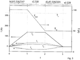
- Fig. 3 illustrates the course of the method as described in Fig. 2 during the nth (i.e. not the first) preparatory cycle or the final cycle of steps. Illustrated is the temperature T bulk of the superconductor bulk magnet (top curve, with the scale of temperature T on the right hand side in Kelvin, compare arrow to the right), as well as the electrical current I 0 applied to the charger magnet and the auxiliary electrical currents I 1 , I 2 , I 3 applied to the field correction unit or the correction coil system, respectively, located inside the superconductor bore (bottom curves, with the scale of current I to the left hand side in Amperes, compare arrows to the left), as a function of time t (in arbitrary units).
- each auxiliary electrical current I 1 , I 2 , I 3 is applied to a separate subset of coils of the correction coil system, with each subset of coils addressing a gradient field contribution of a particular order to the B z component of the auxiliary magnetic field; alternatively, auxiliary electrical currents may simply be assigned to single correction coils directly.
- T bulk is above the critical temperature T c (which is here at about 90K).
- the current I 0 as well as the auxiliary currents I 1 , I 2 , I 3 are ramped up from zero to a respective desired current (note that I 3 here has a negative sign).
- the absolute values of the attained auxiliary currents I 1 , I 2 , I 3 are much lower than the absolute value of current I 0 .
- the currents I 0 and I 1 , I 2 , I 3 are ramped up simultaneously, however alternatively, it is also possible to apply a desired sequence, for example with ramping up I 0 first, and I 1 , I 2 , I 3 afterwards.
- step c) 218 may begin.
- T bulk is lowered to an operating temperature T op , which is below T c , with T op of about 50 K here. So during step c) 218, the superconductor bulk magnet becomes superconducting, and is thus prepared to take over an electrical current by induction.
- step e) 228, which basically indicates the final stage of the superconductor bulk magnet after its magnetization (charging), all currents I 0 , I 1 , I 2 , I 3 have been turned off, and T bulk is kept at T op .
- the superconductor bulk magnet (together with its cryostat) can be removed from the charger magnet bore, and the field correction unit may be removed from the superconductor bore now.
- Fig. 4 illustrates in a schematic cross-section of a part of a correction coil system 36 of a field correction unit 31, namely a subset of coils 51 (see also inset left) of here two correction coils 32a, 32b.
- Said correction coils 32a, 32b of the subset of coils 51 are here of solenoid type and are arranged coaxially with the central axis 5 of the superconductor bore 7 of the superconductor bulk magnet 21. They are electrically connected in series wherein the direction of an auxiliary electrical current provided by field correction current source 33/53 is opposite in the two correction coils 32a, 32b, compare the dots and crosses in the cross-section of the coil windings.
- an auxiliary magnetic field 53 generated by the subset of coils 51 has opposite directions in an upper part and a lower part of the superconductor bore 7, and is basically parallel to the central axis 5. Accordingly, the auxiliary magnetic field 53 generated by the subset of coils 51 represents a first order on-axis gradient field contribution to the z component of the (total) magnetic field B z in the superconductor bore 7. For this reason, the auxiliary magnetic field 53 generated here is also called the linear on-axis correction field.
- the currents in the coils 32a, 32b are transferred to the nearby inner layer of the superconductor bulk magnet 21 by induction, compare trapped currents 54.
- These trapped currents 54 basically maintain the corresponding magnetic field in the superconductor bore 7, i.e. the auxiliary magnetic field 53 is basically conserved.
- Fig. 5 illustrates in a schematic cross-section of a further part of a correction coil system 36 of a field correction unit 31, namely a subset of coils 61 (see also inset left) of here three correction coils 32a, 32b, 32c.
- Said correction coils 32a, 32b, 32c of the subset of coils 61 are again here of solenoid type and are arranged coaxially with the central axis 5 of the superconductor bore 7 of the superconductor bulk magnet 21.
- an auxiliary magnetic field 63 generated by the subset of coils 61 has a first direction in an upper part and a lower part of the superconductor bore 7, and has an opposite second direction in a center part of the superconductor bore 7, and is basically parallel to the central axis 5.
- the auxiliary magnetic field 63 generated by the subset of coils 61 represents a second order on-axis gradient field contribution to the z component of the (total) magnetic field B z in the superconductor bore 7.
- the auxiliary magnetic field 63 generated here is also called the quadratic on-axis correction field.
- the currents in the coils 32a-32c are transferred to the nearby inner layer of the superconductor bulk magnet 21 by induction, compare trapped currents 64.
- These trapped currents 64 basically maintain the corresponding magnetic field in the superconductor bore 7, i.e. the auxiliary magnetic field 63 is basically conserved.
- Fig. 6 illustrates in a schematic cross-section of another further part of a correction coil system 36 of a field correction unit 31, namely a subset of coils 71 (see also inset left) of here four correction coils 32a, 32b, 32c, 32d.
- Said correction coils 32a-32d of the subset of coils 71 are here of saddle type and arranged on the cylindrical holder 8 of the field correction unit 31, with their local saddle coil window axes 75 perpendicular to the central axis 5 of the superconductor bore 7 of the superconductor bulk magnet 21.
- an auxiliary electrical current provided by field correction current source 33/72 has a first direction for the two upper coils 32a, 32c, and has a second direction opposite to the first direction in the two lower coils 32b, 32d, compare the dots and crosses in the cross-section of the coil windings.
- an auxiliary magnetic field 73 generated by the subset of coils 71 has a first direction in a left central part of the superconductor bore 7, and has an opposite second direction in a right central part of the superconductor bore 7, and is basically in parallel to the central axis 5.
- the auxiliary magnetic field 63 generated by the subset of coils 61 represents a first order off-axis gradient field contribution to the z component of the (total) magnetic field B z in the superconductor bore 7.
- the auxiliary magnetic field 73 generated here is also called the linear off-axis correction field. Note that there are also some contributions B x to the auxiliary magnetic field 73 on radially and axially off-center regions, not relevant for the typically used central volume fraction or sample volume SV of the superconductor bore 7.
- the currents in the coils 32a-32d are transferred to the nearby inner layer of the superconductor bulk magnet 21 by induction, compare trapped currents 74.
- These trapped currents 74 basically maintain the corresponding magnetic field in the superconductor bore 7, i.e. the auxiliary magnetic field 73 is trapped.
- the correction coil system 36 may comprise one or a plurality of subsets of coils 51, 61, 71 as shown in Figs. 4 through 6 , and each subset of coils is operated with a separate field correction current source 33 resp. 52, 62, 72.
- Fig. 7 illustrates in a schematic view of a cross-section (or cut face 26) of a superconductor bulk magnet 21, taken along a plane including the central axis 5, and magnetized in accordance with the invention.
- a radially (and to some extend axially) outer part of the superconductor bulk magnet 21 (typically having a volume fraction of 75% or more of the of the superconductor bulk magnet 21) is magnetized by a trapped field current 22, corresponding basically to (or originating from) an electrical current originally present in the charger magnet.
- a radially (and to some extent axially) inner part of the superconductor bulk magnet 21 (typically having a volume fraction of 1% or less of the of the superconductor bulk magnet 21) is magnetized by a trapped correction field current 32, corresponding basically to (or originating from) the auxiliary electrical currents originally present in the field correction unit or its correction coil system.
- a current-free region 24 (typically having a volume fraction of between 10% and 30% of the superconductor bulk magnet 21) remains inside the superconductor bulk magnet 21.
- the electrical current in the charger magnet in step b) has to be set appropriately, and in particular low enough so that the volume of the trapped field current 22 does not go beyond the desired volume fraction in step d). If the volume of the superconductor bulk magnet was completely filled with trapped field current 22, the superconductor bulk magnet would quench, which bears a big risk of permanently damaging the superconductor bulk magnet.
- auxiliary electric currents also called correction currents
- the determination of the set of correction currents for the correction coils is based on the assumption of the validity of the superposition principle for trapped currents, i.e. that the sum of the trapped currents for two successive applications of field-cooling with applied external fields equals the trapped current observed from field-cooling an external field of the sum of the two fields.
- B z 0 z corresponds to the (constant, homogeneous) background field
- ⁇ 1 is the linear on-axis gradient coefficient (compare Fig. 4 )
- ⁇ 2 is the coefficient for the quadratic term (compare Fig. 5 ).
- the correction coil system can, as an example, be implemented in a way so that the currents I 1 , I 2 , ... generate a magnetic field that leads to a trapped field after field-cooling, that has the field profile of a linear, quadratic, ... field-z dependence.
- the coefficients ⁇ i are directly proportional to the correction currents in a respective subset of coils i.
- N is finite in the above expansion, and the measured field profile is not equal exactly to, but only approximated by, the expansion.
- a practical number for N could be between 2 and 4.
- the superposition principle is not applicable, strictly speaking. It assumes that the same region adjacent to the inner wall of the bulk conductor can be simultaneously used to carry current from the individual correction coils. As field-cooling is by default a process that leads to saturated current densities in a given conductor volume, there is no current carrying "budget" left for the "superposing" step.
- the layer of superconductor that is involved in carrying current from field-cooling the comparatively small fields from the correction coils is very thin, of the order of microns.
- the successive step will then just use the "next available" superconductor layer, located a few microns outside the innermost layer. As this distance is very small compared to the overall size of the bulk magnet, the two currents flow in places that are to a high precision identical to the originally assumed "superposed" locations. The effect on the trapped field is virtually indistinguishable.
- the invention relates to a method for magnetizing a superconductor bulk magnet (21), with the following steps:
Claims (15)
- Procédé d'aimantation d'un aimant massif supraconducteur (21), comprenant les étapes consistant à :étape a) (202) placer l'aimant massif supraconducteur (21) à l'intérieur d'un alésage de chargeur (3) d'un aimant de chargeur électrique (1) ; suivie deétape b) (206, 216) appliquer au moins un courant électrique (I0) à l'aimant de chargeur (1), en générant ainsi avec l'aimant de chargeur (1) un champ magnétique (4) lequel est appliqué à l'aimant massif supraconducteur (21) depuis l'extérieur, où une température Tmassif de l'aimant massif supraconducteur (21) est supérieure à une température critique Tc de l'aimant massif supraconducteur (21) ; suivie deétape c) (208, 218) abaisser la température Tmassif de l'aimant massif supraconducteur (21) en dessous de la température critique Tc de l'aimant massif supraconducteur (21) ; suivie deétape d) (210, 220) couper le au moins un courant électrique (I0) au niveau de l'aimant de chargeur (1), où Tmassif < Tc ; suivie deétape e) (228) retirer l'aimant massif supraconducteur (21) de l'alésage de chargeur (3) et maintenir Tmassif < Tc ;caractérisé par
le procédé incluant en outre les étapes consistant àétape a') (204) placer une unité de correction de champ (31) au moins en partie à l'intérieur d'un alésage de supraconducteur (7) de l'aimant massif supraconducteur (21), de telle sorte qu'un système de bobine de correction (36) de l'unité de correction de champ (31) est situé au moins en partie à l'intérieur de l'alésage de supraconducteur (7) ; etétape b') (217) appliquer au moins un courant électrique auxiliaire (I1, I2, I3) à l'unité de correction de champ (31), en générant ainsi avec l'unité de correction de champ (31) un champ magnétique auxiliaire (53 ; 63 ; 73) lequel est appliqué à l'aimant massif supraconducteur (21) à partir de l'intérieur de l'alésage de supraconducteur (7),où Tmassif > Tc,l'étape a') (204) étant réalisée avant l'étape b') (217) et l'étape b') (217) étant réalisée avant l'étape c) (218) ; etétape d') (221) couper le au moins un courant électrique auxiliaire (I1, I2, I3) au niveau de l'unité de correction de champ (31), où Tmassif < Tc,l'étape d') (221) étant réalisée après l'étape c) (218). - Procédé selon la revendication 1, caractérisé en ce
que le procédé inclut au moins un cycle préparatoire d'étapes (232, 234), incluant au moins l'étape b) (206, 216), suivie de l'étape c) (208, 218), suivie de l'étape d) (210, 220), suivie d'une étape f) (212, 222), suivie d'une étape g) (214, 226),
l'étape f) (212, 222) consistant à mesurer un profil de champ magnétique à l'intérieur de l'alésage de supraconducteur (7) de l'aimant massif supraconducteur (21), où Tmassif < Tc, et
l'étape g) (214, 226) consistant à déterminer à partir du profil de champ magnétique mesuré à l'étape f) (212, 222) au moins un courant électrique auxiliaire (I1, I2, I3) à appliquer à l'unité de correction de champ (31) dans un cycle suivant d'étapes (234, 236), et à augmenter la température Tmassif de l'aimant massif supraconducteur (21) au-dessus de la température critique Tc,
et en ce que le procédé comprend un cycle final d'étapes (236), incluant au moins l'étape b) (216) et l'étape b') (217), suivie de l'étape c) (218), suivie de l'étape d) (220) et de l'étape d') (221), suivie de l'étape e) (228),
l'étape b') (217) établissant le au moins un courant électrique auxiliaire (I1, I2, I3) déterminé à l'étape g) (214, 226) du cycle préparatoire précédent d'étapes (232, 234). - Procédé selon la revendication 2, caractérisé en ce que lors d'au moins un cycle préparatoire d'étapes (232, 234), en particulier lors d'un premier cycle préparatoire d'étapes (232), aucun courant électrique auxiliaire (I1, I2, I3) n'est appliqué à l'unité de correction de champ (31).
- Procédé selon la revendication 2 ou 3, caractérisé en ce que au moins un cycle préparatoire d'étapes (232, 234) inclut également l'étape b') (217) réalisée avant l'étape c) (218), et inclut également l'étape d') (221) réalisée après l'étape c) (218) et avant l'étape f) (222).
- Procédé selon l'une des revendications 2 à 4, caractérisé en ce que lors de l'étape f) (212, 222), le profil de champ magnétique dans l'alésage de supraconducteur (7) de l'aimant massif supraconducteur (21) est mesuré avec au moins un capteur de champ magnétique (34) lequel est déplacé le long d'un axe central (5) de l'aimant massif supraconducteur (21) et tourné autour dudit axe central (5).
- Procédé selon l'une des revendications précédentes, caractérisé en ce qu'une composante Bz du champ magnétique auxiliaire (53 ; 63 ; 73) inclut au moins un ordre, de préférence au moins deux ordres, de contributions de champ à gradient sur axe (53 ; 63), z étant parallèle à un axe central (5) de l'alésage de supraconducteur (7), et les contributions de champ sur axe étant obtenues par calcul de dérivée de Bz par rapport à z.
- Procédé selon l'une des revendications précédentes, caractérisé en ce qu'une composante Bz du champ magnétique auxiliaire (53 ; 63 ; 73) comprend des contributions de champ à gradient hors axe (73), z étant parallèle à un axe central (5) de l'alésage de supraconducteur (7), et les contributions de champ hors axe étant obtenues par calcul de dérivée de Bz par rapport à x et/ou à y, x, y, z formant un système de coordonnées cartésiennes.
- Procédé selon l'une des revendications précédentes, caractérisé en ce que l'unité de correction de champ (UCC) (31) est maintenue à une température TUCC qui est sensiblement supérieure à la température Tmassif de l'aimant massif supraconducteur (21) au cours du procédé, TUCC ≥ Tmassif + 50 K.
- Procédé selon l'une des revendications précédentes, caractérisé en ce que l'étape e) (228) inclut en outre le fait de retirer l'unité de correction de champ (21) de l'alésage de supraconducteur (7) de l'aimant massif supraconducteur (21), et le fait de transporter l'aimant massif supraconducteur aimanté (21) sans l'aimant de chargeur (1) et sans l'unité de correction de champ (31) vers un site d'application.
- Dispositif (100) d'aimantation d'un aimant massif supraconducteur (21), en particulier destiné à être utilisé dans un procédé selon l'une des revendications précédentes, le dispositif (100) comprenant- un aimant de chargeur électrique (1) destiné à générer un champ magnétique (4), l'aimant de chargeur (1) présentant un alésage de chargeur (3) ;- un cryostat (11) présentant un alésage à température ambiante (12), où le cryostat (11) est situé au moins en partie à l'intérieur de l'alésage de chargeur (3) ;- un aimant massif supraconducteur (21) situé à l'intérieur du cryostat (11), de telle sorte que l'aimant massif supraconducteur (21) est situé à l'intérieur de l'alésage de chargeur (3), et l'aimant massif supraconducteur (21) peut subir une aimantation au moyen du champ magnétique (4) généré par l'aimant de chargeur électrique (1), et de telle sorte que l'alésage à température ambiante (12) du cryostat (11) est au moins en partie situé à l'intérieur de l'alésage de supraconducteur (7) de l'aimant massif supraconducteur (21), l'alésage de supraconducteur (7) étant un espace s'étendant de manière radiale et axiale à l'intérieur de l'aimant massif supraconducteur (21), où l'alésage de chargeur (3), l'alésage de supraconducteur (7) et l'alésage à température ambiante (12) sont agencés de manière coaxiale, en partageant un axe central commun (5) définissant une direction z, et le champ magnétique (4) généré par l'aimant de chargeur (1) étant principalement parallèle à la direction z, et où l'aimant massif supraconducteur (21) présente une température critique Tc et le cryostat (11) est conçu pour atteindre une température inférieure à Tc ;- une unité de correction de champ (31), située à l'extérieur du cryostat (11) et au moins en partie à l'intérieur de l'alésage à température ambiante (12) du cryostat (11), l'unité de correction de champ (31) comprenant un système de bobine de correction (36) destiné à générer un champ magnétique auxiliaire (53 ; 63 ; 73), ledit système de bobine de correction (36) étant situé au moins en partie, et de préférence complètement, à l'intérieur de l'alésage de supraconducteur (7),où le dispositif est conçu pour appliquer à la fois au moins un courant électrique (I0) à l'aimant de chargeur (1) et au moins un courant électrique auxiliaire (I1, I2, I3) à l'unité de correction de champ (31) en même temps, pour établir une superposition du champ magnétique (4) généré par l'aimant de chargeur (1) et du champ magnétique auxiliaire (53 ; 63 ; 73) généré par l'unité de correction de champ (31) pénétrant l'aimant massif supraconducteur (21).
- Dispositif (100) selon la revendication 10, caractérisé en ce que l'unité de correction de champ (31) comprend en outre au moins un capteur de champ magnétique (34), en particulier un capteur de Hall.
- Dispositif (100) selon la revendication 11, caractérisé en ce qu'un ou une pluralité de capteurs de champ magnétique (34) du au moins un capteur de champ magnétique (34) est placé à une certaine distance radiale par rapport à un axe central (5) de l'alésage à température ambiante (12).
- Dispositif (100) selon l'une des revendications 10 à 12, caractérisé en ce que l'unité de correction de champ (31) est équipée d'un mécanisme (35), en particulier d'un mécanisme motorisé (35), destiné à déplacer l'unité de correction de champ (31) le long d'un axe central (5) de l'alésage à température ambiante (12) et destiné à faire tourner l'unité de correction de champ (31) autour de l'axe central (5) de l'alésage à température ambiante (12).
- Dispositif (100) selon l'une des revendications 10 à 13, caractérisé en ce que l'unité de correction de champ (31) comprend au moins un sous-ensemble de bobines (51 ; 61) destiné à générer une contribution de champ à gradient sur axe au moins du premier ordre (53 ; 63) à une composante Bz du champ magnétique auxiliaire (53 ; 63 ; 73), en particulier où l'unité de correction de champ (31) comprend au moins deux sous-ensembles de bobines (51 ; 61) destiné à générer des contributions de champ à gradient sur axe au moins des premier et second ordres (53 ; 63) à la composante Bz du champ magnétique auxiliaire (53 ; 63 ; 73).
- Dispositif (100) selon l'une des revendications 10 à 14, caractérisé en ce que l'unité de correction de champ (31) comprend au moins un sous-ensemble de bobines (71) destiné à générer une contribution de champ à gradient hors axe (73) à une composante Bz du champ magnétique auxiliaire (53 ; 63 ; 73).
Priority Applications (3)
| Application Number | Priority Date | Filing Date | Title |
|---|---|---|---|
| EP18207267.8A EP3657193B1 (fr) | 2018-11-20 | 2018-11-20 | Procédé de magnétisation d'un aimant supraconducteur, avec génération d'un champ magnétique auxiliaire dans l'alésage de supraconducteur |
| JP2019207377A JP6861263B2 (ja) | 2018-11-20 | 2019-11-15 | 超伝導ボアに補助磁場を発生させることによる、超伝導バルク磁石を着磁するための方法 |
| US16/689,145 US11551843B2 (en) | 2018-11-20 | 2019-11-20 | Method for magnetizing a superconductor bulk magnet, with generating an auxiliary magnetic field in the superconductor bore |
Applications Claiming Priority (1)
| Application Number | Priority Date | Filing Date | Title |
|---|---|---|---|
| EP18207267.8A EP3657193B1 (fr) | 2018-11-20 | 2018-11-20 | Procédé de magnétisation d'un aimant supraconducteur, avec génération d'un champ magnétique auxiliaire dans l'alésage de supraconducteur |
Publications (2)
| Publication Number | Publication Date |
|---|---|
| EP3657193A1 EP3657193A1 (fr) | 2020-05-27 |
| EP3657193B1 true EP3657193B1 (fr) | 2021-02-17 |
Family
ID=64402094
Family Applications (1)
| Application Number | Title | Priority Date | Filing Date |
|---|---|---|---|
| EP18207267.8A Active EP3657193B1 (fr) | 2018-11-20 | 2018-11-20 | Procédé de magnétisation d'un aimant supraconducteur, avec génération d'un champ magnétique auxiliaire dans l'alésage de supraconducteur |
Country Status (3)
| Country | Link |
|---|---|
| US (1) | US11551843B2 (fr) |
| EP (1) | EP3657193B1 (fr) |
| JP (1) | JP6861263B2 (fr) |
Cited By (1)
| Publication number | Priority date | Publication date | Assignee | Title |
|---|---|---|---|---|
| EP4080527A1 (fr) * | 2021-04-20 | 2022-10-26 | Bruker Switzerland AG | Procédé pour charger un système d'aimant supraconducteur avec système de refroidissement séquentiel avec des sous-aimants supraconducteurs en vrac |
Families Citing this family (4)
| Publication number | Priority date | Publication date | Assignee | Title |
|---|---|---|---|---|
| DE102018221322A1 (de) * | 2018-12-10 | 2020-06-10 | Bruker Switzerland Ag | Verfahren zum Laden einer HTS-Shim-Vorrichtung und Magnetanordnung |
| EP3822992B1 (fr) | 2019-11-14 | 2023-09-06 | Bruker Switzerland AG | Procédé pour charger un système magnétique supraconducteur comportant un aimant massif supraconducteur principal et un aimant massif supraconducteur de blindage |
| EP4053860B1 (fr) * | 2021-03-05 | 2023-06-21 | Bruker Switzerland AG | Procédé de charge d'un aimant massif supraconducteur par refroidissement de champ, avec au moins un composant de champ magnétique non homogène du champ magnétique du chargeur appliqué |
| EP4177624A1 (fr) | 2021-11-09 | 2023-05-10 | Bruker Switzerland AG | Procédé d'homogénéisation d'un profil de champ magnétique d'un système d'aimant supraconducteur, en particulier avec une rétroaction par un profil de champ magnétique mesuré |
Family Cites Families (13)
| Publication number | Priority date | Publication date | Assignee | Title |
|---|---|---|---|---|
| JPH0974012A (ja) * | 1994-09-16 | 1997-03-18 | Hitachi Medical Corp | 超電導多層複合体を用いた超電導磁石装置と着磁方法 |
| JPH11248810A (ja) | 1998-02-27 | 1999-09-17 | Rikagaku Kenkyusho | 核磁気共鳴装置 |
| US6169401B1 (en) | 1998-11-25 | 2001-01-02 | Picker International, Inc. | Flexible open quadrature highpass ladder structure RF surface coil in magnetic resonance imaging |
| JP2000262486A (ja) * | 1999-03-17 | 2000-09-26 | Hitachi Ltd | 静磁場発生装置及び方法 |
| JP2002008917A (ja) * | 2000-06-26 | 2002-01-11 | Inst Of Physical & Chemical Res | 超伝導体磁場応用装置の制御方法とこの方法を用いた核磁気共鳴装置と超伝導磁石装置 |
| WO2007041532A2 (fr) | 2005-10-03 | 2007-04-12 | Massachusetts Institute Of Technology | Systeme d'aimant annulaire pour spectroscopie par resonance magnetique |
| CN101236239B (zh) * | 2007-01-30 | 2012-01-25 | 西门子(中国)有限公司 | 磁共振系统的超导磁体的电流引线 |
| EP2511917B1 (fr) | 2009-12-08 | 2018-11-14 | Nippon Steel & Sumitomo Metal Corporation | Élément à aimant massif supraconducteur à base d'oxyde |
| JP6090557B2 (ja) * | 2012-09-07 | 2017-03-08 | アイシン精機株式会社 | 超電導体、超電導磁石、超電導磁場発生装置及び核磁気共鳴装置 |
| JPWO2015015892A1 (ja) | 2013-07-31 | 2017-03-02 | 株式会社日立製作所 | 磁場発生装置、それを用いた磁気共鳴イメージング装置、および、高温超電導バルク体の着磁装置 |
| JP6402501B2 (ja) | 2014-06-20 | 2018-10-10 | アイシン精機株式会社 | 超電導磁場発生装置、超電導磁場発生方法及び核磁気共鳴装置 |
| BR112017004336A2 (pt) * | 2014-09-05 | 2017-12-05 | Hyperfine Res Inc | métodos e aparelhos de formação de imagem por ressonância magnética de campo baixo |
| JP2016168265A (ja) * | 2015-03-13 | 2016-09-23 | 株式会社日立製作所 | 磁気共鳴イメージング装置、および、その運転方法 |
-
2018
- 2018-11-20 EP EP18207267.8A patent/EP3657193B1/fr active Active
-
2019
- 2019-11-15 JP JP2019207377A patent/JP6861263B2/ja active Active
- 2019-11-20 US US16/689,145 patent/US11551843B2/en active Active
Non-Patent Citations (1)
| Title |
|---|
| None * |
Cited By (1)
| Publication number | Priority date | Publication date | Assignee | Title |
|---|---|---|---|---|
| EP4080527A1 (fr) * | 2021-04-20 | 2022-10-26 | Bruker Switzerland AG | Procédé pour charger un système d'aimant supraconducteur avec système de refroidissement séquentiel avec des sous-aimants supraconducteurs en vrac |
Also Published As
| Publication number | Publication date |
|---|---|
| JP2020106521A (ja) | 2020-07-09 |
| US20200161039A1 (en) | 2020-05-21 |
| JP6861263B2 (ja) | 2021-04-21 |
| US11551843B2 (en) | 2023-01-10 |
| EP3657193A1 (fr) | 2020-05-27 |
Similar Documents
| Publication | Publication Date | Title |
|---|---|---|
| EP3657193B1 (fr) | Procédé de magnétisation d'un aimant supraconducteur, avec génération d'un champ magnétique auxiliaire dans l'alésage de supraconducteur | |
| US7701218B2 (en) | Magnet assembly | |
| EP0975987B8 (fr) | Reduction de la susceptibilite magnetique effective de bobines r.f. supraconductrices dans des sondes a resonance magnetique nucleaire (rmn) | |
| US6054855A (en) | Magnetic susceptibility control of superconducting materials in nuclear magnetic resonance (NMR) probes | |
| Ahn et al. | 3-D field mapping and active shimming of a screening-current-induced field in an HTS coil using harmonic analysis for high-resolution NMR magnets | |
| US11798720B2 (en) | Superconductor magnet system, with individual temperature control of axially stacked bulk sub-magnets | |
| US11527343B2 (en) | Method for charging a superconductor magnet system, with a main superconductor bulk magnet and a shield superconductor bulk magnet | |
| US10998127B2 (en) | Superconducting magnet apparatus and method for magnetizing a superconductor bulk magnet by field cooling through a ferromagnetic shield | |
| EP4080527B1 (fr) | Procédé pour charger un système d'aimant supraconducteur avec système de refroidissement séquentiel avec des sous-aimants supraconducteurs en vrac | |
| Kim et al. | Development of HTS bulk NMR relaxometry with ring-shaped iron | |
| US20220285060A1 (en) | A method for charging a superconductor bulk magnet by field-cooling, with at least one non-homogeneous magnetic field component of the applied charger magnetic field | |
| US11875936B2 (en) | Method for homogenizing a magnetic field profile of a superconductor magnet system | |
| US6972652B2 (en) | Method for homogenizing a super-conducting NMR magnet | |
| Maki et al. | Development of shimming system for a highly sensitive NMR spectrometer with a superconducting split magnet | |
| Miyazaki et al. | First Vertical Test of a Prototype Crab Cavity for HL-LHC at FREIA Laboratory in Uppsala University | |
| Wheatley et al. | Temporal stability of circulating current in thin film Tl/sub 2/Ba/sub 2/CaCu/sub 2/O/sub 8/and YBa/sub 2/Cu/sub 3/O/sub 7 |
Legal Events
| Date | Code | Title | Description |
|---|---|---|---|
| PUAI | Public reference made under article 153(3) epc to a published international application that has entered the european phase |
Free format text: ORIGINAL CODE: 0009012 |
|
| STAA | Information on the status of an ep patent application or granted ep patent |
Free format text: STATUS: REQUEST FOR EXAMINATION WAS MADE |
|
| 17P | Request for examination filed |
Effective date: 20191015 |
|
| AK | Designated contracting states |
Kind code of ref document: A1 Designated state(s): AL AT BE BG CH CY CZ DE DK EE ES FI FR GB GR HR HU IE IS IT LI LT LU LV MC MK MT NL NO PL PT RO RS SE SI SK SM TR |
|
| AX | Request for extension of the european patent |
Extension state: BA ME |
|
| GRAP | Despatch of communication of intention to grant a patent |
Free format text: ORIGINAL CODE: EPIDOSNIGR1 |
|
| STAA | Information on the status of an ep patent application or granted ep patent |
Free format text: STATUS: GRANT OF PATENT IS INTENDED |
|
| INTG | Intention to grant announced |
Effective date: 20200612 |
|
| GRAJ | Information related to disapproval of communication of intention to grant by the applicant or resumption of examination proceedings by the epo deleted |
Free format text: ORIGINAL CODE: EPIDOSDIGR1 |
|
| STAA | Information on the status of an ep patent application or granted ep patent |
Free format text: STATUS: REQUEST FOR EXAMINATION WAS MADE |
|
| INTC | Intention to grant announced (deleted) | ||
| GRAP | Despatch of communication of intention to grant a patent |
Free format text: ORIGINAL CODE: EPIDOSNIGR1 |
|
| STAA | Information on the status of an ep patent application or granted ep patent |
Free format text: STATUS: GRANT OF PATENT IS INTENDED |
|
| GRAS | Grant fee paid |
Free format text: ORIGINAL CODE: EPIDOSNIGR3 |
|
| INTG | Intention to grant announced |
Effective date: 20201102 |
|
| GRAA | (expected) grant |
Free format text: ORIGINAL CODE: 0009210 |
|
| STAA | Information on the status of an ep patent application or granted ep patent |
Free format text: STATUS: THE PATENT HAS BEEN GRANTED |
|
| AK | Designated contracting states |
Kind code of ref document: B1 Designated state(s): AL AT BE BG CH CY CZ DE DK EE ES FI FR GB GR HR HU IE IS IT LI LT LU LV MC MK MT NL NO PL PT RO RS SE SI SK SM TR |
|
| REG | Reference to a national code |
Ref country code: GB Ref legal event code: FG4D |
|
| REG | Reference to a national code |
Ref country code: CH Ref legal event code: EP |
|
| REG | Reference to a national code |
Ref country code: DE Ref legal event code: R096 Ref document number: 602018012609 Country of ref document: DE |
|
| REG | Reference to a national code |
Ref country code: AT Ref legal event code: REF Ref document number: 1362159 Country of ref document: AT Kind code of ref document: T Effective date: 20210315 |
|
| REG | Reference to a national code |
Ref country code: IE Ref legal event code: FG4D |
|
| REG | Reference to a national code |
Ref country code: LT Ref legal event code: MG9D |
|
| REG | Reference to a national code |
Ref country code: NL Ref legal event code: MP Effective date: 20210217 |
|
| PG25 | Lapsed in a contracting state [announced via postgrant information from national office to epo] |
Ref country code: BG Free format text: LAPSE BECAUSE OF FAILURE TO SUBMIT A TRANSLATION OF THE DESCRIPTION OR TO PAY THE FEE WITHIN THE PRESCRIBED TIME-LIMIT Effective date: 20210517 Ref country code: HR Free format text: LAPSE BECAUSE OF FAILURE TO SUBMIT A TRANSLATION OF THE DESCRIPTION OR TO PAY THE FEE WITHIN THE PRESCRIBED TIME-LIMIT Effective date: 20210217 Ref country code: GR Free format text: LAPSE BECAUSE OF FAILURE TO SUBMIT A TRANSLATION OF THE DESCRIPTION OR TO PAY THE FEE WITHIN THE PRESCRIBED TIME-LIMIT Effective date: 20210518 Ref country code: FI Free format text: LAPSE BECAUSE OF FAILURE TO SUBMIT A TRANSLATION OF THE DESCRIPTION OR TO PAY THE FEE WITHIN THE PRESCRIBED TIME-LIMIT Effective date: 20210217 Ref country code: PT Free format text: LAPSE BECAUSE OF FAILURE TO SUBMIT A TRANSLATION OF THE DESCRIPTION OR TO PAY THE FEE WITHIN THE PRESCRIBED TIME-LIMIT Effective date: 20210617 Ref country code: NO Free format text: LAPSE BECAUSE OF FAILURE TO SUBMIT A TRANSLATION OF THE DESCRIPTION OR TO PAY THE FEE WITHIN THE PRESCRIBED TIME-LIMIT Effective date: 20210517 Ref country code: LT Free format text: LAPSE BECAUSE OF FAILURE TO SUBMIT A TRANSLATION OF THE DESCRIPTION OR TO PAY THE FEE WITHIN THE PRESCRIBED TIME-LIMIT Effective date: 20210217 |
|
| REG | Reference to a national code |
Ref country code: AT Ref legal event code: MK05 Ref document number: 1362159 Country of ref document: AT Kind code of ref document: T Effective date: 20210217 |
|
| PG25 | Lapsed in a contracting state [announced via postgrant information from national office to epo] |
Ref country code: RS Free format text: LAPSE BECAUSE OF FAILURE TO SUBMIT A TRANSLATION OF THE DESCRIPTION OR TO PAY THE FEE WITHIN THE PRESCRIBED TIME-LIMIT Effective date: 20210217 Ref country code: LV Free format text: LAPSE BECAUSE OF FAILURE TO SUBMIT A TRANSLATION OF THE DESCRIPTION OR TO PAY THE FEE WITHIN THE PRESCRIBED TIME-LIMIT Effective date: 20210217 Ref country code: PL Free format text: LAPSE BECAUSE OF FAILURE TO SUBMIT A TRANSLATION OF THE DESCRIPTION OR TO PAY THE FEE WITHIN THE PRESCRIBED TIME-LIMIT Effective date: 20210217 Ref country code: NL Free format text: LAPSE BECAUSE OF FAILURE TO SUBMIT A TRANSLATION OF THE DESCRIPTION OR TO PAY THE FEE WITHIN THE PRESCRIBED TIME-LIMIT Effective date: 20210217 Ref country code: SE Free format text: LAPSE BECAUSE OF FAILURE TO SUBMIT A TRANSLATION OF THE DESCRIPTION OR TO PAY THE FEE WITHIN THE PRESCRIBED TIME-LIMIT Effective date: 20210217 |
|
| PG25 | Lapsed in a contracting state [announced via postgrant information from national office to epo] |
Ref country code: IS Free format text: LAPSE BECAUSE OF FAILURE TO SUBMIT A TRANSLATION OF THE DESCRIPTION OR TO PAY THE FEE WITHIN THE PRESCRIBED TIME-LIMIT Effective date: 20210617 |
|
| PG25 | Lapsed in a contracting state [announced via postgrant information from national office to epo] |
Ref country code: EE Free format text: LAPSE BECAUSE OF FAILURE TO SUBMIT A TRANSLATION OF THE DESCRIPTION OR TO PAY THE FEE WITHIN THE PRESCRIBED TIME-LIMIT Effective date: 20210217 Ref country code: CZ Free format text: LAPSE BECAUSE OF FAILURE TO SUBMIT A TRANSLATION OF THE DESCRIPTION OR TO PAY THE FEE WITHIN THE PRESCRIBED TIME-LIMIT Effective date: 20210217 Ref country code: SM Free format text: LAPSE BECAUSE OF FAILURE TO SUBMIT A TRANSLATION OF THE DESCRIPTION OR TO PAY THE FEE WITHIN THE PRESCRIBED TIME-LIMIT Effective date: 20210217 Ref country code: AT Free format text: LAPSE BECAUSE OF FAILURE TO SUBMIT A TRANSLATION OF THE DESCRIPTION OR TO PAY THE FEE WITHIN THE PRESCRIBED TIME-LIMIT Effective date: 20210217 |
|
| REG | Reference to a national code |
Ref country code: DE Ref legal event code: R097 Ref document number: 602018012609 Country of ref document: DE |
|
| PG25 | Lapsed in a contracting state [announced via postgrant information from national office to epo] |
Ref country code: DK Free format text: LAPSE BECAUSE OF FAILURE TO SUBMIT A TRANSLATION OF THE DESCRIPTION OR TO PAY THE FEE WITHIN THE PRESCRIBED TIME-LIMIT Effective date: 20210217 Ref country code: SK Free format text: LAPSE BECAUSE OF FAILURE TO SUBMIT A TRANSLATION OF THE DESCRIPTION OR TO PAY THE FEE WITHIN THE PRESCRIBED TIME-LIMIT Effective date: 20210217 Ref country code: RO Free format text: LAPSE BECAUSE OF FAILURE TO SUBMIT A TRANSLATION OF THE DESCRIPTION OR TO PAY THE FEE WITHIN THE PRESCRIBED TIME-LIMIT Effective date: 20210217 |
|
| PLBE | No opposition filed within time limit |
Free format text: ORIGINAL CODE: 0009261 |
|
| STAA | Information on the status of an ep patent application or granted ep patent |
Free format text: STATUS: NO OPPOSITION FILED WITHIN TIME LIMIT |
|
| 26N | No opposition filed |
Effective date: 20211118 |
|
| PG25 | Lapsed in a contracting state [announced via postgrant information from national office to epo] |
Ref country code: ES Free format text: LAPSE BECAUSE OF FAILURE TO SUBMIT A TRANSLATION OF THE DESCRIPTION OR TO PAY THE FEE WITHIN THE PRESCRIBED TIME-LIMIT Effective date: 20210217 Ref country code: AL Free format text: LAPSE BECAUSE OF FAILURE TO SUBMIT A TRANSLATION OF THE DESCRIPTION OR TO PAY THE FEE WITHIN THE PRESCRIBED TIME-LIMIT Effective date: 20210217 |
|
| PG25 | Lapsed in a contracting state [announced via postgrant information from national office to epo] |
Ref country code: IT Free format text: LAPSE BECAUSE OF FAILURE TO SUBMIT A TRANSLATION OF THE DESCRIPTION OR TO PAY THE FEE WITHIN THE PRESCRIBED TIME-LIMIT Effective date: 20210217 |
|
| PG25 | Lapsed in a contracting state [announced via postgrant information from national office to epo] |
Ref country code: IS Free format text: LAPSE BECAUSE OF FAILURE TO SUBMIT A TRANSLATION OF THE DESCRIPTION OR TO PAY THE FEE WITHIN THE PRESCRIBED TIME-LIMIT Effective date: 20210617 |
|
| PG25 | Lapsed in a contracting state [announced via postgrant information from national office to epo] |
Ref country code: MC Free format text: LAPSE BECAUSE OF FAILURE TO SUBMIT A TRANSLATION OF THE DESCRIPTION OR TO PAY THE FEE WITHIN THE PRESCRIBED TIME-LIMIT Effective date: 20210217 |
|
| PG25 | Lapsed in a contracting state [announced via postgrant information from national office to epo] |
Ref country code: LU Free format text: LAPSE BECAUSE OF NON-PAYMENT OF DUE FEES Effective date: 20211120 Ref country code: BE Free format text: LAPSE BECAUSE OF NON-PAYMENT OF DUE FEES Effective date: 20211130 |
|
| REG | Reference to a national code |
Ref country code: BE Ref legal event code: MM Effective date: 20211130 |
|
| PG25 | Lapsed in a contracting state [announced via postgrant information from national office to epo] |
Ref country code: IE Free format text: LAPSE BECAUSE OF NON-PAYMENT OF DUE FEES Effective date: 20211120 |
|
| PG25 | Lapsed in a contracting state [announced via postgrant information from national office to epo] |
Ref country code: CY Free format text: LAPSE BECAUSE OF FAILURE TO SUBMIT A TRANSLATION OF THE DESCRIPTION OR TO PAY THE FEE WITHIN THE PRESCRIBED TIME-LIMIT Effective date: 20210217 |
|
| PG25 | Lapsed in a contracting state [announced via postgrant information from national office to epo] |
Ref country code: HU Free format text: LAPSE BECAUSE OF FAILURE TO SUBMIT A TRANSLATION OF THE DESCRIPTION OR TO PAY THE FEE WITHIN THE PRESCRIBED TIME-LIMIT; INVALID AB INITIO Effective date: 20181120 |
|
| PG25 | Lapsed in a contracting state [announced via postgrant information from national office to epo] |
Ref country code: SI Free format text: LAPSE BECAUSE OF FAILURE TO SUBMIT A TRANSLATION OF THE DESCRIPTION OR TO PAY THE FEE WITHIN THE PRESCRIBED TIME-LIMIT Effective date: 20210217 |
|
| PGFP | Annual fee paid to national office [announced via postgrant information from national office to epo] |
Ref country code: GB Payment date: 20231123 Year of fee payment: 6 |
|
| P01 | Opt-out of the competence of the unified patent court (upc) registered |
Effective date: 20231221 |
|
| PGFP | Annual fee paid to national office [announced via postgrant information from national office to epo] |
Ref country code: FR Payment date: 20231122 Year of fee payment: 6 Ref country code: DE Payment date: 20231120 Year of fee payment: 6 Ref country code: CH Payment date: 20231201 Year of fee payment: 6 |