EP3656942A1 - Structure and method for connecting a composite insulation exterior wall panel and a steel structural beam-column - Google Patents
Structure and method for connecting a composite insulation exterior wall panel and a steel structural beam-column Download PDFInfo
- Publication number
- EP3656942A1 EP3656942A1 EP19205067.2A EP19205067A EP3656942A1 EP 3656942 A1 EP3656942 A1 EP 3656942A1 EP 19205067 A EP19205067 A EP 19205067A EP 3656942 A1 EP3656942 A1 EP 3656942A1
- Authority
- EP
- European Patent Office
- Prior art keywords
- steel structural
- composite insulation
- insulation panel
- steel
- column
- Prior art date
- Legal status (The legal status is an assumption and is not a legal conclusion. Google has not performed a legal analysis and makes no representation as to the accuracy of the status listed.)
- Granted
Links
Images


Classifications
-
- E—FIXED CONSTRUCTIONS
- E04—BUILDING
- E04B—GENERAL BUILDING CONSTRUCTIONS; WALLS, e.g. PARTITIONS; ROOFS; FLOORS; CEILINGS; INSULATION OR OTHER PROTECTION OF BUILDINGS
- E04B2/00—Walls, e.g. partitions, for buildings; Wall construction with regard to insulation; Connections specially adapted to walls
-
- E—FIXED CONSTRUCTIONS
- E04—BUILDING
- E04C—STRUCTURAL ELEMENTS; BUILDING MATERIALS
- E04C2/00—Building elements of relatively thin form for the construction of parts of buildings, e.g. sheet materials, slabs, or panels
- E04C2/02—Building elements of relatively thin form for the construction of parts of buildings, e.g. sheet materials, slabs, or panels characterised by specified materials
- E04C2/26—Building elements of relatively thin form for the construction of parts of buildings, e.g. sheet materials, slabs, or panels characterised by specified materials composed of materials covered by two or more of groups E04C2/04, E04C2/08, E04C2/10 or of materials covered by one of these groups with a material not specified in one of the groups
- E04C2/284—Building elements of relatively thin form for the construction of parts of buildings, e.g. sheet materials, slabs, or panels characterised by specified materials composed of materials covered by two or more of groups E04C2/04, E04C2/08, E04C2/10 or of materials covered by one of these groups with a material not specified in one of the groups at least one of the materials being insulating
-
- E—FIXED CONSTRUCTIONS
- E04—BUILDING
- E04B—GENERAL BUILDING CONSTRUCTIONS; WALLS, e.g. PARTITIONS; ROOFS; FLOORS; CEILINGS; INSULATION OR OTHER PROTECTION OF BUILDINGS
- E04B1/00—Constructions in general; Structures which are not restricted either to walls, e.g. partitions, or floors or ceilings or roofs
- E04B1/38—Connections for building structures in general
-
- E—FIXED CONSTRUCTIONS
- E04—BUILDING
- E04B—GENERAL BUILDING CONSTRUCTIONS; WALLS, e.g. PARTITIONS; ROOFS; FLOORS; CEILINGS; INSULATION OR OTHER PROTECTION OF BUILDINGS
- E04B1/00—Constructions in general; Structures which are not restricted either to walls, e.g. partitions, or floors or ceilings or roofs
- E04B1/38—Connections for building structures in general
- E04B1/388—Separate connecting elements
-
- E—FIXED CONSTRUCTIONS
- E04—BUILDING
- E04B—GENERAL BUILDING CONSTRUCTIONS; WALLS, e.g. PARTITIONS; ROOFS; FLOORS; CEILINGS; INSULATION OR OTHER PROTECTION OF BUILDINGS
- E04B1/00—Constructions in general; Structures which are not restricted either to walls, e.g. partitions, or floors or ceilings or roofs
- E04B1/62—Insulation or other protection; Elements or use of specified material therefor
- E04B1/74—Heat, sound or noise insulation, absorption, or reflection; Other building methods affording favourable thermal or acoustical conditions, e.g. accumulating of heat within walls
- E04B1/76—Heat, sound or noise insulation, absorption, or reflection; Other building methods affording favourable thermal or acoustical conditions, e.g. accumulating of heat within walls specifically with respect to heat only
-
- E—FIXED CONSTRUCTIONS
- E04—BUILDING
- E04B—GENERAL BUILDING CONSTRUCTIONS; WALLS, e.g. PARTITIONS; ROOFS; FLOORS; CEILINGS; INSULATION OR OTHER PROTECTION OF BUILDINGS
- E04B1/00—Constructions in general; Structures which are not restricted either to walls, e.g. partitions, or floors or ceilings or roofs
- E04B1/62—Insulation or other protection; Elements or use of specified material therefor
- E04B1/74—Heat, sound or noise insulation, absorption, or reflection; Other building methods affording favourable thermal or acoustical conditions, e.g. accumulating of heat within walls
- E04B1/76—Heat, sound or noise insulation, absorption, or reflection; Other building methods affording favourable thermal or acoustical conditions, e.g. accumulating of heat within walls specifically with respect to heat only
- E04B1/762—Exterior insulation of exterior walls
-
- E—FIXED CONSTRUCTIONS
- E04—BUILDING
- E04B—GENERAL BUILDING CONSTRUCTIONS; WALLS, e.g. PARTITIONS; ROOFS; FLOORS; CEILINGS; INSULATION OR OTHER PROTECTION OF BUILDINGS
- E04B1/00—Constructions in general; Structures which are not restricted either to walls, e.g. partitions, or floors or ceilings or roofs
- E04B1/62—Insulation or other protection; Elements or use of specified material therefor
- E04B1/74—Heat, sound or noise insulation, absorption, or reflection; Other building methods affording favourable thermal or acoustical conditions, e.g. accumulating of heat within walls
- E04B1/76—Heat, sound or noise insulation, absorption, or reflection; Other building methods affording favourable thermal or acoustical conditions, e.g. accumulating of heat within walls specifically with respect to heat only
- E04B1/78—Heat insulating elements
- E04B1/80—Heat insulating elements slab-shaped
-
- E—FIXED CONSTRUCTIONS
- E04—BUILDING
- E04B—GENERAL BUILDING CONSTRUCTIONS; WALLS, e.g. PARTITIONS; ROOFS; FLOORS; CEILINGS; INSULATION OR OTHER PROTECTION OF BUILDINGS
- E04B1/00—Constructions in general; Structures which are not restricted either to walls, e.g. partitions, or floors or ceilings or roofs
- E04B1/62—Insulation or other protection; Elements or use of specified material therefor
- E04B1/92—Protection against other undesired influences or dangers
- E04B1/94—Protection against other undesired influences or dangers against fire
- E04B1/941—Building elements specially adapted therefor
- E04B1/942—Building elements specially adapted therefor slab-shaped
-
- E—FIXED CONSTRUCTIONS
- E04—BUILDING
- E04B—GENERAL BUILDING CONSTRUCTIONS; WALLS, e.g. PARTITIONS; ROOFS; FLOORS; CEILINGS; INSULATION OR OTHER PROTECTION OF BUILDINGS
- E04B2/00—Walls, e.g. partitions, for buildings; Wall construction with regard to insulation; Connections specially adapted to walls
- E04B2/88—Curtain walls
- E04B2/90—Curtain walls comprising panels directly attached to the structure
-
- E—FIXED CONSTRUCTIONS
- E04—BUILDING
- E04B—GENERAL BUILDING CONSTRUCTIONS; WALLS, e.g. PARTITIONS; ROOFS; FLOORS; CEILINGS; INSULATION OR OTHER PROTECTION OF BUILDINGS
- E04B1/00—Constructions in general; Structures which are not restricted either to walls, e.g. partitions, or floors or ceilings or roofs
- E04B1/02—Structures consisting primarily of load-supporting, block-shaped, or slab-shaped elements
- E04B1/12—Structures consisting primarily of load-supporting, block-shaped, or slab-shaped elements the elements consisting of other material
-
- E—FIXED CONSTRUCTIONS
- E04—BUILDING
- E04B—GENERAL BUILDING CONSTRUCTIONS; WALLS, e.g. PARTITIONS; ROOFS; FLOORS; CEILINGS; INSULATION OR OTHER PROTECTION OF BUILDINGS
- E04B2/00—Walls, e.g. partitions, for buildings; Wall construction with regard to insulation; Connections specially adapted to walls
- E04B2/02—Walls, e.g. partitions, for buildings; Wall construction with regard to insulation; Connections specially adapted to walls built-up from layers of building elements
- E04B2/04—Walls having neither cavities between, nor in, the solid elements
-
- E—FIXED CONSTRUCTIONS
- E04—BUILDING
- E04C—STRUCTURAL ELEMENTS; BUILDING MATERIALS
- E04C2/00—Building elements of relatively thin form for the construction of parts of buildings, e.g. sheet materials, slabs, or panels
- E04C2/02—Building elements of relatively thin form for the construction of parts of buildings, e.g. sheet materials, slabs, or panels characterised by specified materials
- E04C2/10—Building elements of relatively thin form for the construction of parts of buildings, e.g. sheet materials, slabs, or panels characterised by specified materials of wood, fibres, chips, vegetable stems, or the like; of plastics; of foamed products
- E04C2/20—Building elements of relatively thin form for the construction of parts of buildings, e.g. sheet materials, slabs, or panels characterised by specified materials of wood, fibres, chips, vegetable stems, or the like; of plastics; of foamed products of plastics
- E04C2/205—Building elements of relatively thin form for the construction of parts of buildings, e.g. sheet materials, slabs, or panels characterised by specified materials of wood, fibres, chips, vegetable stems, or the like; of plastics; of foamed products of plastics of foamed plastics, or of plastics and foamed plastics, optionally reinforced
Definitions
- the present invention relates to the technical field of integration of steel structure and wall insulation, and in particular to a structure and method for connecting a composite insulation exterior wall panel and a steel structural beam-column.
- An objective of the present invention is to provide a structure and method for connecting a composite insulation exterior wall panel and a steel structural beam-column, to solve the problems of the above prior art.
- An inside and an outside of a steel structural body are connected to an insulation panel to implement flexible connection; and composite insulation exterior wall panels are connected via a convex-concave staggered seam to prevent a continuous seam and improve the insulation effect.
- the present invention provides a structure for connecting a composite insulation exterior wall panel and a steel structural beam-column, including a steel structural beam and a steel structural column, where the steel structural beam and the steel structural column respectively include a steel structural body; a filling insulation layer is provided at a gap of the steel structural body; when the steel structural beam and the steel structural column are in cross-shaped connection, a first composite insulation panel connecting assembly is wrapped at a junction between the steel structural beam and the steel structural column; when the steel structural beam and the steel structural column are in L-shaped connection for corner connection, a second composite insulation panel connecting assembly is wrapped at a junction between the steel structural beam and the steel structural column; the first composite insulation panel connecting assembly and the second composite insulation panel connecting assembly are respectively connected to a horizontal composite insulation panel assembly, via a staggered seam, in a horizontal direction, for wrapping the steel structural beam; the first composite insulation panel connecting assembly and the second composite insulation panel connecting assembly are respectively connected to a vertical insulation panel assembly, via a
- the first composite insulation panel connecting assembly, the second composite insulation panel connecting assembly, the horizontal composite insulation panel assembly, the vertical composite insulation panel assembly and the composite insulation exterior wall panel respectively includes a composite insulation panel body;
- the composite insulation panel body includes an insulation panel, a fireproof flame-retardant board and a steel wire net; a layer of the fireproof flame-retardant board is respectively disposed on two sides of the insulation panel; and a layer of the steel wire net is respectively disposed outside the fireproof flame-retardant boards on the two sides.
- the steel wire net is fixed outside the fireproof flame-retardant board via a web wire strip; one end of the web wire strip is welded with the steel wire net, and the other end of the web wire strip passes through the fireproof flame-retardant board and is stretched into the insulation panel but not inserted through the insulation panel.
- a non-metallic connecting piece is further disposed in the composite insulation panel body; the non-metallic connecting piece is penetrated through the composite insulation panel body; and two ends of the non-metallic connecting piece are respectively and fixedly connected to the steel wire nets on the two sides.
- one side, close to the junction between the steel structural beam and the steel structural column, of the insulation panel body of the first composite insulation panel connecting assembly is provided with a cross-shaped groove, the junction between the steel structural beam and the steel structural column is mounted in the cross-shaped groove, and the steel structural beam and the steel structural column are protruded out of the cross-shaped groove; and one side, close to the junction between the steel structural beam and the steel structural column, of the insulation panel body of the second composite insulation panel connecting assembly is provided with a T-shaped groove, the junction between the steel structural beam and the steel structural column is mounted in the T-shaped groove, and the steel structural beam and the steel structural column are protruded out of the T-shaped groove; one side, close to the steel structural beam, of the insulation panel body of the horizontal composite insulation panel assembly is provided with a horizontal groove; one side, close to the steel structural column, of the insulation panel body of the vertical composite insulation panel assembly is provided with a vertical groove; and the steel structural beam and the steel structural columns are respectively disposed in the horizontal groove and the
- the fireproof flame-retardant board is further fixed on a front side and a lateral side of a protruded portion of each of the steel structural beam and the steel structural column via a steel wire connecting net; and two sides of the steel wire connecting net are respectively connected a steel wire net outside an adjacent insulation panel body.
- multiple steel reinforcing rods are further respectively welded on two sides of a steel structural body of the protruded portion of each of the steel structural beam and the steel structural column; and certain ends, far away from the steel structural body, of the steel reinforcing rods are connected to the adjacent steel wire net.
- an adjacent junction between the first composite insulation panel connecting assembly, the second composite insulation panel connecting assembly, the horizontal composite insulation panel assembly, the vertical composite insulation panel assembly and the composite insulation exterior wall panel is connected via a staggered seam;
- the staggered seam connection includes a protruded portion or a groove notch portion; and a thickness of the protruded portion or the groove notch portion is 2-10 cm.
- the insulation panel layer, and the filling insulation layer in the gap of the steel structural body use a polystyrene board, a polyurethane board, a graphite polystyrene board or an extruded sheet, etc.; and the fireproof flame-retardant board uses a perlite board and the like.
- the present invention further provides a method for connecting a composite insulation exterior wall panel and a steel structural beam-column, including the following steps when a composite insulation panel assembly, a connecting assembly and a composite insulation panel body produced in a factory are transported to a construction site for fabricated assembly:
- the present invention achieves the following technical effects:
- an inside and an outside of a steel structural body are connected to an insulation layer to implement flexible connection and prevent a junction from cracking; and composite insulated wall boards are connected via a staggered seam to eliminate a continuous seam and improve the insulation effect.
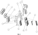
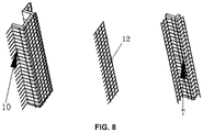
- 1 steel structural beam and column, 2. first composite insulation panel connecting assembly, 3. second composite insulation panel connecting assembly, 4. corner vertical composite insulation panel assembly, 5. composite insulation exterior wall panel, 6. filling insulation layer, 51. composite insulation exterior wall panel I, 52. composite insulation exterior wall panel II, 53. insulation panel, 54. steel wire net, 55. fireproof flame-retardant board, 7. corner type steel wire connecting net, 8. vertical composite insulation panel assembly, 9. horizontal composite insulation panel assembly, 10. omega-shaped steel wire connecting net, 11. steel reinforcing rod, 12. steel wire connecting net, 13. protruded portion, and 14. groove notch portion.
- An objective of the present invention is to provide a structure and method for connecting a composite insulation exterior wall panel and a steel structural beam-column, to solve the problems of the above prior art.
- An inside and an outside of a steel structural body are connected to an insulation layer to implement flexible connection and prevent a junction from cracking; and composite insulation exterior wall panels are connected via a staggered seam to eliminate a continuous seam and improve the insulation effect.
- this embodiment provides a composite insulation exterior wall panel 5 and steel structural beam-column connecting structure, which includes a steel structural beam and a steel structural column; the steel structural beam and the steel structural column respectively include a steel structural body; a filling insulation layer 6 is provided at a gap of the steel structural body; when the steel structural beam and the steel structural column are connected in a cross-shaped structure, a first composite insulation panel connecting assembly 2 is wrapped at a junction between the steel structural beam and the steel structural column; and when the steel structural beam and the steel structural column are in L-shaped connection (connection at a corner), a second composite insulation panel connecting assembly 3 is wrapped at a junction between the steel structural beam and the steel structural column.
- the first composite insulation panel connecting assembly 2 and the second composite insulation panel connecting assembly 3 are respectively connected to a horizontal composite insulation panel assembly 9, via a staggered seam, in a horizontal direction, for wrapping the steel structural beam.
- the first composite insulation panel connecting assembly 2 and the second composite insulation panel connecting assembly 3 are respectively connected to a vertical insulation panel assembly, via a staggered seam, in a vertical direction, for wrapping the steel structural column.
- the number of the horizontal composite insulation panel assemblies and the vertical composite insulation panel assemblies 8 may be selected according to a specific dimension of a wall.
- Multiple composite insulation exterior wall panels 5 are connected between the first composite insulation panel connecting assembly 2, the second composite insulation panel connecting assembly 3 and the horizontal insulation panel assembly, and the vertical insulation panel assembly via a convex-concave staggered seam to form a whole without a continuous seam.
- the composite insulation panel connecting assembly 2, the second composite insulation panel connecting assembly 3, the horizontal composite insulation panel assembly 9, the vertical composite insulation panel assembly 8 and the composite insulation exterior wall panel 5 respectively include an insulation panel body.
- a thickness of each insulation panel body is the same, thereby guaranteeing that the flat composite insulation exterior wall panel 5 can be formed.
- the composite insulation panel body includes an insulation panel 53, a fireproof flame-retardant board 55 and a steel wire net 54; a layer of the fireproof flame-retardant board 55 is respectively disposed on two sides of the insulation panel; a layer of the steel wire net 54 is respectively disposed outside the fireproof flame-retardant boards 55 on the two sides; and a backing strip is further disposed between the steel wire net 54 and the fireproof flame-retardant board 55 to keep a certain distance therebetween.
- the insulation panel layer uses a polystyrene board, a polyurethane board, a graphite polystyrene board or an extruded sheet, etc.
- the fireproof flame-retardant board 55 uses a perlite board and the like, and preferably uses an expanded perlite board. Thicknesses of the insulation panel and the fireproof flame-retardant board 55 may be selected as required, and may be 10-30 cm and 2-5 cm respectively.
- the steel wire net 54 is fixed outside the fireproof flame-retardant board 55 via a web wire strip.
- One end of the web wire strip is welded with the steel wire net 54, and the other end of the web wire strip passes through the fireproof flame-retardant board 55 and is stretched into the insulation panel but not inserted through the insulation panel.
- a steel wire of the steel wire net 54 and the web wire strip all are a zinc-wrapped steel wire having a diameter of 2-3 mm.
- a non-metallic connecting piece is further disposed in the composite insulation panel body. The non-metallic connecting piece is penetrated through the composite insulation panel body. Two ends of the non-metallic connecting piece are respectively and fixedly connected to the steel wire nets 54 on the two sides. With the non-metallic connecting piece, the overall strength of the composite insulated wall board is further improved.
- One side, close to the junction between the steel structural beam and the steel structural column, of the insulation panel body of each of the first composite insulation panel connecting assembly 2 and the second composite insulation panel connecting assembly 3 is provided with a cross-shaped groove or a T-shaped groove; the junction between the steel structural beam and the steel structural column is mounted in the cross-shaped groove or the T-shaped groove; and the steel structural beam and the steel structural column are protruded out of the cross-shaped groove or the T-shaped groove.
- One side, close to the steel structural beam, of the insulation panel body of the horizontal composite insulation panel assembly 9 is provided with a horizontal groove; one side, close to the steel structural column, of the insulation panel body of the vertical insulation panel assembly is provided with a vertical groove; and the steel structural beam and the steel structural columns are respectively disposed in the horizontal groove and the vertical groove, and are protruded out of the horizontal groove and the vertical groove.
- the cross-shaped groove, the T-shaped groove, the horizontal groove and the vertical grooves are located on a same side. With the cooperation of the multiple grooves, the insulation panel completely wraps the steel structural column and the steel structural beam to guarantee the insulation effect.
- a cross-sectional shape of the cross-shaped groove, the T-shaped groove, the horizontal groove and the vertical groove may be selected according to a shape of the steel structural beam and the steel structural column.
- the steel structural beam and the steel structural column are of a cuboid structure respectively, and each groove is also of a matched cuboid structure.
- the fireproof flame-retardant board is further fixed on a front side and a lateral side of a protruded portion of each of the steel structural beam and the steel structural column via an omega-shaped steel wire connecting net 10 or a corner type steel wire connecting net 7.
- the omega-shaped steel wire connecting net 10 or the corner type steel wire connecting net 7 is located outside the fireproof flame-retardant board, with two sides respectively connected to the adjacent steel wire net 54.
- Multiple steel reinforcing rods 11 are further respectively welded on two sides of a steel structural body of the protruded portion of each of the steel structural beam and the steel structural column. Certain ends, far away from the steel structural body, of the steel reinforcing rods 11 are connected to the adjacent steel wire net 54. With the further fixation of the steel reinforcing rods 11, the connecting effect is improved.
- an adjacent junction between the first composite insulation panel connecting assembly 2, the second composite insulation panel connecting assembly 3, the horizontal composite insulation panel assembly 9, the vertical composite insulation panel assembly 8 and the composite insulation exterior wall panel 5 is connected via a staggered seam;
- the staggered seam connection includes a protruded portion 13 or a groove notch portion 14; and a thickness of the protruded portion 13 or the groove notch portion 14 is 2-10 cm, and preferably is 3 cm.
- a connecting method for the structure for connecting a composite insulation exterior wall panel and a steel structural beam-column includes the following steps when a composite insulation panel assembly, a connecting assembly and a composite insulation panel body produced in a factory are transported to a construction site for fabricated assembly:
Landscapes
- Engineering & Computer Science (AREA)
- Architecture (AREA)
- Physics & Mathematics (AREA)
- Civil Engineering (AREA)
- Structural Engineering (AREA)
- Electromagnetism (AREA)
- Acoustics & Sound (AREA)
- Building Environments (AREA)
- Rod-Shaped Construction Members (AREA)
Abstract
Description
- The present invention relates to the technical field of integration of steel structure and wall insulation, and in particular to a structure and method for connecting a composite insulation exterior wall panel and a steel structural beam-column.
- Along with continuous improvement of a building energy-saving standard and continuous development of a building industry in China, in recent years, relevant enterprises have made many beneficial attempts in aspects of prefabricated building, and integration of building structure and insulation, and researched a series of external wall insulation panels. However, the existing external wall insulation panel generally cannot achieve a very good insulation effect, and cannot realize wall insulated integration. Particularly, an external wall board assorted with a steel structure generally has a poor insulation performance. Moreover, due to large deformation of the steel structure, a junction between a board material and a structural main body is cracked easily. In order to solve the above technical problems, there is an urgent need to provide a structure and method for connecting a composite insulation exterior wall panel and a steel structural beam-column, to implement flexible connection between a composite insulation exterior wall panel and a steel structure, and simultaneously improve the insulation performance of a wall.
- An objective of the present invention is to provide a structure and method for connecting a composite insulation exterior wall panel and a steel structural beam-column, to solve the problems of the above prior art. An inside and an outside of a steel structural body are connected to an insulation panel to implement flexible connection; and composite insulation exterior wall panels are connected via a convex-concave staggered seam to prevent a continuous seam and improve the insulation effect.
- To achieve the above purpose, the present invention provides the following technical solutions: The present invention provides a structure for connecting a composite insulation exterior wall panel and a steel structural beam-column, including a steel structural beam and a steel structural column, where the steel structural beam and the steel structural column respectively include a steel structural body; a filling insulation layer is provided at a gap of the steel structural body; when the steel structural beam and the steel structural column are in cross-shaped connection, a first composite insulation panel connecting assembly is wrapped at a junction between the steel structural beam and the steel structural column; when the steel structural beam and the steel structural column are in L-shaped connection for corner connection, a second composite insulation panel connecting assembly is wrapped at a junction between the steel structural beam and the steel structural column; the first composite insulation panel connecting assembly and the second composite insulation panel connecting assembly are respectively connected to a horizontal composite insulation panel assembly, via a staggered seam, in a horizontal direction, for wrapping the steel structural beam; the first composite insulation panel connecting assembly and the second composite insulation panel connecting assembly are respectively connected to a vertical insulation panel assembly, via a staggered seam, in a vertical direction, for wrapping the steel structural column; and the horizontal composite insulation panel assembly and the vertical composite insulation panel assembly are connected to a composite insulation exterior wall panel via a staggered seam to form a composite insulation exterior wall panel whole without a continuous seam.
- Preferably, the first composite insulation panel connecting assembly, the second composite insulation panel connecting assembly, the horizontal composite insulation panel assembly, the vertical composite insulation panel assembly and the composite insulation exterior wall panel respectively includes a composite insulation panel body; the composite insulation panel body includes an insulation panel, a fireproof flame-retardant board and a steel wire net; a layer of the fireproof flame-retardant board is respectively disposed on two sides of the insulation panel; and a layer of the steel wire net is respectively disposed outside the fireproof flame-retardant boards on the two sides.
- Preferably, the steel wire net is fixed outside the fireproof flame-retardant board via a web wire strip; one end of the web wire strip is welded with the steel wire net, and the other end of the web wire strip passes through the fireproof flame-retardant board and is stretched into the insulation panel but not inserted through the insulation panel.
- Preferably, a non-metallic connecting piece is further disposed in the composite insulation panel body; the non-metallic connecting piece is penetrated through the composite insulation panel body; and two ends of the non-metallic connecting piece are respectively and fixedly connected to the steel wire nets on the two sides.
- Preferably, one side, close to the junction between the steel structural beam and the steel structural column, of the insulation panel body of the first composite insulation panel connecting assembly is provided with a cross-shaped groove, the junction between the steel structural beam and the steel structural column is mounted in the cross-shaped groove, and the steel structural beam and the steel structural column are protruded out of the cross-shaped groove; and one side, close to the junction between the steel structural beam and the steel structural column, of the insulation panel body of the second composite insulation panel connecting assembly is provided with a T-shaped groove, the junction between the steel structural beam and the steel structural column is mounted in the T-shaped groove, and the steel structural beam and the steel structural column are protruded out of the T-shaped groove;
one side, close to the steel structural beam, of the insulation panel body of the horizontal composite insulation panel assembly is provided with a horizontal groove; one side, close to the steel structural column, of the insulation panel body of the vertical composite insulation panel assembly is provided with a vertical groove; and the steel structural beam and the steel structural columns are respectively disposed in the horizontal groove and the vertical groove, and are protruded out of the horizontal groove and the vertical groove; and
the cross-shaped groove, the T-shaped groove, the horizontal groove and the vertical grooves are located on a same side. - Preferably, the fireproof flame-retardant board is further fixed on a front side and a lateral side of a protruded portion of each of the steel structural beam and the steel structural column via a steel wire connecting net; and two sides of the steel wire connecting net are respectively connected a steel wire net outside an adjacent insulation panel body.
- Preferably, multiple steel reinforcing rods are further respectively welded on two sides of a steel structural body of the protruded portion of each of the steel structural beam and the steel structural column; and certain ends, far away from the steel structural body, of the steel reinforcing rods are connected to the adjacent steel wire net.
- Preferably, an adjacent junction between the first composite insulation panel connecting assembly, the second composite insulation panel connecting assembly, the horizontal composite insulation panel assembly, the vertical composite insulation panel assembly and the composite insulation exterior wall panel is connected via a staggered seam; the staggered seam connection includes a protruded portion or a groove notch portion; and a thickness of the protruded portion or the groove notch portion is 2-10 cm.
- Preferably, the insulation panel layer, and the filling insulation layer in the gap of the steel structural body use a polystyrene board, a polyurethane board, a graphite polystyrene board or an extruded sheet, etc.; and the fireproof flame-retardant board uses a perlite board and the like.
- The present invention further provides a method for connecting a composite insulation exterior wall panel and a steel structural beam-column, including the following steps when a composite insulation panel assembly, a connecting assembly and a composite insulation panel body produced in a factory are transported to a construction site for fabricated assembly:
- 1) filling an insulation layer in a gap of a steel structural body;
- 2) connecting a first composite insulation panel connecting assembly and a second composite insulation panel connecting assembly to steel structural beam and column;
- 3) respectively connecting a horizontal composite insulation panel assembly and a vertical composite insulation panel assembly to the steel structural beam and the steel structural column;
- 4) connecting multiple composite insulation exterior wall panels between the horizontal composite insulation panel assembly and the vertical composite insulation panel assembly via a convex-concave staggered seam to form a whole without a continuous seam;
- 5) respectively welding multiple steel reinforcing rods on two sides of a steel structural body of a protruded portion of each of the steel structural beam and the steel structural column and connecting the steel reinforcing rods to a steel wire net;
- 6) fixing a fireproof flame-retardant board on a front side and a lateral side of the protruded portion of each of the steel structural beam and the steel structural column via a steel wire connecting net, where the steel wire connecting net is disposed on an outer layer of the fireproof board, and is connected to a steel wire net outside an adjacent composite insulation panel body;
- 7) placing a steel wire connecting net at a seam of various composite insulation panel assemblies, the connecting assemblies and the composite insulation exterior wall panels; and
- 8) spraying and plastering a cement mortar on a steel wire net outside the composite insulation exterior wall panel to form a composite insulated wall.
- Compared with the prior art, the present invention achieves the following technical effects:
In the present invention, an inside and an outside of a steel structural body are connected to an insulation layer to implement flexible connection and prevent a junction from cracking; and composite insulated wall boards are connected via a staggered seam to eliminate a continuous seam and improve the insulation effect. - To describe the technical solutions in the embodiments of the present invention or in the prior art more clearly, the following briefly describes the accompanying drawings required for describing the embodiments. Apparently, the accompanying drawings in the following description show some embodiments of the present invention, and a person of ordinary skill in the art may still derive other drawings from these accompanying drawings without creative efforts.
- FIG. 1
- is an exploded structural schematic diagram of a structure for connecting a composite insulation exterior wall panel and a steel structural beam-column provided by the present invention.
- FIG. 2
- is a structural schematic diagram of a structure for connecting a composite insulation exterior wall panel and a steel structural beam-column provided by the present invention.
- FIG. 3
- is a structural schematic diagram of a composite insulation panel body provided by the present invention.
- FIG. 4
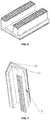
- is a structural schematic diagram of a first composite insulation panel connecting assembly provided by the present invention.
- FIG. 5
- is a structural schematic diagram of a second composite insulation panel connecting assembly provided by the present invention.
- FIG. 6
- is a structural schematic diagram of a horizontal composite insulation panel assembly and a vertical composite insulation panel assembly provided by the present invention.
- FIG. 7
- is a structural schematic diagram of a corner vertical composite insulation panel assembly provided by the present invention.
- FIG. 8
- is a structural schematic diagram of a steel wire connecting net provided by the present invention.
- In the
figure, 1 . steel structural beam and column, 2. first composite insulation panel connecting assembly, 3. second composite insulation panel connecting assembly, 4. corner vertical composite insulation panel assembly, 5. composite insulation exterior wall panel, 6. filling insulation layer, 51. composite insulation exterior wall panel I, 52. composite insulation exterior wall panel II, 53. insulation panel, 54. steel wire net, 55. fireproof flame-retardant board, 7. corner type steel wire connecting net, 8. vertical composite insulation panel assembly, 9. horizontal composite insulation panel assembly, 10. omega-shaped steel wire connecting net, 11. steel reinforcing rod, 12. steel wire connecting net, 13. protruded portion, and 14. groove notch portion. - The following clearly and completely describes the technical solutions in the embodiments of the present invention with reference to the accompanying drawings in the embodiments of the present invention. Apparently, the described embodiments are merely a part rather than all of the embodiments of the present invention. All other embodiments obtained by a person of ordinary skill in the art based on the embodiments of the present invention without creative efforts shall fall within the protection scope of the present invention.
- An objective of the present invention is to provide a structure and method for connecting a composite insulation exterior wall panel and a steel structural beam-column, to solve the problems of the above prior art. An inside and an outside of a steel structural body are connected to an insulation layer to implement flexible connection and prevent a junction from cracking; and composite insulation exterior wall panels are connected via a staggered seam to eliminate a continuous seam and improve the insulation effect.
- To make the foregoing objective, features, and advantages of the present invention clearer and more comprehensible, the present invention is further described in detail below with reference to the accompanying drawings and specific embodiments.
- As shown in
FIGs. 1-8 , this embodiment provides a composite insulationexterior wall panel 5 and steel structural beam-column connecting structure, which includes a steel structural beam and a steel structural column; the steel structural beam and the steel structural column respectively include a steel structural body; a filling insulation layer 6 is provided at a gap of the steel structural body; when the steel structural beam and the steel structural column are connected in a cross-shaped structure, a first composite insulationpanel connecting assembly 2 is wrapped at a junction between the steel structural beam and the steel structural column; and when the steel structural beam and the steel structural column are in L-shaped connection (connection at a corner), a second composite insulationpanel connecting assembly 3 is wrapped at a junction between the steel structural beam and the steel structural column. - The first composite insulation
panel connecting assembly 2 and the second composite insulationpanel connecting assembly 3 are respectively connected to a horizontal composite insulation panel assembly 9, via a staggered seam, in a horizontal direction, for wrapping the steel structural beam. The first composite insulationpanel connecting assembly 2 and the second composite insulationpanel connecting assembly 3 are respectively connected to a vertical insulation panel assembly, via a staggered seam, in a vertical direction, for wrapping the steel structural column. The number of the horizontal composite insulation panel assemblies and the vertical compositeinsulation panel assemblies 8 may be selected according to a specific dimension of a wall. Multiple composite insulationexterior wall panels 5 are connected between the first composite insulationpanel connecting assembly 2, the second composite insulationpanel connecting assembly 3 and the horizontal insulation panel assembly, and the vertical insulation panel assembly via a convex-concave staggered seam to form a whole without a continuous seam. - Specifically, in this embodiment, the composite insulation
panel connecting assembly 2, the second composite insulationpanel connecting assembly 3, the horizontal composite insulation panel assembly 9, the vertical compositeinsulation panel assembly 8 and the composite insulationexterior wall panel 5 respectively include an insulation panel body. A thickness of each insulation panel body is the same, thereby guaranteeing that the flat composite insulationexterior wall panel 5 can be formed. The composite insulation panel body includes aninsulation panel 53, a fireproof flame-retardant board 55 and asteel wire net 54; a layer of the fireproof flame-retardant board 55 is respectively disposed on two sides of the insulation panel; a layer of thesteel wire net 54 is respectively disposed outside the fireproof flame-retardant boards 55 on the two sides; and a backing strip is further disposed between thesteel wire net 54 and the fireproof flame-retardant board 55 to keep a certain distance therebetween. The insulation panel layer uses a polystyrene board, a polyurethane board, a graphite polystyrene board or an extruded sheet, etc. The fireproof flame-retardant board 55 uses a perlite board and the like, and preferably uses an expanded perlite board. Thicknesses of the insulation panel and the fireproof flame-retardant board 55 may be selected as required, and may be 10-30 cm and 2-5 cm respectively. - The
steel wire net 54 is fixed outside the fireproof flame-retardant board 55 via a web wire strip. One end of the web wire strip is welded with thesteel wire net 54, and the other end of the web wire strip passes through the fireproof flame-retardant board 55 and is stretched into the insulation panel but not inserted through the insulation panel. A steel wire of thesteel wire net 54 and the web wire strip all are a zinc-wrapped steel wire having a diameter of 2-3 mm. A non-metallic connecting piece is further disposed in the composite insulation panel body. The non-metallic connecting piece is penetrated through the composite insulation panel body. Two ends of the non-metallic connecting piece are respectively and fixedly connected to the steel wire nets 54 on the two sides. With the non-metallic connecting piece, the overall strength of the composite insulated wall board is further improved. - One side, close to the junction between the steel structural beam and the steel structural column, of the insulation panel body of each of the first composite insulation
panel connecting assembly 2 and the second composite insulationpanel connecting assembly 3 is provided with a cross-shaped groove or a T-shaped groove; the junction between the steel structural beam and the steel structural column is mounted in the cross-shaped groove or the T-shaped groove; and the steel structural beam and the steel structural column are protruded out of the cross-shaped groove or the T-shaped groove. One side, close to the steel structural beam, of the insulation panel body of the horizontal composite insulation panel assembly 9 is provided with a horizontal groove; one side, close to the steel structural column, of the insulation panel body of the vertical insulation panel assembly is provided with a vertical groove; and the steel structural beam and the steel structural columns are respectively disposed in the horizontal groove and the vertical groove, and are protruded out of the horizontal groove and the vertical groove. The cross-shaped groove, the T-shaped groove, the horizontal groove and the vertical grooves are located on a same side. With the cooperation of the multiple grooves, the insulation panel completely wraps the steel structural column and the steel structural beam to guarantee the insulation effect. - Specifically, a cross-sectional shape of the cross-shaped groove, the T-shaped groove, the horizontal groove and the vertical groove may be selected according to a shape of the steel structural beam and the steel structural column. In this embodiment, the steel structural beam and the steel structural column are of a cuboid structure respectively, and each groove is also of a matched cuboid structure.
- Further, the fireproof flame-retardant board is further fixed on a front side and a lateral side of a protruded portion of each of the steel structural beam and the steel structural column via an omega-shaped steel
wire connecting net 10 or a corner type steel wire connecting net 7. The omega-shaped steelwire connecting net 10 or the corner type steel wire connecting net 7 is located outside the fireproof flame-retardant board, with two sides respectively connected to the adjacentsteel wire net 54. Multiplesteel reinforcing rods 11 are further respectively welded on two sides of a steel structural body of the protruded portion of each of the steel structural beam and the steel structural column. Certain ends, far away from the steel structural body, of thesteel reinforcing rods 11 are connected to the adjacentsteel wire net 54. With the further fixation of thesteel reinforcing rods 11, the connecting effect is improved. - In this embodiment, an adjacent junction between the first composite insulation
panel connecting assembly 2, the second composite insulationpanel connecting assembly 3, the horizontal composite insulation panel assembly 9, the vertical compositeinsulation panel assembly 8 and the composite insulationexterior wall panel 5 is connected via a staggered seam; the staggered seam connection includes a protrudedportion 13 or agroove notch portion 14; and a thickness of the protrudedportion 13 or thegroove notch portion 14 is 2-10 cm, and preferably is 3 cm. With the connection via the staggered seam, a continuous seam is eliminated to reduce the heat loss and improve the insulation effect. A specific position of the protrudedportion 13 or thegroove notch portion 14 may be selected as required provided that the continuous seam can be eliminated. - In this embodiment, a connecting method for the structure for connecting a composite insulation exterior wall panel and a steel structural beam-column includes the following steps when a composite insulation panel assembly, a connecting assembly and a composite insulation panel body produced in a factory are transported to a construction site for fabricated assembly:
- 1) Fill an insulation layer in a gap of a steel structural body.
- 2) Connect a first composite insulation panel connecting assembly and a second composite insulation panel connecting assembly to steel structural beam and column.
- 3) Respectively connect a horizontal composite insulation panel assembly and a vertical composite insulation panel assembly to the steel structural beam and the steel structural column.
- 4) Connecting multiple composite insulation exterior wall panels between the horizontal composite insulation panel assembly and the vertical composite insulation panel assembly via a convex-concave staggered seam to form a whole without a continuous seam.
- 5) Respectively weld multiple steel reinforcing rods on two sides of a steel structural body of a protruded portion of each of the steel structural beam and the steel structural column and connect the steel reinforcing rods to a steel wire net.
- 6) Fix a fireproof flame-retardant board on a front side and a lateral side of the protruded portion of each of the steel structural beam and the steel structural column via an omega-shaped steel
wire connecting net 10 or a corner type steel wire connecting net 7, where the steel wire connecting net is disposed on an outer layer of the fireproof board, and is connected to an adjacent steel wire net. - 7) Place a steel
wire connecting net 12 at a seam of the composite insulation panel assembly, the connecting assembly and the composite insulation exterior wall panel. - 8) Spray and plaster a cement mortar on a steel wire net outside the composite insulation exterior wall panel to form a composite insulated wall.
- Several examples are used for illustration of the principles and implementation methods of the present invention. The description of the embodiments is used to help illustrate the method and its core principles of the present invention. In addition, those skilled in the art can make various modifications in terms of specific embodiments and scope of application in accordance with the teachings of the present invention. In conclusion, the content of this specification shall not be construed as a limitation to the invention.
Claims (10)
- A structure for connecting a composite insulation exterior wall panel and a steel structural beam-column, comprising a steel structural beam and a steel structural column, wherein the steel structural beam and the steel structural column respectively comprise a steel structural body; a filling insulation layer is provided at a gap of the steel structural body; when the steel structural beam and the steel structural column are in cross-shaped connection, a first composite insulation panel connecting assembly is wrapped at a junction between the steel structural beam and the steel structural column; when the steel structural beam and the steel structural column are in L-shaped connection for corner connection, a second composite insulation panel connecting assembly is wrapped at a junction between the steel structural beam and the steel structural column; the first composite insulation panel connecting assembly and the second composite insulation panel connecting assembly are respectively connected to a horizontal composite insulation panel assembly, via a staggered seam, in a horizontal direction, for wrapping the steel structural beam; the first composite insulation panel connecting assembly and the second composite insulation panel connecting assembly are respectively connected to a vertical insulation panel assembly, via a staggered seam, in a vertical direction, for wrapping the steel structural column; and the horizontal composite insulation panel assembly and the vertical composite insulation panel assembly are connected to a composite insulation exterior wall panel via a staggered seam to form a composite insulation exterior wall panel whole without a continuous seam.
- The structure for connecting a composite insulation exterior wall panel and a steel structural beam-column according to claim 1, wherein the first composite insulation panel connecting assembly, the second composite insulation panel connecting assembly, the horizontal composite insulation panel assembly, the vertical composite insulation panel assembly and the composite insulation exterior wall panel respectively comprises a composite insulation panel body; the composite insulation panel body comprises an insulation panel, a fireproof flame-retardant board and a steel wire net; a layer of the fireproof flame-retardant board is respectively disposed on two sides of the insulation panel; and a layer of the steel wire net is respectively disposed outside the fireproof flame-retardant boards on the two sides.
- The structure for connecting a composite insulation exterior wall panel and a steel structural beam-column according to claim 2, wherein the steel wire net is fixed outside the fireproof flame-retardant board via a web wire strip; one end of the web wire strip is welded with the steel wire net, and the other end of the web wire strip passes through the fireproof flame-retardant board and is stretched into the insulation panel but not inserted through the insulation panel.
- The structure for connecting a composite insulation exterior wall panel and a steel structural beam-column according to claim 3, wherein a non-metallic connecting piece is further disposed in the composite insulation panel body; the non-metallic connecting piece is penetrated through the composite insulation panel body; and two ends of the non-metallic connecting piece are respectively and fixedly connected to the steel wire nets on the two sides.
- The structure for connecting a composite insulation exterior wall panel and a steel structural beam-column according to claim 2, wherein one side, close to the junction between the steel structural beam and the steel structural column, of the insulation panel body of the first composite insulation panel connecting assembly is provided with a cross-shaped groove, the junction between the steel structural beam and the steel structural column is mounted in the cross-shaped groove, and the steel structural beam and the steel structural column are protruded out of the cross-shaped groove; and one side, close to the junction between the steel structural beam and the steel structural column, of the insulation panel body of the second composite insulation panel connecting assembly is provided with a T-shaped groove, the junction between the steel structural beam and the steel structural column is mounted in the T-shaped groove, and the steel structural beam and the steel structural column are protruded out of the T-shaped groove;
one side, close to the steel structural beam, of the insulation panel body of the horizontal composite insulation panel assembly is provided with a horizontal groove; one side, close to the steel structural column, of the insulation panel body of the vertical composite insulation panel assembly is provided with a vertical groove; and the steel structural beam and the steel structural columns are respectively disposed in the horizontal groove and the vertical groove, and are protruded out of the horizontal groove and the vertical groove; and
the cross-shaped groove, the T-shaped groove, the horizontal groove and the vertical grooves are located on a same side. - The structure for connecting a composite insulation exterior wall panel and a steel structural beam-column according to claim 5, wherein the fireproof flame-retardant board is further fixed on a front side and a lateral side of a protruded portion of each of the steel structural beam and the steel structural column via a steel wire connecting net; and two sides of the steel wire connecting net are respectively connected a steel wire net outside an adjacent insulation panel body.
- The structure for connecting a composite insulation exterior wall panel and a steel structural beam-column according to claim 6, wherein multiple steel reinforcing rods are further respectively welded on two sides of a steel structural body of the protruded portion of each of the steel structural beam and the steel structural column; and certain ends, far away from the steel structural body, of the steel reinforcing rods are connected to the adjacent steel wire net.
- The structure for connecting a composite insulation exterior wall panel and a steel structural beam-column according to any one of claim 7, wherein an adjacent junction between the first composite insulation panel connecting assembly, the second composite insulation panel connecting assembly, the horizontal composite insulation panel assembly, the vertical composite insulation panel assembly and the composite insulation exterior wall panel is connected via a staggered seam; the staggered seam connection comprises a protruded portion or a groove notch portion; and a thickness of the protruded portion or the groove notch portion is 2-10 cm.
- The structure for connecting a composite insulation exterior wall panel and a steel structural beam-column according to any one of claims 2 to 8, wherein the insulation panel layer, and the filling insulation layer in the gap of the steel structural body use a polystyrene board, a polyurethane board, a graphite polystyrene board or an extruded sheet, etc.; and the fireproof flame-retardant board uses a perlite board and the like.
- A method for connecting a composite insulation exterior wall panel and a steel structural beam-column, comprising the following steps when a composite insulation panel assembly, a connecting assembly and a composite insulation panel body produced in a factory are transported to a construction site for fabricated assembly:1) filling an insulation layer in a gap of a steel structural body;2) connecting a first composite insulation panel connecting assembly and a second composite insulation panel connecting assembly to steel structural beam and column;3) respectively connecting a horizontal composite insulation panel assembly and a vertical composite insulation panel assembly to the steel structural beam and the steel structural column;4) connecting multiple composite insulation exterior wall panels between the horizontal composite insulation panel assembly and the vertical composite insulation panel assembly via a convex-concave staggered seam to form a whole without a continuous seam;5) respectively welding multiple steel reinforcing rods on two sides of a steel structural body of a protruded portion of each of the steel structural beam and the steel structural column and connecting the steel reinforcing rods to a steel wire net;6) fixing a fireproof flame-retardant board on a front side and a lateral side of the protruded portion of each of the steel structural beam and the steel structural column via a steel wire connecting net, wherein the steel wire connecting net is disposed on an outer layer of the fireproof board, and is connected to a steel wire net outside an adjacent composite insulation panel body;7) placing a steel wire connecting net at a seam of various composite insulation panel assemblies, the connecting assemblies and the composite insulation exterior wall panels; and8) spraying and plastering a cement mortar on a steel wire net outside the composite insulation exterior wall panel to form a composite insulated wall.
Applications Claiming Priority (1)
| Application Number | Priority Date | Filing Date | Title |
|---|---|---|---|
| CN201811407484.6A CN109267674B (en) | 2018-11-20 | 2018-11-20 | A connection structure and method between composite thermal insulation exterior wall panels and steel structure beams and columns |
Publications (5)
| Publication Number | Publication Date |
|---|---|
| EP3656942A1 true EP3656942A1 (en) | 2020-05-27 |
| EP3656942A8 EP3656942A8 (en) | 2020-08-19 |
| EP3656942B1 EP3656942B1 (en) | 2025-12-03 |
| EP3656942C0 EP3656942C0 (en) | 2025-12-03 |
| EP3656942B9 EP3656942B9 (en) | 2026-03-18 |
Family
ID=65191426
Family Applications (1)
| Application Number | Title | Priority Date | Filing Date |
|---|---|---|---|
| EP19205067.2A Active EP3656942B9 (en) | 2018-11-20 | 2019-10-24 | Composite insulation wall and method for constructing such a wall |
Country Status (4)
| Country | Link |
|---|---|
| US (1) | US11180917B2 (en) |
| EP (1) | EP3656942B9 (en) |
| CN (1) | CN109267674B (en) |
| RU (1) | RU2722386C1 (en) |
Cited By (2)
| Publication number | Priority date | Publication date | Assignee | Title |
|---|---|---|---|---|
| CN111851852A (en) * | 2020-07-28 | 2020-10-30 | 盐城工学院 | A composite wall panel and its connection structure with steel beams |
| EP3786379A1 (en) * | 2019-08-29 | 2021-03-03 | Hebei Huiyuan Building Materials Co., Ltd | Assembled connection structure of roof boards, eave boards, and wallboards and its connection method |
Families Citing this family (3)
| Publication number | Priority date | Publication date | Assignee | Title |
|---|---|---|---|---|
| CN115889937B (en) * | 2023-03-09 | 2023-05-02 | 云南建投钢结构股份有限公司 | Welding construction method for steel structure beam, column and wall encircling combined node member |
| JP7816313B2 (en) * | 2023-08-23 | 2026-02-18 | 村田機械株式会社 | automated warehouse |
| CN117183084B (en) * | 2023-11-07 | 2024-02-27 | 北京建工四建工程建设有限公司 | Manufacturing method of sandwich external wall panel with VIP (VIP) board composite heat insulation layer |
Citations (3)
| Publication number | Priority date | Publication date | Assignee | Title |
|---|---|---|---|---|
| FR2092721A1 (en) * | 1970-06-11 | 1972-01-28 | Assie Jacqueline | |
| US20070101675A1 (en) * | 2005-10-26 | 2007-05-10 | Veerhuis Beheer, B.V. | Method of constructing a building, such building, and wall and floor elements for use therein |
| FR3034792A1 (en) * | 2015-04-10 | 2016-10-14 | Olivier Caron | NEW METHOD OF THERMAL AND PHONIC INSULATION OF METALLIC STRUCTURE BUILDINGS |
Family Cites Families (37)
| Publication number | Priority date | Publication date | Assignee | Title |
|---|---|---|---|---|
| US1858715A (en) * | 1928-08-06 | 1932-05-17 | Stewart R Mckay | Building construction |
| US1997809A (en) * | 1933-04-12 | 1935-04-16 | Cole Harry | Building construction |
| US2027882A (en) * | 1933-12-07 | 1936-01-14 | Rostone Inc | Building construction |
| US2193550A (en) * | 1937-04-01 | 1940-03-12 | Jr Thomas H Coe | Prefabricated building |
| US2160225A (en) * | 1938-05-23 | 1939-05-30 | James H Hammon | Building construction |
| US2366108A (en) * | 1941-10-22 | 1944-12-26 | Hitchins William George | Construction of buildings |
| US2970676A (en) * | 1958-01-27 | 1961-02-07 | Olin Mathieson | Framework construction |
| GB1253033A (en) * | 1968-01-23 | 1971-11-10 | ||
| US4320604A (en) * | 1978-12-20 | 1982-03-23 | Hanlon Edward J O | Heavily insulated shelter structure |
| US4342177A (en) * | 1979-06-18 | 1982-08-03 | Smith Donald A | Prefabricated steel frame building construction components and methods |
| SU876900A1 (en) * | 1980-01-10 | 1981-10-30 | Государственный Проектный И Научно-Исследовательский Институт Челябинский Промстройниипроект | Butt joint of three-layer panels and framework of building |
| US4573292A (en) * | 1982-07-13 | 1986-03-04 | Restroom Facilities Corporation | Prefabricated, self-contained building |
| SU1323678A1 (en) * | 1985-07-15 | 1987-07-15 | И. Ю. Семенцова | Enclosing structure |
| IT1266784B1 (en) * | 1993-11-09 | 1997-01-21 | Dlc Srl | INDUSTRIAL PREFABRICATED FLOOR |
| US5782047A (en) * | 1996-07-19 | 1998-07-21 | De Quesada; Jorge | High-rise building system using light gauge steel wall panels |
| AUPR062700A0 (en) * | 2000-10-10 | 2000-11-02 | Davison, Mark | Prefabricated modular building system |
| JP3621048B2 (en) * | 2001-02-01 | 2005-02-16 | 株式会社テスク | Reinforced concrete exterior insulation building |
| US6625943B1 (en) * | 2001-02-27 | 2003-09-30 | Peter S. Renner | Building interior construction system and method |
| US20100162659A1 (en) * | 2007-03-28 | 2010-07-01 | Maisons Laprise Inc. | Insulated Structural Wall Panel |
| KR100784494B1 (en) * | 2007-10-05 | 2007-12-11 | (주) 한국스치로폴 | Lightweight insulating blocks for construction |
| CN101509283A (en) * | 2009-03-19 | 2009-08-19 | 吴淑环 | External thermal insulation composite wall of exterior wall with support |
| CN101736832B (en) * | 2009-12-18 | 2011-08-10 | 北京工业大学 | Confined masonry structure and making method thereof |
| GB2481126B (en) * | 2010-06-08 | 2016-05-18 | Kingspan Res And Dev Ltd | A structural infill wall panel module |
| RU104949U1 (en) * | 2011-01-12 | 2011-05-27 | Открытое акционерное общество "Сибирский энергетический научно-технический центр" | EXTERNAL HEATING SYSTEM FOR HEATING POWER PLANTS (OPTIONS) |
| US8959867B2 (en) * | 2011-03-16 | 2015-02-24 | John A. Schold | Systems and methods for constructing a building structure |
| US9745739B2 (en) * | 2014-02-25 | 2017-08-29 | Breton Systems Llc | Wall construction method using injected urethane foam between the wall and autoclaved concrete (AAC) blocks |
| CN104264861A (en) * | 2014-09-02 | 2015-01-07 | 绿建科技集团新型建材高技术有限公司 | Wall insulation system built of compound insulation building blocks |
| CN104251026A (en) * | 2014-09-02 | 2014-12-31 | 绿建科技集团新型建材高技术有限公司 | Inorganic fireproof self-heat-insulation system with fully externally enclosed and built cast-in-situ walls |
| US9574341B2 (en) * | 2014-09-09 | 2017-02-21 | Romeo Ilarian Ciuperca | Insulated reinforced foam sheathing, reinforced elastomeric vapor permeable air barrier foam panel and method of making and using same |
| EA028597B1 (en) * | 2014-12-17 | 2017-12-29 | Геннадий Александрович Мордич | External wall of multistory frame building of arkos-dsc system and method of its erection |
| US9695608B2 (en) * | 2015-07-01 | 2017-07-04 | District Homes, LLC | Reconfigurable residential unit |
| CN205776830U (en) * | 2016-01-25 | 2016-12-07 | 深圳市摩天氟碳科技有限公司 | A kind of compound heat-insulation board of outer wall and wall mounting structure |
| CN207003665U (en) * | 2017-03-30 | 2018-02-13 | 浙江达攀环保科技有限公司 | Steel construction assembled architecture outer wall board connecting structure |
| US10724228B2 (en) * | 2017-05-12 | 2020-07-28 | Innovative Building Technologies, Llc | Building assemblies and methods for constructing a building using pre-assembled floor-ceiling panels and walls |
| CN106968362B (en) * | 2017-05-12 | 2023-06-16 | 保定市冀创建筑工程有限公司 | Steel wire net rack composite heat-insulating sandwich wallboard node and construction method thereof |
| CN108118798A (en) * | 2017-12-01 | 2018-06-05 | 北京建筑大学 | A kind of assembled air entrained concrete building systems |
| CN209227826U (en) * | 2018-11-20 | 2019-08-09 | 河北卉原建材有限公司 | A kind of composite thermal-insulation external wall panel and beam column of steel structure connection structure |
-
2018
- 2018-11-20 CN CN201811407484.6A patent/CN109267674B/en active Active
-
2019
- 2019-10-24 EP EP19205067.2A patent/EP3656942B9/en active Active
- 2019-11-18 RU RU2019136921A patent/RU2722386C1/en active
- 2019-11-19 US US16/688,206 patent/US11180917B2/en active Active
Patent Citations (3)
| Publication number | Priority date | Publication date | Assignee | Title |
|---|---|---|---|---|
| FR2092721A1 (en) * | 1970-06-11 | 1972-01-28 | Assie Jacqueline | |
| US20070101675A1 (en) * | 2005-10-26 | 2007-05-10 | Veerhuis Beheer, B.V. | Method of constructing a building, such building, and wall and floor elements for use therein |
| FR3034792A1 (en) * | 2015-04-10 | 2016-10-14 | Olivier Caron | NEW METHOD OF THERMAL AND PHONIC INSULATION OF METALLIC STRUCTURE BUILDINGS |
Cited By (2)
| Publication number | Priority date | Publication date | Assignee | Title |
|---|---|---|---|---|
| EP3786379A1 (en) * | 2019-08-29 | 2021-03-03 | Hebei Huiyuan Building Materials Co., Ltd | Assembled connection structure of roof boards, eave boards, and wallboards and its connection method |
| CN111851852A (en) * | 2020-07-28 | 2020-10-30 | 盐城工学院 | A composite wall panel and its connection structure with steel beams |
Also Published As
| Publication number | Publication date |
|---|---|
| RU2722386C1 (en) | 2020-05-29 |
| CN109267674A (en) | 2019-01-25 |
| US11180917B2 (en) | 2021-11-23 |
| EP3656942A8 (en) | 2020-08-19 |
| CN109267674B (en) | 2023-12-12 |
| US20200157813A1 (en) | 2020-05-21 |
| EP3656942B1 (en) | 2025-12-03 |
| EP3656942B9 (en) | 2026-03-18 |
| EP3656942C0 (en) | 2025-12-03 |
Similar Documents
| Publication | Publication Date | Title |
|---|---|---|
| US11180917B2 (en) | Structure and method for connecting a composite insulation exterior wall panel and a steel structural beam-column | |
| CN103437463B (en) | Prefabricated light steel fireproof load-bearing combined wall structure | |
| CN111561074A (en) | A kind of lightweight ultra-high sound insulation fireproof steel partition wall and construction method thereof | |
| CN110158853A (en) | A kind of prefabricated sandwich heat preservation wallboard | |
| CN106968362B (en) | Steel wire net rack composite heat-insulating sandwich wallboard node and construction method thereof | |
| CN211690917U (en) | Prefabricated double-sided heat preservation superimposed shear wall | |
| CN212926687U (en) | Bamboo and concrete wall panels | |
| JP6178072B2 (en) | Drywall structure | |
| CN206495409U (en) | A kind of fireproof heat insulating Acoustic barrier plate | |
| CN211899232U (en) | Prestressed steel pipe truss external wall panel and wall body manufactured and installed using the same | |
| CN104805928A (en) | Pump watering core material fibreboard wrapping sandwich insulation outer wall | |
| CN209227826U (en) | A kind of composite thermal-insulation external wall panel and beam column of steel structure connection structure | |
| CN210049403U (en) | Frame and shear wall core tube combined assembly type structure system | |
| CN217461037U (en) | Multi-layer ultralow-energy-consumption modularized integrated wallboard and wall | |
| KR20200083091A (en) | Insulation panel for constructure and production method for this same | |
| CN210947350U (en) | Roof boarding, eaves board, wallboard assembled connection structure | |
| CN105019581A (en) | Partition wall structure and installation method thereof | |
| CN212336510U (en) | External wall panel component and frame structure building system comprising same | |
| CN213233777U (en) | Continuous heat preservation type node device for prefabricated air conditioner plate | |
| CN214006122U (en) | A prefabricated inner partition wall | |
| CN211472979U (en) | Net rack superposed wall structure with reinforced frame | |
| EP2739800A1 (en) | Multi-layer component | |
| CN212926685U (en) | Bamboo and concrete wall panels | |
| CN209958608U (en) | A new type of combined wall panel | |
| CN109944337B (en) | Frame and shear wall combined assembled structural system |
Legal Events
| Date | Code | Title | Description |
|---|---|---|---|
| PUAI | Public reference made under article 153(3) epc to a published international application that has entered the european phase |
Free format text: ORIGINAL CODE: 0009012 |
|
| STAA | Information on the status of an ep patent application or granted ep patent |
Free format text: STATUS: REQUEST FOR EXAMINATION WAS MADE |
|
| 17P | Request for examination filed |
Effective date: 20191024 |
|
| AK | Designated contracting states |
Kind code of ref document: A1 Designated state(s): AL AT BE BG CH CY CZ DE DK EE ES FI FR GB GR HR HU IE IS IT LI LT LU LV MC MK MT NL NO PL PT RO RS SE SI SK SM TR |
|
| AX | Request for extension of the european patent |
Extension state: BA ME |
|
| RBV | Designated contracting states (corrected) |
Designated state(s): AL AT BE BG CH CY CZ DE DK EE ES FI FR GB GR HR HU IE IS IT LI LT LU LV MC MK MT NL NO PL PT RO RS SE SI SK SM TR |
|
| STAA | Information on the status of an ep patent application or granted ep patent |
Free format text: STATUS: EXAMINATION IS IN PROGRESS |
|
| 17Q | First examination report despatched |
Effective date: 20230111 |
|
| GRAP | Despatch of communication of intention to grant a patent |
Free format text: ORIGINAL CODE: EPIDOSNIGR1 |
|
| STAA | Information on the status of an ep patent application or granted ep patent |
Free format text: STATUS: GRANT OF PATENT IS INTENDED |
|
| RIC1 | Information provided on ipc code assigned before grant |
Ipc: E04B 1/94 20060101AFI20250821BHEP Ipc: E04B 1/76 20060101ALI20250821BHEP Ipc: E04B 1/80 20060101ALN20250821BHEP |
|
| GRAS | Grant fee paid |
Free format text: ORIGINAL CODE: EPIDOSNIGR3 |
|
| INTG | Intention to grant announced |
Effective date: 20250901 |
|
| GRAA | (expected) grant |
Free format text: ORIGINAL CODE: 0009210 |
|
| STAA | Information on the status of an ep patent application or granted ep patent |
Free format text: STATUS: THE PATENT HAS BEEN GRANTED |
|
| AK | Designated contracting states |
Kind code of ref document: B1 Designated state(s): AL AT BE BG CH CY CZ DE DK EE ES FI FR GB GR HR HU IE IS IT LI LT LU LV MC MK MT NL NO PL PT RO RS SE SI SK SM TR |
|
| REG | Reference to a national code |
Ref country code: CH Ref legal event code: F10 Free format text: ST27 STATUS EVENT CODE: U-0-0-F10-F00 (AS PROVIDED BY THE NATIONAL OFFICE) Effective date: 20251203 Ref country code: GB Ref legal event code: FG4D |
|
| REG | Reference to a national code |
Ref country code: IE Ref legal event code: FG4D |
|
| U01 | Request for unitary effect filed |
Effective date: 20251205 |
|
| U07 | Unitary effect registered |
Designated state(s): AT BE BG DE DK EE FI FR IT LT LU LV MT NL PT RO SE SI Effective date: 20251212 |
|
| REG | Reference to a national code |
Ref country code: CH Ref legal event code: Q17 Free format text: ST27 STATUS EVENT CODE: U-0-0-Q10-Q17 (AS PROVIDED BY THE NATIONAL OFFICE) Effective date: 20260218 |
|
| PG25 | Lapsed in a contracting state [announced via postgrant information from national office to epo] |
Ref country code: ES Free format text: LAPSE BECAUSE OF FAILURE TO SUBMIT A TRANSLATION OF THE DESCRIPTION OR TO PAY THE FEE WITHIN THE PRESCRIBED TIME-LIMIT Effective date: 20251203 |
|
| PG25 | Lapsed in a contracting state [announced via postgrant information from national office to epo] |
Ref country code: NO Free format text: LAPSE BECAUSE OF FAILURE TO SUBMIT A TRANSLATION OF THE DESCRIPTION OR TO PAY THE FEE WITHIN THE PRESCRIBED TIME-LIMIT Effective date: 20260303 |
|
| PG25 | Lapsed in a contracting state [announced via postgrant information from national office to epo] |
Ref country code: HR Free format text: LAPSE BECAUSE OF FAILURE TO SUBMIT A TRANSLATION OF THE DESCRIPTION OR TO PAY THE FEE WITHIN THE PRESCRIBED TIME-LIMIT Effective date: 20251203 |
|
| PG25 | Lapsed in a contracting state [announced via postgrant information from national office to epo] |
Ref country code: RS Free format text: LAPSE BECAUSE OF FAILURE TO SUBMIT A TRANSLATION OF THE DESCRIPTION OR TO PAY THE FEE WITHIN THE PRESCRIBED TIME-LIMIT Effective date: 20260303 |
|
| PG25 | Lapsed in a contracting state [announced via postgrant information from national office to epo] |
Ref country code: PL Free format text: LAPSE BECAUSE OF FAILURE TO SUBMIT A TRANSLATION OF THE DESCRIPTION OR TO PAY THE FEE WITHIN THE PRESCRIBED TIME-LIMIT Effective date: 20251203 |
|
| PG25 | Lapsed in a contracting state [announced via postgrant information from national office to epo] |
Ref country code: SM Free format text: LAPSE BECAUSE OF FAILURE TO SUBMIT A TRANSLATION OF THE DESCRIPTION OR TO PAY THE FEE WITHIN THE PRESCRIBED TIME-LIMIT Effective date: 20251203 |
|
| PG25 | Lapsed in a contracting state [announced via postgrant information from national office to epo] |
Ref country code: IS Free format text: LAPSE BECAUSE OF FAILURE TO SUBMIT A TRANSLATION OF THE DESCRIPTION OR TO PAY THE FEE WITHIN THE PRESCRIBED TIME-LIMIT Effective date: 20260403 |
|
| PG25 | Lapsed in a contracting state [announced via postgrant information from national office to epo] |
Ref country code: CZ Free format text: LAPSE BECAUSE OF FAILURE TO SUBMIT A TRANSLATION OF THE DESCRIPTION OR TO PAY THE FEE WITHIN THE PRESCRIBED TIME-LIMIT Effective date: 20251203 |
|
| PG25 | Lapsed in a contracting state [announced via postgrant information from national office to epo] |
Ref country code: SK Free format text: LAPSE BECAUSE OF FAILURE TO SUBMIT A TRANSLATION OF THE DESCRIPTION OR TO PAY THE FEE WITHIN THE PRESCRIBED TIME-LIMIT Effective date: 20251203 |