EP3656933B1 - Work machine and system including work machine - Google Patents
Work machine and system including work machine Download PDFInfo
- Publication number
- EP3656933B1 EP3656933B1 EP19771632.7A EP19771632A EP3656933B1 EP 3656933 B1 EP3656933 B1 EP 3656933B1 EP 19771632 A EP19771632 A EP 19771632A EP 3656933 B1 EP3656933 B1 EP 3656933B1
- Authority
- EP
- European Patent Office
- Prior art keywords
- work
- works
- contents
- bucket
- excavation
- Prior art date
- Legal status (The legal status is an assumption and is not a legal conclusion. Google has not performed a legal analysis and makes no representation as to the accuracy of the status listed.)
- Active
Links
- 238000009412 basement excavation Methods 0.000 claims description 149
- 238000001514 detection method Methods 0.000 claims description 46
- 238000005520 cutting process Methods 0.000 description 63
- 230000007935 neutral effect Effects 0.000 description 17
- 239000000446 fuel Substances 0.000 description 16
- 238000010586 diagram Methods 0.000 description 14
- 238000000034 method Methods 0.000 description 13
- 239000002689 soil Substances 0.000 description 13
- 238000000605 extraction Methods 0.000 description 11
- 230000008859 change Effects 0.000 description 10
- 230000008569 process Effects 0.000 description 9
- 230000006870 function Effects 0.000 description 8
- 230000007246 mechanism Effects 0.000 description 8
- 230000005540 biological transmission Effects 0.000 description 7
- 239000010720 hydraulic oil Substances 0.000 description 6
- 238000012545 processing Methods 0.000 description 6
- 238000011156 evaluation Methods 0.000 description 4
- 239000003921 oil Substances 0.000 description 4
- 238000012549 training Methods 0.000 description 4
- 238000004891 communication Methods 0.000 description 3
- 230000001186 cumulative effect Effects 0.000 description 3
- 230000000694 effects Effects 0.000 description 3
- 238000003860 storage Methods 0.000 description 3
- 230000007704 transition Effects 0.000 description 2
- 238000010276 construction Methods 0.000 description 1
- 230000001419 dependent effect Effects 0.000 description 1
- 238000004519 manufacturing process Methods 0.000 description 1
- 238000005065 mining Methods 0.000 description 1
- 238000012986 modification Methods 0.000 description 1
- 230000004048 modification Effects 0.000 description 1
- 230000004044 response Effects 0.000 description 1
- 238000005070 sampling Methods 0.000 description 1
Images


Classifications
-
- E—FIXED CONSTRUCTIONS
- E02—HYDRAULIC ENGINEERING; FOUNDATIONS; SOIL SHIFTING
- E02F—DREDGING; SOIL-SHIFTING
- E02F9/00—Component parts of dredgers or soil-shifting machines, not restricted to one of the kinds covered by groups E02F3/00 - E02F7/00
- E02F9/26—Indicating devices
-
- E—FIXED CONSTRUCTIONS
- E02—HYDRAULIC ENGINEERING; FOUNDATIONS; SOIL SHIFTING
- E02F—DREDGING; SOIL-SHIFTING
- E02F3/00—Dredgers; Soil-shifting machines
- E02F3/04—Dredgers; Soil-shifting machines mechanically-driven
- E02F3/28—Dredgers; Soil-shifting machines mechanically-driven with digging tools mounted on a dipper- or bucket-arm, i.e. there is either one arm or a pair of arms, e.g. dippers, buckets
- E02F3/36—Component parts
- E02F3/42—Drives for dippers, buckets, dipper-arms or bucket-arms
- E02F3/43—Control of dipper or bucket position; Control of sequence of drive operations
- E02F3/431—Control of dipper or bucket position; Control of sequence of drive operations for bucket-arms, front-end loaders, dumpers or the like
-
- E—FIXED CONSTRUCTIONS
- E02—HYDRAULIC ENGINEERING; FOUNDATIONS; SOIL SHIFTING
- E02F—DREDGING; SOIL-SHIFTING
- E02F3/00—Dredgers; Soil-shifting machines
- E02F3/04—Dredgers; Soil-shifting machines mechanically-driven
- E02F3/28—Dredgers; Soil-shifting machines mechanically-driven with digging tools mounted on a dipper- or bucket-arm, i.e. there is either one arm or a pair of arms, e.g. dippers, buckets
- E02F3/283—Dredgers; Soil-shifting machines mechanically-driven with digging tools mounted on a dipper- or bucket-arm, i.e. there is either one arm or a pair of arms, e.g. dippers, buckets with a single arm pivoted directly on the chassis
-
- E—FIXED CONSTRUCTIONS
- E02—HYDRAULIC ENGINEERING; FOUNDATIONS; SOIL SHIFTING
- E02F—DREDGING; SOIL-SHIFTING
- E02F9/00—Component parts of dredgers or soil-shifting machines, not restricted to one of the kinds covered by groups E02F3/00 - E02F7/00
- E02F9/20—Drives; Control devices
-
- E—FIXED CONSTRUCTIONS
- E02—HYDRAULIC ENGINEERING; FOUNDATIONS; SOIL SHIFTING
- E02F—DREDGING; SOIL-SHIFTING
- E02F9/00—Component parts of dredgers or soil-shifting machines, not restricted to one of the kinds covered by groups E02F3/00 - E02F7/00
- E02F9/20—Drives; Control devices
- E02F9/2004—Control mechanisms, e.g. control levers
-
- E—FIXED CONSTRUCTIONS
- E02—HYDRAULIC ENGINEERING; FOUNDATIONS; SOIL SHIFTING
- E02F—DREDGING; SOIL-SHIFTING
- E02F9/00—Component parts of dredgers or soil-shifting machines, not restricted to one of the kinds covered by groups E02F3/00 - E02F7/00
- E02F9/26—Indicating devices
- E02F9/264—Sensors and their calibration for indicating the position of the work tool
-
- E—FIXED CONSTRUCTIONS
- E02—HYDRAULIC ENGINEERING; FOUNDATIONS; SOIL SHIFTING
- E02F—DREDGING; SOIL-SHIFTING
- E02F9/00—Component parts of dredgers or soil-shifting machines, not restricted to one of the kinds covered by groups E02F3/00 - E02F7/00
- E02F9/26—Indicating devices
- E02F9/267—Diagnosing or detecting failure of vehicles
-
- G—PHYSICS
- G07—CHECKING-DEVICES
- G07C—TIME OR ATTENDANCE REGISTERS; REGISTERING OR INDICATING THE WORKING OF MACHINES; GENERATING RANDOM NUMBERS; VOTING OR LOTTERY APPARATUS; ARRANGEMENTS, SYSTEMS OR APPARATUS FOR CHECKING NOT PROVIDED FOR ELSEWHERE
- G07C5/00—Registering or indicating the working of vehicles
- G07C5/02—Registering or indicating driving, working, idle, or waiting time only
Description
- The present invention relates to a work machine and a system including a work machine.
- For a wheel loader, for example,
JP H02-132581 A -
US 2016/078340 A1 uses raw machine data to classify operations of a machine. A classifier algorithm outputs the operation of the machine selected from identified operations of the machine in response to identification of conditions in an associated list of conditions when the classifier algorithm is executed on a processor of the machine. The operation of the machine may include the operation of one of a construction machine, a mining machine, or an earthmoving machine. - Among works by a wheel loader, an excavation and loading work in which a vehicle travels forward, a boom is raised to scoop soil into a bucket, and scooped soil is loaded onto a box of a dump truck represents one of works that consume much fuel. A load value (a payload weight) of soil obtained by the excavation and loading work is a factor relevant to productivity of the wheel loader. Therefore, the excavation and loading work is an important work in terms of fuel efficiency and productivity.
- The wheel loader may perform a piling work in which soil scooped into the bucket is ejected at the site and piled up, as a work in which an operation to raise a boom is performed as in excavation and loading but loading is not performed. Though the piling work is a work for neatly piling soil for facilitating the excavation and loading work, it is not directly relevant to production achieved by the wheel loader.
- In order to accurately measure a payload weight per unit fuel consumption amount, accurate distinction between the excavation and loading work and the piling work has been desired. In order to appropriately train an operator, accurate distinction between the excavation and loading work and the piling work, extraction of operation data in the excavation and loading work, and training based on extracted data have been desired.
- It is, therefore, an object of the present invention to provide a work machine capable of more accurately distinguishing contents of works by a work implement and a system including the work machine.
- According to the present invention, this object is achieved by a work machine according to
independent claim 1 orindependent claim 2. Further, according to the present invention, this objected is achieved by a system including a work machine accordingindependent claim 17 orindependent claim 18. - Further advantageous aspects of the work machine according to the present invention result from
dependent claims 3 to 16. - According to the present invention, contents of works by the work implement can more accurately be distinguished.
-
-
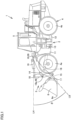
Fig. 1 is a side view of a wheel loader based on an embodiment. -
Fig. 2 is a schematic block diagram of the wheel loader. -
Fig. 3 illustrates an excavation work by the wheel loader based on the embodiment. -
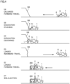
Fig. 4 is a schematic diagram showing an example of a series of work steps included in an excavation operation and a loading operation by the wheel loader. -
Fig. 5 shows a table showing a determination method in the series of work steps included in the excavation operation and the loading operation by the wheel loader. -
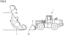
Fig. 6 is a diagram illustrating a piling work by the wheel loader based on the embodiment. -
Fig. 7 is a diagram illustrating a dozing work by the wheel loader based on the embodiment. -
Fig. 8 is a flowchart showing processing for categorization of excavation in a first processor. -
Fig. 9 shows a table for distinguishing contents of works by the wheel loader. -
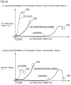
Fig. 10 shows a graph of a trace of a cutting edge of a bucket during works by the wheel loader. -
Fig. 11 shows an exemplary table showing work records. -
Fig. 12 is a schematic diagram showing a ratio of time period for each excavation category. -
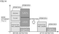
Fig. 13 is a schematic diagram showing a trace of operations by the work implement when an excavation and loading work is extracted. -
Fig. 14 is a schematic diagram showing comparison of an excavation and loading weight per unit fuel consumption amount before and after distinction of work contents. - An embodiment will be described below with reference to the drawings. The same elements have the same reference characters allotted in the description below and their labels and functions are also the same. Therefore, detailed description thereof will not be repeated.
- A
wheel loader 1 will be described by way of example of a work machine in the embodiment.Fig. 1 is a side view ofwheel loader 1 based on the embodiment. - As shown in
Fig. 1 ,wheel loader 1 includes avehicular body frame 2, a work implement 3, a travelingunit 4, and acab 5. Travelingunit 4 includes runningwheels Wheel loader 1 is mobile as runningwheels -
Vehicular body frame 2 has afront frame 11 and arear frame 12.Front frame 11 andrear frame 12 are attached to each other in a manner swingable in a lateral direction. Asteering cylinder 13 is attached tofront frame 11 andrear frame 12. Steeringcylinder 13 is a hydraulic cylinder. As steeringcylinder 13 extends and contracts as being driven by hydraulic oil from a steering pump (not shown), a direction of travel ofwheel loader 1 is laterally changed. - A direction in which
wheel loader 1 travels in straight lines is herein referred to as a fore/aft direction ofwheel loader 1. In the fore/aft direction ofwheel loader 1, a side where work implement 3 is arranged with respect tovehicular body frame 2 is defined as the fore direction and a direction opposite to the fore direction is defined as the aft direction. A lateral direction ofwheel loader 1 is a direction orthogonal to the fore/aft direction in a plan view. A right side and a left side in the lateral direction in facing front are defined as a right direction and a left direction, respectively. An upward/downward direction ofwheel loader 1 is a direction orthogonal to the plane defined by the fore/aft direction and the lateral direction. A side in the upward/downward direction where the ground is located is defined as a lower side and a side where the sky is located is defined as an upper side. - The fore/aft direction refers to a fore/aft direction of an operator who sits at an operator's seat in
cab 5. The lateral direction refers to a lateral direction of the operator who sits at the operator's seat. The lateral direction refers to a direction of a vehicle width ofwheel loader 1. The upward/downward direction refers to an upward/downward direction of the operator who sits at the operator's seat. A direction in which the operator sitting at the operator's seat faces is defined as the fore direction and a direction behind the operator sitting at the operator's seat is defined as the aft direction. A right side and a left side at the time when the operator sitting at the operator's seat faces front are defined as the right direction and the left direction, respectively. A foot side of the operator who sits at the operator's seat is defined as a lower side, and a head side is defined as an upper side. - Work implement 3 and running
wheel 4a are attached tofront frame 11. Work implement 3 includes aboom 14 and abucket 6. A base end ofboom 14 is rotatably attached tofront frame 11 by aboom pin 10.Bucket 6 is rotatably attached to boom 14 by abucket pin 17 located at a tip end ofboom 14.Front frame 11 andboom 14 are coupled to each other by aboom cylinder 16.Boom cylinder 16 is a hydraulic cylinder. Asboom cylinder 16 extends and contracts as being driven by hydraulic oil from a work implement pump 25 (seeFig. 2 ),boom 14 moves upward and downward.Boom cylinder 16drives boom 14. - Work implement 3 further includes a
bell crank 18, atilt cylinder 19, and atilt rod 15. Bell crank 18 is rotatably supported onboom 14 by asupport pin 18a located substantially in the center ofboom 14.Tilt cylinder 19 couples a base end of bell crank 18 andfront frame 11 to each other.Tilt rod 15 couples a tip end of bell crank 18 andbucket 6 to each other.Tilt cylinder 19 is a hydraulic cylinder. Astilt cylinder 19 extends and contracts as being driven by hydraulic oil from work implement pump 25 (seeFig. 2 ),bucket 6 pivots upward and downward.Tilt cylinder 19drives bucket 6. -
Cab 5 and runningwheel 4b are attached torear frame 12.Cab 5 is arranged in the rear ofboom 14.Cab 5 is carried onvehicular body frame 2. A seat where an operator sits and an operation apparatus are arranged incab 5. -
Fig. 2 is a schematic block diagram showing a configuration ofwheel loader 1.Wheel loader 1 includes anengine 20, a motivepower extraction unit 22, a motivepower transmission mechanism 23, acylinder driving unit 24, afirst angle detector 29, asecond angle detector 48, and afirst processor 30. -
Engine 20 is, for example, a diesel engine. Output fromengine 20 is controlled by adjusting an amount of fuel to be injected into a cylinder ofengine 20. - Motive
power extraction unit 22 is an apparatus that distributes output fromengine 20 to motivepower transmission mechanism 23 andcylinder driving unit 24. - Motive
power transmission mechanism 23 is a mechanism that transmits driving force fromengine 20 tofront wheel 4a andrear wheel 4b. Motivepower transmission mechanism 23 changes a speed of rotation of aninput shaft 21 and outputs resultant rotation to anoutput shaft 23a. - A
vehicle speed detector 27 that detects a speed ofwheel loader 1 is attached tooutput shaft 23a of motivepower transmission mechanism 23.Wheel loader 1 includesvehicle speed detector 27.Vehicle speed detector 27 detects a speed of movement ofwheel loader 1 by travelingunit 4 by detecting a rotation speed ofoutput shaft 23a.Vehicle speed detector 27 functions as a rotation sensor that detects a rotation speed ofoutput shaft 23a.Vehicle speed detector 27 functions as a movement detector that detects movement by travelingunit 4.Vehicle speed detector 27 outputs a detection signal representing a vehicle speed ofwheel loader 1 tofirst processor 30. -
Cylinder driving unit 24 includes work implementpump 25 and acontrol valve 26. Output fromengine 20 is transmitted to work implementpump 25 through motivepower extraction unit 22. Hydraulic oil delivered from work implementpump 25 is supplied toboom cylinder 16 andtilt cylinder 19 throughcontrol valve 26. - First
hydraulic pressure detectors boom cylinder 16 are attached toboom cylinder 16.Wheel loader 1 includes firsthydraulic pressure detectors hydraulic pressure detectors pressure sensor 28a for head pressure detection and apressure sensor 28b for bottom pressure detection. -
Pressure sensor 28a is attached to a head side ofboom cylinder 16.Pressure sensor 28a can detect a pressure (a head pressure) of hydraulic oil in the oil chamber on a side of a cylinder head ofboom cylinder 16.Pressure sensor 28a outputs a detection signal representing a head pressure ofboom cylinder 16 tofirst processor 30. -
Pressure sensor 28b is attached to a bottom side ofboom cylinder 16.Pressure sensor 28b can detect a pressure (a bottom pressure) of hydraulic oil in the oil chamber on a side of a cylinder bottom ofboom cylinder 16.Pressure sensor 28b outputs a detection signal representing a bottom pressure ofboom cylinder 16 tofirst processor 30. - For example, a potentiometer attached to
boom pin 10 is employed asfirst angle detector 29.First angle detector 29 detects a boom angle representing a lift angle (a tilt angle) ofboom 14.First angle detector 29 outputs a detection signal representing a boom angle tofirst processor 30. - Specifically, as shown in
Fig. 1 , a boom angle θ represents an angle of a straight line LB extending in a direction from the center ofboom pin 10 toward the center ofbucket pin 17 with respect to a horizontal line LH extending forward from the center ofboom pin 10. A case that straight line LB is horizontal is defined as boom angle θ = 0°. A case that straight line LB is located above horizontal line LH is defined as a positive boom angle θ. A case that straight line LB is located below horizontal line LH is defined as a negative boom angle θ. - A stroke sensor arranged in
boom cylinder 16 may be employed asfirst angle detector 29. - For example, a potentiometer attached to support
pin 18a is employed assecond angle detector 48.Second angle detector 48 detects a bucket angle representing a tilt angle ofbucket 6 with respect to boom 14 by detecting an angle of bell crank 18 (bell crank angle) with respect toboom 14.Second angle detector 48 outputs a detection signal representing a bucket angle tofirst processor 30. The bucket angle is, for example, an angle formed between straight line LB and a straight line that connects the center ofbucket pin 17 and acutting edge 6a ofbucket 6 to each other. When cuttingedge 6a ofbucket 6 is located above straight line LB, the bucket angle is defined as positive. - A stroke sensor arranged in
tilt cylinder 19 may be employed assecond angle detector 48. -
Wheel loader 1 includes incab 5, an operation apparatus operated by an operator. The operation apparatus includes a forward and rearwardtravel switching apparatus 49, anaccelerator operation apparatus 51, aboom operation apparatus 52, abucket operation apparatus 54, and abrake operation apparatus 58. - Forward and rearward
travel switching apparatus 49 includes anoperation member 49a and a memberposition detection sensor 49b.Operation member 49a is operated by an operator for indicating switching between forward travel and rearward travel of the vehicle.Operation member 49a can be switched to a position of each of forward travel (F), neutral (N), and rearward travel (R). Memberposition detection sensor 49b detects a position ofoperation member 49a. Memberposition detection sensor 49b outputs tofirst processor 30, a detection signal (forward travel, neutral, or rearward travel) representing a command to travel forward or rearward indicated by a position ofoperation member 49a. -
Accelerator operation apparatus 51 includes anaccelerator operation member 51a and an acceleratoroperation detection unit 51b.Accelerator operation member 51a is operated by an operator for setting a target rotation speed ofengine 20. Acceleratoroperation detection unit 51b detects an amount of operation ontoaccelerator operation member 51a (an amount of accelerator operation). Acceleratoroperation detection unit 51b outputs a detection signal representing an amount of accelerator operation tofirst processor 30. -
Brake operation apparatus 58 includes abrake operation member 58a and a brakeoperation detection unit 58b.Brake operation member 58a is operated by an operator for controlling deceleration force ofwheel loader 1. Brakeoperation detection unit 58b detects an amount of operation ontobrake operation member 58a (an amount of brake operation). Brakeoperation detection unit 58b outputs a detection signal representing an amount of brake operation tofirst processor 30. A pressure of brake oil may be used as an amount of brake operation. -
Boom operation apparatus 52 includes aboom operation member 52a and a boomoperation detection unit 52b.Boom operation member 52a is operated by an operator for raising or loweringboom 14. Boomoperation detection unit 52b detects a position ofboom operation member 52a. Boomoperation detection unit 52b outputs tofirst processor 30, a detection signal representing a command to raise orlower boom 14 indicated by the position ofboom operation member 52a. -
Bucket operation apparatus 54 includes abucket operation member 54a and a bucketoperation detection unit 54b.Bucket operation member 54a is operated by an operator for causingbucket 6 to perform an excavation operation or a dumping operation. Bucketoperation detection unit 54b detects a position ofbucket operation member 54a. Bucketoperation detection unit 54b outputs tofirst processor 30, a detection signal representing a command to operatebucket 6 in an excavation direction or a dump direction indicated by a position ofbucket operation member 54a. -
First angle detector 29,second angle detector 48, firsthydraulic pressure detectors operation detection unit 52b, and bucketoperation detection unit 54b are included in a work implement sensor. The work implement sensor senses a state of work implement 3. A weight of loads inbucket 6 can be calculated based on a detection value from the work implement sensor. The work implement sensor includes at least one of a pressure sensor and a strain sensor. The work implement sensor includes a work implement position sensor. The work implement position sensor is constituted, for example, offirst angle detector 29,second angle detector 48, boomoperation detection unit 52b, and bucketoperation detection unit 54b. -
First processor 30 is implemented by a microcomputer including a storage such as a random access memory (RAM) or a read only memory (ROM) and a computing device such as a central processing unit (CPU).First processor 30 may be implemented as some of functions of a controller ofwheel loader 1 that controls operations ofengine 20, work implement 3, and motivepower transmission mechanism 23. A signal representing a vehicle speed ofwheel loader 1 detected byvehicle speed detector 27, a signal representing a boom angle detected byfirst angle detector 29, a signal representing a bottom pressure ofboom cylinder 16 detected bypressure sensor 28b, and a signal representing a forward and rearward travel command detected by forward and rearwardtravel switching apparatus 49 are input tofirst processor 30.First processor 30 obtains by summation, work information on transportation of loads inbucket 6 based on the input signals. - The transportation work information refers, for example, to the number of times of transportation works, a total weight in transportation, a total distance of transportation, and a total workload. The number of times of transportation works represents the number of times of prescribed transportation works such as V-shape loading during a period from start until end of summation. The period from start until end of summation means, for example, a period for which an operator drives
wheel loader 1 within a prescribed time period such as one day. The period is desirably managed for each operator. The period may manually be set by an operator. The total weight in transportation means a total weight of loads transported bybucket 6 during a period from start until end of summation. The total distance of transportation means a total distance of movement ofwheel loader 1 withbucket 6 being loaded during a period from start until end of summation. The total workload means a product of the total weight in transportation and the total distance of transportation during a period from start until end of summation. - A signal representing a bucket angle detected by
second angle detector 48 is input tofirst processor 30.First processor 30 calculates a current position of cuttingedge 6a ofbucket 6 based on a signal representing a vehicle speed ofwheel loader 1, a signal representing a boom angle, and a signal representing a bucket angle. -
Wheel loader 1 further includes adisplay 40 and anoutput unit 45.Display 40 is implemented by a monitor arranged incab 5 and viewed by an operator.Display 40 shows transportation work information obtained by summation byfirst processor 30. -
Output unit 45 outputs transportation work information to a server (a second processor 70) providedoutside wheel loader 1.Output unit 45 may have a communication function such as wireless communication and may communicate with aninput unit 71 ofsecond processor 70. Alternatively,output unit 45 may be implemented, for example, by an interface of a portable storage (such as a memory card) that can be accessed frominput unit 71 ofsecond processor 70.Second processor 70 includes adisplay 75 that performs a monitor function and can show transportation work information output fromoutput unit 45. -
Wheel loader 1 in the present embodiment performs an excavation work for scooping an excavated object such as soil.Fig. 3 illustrates an excavation work bywheel loader 1 based on the embodiment. - As shown in
Fig. 3 ,wheel loader 1pushes cutting edge 6a ofbucket 6 into an excavatedobject 100 and thereafter raisesbucket 6 along a bucket trace L as shown with a curved arrow inFig. 3 . The excavation work for scooping excavatedobject 100 is thus performed. -
Wheel loader 1 in the present embodiment performs an excavation operation for scooping excavatedobject 100 inbucket 6 and a loading operation for loading objects (excavated object 100) inbucket 6 onto a transportation machine such as adump truck 200.Fig. 4 is a schematic diagram showing an example of a series of work steps included in an excavation operation and a loading operation bywheel loader 1 based on the embodiment.Wheel loader 1 excavates excavatedobject 100 and loads excavatedobject 100 on a transportation machine such asdump truck 200 by successively repeating a plurality of works steps as follows. - As shown in
Fig. 4 (A) ,wheel loader 1 travels forward toward excavatedobject 100. In this unloaded forward travel step, an operator operatesboom cylinder 16 andtilt cylinder 19 to set work implement 3 to an excavation attitude in which the tip end ofboom 14 is located at a low position andbucket 6 is horizontally oriented, and moveswheel loader 1 forward toward excavatedobject 100. - As shown in
Fig. 4 (B) , the operator moveswheel loader 1 forward until cuttingedge 6a ofbucket 6 is pushed into excavatedobject 100. In this excavation (pushing) step, cuttingedge 6a ofbucket 6 is pushed into excavatedobject 100. - As shown in
Fig. 4 (C) , the operator thereafter operatesboom cylinder 16 to raisebucket 6 and operatestilt cylinder 19 to tilt backbucket 6. In this excavation (scooping) step,bucket 6 is raised along bucket trace L as shown with an arrow in the figure and excavatedobject 100 is scooped intobucket 6. An excavation work for scooping excavatedobject 100 is thus performed. - Depending on a type of excavated
object 100, the scooping step may be completed simply by tilting backbucket 6 once. Alternatively, in the scooping step, an operation to tilt backbucket 6, set the bucket to a neutral position, and tilt back the bucket again may be repeated. - As shown in
Fig. 4 (D) , after excavatedobject 100 is scooped intobucket 6, the operator moveswheel loader 1 rearward in a loaded rearward travel step. The operator may raise the boom while moving the vehicle rearward, or may raise the boom while moving the vehicle forward inFig. 4 (E) . - As shown in
Fig. 4 (E) , the operator moveswheel loader 1 forward to be closer to dumptruck 200 while keepingbucket 6 raised or raisingbucket 6. As a result of this loaded forward travel step,bucket 6 is located substantially directly above a box ofdump truck 200. - As shown in
Fig. 4 (F) , the operator dumps the excavated object frombucket 6 at a prescribed position and loads objects (excavated object) inbucket 6 on the box ofdump truck 200. This step is what is called a soil ejection step. Thereafter, the operator lowersboom 14 and returnsbucket 6 to the excavation attitude while the operator moveswheel loader 1 rearward. - The above is typical work steps defining one cycle of the excavation and loading work.
-
Fig. 5 shows a table showing a determination method in the series of work steps included in the excavation operation and the loading operation bywheel loader 1. - In the table shown in
Fig. 5 , a row of "work step" at the top lists names of work steps shown inFig. 4 (A) to (F) . In rows of "forward and rearward travel switching lever," "operation of work implement," and "pressure of cylinder of work implement" below, various criteria used by first processor 30 (Fig. 2 ) for determining under which step a current work step falls are shown. - More specifically, in the row of "forward and rearward travel switching lever," criteria for an operation performed by an operator onto a forward and rearward travel switching lever (
operation member 49a) are shown with a circle. - In the row of "operation of work implement," criteria for an operation by an operator onto work implement 3 are shown with a circle. More specifically, in a row of "boom", criteria for an operation onto
boom 14 are shown, and in a row of "bucket", criteria for an operation ontobucket 6 are shown. - In the row of "pressure of cylinder of work implement," criteria for a current hydraulic pressure of the cylinder of work implement 3 such as a hydraulic pressure of a cylinder bottom chamber of
boom cylinder 16 are shown. Four reference values A, B, C, and P are set in advance for a hydraulic pressure, a plurality of pressure ranges (a range lower than reference value P, a range of reference values A to C, a range of reference values B to P, and a range lower than reference value C) are defined by reference values A, B, C, and P, and these pressure ranges are set as the criteria. Magnitude of four reference values A, B, C, and P is defined as A > B > C > P. - By using a combination of criteria for "forward and rearward travel switching lever," "boom", "bucket", and "pressure of cylinder of work implement" for each work step as above,
first processor 30 can determine under which work step a currently performed work falls. - A specific operation of
first processor 30 when control shown inFig. 5 is carried out will be described below. - A combination of criteria for "forward and rearward travel switching lever," "boom", "bucket", and "pressure of cylinder of work implement" corresponding to each work step shown in
Fig. 5 is stored in advance in astorage 30j (Fig. 2 ).First processor 30 recognizes a type (F, N, or R) of a current operation onto the forward and rearward travel switching lever based on a signal from forward and rearwardtravel switching apparatus 49.First processor 30 recognizes a type of a current operation onto boom 14 (lowering, neutral, or raising) based on a signal from boomoperation detection unit 52b.First processor 30 recognizes a type of a current operation onto bucket 6 (dump, neutral, or tilt back) based on a signal from bucketoperation detection unit 54b.First processor 30 recognizes a current hydraulic pressure of the cylinder bottom chamber ofboom cylinder 16 based on a signal frompressure sensor 28b shown inFig. 2 . -
First processor 30 compares combination of the recognized type of operation onto the forward and rearward travel switching lever, the type of the operation onto the boom, the type of the operation onto the bucket, and the hydraulic pressure of the boom cylinder at the current time point (that is, a current state of work) with combination of criteria for "forward and rearward travel switching lever," "boom", "bucket", and "pressure of cylinder of work implement" corresponding to each work step stored in advance. As a result of this comparison processing,first processor 30 determines to which work step the combination of criteria which matches best with the current state of work corresponds. - The combination of criteria corresponding to each work step included in the excavation and loading operation shown in
Fig. 5 is specifically as follows. - In the unloaded forward travel step, the forward and rearward travel switching lever is set to F, the operation of the boom and the operation of the bucket are both set to neutral, and the pressure of the cylinder of the work implement is lower than reference value P.
- In the excavation (pushing) step, the forward and rearward travel switching lever is set to F, the operation of the boom and the operation of the bucket are both neutral, and the pressure of the cylinder of the work implement is within the range of reference values A to C.
- In the excavation (scooping) step, the forward and rearward travel switching lever is set to F or R, the operation of the boom is raising or neutral, the operation of the bucket is tilt back, and the pressure of the cylinder of the work implement is within the range of reference values A to C. For an operation of the bucket, such a criterion that tilt back and neutral are alternately repeated may further be added because, depending on a state of excavated
object 100, an operation to tilt backbucket 6, set the bucket to a neutral position, and tilt back the bucket again may be repeated. - In the loaded rearward travel step, the forward and rearward travel switching lever is set to R, the operation of the boom is neutral or raising, the operation of the bucket is neutral, and the pressure of the cylinder of the work implement is within the range of reference values B to P.
- In the loaded forward travel step, the forward and rearward travel switching lever is set to F, the operation of the boom is raising or neutral, the operation of the bucket is neutral, and the pressure of the cylinder of the work implement is within the range of reference values B to P.
- In the soil ejection step, the forward and rearward travel switching lever is set to F, the operation of the boom is raising or neutral, the operation of the bucket is dump, and the pressure of the cylinder of the work implement is within the range of reference values B to P.
- In the rearward travel · boom lowering step, the forward and rearward travel switching lever is set to R, the operation of the boom is lowering, the operation of the bucket is tilt back, and the pressure of the cylinder of the work implement is lower than reference value P.
-
Fig. 5 further shows a simple travel step in whichwheel loader 1 simply travels. In the simple travel step, the operator moveswheel loader 1 forward withboom 14 being located at a low position. The wheel loader may transport loads withbucket 6 being loaded, or the wheel loader may travel withbucket 6 being unloaded. In the simple travel step, the forward and rearward travel switching lever is set to F (in travel forward; set to R in travel rearward), the operation of the boom is neutral, the operation of the bucket is neutral, and the pressure of the cylinder of the work implement is lower than reference value C. -
Wheel loader 1 in the present embodiment performs a piling work in which excavatedobject 100 such as soil scooped intobucket 6 is ejected at the site and piled up.Fig. 6 is a diagram illustrating a piling work bywheel loader 1 based on the embodiment. - As shown in
Fig. 6 ,wheel loader 1pushes cutting edge 6a ofbucket 6 into excavatedobject 100 and thereafter raisesbucket 6 along bucket trace L as shown with a curved arrow inFig. 6 .Wheel loader 1further causes bucket 6 to perform a dumping operation. The piling work in which excavatedobject 100 scooped inbucket 6 is ejected at the site and piled up is thus performed. - In the piling work, the dumping operation by
bucket 6 is performed at the end of the work. Therefore, the position ofboom 14 at the end of the work is often higher than in the excavation and loading work. In performing the piling work,wheel loader 1 may go up the slope of the pile of excavatedobject 100 so as to eject excavatedobject 100 scooped intobucket 6 at a higher position. -
Wheel loader 1 in the present embodiment performs a dozing (land grading) work for leveling the ground by traveling with cuttingedge 6a ofbucket 6 being located around the ground.Fig. 7 is a diagram illustrating a dozing work bywheel loader 1 based on the embodiment. - As shown in
Fig. 7 , afterbucket 6 is arranged such thatcutting edge 6a is located around the ground,wheel loader 1 travels forward as shown with an arrow inFig. 7 . The dozing work for land grading by leveling of the ground by cuttingedge 6a ofbucket 6 is thus performed. At the end of the dozing work, in order to eject soil that has enteredbucket 6,bucket 6 may be caused to perform the dumping operation. - In
wheel loader 1 in the present embodiment,first processor 30 determines under which of dozing, piling, and excavation and loading contents of works by work implement 3 fall. Such distinction among contents of works is defined as categorization of excavation.Fig. 8 is a flowchart showing processing for categorization of excavation infirst processor 30. - As shown in
Fig. 8 , initially in step S11, whether or not the work step falls under excavation is determined.First processor 30 compares combination of a type of operation onto the forward and rearward travel switching lever, a type of operation onto the boom, a type of operation onto the bucket, and a hydraulic pressure of the boom cylinder at the current time point (that is, a current state of work) with combination of criteria for "forward and rearward travel switching lever," "boom", "bucket", and "pressure of cylinder of work implement" corresponding to each work step stored in advance as described with reference toFigs. 4 and5 and determines whether or not the current work step falls under excavation. - When the work step is determined as falling under excavation (YES in step S11), the excavation work is categorized in steps S12, S14, and S16. Specifically, under which of dozing, piling, and excavation and loading the excavation work falls is determined. Processing in steps S12, S14, and S16 is performed every sampling period of
first processor 30, that is, in real time. - In step S12, whether or not a dozing work is being performed in the work step determined as falling under excavation is initially determined.
Fig. 9 shows a table for distinguishing contents of works bywheel loader 1.Fig. 10 shows a graph of a trace of cuttingedge 6a ofbucket 6 during works bywheel loader 1. The abscissa inFig. 10 (1) represents a trace of cuttingedge 6a (cutting edge trace X, unit of m) ofbucket 6 in a horizontal direction and the ordinate inFig. 10 (1) represents a trace of cuttingedge 6a (cutting edge trace Y, unit of m) ofbucket 6 in a vertical direction. The abscissa inFig. 10 (2) represents cutting edge trace X as inFig. 10 (1) and the ordinate inFig. 10 (2) represents a bucket angle (unit of°) described with reference toFigs. 1 and2 . -
Fig. 9 (A) shows a table for determining whether or not contents of works bywheel loader 1 fall under the dozing work. A curve (A) inFig. 10 (1) shows exemplary relation between horizontal cutting edge trace X and vertical cutting edge trace Y during the dozing work. A curve (A) inFig. 10 (2) shows exemplary relation between horizontal cutting edge trace X and a bucket angle during the dozing work. - As described with reference to
Fig. 7 ,wheel loader 1 travels forward with cuttingedge 6a ofbucket 6 being arranged around the ground while it performs the dozing work. A height of vertical upward movement of cuttingedge 6a during the dozing work is considerably smaller than a length of horizontal movement of cuttingedge 6a with travel ofwheel loader 1. As shown with the curve (A) inFig. 10 (1), it can be seen that cutting edge trace X is longer than cutting edge trace Y in the dozing work, as compared with the cutting edge trace in the piling work or the excavation and loading work which will be described later. - Then, whether or not work contents fall under the dozing work is determined based on cutting edge trace X and cutting edge trace Y. Specifically, a coordinate of cutting edge trace X and cutting edge trace Y at a position of cutting
edge 6a ofbucket 6 at the end of the work is compared with a table where relation between cutting edge trace X and cutting edge trace Y is stored so that whether or not the work contents fall under the dozing work is determined. - More specifically, when the coordinate of cutting edge trace X and cutting edge trace Y at the position of cutting
edge 6a ofbucket 6 at the end of the work is included within a range in the table in which distinction as the dozing work is made, distinction as the dozing work is made. For example, when the position of cuttingedge 6a ofbucket 6 is close to the ground relative to the travel distance ofwheel loader 1 and an operation to raiseboom 14 is not performed or when the operation to raiseboom 14 is performed but an amount of upward movement is small, the work contents are distinguished as the dozing work. - Alternatively, whether or not work contents fall under the dozing work can be determined also simply by comparing cutting edge trace X with a prescribed value without using cutting edge trace Y. For example, when a value of the coordinate of cutting edge trace X at the position of cutting
edge 6a ofbucket 6 at the end of the work is equal to or larger than a prescribed value, a travel distance ofwheel loader 1 until the end of the work is long, and in this case, the work contents are distinguished as the dozing work. - In order to eject soil at the end of the dozing work, as shown in
Fig. 9 (A) , afterboom 14 is once raised,bucket 6 is operated to perform dumping. Whether or not work contents fall under the dozing work may be determined based on change in operation onto the forward and rearward travel switching lever, change in operation onto the boom, change in operation onto the bucket, change in cutting edge trace X, change in cutting edge trace Y, change in bucket angle, or combination thereof. - When the work contents are distinguished as dozing in step S12 in
Fig. 8 , the process proceeds to step S13 and the work contents are stored with the excavation category being defined as dozing. - When the work contents are not distinguished as dozing in step S12, the process proceeds to step S14 and whether or not the excavation and loading work is being performed is determined.
Fig. 9 (B) shows a table for determining whether or not contents of works bywheel loader 1 fall under the excavation and loading work. A curve (B) inFig. 10 (1) represents exemplary relation between horizontal cutting edge trace X and vertical cutting edge trace Y during the excavation and loading work. A curve (B) inFig. 10 (2) shows exemplary relation between horizontal cutting edge trace X and a bucket angle during the excavation and loading work. - When excavation and loading shown in
Fig. 3 is performed, in order to scoop soil, a tilt back operation is performed during excavation as shown in the table inFig. 9 (B) . As shown with the curve B inFig. 10 (2), a bucket angle is thus larger than in the piling work or the dozing work near the end of excavation. - Then, whether or not work contents fall under the excavation and loading work is determined based on a bucket angle. Specifically, whether or not work contents fall under the excavation and loading work is determined by comparing the bucket angle with a prescribed value. More specifically, when the bucket angle at the end of the work is larger than the prescribed value, work contents are distinguished as the excavation and loading work. Whether or not work contents fall under the excavation and loading work may be determined based on change in operation onto the forward and rearward travel lever, change in boom angle, change in bucket angle, change in cutting edge trace, or combination thereof.
- When the work contents are distinguished as excavation and loading in step S14 in
Fig. 8 , the process proceeds to step S15 and the work contents are stored with the excavation category being defined as excavation and loading. - When work contents are not distinguished as excavation and loading in step S14, the process proceeds to step S16 and whether or not a piling work is being performed is determined.
Fig. 9 (C) shows a table for determining whether or not contents of works bywheel loader 1 fall under a piling work. A curve (C) inFig. 10(1) represents exemplary relation between horizontal cutting edge trace X and vertical cutting edge trace Y during the piling work. A curve (C) inFig. 10 (2) represents exemplary relation between horizontal cutting edge trace X and a bucket angle during the piling work. - In piling, as shown in the table in
Fig. 9 (C) , the dumping operation for ejecting soil inbucket 6 is performed near the end of excavation. Then, whether or not work contents fall under a piling work is determined based on the dumping operation ofbucket 6 during excavation. - The dumping operation is performed near the end of excavation. Therefore, as shown with the curve (C) in
Fig. 10 (1), cutting edge trace Y changes from raising to lowering. Therefore, whether or not the work contents fall under the piling work may be determined based on cutting edge trace Y. - As shown with the curve (C) in
Fig. 10 (2), a value of a bucket angle is smaller than in excavation and loading. Therefore, whether or not work contents fall under a piling work may be determined based on a bucket angle. - When work contents are distinguished as piling in step S16 in
Fig. 9 , the process proceeds to step S17 and the work contents are stored with the excavation category being defined as piling. - When work contents are not distinguished as piling in step S16, the process proceeds to step S18 and the work contents are stored with the excavation category being unknown.
- Excavation is categorized as unknown, for example, immediately after start of excavation. As shown in
Fig. 9 (A) to (C) and shown with the curves (A) to (C) inFig. 10 , at a time point of start of excavation, there is no great difference in operation by the work implement among excavation and loading, piling, and dozing, and hence the excavation category may be determined as unknown. - As shown in
Figs. 9 and10 , a difference among dozing, excavation and loading, and piling becomes noticeable near the end of excavation. Therefore, an operation onto the forward and rearward travel switching lever may be added to the criteria as a condition for recognizing that excavation is in the last stage. - Based on data on distinction about the excavation category calculated in real time in steps S12 to
S 18 inFig. 8 , time, the work step, and the excavation category are cumulatively recorded in step S19. In other words, data on which a table shown inFig. 11 which will be described later is based is recorded. - When the work step is not determined as falling under excavation (NO in step S11), whether or not the immediately preceding work step falls under excavation is determined in step S20. In step S20, whether or not the work step has proceeded from excavation to a work step other than excavation (excavation has ended) is determined.
- When the immediately preceding work step is determined as excavation in step S20 (YES in step S20), the excavation category during a period from transition of the work step from a work step other than excavation to excavation until transition of the work step from excavation to a work step other than excavation, that is, from start of excavation until end of excavation, is updated in step S21.
- Under which of dozing, piling, and excavation and loading contents of works by work implement 3 fall is thus determined (end in
Fig. 8 ). -
Fig. 11 shows an exemplary table showing work records.Fig. 11 shows a work step, work contents in the excavation step, and an excavation category representing work contents from a time point of start of the work until a time point of end of the work in the excavation step, at each time point fromtime 0 totime 24. - During a period from
time 0 to 5, the work step falls under unloaded forward travel. During a period fromtime 6 to 21, the work step falls under excavation. During a period fromtime 22 to 24, the work step falls under loaded rearward travel. Since the work step does not fall under the excavation step during the period fromtime 0 to 5 and fromtime 22 to 24, work contents are not distinguished in accordance with a flow of the process shown inFig. 8 . - For example, when an operator operates forward and rearward
travel switching apparatus 49 attime 13 and a rearward travel command is issued, work contents are distinguished as excavation and loading in accordance with the flow of the process shown inFig. 8 . - For example, when the operator operates
bucket operation apparatus 54 attime 18 and a bucket dump command is issued, work contents are distinguished as piling in accordance with the flow of the process shown inFig. 8 . - After excavation ends,
first processor 30 updates work contents during a period from start of the work (time 6) until end of the work (time 21) in the excavation step to work contents distinguished at the end of the work attime 21, that is, piling. Updated work contents during the period fromtime 6 to 21 are shown in a column of the excavation category (after update) in the table inFig. 11 . - Though
first processor 30 distinguishes among dozing, piling, and excavation and loading in real time at each time fromtime 6 to 21, it does not immediately identify work contents distinguished at each time as work contents at each time but it identifies work contents during a period from start of the work until end of the work based on a result of distinction between at least two temporally distant work contents in work records during the period from the start of the work until the end of the work. As shown inFig. 11 , though work contents are distinguished, for example, as excavation and loading attime 13, work contents are identified as piling also attime 13 based on the fact that work contents are distinguished as piling atlater time 21. - An example in which work contents during a period from start of the work until the end of the work are identified as piling and the work contents during the period from the start of the work until the end of the work are updated to piling is described with reference to
Fig. 11 . Similarly, work contents can be identified as excavation and loading based on a result of distinction between at least two temporally distant work contents in work records during a period from start of the work until the end of the work and the work contents during the period from start of the work until the end of the work can be updated to excavation and loading. Further similarly, work contents can be identified as dozing and the work contents during the period from start of the work until the end of the work can be updated to dozing. - For example, when
bucket operation apparatus 54 is not operated attime 18 shown inFig. 11 and no bucket dump command is issued, work contents are distinguished as falling under excavation and loading attime 21. In that case, work contents during the period from start of the work until the end of the work can be updated to excavation and loading. -
First processor 30 shown inFig. 2 can output a result of work such as the cumulative number of times of work, a cumulative duration of work, and a cumulative amount of fuel consumption for each excavation category of dozing, piling, and excavation and loading identified as work contents during a period from start until end.Fig. 12 is a schematic diagram showing a ratio of a time period for each excavation category.Fig. 12 shows an example in which display 40 shows that approximately 70% of contents of work performed by an operator A falls under excavation and loading, approximately 55% of contents of work performed by an operator B falls under excavation and loading, operator A performs more work contributing productivity than operator B, and hence fuel efficiency (an amount of excavation and loading per unit fuel consumption amount) involved with work by operator A is higher than fuel efficiency involved with work by operator B. -
First processor 30 can extract specific work contents from work contents of dozing, piling, and excavation and loading.First processor 30 can output a trace of operations by work implement 3 in extracted specific work contents.Fig. 13 is a schematic diagram showing a trace of operations by work implement 3 when an excavation and loading work is extracted.Fig. 13 shows an example in which a graph with the abscissa representing cutting edge trace X and the ordinate representing cutting edge trace Y shows a trace of operations by cuttingedge 6a ofbucket 6 during a period from start until end of works by operator A and operator B. -
Fig. 13 also shows an example in which display 40 shows an extraction and selection section.Fig. 13 shows an example in which excavation and loading is selected as an item to be extracted and a trace of operations by cuttingedge 6a ofbucket 6 at the time when each operator performs excavation and loading is shown. By extracting the trace of operations by cuttingedge 6a at the time when a skilled operator performs excavation and loading and using this data for training an unexperienced operator, the operator can efficiently be trained. - When
display 40 is implemented by a touch panel, the operator can select work contents to be extracted by performing a touch operation onto the extraction and selection section shown inFig. 13 . Alternatively, the extraction and selection section shown inFig. 13 may merely be representation, and a not-shown selection operation member such as a switch or a button may be operated by an operator to select work contents to be extracted. - By showing an operation onto forward and rearward
travel switching apparatus 49,accelerator operation apparatus 51,boom operation apparatus 52,bucket operation apparatus 54, andbrake operation apparatus 58 as well as a bucket angle in addition to the trace of operations by cuttingedge 6a ofbucket 6 shown inFig. 13 together ondisplay 40, further effective training can be performed. -
First processor 30 can extract excavation and loading from works in which the boom is raised, that is, piling and excavation and loading, and can calculate an amount of excavation and loading per unit fuel consumption amount for excavation and loading.Fig. 14 is a schematic diagram showing comparison of an excavation and loading weight per unit fuel consumption amount before and after distinction between work contents.Fig. 14 shows comparison of an amount of loading of excavatedobject 100 per unit fuel consumption amount ("work efficiency" shown on the ordinate inFig. 14 , unit of Ton/L) between operator A and operator B "before distinction" which means that distinction between piling and excavation and loading has not been made and "after distinction" which means that only excavation and loading has been extracted. - By calculating an amount of loading per unit fuel consumption amount with only excavation and loading being extracted, net work efficiency of an operator can be evaluated.
- For example, operator A and operator B are compared with each other in terms of work efficiency in
Fig. 14 . Operator A performs excavation and loading more than operator B and operator A performs piling and dozing less than operator B. In other words, operator A performs works contributing more to productivity more than operator B and works by operator A are desirable. - When evaluation is made without extracting excavation and loading, operator A is lower in work efficiency than operator B. Therefore, when works by operator A are evaluated without extraction of excavation and loading, erroneous evaluation that operator A is inferior to operator B is made.
- In contrast, when evaluation is made with excavation and loading being extracted, operator A is higher in work efficiency than operator B. Therefore, work efficiency of operator A can more properly be evaluated.
- Functions and effects of the embodiment described above will now be described.
- In the embodiment,
first processor 30 as the controller identifies work contents during a period from start of work until end of the work based on a result of distinction between at least two temporally distant work contents in work records during the period from start of the work until the end of the work as shown inFig. 11 . A result of distinction between work contents at each time point is not immediately identified as work contents at each time point but work contents during the period from start of the work until the end of the work are identified based on a result of distinction between work contents at at least two temporally distant time points. Therefore, work contents can more accurately be distinguished. - As shown in
Fig. 11 ,first processor 30 as the controller distinguishes work contents at the end of the work and identifies the work contents distinguished at the end of the work as work contents during the period from start of the work until the end of the work. The work contents during the period from start of the work until the end of the work may be updated to the work contents distinguished at the end of the work. According to the configuration in which work contents distinguished at the end of the work replace and update preceding work contents retrospectively rather than a configuration in which a result of distinction between work contents at each time point is immediately identified as work contents at each time point, work contents can more accurately be distinguished. - As shown in
Figs. 8 to 10 ,first processor 30 determines a work step ofwheel loader 1 based on a signal from a sensor that detects a state ofwheel loader 1. As shown inFigs. 8 and11 ,first processor 30 distinguishes work contents during the period from start of the work until the end of the work when the work step falls under the excavation step. According to the configuration in which work contents are not distinguished when the work step does not fall under excavation but work contents are distinguished when the work step falls under excavation, work contents can more accurately be distinguished. - As shown in
Fig. 12 ,display 40 may output a result of work for each work content. By doing so, an operator or a manager can readily recognize at which ratio an excavation and loading work of all contents of works by the work implement is performed and accurately evaluate productivity. -
Display 40 may also output for each work content, results of works by a plurality of operators. Since comparison of evaluation of productivity of the plurality of operators can thus readily be made, the operator can be encouraged to improve productivity. - As shown in
Fig. 14 ,display 40 may output an amount of fuel consumption calculated with excavation and loading being extracted. It may be output together with an amount of fuel consumption of another operator. - As shown in
Fig. 13 , specific work contents such as excavation and loading may be extracted from work contents of dozing, piling, and excavation and loading. By extracting specific work contents, an amount of fuel consumption while those work contents are performed or a weight of excavatedobject 100 loaded onto a dump truck as a result of the excavation and loading work can accurately be calculated. - As shown in
Fig. 13 , an extraction and selection section in which work contents to be extracted are selected from among the work contents described above may be provided. The extraction and selection section may be provided on a display screen as shown inFig. 13 , as an embodiment of extraction. - Though
Fig. 13 shows data on a trace of the cutting edge, shown data is not limited thereto. Records of operations onto an operation apparatus such as the boom operation apparatus, the bucket operation apparatus, the accelerator operation apparatus, or the brake operation apparatus or records of a bucket angle or a boom angle may be shown. - As shown in
Fig. 13 ,display 40 may output a trace of operations by work implement 3 in the extracted specific work contents. For example, a trace of operations in an excavation and loading work by a skilled operator may be output and an unexperienced operator can be trained to operate work implement 3 along the output trace of operations. Training for operations can thus efficiently be performed. - A result of work and a trace of operations by work implement 3 may be output to display 40 or may be output, for example, to display 75 of
second processor 70 through communication tosecond processor 70 viaoutput unit 45 shown inFig. 2 . Alternatively, the result of work and the trace of the operations may be output as a daily report to a not-shown printer connected tosecond processor 70. - As shown in
Figs. 9 and10 ,first processor 30 may distinguish work contents based on a trace ofbucket 6.First processor 30 may find a boom angle and a bucket angle based on detection signals input fromfirst angle detector 29 andsecond angle detector 48, find a vehicle speed ofwheel loader 1 based on a detection signal input fromvehicle speed detector 27, and find a position of cuttingedge 6a ofbucket 6 based thereon.First processor 30 can distinguish work contents as dozing based on the trace of operations bybucket 6 that connects a position of cuttingedge 6a at the start of the work and a position of cuttingedge 6a at the end of the work to each other. -
First processor 30 may distinguish work contents based on a ratio between an angle ofboom 14 with respect to the vehicular body and an angle ofbucket 6 with respect toboom 14.First processor 30 can distinguish work contents as excavation and loading based on the boom angle and the bucket angle. - As shown in
Fig. 9 ,first processor 30 may distinguish work contents based on a result of operations onto forward and rearwardtravel switching apparatus 49.First processor 30 can distinguish work contents as excavation and loading based on issuance of a rearward travel command. - As shown in
Fig. 9 ,first processor 30 may distinguish work contents based on a result of operations ontobucket operation apparatus 54.First processor 30 can distinguish work contents as piling based on issuance of a dump command tobucket 6. - In
Fig. 11 , after the end of excavation,first processor 30 may have work contents during the period fromtime 6 to 21 recorded in another column in the table, instead of updating work contents during the period from start of the work (time 6) until the end of the work (time 21) in the excavation step to work contents distinguished at the end of the work attime 21, that is, to piling. - In the description of the embodiment, an example in which
wheel loader 1 representing the work machine includesfirst processor 30 andfirst processor 30 mounted onwheel loader 1 distinguishes work contents is described. The controller that distinguishes work contents does not necessarily have to be mounted onwheel loader 1. A system in whichfirst processor 30 ofwheel loader 1 performs processing for transmitting detection signals input from various sensors to an external controller and the external controller that has received the detection signals distinguishes work contents may be configured. - In the description of the embodiment, an example in which
wheel loader 1 represents the work machine that performs works including dozing, piling, and excavation and loading is described. The work machine is not limited towheel loader 1 but may be a crawler loader or a backhoe loader. - It should be understood that the embodiment disclosed herein is illustrative and non-restrictive in every respect. The scope of the present invention is defined by the terms of the claims rather than the description above and is intended to include any modifications within the scope and meaning equivalent to the terms of the claims.
- 1 wheel loader; 3 work implement; 6 bucket; 6a cutting edge; 14 boom; 16 boom cylinder; 19 tilt cylinder; 20 engine; 23 motive power transmission mechanism; 27 vehicle speed detector; 28a, 28b first hydraulic pressure detector; 29 first angle detector; 30 first processor; 40, 75 display; 48 second angle detector; 49 forward and rearward travel switching apparatus; 49a operation member; 49b member position detection sensor; 51 accelerator operation apparatus; 51a accelerator operation member; 51b accelerator operation detection unit; 52 boom operation apparatus; 52a boom operation member; 52b boom operation detection unit; 54 bucket operation apparatus; 54a bucket operation member; 54b bucket operation detection unit; 58 brake operation apparatus; 58 brake operation member; 58b brake operation detection unit; 70 second processor; 100 excavated object; 200 dump truck
Claims (18)
- A work machine (1), comprising:a vehicular body;a work implement (3) attached to the vehicular body; anda controller (30) that distinguishes work contents by the work implement including at least two of dozing, piling, and excavation and loading,characterized in thatthe controller (30) is configured to update at end of works the work contents distinguished in real time during a period from start of works until the end of the works, based on at least two results of distinction between a work content distinguished in real time and another work content distinguished at a time point temporally distant from the work content distinguished in real time during the period from the start of the works until the end of the works.
- A work machine (1), comprising:a vehicular body;a work implement (3) attached to the vehicular body; anda controller (30) that is configured to distinguish work contents by the work implement (3) including at least two of dozing, piling, and excavation and loading,characterized in thatthe controller (30) is configured to distinguish the work contents at end of works and to identify the work contents distinguished at the end of the works as the work contents during a period from start of the works until the end of the works.
- The work machine (1) according to claim 1, wherein
the controller (30) is configured to update the work contents during the period from the start of the works until the end of the works, to the work contents distinguished at the end of the works. - The work machine (1) according to claim 1, further comprising at least one sensor (27, 28a, 28b, 29, 48, 52b, 54b) that detects a state of the work machine (1), wherein
the controller (30) is configured to determine a work step of the work machine (1) based on a signal from the sensor (27, 28a, 28b, 29, 48, 52b, 54b), and when the work step falls under an excavation step, the controller (30) is configured to distinguish the work contents during the period from the start of the works until the end of the works. - The work machine (1) according to claim 1, wherein
the controller (30) is configured to output results of the works for each identified work content. - The work machine (1) according to claim 4, wherein
the controller (30) is configured to output for each operator, the results of the works by a plurality of operators. - The work machine (1) according to any one of claims 1 to 5, wherein
the controller (30) is configured to extract specific work contents from the identified work contents. - The work machine (1) according to claim 6, wherein
the controller (30) further includes a selection section in which work contents to be extracted are selected. - The work machine (1) according to claim 6 or 7, wherein
the controller (30) is configured to output a trace of operations by the work implement (3) in the extracted specific work contents. - The work machine (1) according to claim 6 or 7, further comprising an operation apparatus (49, 51, 52, 54, 58) for operating the work machine (1), wherein
the controller (30) is configured to output records of operations onto the operation apparatus (49, 51, 52, 54, 58) in the extracted specific work contents. - The work machine (1) according to claim 6 or 7, further comprising a work implement angle detection device (29, 48) that detects an angle of the work implement (3), wherein the controller (30) is configured to output records of angles of the work implement (3) in the extracted specific work contents.
- The work machine (1) according to any one of claims 1 to 10, whereinthe work implement (3) includes a bucket (6), andthe controller (30) is configured to distinguish the work contents based on a trace of the bucket (6).
- The work machine (1) according to any one of claims 1 to 10, whereinthe work implement (3) includes a boom (14) and a bucket (6), andthe controller (30) is configured to distinguish the work contents based on a ratio between an angle of the boom (14) with respect to the vehicular body and an angle of the bucket (6) with respect to the boom (14).
- The work machine (1) according to any one of claims 1 to 10, further comprising a forward and rearward travel switching apparatus (49) configured to be operated for switching between forward travel and rearward travel of the work machine (1), wherein
the controller (30) is configured to distinguish the work contents based on a result of operation onto the forward and rearward travel switching apparatus (49). - The work machine (1) according to any one of claims 1 to 10, whereinthe work implement (3) includes a bucket (6),the work machine (1) further comprises a bucket operation apparatus (54) operated for operating the bucket (6), andthe controller (30) is configured to distinguish the work contents based on a result of operation onto the bucket operation apparatus (54).
- The work machine (1) according to claim 1, wherein
when the work contents distinguished before the end of the works fall under excavation and loading and the work contents distinguished at the end of the works fall under piling, the controller (30) is configured to identify the work contents during the period from the start of the works until the end of the works as piling. - A system including a work machine (1), the work machine (1) including a vehicular body and a work implement (3) attached to the vehicular body, the system comprising:a controller (30) that distinguishes work contents by the work implement including at least two of dozing, piling, and excavation and loading,characterized in thatthe controller (30) is configured to update at end of works the work contents distinguished in real time during a period from start of works until the end of the works, based on at least two results of distinction between a work content distinguished in real time and another work content distinguished at a time point temporally distant from the work content distinguished in real time during the period from the start of the works until the end of the works.
- A system including a work machine (1), the work machine (1) including a vehicular body and a work implement (3) attached to the vehicular body, the system comprising:a controller (30) that is configured to distinguish work contents by the work implement (3) including at least two of dozing, piling, and excavation and loading,characterized in thatthe controller (30) is configured to distinguish the work contents at end of works and to identify the work contents distinguished at the end of the works as the work contents during a period from start of the works until the end of the works.
Applications Claiming Priority (2)
| Application Number | Priority Date | Filing Date | Title |
|---|---|---|---|
| JP2018055079A JP7123591B2 (en) | 2018-03-22 | 2018-03-22 | Working machines and systems containing working machines |
| PCT/JP2019/005985 WO2019181325A1 (en) | 2018-03-22 | 2019-02-19 | Work machine, and system including work machine |
Publications (3)
| Publication Number | Publication Date |
|---|---|
| EP3656933A1 EP3656933A1 (en) | 2020-05-27 |
| EP3656933A4 EP3656933A4 (en) | 2021-05-05 |
| EP3656933B1 true EP3656933B1 (en) | 2024-04-03 |
Family
ID=67986992
Family Applications (1)
| Application Number | Title | Priority Date | Filing Date |
|---|---|---|---|
| EP19771632.7A Active EP3656933B1 (en) | 2018-03-22 | 2019-02-19 | Work machine and system including work machine |
Country Status (5)
| Country | Link |
|---|---|
| US (1) | US11371217B2 (en) |
| EP (1) | EP3656933B1 (en) |
| JP (1) | JP7123591B2 (en) |
| CN (1) | CN111094663B (en) |
| WO (1) | WO2019181325A1 (en) |
Families Citing this family (3)
| Publication number | Priority date | Publication date | Assignee | Title |
|---|---|---|---|---|
| JP2021085179A (en) * | 2019-11-26 | 2021-06-03 | コベルコ建機株式会社 | Measurement device, operation support system, and construction machine |
| JP7478590B2 (en) | 2020-05-20 | 2024-05-07 | 住友重機械工業株式会社 | Excavator |
| US20220147933A1 (en) * | 2020-11-06 | 2022-05-12 | Moovila, Inc. | Systems and methods for characterizing work by working eqiupment based on proximity to a worker's computing device |
Family Cites Families (19)
| Publication number | Priority date | Publication date | Assignee | Title |
|---|---|---|---|---|
| JPS62274223A (en) | 1986-05-23 | 1987-11-28 | Komatsu Ltd | Load weight detecting method for vehicle |
| JP2613456B2 (en) * | 1988-11-11 | 1997-05-28 | 東洋運搬機株式会社 | Wheel loader work analysis system |
| JP2532791Y2 (en) | 1990-10-24 | 1997-04-16 | 東洋運搬機株式会社 | Bucket tilt control device for earthmoving vehicles |
| US6205687B1 (en) * | 1999-06-24 | 2001-03-27 | Caterpillar Inc. | Method and apparatus for determining a material condition |
| JP2001099701A (en) | 1999-09-30 | 2001-04-13 | Komatsu Ltd | Loaded weight measuring device of loading vehicle |
| US7912612B2 (en) * | 2007-11-30 | 2011-03-22 | Caterpillar Inc. | Payload system that compensates for rotational forces |
| US8660758B2 (en) * | 2007-11-30 | 2014-02-25 | Caterpillar Inc. | Payload system with center of gravity compensation |
| US8930091B2 (en) * | 2010-10-26 | 2015-01-06 | Cmte Development Limited | Measurement of bulk density of the payload in a dragline bucket |
| JP5059954B2 (en) | 2011-02-22 | 2012-10-31 | 株式会社小松製作所 | Excavator display system and control method thereof. |
| CN103403268B (en) | 2011-02-22 | 2016-03-16 | 日立建机株式会社 | Wheel loader |
| JP5937499B2 (en) | 2012-12-05 | 2016-06-22 | 鹿島建設株式会社 | Work content classification system and work content classification method |
| US9487931B2 (en) * | 2014-09-12 | 2016-11-08 | Caterpillar Inc. | Excavation system providing machine cycle training |
| US9691025B2 (en) | 2014-09-16 | 2017-06-27 | Caterpillar Inc. | Machine operation classifier |
| JP6450268B2 (en) | 2015-06-24 | 2019-01-09 | 株式会社小松製作所 | Wheel loader and automatic accumulation method of transportation work information of the wheel loader |
| US9732502B2 (en) * | 2015-07-02 | 2017-08-15 | Caterpillar Inc. | Excavation system providing impact detection |
| JP6552916B2 (en) | 2015-08-24 | 2019-07-31 | 株式会社小松製作所 | Wheel loader |
| US9938692B2 (en) | 2016-01-04 | 2018-04-10 | Caterpillar Inc. | Wheel loader payload measurement system linkage acceleration compensation |
| US10733752B2 (en) * | 2017-07-24 | 2020-08-04 | Deere & Company | Estimating a volume of contents in a container of a work vehicle |
| JP6971888B2 (en) | 2018-03-05 | 2021-11-24 | 株式会社小松製作所 | Work vehicle, system including work vehicle, and load weight calculation method for work vehicle |
-
2018
- 2018-03-22 JP JP2018055079A patent/JP7123591B2/en active Active
-
2019
- 2019-02-19 US US16/647,974 patent/US11371217B2/en active Active
- 2019-02-19 CN CN201980004533.8A patent/CN111094663B/en active Active
- 2019-02-19 EP EP19771632.7A patent/EP3656933B1/en active Active
- 2019-02-19 WO PCT/JP2019/005985 patent/WO2019181325A1/en unknown
Also Published As
| Publication number | Publication date |
|---|---|
| US11371217B2 (en) | 2022-06-28 |
| CN111094663B (en) | 2022-03-18 |
| JP7123591B2 (en) | 2022-08-23 |
| EP3656933A1 (en) | 2020-05-27 |
| CN111094663A (en) | 2020-05-01 |
| EP3656933A4 (en) | 2021-05-05 |
| US20200263394A1 (en) | 2020-08-20 |
| JP2019167711A (en) | 2019-10-03 |
| WO2019181325A1 (en) | 2019-09-26 |
Similar Documents
| Publication | Publication Date | Title |
|---|---|---|
| EP3656933B1 (en) | Work machine and system including work machine | |
| JP6242919B2 (en) | Work vehicle | |
| EP3677882B1 (en) | Work vehicle, system including work vehicle, and load weight calculation method for work vehicle | |
| WO2021002245A1 (en) | System including work machine and work machine | |
| JP6009572B2 (en) | Travel management device for transport vehicles | |
| EP3719224B1 (en) | Work machine and system including work machine | |
| US11808007B2 (en) | Earth-moving machine sensing and control system | |
| EP3722521A1 (en) | Work machine and system including work machine | |
| EP3722520A1 (en) | Work machine and system including work machine | |
| EP3779073A1 (en) | Display system for work machine, and method for controlling display system | |
| JP2022096211A (en) | Work vehicle | |
| EP3783156A1 (en) | Display system for wheel loader, and control method for display system | |
| EP3770345A1 (en) | Work-machine display system and control method therefor |
Legal Events
| Date | Code | Title | Description |
|---|---|---|---|
| STAA | Information on the status of an ep patent application or granted ep patent |
Free format text: STATUS: THE INTERNATIONAL PUBLICATION HAS BEEN MADE |
|
| PUAI | Public reference made under article 153(3) epc to a published international application that has entered the european phase |
Free format text: ORIGINAL CODE: 0009012 |
|
| STAA | Information on the status of an ep patent application or granted ep patent |
Free format text: STATUS: REQUEST FOR EXAMINATION WAS MADE |
|
| 17P | Request for examination filed |
Effective date: 20200220 |
|
| AK | Designated contracting states |
Kind code of ref document: A1 Designated state(s): AL AT BE BG CH CY CZ DE DK EE ES FI FR GB GR HR HU IE IS IT LI LT LU LV MC MK MT NL NO PL PT RO RS SE SI SK SM TR |
|
| AX | Request for extension of the european patent |
Extension state: BA ME |
|
| A4 | Supplementary search report drawn up and despatched |
Effective date: 20210407 |
|
| RIC1 | Information provided on ipc code assigned before grant |
Ipc: E02F 9/20 20060101AFI20210330BHEP Ipc: E02F 9/26 20060101ALI20210330BHEP Ipc: G07C 5/02 20060101ALI20210330BHEP Ipc: E02F 3/42 20060101ALI20210330BHEP Ipc: E02F 3/43 20060101ALI20210330BHEP |
|
| DAV | Request for validation of the european patent (deleted) | ||
| DAX | Request for extension of the european patent (deleted) | ||
| STAA | Information on the status of an ep patent application or granted ep patent |
Free format text: STATUS: EXAMINATION IS IN PROGRESS |
|
| 17Q | First examination report despatched |
Effective date: 20230309 |
|
| GRAP | Despatch of communication of intention to grant a patent |
Free format text: ORIGINAL CODE: EPIDOSNIGR1 |
|
| STAA | Information on the status of an ep patent application or granted ep patent |
Free format text: STATUS: GRANT OF PATENT IS INTENDED |
|
| INTG | Intention to grant announced |
Effective date: 20231115 |
|
| GRAS | Grant fee paid |
Free format text: ORIGINAL CODE: EPIDOSNIGR3 |
|
| GRAA | (expected) grant |
Free format text: ORIGINAL CODE: 0009210 |
|
| STAA | Information on the status of an ep patent application or granted ep patent |
Free format text: STATUS: THE PATENT HAS BEEN GRANTED |
|
| AK | Designated contracting states |
Kind code of ref document: B1 Designated state(s): AL AT BE BG CH CY CZ DE DK EE ES FI FR GB GR HR HU IE IS IT LI LT LU LV MC MK MT NL NO PL PT RO RS SE SI SK SM TR |
|
| REG | Reference to a national code |
Ref country code: CH Ref legal event code: EP |
|
| REG | Reference to a national code |
Ref country code: DE Ref legal event code: R096 Ref document number: 602019049570 Country of ref document: DE |