EP3656712A1 - Paper sheet transporting device, paper sheet handling device, and paper sheet transporting method - Google Patents
Paper sheet transporting device, paper sheet handling device, and paper sheet transporting method Download PDFInfo
- Publication number
- EP3656712A1 EP3656712A1 EP17918081.5A EP17918081A EP3656712A1 EP 3656712 A1 EP3656712 A1 EP 3656712A1 EP 17918081 A EP17918081 A EP 17918081A EP 3656712 A1 EP3656712 A1 EP 3656712A1
- Authority
- EP
- European Patent Office
- Prior art keywords
- paper sheet
- banknote
- conveying path
- driving roller
- conveying
- Prior art date
- Legal status (The legal status is an assumption and is not a legal conclusion. Google has not performed a legal analysis and makes no representation as to the accuracy of the status listed.)
- Granted
Links
Images








Classifications
-
- B—PERFORMING OPERATIONS; TRANSPORTING
- B65—CONVEYING; PACKING; STORING; HANDLING THIN OR FILAMENTARY MATERIAL
- B65H—HANDLING THIN OR FILAMENTARY MATERIAL, e.g. SHEETS, WEBS, CABLES
- B65H9/00—Registering, e.g. orientating, articles; Devices therefor
- B65H9/002—Registering, e.g. orientating, articles; Devices therefor changing orientation of sheet by only controlling movement of the forwarding means, i.e. without the use of stop or register wall
-
- B—PERFORMING OPERATIONS; TRANSPORTING
- B65—CONVEYING; PACKING; STORING; HANDLING THIN OR FILAMENTARY MATERIAL
- B65H—HANDLING THIN OR FILAMENTARY MATERIAL, e.g. SHEETS, WEBS, CABLES
- B65H5/00—Feeding articles separated from piles; Feeding articles to machines
- B65H5/06—Feeding articles separated from piles; Feeding articles to machines by rollers or balls, e.g. between rollers
- B65H5/062—Feeding articles separated from piles; Feeding articles to machines by rollers or balls, e.g. between rollers between rollers or balls
-
- B—PERFORMING OPERATIONS; TRANSPORTING
- B65—CONVEYING; PACKING; STORING; HANDLING THIN OR FILAMENTARY MATERIAL
- B65H—HANDLING THIN OR FILAMENTARY MATERIAL, e.g. SHEETS, WEBS, CABLES
- B65H7/00—Controlling article feeding, separating, pile-advancing, or associated apparatus, to take account of incorrect feeding, absence of articles, or presence of faulty articles
- B65H7/02—Controlling article feeding, separating, pile-advancing, or associated apparatus, to take account of incorrect feeding, absence of articles, or presence of faulty articles by feelers or detectors
- B65H7/06—Controlling article feeding, separating, pile-advancing, or associated apparatus, to take account of incorrect feeding, absence of articles, or presence of faulty articles by feelers or detectors responsive to presence of faulty articles or incorrect separation or feed
- B65H7/10—Controlling article feeding, separating, pile-advancing, or associated apparatus, to take account of incorrect feeding, absence of articles, or presence of faulty articles by feelers or detectors responsive to presence of faulty articles or incorrect separation or feed responsive to incorrect side register
-
- B—PERFORMING OPERATIONS; TRANSPORTING
- B65—CONVEYING; PACKING; STORING; HANDLING THIN OR FILAMENTARY MATERIAL
- B65H—HANDLING THIN OR FILAMENTARY MATERIAL, e.g. SHEETS, WEBS, CABLES
- B65H9/00—Registering, e.g. orientating, articles; Devices therefor
- B65H9/10—Pusher and like movable registers; Pusher or gripper devices which move articles into registered position
- B65H9/103—Pusher and like movable registers; Pusher or gripper devices which move articles into registered position acting by friction or suction on the article for pushing or pulling it into registered position, e.g. against a stop
- B65H9/106—Pusher and like movable registers; Pusher or gripper devices which move articles into registered position acting by friction or suction on the article for pushing or pulling it into registered position, e.g. against a stop using rotary driven elements as part acting on the article
-
- B—PERFORMING OPERATIONS; TRANSPORTING
- B65—CONVEYING; PACKING; STORING; HANDLING THIN OR FILAMENTARY MATERIAL
- B65H—HANDLING THIN OR FILAMENTARY MATERIAL, e.g. SHEETS, WEBS, CABLES
- B65H2301/00—Handling processes for sheets or webs
- B65H2301/30—Orientation, displacement, position of the handled material
- B65H2301/36—Positioning; Changing position
- B65H2301/361—Positioning; Changing position during displacement
- B65H2301/3611—Positioning; Changing position during displacement centering, positioning material symmetrically relatively to a given axis of displacement
-
- B—PERFORMING OPERATIONS; TRANSPORTING
- B65—CONVEYING; PACKING; STORING; HANDLING THIN OR FILAMENTARY MATERIAL
- B65H—HANDLING THIN OR FILAMENTARY MATERIAL, e.g. SHEETS, WEBS, CABLES
- B65H2301/00—Handling processes for sheets or webs
- B65H2301/40—Type of handling process
- B65H2301/44—Moving, forwarding, guiding material
- B65H2301/443—Moving, forwarding, guiding material by acting on surface of handled material
- B65H2301/4431—Moving, forwarding, guiding material by acting on surface of handled material by means with operating surfaces contacting opposite faces of material
- B65H2301/44318—Moving, forwarding, guiding material by acting on surface of handled material by means with operating surfaces contacting opposite faces of material between rollers
-
- B—PERFORMING OPERATIONS; TRANSPORTING
- B65—CONVEYING; PACKING; STORING; HANDLING THIN OR FILAMENTARY MATERIAL
- B65H—HANDLING THIN OR FILAMENTARY MATERIAL, e.g. SHEETS, WEBS, CABLES
- B65H2404/00—Parts for transporting or guiding the handled material
- B65H2404/10—Rollers
- B65H2404/14—Roller pairs
- B65H2404/144—Roller pairs with relative movement of the rollers to / from each other
- B65H2404/1441—Roller pairs with relative movement of the rollers to / from each other involving controlled actuator
-
- B—PERFORMING OPERATIONS; TRANSPORTING
- B65—CONVEYING; PACKING; STORING; HANDLING THIN OR FILAMENTARY MATERIAL
- B65H—HANDLING THIN OR FILAMENTARY MATERIAL, e.g. SHEETS, WEBS, CABLES
- B65H2404/00—Parts for transporting or guiding the handled material
- B65H2404/10—Rollers
- B65H2404/15—Roller assembly, particular roller arrangement
- B65H2404/152—Arrangement of roller on a movable frame
- B65H2404/1523—Arrangement of roller on a movable frame moving in parallel to its axis
-
- B—PERFORMING OPERATIONS; TRANSPORTING
- B65—CONVEYING; PACKING; STORING; HANDLING THIN OR FILAMENTARY MATERIAL
- B65H—HANDLING THIN OR FILAMENTARY MATERIAL, e.g. SHEETS, WEBS, CABLES
- B65H2404/00—Parts for transporting or guiding the handled material
- B65H2404/10—Rollers
- B65H2404/16—Details of driving
- B65H2404/161—Means for driving a roller parallely to its axis of rotation, e.g. during its rotation
-
- B—PERFORMING OPERATIONS; TRANSPORTING
- B65—CONVEYING; PACKING; STORING; HANDLING THIN OR FILAMENTARY MATERIAL
- B65H—HANDLING THIN OR FILAMENTARY MATERIAL, e.g. SHEETS, WEBS, CABLES
- B65H2701/00—Handled material; Storage means
- B65H2701/10—Handled articles or webs
- B65H2701/19—Specific article or web
- B65H2701/1912—Banknotes, bills and cheques or the like
Definitions
- the present invention relates to a paper sheet conveying apparatus, a paper sheet handling apparatus, and a paper sheet conveying method.
- a banknote handling apparatus such as an automated teller machine (ATM), a cash dispenser (CD), and a teller cash recycler (TCR), includes a storage unit for storing a banknote deposited.
- ATM automated teller machine
- CD cash dispenser
- TCR teller cash recycler
- the banknote deposited passes through a distinguishing unit that distinguishes true/false or the like of the banknote, and the banknote is stored in the storage unit that is classified into types of currencies.
- the banknote deposited in the banknote handling apparatus is typically stored in the storage unit of the same specification according to the types of currencies even when the banknote varies in size according to the types of currencies.
- a gap is created between the banknotes accumulated and an inner wall of the storage unit.
- some of the banknotes hang down or fall into the gap, causing the banknotes to be stored out of order in the storage unit.
- the banknotes stored out of order in the storage unit causes unstable condition for dispensing of the banknotes when the banknotes are withdrawn from the storage unit.
- types of currencies for withdrawal are limited by, for example, excluding the banknotes smaller in size for deposit only.
- a countermeasure is proposed to align an inner size of the storage unit with the size of the banknote.
- an inner width of the storage unit may be aligned with a width of the banknote that is smaller than a width of a conveying path for the banknote.
- some of the banknotes may be stuck against an input area of the storage unit, causing jamming.
- proposed is a related technique that corrects a conveyed position of each of the banknotes in a width direction of the conveying path so as to convey the banknote at a center on the conveying path.
- Patent Document 1 Japanese Laid-open Patent Publication No. 2016-172619
- the conveying path for the banknote is formed by a pair of upper and lower rollers.
- the pair of upper and lower rollers is previously slid by an out-of-position amount that the banknote conveyed on the conveying path has from the center in the width direction of the conveying path.
- the pair of upper and lower rollers sandwiches the banknote therebetween at the slide position, the pair of upper and lower rollers moves the banknote to the center of the conveying path while holding the banknote sandwiched therebetween.
- the pair of upper and lower rollers is arranged in plural rows along the conveying direction to form the conveying path.
- the banknote is handed from one pair to another pair of upper and lower rollers to be moved to the center on the conveyance path.
- a speed of conveying the banknote may be reduced.
- Such a problem is not limited to a banknote handling apparatus but may similarly arise in an apparatus that handles paper sheets.
- an object of the present disclosure technique is to provide a paper sheet conveying apparatus, a paper sheet handling apparatus, and a paper sheet conveying method, each configured to correct the position of the banknote conveyed on the conveying path in the width direction of the conveying path, for example, without reducing the speed of conveying the banknote.
- a paper sheet conveying apparatus includes: a driving roller and a follower roller.
- the driving roller is configured to rotate about a driving roller shaft in response to a rotational force transmitted from a driving source.
- the follower roller is configured to have a fixed position in a width direction of a conveying path where a paper sheet is conveyed, and rotate about a follower roller shaft in response to rotation of the driving roller while holding the paper sheet sandwiched between the follower roller and the driving roller so as to convey the paper sheet with the driving roller from upstream to downstream on the conveying path.
- the driving roller moves in the width direction of the conveying path while holding the paper sheet sandwiched between the driving roller and the driving roller so as to move the paper sheet to a center in the width direction on the conveying path.
- a banknote is used as an example of a paper sheet, but a paper sheet is not limited thereto.
- Examples of the paper sheet include valuable securities such as bill, check, a gift ticket, various corporation securities, and stock certificate.
- FIG. 1 is a schematic diagram illustrating an example entire side view of a banknote handling apparatus including a banknote conveying apparatus according to a first embodiment.
- a banknote handling apparatus 1 includes a deposit/withdrawal unit 3 for depositing and withdrawing a banknote 2, and a distinguishing unit 4 for distinguishing true/false or the like of the banknote 2 deposited in the deposit/withdrawal unit 3.
- the banknote handling apparatus 1 also includes a temporary accommodating unit 5 and a plurality of storage units 6.
- the temporary accommodating unit 5 takes in the banknote 2 conveyed from the distinguishing unit 4 and temporarily accommodates the banknote 2.
- Each of the plurality of storage units 6 stores the banknote 2 fed from the temporary accommodating unit 5.
- the banknote handling apparatus 1 includes a conveying mechanism 7 for conveying the banknote 2.
- the conveying mechanism 7 includes a conveying path 7a that conveys the banknote 2 between the deposit/withdrawal unit 3, the distinguishing unit 4, the temporary accommodating unit 5, and the storage units 6.
- the banknote handling apparatus 1 includes a banknote conveying apparatus 100 that is positioned between the distinguishing unit 4, the temporary accommodating unit 5, and the storage units 6.
- the banknote conveying apparatus 100 includes the conveying path 7a, into which the banknote 2 is conveyed from the distinguishing unit 4.
- the banknote conveying apparatus 100 corrects a position of the banknote 2 in an orthogonal direction to a conveying direction on the conveying path 7a.
- the banknote handling apparatus 1 includes a control unit 8 that controls each of the deposit/withdrawal unit 3, the distinguishing unit 4, the temporary accommodating unit 5, the storage units 6, the conveying mechanism 7, and the banknote conveying apparatus 100.
- an orthogonal coordinate system (X, Y, Z) is used as illustrated in FIG. 1 and subsequent drawings.
- the orthogonal coordinate system (X, Y, Z) has a Z-axis where a vertical height direction of the banknote handling apparatus 1 is referred to as a positive direction.
- the orthogonal coordinate system (X, Y, Z) has a Y-axis that extends from the deposit/withdrawal unit 3 toward the temporary accommodating unit 5 in the banknote handling apparatus 1 as a positive direction and that extends vertically to the Z-axis.
- the orthogonal coordinate system (X, Y, Z) also has an X-axis that creates a three-dimensional right-handed (positive-oriented) orthogonal coordinate system together with the Y-axis and the Z-axis.
- the orthogonal coordinate system (X, Y, Z) illustrated in each embodiment below merely indicates a relative direction and positional relationship.
- the orthogonal coordinate system (X, Y, Z) merely indicates the relative positional relationship or direction such as vertical, horizontal, upward, downward, leftward, or rightward.
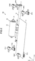
- FIG. 2 is a perspective view illustrating an example of a schematic configuration of the banknote conveying apparatus according to the first embodiment.
- FIG. 2 illustrates a schematic configuration of the banknote conveying apparatus 100 according to the first embodiment, and an illustration of the configuration is omitted as appropriate.
- the banknote conveying apparatus 100 includes a driving roller unit 10, a follower roller unit 20, a pair of check sensors 31LU and 31LL, a pair of check sensors 31RU and 31RL, a pair of position detector sensors 32LU and 32LL, and a pair of position detector sensors 32RU and 32RL.
- the check sensors 31LU, 31LL, 31RU, and 31RL as well as the position detector sensors 32LU, 32LL, 32RU, and 32RL are each fixed at a predetermined position.
- the driving roller unit 10 includes a shaft 11, a roller 12L, and a roller 12R.
- the shaft 11 is pivotally supported by a moving base station 40 in parallel to the X-axis, as will be described later (see FIG. 7 ).
- Each of the rollers 12L and 12R is a conveying roller in the driving roller unit.
- the rollers 12L and 12R are identical rollers, each rotating about the shaft 11 and having an equal diameter.
- the rollers 12L and 12R being spaced with a gap (D1 illustrated in FIG. 2 ) from each other, are axially attached to the shaft 11 and rotate as the shaft 11 rotates.
- the portion between the roller 12L and the roller 12R is smaller in diameter than each of the rollers 12L and 12R.
- rollers 12L and 12R are axially attached to the shaft 11 that moves horizontally in response to the moving base station 40 moving horizontally in positive and negative X-axis directions (hereinafter, will be referred to simply as “horizontally move” or “horizontal movement”). Accordingly, the rollers 12L and 12R horizontally move in response to the shaft 11, while maintaining a mutual positional relationship between the roller 12L and the roller 12R.
- the follower roller unit 20 includes a shaft 21 and a roller 22.
- the roller 22 is a tension roller in the follower roller unit.
- the roller 22 rotates about the shaft 21 and has a rotating diameter equal to the rollers 12L and 12R that both rotate about the shaft 11.
- the roller 22 is axially attached to the shaft 21 in a way that a roller face of the roller 22 is positioned opposite a roller face of each of the rollers 12L and 12R.
- the roller 22 thus rotates as the rollers 12L and 12R rotate.
- the roller 22 is fixed to a frame (not illustrated) so as to be restricted in parallel movement in any direction and be only allowed to rotate about the shaft 21.
- the banknote 2 conveyed on the conveying path 7a as a plane parallel to X-Y plane (see FIG. 1 ) passes a nip section that is formed between the rollers 12L, 12R, and the roller 22.
- the rollers 12L, 12R, and the roller 22 sandwich the banknote 2 therebetween from upper and lower sides in the Z-axis direction. Then, the roller 12L, 12R, and the roller 22 rotate to convey the banknote 2 in the positive Y-axis direction. In this state, the roller 12L, 12R, and the roller 22 convey the banknote 2, and when needed, the rollers 12L and 12R concurrently move horizontally to perform a centering process in which the banknote 2 is horizontally moved to a center in a width direction on the conveying path 7a.
- the banknote 2 sandwiched between the roller 12L, the roller 12R, and the roller 22 is conveyed on the conveying path 7a by friction with the rollers 12L and 12R that horizontally move, while concurrently having its conveyed position corrected to the center in the width direction of the conveying path 7a.
- This configuration corrects the position of the banknote 2 conveyed out of the center in the X-axis direction on the conveying path 7a, so that the banknote 2 is positioned closer to the center in the X-axis direction on the conveying path 7a.
- Each of the pair of check sensors 31LU and 31LL and the pair of check sensors 31RU and 31RL is, for example, a two optical axis photoelectric sensor.
- Each of the pair of check sensors 31LU and 31LL and the pair of check sensors 31RU and 31RL is a set of a light emitting section and a light receiving section.
- Each of the pair of check sensors 31LU and 31LL and the pair of check sensors 31RU and 31RL is disposed in a direction substantially orthogonal to the conveying direction, being spaced from each other with a gap through which the banknote 2 to be stored in the storage unit 6 passes without having its horizontal width blocking between the two optical axes.
- Each of the pair of check sensors 31LU and 31LL and the pair of check sensors 31RU and 31RL is disposed downstream of the driving roller unit 10 and the follower roller unit 20 (i.e., closer to the storage unit 6) on the conveying path 7a.
- a state in which an area between the two optical axes is blocked in each of the pair of check sensors 31LU and 31LL and the pair of check sensors 31RU and 31RL will be referred to simply as a "blocked sensor” state.
- a state in which light transmits between the two optical axes in each of the pair of check sensors 31LU and 31LL and the pair of check sensors 31RU and 31RL will be referred to simply as a "light-transmitting sensor" state.
- the banknote conveying apparatus 100 determines that the banknote 2 is not positioned out of the center toward the positive or negative X-axis direction on the conveying path 7a and is thus conveyed at the center on the conveying path 7a. Accordingly, when the banknote 2 is stored in the storage unit 6, the banknote 2 does not hit a banknote input area of the storage unit 6.
- the banknote conveying apparatus 100 determines, based on the detection result of the check sensors 31LU to 31RL, that the banknote 2 is conveyed at the center on the conveying path 7a, the banknote conveying apparatus 100 does not perform the centering process for the banknote 2. Then, the banknote 2 is conveyed maintaining the current conveyed position on the conveying path 7a to be stored in the storage unit 6.
- the banknote conveying apparatus 100 performing the centering process for the banknote determines, based on the detection result of the check sensors 31LU to 31RL, that the banknote 2 is conveyed at the center on the conveying path 7a, the banknote conveying apparatus 100 terminates execution of the centering process for the banknote 2. Then, the banknote 2 is conveyed maintaining the conveyed position defined at the moment of termination of the execution on the conveying path 7a.
- the banknote conveying apparatus 100 determines that the banknote 2 is conveyed out of the center toward the positive or negative X-axis direction on the conveying path 7a. Accordingly, when the banknote 2 comes to the banknote input area to be stored in the storage unit 6, the banknote 2 hits the banknote input area of the storage unit 6.
- the banknote conveying apparatus 100 determines, based on the detection result of the check sensors 31LU to 31RL, that the banknote 2 is conveyed out of the center in the positive or negative X-axis direction on the conveying path 7a, the banknote conveying apparatus 100 performs the centering process for the banknote 2. In other words, the banknote 2 is conveyed on the conveying path 7a, while concurrently having its conveyed position corrected to the center in the width direction of the conveying path 7a.
- the banknote conveying apparatus 100 determines, based on the detection result of the check sensors 31LU to 31RL, that the banknote 2 is conveyed out of the center toward the positive or negative X-axis direction on the conveying path 7a, the banknote conveying apparatus 100 continues to perform the centering process for the banknote 2.
- the banknote 2 is conveyed on the conveying path 7a, while concurrently and continually having its conveyed position corrected to the center in the width direction of the conveying path 7a.
- the banknote conveying apparatus 100 detects, based on the check sensors 31LU to 31RL, whether or not the banknote 2 is conveyed out of the center toward the positive or negative X-axis direction on the conveying path 7a, while concurrently conveying and executing the centering process for the banknote 2 on the conveying path 7a.
- Each of the pair of position detector sensors 32LU and 32LL and the pair of position detector sensors 32RU and 32RL is, for example, a photoelectric sensor.
- Each of the pair of position detector sensors 32LU and 32LL and the pair of position detector sensors 32RU and 32RL is a set of a light emitting section and a light receiving section.
- Each of the pair of position detector sensors 32LU and 32LL and the pair of position detector sensors 32RU and 32RL is disposed upstream of the driving roller unit 10 and the follower roller unit 20 (i.e., closer to the distinguishing unit 4) on the conveying path 7a.
- a distance between the pair of position detector sensors 32LU and 32LL and the pair of position detector sensors 32RU and 32RL is indicated by L3 (see FIG. 5 ).
- the banknote conveying apparatus 100 determines that the banknote 2 is not positioned out of the center toward the positive or negative X-axis direction and is thus conveyed at the center on the conveying path 7a. In this case, the banknote conveying apparatus 100 does not perform the centering process for the banknote 2 and conveys the banknote 2 maintaining the current position on the conveying path 7a.
- the banknote conveying apparatus 100 determines that the banknote 2 is conveyed out of the center toward the positive or negative X-axis direction on the conveying path 7a.
- the banknote conveying apparatus 100 determines, based on the detection result of the position detector sensors 32LU to 32RL, that the banknote 2 is conveyed out of the center toward the positive or negative X-axis direction on the conveying path 7a, the banknote conveying apparatus 100 performs a preparation for the centering process for the banknote 2.
- the banknote conveying apparatus 100 when needed, moves the rollers 12L and 12R in the driving roller unit 10 from the current position in the X-axis direction to a first home position or a second home position as will be described later.
- the banknote conveying apparatus 100 determines, based on the detection result of the position detector sensors 32LU to 32RL, that the banknote 2 is conveyed out of the center toward the positive (negative) X-axis direction on the conveying path 7a, the banknote conveying apparatus 100 performs the following process. That is to say, when the rollers 12L and 12R are not currently located in a limit position in the positive (negative) X-axis direction, the banknote conveying apparatus 100 moves the rollers 12L and 12R to the limit position in the positive (negative) X-axis direction.
- the limit position in the negative X-axis direction indicates the first home position to be described later.
- the limit position in the positive X-axis direction indicates the second home position to be described later.
- FIG. 3 and FIG. 4 is a plan view illustrating an example of the moving range of the rollers in the driving roller unit in the banknote conveying apparatus according to the first embodiment.
- the moving range of the rollers 12L and 12R in the driving roller unit 10 that horizontally move is equal to a range within which the face of each of the rollers 12L and 12R remains positioned opposite the face of the roller 22 in the follower roller unit 20.
- the roller 12L has an end portion in the negative X-axis direction that aligns in the Z-axis direction with an end portion of the roller 22 in the negative X-axis direction.
- the aligned position is the first home position that represents the moving range limit of the rollers 12L and 12R in the negative X-axis direction.
- the first home position as the moving range limit of the driving roller unit 10 in the negative X-axis direction also represents a home position of the rollers 12L and 12R.
- the roller 12L has an end portion in the positive X-axis direction that aligns in the Z-axis direction with an end portion of the roller 22 in the positive X-axis direction.
- the aligned position is the second home position that represents the moving range limit of the rollers 12L and 12R in the positive X-axis direction.
- the second home position as the moving range limit of the driving roller unit 10 in the positive X-axis direction also represents another home position of the rollers 12L and 12R.
- the driving roller unit 10 horizontally moves in the positive and negative X-axis directions between the first home position and the second home position.
- the rollers 12L and 12R move within the range between the first home position and the second home position in the width direction of the conveying path 7a (X-axis direction) where the roller face of each of the rollers 12L and 12R is positioned opposite the roller face of the roller 22 in a vertical direction of the conveying path 7a (i.e., in a positive Z-axis direction).
- the moving range of the rollers 12L and 12R corresponds to a length range of the roller 22 in the width direction of the conveying path 7a (X-axis direction).
- the predetermined range, within which the rollers 12L and 12R horizontally move is included within a length range of the conveying path 7a of the banknote 2 in the width direction of the conveying path 7a, even when the banknote 2 conveyed on the conveying path 7a is located at any position in width direction of the conveying path 7a.
- the banknote 2 conveyed on the conveying path 7a is caught by the nip section formed between the rollers 12L, 12R, and the roller 22, even when the banknote is positioned out of the center toward anywhere in the width direction on the conveying path 7a. Then, the centering process is performed to correct the position of the banknote 2 to the center on the conveying path 7a.
- the rollers 12L and 12R Before moving in the width direction of the conveying path 7a and concurrently holding the banknote 2 sandwiched between the rollers 12L, 12R, and the roller 22, the rollers 12L and 12R previously move to the limit position closer to where the banknote 2 is conveyed out of the center in the width direction on the conveying path 7a (i.e., the first home position or the second home position). Then, the rollers 12L and 12R move from the limit position as a starting point to move within the predetermined range so as to move the banknote 2 to the center in the width direction on the conveying path 7a. This configuration causes the rollers 12L and 12R to maximize the horizontally movable range to perform the centering process for the banknote 2.
- FIG. 5 is a plan view illustrating a schematic example of the centering process in the banknote conveying apparatus according to the first embodiment.
- the distance L3 between the pair of check sensors 31LU and 31LL and the pair of check sensors 31RU and 31RL is equal to L6 as a width of the banknote input area of the storage unit 6 in the X-direction.
- the banknote 2 has its end portion causing the pair of check sensors 31LU and 31LL to be in the "blocked sensor" state that requests the centering process, and thus, the centering process is performed.
- the driving roller unit 10 moves in a direction A as the positive X-axis direction and in parallel to the X-axis by a first predetermined amount, while concurrently conveying the banknote 2 with the follower roller unit 20 in a direction B as the positive Y-axis direction by a second predetermined amount.
- the banknote 2 has its conveyed position corrected in the X-axis direction so as to be located at a position not to hit the banknote input area of the storage unit 6.
- the banknote 2 is stored in the storage unit 6 without hitting the banknote input area of the storage unit 6.
- the driving roller unit 10 moves in a direction A' as opposite to the direction A and in parallel to the X-axis by the first predetermined amount, while concurrently conveying the banknote 2 with the follower roller unit 20 in the direction B by the second predetermined amount.
- A' + B C' (where each of A' and B is used as a vector).
- FIG. 6 is a plan view illustrating a schematic example of a failure of the centering process in the banknote conveying apparatus according to the first embodiment.
- the banknote 2 has its end portion causing the pair of check sensors 31LU and 31LL to be in the "blocked sensor" state that requests the centering process, and thus, the centering process is performed. Then, for example, the banknote 2 is subjected to the centering process, in which the driving roller unit 10 moves in the positive X-axis direction while concurrently conveying the banknote 2 with the follower roller unit 20 in the positive Y-axis direction.
- the banknote 2 still has its end portion causing the pair of check sensors 31LU and 31LL to be in the "blocked sensor" state.
- the banknote 2 is not moved further in the positive X-direction and is thus not further subjected to the centering process. In this state, the centering process ends in failure.
- the banknote 2 is not recycled but is, for example, accommodated in a collection unit (not illustrated) or in a rejection unit (not illustrated), each including a banknote input area wider than the banknote input area of the storage unit 6, or returned to the depositor.
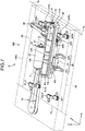
- FIG. 7 and FIG. 8 is a perspective view illustrating an example of the banknote conveying apparatus according to the first embodiment.
- a description of each of FIGS. 7 and 8 a description of each configuration previously described will be omitted.
- the banknote conveying apparatus 100 includes the moving base station 40, a conveying path connection port 50, a home position sensor 60, a horizontal-movement driving mechanism 70, a conveyance-driving mechanism 80, and a housing 100a in addition to the configuration illustrated in FIG. 1 .
- the housing 100a accommodates the driving roller unit 10, the follower roller unit 20, the check sensors 31LU, 31LL, 31RU, and 31RL, the position detector sensors 32LU, 32LL, 32RU, and 32RL, the moving base station 40, the home position sensor 60, the horizontal-movement driving mechanism 70, and the conveyance-driving mechanism 80.
- each of the horizontal-movement driving mechanism 70 and the conveyance-driving mechanism 80 is accommodated at a fixed position and remains fixed regardless of the horizontal movement of the moving base station 40.
- the driving roller unit 10 further includes a gear 13 formed around an outer circumference of the shaft 11.
- the shaft 11 acts as a rotational shaft of the gear 13.
- the shaft 11, the roller 12L and the roller 12R each rotate as the gear 13 rotates.
- the gear 13 has a width L13 in the X-axis direction. The width L13 is equal to or greater than the maximum moving amount in horizontal movement of the moving base station 40 including the rollers 12L and 12R.
- the moving base station 40 includes a pivotal support 41L, a pivotal support 41R, a moving guide hole 42L, a moving guide hole 42R, a guide pin 43L, a guide pin 43R, a sensor shield 44, and a rack 45.
- Each of the pivotal supports 41L and 41R pivotally supports the shaft 11 so that the shaft 11 rotates about its rotational center parallel to the X-axis.
- the moving guide holes 42L and 42R are holes through which the guide pins 43L and 43R are respectively inserted.
- Each of the moving guide holes 42L and 42R has, for example, an oval shape extending by a predetermined length in the X-axis direction.
- Each of the guide pins 43L and 43R is located at a fixed position in the housing 100a. The guide pins 43L and 43R are respectively inserted through the moving guide holes 42L and 42R, so as to allow the moving base station 40 to move only horizontally and to restrict variation in the horizontal moving amount of the moving base station 40.
- the sensor shield 44 is a member attached to extend in a negative Y-axis direction from a part of an edge of the moving base station 40, the edge closer to where the moving guide holes 42L and 42R are located.
- the sensor shield 44 shields the home position sensor 60 (to be described later) so as to detect at which one of the first home position and the second home position the rollers 12L and 12R, moving horizontally in the positive and negative X-axis directions along with the moving base station 40, are positioned.
- the rack 45 is attached to the moving base station 40 on a side opposite to the sensor shield 44, as will be described later with reference to FIG. 8 .
- the rack 45 constitutes a rack and pinion together with a pinion 72b to be described later with reference to FIG. 8 .
- the pinion 72b rotates, the rotation is transmitted to the rack 45 that is tooth-engaged with the pinion 72b, causing the rotation of the pinion 72b to be converted to the horizontal movement of the moving base station 40.
- the conveying path connection port 50 connects the conveying path 7a inside the housing 100a with the conveying path 7a extending out of the housing 100a to the upstream and downstream sides in the banknote conveying apparatus 100 (see FIG. 1 ).
- the banknote 2 passes through the nip section formed between the rollers 12L, 12R, and the roller 22.
- the home position sensor 60 includes a first sensor 61L and a second sensor 61R.
- the first sensor 61L and the second sensor 61R are disposed with a distance from each other, the distance corresponding to a horizontal movement amount allowed for the moving base station 40, in other words, an allowable moving amount when the rollers 12L and 12R horizontally move between the first home position and the second home position.
- Each of the first sensor 61L and the second sensor 61R is, for example, a photoelectric sensor.
- Each of the first sensor 61L and the second sensor 61R having a pair of a light emitting section and a light receiving section, is, for example, a sensor of U-shape facing upward in the positive Z-axis direction.
- the rollers 12L and 12R are positioned at the first home position.
- the rollers 12L and 12R are positioned at the second home position.
- Each of the first sensor 61L and the second sensor 61R is not limited to the one illustrated in the drawings, but may be any sensor or in any shape as long as being a position detector sensor.
- FIG. 8 is a perspective view of the banknote conveying apparatus 100, taken on arrow S in FIG. 7 .
- the horizontal-movement driving mechanism 70 is a mechanism that causes the moving base station 40 including the rollers 12L and 12R to horizontally move.
- the horizontal-movement driving mechanism 70 includes a driving pulley 71, a follower pulley 72a, the pinion 72b, and a driving transmission belt 73.
- the driving pulley 71 acts as a pulley for inputting driving rotation.
- the driving pulley 71 is connected to a driving source (not illustrated) and rotates in response to the driving rotation input from the driving source.
- the control unit 8 controls an operation of the driving source (not illustrated).
- the follower pulley 72a acts as a pulley for rotating in response to the rotation of the driving pulley 71.
- the rotation of the driving pulley 71 is transmitted to the follower pulley 72a via the driving transmission belt 73 that is wound around the driving pulley 71 and wound around the follower pulley 72a.
- the pinion 72b is fixed to the follower pulley 72a and thus rotates as the follower pulley 72a rotates. While omitted in the illustration in FIG. 8 , the pinion 72b includes gear teeth formed on its outer circumferential face.
- the pinion 72b constitutes the rack and pinion together with the rack 45 provided on the moving base station 40.
- the driving pulley 71 rotates, and the rotation is transmitted via a driving transmission belt 73 to the follower pulley 72a.
- the follower pulley 72a rotates, the pinion 72b rotates.
- the rotation is transmitted to the rack 45 tooth-engaged with the pinion 72b, causing the rotation of the pinion 72b to be converted to the horizontal movement of the moving base station 40.
- the moving base station 40 including the rollers 12L and 12R horizontally moves.
- the rotation of the driving pulley 71 is transmitted to the follower pulley 72a via the driving transmission belt 73 (friction transmission), but the transmission manner is not limited thereto.
- a gear or a chain may be used to transmit the rotation.
- the rotation of the pinion 72b is transmitted, and converted via the rack and pinion to the horizontal movement of the moving base station 40, but the conversion manner is not limited thereto.
- the rotation may be converted to the horizontal movement via a friction transmission medium.
- the conveyance-driving mechanism 80 normally operates to convey the banknote 2 from upstream to downstream on the conveying path 7a (in the positive Y-axis direction) whether or not the banknote 2 is horizontally moved.
- the conveyance-driving mechanism 80 includes a driving pulley 81, a follower pulley 82a, a follower gear 82b, a driving transmission gear 83, and a driving transmission belt 84.
- the driving pulley 81 acts as a pulley for inputting driving rotation.
- the driving pulley 81 is connected to the driving source (not illustrated) and rotates in response to the driving rotation input from the driving source.
- the control unit 8 controls the operation of the driving source (not illustrated).
- the follower pulley 82a rotates in response to the rotation of the driving pulley 81.
- the rotation of the driving pulley 81 is transmitted to the follower pulley 82a via the driving transmission belt 84 that is wound around the driving pulley 81 and wound around the follower pulley 82a.
- the follower gear 82b is fixed to the follower pulley 82a and thus rotates as the follower pulley 82a rotates.
- the driving transmission gear 83 rotates and transmits the rotation of the follower gear 82b to the gear 13 of the driving roller unit 10.
- the rotation is transmitted from the follower gear 82b to the driving transmission gear 83 by way of gear transmission. Further, the rotation is transmitted from the driving transmission gear 83 to the gear 13 of the driving roller unit 10 by way of gear transmission.
- the rotation of the driving pulley 81 is transmitted to the follower pulley 82a via the driving transmission belt 73 (friction transmission), but the transmission manner is not limited thereto.
- a gear or a chain may be used to transmit the rotation.
- the rotation is transmitted from the follower gear 82b to the driving transmission gear 83 by way of gear transmission, but the transmission manner is not limited thereto.
- the rotation may be transmitted via a friction transmission medium instead of these gears.
- the rotation is transmitted from the driving transmission gear 83 to the gear 13 of the driving roller unit 10 by way of gear transmission, but the transmission manner is not limited thereto.
- the rotation may be transmitted via a friction transmission medium instead of these gears.
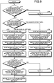
- FIG. 9 is a flowchart illustrating an example of the centering process in the banknote conveying apparatus according to the first embodiment.
- the control unit 8 in the banknote handling apparatus 1 executes the centering process according to the first embodiment at each moment that the banknote 2 passes through the position detector sensors 32LU, 32LL, 32RU, and 32RL.
- Step S11 the control unit 8 determines whether both of the pair of position detector sensors 32LU and 32LL and the pair of position detector sensors 32RU and 32RL detect the "blocked sensor” state or detect the "light-transmitting sensor” state.
- Step S11: Yes the control unit 8 moves on to Step S26.
- Step S11: No the control unit 8 moves on to Step S12.
- Step S12 the control unit 8 determines whether or not one of the pair of position detector sensors 32LU and 32LL and the pair of position detector sensors 32RU and 32RL detects the "blocked sensor" state.
- Step S12: Yes; blocked on the right side the control unit 8 moves on to Step S18.
- Step S12: No; blocked on the left side the control unit 8 moves on to Step S13.
- Step S13 the control unit 8 starts the horizontal movement of the rollers 12L and 12R in a left direction (the negative X-axis direction).
- Step S14 the control unit 8 detects that the horizontal movement of the rollers 12L and 12R in the left direction (negative X-axis direction) causes the first sensor 61L to be in the "blocked sensor" state. In this state, the rollers 12L and 12R are positioned at the first home position.
- Step S15 the control unit 8 detects that the banknote 2 conveyed from upstream to downstream on the conveying path 7a causes the pair of check sensors 31LU and 31LL to be in the "blocked sensor” state.
- Step S16 the control unit 8 starts the horizontal movement of the rollers 12L and 12R together with the banknote 2 from the first home position in a right direction (the positive X-axis direction) so as to start the centering process for the banknote 2.
- Step S17 the control unit 8 continues the horizontal movement of the rollers 12L and 12R from the first home position in the right direction (positive X-axis direction) until the pair of check sensors 31LU and 31LL becomes in the "light-transmitting sensor" state.
- Step S17 completes, the control unit 8 moves on to Step S23.
- Step S18 the control unit 8 starts the horizontal movement of the rollers 12L and 12R in the right direction (positive X-axis direction).
- Step S19 the control unit 8 detects that the horizontal movement of the rollers 12L and 12R in the right direction (positive X-axis direction) causes the second sensor 61R to be in the "blocked sensor" state. In this state, the rollers 12L and 12R are positioned at a second position (the second home position).
- Step S20 the control unit 8 detects that the banknote 2 conveyed from upstream to downstream on the conveying path 7a causes the pair of check sensors 31RU and 31RL to be in the "blocked sensor" state.
- Step S21 the control unit 8 starts the horizontal movement of the rollers 12L and 12R together with the banknote 2 from the second position (first home position) in the left direction (negative X-axis direction) so as to start the centering process for the banknote 2.
- Step S22 the control unit 8 continues the horizontal movement of the rollers 12L and 12R from the second position (second home position) in the left direction (negative X-axis direction) until the pair of check sensors 31RU and 31RL becomes in the "light-transmitting sensor" state.
- Step S22 completes, the control unit 8 moves on to Step S23.
- Step S23 the control unit 8 determines whether or not each of the pair of check sensors 31LU and 31LL and the pair of check sensors 31RU and 31LL has detected the "light-transmitting sensor" state within a specified length of time.
- Step S23: Yes the control unit 8 moves on to Step S26.
- Step S23 determines that one of the pair of check sensors 31LU and 31LL and the pair of check sensors 31RU and 31LL has not detected the "light-transmitting sensor" state within the specified length of time (Step S23: No). the control unit 8 moves on to Step S24.
- Step S24 the control unit 8 determines that the centering process has failed, and thus stores the banknote 2 in the collection unit (not illustrated) or returns the banknote 2 to the depositor.
- Step S25 the control unit 8 returns to Step S11 to execute the process of Step S11 and subsequent steps for each subsequent banknote that is conveyed as the banknote 2.
- Step S26 the control unit 8 determines that the banknote 2 does not request the centering process, and thus stores the banknote 2 in the storage unit 6 to recycle the banknote 2 (use the banknote 2 stored in the storage unit 6 for cash withdrawal).
- Step S26 completes, the control unit 8 moves on to Step S25.
- FIG. 10 is a schematic diagram illustrating an outline of an example in which the centering process is not performed in the banknote conveying apparatus according to the first embodiment.
- the banknote 2 conveyed on the conveying path 7a is smaller in width in the X-axis direction than the storage unit 6 (width: L6), and each of the pair of position detector sensors 32LU and 32LL and the pair of position detector sensors 32RU and 32RL is in the "light-transmitting sensor" state. Accordingly, the centering process for the banknote 2 is not performed.
- This case corresponds to the case in which the determination in Step S11 in FIG. 9 is Yes.
- the conveying path 7a is equal in width in the X-axis direction to the banknote input area of the collection unit (not illustrated).
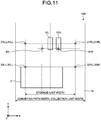
- FIGS. 11 to 14 are schematic diagram illustrating an outline of an example in which the centering process is performed in the banknote conveying apparatus according to the first embodiment.
- FIG. 15 is a schematic diagram illustrating an outline of an example in which the centering process is in an error state in the banknote conveying apparatus according to the first embodiment.
- the banknote 2 conveyed on the conveying path 7a has its left end portion (an end portion in the negative X-axis direction) causing the pair of position detector sensors 32LU and 32LL to be in the "blocked sensor" state. Accordingly, the centering process for the banknote 2 is performed. This case corresponds to the case in which the determination in Step S12 in FIG. 9 is No.
- the banknote 2 conveyed on the conveying path 7a has its left end portion (the end portion in the negative X-axis direction) causing the pair of position detector sensors 32LU and 32LL to be in the "blocked sensor” state.
- the control unit 8 moves the rollers 12L and 12R in the left direction (negative X-axis direction) until the first sensor 61L becomes in the "blocked sensor” state. This case corresponds to Step S13 and Step S14 in FIG. 9 .
- the control unit 8 moves the rollers 12L and 12R in the right direction (positive X-axis direction) until the second sensor 61R becomes in the "blocked sensor” state. (This case corresponds to Step S18 and Step S19 in FIG. 9 .)
- FIG. 13 illustrates a state in which the banknote 2 is further conveyed on the conveying path 7a from the state in the case of FIG. 12 and in which the banknote 2 has its left end portion (the end portion in the negative X-axis direction) causing the pair of check sensors 31LU and 31LL to be in the "blocked sensor" state.
- This moment corresponds to the timing of starting the centering process for the banknote 2 (corresponds to Step S15 in FIG. 9 ).
- the banknote 2 is further conveyed on the conveying path 7a from the state, in which the banknote 2 conveyed on the conveying path 7a has its right end portion (the end portion in the positive X-axis direction) causing the pair of position detector sensors 32RU and 32RL to be in the "blocked sensor” state, and then has its right end portion (the end portion in the positive X-axis direction) causing the pair of check sensors 31RU and 31RL to be in the "blocked sensor” state, the moment corresponds to the timing of starting the centering process for the banknote 2 (corresponds to Step S20 in FIG. 9 ).
- FIG. 14 illustrates a state in which the banknote 2 is further conveyed on the conveying path 7a while being centered from the state in the case of FIG. 13 , and in which the banknote 2 has its left end portion (the end portion in the negative X-axis direction) causing the pair of check sensors 31LU and 31LL to be in the "light-transmitting sensor" state.
- This moment corresponds to the timing of completing the centering process for the banknote 2 (corresponds to Step S16 and Step S17 in FIG. 9 ).
- the banknote 2 is further conveyed on the conveying path 7a from the state, in which the banknote 2 conveyed on the conveying path 7a has its right end portion (the end portion in the positive X-axis direction) causing the pair of check sensors 31LU and 31LL to be in the "blocked sensor” state, and then has its right end portion (the end portion in the positive X-axis direction) causing the pair of check sensors 31LU and 31LL to be in the "light-transmitting sensor” state, the moment corresponds to the timing of completing the centering process for the banknote 2 (corresponds to Step S21 and Step S22 in FIG. 9 ) .
- FIG. 15 illustrates a state in which the banknote 2 is further conveyed on the conveying path 7a while being centered from the state in the case of FIG. 13 , and in which the banknote 2 still has its left end portion (the end portion in the negative X-axis direction) causing the pair of check sensors 31LU and 31LL to be in the "blocked sensor" state even after the specified length of time.
- This state indicates that the centering process for the banknote 2 ends in failure (corresponding to Step S23: No in FIG. 9 ).
- the banknote conveying apparatus 100 having the driving roller unit 10 and the follower roller unit 20 as a pair, monitors via the check sensors 31LU to 31RL whether or not the banknote 2 is conveyed out of the center on the conveying path 7a, and concurrently performs the centering process by only moving the rollers 12L and 12R horizontally.
- the banknote conveying apparatus 100 monitors via the check sensors 31LU to 31RL whether or not the banknote 2 is conveyed out of the center on the conveying path 7a, and concurrently performs the centering process by only moving the rollers 12L and 12R horizontally.
- the control unit 8 moves the rollers 12L and 12R to the limit position in the negative (positive) X-axis direction, i.e., the first home position (second home position).
- the present disclosure is not limited thereto.
- the control unit 8 may determine, based on the detection of the position detector sensors 32LU to 32RL, that the out-of-position amount, which the banknote 2 has from the center of the conveying path 7a, is to be resolved (the banknote 2 is to be centered) only by moving the rollers 12L and 12R horizontally from the current position. In this case, the rollers 12L and 12R may be moved horizontally from the current position without being moved to the limit position. With this configuration, the process of moving the rollers 12L and 12R to each of the home positions may be omitted, thereby resulting in further higher efficiency and higher speed in the centering process.
- the banknote conveying apparatus 100 is disposed downstream of the distinguishing unit 4 as well as upstream of the temporary accommodating unit 5 on the conveying path 7a.
- the banknote conveying apparatus 100 may be disposed at any location from downstream of the distinguishing unit 4 to the storage units 6 on the conveying path 7a.
- the two rollers 12L and 12R being spaced with a predetermined gap from each other, are axially attached to the shaft 11.
- the present disclosure is not limited thereto. Three or more rollers may be spaced with a predetermined gap from one another and axially attached to the shaft 11.
- each of the following sensors is described as a photoelectric sensor: the check sensors 31LU, 31LL, 31RU, and 31RL, the position detector sensors 32LU, 32LL, 32RU, and 32RL, and the sensors of the home position sensor 60.
- the present disclosure is not limited thereto.
- These sensors may be other type of sensors, such as an infrared sensor.
- the banknote conveying apparatus 100 is included in the banknote handling apparatus 1 as a configuration unit of the banknote handling apparatus 1.
- the banknote conveying apparatus 100 may be provided as a unit that is detachable from the banknote handling apparatus 1.
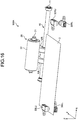
- FIG. 16 is a perspective view illustrating a schematic example of a banknote conveying apparatus according to a second embodiment.
- the check sensors 31LU, 31LL, 31RU, and 31RL are omitted as compared with the banknote conveying apparatus 100 according to the second embodiment.
- the banknote conveying apparatus 100A has a control unit 8A.
- the distinguishing unit 4 distinguishes the banknote 2, and based on the result, the control unit 8A determines at which position in the X-axis direction on the conveying path 7a the banknote 2 is being conveyed. Based on the position determined, the control unit 8A calculates the horizontal movement amount of the rollers 12L and 12R in the centering process for the banknote 2. Then, the control unit 8A horizontally moves the rollers 12L and 12R by the calculated movement amount to perform the centering process for the banknote 2.
- the check sensors 31LU to 31RL are omitted, and the distinguishing result on the banknote 2 by the distinguishing unit 4 is instead used to calculate the horizontal movement amount of the rollers 12L and 12R in the centering process for the banknote 2.
- the centering process for banknote 2 may be efficiently performed.
- FIG. 17 is a perspective view illustrating a schematic example of a banknote conveying apparatus according to a third embodiment.
- a banknote conveying apparatus 100B according to the third embodiment the position detector sensors 32LU, 32LL, 32RU, and 32RL are omitted as compared with the banknote conveying apparatus 100A according to the second embodiment.
- the banknote conveying apparatus 100B has a control unit 8B.
- the distinguishing unit 4 distinguishes the banknote 2, and based on the result, the control unit 8B determines at which position in the X-axis direction on the conveying path 7a the banknote 2 is being conveyed. Based on the position determined, the control unit 8A calculates the horizontal movement amount of the rollers 12L and 12R in the centering process for the banknote 2. Then, the control unit 8A horizontally moves the rollers 12L and 12R by the calculated movement amount to perform the centering process for the banknote 2.
- the control unit 8B determines at which position in the X-axis direction on the conveying path 7a the banknote 2 is being conveyed. Further, based on the position determined, the control unit 8B horizontally moves the rollers 12L and 12R to the first home position or the second home position before performing the centering process for the banknote 2.
- the position detector sensors 32LU and 32LL, and the position detector sensors 32RU and 32RL are also omitted, and the distinguishing result on the banknote 2 by the distinguishing unit 4 is instead used for the preliminary movement of the rollers 12L and 12R to the first home position or the second home position.
- the centering process for banknote 2 may be efficiently performed.
- each of the configurations of the units exemplified in each of the foregoing embodiments may be changed or omitted without departing from the technical scope of a paper sheet conveying apparatus, a paper sheet handling apparatus, and a paper sheet conveying method, each according to the disclosed technique.
- each of the embodiments is mere exemplification, and starting with a mode described in the field of the disclosure of the invention, other modes on which various modifications and improvements are performed based on the knowledge of the one skilled in the art are included in the disclosed technique.
Landscapes
- Engineering & Computer Science (AREA)
- Mechanical Engineering (AREA)
- Registering Or Overturning Sheets (AREA)
- Delivering By Means Of Belts And Rollers (AREA)
- Controlling Sheets Or Webs (AREA)
Abstract
Description
- The present invention relates to a paper sheet conveying apparatus, a paper sheet handling apparatus, and a paper sheet conveying method.
- For example, a banknote handling apparatus, such as an automated teller machine (ATM), a cash dispenser (CD), and a teller cash recycler (TCR), includes a storage unit for storing a banknote deposited. In the banknote handling apparatus, the banknote deposited passes through a distinguishing unit that distinguishes true/false or the like of the banknote, and the banknote is stored in the storage unit that is classified into types of currencies. The banknote deposited in the banknote handling apparatus is typically stored in the storage unit of the same specification according to the types of currencies even when the banknote varies in size according to the types of currencies.
- Here, for example, when a banknote smaller in size than the storage unit is stored and accumulated inside the storage unit, a gap is created between the banknotes accumulated and an inner wall of the storage unit. In some cases, some of the banknotes hang down or fall into the gap, causing the banknotes to be stored out of order in the storage unit. Then, the banknotes stored out of order in the storage unit causes unstable condition for dispensing of the banknotes when the banknotes are withdrawn from the storage unit. For this reason, types of currencies for withdrawal are limited by, for example, excluding the banknotes smaller in size for deposit only.
- In order to prevent the banknotes smaller in size from being stored out of order, a countermeasure is proposed to align an inner size of the storage unit with the size of the banknote. For example, an inner width of the storage unit may be aligned with a width of the banknote that is smaller than a width of a conveying path for the banknote. However, when the banknotes smaller in size are conveyed at an end of the conveying path and about to be stored into the storage unit, some of the banknotes may be stuck against an input area of the storage unit, causing jamming. Under these circumstances, proposed is a related technique that corrects a conveyed position of each of the banknotes in a width direction of the conveying path so as to convey the banknote at a center on the conveying path.
- Patent Document 1: Japanese Laid-open Patent Publication No.
2016-172619 - However, in the related technique described above, the conveying path for the banknote is formed by a pair of upper and lower rollers. The pair of upper and lower rollers is previously slid by an out-of-position amount that the banknote conveyed on the conveying path has from the center in the width direction of the conveying path. When the pair of upper and lower rollers sandwiches the banknote therebetween at the slide position, the pair of upper and lower rollers moves the banknote to the center of the conveying path while holding the banknote sandwiched therebetween. Furthermore, in the related technique, the pair of upper and lower rollers is arranged in plural rows along the conveying direction to form the conveying path. Then, the banknote is handed from one pair to another pair of upper and lower rollers to be moved to the center on the conveyance path. With this configuration, in the related technique, when correcting the conveyed position of the banknote in the width direction on the conveying path, a speed of conveying the banknote may be reduced. Such a problem is not limited to a banknote handling apparatus but may similarly arise in an apparatus that handles paper sheets.
- In view of the respects described above, an object of the present disclosure technique is to provide a paper sheet conveying apparatus, a paper sheet handling apparatus, and a paper sheet conveying method, each configured to correct the position of the banknote conveyed on the conveying path in the width direction of the conveying path, for example, without reducing the speed of conveying the banknote.
- In an example of the disclosed technique, a paper sheet conveying apparatus includes: a driving roller and a follower roller. The driving roller is configured to rotate about a driving roller shaft in response to a rotational force transmitted from a driving source. The follower roller is configured to have a fixed position in a width direction of a conveying path where a paper sheet is conveyed, and rotate about a follower roller shaft in response to rotation of the driving roller while holding the paper sheet sandwiched between the follower roller and the driving roller so as to convey the paper sheet with the driving roller from upstream to downstream on the conveying path. When conveying the paper sheet from upstream to downstream on the conveying path, the driving roller moves in the width direction of the conveying path while holding the paper sheet sandwiched between the driving roller and the driving roller so as to move the paper sheet to a center in the width direction on the conveying path.
- According to an example of the disclosed technique, it is possible to correct a position of a banknote conveyed on a conveying path in a width direction of the conveying path without reducing a speed of conveying the banknote.
-
-
FIG. 1 is a schematic diagram illustrating an example entire side view of a banknote handling apparatus including a banknote conveying apparatus according to a first embodiment. -
FIG. 2 is a perspective view illustrating an example of a schematic configuration of the banknote conveying apparatus according to the first embodiment. -
FIG. 3 is a plan view illustrating an example of a moving range of rollers in a driving roller unit in the banknote conveying apparatus according to the first embodiment. -
FIG. 4 is a plan view illustrating an example of the moving range of the rollers in the driving roller unit in the banknote conveying apparatus according to the first embodiment. -
FIG. 5 is a plan view illustrating a schematic example of a centering process in the banknote conveying apparatus according to the first embodiment. -
FIG. 6 is a plan view illustrating a schematic example of a failure of the centering process in the banknote conveying apparatus according to the first embodiment. -
FIG. 7 is a perspective view illustrating an example of the banknote conveying apparatus according to the first embodiment. -
FIG. 8 is a perspective view illustrating an example of the banknote conveying apparatus according to the first embodiment. -
FIG. 9 is a flowchart illustrating an example of the centering process in the banknote conveying apparatus according to the first embodiment. -
FIG. 10 is a schematic diagram illustrating an outline of an example in which the centering process is not performed in the banknote conveying apparatus according to the first embodiment. -
FIG. 11 is a schematic diagram illustrating an outline of an example in which the centering process is performed in the banknote conveying apparatus according to the first embodiment. -
FIG. 12 is a schematic diagram illustrating an outline of an example in which the centering process is performed in the banknote conveying apparatus according to the first embodiment. -
FIG. 13 is a schematic diagram illustrating an outline of an example in which the centering process is performed in the banknote conveying apparatus according to the first embodiment. -
FIG. 14 is a schematic diagram illustrating an outline of an example in which the centering process is performed in the banknote conveying apparatus according to the first embodiment. -
FIG. 15 is a schematic diagram illustrating an outline of an example in which the centering process is in an error state in the banknote conveying apparatus according to the first embodiment. -
FIG. 16 is a perspective view illustrating a schematic example of a banknote conveying apparatus according to a second embodiment. -
FIG. 17 is a perspective view illustrating a schematic example of a banknote conveying apparatus according to a third embodiment. - Hereinafter, an embodiment of a paper sheet conveying apparatus, a paper sheet handling apparatus, and a paper sheet conveying method, each according to the present disclosure technique, will be described in detail based on the drawings. Note that the paper sheet conveying apparatus, the paper sheet handling apparatus, and the paper sheet conveying method, each according to the present disclosure technique, are not limited to the embodiment described below. The respective elements described in each embodiment and modification below may be combined appropriately as long as no conflict arises.
- In each embodiment below, a banknote is used as an example of a paper sheet, but a paper sheet is not limited thereto. Examples of the paper sheet include valuable securities such as bill, check, a gift ticket, various corporation securities, and stock certificate.
-
FIG. 1 is a schematic diagram illustrating an example entire side view of a banknote handling apparatus including a banknote conveying apparatus according to a first embodiment. As illustrated inFIG. 1 , abanknote handling apparatus 1 according to the embodiment includes a deposit/withdrawal unit 3 for depositing and withdrawing abanknote 2, and a distinguishing unit 4 for distinguishing true/false or the like of thebanknote 2 deposited in the deposit/withdrawal unit 3. Thebanknote handling apparatus 1 also includes atemporary accommodating unit 5 and a plurality ofstorage units 6. Thetemporary accommodating unit 5 takes in thebanknote 2 conveyed from the distinguishing unit 4 and temporarily accommodates thebanknote 2. Each of the plurality ofstorage units 6 stores thebanknote 2 fed from thetemporary accommodating unit 5. - Additionally, the
banknote handling apparatus 1 includes aconveying mechanism 7 for conveying thebanknote 2. Theconveying mechanism 7 includes aconveying path 7a that conveys thebanknote 2 between the deposit/withdrawal unit 3, the distinguishing unit 4, thetemporary accommodating unit 5, and thestorage units 6. Thebanknote handling apparatus 1 includes abanknote conveying apparatus 100 that is positioned between the distinguishing unit 4, thetemporary accommodating unit 5, and thestorage units 6. As with the conveyingmechanism 7, thebanknote conveying apparatus 100 includes the conveyingpath 7a, into which thebanknote 2 is conveyed from the distinguishing unit 4. Thebanknote conveying apparatus 100 corrects a position of thebanknote 2 in an orthogonal direction to a conveying direction on the conveyingpath 7a. Further, thebanknote handling apparatus 1 includes acontrol unit 8 that controls each of the deposit/withdrawal unit 3, the distinguishing unit 4, the temporaryaccommodating unit 5, thestorage units 6, the conveyingmechanism 7, and thebanknote conveying apparatus 100. - In a description of each embodiment below, an orthogonal coordinate system (X, Y, Z) is used as illustrated in
FIG. 1 and subsequent drawings. The orthogonal coordinate system (X, Y, Z) has a Z-axis where a vertical height direction of thebanknote handling apparatus 1 is referred to as a positive direction. The orthogonal coordinate system (X, Y, Z) has a Y-axis that extends from the deposit/withdrawal unit 3 toward the temporaryaccommodating unit 5 in thebanknote handling apparatus 1 as a positive direction and that extends vertically to the Z-axis. The orthogonal coordinate system (X, Y, Z) also has an X-axis that creates a three-dimensional right-handed (positive-oriented) orthogonal coordinate system together with the Y-axis and the Z-axis. However, the orthogonal coordinate system (X, Y, Z) illustrated in each embodiment below merely indicates a relative direction and positional relationship. The orthogonal coordinate system (X, Y, Z) merely indicates the relative positional relationship or direction such as vertical, horizontal, upward, downward, leftward, or rightward. -
FIG. 2 is a perspective view illustrating an example of a schematic configuration of the banknote conveying apparatus according to the first embodiment.FIG. 2 illustrates a schematic configuration of thebanknote conveying apparatus 100 according to the first embodiment, and an illustration of the configuration is omitted as appropriate. - As illustrated in
FIG. 2 , thebanknote conveying apparatus 100 includes a drivingroller unit 10, afollower roller unit 20, a pair of check sensors 31LU and 31LL, a pair of check sensors 31RU and 31RL, a pair of position detector sensors 32LU and 32LL, and a pair of position detector sensors 32RU and 32RL. The check sensors 31LU, 31LL, 31RU, and 31RL as well as the position detector sensors 32LU, 32LL, 32RU, and 32RL are each fixed at a predetermined position. - The driving
roller unit 10 includes ashaft 11, aroller 12L, and aroller 12R. Theshaft 11 is pivotally supported by a movingbase station 40 in parallel to the X-axis, as will be described later (seeFIG. 7 ). Each of therollers rollers shaft 11 and having an equal diameter. Therollers FIG. 2 ) from each other, are axially attached to theshaft 11 and rotate as theshaft 11 rotates. The portion between theroller 12L and theroller 12R is smaller in diameter than each of therollers - The
rollers shaft 11 that moves horizontally in response to the movingbase station 40 moving horizontally in positive and negative X-axis directions (hereinafter, will be referred to simply as "horizontally move" or "horizontal movement"). Accordingly, therollers shaft 11, while maintaining a mutual positional relationship between theroller 12L and theroller 12R. - The
follower roller unit 20 includes ashaft 21 and aroller 22. Theroller 22 is a tension roller in the follower roller unit. Theroller 22 rotates about theshaft 21 and has a rotating diameter equal to therollers shaft 11. - The
roller 22 is axially attached to theshaft 21 in a way that a roller face of theroller 22 is positioned opposite a roller face of each of therollers roller 22 thus rotates as therollers roller 22 is fixed to a frame (not illustrated) so as to be restricted in parallel movement in any direction and be only allowed to rotate about theshaft 21. Thebanknote 2 conveyed on the conveyingpath 7a as a plane parallel to X-Y plane (seeFIG. 1 ) passes a nip section that is formed between therollers roller 22. - When the
banknote 2 is positioned in the nip section, therollers roller 22 sandwich thebanknote 2 therebetween from upper and lower sides in the Z-axis direction. Then, theroller roller 22 rotate to convey thebanknote 2 in the positive Y-axis direction. In this state, theroller roller 22 convey thebanknote 2, and when needed, therollers banknote 2 is horizontally moved to a center in a width direction on the conveyingpath 7a. - In other words, the
banknote 2 sandwiched between theroller 12L, theroller 12R, and theroller 22 is conveyed on the conveyingpath 7a by friction with therollers path 7a. This configuration corrects the position of thebanknote 2 conveyed out of the center in the X-axis direction on the conveyingpath 7a, so that thebanknote 2 is positioned closer to the center in the X-axis direction on the conveyingpath 7a. - When friction coefficient for outer circumferential face of each of the
rollers roller 22 is indicated by µ22, the friction coefficient above is expressed as µ12 > µ22. Accordingly, in the centering process for thebanknote 2, the friction force that therollers banknote 2 contributes more than the friction force that theroller 22 exerts against thebanknote 2. - Each of the pair of check sensors 31LU and 31LL and the pair of check sensors 31RU and 31RL is, for example, a two optical axis photoelectric sensor. Each of the pair of check sensors 31LU and 31LL and the pair of check sensors 31RU and 31RL is a set of a light emitting section and a light receiving section. Each of the pair of check sensors 31LU and 31LL and the pair of check sensors 31RU and 31RL is disposed in a direction substantially orthogonal to the conveying direction, being spaced from each other with a gap through which the
banknote 2 to be stored in thestorage unit 6 passes without having its horizontal width blocking between the two optical axes. Each of the pair of check sensors 31LU and 31LL and the pair of check sensors 31RU and 31RL is disposed downstream of the drivingroller unit 10 and the follower roller unit 20 (i.e., closer to the storage unit 6) on the conveyingpath 7a. - Hereinafter, a state in which an area between the two optical axes is blocked in each of the pair of check sensors 31LU and 31LL and the pair of check sensors 31RU and 31RL will be referred to simply as a "blocked sensor" state. Similarly, a state in which light transmits between the two optical axes in each of the pair of check sensors 31LU and 31LL and the pair of check sensors 31RU and 31RL will be referred to simply as a "light-transmitting sensor" state.
- When both of the pair of check sensors 31LU and 31LL and the pair of check sensors 31RU and 31RL are in the "light-transmitting sensor" state (i.e., light transmits between the light emitting section and the light receiving section), the
banknote conveying apparatus 100 determines that thebanknote 2 is not positioned out of the center toward the positive or negative X-axis direction on the conveyingpath 7a and is thus conveyed at the center on the conveyingpath 7a. Accordingly, when thebanknote 2 is stored in thestorage unit 6, thebanknote 2 does not hit a banknote input area of thestorage unit 6. - In other words, when the
banknote conveying apparatus 100 determines, based on the detection result of the check sensors 31LU to 31RL, that thebanknote 2 is conveyed at the center on the conveyingpath 7a, thebanknote conveying apparatus 100 does not perform the centering process for thebanknote 2. Then, thebanknote 2 is conveyed maintaining the current conveyed position on the conveyingpath 7a to be stored in thestorage unit 6. - When the
banknote conveying apparatus 100 performing the centering process for the banknote determines, based on the detection result of the check sensors 31LU to 31RL, that thebanknote 2 is conveyed at the center on the conveyingpath 7a, thebanknote conveying apparatus 100 terminates execution of the centering process for thebanknote 2. Then, thebanknote 2 is conveyed maintaining the conveyed position defined at the moment of termination of the execution on the conveyingpath 7a. - On the other hand, when one of the pair of check sensors 31LU and 31LL and the pair of check sensors 31RU and 31RL is in the "blocked sensor" state (i.e., the
banknote 2 blocks the area between the light emitting section and the light receiving section), thebanknote conveying apparatus 100 determines that thebanknote 2 is conveyed out of the center toward the positive or negative X-axis direction on the conveyingpath 7a. Accordingly, when thebanknote 2 comes to the banknote input area to be stored in thestorage unit 6, thebanknote 2 hits the banknote input area of thestorage unit 6. - When the
banknote conveying apparatus 100 determines, based on the detection result of the check sensors 31LU to 31RL, that thebanknote 2 is conveyed out of the center in the positive or negative X-axis direction on the conveyingpath 7a, thebanknote conveying apparatus 100 performs the centering process for thebanknote 2. In other words, thebanknote 2 is conveyed on the conveyingpath 7a, while concurrently having its conveyed position corrected to the center in the width direction of the conveyingpath 7a. - As long as the
banknote conveying apparatus 100 determines, based on the detection result of the check sensors 31LU to 31RL, that thebanknote 2 is conveyed out of the center toward the positive or negative X-axis direction on the conveyingpath 7a, thebanknote conveying apparatus 100 continues to perform the centering process for thebanknote 2. In other words, thebanknote 2 is conveyed on the conveyingpath 7a, while concurrently and continually having its conveyed position corrected to the center in the width direction of the conveyingpath 7a. - As has been described above, the
banknote conveying apparatus 100 detects, based on the check sensors 31LU to 31RL, whether or not thebanknote 2 is conveyed out of the center toward the positive or negative X-axis direction on the conveyingpath 7a, while concurrently conveying and executing the centering process for thebanknote 2 on the conveyingpath 7a. - Each of the pair of position detector sensors 32LU and 32LL and the pair of position detector sensors 32RU and 32RL is, for example, a photoelectric sensor. Each of the pair of position detector sensors 32LU and 32LL and the pair of position detector sensors 32RU and 32RL is a set of a light emitting section and a light receiving section. Each of the pair of position detector sensors 32LU and 32LL and the pair of position detector sensors 32RU and 32RL is disposed upstream of the driving
roller unit 10 and the follower roller unit 20 (i.e., closer to the distinguishing unit 4) on the conveyingpath 7a. A distance between the pair of position detector sensors 32LU and 32LL and the pair of position detector sensors 32RU and 32RL is indicated by L3 (seeFIG. 5 ). - When both of the pair of position detector sensors 32LU and 32LL and the pair of position detector sensors 32RU and 32RL are in the "blocked sensor" state (i.e., the
banknote 2 blocks an area between the light emitting section and the light receiving section), thebanknote conveying apparatus 100 determines that thebanknote 2 is not positioned out of the center toward the positive or negative X-axis direction and is thus conveyed at the center on the conveyingpath 7a. In this case, thebanknote conveying apparatus 100 does not perform the centering process for thebanknote 2 and conveys thebanknote 2 maintaining the current position on the conveyingpath 7a. - On the other hand, when one of the pair of position detector sensors 32LU and 32LL and the pair of position detector sensors 32RU and 32RL is in the "blocked sensor" state (i.e., the
banknote 2 blocks the area between the light emitting section and the light receiving section), thebanknote conveying apparatus 100 determines that thebanknote 2 is conveyed out of the center toward the positive or negative X-axis direction on the conveyingpath 7a. When thebanknote conveying apparatus 100 determines, based on the detection result of the position detector sensors 32LU to 32RL, that thebanknote 2 is conveyed out of the center toward the positive or negative X-axis direction on the conveyingpath 7a, thebanknote conveying apparatus 100 performs a preparation for the centering process for thebanknote 2. In other words, thebanknote conveying apparatus 100, when needed, moves therollers roller unit 10 from the current position in the X-axis direction to a first home position or a second home position as will be described later. - When the centering process is performed, the positions of the
rollers rollers - For example, when the
banknote conveying apparatus 100 determines, based on the detection result of the position detector sensors 32LU to 32RL, that thebanknote 2 is conveyed out of the center toward the positive (negative) X-axis direction on the conveyingpath 7a, thebanknote conveying apparatus 100 performs the following process. That is to say, when therollers banknote conveying apparatus 100 moves therollers - Each of
FIG. 3 and FIG. 4 is a plan view illustrating an example of the moving range of the rollers in the driving roller unit in the banknote conveying apparatus according to the first embodiment. The moving range of therollers roller unit 10 that horizontally move is equal to a range within which the face of each of therollers roller 22 in thefollower roller unit 20. - Specifically, as illustrated in
FIG. 3 , theroller 12L has an end portion in the negative X-axis direction that aligns in the Z-axis direction with an end portion of theroller 22 in the negative X-axis direction. The aligned position is the first home position that represents the moving range limit of therollers roller unit 10 in the negative X-axis direction also represents a home position of therollers - Additionally, as illustrated in
FIG. 4 , theroller 12L has an end portion in the positive X-axis direction that aligns in the Z-axis direction with an end portion of theroller 22 in the positive X-axis direction. The aligned position is the second home position that represents the moving range limit of therollers roller unit 10 in the positive X-axis direction also represents another home position of therollers - The driving
roller unit 10 horizontally moves in the positive and negative X-axis directions between the first home position and the second home position. In other words, therollers path 7a (X-axis direction) where the roller face of each of therollers roller 22 in a vertical direction of the conveyingpath 7a (i.e., in a positive Z-axis direction). Here, the moving range of therollers roller 22 in the width direction of the conveyingpath 7a (X-axis direction). - Further, the predetermined range, within which the
rollers path 7a of thebanknote 2 in the width direction of the conveyingpath 7a, even when thebanknote 2 conveyed on the conveyingpath 7a is located at any position in width direction of the conveyingpath 7a. With this configuration, thebanknote 2 conveyed on the conveyingpath 7a is caught by the nip section formed between therollers roller 22, even when the banknote is positioned out of the center toward anywhere in the width direction on the conveyingpath 7a. Then, the centering process is performed to correct the position of thebanknote 2 to the center on the conveyingpath 7a. - Before moving in the width direction of the conveying
path 7a and concurrently holding thebanknote 2 sandwiched between therollers roller 22, therollers banknote 2 is conveyed out of the center in the width direction on the conveyingpath 7a (i.e., the first home position or the second home position). Then, therollers banknote 2 to the center in the width direction on the conveyingpath 7a. This configuration causes therollers banknote 2. -
FIG. 5 is a plan view illustrating a schematic example of the centering process in the banknote conveying apparatus according to the first embodiment. The distance L3 between the pair of check sensors 31LU and 31LL and the pair of check sensors 31RU and 31RL is equal to L6 as a width of the banknote input area of thestorage unit 6 in the X-direction. For example, as illustrated inFIG. 5 , thebanknote 2 has its end portion causing the pair of check sensors 31LU and 31LL to be in the "blocked sensor" state that requests the centering process, and thus, the centering process is performed. - Then, for example, the driving
roller unit 10 moves in a direction A as the positive X-axis direction and in parallel to the X-axis by a first predetermined amount, while concurrently conveying thebanknote 2 with thefollower roller unit 20 in a direction B as the positive Y-axis direction by a second predetermined amount. With this configuration, thebanknote 2 is subjected to the centering process based on the moving amount and direction expressed by A + B = C (where each of A and B is used as a vector). As a result, thebanknote 2 has its conveyed position corrected in the X-axis direction so as to be located at a position not to hit the banknote input area of thestorage unit 6. Subsequently, thebanknote 2 is stored in thestorage unit 6 without hitting the banknote input area of thestorage unit 6. - When the
banknote 2 has its end portion causing the pair of check sensors 31RU and 31RL to be in the "blocked sensor" state that requests the centering process, the drivingroller unit 10 moves in a direction A' as opposite to the direction A and in parallel to the X-axis by the first predetermined amount, while concurrently conveying thebanknote 2 with thefollower roller unit 20 in the direction B by the second predetermined amount. With this configuration, thebanknote 2 is subjected to the centering process based on the moving amount and direction expressed by A' + B = C' (where each of A' and B is used as a vector). -
FIG. 6 is a plan view illustrating a schematic example of a failure of the centering process in the banknote conveying apparatus according to the first embodiment. For example, as illustrated inFIG. 6 , thebanknote 2 has its end portion causing the pair of check sensors 31LU and 31LL to be in the "blocked sensor" state that requests the centering process, and thus, the centering process is performed. Then, for example, thebanknote 2 is subjected to the centering process, in which the drivingroller unit 10 moves in the positive X-axis direction while concurrently conveying thebanknote 2 with thefollower roller unit 20 in the positive Y-axis direction. - However, even when the driving
roller unit 10 reaches the second home position in the positive X-axis direction, thebanknote 2 still has its end portion causing the pair of check sensors 31LU and 31LL to be in the "blocked sensor" state. Thebanknote 2 is not moved further in the positive X-direction and is thus not further subjected to the centering process. In this state, the centering process ends in failure. In this case, thebanknote 2 is not recycled but is, for example, accommodated in a collection unit (not illustrated) or in a rejection unit (not illustrated), each including a banknote input area wider than the banknote input area of thestorage unit 6, or returned to the depositor. - Each of
FIG. 7 andFIG. 8 is a perspective view illustrating an example of the banknote conveying apparatus according to the first embodiment. In a description of each ofFIGS. 7 and8 , a description of each configuration previously described will be omitted. - The
banknote conveying apparatus 100 according to the first embodiment includes the movingbase station 40, a conveyingpath connection port 50, ahome position sensor 60, a horizontal-movement driving mechanism 70, a conveyance-drivingmechanism 80, and ahousing 100a in addition to the configuration illustrated inFIG. 1 . - The
housing 100a accommodates the drivingroller unit 10, thefollower roller unit 20, the check sensors 31LU, 31LL, 31RU, and 31RL, the position detector sensors 32LU, 32LL, 32RU, and 32RL, the movingbase station 40, thehome position sensor 60, the horizontal-movement driving mechanism 70, and the conveyance-drivingmechanism 80. - In the
housing 100a, each of the horizontal-movement driving mechanism 70 and the conveyance-drivingmechanism 80 is accommodated at a fixed position and remains fixed regardless of the horizontal movement of the movingbase station 40. - The driving
roller unit 10 further includes agear 13 formed around an outer circumference of theshaft 11. Theshaft 11 acts as a rotational shaft of thegear 13. In the drivingroller unit 10, theshaft 11, theroller 12L and theroller 12R each rotate as thegear 13 rotates. Thegear 13 has a width L13 in the X-axis direction. The width L13 is equal to or greater than the maximum moving amount in horizontal movement of the movingbase station 40 including therollers - The moving
base station 40 includes apivotal support 41L, apivotal support 41R, a movingguide hole 42L, a movingguide hole 42R, aguide pin 43L, aguide pin 43R, asensor shield 44, and arack 45. Each of thepivotal supports shaft 11 so that theshaft 11 rotates about its rotational center parallel to the X-axis. The movingguide holes - Each of the moving
guide holes housing 100a. The guide pins 43L and 43R are respectively inserted through the movingguide holes base station 40 to move only horizontally and to restrict variation in the horizontal moving amount of the movingbase station 40. - The
sensor shield 44 is a member attached to extend in a negative Y-axis direction from a part of an edge of the movingbase station 40, the edge closer to where the movingguide holes sensor shield 44 shields the home position sensor 60 (to be described later) so as to detect at which one of the first home position and the second home position therollers base station 40, are positioned. - The
rack 45 is attached to the movingbase station 40 on a side opposite to thesensor shield 44, as will be described later with reference toFIG. 8 . Therack 45 constitutes a rack and pinion together with apinion 72b to be described later with reference toFIG. 8 . When thepinion 72b rotates, the rotation is transmitted to therack 45 that is tooth-engaged with thepinion 72b, causing the rotation of thepinion 72b to be converted to the horizontal movement of the movingbase station 40. - The conveying
path connection port 50 connects the conveyingpath 7a inside thehousing 100a with the conveyingpath 7a extending out of thehousing 100a to the upstream and downstream sides in the banknote conveying apparatus 100 (seeFIG. 1 ). On the conveyingpath 7a inside thehousing 100a, thebanknote 2 passes through the nip section formed between therollers roller 22. - The
home position sensor 60 includes afirst sensor 61L and asecond sensor 61R. Thefirst sensor 61L and thesecond sensor 61R are disposed with a distance from each other, the distance corresponding to a horizontal movement amount allowed for the movingbase station 40, in other words, an allowable moving amount when therollers first sensor 61L and thesecond sensor 61R is, for example, a photoelectric sensor. - Each of the
first sensor 61L and thesecond sensor 61R, having a pair of a light emitting section and a light receiving section, is, for example, a sensor of U-shape facing upward in the positive Z-axis direction. When the movingbase station 40 horizontally moves in the negative X-axis direction, causing thesensor shield 44 to shield thefirst sensor 61L, therollers base station 40 horizontally moves in the positive X-axis direction, causing thesensor shield 44 to shield thesecond sensor 61R, therollers - Each of the
first sensor 61L and thesecond sensor 61R is not limited to the one illustrated in the drawings, but may be any sensor or in any shape as long as being a position detector sensor. - The horizontal-
movement driving mechanism 70 and the conveyance-drivingmechanism 80 will be described with reference toFIG. 8. FIG. 8 is a perspective view of thebanknote conveying apparatus 100, taken on arrow S inFIG. 7 . - The horizontal-
movement driving mechanism 70 is a mechanism that causes the movingbase station 40 including therollers movement driving mechanism 70 includes a drivingpulley 71, afollower pulley 72a, thepinion 72b, and a drivingtransmission belt 73. - The driving
pulley 71 acts as a pulley for inputting driving rotation. The drivingpulley 71 is connected to a driving source (not illustrated) and rotates in response to the driving rotation input from the driving source. The control unit 8 (seeFIG. 1 ) controls an operation of the driving source (not illustrated). - The
follower pulley 72a acts as a pulley for rotating in response to the rotation of the drivingpulley 71. The rotation of the drivingpulley 71 is transmitted to thefollower pulley 72a via the drivingtransmission belt 73 that is wound around the drivingpulley 71 and wound around thefollower pulley 72a. Thepinion 72b is fixed to thefollower pulley 72a and thus rotates as thefollower pulley 72a rotates. While omitted in the illustration inFIG. 8 , thepinion 72b includes gear teeth formed on its outer circumferential face. - As previously described, the
pinion 72b constitutes the rack and pinion together with therack 45 provided on the movingbase station 40. The drivingpulley 71 rotates, and the rotation is transmitted via a drivingtransmission belt 73 to thefollower pulley 72a. As thefollower pulley 72a rotates, thepinion 72b rotates. When thepinion 72b rotates, the rotation is transmitted to therack 45 tooth-engaged with thepinion 72b, causing the rotation of thepinion 72b to be converted to the horizontal movement of the movingbase station 40. As a result, the movingbase station 40 including therollers - Here, the rotation of the driving
pulley 71 is transmitted to thefollower pulley 72a via the driving transmission belt 73 (friction transmission), but the transmission manner is not limited thereto. Instead of these pulleys, a gear or a chain may be used to transmit the rotation. Additionally, here, the rotation of thepinion 72b is transmitted, and converted via the rack and pinion to the horizontal movement of the movingbase station 40, but the conversion manner is not limited thereto. The rotation may be converted to the horizontal movement via a friction transmission medium. - The conveyance-driving
mechanism 80 normally operates to convey thebanknote 2 from upstream to downstream on the conveyingpath 7a (in the positive Y-axis direction) whether or not thebanknote 2 is horizontally moved. The conveyance-drivingmechanism 80 includes a drivingpulley 81, afollower pulley 82a, afollower gear 82b, a drivingtransmission gear 83, and a drivingtransmission belt 84. - The driving
pulley 81 acts as a pulley for inputting driving rotation. The drivingpulley 81 is connected to the driving source (not illustrated) and rotates in response to the driving rotation input from the driving source. The control unit 8 (seeFIG. 1 ) controls the operation of the driving source (not illustrated). - The
follower pulley 82a rotates in response to the rotation of the drivingpulley 81. The rotation of the drivingpulley 81 is transmitted to thefollower pulley 82a via the drivingtransmission belt 84 that is wound around the drivingpulley 81 and wound around thefollower pulley 82a. Thefollower gear 82b is fixed to thefollower pulley 82a and thus rotates as thefollower pulley 82a rotates. When thefollower gear 82b rotates, the drivingtransmission gear 83 rotates and transmits the rotation of thefollower gear 82b to thegear 13 of the drivingroller unit 10. - The rotation is transmitted from the
follower gear 82b to the drivingtransmission gear 83 by way of gear transmission. Further, the rotation is transmitted from the drivingtransmission gear 83 to thegear 13 of the drivingroller unit 10 by way of gear transmission. - Here, the rotation of the driving
pulley 81 is transmitted to thefollower pulley 82a via the driving transmission belt 73 (friction transmission), but the transmission manner is not limited thereto. Instead of these pulleys, a gear or a chain may be used to transmit the rotation. Additionally, here, the rotation is transmitted from thefollower gear 82b to the drivingtransmission gear 83 by way of gear transmission, but the transmission manner is not limited thereto. The rotation may be transmitted via a friction transmission medium instead of these gears. Further, the rotation is transmitted from the drivingtransmission gear 83 to thegear 13 of the drivingroller unit 10 by way of gear transmission, but the transmission manner is not limited thereto. The rotation may be transmitted via a friction transmission medium instead of these gears. -
FIG. 9 is a flowchart illustrating an example of the centering process in the banknote conveying apparatus according to the first embodiment. Thecontrol unit 8 in thebanknote handling apparatus 1 executes the centering process according to the first embodiment at each moment that thebanknote 2 passes through the position detector sensors 32LU, 32LL, 32RU, and 32RL. - First, in Step S11, the
control unit 8 determines whether both of the pair of position detector sensors 32LU and 32LL and the pair of position detector sensors 32RU and 32RL detect the "blocked sensor" state or detect the "light-transmitting sensor" state. When thecontrol unit 8 determines that both of the pair of position detector sensors 32LU and 32LL and the pair of position detector sensors 32RU and 32RL detect the "blocked sensor" state (Step S11: Yes), thecontrol unit 8 moves on to Step S26. On the other hand, when thecontrol unit 8 determines that one of the pair of position detector sensors 32LU and 32LL and the pair of position detector sensors 32RU and 32RL detects the "blocked sensor" state (Step S11: No), thecontrol unit 8 moves on to Step S12. - In Step S12, the
control unit 8 determines whether or not one of the pair of position detector sensors 32LU and 32LL and the pair of position detector sensors 32RU and 32RL detects the "blocked sensor" state. When thecontrol unit 8 determines that the pair of position detector sensors 32RU and 32RL detects the blocked sensor" state (Step S12: Yes; blocked on the right side), thecontrol unit 8 moves on to Step S18. On the other hand, when thecontrol unit 8 determines that the pair of position detector sensors 32LU and 32LL detects the "blocked sensor" state (Step S12: No; blocked on the left side), thecontrol unit 8 moves on to Step S13. - In Step S13, the
control unit 8 starts the horizontal movement of therollers control unit 8 detects that the horizontal movement of therollers first sensor 61L to be in the "blocked sensor" state. In this state, therollers - Next, in Step S15, the
control unit 8 detects that thebanknote 2 conveyed from upstream to downstream on the conveyingpath 7a causes the pair of check sensors 31LU and 31LL to be in the "blocked sensor" state. In Step S16, thecontrol unit 8 starts the horizontal movement of therollers banknote 2 from the first home position in a right direction (the positive X-axis direction) so as to start the centering process for thebanknote 2. - In Step S17, the
control unit 8 continues the horizontal movement of therollers control unit 8 moves on to Step S23. - On the other hand, in Step S18, the
control unit 8 starts the horizontal movement of therollers control unit 8 detects that the horizontal movement of therollers second sensor 61R to be in the "blocked sensor" state. In this state, therollers - Next, in Step S20, the
control unit 8 detects that thebanknote 2 conveyed from upstream to downstream on the conveyingpath 7a causes the pair of check sensors 31RU and 31RL to be in the "blocked sensor" state. In Step S21, thecontrol unit 8 starts the horizontal movement of therollers banknote 2 from the second position (first home position) in the left direction (negative X-axis direction) so as to start the centering process for thebanknote 2. - In Step S22, the
control unit 8 continues the horizontal movement of therollers control unit 8 moves on to Step S23. - In Step S23, the
control unit 8 determines whether or not each of the pair of check sensors 31LU and 31LL and the pair of check sensors 31RU and 31LL has detected the "light-transmitting sensor" state within a specified length of time. When thecontrol unit 8 determines that each of the pair of check sensors 31LU and 31LL and the pair of check sensors 31RU and 31LL has detected the "light-transmitting sensor" state within the specified length of time (Step S23: Yes), thecontrol unit 8 moves on to Step S26. On the other hand, when thecontrol unit 8 determines that one of the pair of check sensors 31LU and 31LL and the pair of check sensors 31RU and 31LL has not detected the "light-transmitting sensor" state within the specified length of time (Step S23: No), thecontrol unit 8 moves on to Step S24. - In Step S24, the
control unit 8 determines that the centering process has failed, and thus stores thebanknote 2 in the collection unit (not illustrated) or returns thebanknote 2 to the depositor. After Step S24, in Step S25, thecontrol unit 8 returns to Step S11 to execute the process of Step S11 and subsequent steps for each subsequent banknote that is conveyed as thebanknote 2. - On the other hand, in Step S26, the
control unit 8 determines that thebanknote 2 does not request the centering process, and thus stores thebanknote 2 in thestorage unit 6 to recycle the banknote 2 (use thebanknote 2 stored in thestorage unit 6 for cash withdrawal). When Step S26 completes, thecontrol unit 8 moves on to Step S25. -
FIG. 10 is a schematic diagram illustrating an outline of an example in which the centering process is not performed in the banknote conveying apparatus according to the first embodiment. In a case illustrated inFIG. 10 , thebanknote 2 conveyed on the conveyingpath 7a is smaller in width in the X-axis direction than the storage unit 6 (width: L6), and each of the pair of position detector sensors 32LU and 32LL and the pair of position detector sensors 32RU and 32RL is in the "light-transmitting sensor" state. Accordingly, the centering process for thebanknote 2 is not performed. This case corresponds to the case in which the determination in Step S11 inFIG. 9 is Yes. Note that, as illustrated inFIGS. 10 to 15 , the conveyingpath 7a is equal in width in the X-axis direction to the banknote input area of the collection unit (not illustrated). - Each of
FIGS. 11 to 14 is a schematic diagram illustrating an outline of an example in which the centering process is performed in the banknote conveying apparatus according to the first embodiment.FIG. 15 is a schematic diagram illustrating an outline of an example in which the centering process is in an error state in the banknote conveying apparatus according to the first embodiment. In a case illustrated inFIG. 11 , thebanknote 2 conveyed on the conveyingpath 7a has its left end portion (an end portion in the negative X-axis direction) causing the pair of position detector sensors 32LU and 32LL to be in the "blocked sensor" state. Accordingly, the centering process for thebanknote 2 is performed. This case corresponds to the case in which the determination in Step S12 inFIG. 9 is No. Similarly, when thebanknote 2 conveyed on the conveyingpath 7a has its right end portion (an end portion in the positive X-axis direction) causing the pair of position detector sensors 32RU and 32RL to be in the "blocked sensor" state, the centering process for thebanknote 2 is performed. - In a case illustrated in
FIG. 12 , thebanknote 2 conveyed on the conveyingpath 7a (as illustrated inFIG. 11 ) has its left end portion (the end portion in the negative X-axis direction) causing the pair of position detector sensors 32LU and 32LL to be in the "blocked sensor" state. Thus, in order to execute the centering process for thebanknote 2, thecontrol unit 8 moves therollers first sensor 61L becomes in the "blocked sensor" state. This case corresponds to Step S13 and Step S14 inFIG. 9 . Similarly, when thebanknote 2 conveyed on the conveyingpath 7a has its right end portion (the end portion in the positive X-axis direction) causing the pair of position detector sensors 32RU and 32RL to be in the "blocked sensor" state, in order to execute the centering process for thebanknote 2, thecontrol unit 8 moves therollers second sensor 61R becomes in the "blocked sensor" state. (This case corresponds to Step S18 and Step S19 inFIG. 9 .) -
FIG. 13 illustrates a state in which thebanknote 2 is further conveyed on the conveyingpath 7a from the state in the case ofFIG. 12 and in which thebanknote 2 has its left end portion (the end portion in the negative X-axis direction) causing the pair of check sensors 31LU and 31LL to be in the "blocked sensor" state. This moment corresponds to the timing of starting the centering process for the banknote 2 (corresponds to Step S15 inFIG. 9 ). Similarly, when thebanknote 2 is further conveyed on the conveyingpath 7a from the state, in which thebanknote 2 conveyed on the conveyingpath 7a has its right end portion (the end portion in the positive X-axis direction) causing the pair of position detector sensors 32RU and 32RL to be in the "blocked sensor" state, and then has its right end portion (the end portion in the positive X-axis direction) causing the pair of check sensors 31RU and 31RL to be in the "blocked sensor" state, the moment corresponds to the timing of starting the centering process for the banknote 2 (corresponds to Step S20 inFIG. 9 ). -
FIG. 14 illustrates a state in which thebanknote 2 is further conveyed on the conveyingpath 7a while being centered from the state in the case ofFIG. 13 , and in which thebanknote 2 has its left end portion (the end portion in the negative X-axis direction) causing the pair of check sensors 31LU and 31LL to be in the "light-transmitting sensor" state. This moment corresponds to the timing of completing the centering process for the banknote 2 (corresponds to Step S16 and Step S17 inFIG. 9 ). Similarly, when thebanknote 2 is further conveyed on the conveyingpath 7a from the state, in which thebanknote 2 conveyed on the conveyingpath 7a has its right end portion (the end portion in the positive X-axis direction) causing the pair of check sensors 31LU and 31LL to be in the "blocked sensor" state, and then has its right end portion (the end portion in the positive X-axis direction) causing the pair of check sensors 31LU and 31LL to be in the "light-transmitting sensor" state, the moment corresponds to the timing of completing the centering process for the banknote 2 (corresponds to Step S21 and Step S22 inFIG. 9 ) . -
FIG. 15 illustrates a state in which thebanknote 2 is further conveyed on the conveyingpath 7a while being centered from the state in the case ofFIG. 13 , and in which thebanknote 2 still has its left end portion (the end portion in the negative X-axis direction) causing the pair of check sensors 31LU and 31LL to be in the "blocked sensor" state even after the specified length of time. This state indicates that the centering process for thebanknote 2 ends in failure (corresponding to Step S23: No inFIG. 9 ). Similarly, when thebanknote 2 is further conveyed on the conveyingpath 7a from the state, in which thebanknote 2 conveyed on the conveyingpath 7a has its right end portion (the end portion in the positive X-axis direction) causing the pair of check sensors 31LU and 31LL to be in the "blocked sensor" state, but even after the specified length of time, thebanknote 2 still has its right end portion (the end portion in the positive X-axis direction) causing the pair of check sensors 31LU and 31LL to be in the "blocked sensor" state, the state indicates that the centering process for thebanknote 2 ends in failure (corresponding to Step S23: No inFIG. 9 ). - According to the first embodiment described above, the
banknote conveying apparatus 100, having the drivingroller unit 10 and thefollower roller unit 20 as a pair, monitors via the check sensors 31LU to 31RL whether or not thebanknote 2 is conveyed out of the center on the conveyingpath 7a, and concurrently performs the centering process by only moving therollers banknote 2 efficiently without reducing speed of conveying thebanknote 2. According to the first embodiment, it is also possible to prevent thebanknote 2 from being stored out of order in thestorage unit 6 or from jamming against the input area of thestorage unit 6. Further, according to the first embodiment, when thebanknote 2 smaller in size is withdrawn from thestorage unit 6, the process is performed in a more stable manner. - In the first embodiment, when the
rollers banknote 2 on the conveyingpath 7a takes place, thecontrol unit 8 moves therollers rollers banknote 2 takes place, thecontrol unit 8 may determine, based on the detection of the position detector sensors 32LU to 32RL, that the out-of-position amount, which thebanknote 2 has from the center of the conveyingpath 7a, is to be resolved (thebanknote 2 is to be centered) only by moving therollers rollers rollers - In the first embodiment, the
banknote conveying apparatus 100 is disposed downstream of the distinguishing unit 4 as well as upstream of the temporaryaccommodating unit 5 on the conveyingpath 7a. However, the present disclosure is not limited thereto. Thebanknote conveying apparatus 100 may be disposed at any location from downstream of the distinguishing unit 4 to thestorage units 6 on the conveyingpath 7a. - In the first embodiment, the two
rollers shaft 11. However, the present disclosure is not limited thereto. Three or more rollers may be spaced with a predetermined gap from one another and axially attached to theshaft 11. - In the first embodiment, each of the following sensors is described as a photoelectric sensor: the check sensors 31LU, 31LL, 31RU, and 31RL, the position detector sensors 32LU, 32LL, 32RU, and 32RL, and the sensors of the
home position sensor 60. However, the present disclosure is not limited thereto. These sensors may be other type of sensors, such as an infrared sensor. - In the first embodiment, the
banknote conveying apparatus 100 is included in thebanknote handling apparatus 1 as a configuration unit of thebanknote handling apparatus 1. However, the present disclosure is not limited thereto. Thebanknote conveying apparatus 100 may be provided as a unit that is detachable from thebanknote handling apparatus 1. -
FIG. 16 is a perspective view illustrating a schematic example of a banknote conveying apparatus according to a second embodiment. In abanknote conveying apparatus 100A according to the second embodiment, the check sensors 31LU, 31LL, 31RU, and 31RL are omitted as compared with thebanknote conveying apparatus 100 according to the second embodiment. - The
banknote conveying apparatus 100A according to the second embodiment has a control unit 8A. The distinguishing unit 4 distinguishes thebanknote 2, and based on the result, the control unit 8A determines at which position in the X-axis direction on the conveyingpath 7a thebanknote 2 is being conveyed. Based on the position determined, the control unit 8A calculates the horizontal movement amount of therollers banknote 2. Then, the control unit 8A horizontally moves therollers banknote 2. - According to the second embodiment, the check sensors 31LU to 31RL are omitted, and the distinguishing result on the
banknote 2 by the distinguishing unit 4 is instead used to calculate the horizontal movement amount of therollers banknote 2. Thus, according to the second embodiment, with the further simplified configuration and the further simplified process, the centering process forbanknote 2 may be efficiently performed. -
FIG. 17 is a perspective view illustrating a schematic example of a banknote conveying apparatus according to a third embodiment. In abanknote conveying apparatus 100B according to the third embodiment, the position detector sensors 32LU, 32LL, 32RU, and 32RL are omitted as compared with thebanknote conveying apparatus 100A according to the second embodiment. - The
banknote conveying apparatus 100B according to the third embodiment has a control unit 8B. The distinguishing unit 4 distinguishes thebanknote 2, and based on the result, the control unit 8B determines at which position in the X-axis direction on the conveyingpath 7a thebanknote 2 is being conveyed. Based on the position determined, the control unit 8A calculates the horizontal movement amount of therollers banknote 2. Then, the control unit 8A horizontally moves therollers banknote 2. - Based on the distinguishing result on the
banknote 2 by the distinguishing unit 4, the control unit 8B determines at which position in the X-axis direction on the conveyingpath 7a thebanknote 2 is being conveyed. Further, based on the position determined, the control unit 8B horizontally moves therollers banknote 2. - According to the third embodiment, the position detector sensors 32LU and 32LL, and the position detector sensors 32RU and 32RL are also omitted, and the distinguishing result on the
banknote 2 by the distinguishing unit 4 is instead used for the preliminary movement of therollers banknote 2 may be efficiently performed. - Each of the configurations of the units exemplified in each of the foregoing embodiments may be changed or omitted without departing from the technical scope of a paper sheet conveying apparatus, a paper sheet handling apparatus, and a paper sheet conveying method, each according to the disclosed technique. In addition, each of the embodiments is mere exemplification, and starting with a mode described in the field of the disclosure of the invention, other modes on which various modifications and improvements are performed based on the knowledge of the one skilled in the art are included in the disclosed technique.
-
- 1
- BANKNOTE HANDLING APPARATUS
- 2
- BANKNOTE
- 3
- DEPOSIT/WITHDRAWAL UNIT
- 4
- DISTINGUISHING UNIT
- 5
- TEMPORARY ACCOMMODATING UNIT
- 6
- STORAGE UNIT
- 7
- CONVEYING MECHANISM
- 7a
- CONVEYING PATH
- 8, 8A, 8B
- CONTROL UNIT
- 10
- DRIVING ROLLER UNIT
- 11
- SHAFT
- 12L, 12R
- ROLLER
- 13
- GEAR
- 20
- FOLLOWER ROLLER UNIT
- 21
- SHAFT
- 22
- ROLLER
- 31LU, 31LL, 31RU, 31RL
- CHECK SENSOR
- 32LU, 32LL, 32RU, 32RL
- POSITION DETECTOR SENSOR
- 40
- MOVING BASE STATION
- 41L, 41R
- PIVOTAL SUPPORT
- 42L, 42R
- MOVING GUIDE HOLE
- 43L, 43R
- GUIDE PIN
- 44
- SENSOR SHIELD
- 45
- RACK
- 50
- CONVEYING PATH CONNECTION PORT
- 60
- HOME POSITION SENSOR
- 61L
- FIRST SENSOR
- 61R
- SECOND SENSOR
- 70
- HORIZONTAL-MOVEMENT DRIVING MECHANISM
- 71
- DRIVING PULLEY
- 72a
- FOLLOWER PULLEY
- 72b
- PINION
- 73
- DRIVING TRANSMISSION BELT
- 80
- CONVEYANCE-DRIVING MECHANISM
- 81
- DRIVING PULLEY
- 82a
- FOLLOWER PULLEY
- 82b
- FOLLOWER GEAR
- 83
- DRIVING TRANSMISSION GEAR
- 84
- DRIVING TRANSMISSION BELT
- 100, 100A, 100B
- BANKNOTE CONVEYING APPARATUS
- 100a
- HOUSING
Claims (8)
- A paper sheet conveying apparatus comprising:a driving roller configured to rotate about a driving roller shaft in response to a rotational force transmitted from a driving source; anda follower roller configured to have a fixed position in a width direction of a conveying path where a paper sheet is conveyed, and rotate about a follower roller shaft in response to rotation of the driving roller while holding the paper sheet sandwiched between the follower roller and the driving roller so as to convey the paper sheet with the driving roller from upstream to downstream on the conveying path, whereinwhen conveying the paper sheet from upstream to downstream on the conveying path, the driving roller moves in the width direction of the conveying path while holding the paper sheet sandwiched between the driving roller and the driving roller so as to move the paper sheet to a center in the width direction on the conveying path.
- The paper sheet conveying apparatus according to claim 1, wherein the driving roller includes a plurality of rollers that are axially attached to the driving roller shaft and are spaced with a predetermined gap from each other on the driving roller shaft.
- The paper sheet conveying apparatus according to claim 1, wherein the driving roller moves within a predetermined range in the width direction of the conveying path, the predetermined range within which a face of the driving roller is positioned opposite a face of the follower roller.
- The paper sheet conveying apparatus according to claim 3, wherein the predetermined range in the width direction of the conveying path is included within a length range of the paper sheet in the width direction of the conveying path, even when the paper sheet conveyed on the conveying path is located at any position in the width direction of the conveying path.
- The paper sheet conveying apparatus according to claim 3, wherein before holding the paper sheet sandwiched between the driving roller and the driving roller and concurrently moving in the width direction of the conveying path, the driving roller previously moves to a limit position of the predetermined range closer to where the paper sheet conveyed on the conveying path is positioned out of the center in the width direction of the conveying path, and when moving the paper sheet to the center in the width direction on the conveying path, the driving roller moves from the limit position as a starting point to move within the predetermined range.
- The paper sheet conveying apparatus according to claim 1, further including
a detector unit configured to detect that the paper sheet conveyed on the conveying path is positioned out of the center in the width direction of the conveying path, wherein
the driving roller moves in the width direction of the conveying path while holding the paper sheet sandwiched between the driving roller and the driving roller until the detector unit detects that the paper sheet conveyed on the conveying path, having been detected to be positioned out of the center in the width direction of the conveying path, is no longer conveyed out of the center in the width direction on the conveying path. - A paper sheet handling apparatus comprising:the paper sheet conveying apparatus according to any one of claims 1 to 6;an input/output unit configured to be used to put in or take out a paper sheet;a distinguishing unit configured to distinguish the paper sheet put in from the input/output unit;a storage unit configured to store the paper sheet;a conveying mechanism including a conveying path configured to mutually connect the input/output unit, the distinguishing unit, the paper sheet conveying apparatus, and the storage unit with one another to convey the paper sheet in dual directions; anda control unit configured to control the paper sheet conveying apparatus and the conveying mechanism.
- A paper sheet conveying method performed by a paper sheet conveying apparatus,
the paper sheet conveying method comprising:when a driving roller configured to rotate about a driving roller shaft in response to a rotational force transmitted from a driving source conveys a paper sheet from upstream to downstream on a conveying path, where the paper sheet is conveyed, while holding the paper sheet sandwiched between the driving roller and a follower roller that has a fixed position in a width direction of the conveying path and rotates about a follower roller shaft in response to rotation of the driving roller,holding the paper sheet, by the driving roller, sandwiched between the driving roller and the driving roller; andconveying the paper sheet concurrently, by the driving roller, to the width direction on the conveying path so as to move the paper sheet to a center in the width direction on the conveying path.
Applications Claiming Priority (1)
| Application Number | Priority Date | Filing Date | Title |
|---|---|---|---|
| PCT/JP2017/026562 WO2019016964A1 (en) | 2017-07-21 | 2017-07-21 | Paper sheet transporting device, paper sheet handling device, and paper sheet transporting method |
Publications (3)
| Publication Number | Publication Date |
|---|---|
| EP3656712A1 true EP3656712A1 (en) | 2020-05-27 |
| EP3656712A4 EP3656712A4 (en) | 2020-11-04 |
| EP3656712B1 EP3656712B1 (en) | 2024-05-01 |
Family
ID=65015055
Family Applications (1)
| Application Number | Title | Priority Date | Filing Date |
|---|---|---|---|
| EP17918081.5A Active EP3656712B1 (en) | 2017-07-21 | 2017-07-21 | Paper sheet conveying apparatus, paper sheet handling apparatus, and paper sheet conveying method |
Country Status (5)
| Country | Link |
|---|---|
| EP (1) | EP3656712B1 (en) |
| JP (1) | JP6934520B2 (en) |
| KR (1) | KR20200019713A (en) |
| CN (1) | CN110997532A (en) |
| WO (1) | WO2019016964A1 (en) |
Families Citing this family (1)
| Publication number | Priority date | Publication date | Assignee | Title |
|---|---|---|---|---|
| CN111634718A (en) * | 2020-06-04 | 2020-09-08 | 杭州广馨商贸有限公司 | Printer paper adjustment guider based on connecting rod transmission principle |
Family Cites Families (9)
| Publication number | Priority date | Publication date | Assignee | Title |
|---|---|---|---|---|
| JPS58152742A (en) * | 1982-03-01 | 1983-09-10 | Fuji Xerox Co Ltd | Device for truing up paper |
| DE10023290A1 (en) * | 2000-05-12 | 2001-11-15 | Nexpress Solutions Llc | Aligning unit for sheets in offset printing machine comprises pairs of rollers which grip sheet, at least two rollers which lie in same plane being able to slide sideways with respect to remaining rollers |
| JP4361821B2 (en) * | 2004-03-15 | 2009-11-11 | 富士通株式会社 | Paper sheet skew correction device and banknote deposit and withdrawal device |
| JP4842877B2 (en) * | 2006-08-22 | 2011-12-21 | 株式会社リコー | Sheet alignment apparatus and image forming apparatus using the same |
| DE102008048659A1 (en) * | 2008-09-24 | 2010-04-01 | Eastman Kodak Company | Apparatus and method for aligning sheets |
| JP6150095B2 (en) * | 2012-12-07 | 2017-06-21 | 株式会社リコー | Sheet material position correction apparatus and image forming apparatus |
| CN104417094B (en) * | 2013-08-27 | 2017-04-12 | 精工爱普生株式会社 | Sheet feeding device and printer |
| JP5983686B2 (en) * | 2014-07-23 | 2016-09-06 | コニカミノルタ株式会社 | Paper conveying apparatus and image forming apparatus |
| JP2016172619A (en) * | 2015-03-17 | 2016-09-29 | グローリー株式会社 | Paper sheet transport device |
-
2017
- 2017-07-21 CN CN201780093361.7A patent/CN110997532A/en active Pending
- 2017-07-21 JP JP2019530349A patent/JP6934520B2/en active Active
- 2017-07-21 KR KR1020207001513A patent/KR20200019713A/en not_active Ceased
- 2017-07-21 EP EP17918081.5A patent/EP3656712B1/en active Active
- 2017-07-21 WO PCT/JP2017/026562 patent/WO2019016964A1/en not_active Ceased
Also Published As
| Publication number | Publication date |
|---|---|
| WO2019016964A1 (en) | 2019-01-24 |
| KR20200019713A (en) | 2020-02-24 |
| CN110997532A (en) | 2020-04-10 |
| JP6934520B2 (en) | 2021-09-15 |
| JPWO2019016964A1 (en) | 2020-01-16 |
| EP3656712A4 (en) | 2020-11-04 |
| EP3656712B1 (en) | 2024-05-01 |
Similar Documents
| Publication | Publication Date | Title |
|---|---|---|
| US7950655B2 (en) | Apparatus and method for controlling various kinds of paper media with skew sensing | |
| EP1637487B1 (en) | Sheet handling apparatus | |
| KR101530478B1 (en) | Paper-sheet processing apparatus | |
| JP4567353B2 (en) | Paper sheet handling device, automatic transaction device, and paper sheet conveying device | |
| EP3656712B1 (en) | Paper sheet conveying apparatus, paper sheet handling apparatus, and paper sheet conveying method | |
| JP5632092B2 (en) | Paper sheet handling device transport mechanism | |
| US10192385B2 (en) | Banknote processing apparatus | |
| CN103426230B (en) | Bill handling device and automatic trading apparatus | |
| EP3267404B1 (en) | Paper processing machine | |
| KR101094588B1 (en) | Automatic teller machine and control method | |
| EP4488208A1 (en) | Conveyance guide drive mechanism, paper sheet conveying device, method for controlling paper sheet conveying device, and paper sheet handling device | |
| KR100935756B1 (en) | Paper media providing device and control method of the same | |
| CN104167048B (en) | Paper processing apparatus | |
| KR101881024B1 (en) | Apparatus to deposit check and method to deposit check thereof | |
| KR101153639B1 (en) | Medium process apparatus and method and financial device | |
| KR20160149778A (en) | Medium conveying apparatus | |
| KR101558229B1 (en) | Medium alignment apparatus for automatic teller machine | |
| KR20100080189A (en) | Aligning method for paper money separated from temporary stacker of atm | |
| JP5100785B2 (en) | Paper sheet processing equipment | |
| KR101203762B1 (en) | Bill handling apparatus and bill handling method | |
| JP5589349B2 (en) | Paper sheet processing equipment | |
| CN102693578A (en) | Paper sheet processing apparatus | |
| KR20090073738A (en) | Financial Automation Equipment | |
| KR101559250B1 (en) | Skew correction apparatus of medium and financial device | |
| KR20160125941A (en) | Paper currency identifying device |
Legal Events
| Date | Code | Title | Description |
|---|---|---|---|
| STAA | Information on the status of an ep patent application or granted ep patent |
Free format text: STATUS: THE INTERNATIONAL PUBLICATION HAS BEEN MADE |
|
| PUAI | Public reference made under article 153(3) epc to a published international application that has entered the european phase |
Free format text: ORIGINAL CODE: 0009012 |
|
| STAA | Information on the status of an ep patent application or granted ep patent |
Free format text: STATUS: REQUEST FOR EXAMINATION WAS MADE |
|
| 17P | Request for examination filed |
Effective date: 20200117 |
|
| AK | Designated contracting states |
Kind code of ref document: A1 Designated state(s): AL AT BE BG CH CY CZ DE DK EE ES FI FR GB GR HR HU IE IS IT LI LT LU LV MC MK MT NL NO PL PT RO RS SE SI SK SM TR |
|
| AX | Request for extension of the european patent |
Extension state: BA ME |
|
| DAV | Request for validation of the european patent (deleted) | ||
| DAX | Request for extension of the european patent (deleted) | ||
| A4 | Supplementary search report drawn up and despatched |
Effective date: 20201007 |
|
| RIC1 | Information provided on ipc code assigned before grant |
Ipc: B65H 5/06 20060101ALI20201001BHEP Ipc: B65H 7/10 20060101ALI20201001BHEP Ipc: B65H 9/10 20060101ALI20201001BHEP Ipc: B65H 9/00 20060101AFI20201001BHEP |
|
| STAA | Information on the status of an ep patent application or granted ep patent |
Free format text: STATUS: EXAMINATION IS IN PROGRESS |
|
| 17Q | First examination report despatched |
Effective date: 20221116 |
|
| GRAP | Despatch of communication of intention to grant a patent |
Free format text: ORIGINAL CODE: EPIDOSNIGR1 |
|
| STAA | Information on the status of an ep patent application or granted ep patent |
Free format text: STATUS: GRANT OF PATENT IS INTENDED |
|
| INTG | Intention to grant announced |
Effective date: 20231219 |
|
| GRAS | Grant fee paid |
Free format text: ORIGINAL CODE: EPIDOSNIGR3 |
|
| GRAA | (expected) grant |
Free format text: ORIGINAL CODE: 0009210 |
|
| STAA | Information on the status of an ep patent application or granted ep patent |
Free format text: STATUS: THE PATENT HAS BEEN GRANTED |
|
| AK | Designated contracting states |
Kind code of ref document: B1 Designated state(s): AL AT BE BG CH CY CZ DE DK EE ES FI FR GB GR HR HU IE IS IT LI LT LU LV MC MK MT NL NO PL PT RO RS SE SI SK SM TR |
|
| REG | Reference to a national code |
Ref country code: GB Ref legal event code: FG4D |
|
| REG | Reference to a national code |
Ref country code: CH Ref legal event code: EP |
|
| REG | Reference to a national code |
Ref country code: IE Ref legal event code: FG4D |
|
| REG | Reference to a national code |
Ref country code: DE Ref legal event code: R096 Ref document number: 602017081688 Country of ref document: DE |
|
| REG | Reference to a national code |
Ref country code: LT Ref legal event code: MG9D |
|
| REG | Reference to a national code |
Ref country code: NL Ref legal event code: MP Effective date: 20240501 |
|
| PG25 | Lapsed in a contracting state [announced via postgrant information from national office to epo] |
Ref country code: IS Free format text: LAPSE BECAUSE OF FAILURE TO SUBMIT A TRANSLATION OF THE DESCRIPTION OR TO PAY THE FEE WITHIN THE PRESCRIBED TIME-LIMIT Effective date: 20240901 |
|
| PG25 | Lapsed in a contracting state [announced via postgrant information from national office to epo] |
Ref country code: BG Free format text: LAPSE BECAUSE OF FAILURE TO SUBMIT A TRANSLATION OF THE DESCRIPTION OR TO PAY THE FEE WITHIN THE PRESCRIBED TIME-LIMIT Effective date: 20240501 |
|
| PG25 | Lapsed in a contracting state [announced via postgrant information from national office to epo] |
Ref country code: FI Free format text: LAPSE BECAUSE OF FAILURE TO SUBMIT A TRANSLATION OF THE DESCRIPTION OR TO PAY THE FEE WITHIN THE PRESCRIBED TIME-LIMIT Effective date: 20240501 Ref country code: HR Free format text: LAPSE BECAUSE OF FAILURE TO SUBMIT A TRANSLATION OF THE DESCRIPTION OR TO PAY THE FEE WITHIN THE PRESCRIBED TIME-LIMIT Effective date: 20240501 |
|
| PG25 | Lapsed in a contracting state [announced via postgrant information from national office to epo] |
Ref country code: GR Free format text: LAPSE BECAUSE OF FAILURE TO SUBMIT A TRANSLATION OF THE DESCRIPTION OR TO PAY THE FEE WITHIN THE PRESCRIBED TIME-LIMIT Effective date: 20240802 |
|
| PG25 | Lapsed in a contracting state [announced via postgrant information from national office to epo] |
Ref country code: PT Free format text: LAPSE BECAUSE OF FAILURE TO SUBMIT A TRANSLATION OF THE DESCRIPTION OR TO PAY THE FEE WITHIN THE PRESCRIBED TIME-LIMIT Effective date: 20240902 |
|
| REG | Reference to a national code |
Ref country code: AT Ref legal event code: MK05 Ref document number: 1682108 Country of ref document: AT Kind code of ref document: T Effective date: 20240501 |
|
| PG25 | Lapsed in a contracting state [announced via postgrant information from national office to epo] |
Ref country code: NL Free format text: LAPSE BECAUSE OF FAILURE TO SUBMIT A TRANSLATION OF THE DESCRIPTION OR TO PAY THE FEE WITHIN THE PRESCRIBED TIME-LIMIT Effective date: 20240501 |
|
| PG25 | Lapsed in a contracting state [announced via postgrant information from national office to epo] |
Ref country code: ES Free format text: LAPSE BECAUSE OF FAILURE TO SUBMIT A TRANSLATION OF THE DESCRIPTION OR TO PAY THE FEE WITHIN THE PRESCRIBED TIME-LIMIT Effective date: 20240501 |
|
| PG25 | Lapsed in a contracting state [announced via postgrant information from national office to epo] |
Ref country code: AT Free format text: LAPSE BECAUSE OF FAILURE TO SUBMIT A TRANSLATION OF THE DESCRIPTION OR TO PAY THE FEE WITHIN THE PRESCRIBED TIME-LIMIT Effective date: 20240501 |
|
| PG25 | Lapsed in a contracting state [announced via postgrant information from national office to epo] |
Ref country code: PL Free format text: LAPSE BECAUSE OF FAILURE TO SUBMIT A TRANSLATION OF THE DESCRIPTION OR TO PAY THE FEE WITHIN THE PRESCRIBED TIME-LIMIT Effective date: 20240501 |
|
| PG25 | Lapsed in a contracting state [announced via postgrant information from national office to epo] |
Ref country code: LV Free format text: LAPSE BECAUSE OF FAILURE TO SUBMIT A TRANSLATION OF THE DESCRIPTION OR TO PAY THE FEE WITHIN THE PRESCRIBED TIME-LIMIT Effective date: 20240501 |
|
| PG25 | Lapsed in a contracting state [announced via postgrant information from national office to epo] |
Ref country code: PT Free format text: LAPSE BECAUSE OF FAILURE TO SUBMIT A TRANSLATION OF THE DESCRIPTION OR TO PAY THE FEE WITHIN THE PRESCRIBED TIME-LIMIT Effective date: 20240902 Ref country code: PL Free format text: LAPSE BECAUSE OF FAILURE TO SUBMIT A TRANSLATION OF THE DESCRIPTION OR TO PAY THE FEE WITHIN THE PRESCRIBED TIME-LIMIT Effective date: 20240501 Ref country code: NO Free format text: LAPSE BECAUSE OF FAILURE TO SUBMIT A TRANSLATION OF THE DESCRIPTION OR TO PAY THE FEE WITHIN THE PRESCRIBED TIME-LIMIT Effective date: 20240801 Ref country code: NL Free format text: LAPSE BECAUSE OF FAILURE TO SUBMIT A TRANSLATION OF THE DESCRIPTION OR TO PAY THE FEE WITHIN THE PRESCRIBED TIME-LIMIT Effective date: 20240501 Ref country code: LV Free format text: LAPSE BECAUSE OF FAILURE TO SUBMIT A TRANSLATION OF THE DESCRIPTION OR TO PAY THE FEE WITHIN THE PRESCRIBED TIME-LIMIT Effective date: 20240501 Ref country code: IS Free format text: LAPSE BECAUSE OF FAILURE TO SUBMIT A TRANSLATION OF THE DESCRIPTION OR TO PAY THE FEE WITHIN THE PRESCRIBED TIME-LIMIT Effective date: 20240901 Ref country code: HR Free format text: LAPSE BECAUSE OF FAILURE TO SUBMIT A TRANSLATION OF THE DESCRIPTION OR TO PAY THE FEE WITHIN THE PRESCRIBED TIME-LIMIT Effective date: 20240501 Ref country code: GR Free format text: LAPSE BECAUSE OF FAILURE TO SUBMIT A TRANSLATION OF THE DESCRIPTION OR TO PAY THE FEE WITHIN THE PRESCRIBED TIME-LIMIT Effective date: 20240802 Ref country code: FI Free format text: LAPSE BECAUSE OF FAILURE TO SUBMIT A TRANSLATION OF THE DESCRIPTION OR TO PAY THE FEE WITHIN THE PRESCRIBED TIME-LIMIT Effective date: 20240501 Ref country code: ES Free format text: LAPSE BECAUSE OF FAILURE TO SUBMIT A TRANSLATION OF THE DESCRIPTION OR TO PAY THE FEE WITHIN THE PRESCRIBED TIME-LIMIT Effective date: 20240501 Ref country code: BG Free format text: LAPSE BECAUSE OF FAILURE TO SUBMIT A TRANSLATION OF THE DESCRIPTION OR TO PAY THE FEE WITHIN THE PRESCRIBED TIME-LIMIT Effective date: 20240501 Ref country code: AT Free format text: LAPSE BECAUSE OF FAILURE TO SUBMIT A TRANSLATION OF THE DESCRIPTION OR TO PAY THE FEE WITHIN THE PRESCRIBED TIME-LIMIT Effective date: 20240501 Ref country code: RS Free format text: LAPSE BECAUSE OF FAILURE TO SUBMIT A TRANSLATION OF THE DESCRIPTION OR TO PAY THE FEE WITHIN THE PRESCRIBED TIME-LIMIT Effective date: 20240801 |
|
| PG25 | Lapsed in a contracting state [announced via postgrant information from national office to epo] |
Ref country code: DK Free format text: LAPSE BECAUSE OF FAILURE TO SUBMIT A TRANSLATION OF THE DESCRIPTION OR TO PAY THE FEE WITHIN THE PRESCRIBED TIME-LIMIT Effective date: 20240501 |
|
| PG25 | Lapsed in a contracting state [announced via postgrant information from national office to epo] |
Ref country code: EE Free format text: LAPSE BECAUSE OF FAILURE TO SUBMIT A TRANSLATION OF THE DESCRIPTION OR TO PAY THE FEE WITHIN THE PRESCRIBED TIME-LIMIT Effective date: 20240501 |
|
| PG25 | Lapsed in a contracting state [announced via postgrant information from national office to epo] |
Ref country code: CZ Free format text: LAPSE BECAUSE OF FAILURE TO SUBMIT A TRANSLATION OF THE DESCRIPTION OR TO PAY THE FEE WITHIN THE PRESCRIBED TIME-LIMIT Effective date: 20240501 |
|
| PG25 | Lapsed in a contracting state [announced via postgrant information from national office to epo] |
Ref country code: SK Free format text: LAPSE BECAUSE OF FAILURE TO SUBMIT A TRANSLATION OF THE DESCRIPTION OR TO PAY THE FEE WITHIN THE PRESCRIBED TIME-LIMIT Effective date: 20240501 Ref country code: RO Free format text: LAPSE BECAUSE OF FAILURE TO SUBMIT A TRANSLATION OF THE DESCRIPTION OR TO PAY THE FEE WITHIN THE PRESCRIBED TIME-LIMIT Effective date: 20240501 |
|
| PG25 | Lapsed in a contracting state [announced via postgrant information from national office to epo] |
Ref country code: SM Free format text: LAPSE BECAUSE OF FAILURE TO SUBMIT A TRANSLATION OF THE DESCRIPTION OR TO PAY THE FEE WITHIN THE PRESCRIBED TIME-LIMIT Effective date: 20240501 |
|
| PG25 | Lapsed in a contracting state [announced via postgrant information from national office to epo] |
Ref country code: SM Free format text: LAPSE BECAUSE OF FAILURE TO SUBMIT A TRANSLATION OF THE DESCRIPTION OR TO PAY THE FEE WITHIN THE PRESCRIBED TIME-LIMIT Effective date: 20240501 Ref country code: SK Free format text: LAPSE BECAUSE OF FAILURE TO SUBMIT A TRANSLATION OF THE DESCRIPTION OR TO PAY THE FEE WITHIN THE PRESCRIBED TIME-LIMIT Effective date: 20240501 Ref country code: RO Free format text: LAPSE BECAUSE OF FAILURE TO SUBMIT A TRANSLATION OF THE DESCRIPTION OR TO PAY THE FEE WITHIN THE PRESCRIBED TIME-LIMIT Effective date: 20240501 Ref country code: EE Free format text: LAPSE BECAUSE OF FAILURE TO SUBMIT A TRANSLATION OF THE DESCRIPTION OR TO PAY THE FEE WITHIN THE PRESCRIBED TIME-LIMIT Effective date: 20240501 Ref country code: DK Free format text: LAPSE BECAUSE OF FAILURE TO SUBMIT A TRANSLATION OF THE DESCRIPTION OR TO PAY THE FEE WITHIN THE PRESCRIBED TIME-LIMIT Effective date: 20240501 Ref country code: CZ Free format text: LAPSE BECAUSE OF FAILURE TO SUBMIT A TRANSLATION OF THE DESCRIPTION OR TO PAY THE FEE WITHIN THE PRESCRIBED TIME-LIMIT Effective date: 20240501 |
|
| REG | Reference to a national code |
Ref country code: DE Ref legal event code: R119 Ref document number: 602017081688 Country of ref document: DE |
|
| PG25 | Lapsed in a contracting state [announced via postgrant information from national office to epo] |
Ref country code: IT Free format text: LAPSE BECAUSE OF FAILURE TO SUBMIT A TRANSLATION OF THE DESCRIPTION OR TO PAY THE FEE WITHIN THE PRESCRIBED TIME-LIMIT Effective date: 20240501 Ref country code: MC Free format text: LAPSE BECAUSE OF FAILURE TO SUBMIT A TRANSLATION OF THE DESCRIPTION OR TO PAY THE FEE WITHIN THE PRESCRIBED TIME-LIMIT Effective date: 20240501 |
|
| REG | Reference to a national code |
Ref country code: CH Ref legal event code: PL |
|
| PLBE | No opposition filed within time limit |
Free format text: ORIGINAL CODE: 0009261 |
|
| STAA | Information on the status of an ep patent application or granted ep patent |
Free format text: STATUS: NO OPPOSITION FILED WITHIN TIME LIMIT |
|
| PG25 | Lapsed in a contracting state [announced via postgrant information from national office to epo] |
Ref country code: LU Free format text: LAPSE BECAUSE OF NON-PAYMENT OF DUE FEES Effective date: 20240721 |
|
| PG25 | Lapsed in a contracting state [announced via postgrant information from national office to epo] |
Ref country code: LU Free format text: LAPSE BECAUSE OF NON-PAYMENT OF DUE FEES Effective date: 20240721 |
|
| 26N | No opposition filed |
Effective date: 20250204 |
|
| PG25 | Lapsed in a contracting state [announced via postgrant information from national office to epo] |
Ref country code: DE Free format text: LAPSE BECAUSE OF NON-PAYMENT OF DUE FEES Effective date: 20250201 |
|
| PG25 | Lapsed in a contracting state [announced via postgrant information from national office to epo] |
Ref country code: SI Free format text: LAPSE BECAUSE OF FAILURE TO SUBMIT A TRANSLATION OF THE DESCRIPTION OR TO PAY THE FEE WITHIN THE PRESCRIBED TIME-LIMIT Effective date: 20240501 Ref country code: BE Free format text: LAPSE BECAUSE OF NON-PAYMENT OF DUE FEES Effective date: 20240731 Ref country code: CH Free format text: LAPSE BECAUSE OF NON-PAYMENT OF DUE FEES Effective date: 20240731 |
|
| PG25 | Lapsed in a contracting state [announced via postgrant information from national office to epo] |
Ref country code: FR Free format text: LAPSE BECAUSE OF NON-PAYMENT OF DUE FEES Effective date: 20240731 |
|
| REG | Reference to a national code |
Ref country code: BE Ref legal event code: MM Effective date: 20240731 |
|
| PGFP | Annual fee paid to national office [announced via postgrant information from national office to epo] |
Ref country code: GB Payment date: 20250529 Year of fee payment: 9 |
|
| PG25 | Lapsed in a contracting state [announced via postgrant information from national office to epo] |
Ref country code: IE Free format text: LAPSE BECAUSE OF NON-PAYMENT OF DUE FEES Effective date: 20240721 |
|
| PG25 | Lapsed in a contracting state [announced via postgrant information from national office to epo] |
Ref country code: SE Free format text: LAPSE BECAUSE OF FAILURE TO SUBMIT A TRANSLATION OF THE DESCRIPTION OR TO PAY THE FEE WITHIN THE PRESCRIBED TIME-LIMIT Effective date: 20240501 |
|
| PG25 | Lapsed in a contracting state [announced via postgrant information from national office to epo] |
Ref country code: CY Free format text: LAPSE BECAUSE OF FAILURE TO SUBMIT A TRANSLATION OF THE DESCRIPTION OR TO PAY THE FEE WITHIN THE PRESCRIBED TIME-LIMIT; INVALID AB INITIO Effective date: 20170721 |
|
| PG25 | Lapsed in a contracting state [announced via postgrant information from national office to epo] |
Ref country code: HU Free format text: LAPSE BECAUSE OF FAILURE TO SUBMIT A TRANSLATION OF THE DESCRIPTION OR TO PAY THE FEE WITHIN THE PRESCRIBED TIME-LIMIT; INVALID AB INITIO Effective date: 20170721 |