EP3656699A1 - Placement assistance device for an infusion set - Google Patents
Placement assistance device for an infusion set Download PDFInfo
- Publication number
- EP3656699A1 EP3656699A1 EP19217151.0A EP19217151A EP3656699A1 EP 3656699 A1 EP3656699 A1 EP 3656699A1 EP 19217151 A EP19217151 A EP 19217151A EP 3656699 A1 EP3656699 A1 EP 3656699A1
- Authority
- EP
- European Patent Office
- Prior art keywords
- inserter
- exemplary
- needle
- user
- tubing
- Prior art date
- Legal status (The legal status is an assumption and is not a legal conclusion. Google has not performed a legal analysis and makes no representation as to the accuracy of the status listed.)
- Pending
Links
- 238000001802 infusion Methods 0.000 title abstract description 100
- 238000003780 insertion Methods 0.000 claims abstract description 127
- 230000037431 insertion Effects 0.000 claims abstract description 127
- 239000000853 adhesive Substances 0.000 claims description 57
- 230000001070 adhesive effect Effects 0.000 claims description 56
- 239000003814 drug Substances 0.000 claims description 21
- NOESYZHRGYRDHS-UHFFFAOYSA-N insulin Chemical compound N1C(=O)C(NC(=O)C(CCC(N)=O)NC(=O)C(CCC(O)=O)NC(=O)C(C(C)C)NC(=O)C(NC(=O)CN)C(C)CC)CSSCC(C(NC(CO)C(=O)NC(CC(C)C)C(=O)NC(CC=2C=CC(O)=CC=2)C(=O)NC(CCC(N)=O)C(=O)NC(CC(C)C)C(=O)NC(CCC(O)=O)C(=O)NC(CC(N)=O)C(=O)NC(CC=2C=CC(O)=CC=2)C(=O)NC(CSSCC(NC(=O)C(C(C)C)NC(=O)C(CC(C)C)NC(=O)C(CC=2C=CC(O)=CC=2)NC(=O)C(CC(C)C)NC(=O)C(C)NC(=O)C(CCC(O)=O)NC(=O)C(C(C)C)NC(=O)C(CC(C)C)NC(=O)C(CC=2NC=NC=2)NC(=O)C(CO)NC(=O)CNC2=O)C(=O)NCC(=O)NC(CCC(O)=O)C(=O)NC(CCCNC(N)=N)C(=O)NCC(=O)NC(CC=3C=CC=CC=3)C(=O)NC(CC=3C=CC=CC=3)C(=O)NC(CC=3C=CC(O)=CC=3)C(=O)NC(C(C)O)C(=O)N3C(CCC3)C(=O)NC(CCCCN)C(=O)NC(C)C(O)=O)C(=O)NC(CC(N)=O)C(O)=O)=O)NC(=O)C(C(C)CC)NC(=O)C(CO)NC(=O)C(C(C)O)NC(=O)C1CSSCC2NC(=O)C(CC(C)C)NC(=O)C(NC(=O)C(CCC(N)=O)NC(=O)C(CC(N)=O)NC(=O)C(NC(=O)C(N)CC=1C=CC=CC=1)C(C)C)CC1=CN=CN1 NOESYZHRGYRDHS-UHFFFAOYSA-N 0.000 abstract description 76
- 102000004877 Insulin Human genes 0.000 abstract description 38
- 108090001061 Insulin Proteins 0.000 abstract description 38
- 229940125396 insulin Drugs 0.000 abstract description 38
- 238000002360 preparation method Methods 0.000 abstract description 17
- 239000007921 spray Substances 0.000 abstract description 9
- 238000007789 sealing Methods 0.000 abstract description 5
- 238000010304 firing Methods 0.000 description 47
- 239000000463 material Substances 0.000 description 36
- 238000007726 management method Methods 0.000 description 28
- 230000007246 mechanism Effects 0.000 description 22
- 238000005192 partition Methods 0.000 description 19
- 238000004806 packaging method and process Methods 0.000 description 16
- 239000012530 fluid Substances 0.000 description 14
- 229920003023 plastic Polymers 0.000 description 12
- 239000004033 plastic Substances 0.000 description 12
- 238000000034 method Methods 0.000 description 9
- 230000008901 benefit Effects 0.000 description 8
- 239000011888 foil Substances 0.000 description 8
- 230000035515 penetration Effects 0.000 description 8
- 230000009471 action Effects 0.000 description 6
- 230000006872 improvement Effects 0.000 description 6
- 229920002725 thermoplastic elastomer Polymers 0.000 description 6
- 229920002803 thermoplastic polyurethane Polymers 0.000 description 6
- 238000004891 communication Methods 0.000 description 5
- 238000010276 construction Methods 0.000 description 5
- 238000013461 design Methods 0.000 description 5
- 238000007689 inspection Methods 0.000 description 5
- 239000002184 metal Substances 0.000 description 5
- 229920002635 polyurethane Polymers 0.000 description 5
- 239000004814 polyurethane Substances 0.000 description 5
- 238000002560 therapeutic procedure Methods 0.000 description 5
- 239000003190 viscoelastic substance Substances 0.000 description 5
- 230000003444 anaesthetic effect Effects 0.000 description 4
- 230000036760 body temperature Effects 0.000 description 4
- 239000000645 desinfectant Substances 0.000 description 4
- 238000004519 manufacturing process Methods 0.000 description 4
- 238000003825 pressing Methods 0.000 description 4
- 230000004913 activation Effects 0.000 description 3
- 230000006835 compression Effects 0.000 description 3
- 238000007906 compression Methods 0.000 description 3
- 239000004035 construction material Substances 0.000 description 3
- 230000008878 coupling Effects 0.000 description 3
- 238000010168 coupling process Methods 0.000 description 3
- 238000005859 coupling reaction Methods 0.000 description 3
- 229940079593 drug Drugs 0.000 description 3
- 238000000465 moulding Methods 0.000 description 3
- 206010033675 panniculitis Diseases 0.000 description 3
- 229920001296 polysiloxane Polymers 0.000 description 3
- 210000004304 subcutaneous tissue Anatomy 0.000 description 3
- WQZGKKKJIJFFOK-GASJEMHNSA-N Glucose Natural products OC[C@H]1OC(O)[C@H](O)[C@@H](O)[C@@H]1O WQZGKKKJIJFFOK-GASJEMHNSA-N 0.000 description 2
- 230000002354 daily effect Effects 0.000 description 2
- 238000005034 decoration Methods 0.000 description 2
- 229920001971 elastomer Polymers 0.000 description 2
- 239000004744 fabric Substances 0.000 description 2
- 239000008103 glucose Substances 0.000 description 2
- 238000012986 modification Methods 0.000 description 2
- 230000004048 modification Effects 0.000 description 2
- 230000002093 peripheral effect Effects 0.000 description 2
- 230000008569 process Effects 0.000 description 2
- 230000004044 response Effects 0.000 description 2
- 239000000243 solution Substances 0.000 description 2
- 239000000126 substance Substances 0.000 description 2
- 208000012266 Needlestick injury Diseases 0.000 description 1
- 206010052428 Wound Diseases 0.000 description 1
- 208000027418 Wounds and injury Diseases 0.000 description 1
- 230000010062 adhesion mechanism Effects 0.000 description 1
- 230000000386 athletic effect Effects 0.000 description 1
- 239000008280 blood Substances 0.000 description 1
- 210000004369 blood Anatomy 0.000 description 1
- 239000003795 chemical substances by application Substances 0.000 description 1
- 239000011248 coating agent Substances 0.000 description 1
- 238000000576 coating method Methods 0.000 description 1
- 239000002131 composite material Substances 0.000 description 1
- 238000011109 contamination Methods 0.000 description 1
- 230000000994 depressogenic effect Effects 0.000 description 1
- 206010012601 diabetes mellitus Diseases 0.000 description 1
- 238000005553 drilling Methods 0.000 description 1
- 230000000694 effects Effects 0.000 description 1
- 230000003203 everyday effect Effects 0.000 description 1
- 239000002657 fibrous material Substances 0.000 description 1
- 239000011521 glass Substances 0.000 description 1
- 238000002347 injection Methods 0.000 description 1
- 239000007924 injection Substances 0.000 description 1
- 238000011900 installation process Methods 0.000 description 1
- 230000007794 irritation Effects 0.000 description 1
- 239000003589 local anesthetic agent Substances 0.000 description 1
- 230000013011 mating Effects 0.000 description 1
- 238000005259 measurement Methods 0.000 description 1
- 238000002483 medication Methods 0.000 description 1
- 239000005022 packaging material Substances 0.000 description 1
- 238000004321 preservation Methods 0.000 description 1
- 230000037452 priming Effects 0.000 description 1
- 238000004080 punching Methods 0.000 description 1
- 239000012858 resilient material Substances 0.000 description 1
- 238000005507 spraying Methods 0.000 description 1
- 238000003860 storage Methods 0.000 description 1
- 238000007920 subcutaneous administration Methods 0.000 description 1
- 230000008685 targeting Effects 0.000 description 1
- 210000001519 tissue Anatomy 0.000 description 1
- 230000007704 transition Effects 0.000 description 1
- 230000000007 visual effect Effects 0.000 description 1
- 238000012800 visualization Methods 0.000 description 1
Images


Classifications
-
- A—HUMAN NECESSITIES
- A61—MEDICAL OR VETERINARY SCIENCE; HYGIENE
- A61M—DEVICES FOR INTRODUCING MEDIA INTO, OR ONTO, THE BODY; DEVICES FOR TRANSDUCING BODY MEDIA OR FOR TAKING MEDIA FROM THE BODY; DEVICES FOR PRODUCING OR ENDING SLEEP OR STUPOR
- A61M5/00—Devices for bringing media into the body in a subcutaneous, intra-vascular or intramuscular way; Accessories therefor, e.g. filling or cleaning devices, arm-rests
- A61M5/14—Infusion devices, e.g. infusing by gravity; Blood infusion; Accessories therefor
- A61M5/158—Needles for infusions; Accessories therefor, e.g. for inserting infusion needles, or for holding them on the body
-
- A—HUMAN NECESSITIES
- A61—MEDICAL OR VETERINARY SCIENCE; HYGIENE
- A61M—DEVICES FOR INTRODUCING MEDIA INTO, OR ONTO, THE BODY; DEVICES FOR TRANSDUCING BODY MEDIA OR FOR TAKING MEDIA FROM THE BODY; DEVICES FOR PRODUCING OR ENDING SLEEP OR STUPOR
- A61M39/00—Tubes, tube connectors, tube couplings, valves, access sites or the like, specially adapted for medical use
- A61M39/08—Tubes; Storage means specially adapted therefor
-
- A—HUMAN NECESSITIES
- A61—MEDICAL OR VETERINARY SCIENCE; HYGIENE
- A61M—DEVICES FOR INTRODUCING MEDIA INTO, OR ONTO, THE BODY; DEVICES FOR TRANSDUCING BODY MEDIA OR FOR TAKING MEDIA FROM THE BODY; DEVICES FOR PRODUCING OR ENDING SLEEP OR STUPOR
- A61M5/00—Devices for bringing media into the body in a subcutaneous, intra-vascular or intramuscular way; Accessories therefor, e.g. filling or cleaning devices, arm-rests
- A61M5/42—Devices for bringing media into the body in a subcutaneous, intra-vascular or intramuscular way; Accessories therefor, e.g. filling or cleaning devices, arm-rests having means for desensitising skin, for protruding skin to facilitate piercing, or for locating point where body is to be pierced
- A61M5/427—Locating point where body is to be pierced, e.g. vein location means using ultrasonic waves, injection site templates
-
- A—HUMAN NECESSITIES
- A61—MEDICAL OR VETERINARY SCIENCE; HYGIENE
- A61M—DEVICES FOR INTRODUCING MEDIA INTO, OR ONTO, THE BODY; DEVICES FOR TRANSDUCING BODY MEDIA OR FOR TAKING MEDIA FROM THE BODY; DEVICES FOR PRODUCING OR ENDING SLEEP OR STUPOR
- A61M5/00—Devices for bringing media into the body in a subcutaneous, intra-vascular or intramuscular way; Accessories therefor, e.g. filling or cleaning devices, arm-rests
- A61M5/14—Infusion devices, e.g. infusing by gravity; Blood infusion; Accessories therefor
- A61M5/158—Needles for infusions; Accessories therefor, e.g. for inserting infusion needles, or for holding them on the body
- A61M2005/1585—Needle inserters
-
- A—HUMAN NECESSITIES
- A61—MEDICAL OR VETERINARY SCIENCE; HYGIENE
- A61M—DEVICES FOR INTRODUCING MEDIA INTO, OR ONTO, THE BODY; DEVICES FOR TRANSDUCING BODY MEDIA OR FOR TAKING MEDIA FROM THE BODY; DEVICES FOR PRODUCING OR ENDING SLEEP OR STUPOR
- A61M5/00—Devices for bringing media into the body in a subcutaneous, intra-vascular or intramuscular way; Accessories therefor, e.g. filling or cleaning devices, arm-rests
- A61M5/14—Infusion devices, e.g. infusing by gravity; Blood infusion; Accessories therefor
- A61M5/158—Needles for infusions; Accessories therefor, e.g. for inserting infusion needles, or for holding them on the body
- A61M2005/1586—Holding accessories for holding infusion needles on the body
-
- A—HUMAN NECESSITIES
- A61—MEDICAL OR VETERINARY SCIENCE; HYGIENE
- A61M—DEVICES FOR INTRODUCING MEDIA INTO, OR ONTO, THE BODY; DEVICES FOR TRANSDUCING BODY MEDIA OR FOR TAKING MEDIA FROM THE BODY; DEVICES FOR PRODUCING OR ENDING SLEEP OR STUPOR
- A61M5/00—Devices for bringing media into the body in a subcutaneous, intra-vascular or intramuscular way; Accessories therefor, e.g. filling or cleaning devices, arm-rests
- A61M5/14—Infusion devices, e.g. infusing by gravity; Blood infusion; Accessories therefor
- A61M5/158—Needles for infusions; Accessories therefor, e.g. for inserting infusion needles, or for holding them on the body
- A61M2005/1587—Needles for infusions; Accessories therefor, e.g. for inserting infusion needles, or for holding them on the body suitable for being connected to an infusion line after insertion into a patient
-
- A—HUMAN NECESSITIES
- A61—MEDICAL OR VETERINARY SCIENCE; HYGIENE
- A61M—DEVICES FOR INTRODUCING MEDIA INTO, OR ONTO, THE BODY; DEVICES FOR TRANSDUCING BODY MEDIA OR FOR TAKING MEDIA FROM THE BODY; DEVICES FOR PRODUCING OR ENDING SLEEP OR STUPOR
- A61M5/00—Devices for bringing media into the body in a subcutaneous, intra-vascular or intramuscular way; Accessories therefor, e.g. filling or cleaning devices, arm-rests
- A61M5/14—Infusion devices, e.g. infusing by gravity; Blood infusion; Accessories therefor
- A61M5/158—Needles for infusions; Accessories therefor, e.g. for inserting infusion needles, or for holding them on the body
- A61M2005/1588—Needles for infusions; Accessories therefor, e.g. for inserting infusion needles, or for holding them on the body having means for monitoring, controlling or visual inspection, e.g. for patency check, avoiding extravasation
-
- A—HUMAN NECESSITIES
- A61—MEDICAL OR VETERINARY SCIENCE; HYGIENE
- A61M—DEVICES FOR INTRODUCING MEDIA INTO, OR ONTO, THE BODY; DEVICES FOR TRANSDUCING BODY MEDIA OR FOR TAKING MEDIA FROM THE BODY; DEVICES FOR PRODUCING OR ENDING SLEEP OR STUPOR
- A61M2205/00—General characteristics of the apparatus
- A61M2205/58—Means for facilitating use, e.g. by people with impaired vision
- A61M2205/586—Ergonomic details therefor, e.g. specific ergonomics for left or right-handed users
-
- A—HUMAN NECESSITIES
- A61—MEDICAL OR VETERINARY SCIENCE; HYGIENE
- A61M—DEVICES FOR INTRODUCING MEDIA INTO, OR ONTO, THE BODY; DEVICES FOR TRANSDUCING BODY MEDIA OR FOR TAKING MEDIA FROM THE BODY; DEVICES FOR PRODUCING OR ENDING SLEEP OR STUPOR
- A61M2209/00—Ancillary equipment
- A61M2209/08—Supports for equipment
- A61M2209/088—Supports for equipment on the body
-
- A—HUMAN NECESSITIES
- A61—MEDICAL OR VETERINARY SCIENCE; HYGIENE
- A61M—DEVICES FOR INTRODUCING MEDIA INTO, OR ONTO, THE BODY; DEVICES FOR TRANSDUCING BODY MEDIA OR FOR TAKING MEDIA FROM THE BODY; DEVICES FOR PRODUCING OR ENDING SLEEP OR STUPOR
- A61M5/00—Devices for bringing media into the body in a subcutaneous, intra-vascular or intramuscular way; Accessories therefor, e.g. filling or cleaning devices, arm-rests
- A61M5/002—Packages specially adapted therefor, e.g. for syringes or needles, kits for diabetics
-
- A—HUMAN NECESSITIES
- A61—MEDICAL OR VETERINARY SCIENCE; HYGIENE
- A61M—DEVICES FOR INTRODUCING MEDIA INTO, OR ONTO, THE BODY; DEVICES FOR TRANSDUCING BODY MEDIA OR FOR TAKING MEDIA FROM THE BODY; DEVICES FOR PRODUCING OR ENDING SLEEP OR STUPOR
- A61M5/00—Devices for bringing media into the body in a subcutaneous, intra-vascular or intramuscular way; Accessories therefor, e.g. filling or cleaning devices, arm-rests
- A61M5/14—Infusion devices, e.g. infusing by gravity; Blood infusion; Accessories therefor
- A61M5/142—Pressure infusion, e.g. using pumps
- A61M5/14244—Pressure infusion, e.g. using pumps adapted to be carried by the patient, e.g. portable on the body
Abstract
Description
- This application claims the benefit under 35 U.S.C. §119(a) of
U.S. Provisional Application No. 61/202,019 - The present invention relates generally to components, elements and packaging of infusion sets, including features and elements in the areas of tube management, site management, set adhesion, set insertion, set placement and changing operations and packaging.
- A large number of people, such as those suffering from conditions such as diabetes use some form of infusion therapy, such as daily insulin infusions to maintain close control of their glucose levels. Currently, in the insulin infusion treatment example, there are two principal modes of daily insulin therapy. The first mode includes syringes and insulin pens. These devices are simple to use and are relatively low in cost, but they require a needle stick at each injection, typically three to four times per day. The second mode includes infusion pump therapy, which entails the purchase of an insulin pump that lasts for about three years. The initial cost of the pump can be significant, but from a user perspective, the overwhelming majority of patients who have used pumps prefer to remain with pumps for the rest of their lives. This is because infusion pumps, although more complex than syringes and pens, offer the advantages of continuous infusion of insulin, precision dosing and programmable delivery schedules. This results in closer blood glucose control and an improved feeling of wellness.
- As patients on oral agents eventually move to insulin and their interest in intensive therapy increases, users typically look to these insulin pumps for improvements in the management of their condition. Therefore interest in better pump-related therapy is on the rise. In this and similar examples, what is needed to fully meet this increased interest are advanced, improved, and novel new components, elements and packaging of current and future insulin infusion sets, including features and elements in the areas of tube management, site management, set adhesion, set insertion, set placement and changing operations and packaging.
- Accordingly, a need exists for such advanced, improved, and novel new components, elements and packaging of current and future infusion sets, that further provide simplicity in manufacture and use improvements for both insulin and non-insulin applications.
- An object of the present invention is to substantially address the above and other concerns, and provide advanced, improved, and novel new components, elements and packaging of current and future infusion sets, that further provide simplicity in manufacture and use improvements for both insulin and non-insulin applications.
- Another object of the present invention is to provide a collection of advanced, improved, and novel new components and elements in a single package to simplify assembly and use of the infusion set by the user.
- Another object of the present invention is to provide an exemplary pushbutton-type inserter, squeeze-type inserter, contact-type inserter, skin pinching-type inserter, folding retraction-type inserter, and/or multistage-type inserter having at least one reusable stage, which can be provided in the single package to simplify assembly and use of the infusion set by the user.
- Another object of the present invention is to provide an exemplary adhesion means with two or more user-selectable degrees of adhesion strength which can be provided in the single package to simplify assembly and use of the infusion set by the user.
- Another object of the present invention is to provide an exemplary self-sealing tube connection means which can be provided in the single package to simplify assembly and use of the infusion set by the user.
- Another object of the present invention is to provide an exemplary set having one or more clear and/or magnifying lens features to view a site beneath the set which can be provided in the single package to simplify assembly and use of the infusion set by the user.
- Another object of the present invention is to provide an exemplary tube management element having a spring-loaded circular tube reel, tubing pull ties, elastic accordion, pouch or shortened length to manage a tube or tube loop, which can be provided in the single package to simplify assembly and use of the infusion set by the user.
- Another object of the present invention is to provide an exemplary tube connection element including a tapered connector, detent connector and/or a magnetic attraction connector, which can be provided in the single package to simplify assembly and use of the infusion set by the user.
- Another object of the present invention is to provide an exemplary adhesion concealment means for concealment of the set once in position and/or a decoration means for decoration of the set once in position, which can be provided in the single package to simplify assembly and use of the infusion set by the user.
- Another object of the present invention is to provide an exemplary set placement guidance ring and/or one or more finger loops on the inserter to aid in set placement, which can be provided in the single package to simplify assembly and use of the infusion set by the user.
- Another object of the present invention is to provide an exemplary site preparation wipe or spray which can be provided as part of the inserter, or otherwise included in the single package to simplify assembly and use of the infusion set by the user.
- Another object of the present invention is to provide an exemplary package which can hold a number of sets that can be easily released and retrieved from the tray by an inserter to simplify assembly and use of the infusion set by the user.
- Another object of the present invention is to provide an exemplary insertion needle handle and shroud which can be provided in the single package to simplify assembly and use of the infusion set by the user.
- Another object of the present invention is to provide an exemplary squeeze-type latch between an upper portion and a lower portion of the set, and/or a tool removable upper portion of the set, which can be provided in the single package to simplify assembly and use of the infusion set by the user.
- Another object of the present invention is to provide an annular fluid reservoir and/or fluid path in the set hub, which can significantly minimize the penetration distance of the tubeset connector into the hub while maintaining a sufficiently large tubeset connector geometry.
- Another object of the present invention is to provide substantially closed or sealed annular fluid reservoir and/or fluid path in the set hub, which can reseal any insertion openings generated by the insertion needle, and allow penetration by a tubeset connector needle.
- Another object of the present invention is to provide an infusion set constructed of a soft, pliable and/or elastic or similar material such that the infusion set is soft or pliable to a degree that allows the elasticity of the materials to affix a tube "ring" of the tubeset connector to the hub.
- Another object of the present invention is to provide an infusion set constructed such that the tube ring of the tubeset connector can include the tubeset connector needle to pierce the hub, wherein the elasticity of the materials function to seal the insertion site of the tubeset connector needle.
- Another object of the present invention is to provide an infusion set constructed such that the tubeset connector needle of the tube ring of the tubeset connector can pierce the hub at any rotational position, and wherein the elasticity of the materials function to seal the insertion site of the tubeset connector needle such that the tubeset connector needle of the tube ring of the tubeset connector can be withdrawn and the tube ring repositioned at a different rotational alignment position.
- Another object of the present invention is to provide a catheter constructed of a body temperature softening polyurethane or similar material, and include one or more features including a splined lumen and holes or openings along a body length, including cross-drilled holes.
- These and other objects are substantially achieved by providing a collection of advanced, improved, and novel new components and elements in a single package to simplify assembly and use of the infusion set by the user, including one or more of an exemplary pushbutton-type inserter, squeeze-type inserter, contact-type inserter, skin pinching-type inserter, folding retraction-type inserter, and/or multistage-type inserter having at least one reusable stage. One or more of the exemplary embodiments comprise a user gripping surface and a means to release a firing spring for set placement, and one or more retraction features to retract the insertion needle to avoid any dangers to the user and permit safe disposal. Further, one or more of the exemplary embodiments can comprise a set placement guidance ring to be placed on the insertion site and which mates with an end of the inserter to ensure that the inserter is properly positioned before release of the set. Further, one or more of the exemplary embodiments can comprise one or more finger loops extending from a body of the inserter to aid in set placement. Still further, one or more of the exemplary embodiments can comprise a squeeze-type latch between an upper portion and a lower portion of the set comprising one or more pushbuttons which articulate a latch between the upper and lower portions, thereby releasing the upper portion of the set from the lower portion which can remain in position. In yet other embodiments of the present invention, the upper portion can be configured to be tool-removable, such that the tool comprises one or more pins which are inserted into the lower portion and release a latch between the upper and lower portions, thereby releasing the upper portion of the set from the lower portion which can remain in position. Still further, one or more of the exemplary embodiments can comprise an insertion needle handle and shroud comprising one or more hinged flat members which can be bent to cover the protruding needle after use.
- These and other objects are also substantially achieved by providing a collection of advanced, improved, and novel new components and elements in a single package to simplify assembly and use of the infusion set by the user, including one or more of an exemplary adhesion means with two or more user-selectable degrees of adhesion strength comprising at lease a first and second adhesion ring having different degrees of adhesive strength. The user can select which ring to use by removing a cover of the desired ring and leaving the remaining rings covered. A self-sealing tube connection means can be provided and comprise a set having a groove into which an elastic ring and tube connector can be positioned, such that the elastic ring secures the tube to the set and seals the connection between each. The set can comprise one or more clear and/or magnifying plastic components to view a site beneath the set, wherein the adhesive pad is provided with one or more clearances to allow the visual access.
- These and other objects are also substantially achieved by providing a collection of advanced, improved, and novel new components and elements in a single package to simplify assembly and use of the infusion set by the user, including one or more tube management elements comprising a spring-loaded circular tube reel which serves to feed and retract excess tube as urged by a reel spring, one or more tubing pull ties which can be pulled to either secure or release tubing being stored in a large loop, an elastic accordion or pouch in which to store tubing, or provide shortened tube lengths between set and pump. Such tubing can further comprise one or more embodiments of a tube connection including a tapered connector in which a tight engagement provides connection, a detent connector in which projecting detents and recessed detents provide connection, and a magnetic connector in which magnetic attraction provides connection. Still further, an insulin supply comprising an insulin content, supply vial and tubing can be provided with the tubing and tubing connectors.
- These and other objects are also substantially achieved by providing a collection of advanced, improved, and novel new components and elements in a single package to simplify assembly and use of the infusion set by the user, including one or more of an adhesion concealment means for concealment of the set once in position comprising an adhesive pad to be placed over a set to conceal the set, or a decorative adhesive pad to be placed over a set to enhance the set. A site preparation wipe comprising a disposable pad including a site preparation solution can be provided as well as an improved inserter body that comprises a spray mechanism and site preparation solution contents.
- These and other objects are also substantially achieved by providing a collection of advanced, improved, and novel new components and elements in an exemplary package comprising a number of openings into which sets can be aligned and secured by a covering, such as foil, and which allows set removal by an inserter configured to pierce the foil and capture and remove the set from the tray.
- The various objects, advantages and novel features of the preferred embodiments of the present invention will be more readily appreciated from the following detailed description when read in conjunction with the appended drawings, in which:
-
Figs. 1 and2 are perspective views of a collection of infusion set elements and associated packaging in accordance with an exemplary embodiment of the present invention; -
Figs. 3a-3e are cross-sectional views of an exemplary single-button insertion device in accordance with an exemplary embodiment of the present invention; -
Figs. 4a-4c are perspective views of exemplary set adhesion elements in accordance with an exemplary embodiment of the present invention; -
Figs. 5a-5d are views of an exemplary set connection method in accordance with an exemplary embodiment of the present invention; -
Figs. 6a-6b are views of an exemplary set site inspection element in accordance with an exemplary embodiment of the present invention; -
Figs. 7a-7b are views of an exemplary set tubing management element in accordance with an exemplary embodiment of the present invention; -
Fig. 8 is a perspective view of an alternate insulin supply and associated tubing in accordance with an exemplary embodiment of the present invention; -
Figs. 9a-9b are perspective views of an exemplary set concealment element in accordance with an exemplary embodiment of the present invention; -
Figs. 10a-10c are perspective views of exemplary set placement elements in accordance with an exemplary embodiment of the present invention; -
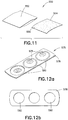
Fig. 11 is a perspective view of an exemplary set site placement preparation element in accordance with an exemplary embodiment of the present invention; -
Figs. 12a-12f are views of exemplary sets on tray packaging in accordance with an exemplary embodiment of the present invention; -
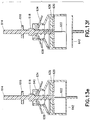
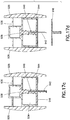
Figs. 13a-13f are views of an exemplary multistage insertion device in accordance with an exemplary embodiment of the present invention; -
Figs. 14a-14d are cross-sectional views of an exemplary "squeeze-type" inserter in accordance with an exemplary embodiment of the present invention; -
Figs. 15a-15e are views of an exemplary "contact-type" inserter in accordance with an exemplary embodiment of the present invention; -
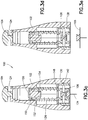
Figs. 16a-16c are views of an exemplary needle handle and shroud in accordance with an exemplary embodiment of the present invention; -
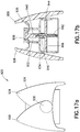
Figs. 17a-17d are views of an exemplary "skin pinch-type" inserter in accordance with an exemplary embodiment of the present invention; -
Figs. 18a-18e are views of an exemplary "folding/retracting-type" inserter in accordance with an exemplary embodiment of the present invention; -
Figs. 19a-19c are views of an exemplary "squeeze-type" latch provided as a connection method in accordance with an exemplary embodiment of the present invention; -
Figs. 20a-20d are views of an exemplary "tool-type" latch provided as a connection method in accordance with an exemplary embodiment of the present invention; -
Figs. 21a-21c are perspective views of an exemplary pull tie, tubing management element in accordance with an exemplary embodiment of the present invention; -
Figs. 22a-22c are perspective views of exemplary tubing connecting elements in accordance with an exemplary embodiment of the present invention; -
Figs. 23a-23b are perspective views of an exemplary elastic accordion, tubing management element in accordance with an exemplary embodiment of the present invention; -
Figs. 24a-24c are perspective views of an exemplary short tube, tubing management element in accordance with an exemplary embodiment of the present invention; -
Figs. 25a-25b are perspective views of exemplary pouch-type, tubing management elements in accordance with an exemplary embodiment of the present invention; -
Figs. 26a-26c are perspective views of exemplary decorative, functional covering elements in accordance with an exemplary embodiment of the present invention; -
Figs. 27a-27b are perspective views of an exemplary two-finger, placement element in accordance with an exemplary embodiment of the present invention; -
Fig. 28 is a perspective view of an exemplary insertion tool-mounted spray, site preparation element in accordance with an exemplary embodiment of the present invention; -
Fig. 29a-29c are views of an exemplary hub including an annular fluid reservoir and/or fluid path for use with one or more exemplary embodiments of the present invention; and -
Fig. 30 is a cross-sectional view of a catheter including one or more cross-drilled holes and a splined lumen in accordance with an exemplary embodiment of the present invention. - Throughout the drawings, like reference numerals will be understood to refer to like parts, components and structures.
- The embodiments of the present device described below illustrate a number of advanced, improved, and novel new components, elements and packaging of current and future infusion sets, that further provide simplicity in manufacture and use improvements for both insulin and non-insulin applications. Exemplary embodiments are presented in separate descriptions, although the individual features of these embodiments can be combined in any number of ways to meet the needs of the user.
- As will be appreciated by one skilled in the art, there are numerous ways of carrying out the examples, improvements and arrangements of insulin-associated devices disclosed herein. Although reference will be made to the embodiments depicted in the drawings and the following descriptions, the embodiments disclosed herein are not meant to be exhaustive of the various alternative designs and embodiments that are encompassed by the disclosed invention.
- The embodiments of the present device described below illustrate a number of features and elements in the areas of tube management, site management, set adhesion, set insertion, set placement and changing operations and packaging. A collection of exemplary embodiments of the present invention is shown by way of example in
Figs. 1 and2 , which serve to introduce elements described in greater detail below.Fig. 1 illustrates an exemplary infusion set 10 including the following features. As shown inFig. 1 , an exemplary infusion set can comprise an inserter, such as the squeeze-type inserter 700 for use with a set, such as the ring-sealedset 350. A tube and associated tube management devices, such as thecircular reel 450, can be provided for communication with an insulin pump (not shown) or with an insulin supply, such as theinsulin supply 475. A placement assistance element can be provided, such as theplacement assistance ring 526, and the entire arrangement can be placed into a sealedtray 12 with a number of site preparation elements, such as thepads 550, and site concealment elements, such as thepads 500. The tray can be comprised of any suitable plastic, fiber or composite material compatible with the components, and can provide compartments, padding or element securing detents or moldings. The set can be packaged in thetray 12 and sealed with a clear and/or labeledcover 14, and includes every component needed to position, connect, insert, and wear the set, as well as theinsulin 475 itself as shown inFig. 2 . Each of the exemplary components, including a number of additional or alternate components, will now be described individually in greater detail. - An exemplary embodiment of the present invention can be provided with an insertion device as desired by a user. An
exemplary insertion device 100 is shown inFigs. 3a-3e . The exemplary insertion device ofFigs. 3a-3e provides an insertion device which can contain the set at an open, patient-contacting end, and provide an actuation button at an opposite end. Upon activation, the insertion device places the set and automatically retracts the insertion needle back into the insertion device. - As shown in
Fig. 3a , the insertion device can comprise a substantiallycylindrical housing 102 from which a spring biased projection orpushbutton 104 can extend, and in which aset 106 can be positioned for use. Thehousing 102 can have a first diameter at a lower portion thereof in which theset 106 can be positioned, and transition to a reduced second diameter at an opposite end to substantially equal a diameter of thepushbutton 104. - Within the body of the
housing 102, a number of elements are contained which serve to fire theset 106 into position, and then retract the insertion needle. To do so, thehousing 102 comprises a first, second andthird chamber first chamber 108 at an uppermost portion of thehousing 102 has a width sufficient to slidably receive an end of aninserter rod 114. At an upper end of thefirst chamber 108, an opening is provided though which thepushbutton 104 slidably enters thefirst chamber 108, and a lower end of the first chamber opens to create thesecond chamber 110 as described in greater detail below. The first chamber further comprises at least oneinclined detent 116 disposed upon an inner wall of thefirst chamber 108 which serves to capture and secure a similar,deflectable detent 118 at an upper end of theinserter rod 114. One or more further similar,deflectable detents 120 are disposed upon anend 122 of thepushbutton 104 within thefirst chamber 108. Theend 122 of thepushbutton 104 is provided to have a width substantially equal to the width of thefirst chamber 108 to align and guide thepushbutton 104 during operation. Aspring 124 is disposed concentrically with thepushbutton 104 and is captured between an outer surface of thehousing 102 and an expanded head of thepushbutton 104 to constantly urge thepushbutton 104 upward. - As noted above, the
pushbutton 104 comprises anend 122 with one or moreinclined detents 120. When pressed downward, theinclined detents 120 come into contact with theinclined detents 118 of theinserter rod 114 which are being held by thedetents 116 of thefirst chamber 108. The contact releases thedetents 118 and allows theinserter rod 114 to be urged downward by afiring spring 126 disposed within thesecond chamber 110 of thehousing 102. - The
second chamber 110 has a width wider than that of thefirst chamber 108, which is sufficient to slidably receive theinserter rod 114 and more specifically, a width sufficient to slidably containplanar members inserter rod 114. Thefiring spring 126 is disposed concentrically with theinserter rod 114 about an outer circumference of the inserter rod body as captured within thesecond chamber 110. That is, thefiring spring 126 is captured within thesecond chamber 110 of thehousing 102 between an upper wall of thesecond chamber 110, and the upper surface of theplanar member 128 of theinserter rod 114. In doing so, thefiring spring 126 constantly urges theinserter rod 114 downward. - At a lower portion of the
housing 102, thethird chamber 112 can be provided having a width wider than that of thesecond chamber 110, thereby creating ashoulder 130 therebetween. As described in greater detail below, theshoulder 130 is configured to allow downward travel of theinserter rod 114 and capture one or more detents on an outer surface of theinserter rod 114 to prevent retraction of theinserter rod 114, yet permit full retraction of a needle carrier and inserter needle. - As noted above, the
inserter rod 114 is configured to slidably travel though each of the first, second andthird chambers housing 102. Theinserter rod 114 is substantially cylindrical and comprises a diameter at an upper portion substantially equal to the width of thefirst chamber 108 to be directed and guided by thefirst chamber 108 during use. A lower portion of theinserter rod 114 comprises the first and secondplanar members second chamber 110 to be directed and guided by the second chamber during use. - As noted above, the
inserter rod 114 comprises the first and secondplanar members inserter rod 114 further comprises aninserter needle guide 144 and at least third andfourth elements planar members spring 140 is captured between theneedle guide 144 andfourth element 138, and passes through an opening in thethird element 136, to constantly urge both the third andfourth elements third chambers fourth element 138 comprises aninclined detent 142 which is urged against the inner wall of the second andthird chambers inserter rod 114 is urged downward and thedetent 142 passes theshoulder 130, thespring 140 urges theelement 138 against the inner wall of thethird chamber 112 such that thedetent 142 is captured by theshoulder 130 and prevents the retraction of theinserter rod 114 as shown inFigs. 3c and 3d . The needle carrier and inserter needle are permitted to retract as described in greater detail below. - The
third element 136 comprises at least oneprojection 146 which is configured to capture agroove 154 in theneedle carrier 148 slidably disposed within an inner opening of theinserter rod 114. Theneedle carrier 148 secures theinserter needle 134 at a lower end, such that the inserter needle extends through theneedle guide 144 and though an opening in theplanar member 132 of theinserter rod 114. Theneedle carrier 148 further comprises thegroove 154 which can be captured by theprojection 146. The remainder of theneedle carrier 148 extends through theplanar member 128 and into the inner opening of theinserter rod 114 and terminates at aplanar end 150. Theplanar end 150 of theneedle carrier 148 has a width substantially the same as the width of the inner opening of theinserter rod 114 to align and guide theneedle carrier 148 during retraction. Aretraction spring 152 is captured between theplanar end 150 of theneedle carrier 148 and theplanar member 128 of theinserter rod 114. In doing so, theretraction spring 152 constantly urges theneedle carrier 148 upward. - While in the pre-use position, a large portion of the
second chamber 110 remains open to the end of the device. In doing so, theset 106 can be positioned on theextended needle 134, at an opposite side of the secondplanar member 132 of theinserter rod 114. Theset 106 can be gently held within thesecond chamber 110 through contact with the walls of the chamber, and/or through contact with theinserter needle 134. As noted elsewhere, theset 106 can include any number or configurations of adhesive pads (not shown) and other connection features, which can be accommodated by theinsertion device 100. - As shown in
Figs. 3a-3e , the compression of thepush button 104 releases theinclined detents 118 of theinserter rod 114 as shown inFig. 3a , permitting thefiring spring 126 to drive theneedle 134, set 106, and adhesive pad into the region of the skin beneath thethird chamber 112 of the device as shown inFig. 3b , and also releases thespring 140 to lock theinserter rod 114 in the extended position as shown inFig. 3c . That is, upon release, theinserter rod 114 is free to travel downward as urged by the trappedspring 126. In doing so, theinserter rod 114, including itsend 132 andneedle 134 travel downward through thethird chamber 112, urging theset 106 downward with it. At or before reaching the travel limit of theinserter rod 114, theset 106 is positioned, retraction of theneedle carrier 148 andneedle 134 occurs, and the device can be removed as shown inFig. 3d , thereby leaving theset 106 at the desired insertion site as shown inFig. 3e . - To retract the
needle carrier 148 andneedle 134, no user action is required. As shown inFigs. 3c-3d , theshoulder 130 serves to hold theinserter rod 114 in the down position. When the insertion is completed and theinserter rod 114 is captured in the down position by the outward movement ofmembers needle carrier 148 andneedle 134, and allows theneedle carrier 148 andneedle 134 to retract upward as urged by theretraction spring 152 as shown inFigs. 3c and 3d . Theneedle carrier 148 andneedle 134 are retracted until contacting anupper stop 156 disposed at an upper end of theinserter rod 114. - The
insertion device 100 ofFigs. 3a-3e uses the single button press of thepushbutton 104 to release the firing mechanism, insert theset 106, and safely retract theneedle 134 after insertion. Theinsertion device 100 is packaged and stored with the firing mechanism in an upright and locked position, with thefiring spring 126 compressed as shown. Theinserter rod 114 has the flexible wedge-shaped tabs or latches 120 at the top of it, which are locked into grooves or captured by thedetents 116 at the interior top of the inserter'sbody 102 as shown inFig. 3a . - Pressing the
activation button 104 unlatches the firing tabs at the top of the unit as shown inFig. 3b , and permits thefiring spring 126 to extend toward its free length, propelling theneedle carrier assembly 148 of theinserter rod 114 downward as shown inFig. 3c . Upon reaching the wider region of the body interior shaft at thethird chamber 112, the two spring-loaded locking halves ormembers needle carrier assembly 148 move outward and lock the firing mechanism in the down position as shown inFig. 3d , and frees the central portion of theneedle carrier assembly 148 to move upward as shown inFig. 3e , leaving the remainder of theinserter rod 114 in the down position. - By this time, the
needle 134 has pierced the skin and placed the cannula and set 106, adhering it to the skin. Having been decoupled from theinserter rod 114 which has been driven downward and locked, theneedle carrier assembly 148 is now free to rebound, propelled upward by theretraction spring 152 as shown inFig. 3e . After retracting fully upward, theneedle 134 is stored permanently and inaccessibly inside theinsertion device housing 102, and the device is inert. - In this and other inserter embodiments described below, the inserter body and elements can be constructed of any suitable and compatible materials such as plastic or metal. Springs can be provided as coil springs made of plastic or metal, although embodiments of the present invention are not limited thereto, and other spring or biasing means can be used, such as leaf spring or simply material resiliency. The insertion needle can comprise any suitable set insertion needle of metal or plastic, having length, thickness, and bevel dimensions suitable for set insertion.
- One or more of the exemplary embodiments of the present invention described herein can be further provided with additional features or elements to manage the degree of adhesion of the device in some manner as desired by a user. As shown by way of example,
adhesion management elements 300 are shown inFigs. 4a-4c . As shown inFigs. 4a-4c , aset 314 andcatheter 316 are shown encircled by concentric rings of adhesive 302 and 306. In an exemplary embodiment of the present invention, one ring can provide an adhesive with a higher degree of adhesion strength, and another ring can provide an adhesive with a lesser degree of adhesion strength, thereby allowing a user to tailor the degree of set adhesion to the user's activity plans. Although only two concentric rings of varied adhesive are shown inFigs. 4a-4c , in yet other embodiments of the present invention, more rings can be provided, or the rings may be provided in alternate, non-circular shapes (i.e., such as oval shapes). Further, in the exemplary embodiment shown inFigs. 4a-4c , theinner ring 306 is provided with the adhesive with a higher degree of adhesion strength and theouter ring 302 is provided with the adhesive with a lesser degree of adhesion strength, but embodiments of the present invention are not limited thereto. In yet other embodiments of the present invention, the order can be reversed or additional rings of adhesive provided. - As noted by those skilled in the art, a set typically requires a degree of adhesion to maintain proper positioning of the device. Accordingly, the exemplary embodiments of the present invention provide a set that comprises an adhesive pad or patch on the underside with a user-configurable adhesion mechanism to adapt the set to the expected environment in which it will be worn. As shown in
Fig. 4a , the adhesive pad or patch can be provided in two or more, selectable strengths which can be variably exposed and utilized depending on the user's preference. A region ofbasic adhesive 302 having aremovable cover 304 segmented from other covers, can be used for everyday needs while the region of extra-strong adhesive 306 remains covered by a similarsegmented cover 308 as shown inFig. 4b . The region of extra-strong adhesive 306 can be exposed by the removal of thecover 308 if athletic activities might be expected to stress the set adhesion as shown inFig. 4c . To further simplify use, eachcover tab covers - One or more of the exemplary embodiments of the present invention described herein can be further provided with additional features or elements to provide a simple but effective connection system as desired by a user. As shown by way of example, such a
connection method 350 is shown inFigs. 5a-5d . - In such an exemplary embodiment, a
set 352, once placed, has aport 354 that should be able to be easily connected and disconnected with atubing 358 leading to an insulin pump (not shown). To do, theset 352 can comprise the "self-sealing"connection port 354 on the outer, circular perimeter of theset 352, within acircumferential groove 356 on the body of theset 352 as shown inFig. 5a . Anincoming tube 358 can comprise a fitting 360 at the end designed to securely fit into and seal with theport 354 on theset 352, using the assistance of a flexible,resilient ring 362 extending outward from it as shown inFig. 5b . - Connection of the
tube 358 to theset 352 can then be accomplished by stretching thering 362 around the far side of theset 352 as guided by thegroove 356 to a first diameter to allow placement, then placing the connection fitting 360 into theport 354 as shown, and allowing theelastic ring 362 to contract to a second diameter to retain it securely as shown inFigs. 5c and5d . The tube, set and connectors can be constructed of any suitable material as described herein, and thering 362 can be constructed of any compatible, resilient material which can be easily molded into the desired shape and maintain elasticity at least for an expected shelf life of the device. In a similar manner, the exemplary embodiment of the present invention shown inFigs. 29a-29c , described in greater detail below, comprises an infusion set constructed of a soft, pliable and/or elastic or similar material such that the infusion set is soft or pliable to a degree that allows the elasticity of the materials to affix the tube ring of the tubeset connector to the hub in any number of rotational positions and which further includes a tubeset connector needle to pierce the hub, wherein the elasticity of the materials function to seal the insertion site of the tubeset connector needle. - One or more of the exemplary embodiments of the present invention described herein can be further provided with additional features or elements to allow site inspection in some manner as desired by a user. As shown by way of example, a
site inspection embodiment 400 is shown inFigs. 6a-6b . As shown inFigs. 6a-6b , aset 404 and its housing can include a means to inspect the region of the skin immediately surrounding the insertion point, to ensure that the site is in good condition. In an exemplary embodiment of the present invention, theset 404 can include anelement 402 extending from a top surface to a bottom surface of theset 404 at some point near the insertion site. As shown inFigs. 6a-6b , theelement 402 completely encircles the site, but embodiments of the present invention are not limited thereto. In yet other embodiments of the present invention, theelement 402 can be provided over a narrower portion, but still sufficient to view the site from above the device. - The
element 402 can be constructed of any suitable material that can be easily manufactured, bonded with the remaining elements of theset 404, provide compatibility with the contents or other materials, including the skin surface, and provide a degree of visibility between the top and bottom surfaces of theset 404. As shown inFig. 6b , the sides of theelement 402 can be configured, contoured or otherwise provided with features to be held in place by the body of theset 404, and a top surface can be contoured to add a degree of magnification. For example, the housing of theset 404 or the top surface of theelement 402 can include or comprise a clear plastic magnifying element that allows for even better site inspection abilities. - Further, the
element 402 can be provided with an upper surface opening 412 to secure aseptum 414 and for insertion of aplacement needle 408 into acatheter 410. Theelement 402 can further provide anopening 416 to facilitate introduction of the infusion substance through thetubing 406. Still further, where the lower surface of theset 404 is provided with an adhesive pad (not shown) at the base of theset 404, the adhesive pad can include a cutaway portion to permit visibility through theelement 402. - One or more of the exemplary embodiments of the present invention described herein can be further provided with additional features or elements to secure, contain, and/or conceal the tubing of the device in some manner as desired by a user. As shown by way of example, a
tube management reel 450 is shown inFigs. 7a-7b . Thetubing 452 connecting the insulin supply and pump (not shown) to the infusion set (not shown) can be packaged on a spring-loadedcircular reel 454 disposed within or at one side of areel housing 456. - As shown in the cross-sectional view of
Fig. 7b , thetubing 452 can enter and exit thehousing 456 at opposite sides near an upper surface, and wrap about a spring mechanism using pins 458. The construction of a spring-loaded circular reel is known to those skilled in the art, so additional features of which are omitted for clarity. However, the circular reel is provided withpins 458 between which thetube 452 is secured within thehousing 456 such that, feeding tubing from the housing results in the circular reel being wound tighter, and feeding tubing into the housing results in the circular reel being unwound and relaxed. Accordingly, the circular reel and pins maintain a tension on thetube 452 urging the tubing into the housing. - The circular reel can further comprise a catch/latch mechanism as known to those skilled in the art such that pulling the tube 452 a first time feeds a length of tube and a catch is provided to prevent a reverse spring-urged action. Upon pulling the tube 452 a second time, the catch can be released so that the reverse spring-urged action is released to urge the
tube 452 back into thehousing 456. In doing so, the reel device allows slack tubing to be fed out precisely, with spring resistance maintaining the excess tubing rolled up and stored. The locking switch or latch can be provided to allow the user to prevent inadvertent retraction or extension once a satisfactory length of tubing has been deployed. The device can further comprise aswitch 460 to actuate the tube retrieval. - One or more of the exemplary embodiments of the present invention described herein can be further provided with additional features or elements to provide an insulin supply in some manner as desired by a user. As shown by way of example, an
insulin supply 475 is shown inFig. 8. Fig. 8 illustrates an exemplary embodiment of aninsulin container 476 and associatedtubing 478, including a tubing connection means 480. Theinsulin supply 476 can be packaged in a small, sealed or sealable container that is pre-connected to a length oftubing 478. Theinsulin container 476 can be integrated with a pump mechanism (not shown) externally via an installation process which the user can easily perform. Theinsulin container 476 andtubing 478, once connected to a set and pump, form a system that does not need to be primed for proper function. - The
insulin container 476 can be constructed of any suitable material, such as glass or plastic, to be clear to show the contents, or non-clear or opaque to protect contents from light. Thecontainer 476 can further include incremental dosage measurement marks along one or more surfaces for use during content delivery. The associatedtubing 478 and connection means 480 can be constructed of any suitable material, such as rubber, to provide flexibility and compatibility with the contents. The connection means 480 can be constructed in any number of ways, for example, including the connection means described in greater detail below in regard toFigs. 22a-22c . - One or more of the exemplary embodiments of the present invention described herein can be further provided with additional features or elements to provide set concealment in some manner as desired by a user. As shown by way of example, a
concealment element 500 is shown inFigs. 9a-9b . InFig. 9a , anadhesive covering 502, similar to a large adhesive bandage, can be provided to enable the user to cover the site, including theset 504, with an inconspicuous dressing. In an exemplary embodiment of the present invention, the covering 502 comprises a flexible, skin-colored adhesive covering that can have an adhesive side and a non-adhesive side. The adhesive side can be covered with a user-removable cover (not shown) that when removed, allows the covering 502 to be secured over the site, thereby covering and to a large degree, concealing theset 504 as shown inFig. 9b . - One or more of the exemplary embodiments of the present invention described herein can be further provided with additional features or elements to aid and/or simplify placement of the device in some manner as desired by a user. As shown by way of example, a collection of
placement assistance elements 525 is shown inFigs. 10a-10c . Since the set and the corresponding insertion device can be unavoidably large in diameter and difficult to accurately locate in some circumstances, an exemplary kit including embodiments of the present invention can further include a placement ring to aid in placement of the set. Anexemplary placement ring 526 is shown inFig. 10a and can comprise a ring-shaped plastic part with one or more orienting features 530, such as keys, on its perimeter, and a self-adhesive, covered pad on the underside (not shown). A low-profile, contoured circular plastic ring is shown, but embodiments of the present invention are not limited thereto. As thering 526 can be provided with an adhesive pad, thering 526 can be first gently adhered to the skin surface with the target insertion site at the center as shown inFig. 10b . This allows careful set placement as the insertion site can now be better visualized though a center opening of thering 526, and theinsertion device 528, or tool, can be aligned with, and guided into final position, by theplacement ring 526. - The
insertion device 528 can be provided for use with theplacement ring 526, and be constructed as described elsewhere herein and further having corresponding detents orkeyways 532 to align with and receive the orienting features 530 of theplacement ring 526. When theinsertion device 528 is to be placed atop theplacement ring 526 as shown inFig. 10c , theinsertion device 528 self-aligns and orients for precise location of aset 534. In the exemplary embodiment shown, the orienting features 530 are formed as raised contoured detents. Therefore, each further serves to guide, center and align theinsertion device 528 upon placement. That is, such contoured elements provide a degree of self-alignment not as readily provided by square elements for example. After insertion, theset 534 is left remaining at a center of thering 526 upon removal of theinsertion device 528. Theplacement ring 526 can then be removed and discarded. - One or more of the exemplary embodiments of the present invention described herein can be further provided with additional elements for the use of site preparation. Such an exemplary feature is shown in
element 550 ofFig. 11 . In the exemplary embodiment shown inFig. 11 , set packaging can further include a site preparation wipe 554 contained within apreservation container 552. The packaging for the set can include the wipe 554, such as a versatile disposable wipe, paper or cloth pad that is soaked or impregnated with one or more of a disinfectant, local anesthetic or other helpful substance. The pad or wipe 554 may also be constructed having a texture, coating, or other surface feature 556 that can provide an exfoliating ability to aid in anesthetic effectiveness. - One or more of the exemplary embodiments of the present invention described herein can be further provided with additional features or elements to provide a simple but effective means to provide packaging as a number of sets upon a tray as desired by a user. As shown by way of example, a "sets on tray"
packaging arrangement 575 is shown inFigs. 12a-12f . As shown inFigs. 12a-12f , a number ofexemplary sets 576 can be packaged upon atray 578. Although the exemplary tray ofFig. 12a shows the containment of three sets, any number or arrangements of sets can be included as desired by the user. - As shown in
Fig. 12a , a number of disposable sets or setcomponents 576 can be packaged in the exemplary multi-unit, foil or plastic-sealedtray 578. In the exemplary embodiment of the present invention shown inFig. 12a , thetray 578 can be constructed of any suitable material compatible with the set and set components to be stored therein, and can provide a number of recessed, contoured or otherwise constructedopenings 580 into which the sets or setelements 576 can be positioned. Theopenings 580 can be configured to securely hold and protect the sets prior to use, allow easy covering of the sets and tray surface with a sealing means, such as foil or other material which can then be easily removed or punctured by the user to access the desired set and maintain protection of remaining sets as shown inFig. 12a , and which allows such access and removal using aninserter device 582 as shown inFigs. 12c-12f . - As illustrated in the cross-sectional views of
Figs. 12c-12f , anexemplary insertion device 582 is shown having a contoured shape into which theset 576 can be captured. To do so, theinsertion device 582 can comprise one or mover deflectable ends 584 which can have aninclined latch 590 to pierce the tray covering 588 as shown inFig. 12d , deflect outward slightly due to contact with theset 576, and then capture an outer circumference of theset 576 once thelatch 590 is fully inserted. In doing so, theinsertion device 582 can be used to extract anew set 576 from the package so that the user will not need to contend with opening and unsealing packaging materials. For example, an exemplary andreusable insertion device 582 for use which such a tray can comprise a hollow underside or lower surface, with the engagement features of thelatches 590 oriented inward towards theset 576, such that a user is simply required to align theinsertion device 582 with a set, insert to a sufficient depth and retrieve theset 576 for use. No further user action is required in regard to handling theset 576. - As shown in
Fig. 12c , thesets 576 are aligned within each opening of the tray with sufficient clearance below the set to accommodate any elements of the set. A substantial portion of the upper surface of the set can be exposed, wherein a foil orother covering 588 can be used to secure theset 576 within the tray, and seal the contents of the tray and set 576 from contamination or other damage. In this exemplary embodiment of the present invention, thefoil 588 is shown covering the limited space surrounding each device, but is not limited thereto. In yet other embodiments of the present invention the foil or covering can be more or less extensive upon the tray surface as desired. - As shown in
Fig. 12d , theinsertion device 582 can self-align on the blister-type package of theset 576 on thetray 578, and when pressed down, can cut through the foil orplastic seal 588 as shown inFigs. 12c and 12d . As theinsertion device 582 presses down further, it also disengages the set 576 from thepackaging tray 578 with the perimeter of the inserter body. After pushing past the edge of theset 576, the locking tabs or latches 590 on theinsertion device 582 engage and secure the outer circumference of theset 576, and allow the user to extract both theinsertion device 582 and the set 576 from thetray 578 as shown inFig. 12f . The insertion device and the set are then ready to fire in normal use. The remaining sets of the tray are left intact and ready for later use. In exemplary embodiments of the present invention, the removal of the set 576 from the tray also results in the automatic removal of any needle cover and adhesive backing, which is left with thetray 578. - One or more of the exemplary embodiments of the present invention described herein can be further provided with additional features or elements to provide a simple but effective multistage-type inserter as desired by a user. As shown by way of example, a "multistage-type"
inserter device 600 is shown inFigs. 13a-13f . In such an exemplary embodiment, the insertion device can be constructed in such a way as to separate high-cost parts from low-cost parts, keeping the former in a reusable mechanism while allowing the latter to be safely disposed. - As shown in
Fig. 13a , the multistage-type inserter device 600 can comprise a substantially cylindrical upper andlower element upper element 602 can have a first diameter at a lower portion thereof to seamlessly mate with thelower element 604. An upper portion of theupper element 602 can have a second diameter which is flared or expanded to provide sufficient room for operation of hingedlatches 606 as described in greater detail below. Thelower element 604 can also have a first diameter at an upper portion thereof to seamlessly mate with theupper element 602, and a second diameter at a lower portion which is flared or expanded to contain aset 642. - The
upper element 602 can comprise at least one firing mechanism consisting of at lease one hingedlatch 606 rotatable about apin 608 or other means, and which has ainclined projection 610. Eachprojection 610 includes an inclined lower surface to facilitate assembly with thelower element 604, and a substantially flat upper surface to restrict some portion of aninserter rod 614 as described in greater detail below. Theupper element 602 further comprises afirst chamber 612 in which afiring spring 624 is captured. Theupper element 602 and contents thereof can comprise a reusable element that can be installed onto a disposable mechanism of thelower element 604 which can include a set, needle, adhesive pad, and a portion of the insertion mechanism. - The
inserter rod 614 extends though both the upper andlower elements shoulder 618 and aplanar end 620. Theinserter rod 614 further comprises aninserter needle 622, which can be secured within a center opening of theinserter rod 614, and can extend downward from the rod at theend 620. Both the cross-member 616 and thelower end 620 are configured to have a width substantially equal to the width of the chamber in which each is positioned to facilitate alignment and travel of theinserter rod 614 during use. As described in greater detail below, the cross-member 616 is configured to be held in an up position by theprojections 610 of thelatches 606, and is configured to be blocked at a down position by theprojections 633 of thelower element 604. Further, the lower part of theshoulder 618 is configured to have a partially flat surface upon which theretraction spring 638 rests, and a partially inclined surface such that the shoulder can be easily forced through the opening of thepartition 634 by thefiring spring 624. The upper part of theshoulder 618 is configured to have a substantially flat surface to be captured by the opening of thepartition 634 and prevent upward travel of theinserter rod 614 for retraction until released. - The
upper portion 602 comprises thefirst chamber 612 in which thefiring spring 624 is captured. Thefiring spring 624 is disposed concentrically about theinserter rod 614 and is captured between an upper wall of thefirst chamber 612 and thecross-member 616 of theinserter rod 614. In doing so, thefiring spring 624 is configured to constantly urge theinserter rod 614 downward. Prior to use, theinserter rod 614 is held in an up position by one or more of theprojections 610 of the hingedlatch 606. Specifically, an inner surface of the hingedlatch 606 comprises one or more of theprojections 610 which extend a slight distance from the inner surface of the hingedlatch 606, and which block the travel of thecross-member 616 of theinserter rod 614. In such a position, thefiring spring 624 is compressed and thelatches 606 capture the upper portion of the needle assembly as shown inFig. 13b . The capture of the upper portion of theinserter rod 614 by theprojections 610 of thelatches 606, and the force applied by thefiring spring 624 while in the pre-use position, also serves to secure theupper housing 602 to thebottom housing 604 prior to use. Once thelatches 606 are released from theinserter rod 614, theupper housing 602 is free of thelower housing 604 and can be lifted away as shown inFigs. 13c-13d . - The
upper housing 602 can further comprise anopening 642 which can serve to support thefiring spring 624 in position, and serve to guide theinserter rod 614 during use. Theopening 642 can further reveal an extended portion of theinserter rod 614 as shown inFig. 13b such that a user can confirm visually or by touch that the elements are all present and are properly assembled and ready for use. - The
lower portion 604 comprises a second, third andfourth chamber second chamber 626 is substantially open at an upper surface to slidably receive theinserter rod 614 as guided by the cross-member 616 as urged downward by thefiring spring 624 when released. Thesecond chamber 626 comprises at least oneprojection 633 which extends inward from an inner surface of thesecond chamber 626. In doing so, theprojection 633 provides a downward travel limit of theinserter rod 614 through the contact between the cross-member 616 and theprojection 633. As noted above, the width of the second chamber and the cross-member 616 are configured such that theinserter rod 614 is centered and guided by each. - The second and
third chambers partition 634 having anopening 640 through which theinserter rod 614 extends. Theopening 640 of thepartition 634 is configured to have an inclined upper opening surface through which the inclined lower surface of theshoulder 618 can more easily pass as urged downward by thefiring spring 624. The lower surface of theopening 640 of thepartition 634 is configured to be substantially flat such that the flat upper surface of theshoulder 618 cannot pass back though thepartition 634 until released for retraction as described in greater detail below. Further, thepartition 634 comprises at least one segment extending some distance from an outer surface of the lower element 604 (i.e., an extended user lever) such that thepartition 634 can be deflected by the user for retraction as described in greater detail below. - The third and fourth chambers are also separated by a
partition 636, which also includes an opening through which theinserter rod 614 extends. Thethird chamber 628 further comprises theretraction spring 638. The retraction spring is positioned concentric with theinserter rod 614, and is captured within thethird chamber 628 between thepartition 636 and theshoulder 618 of theinserter rod 614. In doing so, theretraction spring 638 is configured to constantly urge theinserter rod 614 upward. - Prior to use, the
firing spring 624 in theupper portion 602 is compressed and theretraction spring 638 in thelower portion 604 is relaxed as shown inFig. 13b . During use, the release of thefiring spring 624 operates the inserter as described in greater detail below, and further serves to compress theretraction spring 638 as shown inFig. 13c . After use, theinserter rod 614 is held in position by the contact between theshoulder 618 and thepartition 634 as shown inFig. 13d . To retract theinserter rod 614, the user than presses on the extended portions of thepartition 634. As shown inFigs. 13d and13e , therestrictive opening 640 of thepartition 634 serves to hold theinserter rod 614 in the down position. When the insertion is completed and theupper portion 602 is removed, the user can press the extended portions of thepartition 634, and theopening 640 is enlarged and allows theshoulder 618 to retract upward as urged by theretraction spring 638 as shown inFig. 13e . - While in the pre-use position, a large portion of the
lower portion 604 remains open to the end of the device. In doing so, theset 642 can be positioned on theextended needle 622, at an opposite side of theend 620 of theinserter rod 614. Theset 642 can be gently held within theportion 604 through contact with the walls of the portion, and/or through contact with theinserter needle 622. As noted elsewhere, the set can include any number or configurations of adhesive pads (not shown) and other connection features, which can be accommodated by the two-part inserter. - As shown in
Figs. 13a-13f , the compression of thelatches 606 releases the projection latch on the needle assembly of theinserter rod 614, permitting thefiring spring 624 to drive theneedle 622, set 642, and adhesive pad into the region of the skin beneath theportion 604, and also compress theretraction spring 638. That is, upon release, theinserter rod 614 is free to travel downward as urged by the trappedspring 624. In doing so, theinserter rod 614, including itsend 620 andneedle 622 travel downward through theportion 604, urging theset 642 downward with it. At or before reaching the travel limit of theinserter rod 614, the set is positioned, and the device can be removed as shown inFig. 13f , thereby leaving theset 642 at the desired insertion site. - Then, to retract the
inserter rod 614, including itsend 620 andneedle 622, the user then presses on the extended portions of thepartition 634. As shown inFigs. 13d and13e , therestrictive opening 640 of thepartition 634 serves to hold theinserter rod 614 in the down position. When the insertion is completed and theupper portion 602 is removed, the user can press the extended portions of thepartition 634, and theopening 640 is enlarged and allows theshoulder 618 to retract upward as urged by theretraction spring 638 as shown inFig. 13e . Theinserter rod 614 is prevented from completely exiting thelower portion 604 by the contact between thelower end 620 and thepartition 636. - As noted above, the exemplary embodiment of the present invention illustrates an
insertion device 600 that can be constructed in such a way as to separate high-cost parts from low-cost parts, keeping the former in a reusable mechanism while allowing the latter to be safely disposed as shown inFig. 13a . A firing mechanism consisting of the hinged latches 606 and an extended, large spring is installed onto a disposable mechanism which includes theset 642, theneedle 622, the adhesive pad, and a portion of the insertion mechanism. As shown, thefiring spring 624 is compressed and thelatches 606 capture the upper portion of the needle assembly orinserter rod 614 as shown inFig. 13b . The device is now ready to be placed and fired. - Once the user squeezes the
latches 606 on the upper part of the device, the needle assembly orinserter rod 614 becomes free to move, and is driven downward by thefiring spring 624, piercing the skin, inserting and adhering theset 642 as shown inFig. 13c . The downward motion of the needle assembly orinserter rod 614 also drives two secondary latches on the lower portion of the device outward to capture theinserter rod 614 within theopening 640 and compresses the return orretraction spring 638. After removal of thereusable part 602 of thedevice 600, the lower part of thedevice 604 remains in place and the needle will still be inserted in the skin as shown inFig. 13d . To remove theneedle 622, the latches or themember 634 can be deflected as shown inFig. 13e to allow the return orretraction spring 638 to extract theneedle 622 and render thelower part 604 of theassembly 600 inert and disposable. Theinserter rod 614 is prevented from completely exiting thelower portion 604 by the contact between thelower end 620 and thepartition 636. - One or more of the exemplary embodiments of the present invention described herein can be further provided with additional features or elements to provide a simple but effective "squeeze-type" inserter as desired by a user. As shown by way of example, a "squeeze-type"
inserter device 700 is shown inFigs. 14a-14d . As shown inFigs. 14a-14d , an exemplary embodiment of the present invention can be activated by pressing the device against the targeted portion of the skin and then squeezing a portion of the inserter body. - An exemplary construction of the squeeze-
type insertion device 700 can comprise a body having at least threeportions portions deflectable portion 704 disposed therebetween. Theupper portion 702 can comprise a substantially cylindrical outer surface having a rounded and closed end, and an opposite end which seamlessly mates with the outer surface of the user-deflectable portion 704. Thelower portion 706 can have a larger diameter, substantially cylindrical outer surface, with a contour configured to seamlessly mate with the outer surface of the user-deflectable portion 704. Accordingly, the user-deflectable portion 704 can have a substantially cylindrical outer surface having a contour to provide seamless mating with the outer surface of the upper andlower portions portions deflectable portion 704 as described in greater detail below. Further, aninserter rod 712 is slidably captured within thedevice 700 and extends through each portion as guided by aninserter rod cross-member 714. Theinserter rod 712 further comprises a lowerplanar end 722 and aninserter needle 724, which can be secured within a center opening of theinserter rod 708, and can extend downward from theinserter rod 712 at theend 722. Both the cross-member 714 and thelower end 722 are configured to have a width substantially equal to the width of the chamber in which each is positioned to facilitate alignment and travel of theinserter rod 712 during use. - As shown in
Figs. 14a-14c , theupper portion 702 provides afirst chamber 708 in which afiring spring 710 is captured. Specifically, thefiring spring 710 is positioned concentric with theinserter rod 712, and is captured at one end by an upper wall of thefirst chamber 708, and at an opposite end by theinserter rod cross-member 714. In doing so, thefiring spring 710 is configured to constantly urge theinserter rod 712 downward. - Prior to use, the
inserter rod 712 is held in position by one ormore projections 716. Specifically, an inner circumference of the user-deflectable portion 704 comprises one or more of theprojections 716 which extend a slight distance from the inner circumference of the user-deflectable portion 704, and which block the downward travel of thecross-member 714 of theinserter rod 712. Theprojections 716 are provided at an uppermost point of theportion 704 as this point undergoes the greatest degree of deflection during user deflection as described in greater detail below. Accordingly, in such a position, the degree of deflection of theprojections 716 is maximized as shown inFig. 14b to simplify the release of theinserter rod 712. - The user-
deflectable portion 704 provides asecond chamber 718 through which theinserter rod 712 is positioned and which includes atravel limit element 720. Although any part of the user-deflectable portion 704 can be compressed by a user, an exemplary embodiment of the present invention can provide one or more designations on an outer surface of the user-deflectable portion 704 to identify each as a preferred "squeeze button" area. Once the user-deflectable portion 704 is compressed by the user as shown inFig. 14b , theprojections 716 release thecross-member 714 of theinserter rod 712 and thefiring spring 710 urges theinserter rod 712 downward through thesecond chamber 718 until the cross-member 714 is restricted from further downward travel by thetravel limit element 720 as shown inFig. 14c . As noted above, theportions deflectable portion 704. Accordingly, the engagement between theportions portions inserter rod 712. - While in the pre-use position, a large portion of the
lower portion 706 remains open to the end of the device. In doing so, aset 726 can be positioned on theextended needle 724, at an opposite side of theend 722 of theinserter rod 712. Theset 726 can be gently held within theportion 706 through contact with the walls of the portion, and/or through contact with theinserter needle 724. As noted elsewhere, theset 726 can include any number or configurations of adhesive pads (not shown) and other connection features, which can be accommodated by the squeeze-type inserter. - As shown in
Figs. 14a-14d , the compression of the user-deflectable portion 704 releases theprojection latch 716 on the needle assembly of theinserter rod 712, permitting thefiring spring 710 to drive theneedle 724, set 726, and adhesive pad into the region of the skin beneath theportion 706. That is, upon release, theinserter rod 712 is free to travel downward as urged by the trappedspring 710. In doing so, theinserter rod 712, including itsend 722 andneedle 724 travel downward through theportion 706, urging theset 726 downward with it. At or before reaching the travel limit of theinserter rod 712, theset 726 is positioned, and thedevice 700 can be removed as shown inFig. 14d , thereby leaving theset 726 at the desired insertion site. - Such an exemplary embodiment of the present invention provides a more convenient means of actuating an insertion device by simply using "squeeze" buttons to initiate the process as shown in
Fig. 14a . As shown inFig. 14b , buttons on the side of the device at the user-deflectable portion 704 can be pressed inward, unlatching the needle assembly orinserter rod 712 and permitting it to be propelled downward by thefiring spring 710 as shown inFigs. 14b and14c . The spring-loaded needle delivers theset 726 and adhesive pad to the skin. Thedevice 700 can then be removed as shown inFig. 14d , thereby leaving theset 726 at the desired insertion site. - In contrast to the other inserter devices described herein, the materials of the squeeze-
type inserter 700 allow for the squeeze action of the one or more portions, or the construction of one or more portions having thinner, thereby deflectable parts. - One or more of the exemplary embodiments of the present invention described herein can be further provided with additional features or elements to provide a simple but effective skin contact-type inserter as desired by a user. As shown by way of example, a "skin contact-type"
inserter device 800 is shown inFigs. 15a-15e . As shown inFigs. 15a-15e , an exemplary embodiment of the present invention is shown wherein the insertion device can be activated by pressing the device up against the targeted portion of the skin. - An exemplary construction of the
insertion device 800 can comprise an upper andlower portion upper portion 802 can be comprised of a dome-shaped element into which a slidably engagedlower portion 804 can be captured. Specifically, theupper portion 802 can comprise a substantially round, dome-shaped element having a flattened portion at an uppermost point. Theupper portion 802 can further comprise one or moredeflectable tabs 806, or cut portions, about a body circumference as described in greater detail below. The inner surface of thetabs 806 are provided with anincline 824 and aprojection 818 at the uppermost point of each incline. - Within the
upper portion 802, exemplary embodiments of the present invention comprise aninserter rod 808 slidably disposed within the upper portion and which is held in place by thetabs 806. As shown inFigs. 15b-15e , theinserter rod 808 comprises aplanar end 814 wherein anotch 816 is proved at each side of theplanar end 814, which engages theprojections 818 of thetabs 806 that extend into theupper portion 802. Accordingly, prior to use, theprojections 818 secure thenotches 816 of theplanar end 814 of theinserter rod 808, preventing movement of theinserter rod 808. Theinserter rod 808 further comprises aninserter needle 828, which can be secured within a center opening of theinserter rod 808, and can extend downward from the rod at theplanar end 814. - The
upper portion 802 further comprises afiring spring 810 that is disposed concentrically with theinserter rod 808 and which is captured between theend 814 of theinserter rod 808 and one or more features of the upper flattened surface of theupper portion 802. In the exemplary embodiment shown, the upper flattened surface of theupper portion 802 can comprise amolding 820 having a cup-shapedopening 812 that is sized to capture and hold an end of thefiring spring 810. In this position, thefiring spring 810 serves to constantly urge theinserter rod 808 downward. However, as noted above, prior to use, theinserter rod 808 is held in place by thetabs 806. - Accordingly, the
device 800 further comprises the slidably engagedlower portion 804 which is slidably captured at an end of theupper portion 802 by one or more contactingtabs 822 ofportion 804, andtabs 832 of theupper portion 802. Thelower portion 804 has a diameter slightly less than an inner diameter of theupper portion 802 such that thelower portion 804 is gently held in place prior to use but upon contact with a skin surface, can be easily slid upward into theupper portion 802. In doing so, thetabs 822 of thelower portion 804 travel against an inner circumference of theupper portion 802, and onto thetabs 806. Specifically, thetabs 822 of thelower portion 804 travel against theincline 824 of thetabs 806, which forces thetabs 806 outward and releases theprojections 818 from thenotches 816 of theplanar end 814 of theinserter rod 808 as shown inFig. 15c . Once released in such a manner, theinserter rod 808 is free to travel downward as urged by thefiring spring 810. - While in the pre-use position, a large portion of both the upper and
lower portions device 800. In doing so, aset 826 can be positioned on theextended needle 828, at an opposite side of theplanar end 814 of theinserter rod 808. Theset 826 can be gently held within theupper portion 802 through contact with the walls of the upper or lower portion, and/or through contact with theinserter needle 828. As noted elsewhere, theset 826 can include any number or configurations of adhesive pads (not shown) and other connection features, which can be accommodated by the skin contact inserter. - As shown in
Figs. 15b-15d , the slidable motion of thelower portion 804 into theupper portion 802 releases thepin latch 818 on the needle assembly of theinserter rod 808, permitting thefiring spring 810 to drive theneedle 828, set 826, and adhesive pad into the region of the skin beneath thelower portion 804. That is, upon release, theinserter rod 808 is free to travel downward as urged by the trappedfiring spring 810. In doing so, theinserter rod 810, including itsend 814 andneedle 828 travel downward through thelower portion 804, urging theset 826 downward with it. At or before reaching the travel limit of theinserter rod 808, theset 826 is positioned, and thedevice 800 can be removed as shown inFig. 15e , thereby leaving theset 826 at the desired insertion site. - As described above, the
lower portion 804 of the device becomes a movable actuation mechanism. In this case, a circumference or ring around the lower perimeter of thelower portion 804 of the device, surrounding theset 826 andneedle 828, is placed against the skin surface (not shown). The entirety of thedevice 800 is then pressed firmly downward. The lower ring of thelower portion 804 telescopes into the main body of theupper portion 802 of the device and as it travels inward/upward, it deflects the multiple latches around the perimeter provided by thetabs 806, which permit thefiring spring 810 to drive theneedle 828, set 826, and adhesive pad into the skin. Thedevice 800 can be removed as shown inFig. 15e , thereby leaving theset 826 at the desired insertion site. - One or more of the exemplary embodiments of the present invention described herein can be further provided with additional features or elements to provide a needle handle and/or shroud in some manner as desired by a user. As shown by way of example, a needle handle and
shroud 900 is shown inFigs. 16a-16c . In doing so, an enhancement can be provided to current manually inserted needles for set insertion by implementing aplastic handle 902 and a substantially circular and hingedshield 904 for use with theneedle 906 and set (not shown). Thehandle 902 permits a sure grip on theneedle 906 for insertion, while thecircular shield 904, as shown, helps to firmly press the set and set adhesive into place as shown inFig. 16a . After placement, when theneedle 906 is withdrawn, the hinged portions of theshield 904 can be folded down at each of hinges 908, as shown inFigs. 16b and the cross-sectional view ofFig. 16c , to allow for safer needle disposal. - One or more of the exemplary embodiments of the present invention described herein can be further provided with additional features or elements to provide a simple but effective skin pinch-type inserter as desired by a user. As shown by way of example, a "skin pinch-type"
inserter device 925 is shown inFigs. 17a-17d . As shown inFigs. 17a-17d , an exemplary set can be packaged with a skin pinch-type inserter 925 with which a user can grasp a portion of the user's skin to improve insertion of the set. Theexemplary insertion device 925 can be integrated into a mechanism as described in greater detail below that incorporates features to do this. - An exemplary construction of the
insertion device 925 can comprise a large clothespin-like clamp 926, having opposite sides orlegs 928 which rotate about a pin or other securing means 930. Such anexemplary clamp 926 can further provide a space therein in which a number of remaining components can be centered. The large clothespin-like clamp 926 can include the wide, manually-actuatedlegs 928 as shown inFigs. 17a-17b . Thelegs 928 can be configured to be at slight angles while at rest such that a width between thelegs 928 at the skin contact surface is wider than a width between thelegs 928 at opposite ends. When activated by a user, the user places theentire device 925 against the skin surface such that the wider opening contacts the skin surface. The user than grasps thelegs 928 at a point near the skin surface and "pinches" thelegs 928 into a substantially parallel position, such that thelegs 928 extend vertically from the skin surface as shown inFig. 17c . That is, the device can be placed on the skin surface, surrounding the target area, and the pinchinglegs 928 can be squeezed inwards. When pinched, thelegs 928 in contact with the skin surface serve to prepare the skin surface in a number of different ways for set placement, including, but not limited to, stretching the skin at the site, leveling the skin at the site and/or raising the skin at the site. - The squeezing of the
legs 928 is also tied to a latching mechanism in the central section of thedevice 925. That is, when a desired degree of skin pinch is achieved, the device automatically begins the process of releasing and placing the set. To do so, thedevice 925 can further comprise a first and second chamber therein. Thefirst chamber 932 is secured to thesecond chamber 934, which is secured at opposite corners to an inner surface of thelegs 928. Thelegs 928 further comprise at least one articulatedpin 936 which is inserted into thefirst chamber 932 when the device is at rest as shown inFig. 17b . The articulatedpin 936 can include one or more joints or segments along its length, such that there is no interference with the movement of thelegs 928 during operation. - The articulated
pin 936 extends from an inner surface of thelegs 928, through an opening in the side of thefirst chamber 932 and secures aplanar end 938 of aninserter rod 940. As shown inFig. 17b , in doing so, thepin 936 holds theinserter rod 940 in an up and retracted position. As thelegs 928 are pinched, the articulatedpin 936 is pulled clear of theplanar end 938 which allows theinserter rod 940 to move forward as urged by afiring spring 946. - As shown in
Figs. 17b-17c , thefiring spring 946 is captured in thesecond chamber 934. Specifically, the first and second chambers are in communication via an opening therebetween through which theinserter rod 940 extends. Theplanar end 938 of theinserter rod 940 is captured in the first chamber, and can be held at an upper and retracted position in the first chamber by the articulatedpin 936. The remainder of the inserter rod extends into thesecond chamber 934 and terminates at an oppositeplanar end 944, and further comprises aninserter needle 942. Theinserter needle 942 can be secured within a center opening of theinserter rod 940, and can extend from the rod at theplanar end 944 into thesecond chamber 934. Both planar ends 938 and 944 are configured to have a width substantially equal to the width of the chamber in which each is positioned to facilitate alignment and travel of theinserter rod 940 during use. - The
firing spring 946 is placed concentrically about theinserter rod 940 and is captured by theinserter rod 940 within thesecond chamber 934, between theend 944 and an upper wall of thesecond chamber 934, and is configured to be in a compressed state prior to use, and upon release of the articulatedpin 936, is further configured to urge theinserter rod 940 downward toward the insertion site. As shown inFig. 17b , while in the pre-use position, a large portion of thesecond chamber 934 at an opposite side of theplanar end 944 remains open to the end of the device. In doing so, aset 948 can be positioned on theextended needle 942 within thesecond chamber 934, at an opposite side of theplanar end 944 of theinserter rod 940. Theset 948 can be gently held within thesecond chamber 934 through contact with the walls of the chamber, and/or through contact with theinserter needle 942. As noted elsewhere, theset 948 can include any number or configurations of adhesive pads (not shown) and other connection features, which can be accommodated by the skin pinch inserter. - As shown in
Figs. 17b-17c , the motion of thelegs 928 releases thepin 936 latch on the needle assembly of theinserter rod 940, permitting thefiring spring 946 to drive theneedle 942, set 948, and adhesive pad into the pinched region of the skin. That is, upon release of the articulatedpin 936 from thefirst chamber 932, theinserter rod 940 is free to travel downward as urged by the trappedfiring spring 946. In doing so, theinserter rod 940, including itsplanar end 944 andneedle 942 travel downward through thesecond chamber 934, urging theset 948 downward with it. At or before reaching the travel limit of theinserter rod 940, theset 948 is positioned, and thedevice 925 can be removed as shown inFig. 17d , thereby leaving theset 948 at the desired insertion site. - One or more of the exemplary embodiments of the present invention described herein can be further provided with additional features or elements to provide a simple but effective folding/retractable inserter as desired by a user. As shown by way of example, a "folding/retractable"
inserter device 1000 is shown inFigs. 18a-18e . As shown inFigs. 18a-18e , an exemplary set can be packaged with a hinged, vertical protrudinghandle 1002 which improves the ability of the user to place it and insert it as shown inFigs. 18b-18c , but which can be folded out of the way as shown inFigs. 18a and18d . To do so, theinserter 1004 can be constructed having a hinge, pivot pin or pivot point, or other flexible-type element 1006 which allows the handle to extend from theset 1008 at a number of angles, especially when theset 1008 is adhered to a skin surface. - As shown the cross-sectional views of
Figs. 18b-18d , the folding/retractable inserter 1000 can comprise thehandle 1002 in which achamber 1010 is provided to contain aninsertion needle 1012 andretraction spring 1014. Thehandle 1002 further comprises at least oneopening 1016 through which a user-accessible button 1018 can extend. As shown inFig. 18b , theopening 1016 and user-accessible button 1018 restrict travel of an end of theneedle 1012 such that theretraction spring 1014 is compressed and held in the state shown inFig. 18b . In such a position, the inserter can be used in a conventional manner. Once the set is in place, the user can press thebutton 1018 such that theneedle 1012 is released and theretraction spring 1014 can retract theneedle 1012 from the set and into a protected and covered position within thechamber 1010 of thehandle 1002 as shown inFig. 18c . - As more clearly shown in
Fig. 18c , thehandle 1002,hinge 1006, andchamber 1010 can further comprise anopening 1020 through which theneedle 1012 can be extended and retracted. Theopening 1020 is aligned when thehandle 1002 is in the upright and perpendicular position. Once theneedle 1012 is retracted into thechamber 1010, thehandle 1002 can be rotated about thehinge 1006 to any number of positions, but preferably is rotated to a down and substantially parallel position as shown inFig. 18d . Once in this position, the inserter is left with the set at the site, but maintains a low profile due to the rotation of thehandle 1002. Further, no danger is presented by theneedle 1012 of the inserter as it is fully retracted into thechamber 1010 of thehandle 1002, and is blocked from further escape as theopening 1020 is now blocked. - As noted above, the
device 1000 can include the user-accessible button 1018 at any convenient location along thehandle 1002, such that thebutton 1018 locks theneedle 1012 in an extended position for insertion as shown inFig. 18b . After insertion, thebutton 1018 can be activated or toggled, allowing theinternal retraction spring 1014 to retract theneedle 1012 vertically and automatically to a safe position within thechamber 1010 of thehandle 1002 as shown inFig. 18c . With theneedle 1012 fully retracted into the handle body, the handle can be folded down by way of thehinge 1006 as shown inFig. 18d . Such ahinge 1006 can further comprise a detented hinge to assist in maintaining the folded or upright position of thehandle 1002 as shown inFig. 18e , and to ensure that in the folded position, the sharp component is completely inaccessible and the device assumes and maintains a low profile. To do so, a number ofdetents 1022 can be provided to gently secure thehandle 1002 in either the up or down positions. - One or more of the exemplary embodiments of the present invention described herein can be further provided with additional features or elements to provide a simple but effective connection method between the tube connection and set in some manner as desired by a user. As shown by way of example, a "squeeze-type"
connection device 1100 is shown inFigs. 19a-19c . As shown inFigs. 19a-19c , a connection method is provided as asqueeze latch 1100 having one or more hinged and rotatable push buttons within the device that when pressed, release a shoulder, notch or other element of the set. - For example, as shown in
Fig. 19a , inside the body of theset 1104, two push button latches 1102 are provided comprising rotatable L shaped elements, withpivot points 1108 located as shown inFigs. 19a and 19c , and which can be used to secure thetube connection 1106 with theset 1104. Thelatches 1102 can be urged into the securing position ofFig. 19a using springs, material resilience or other means (not shown). Squeezing the exposed portions of the twolatches 1102 toward the center of thedevice 1100 causes the internal arms of thelatches 1102 to swing free of the connection with theset 1104 and release it as shown inFig. 19c . Once released, thetube connection 1106 and latches 1102 can be lifted from theset 1104. In a similar manner, squeezing the exposed portions of the twolatches 1102 toward the center of thedevice 1100 can be used to place thetube connection 1106 back on theset 1104. Further, such a latching embodiment allows thetube connection 1106 to rotate about theset 1104 prior to, during and after assembly. - One or more of the exemplary embodiments of the present invention described herein can be further provided with additional features or elements to provide a connection tool and a set configured for use with such a connection tool in some manner as desired by a user. As shown by way of example, a
connection tool 1154,tubing connection 1152, and set 1158 are shown inFigs. 20a-20d . That is, the device ofFigs. 20a-20d illustrate an exemplary embodiment of a tool removable connection. Since user accessible connection mechanisms can be bulky or inadvertently actuated, a compromise can be to provide a release mechanism, but to require the use of a removal tool to trigger it as shown inFig. 20a . - As shown in
Figs. 20a-20c , thetubing connection 1152 residing on top of theset 1158 will have a low profile, and the housing of thetubing connection 1152 comprises one or moresmall access openings 1162 as shown. While theseopenings 1162 are small enough to resist inadvertent disconnection, they permit insertion of specialized features on theexternal connection tool 1154, which actuates the hinged androtatable latches 1156 positioned inside thetubing connection 1152 to release it as shown in the cross-sectional views ofFigs. 20b-20d . - Specifically, the low
profile tube connection 1152 is secured to theset 1158 using the hinged androtatable latches 1156 positioned inside thetubing connection 1152. Thetube connection 1152 comprises one or morerotatable brackets 1156 which are configured to rotate aboutpins 1170. Each of the rotatable latches comprises ashoulder 1172 configured to capture and securely hold asimilar shoulder 1174 provided upon theset 1158. Accordingly, in an assembled positions as shown inFig 20b , thebrackets 1156 are rotated into a position that secures theset 1158 That is, when theconnection tool 1154 is not assembled with the lowprofile tube connection 1152 and set 1158, the hinged androtatable latches 1156 are in upright and secure positions as shown inFig. 20b . Any number of means can be used to maintain thelatches 1156 in such an upright position such as springs, material elasticity, and/or contact with the skin surface. While in this position, thelatches 1156 serve to capture and secure one or more of theshoulders 1174 of theset 1158. - The
connection tool 1154 comprises a substantially cylindrical body having one or more projections orpins 1160 extending from a lower surface. The lower surface can be contoured to more closely match the upper surface of thetube connection 1152. Further, the number and arrangement ofpins 1160 and/oropenings 1162 can be provided based upon the set such that a particular connection tool can be used with only one or more sets, or a universal tool can be provided to work with all sets. Thetool 1154 can be made of any lightweight, strong material such as plastic or metal, and thepins 1160 can be constructed of similar materials to simplify manufacture. - When the
connection tool 1154 is pressed against an upper surface of the lowprofile tube connection 1152, one or more of thepins 1160 extending from thetool 1154 enter theconnection 1152 through one or more of theopenings 1162 and contact thelatches 1156. Anotch 1164 can be provided in thetool 1154 to allow clearance for thetube 1166, and the tool can further comprise acontour 1168 and/or other surface or gripping features. Once engaged, thepins 1160 of thetool 1154 press thelatches 1156 downward, from the upright and secured positions thereby releasing theset 1158 as shown inFig. 20c . After theconnection 1152 is released from theset 1158, thetool 1154 andtube connection 1152 can be lifted free of theset 1158 as shown inFig. 20d . - One or more of the exemplary embodiments of the present invention described herein can be further provided with additional features or
elements 1200 to manage the tubing of the device in some manner as desired by a user. As shown by way of example,tube management elements Figs. 21a-21c . As shown inFigs. 21a-21b , one or moreloop control elements tubing 1202 as desired by the user. Specifically, such tubing management can comprise one or more tubing pullties ties integral pull tabs loop 1208 oftubing 1202 as shown. Pulling on the pump and set ends of thetubing 1202 causes additional slack of theloop 1208 to be released, and the loop ofFig. 21b to contract as shown inFig. 21a . Pulling outward on thepull tabs loop 1208 to expand, and to reduce slack in the tubing as shown inFig. 21b . - As shown in
Fig. 21c , one or more of the pull ties can further comprise aclip 1214 to attach the loop of tubing to a user, and which can be pressed in the direction of arrow A to release the clip and loop of tubing from a user's belt or other clothing. - Further, one or more of the exemplary embodiments of the present invention described herein can be further provided with additional features or elements to manage tubing connections of the device in some manner as desired by a user. As shown by way of example, a "breakaway" coupling and/or connecting engagement between
tubes Figs. 22a-22c . An advantage of the exemplary embodiments illustrated inFigs. 22a-22c is the provision of a secure, leak-free connection, that is easily assembled with a push connection action by the user, and which can disengage automatically when tubing interference occurs, without creating great degrees of tension. That is, the exemplary embodiments illustrated inFigs. 22a-22c preferably allow disengagement with minimal "pulling" of opposite tube ends such that the set or pump is not pulled free of the user. - Each exemplary embodiment illustrated in
Figs. 22a-22c preferably operates as a push connection. The tubing pieces can have male and female ends in which a selected feature provides the desired degree of engagement. As shown inFig. 22a , themale end 1228 oftube 1226 can have a tapered shape, with a diameter and surface characteristics to serve as an in-line, sealable, press-fit with thefemale end 1234 oftube 1240. InFig. 22b , themale end 1230 can include one or more projectingdetents 1242 to provide a snap-fit with similar recessed detents provided in thefemale end 1236. In yet another exemplary embodiment, the male and female ends 1232 and 1238 can further includemagnets 1244, arranged to provide a magnetic attraction between tubes (i.e., north/south magnetic arrangements). In yet other embodiments, one of the magnets can be replaced with a metal element (not shown) which results in a substantially similar attraction with the remaining magnet. - In each embodiment, the coupling and/or connecting engagement between tubes allows for easy disconnect and/or safety breakaway in the event of an accidental snag of the tubing. Further, any one of the exemplary embodiments can be further configured to provide an audible indication of disconnections, such as a "pop" sound or other alert. Although
Figs. 22a-22c show coupling and/or connecting engagements betweentubes - Still further, one or more of the exemplary embodiments of the present invention described herein can be further provided with other additional features or elements to manage the tubing of the device in some manner as desired by a user. As shown by way of example, a
tube management element 1250 is shown inFigs. 23a-23b . As shown inFigs. 23a-23b , anelastic accordion element 1254 is provided to manage a length oftubing 1252 as desired by the user. The length of thetubing 1252 can be controlled by a back-and-forth loopedportion 1256 of thetubing 1252, wrapped in the elastic binding 1254, as shown. The elastic binding 1254 can be provided with one or more stitched or otherwise createdseams 1258, to hold and/or direct an entering and exiting segment of tubing to maintain proper operation of the elastic binding during operation. This elastic array of tubing can be expanded and contracted as necessary to allow for the ideal management of the tubing. - Still further, one or more of the exemplary embodiments of the present invention described herein can be further provided with additional features or elements to minimize the tubing of the device in some manner as desired by a user. Great lengths of tubing can often result in a number of undesirable problems. Accordingly, where it is possible to do so, an exemplary embodiment of the present invention provides a
system 1275 which can be safely implemented using ashort tube 1278 as shown inFigs. 24a-24c . - The
short tube 1278 provided between theset 1276 and thepump 1280 can be minimal in length, including no slack that may pose a danger of tangling or fouling. Theshort tube 1278 can also be short enough to allow for disconnection at thepump 1280, such as through any of the disconnecting means described above, leaving the short length of tubing still attached to the site. In an exemplary embodiment of the present invention, theshort tube 1278 can be between 2 and 12 inches in length, and preferably between 3 and 9 inches in length and more preferably between 4 and 6 inches in length. Theconnection 1282 can be a quick-disconnect type, and can be configured to be released by pressing one ormore buttons 1284 of thepump 1280 as indicated by the arrows A. - Still further, one or more of the exemplary embodiments of the present invention described herein can be further provided with additional features or
elements 1285 to secure, contain, and/or conceal the tubing of the device in some manner as desired by a user. As shown by way of example, atube containment pouch 1288 is shown inFig. 25a . The kit can include thepouch 1288 that permitsexcess tubing 1290 to be bundled up and stowed in such a way as to allow only the requiredlength 1286 to be freed for use. Thepouch 1288 can be constructed in a manner substantially similar to that of fabric bag and having a Velcro enclosure, but is not limited thereto. For example, another exemplary embodiment is shown inFig. 25b in which aflexible part 1292 can be provided that permits thetubing 1286 to be easily inserted and stored out of the way. Theflexible part 1292 can be constructed of any suitable material, such as rubber, and can be provided with a number of slottedopenings slot 1298 dimensions to facilitate both tubing sizes, and ease of tubing insertion, as desired by the user. Thepart 1292 can be provided as a half-sphere to maximize both tube containment spacing while maintaining a manageable shape configuration. Thepouch 1288 orcontainment part 1292 can be discarded with the tube. - One or more of the exemplary embodiments of the present invention described herein can be further provided with additional features or elements to conceal, decorate, or alter the appearance of the device in some manner as desired by a user. As shown by way of example, an assembled
device 1300 ofFig. 26a illustrates a number of such additional features or elements to conceal, decorate, or alter the appearance of the device. In the exemplary embodiment shown, the additional elements are not provided to conceal the device but rather, decorate or alter the appearance in a desired manner. Specifically, instead of providing means to conceal theset 1302 andtube 1304, the inserted set is decorated or ornamented with customizableadditional parts Figs. 26b and26c , the set can be provided with animage element 1306 that can be secured to theset 1302 either with a snap fit or other friction-type, adhesive-type, or other attachment, or can be trapped against theset 1302 by acover piece 1308. In such a manner, theset 1302 can be personalized with theimage element 1306 trapped, protected, and/or further customized by the clear, snap-oncover piece 1308. - One or more of the exemplary embodiments of the present invention described herein can be further provided with additional features or elements to simplify gripping and user positioning of the inserter. Such an exemplary feature is shown in
element 1325 ofFigs. 27a-27b . In the exemplary embodiment shown inFigs. 27a-27b , aninserter 1326 can be provided with one or more finger loops for use in the placement of the device. In the embodiment shown, thefinger loops 1328 allow for two-finger placement as illustrated inFig. 27b . The set can be placed using such aninsertion device 1326 with the twofinger loops 1328 as shown, which enhance stability and precision of set placement. Although two completely encircled finger loops are shown, embodiments of the present invention are not limited thereto. In yet other embodiments of the present invention, a combination of complete and partial loops (i.e., spurs) can be used. - One or more of the exemplary embodiments of the present invention described herein can be further provided with additional features or elements for the use of site preparation. Such an exemplary feature is shown in
element 1350 ofFig. 28 . In the exemplary embodiment shown inFig. 28 , aninserter 1352, such as those described above, can be provided with aspray mechanism 1354 at an upper most point of the inserter which contains a small amount of site preparation contents. The spray mechanism can be provided with afinger actuator 1356 that can be used by a user to spray the contents upon a site for site preparation. The contents can comprise, but are not limited to, anesthetic, disinfectant, or a combination of both, and can be applied by spraying from a small reservoir (not shown) and outlet incorporated into the insertion device. - One or more of the exemplary embodiments of the present invention described herein can be further provided with additional features or elements for the provision and use of an advanced design infusion set. Such an exemplary advanced design infusion set is shown comprising, in part,
elements 1360 ofFigs. 29a-29c. Fig. 29a is a cross-sectional view of thehub 1362 of the infusion set, in which thehub 1362 provides an annular fluid reservoir and/orfluid path 1364 which can significantly minimize the penetration distance of the tubeset connector into the hub while maintaining a sufficiently large tubeset connector geometry. - The infusion set, as with others described herein, can be provided for the continuous subcutaneous infusion of insulin or other medications. The infusion set comprises the
hub 1362, which is affixed to askin surface 1366 of a body with adhesive as described above, and further comprises atubeset 1368 which creates and maintains a fluid path from an infusion pump and/or reservoir (not shown) and thehub 1362. Theexemplary hub 1362 illustrated inFig. 29a comprises apolyurethane catheter 1370 extending from thehub 1362 through theskin surface 1366 and into the subcutaneous tissue. The hub can be constructed of materials having a viscoelastic property, and which are flexible, such as thermoplastic elastomer (TPE), thermoplastic urethane (TPU), silicone, or similar materials. As with many of the exemplary embodiments of the present invention described herein, thehub 1362 is configured to have a low profile to minimize interference, such as catching on clothing or fixed objects such as doorframes or cabinets. Thehub 1362 can be further configured as described herein to have one or more clear or transparent features to enable site visualization and inspection. - The central portion of the
hub 1362 can comprise theannular space 1364 in fluid communication with thecatheter 1370 lumen. Theannular space 1364 can be configured in any number of ways to minimize deadspace within thehub 1362, yet allow insertion needle penetration and subsequent closure of the penetration site, and provide tubeset needle penetration from any number of rotational positions of the tubeset as described in greater detail below. An advantage of providing such ahub 1362 with an annular interior is the ability to minimize the penetration distance of the tubeset connector into the hub while maintaining a sufficiently large tubeset connector geometry. Yet another advantage is the ability to minimize the volume of insulin or other medication left in the hub fluid cavity. - In an exemplary embodiment of the present invention, the
annular space 1364 comprises a shallow or narrow central portion such that an upper surface, to be penetrated by theinsertion needle 1372, is close to thecatheter 1370 lumen. A peripheral area of theannular space 1364 is provided with a wider space extending along the inner wall of thehub 1362. In doing so, the engagement with the tubeset connector is simplified, and further allows tubeset engagement at any rotational position. - The
hub 1362 can be inserted through theskin surface 1366 and into the subcutaneous tissue via theinsertion needle 1372 that extends through the top surface of thehub 1362, through theannular space 1364 and through thecatheter 1370 lumen. After insertion into the skin, the insertion needle 1372 (and needle hub) can be withdrawn and the resulting hole in the hub top surface can be configured to self-seal due to the elastomeric qualities of the hub materials after setting. That is, theannular fluid space 1364 can reseal any insertion openings generated by theinsertion needle 1372, and allow penetration by a tubeset connector needle as described in greater detail below. - The
exemplary tubeset connector 1368 also comprises, at least in part, the same or similar construction materials. Thetubeset connector 1368 can be constructed of a viscoelastic material and utilizes the material characteristics to create and maintain a connection with thehub 1362. Thetubeset connector 1368 comprises anelasticized ring 1374 with an inner diameter, shape and profile that matches a central, recessed or groovedportion 1375 of thehub 1362, and atube 1378. As shown inFig. 29a , thecentral portion 1375 of thehub 1362 can comprise a groove or contour for guiding, receiving and securing theelasticized ring 1374. To do so, theelasticized ring 1374 can be gently expanded by the user and placed into thecentral portion 1375 such that when released, theelasticized ring 1374 relaxes into a size and shape that secures thetubeset 1368 with thehub 1362. - At one location of the
elasticized ring 1374 inner surface, the tubeset needle orspike 1376 is provided and protrudes radially inward. Accordingly, when theelasticized ring 1374 is placed onto thehub 1362 as described above, thetubeset needle 1376 punctures the wall of thecentral portion 1375 of thehub 1362 and thereby creates a fluid path from thetubeset 1368 to theannular cavity 1364 of thehub 1362. The elastomeric qualities of the hub materials allow the needle punctures to self seal upon needle removal. In doing so, thetubeset 1368, using theelasticized ring 1374 connector, can be affixed to thehub 1362 in any rotational alignment position. Further, the elasticity of the materials allows theelasticized ring 1374 to be removed from one position and repositioned elsewhere as desired, and each unused insertion site is sealed. - One or more of the exemplary embodiments of the present invention described herein can be further provided with additional features or elements for the provision and use of an advanced design catheter. Such an exemplary advanced design catheter is shown in
element 1380 ofFig. 30. Fig. 30 is a cross-sectional view of a catheter including one or more cross-drilled holes and a splined lumen in accordance with an exemplary embodiment of the present invention. In the exemplary embodiment shown, thecatheter 1380 can be constructed of a body temperature softening polyurethane or similar material, such as a proprietary Vialon material, and include one or more features including a splined lumen and holes or openings along a body length, including cross-drilled holes. For example, the catheter can comprise asplined lumen 1382 to prevent kinking, and flow occlusion in the event of a kinked catheter or otherwise. Thesplines 1382 can be provided as members raised from the inner wall of thecatheter 1380 and/or provided as members depressed into the inner wall of thecatheter 1380, to be uniformly spaced and to extend along the axis of the catheter. For example, the splines can comprise a linear axis to run parallel to the axis of the catheter and/or can comprise a helical axis, either right-handed or left-handed, to form a helix curve about the axis of the catheter. Although four equally-spacedsplines 1382 are shown inFig. 30 , embodiments of the present invention are not limited thereto. - Additionally, the
catheter 1380 can comprise on or more holes or openings, such as thecross-drilled holes 1384 shown inFig. 30 . As shown, the holes can be aligned as resulting from drilling, punching or otherwise molding through holes at points along the body of the catheter. Any number of openings or holes can be provided, either uniformly over the body of the catheter or in arrangements of varying concentrations, and can comprise openings of approximately 1/4 of the inner diameter of the catheter, but each are not limited thereto. The holes can be provided to facilitate infusion of the contents, such as insulin or other medication, in the subcutaneous tissue adjacent to the catheter in addition to, or instead of, the tissue at the catheter tip. - To this point, a number advanced, improved, and novel new components, elements and packaging of current and future insulin infusion sets, have been described. Accordingly, a number of advantages and improvements over existing systems and methods include the feature of providing the set and some or all of its peripherals in one package. Many of the proposed insertion devices both insert and retract the needle and then cover it for safe disposal. The described fluid connections from the pump to the site require no moving parts and allow for easy disconnection. Other features allow the user to inspect the insertion area for irritation after insertion via a magnifying window in the site, and tube management is obtained by using a tube reel or other embodiment that allows the user to manage excessive tube length conveniently and adjust length as needed. The described insulin reservoir and tube are pre-filled and do not require priming by the user, and the concealment and decorative patches allow the user to cover and protect the site either inconspicuously or with distinction. The described site targeting ring allows the user to more accurately locate the site prior to insertion, and the disposable wipes and sprays combine disinfectant and anesthetic application steps into one step.
- Although only a few exemplary embodiments of the present invention have been described in detail above, those skilled in the art will readily appreciate that many modifications are possible in the exemplary embodiments without materially departing from the novel teachings and advantages of this invention. Accordingly, all such modifications are intended to be included within the scope of this invention.
- Further aspects of the invention:
- Aspect 1: A packaged infusion set, comprising at least three of the following:
- a sealable tray configured to receive and contain elements of an infusion set;
- an inserter, configured to secure a set for placement at an insertion site;
- a set, comprising at least one of a skin contacting surface and a catheter extending therefrom;
- a tube and tube management device, comprising at least one length of tubing configured to communicate a medicament from a medicament supply to said set;
- a medicament supply, configured to provide a medicament to said set;
- a placement assistance element, configured to guide said inserter and set to an insertion site; and
- site preparation elements, configured to prepare an insertion site to receive said set.
- Aspect 2: The packaged infusion set of aspect 1, wherein said sealable tray comprises:
- a plurality of recessed openings configured to orient and secure at least one said inserter, set, tube and tube management devices, medicament supply, placement assistant elements and/or site preparation elements;
- a set package comprising a plurality of recessed openings configured to orient and secure at least one set, wherein said set package is covered with a pierceable cover configured to release said set when pierced by said inserter; and
- at least one of a clear cover and a labeled cover configured to identify at least one of said contents of said tray.
- Aspect 3: The packaged infusion set of aspect 1, wherein said inserter comprises:
- a main housing;
- an inserter rod, slidably disposed within said main housing; and
- a push-button, slidably extending from a first end of said main housing and configured to release said inserter rod to slide toward a second end of said main housing;
- said main housing comprising a substantially open second end configured to slidably receive said set, and to release said set at an insertion site as directed by said inserter rod. Aspect 4: The packaged infusion set of aspect 1, wherein said inserter comprises:
- a main housing;
- an inserter rod, slidably disposed within said main housing; and
- a push-button, rotatably disposed at a side of said main housing and configured to release said inserter rod to slide toward an end of said main housing;
- said main housing comprising a substantially open end configured to slidably receive said set, and to release said set at an insertion site as directed by said inserter rod.
- Aspect 5: The packaged infusion set of aspect 1, wherein said inserter comprises:
- a main housing, comprising at least one user-deflectable body portion; and
- an inserter rod, slidably disposed within said main housing, wherein said user-deflectable body portion is configured to release said inserter rod to slide toward an end of said main housing;
- said main housing comprising a substantially open end configured to slidably receive said set, and to release said set at an insertion site as directed by said inserter rod.
- Aspect 6: The packaged infusion set of aspect 1, wherein said inserter comprises:
- a main housing;
- an inserter rod, slidably disposed within said main housing; and
- a lower housing, slidably disposed within an open end of said main housing and configured to contact a skin surface at an insertion site, and further configured to release said inserter rod to slide toward an end of said lower housing when said lower housing contacts said skin surface;
- said lower housing comprising a substantially open end configured to slidably receive said set, and to release said set at an insertion site as directed by said inserter rod.
- Aspect 7: The packaged infusion set of aspect 1, wherein said inserter comprises:
- a main housing, comprising a first and second opposite leg configured to pivot about a midpoint, wherein at a first position, said first and second opposite legs are configured to secure an inserter rod within said main housing, and at a second position, said first and second opposite legs are configured to release said inserter rod within said main housing; and
- an inserter rod, slidably disposed within said main housing;
- said main housing comprising a substantially open end configured to slidably receive said set, and to release said set at an insertion site as directed by said inserter rod.
- Aspect 8: The packaged infusion set of aspect 7, wherein at said second position, said first and second opposite legs are configured to manipulate said insertion site within said substantially open end of said main housing.
- Aspect 9: The packaged infusion set of aspect 1, wherein said inserter comprises:
- a main housing, comprising at least one pushbutton extending therefrom; and
- an inserter rod, slidably disposed within said main housing, wherein said inserter rod is captured in an extended position by said pushbutton of said main housing, and is configured to slidably retract within said housing upon activation of said pushbutton;
- wherein said main housing is rotatably secured to said set and is configured to rotate from a first position to a second position upon retraction of said inserter rod.
- Aspect 10: The packaged infusion set of aspect 1, wherein said inserter comprises:
- a main housing, comprising at least one pushbutton extending therefrom, wherein said main housing is substantially open at a first end for slidably receiving said set; and
- wherein said pushbutton is biased toward a first position to secure said set within said main housing and is configured to rotate to a second position to release said set from within said main housing.
- Aspect 11: The packaged infusion set of aspect 1, wherein said set comprises:
- a plurality of concentric adhesive areas, wherein a first concentric adhesive area is configured to provide a first degree of adhesion, and a second concentric adhesive area is configured to provide a second degree of adhesion, wherein said first degree of adhesion is greater that said second degree of adhesion; and
- a plurality of covers for said plurality of concentric adhesive areas, respectively.
- Aspect 12: The packaged infusion set of aspect 1, wherein said set comprises at least one construction material configured to permit visibility between an upper surface and a lower surface of said set at or near an insertion site.
- Aspect 13: The packaged infusion set of aspect 1, wherein said set comprises at least one cover for an upper surface of said set configured to substantially conceal said set or decorate said set.
- Aspect 14: The packaged infusion set of aspect 1, wherein said a tube and tube management devices comprise at least one of:
- a tube reel configured to store tubing in a substantially circular manner;
- at least a first and a second clip configured to store tubing in a substantially circular manner;
- an elastic binding configured to store tubing in a substantially accordion manner;
- a wrapping binding configured to store tubing in a substantially bundled manner; and
- a flexible cup-shaped element configured to store tubing;
- wherein said tubing can be provided having a targeted length to minimize excess tubing for storage.
- Aspect 15: The packaged infusion set of aspect 1, wherein said a tube and tube management devices comprises:
- a flexible ring, configured to expand to a first diameter to allow placement over said set, and contract to a second diameter to securely circumscribe an outer diameter of said set;
- a tubing length secured to said flexible ring; and
- a fitting, disposed at an end of said tubing length and extending into said flexible ring, said fitting configured to sealably mate with an opening of said set to permit communication of a medicament therebetween.
- Aspect 16: The packaged infusion set of aspect 15, wherein said set comprises:
a hub, constructed of a viscoelastic material, wherein said fitting comprises a cannula configured to sealably pierce said hub. - Aspect 17: The packaged infusion set of aspect 15, wherein said viscoelastic material comprises at least one of a thermoplastic elastomer (TPE), thermoplastic urethane (TPU), silicone, or similar material.
- Aspect 18: The packaged infusion set of aspect 1, wherein said tube and tube management device comprises at least one tubing connection having at least one of a tapered tubing end, a tubing end having one or more detents, and a magnetically attractable tubing end.
- Aspect 19: The packaged infusion set of aspect 1, wherein said tubing connection is configured to generate an audible indication when disconnected.
- Aspect 20: The packaged infusion set of aspect 1, wherein said medicament supply comprises at least one medicament container, tubing segment and tubing connection, wherein said medicament container is configured to indicate a content quantity therein.
- Aspect 21: The packaged infusion set of aspect 1, wherein said catheter comprises a splined lumen wherein said spline comprises one of a linear axis and a helical axis.
- Aspect 22: The packaged infusion set of aspect 1, wherein said catheter comprises at least one hole or opening along a body length.
- Aspect 23: The packaged infusion set of aspect 1, wherein said catheter is made of a body temperature softening polyurethane or similar material.
- Aspect 24: The packaged infusion set of aspect 1, wherein said a placement assistance element comprises:
- a placement ring, configured to adhere to an insertion site such that said insertion site is centered within an opening of said placement ring, said insertion ring comprising at least one detent configured to receive a detent of an inserter; and
- said inserter, configured to removably mate with said placement ring and place said set at said insertion site.
- Aspect 25: The packaged infusion set of aspect 1, wherein said placement assistance element comprises at least one finger loop disposed on said inserter.
- Aspect 26: The packaged infusion set of aspect 1, wherein said placement assistance element comprises:
a connection tool, comprising a body and at least one pin extending therefrom, wherein said pin is configured to engage a rotatable latch of a tube connection and in response, release said tube connection from said set. - Aspect 27: The packaged infusion set of aspect 1, wherein said inserter further comprises at least one hinged member adjacent to an insertion needle, wherein said hinged member is configured to rotate between a first position configured to allow insertion of said set, and a second position to substantially cover said insertion needle after insertion of said set.
- Aspect 28: The packaged infusion set of aspect 1, wherein said site preparation elements comprise at least one of a spray and applicator for applying a disinfectant, anesthetic or similar material.
- Aspect 29: A packaged infusion set, or elements thereof, comprising:
- a sealable tray configured to receive and contain elements of an infusion set;
- an inserter, configured to secure a set for placement at an insertions site;
- a set, comprising at least one of a skin contacting surface and a catheter extending therefrom;
- a tube and tube management device, comprising at least one length of tubing configured to communicate a medicament from a medicament supply to said set;
- a placement assistance element, configured to guide said inserter and set to an insertion site; and
- site preparation elements, configured to prepare an insertion site to receive said set.
- Aspect 30: The packaged infusion set of aspect 29, further comprising a medicament supply, configured to provide a medicament to said set.
- Aspect 31: A packaged infusion set, comprising:
- a sealable tray configured to receive and contain a set; and
- a set, comprising at least one of a skin contacting surface and a catheter extending therefrom.
- Aspect 32: The packaged infusion set of aspect 31, wherein said sealable tray comprises:
- a set package comprising a plurality of recessed openings configured to orient and secure at least one set, wherein said set package is covered with a pierceable cover configured to release said set when pierced by an inserter; and
- at least one of a clear cover and a labeled cover configured to identify contents of said tray.
- Aspect 33: An infusion set, comprising:
- a set, comprising at least one of a skin contacting surface and a catheter extending therefrom;
- said skin contacting surface comprising a plurality of concentric adhesive areas, wherein a first concentric adhesive area is configured to provide a first degree of adhesion, and a second concentric adhesive area is configured to provide a second degree of adhesion, wherein said first degree of adhesion is greater that said second degree of adhesion; and
- a plurality of covers for said plurality of concentric adhesive areas, respectively.
- Aspect 34: The infusion set of aspect 33, wherein said set comprises at least one construction material configured to permit visibility between an upper surface and a lower surface of said set at or near an insertion site.
- Aspect 35: The infusion set of aspect 33, wherein said set comprises at least one cover for an upper surface of said set configured to substantially conceal said set or decorate said set.
- Aspect 36: An infusion set, comprising:
- a set, comprising at least one of a skin contacting surface and a catheter extending therefrom; and
- a flexible ring, configured to expand to a first diameter to allow placement over said set, and contract to a second diameter to securely circumscribe an outer diameter of said set.
- Aspect 37: The infusion set of aspect 36, further comprising:
- a tubing length secured to said flexible ring; and
- a fitting, disposed at an end of said tubing length and extending into said flexible ring, said fitting configured to sealably mate with an opening of said set to permit communication of a medicament therebetween.
- Aspect 38: The infusion set of aspect 37, wherein said set comprises:
a hub, constructed of a viscoelastic material, wherein said fitting comprises a cannula configured to sealably pierce said hub. - Aspect 39: The infusion set of aspect 38, wherein said viscoelastic material comprises at least one of a thermoplastic elastomer (TPE), thermoplastic urethane (TPU), silicone, or similar material.
- Aspect 40: The infusion set of aspect 37, further comprising at least one tubing connection, comprising at least one of a tapered tubing end, a tubing end having one or more detents, and a magnetically attractable tubing end.
- Aspect 41: The infusion set of aspect 40, wherein said tubing connection is configured to generate an audible indication when disconnected.
- Aspect 42: The infusion set of aspect 36, further comprising a medicament supply, comprising at least one medicament container, tubing segment and tubing connection, wherein said medicament container is configured to indicate a content quantity therein.
- Aspect 43: The infusion set of aspect 36, wherein said catheter comprises a splined lumen wherein said spline comprises one of a linear axis and a helical axis.
- Aspect 44: The infusion set of aspect 36, wherein said catheter comprises at least one hole or opening along a body length.
- Aspect 45: The infusion set of aspect 36, wherein said catheter is constructed of a body temperature softening polyurethane or similar material.
- Aspect 46: The infusion set of aspect 36, wherein said set is configured to receive a connection tool, comprising a body and at least one pin extending therefrom, and wherein said set comprises a rotatable latch configured to engage said pin of said connection tool and in response, to release a tube connection from said set.
- Aspect 47: The infusion set of aspect 36, wherein said set comprises at least one push button element, wherein operation of said push button element is configured to release a tube connection from said set.
Claims (5)
- A placement assistance element for assisting in placement of an inserter, the placement assistance element comprising:an orienting feature to align and receive a corresponding orienting feature of an inserter; andone of an adhesive or an adhesive pad for adhering the placement assistance element at an insertion site.
- The placement assistance element of claim 1, wherein said placement assistance element comprises an opening therethrough for receiving a medicament delivery device inserted by the inserter.
- The placement assistance element of claim 2, wherein said placement assistance element comprises a ring
- The placement assistance element of claim 1, wherein said placement assistance element comprises:
a placement ring, configured with said adhesive or said adhesive pad to adhere to said insertion site such that said insertion site is centered within an opening of said placement ring, said orienting feature comprising at least one detent configured to removably receive a detent of an inserter. - The placement assistance element of claim 1, wherein:said placement assistance element is configured to guide said inserter and a set to said insertion site, andsaid placement assistance element comprises at least one of a detent or protrusion adapted to engage at the remaining one of said detent or protrusion disposed on an inserter to releasably align and engage said placement assistance device with said inserter.
Applications Claiming Priority (3)
| Application Number | Priority Date | Filing Date | Title |
|---|---|---|---|
| US20201909P | 2009-01-21 | 2009-01-21 | |
| EP10733721.4A EP2379424B1 (en) | 2009-01-21 | 2010-01-21 | Infusion set |
| PCT/US2010/000145 WO2010085338A1 (en) | 2009-01-21 | 2010-01-21 | Infusion set |
Related Parent Applications (1)
| Application Number | Title | Priority Date | Filing Date |
|---|---|---|---|
| EP10733721.4A Division EP2379424B1 (en) | 2009-01-21 | 2010-01-21 | Infusion set |
Publications (1)
| Publication Number | Publication Date |
|---|---|
| EP3656699A1 true EP3656699A1 (en) | 2020-05-27 |
Family
ID=42356152
Family Applications (4)
| Application Number | Title | Priority Date | Filing Date |
|---|---|---|---|
| EP19217151.0A Pending EP3656699A1 (en) | 2009-01-21 | 2010-01-21 | Placement assistance device for an infusion set |
| EP19217136.1A Active EP3653531B1 (en) | 2009-01-21 | 2010-01-21 | Infusion set |
| EP19217144.5A Active EP3650370B1 (en) | 2009-01-21 | 2010-01-21 | Infusion set |
| EP10733721.4A Active EP2379424B1 (en) | 2009-01-21 | 2010-01-21 | Infusion set |
Family Applications After (3)
| Application Number | Title | Priority Date | Filing Date |
|---|---|---|---|
| EP19217136.1A Active EP3653531B1 (en) | 2009-01-21 | 2010-01-21 | Infusion set |
| EP19217144.5A Active EP3650370B1 (en) | 2009-01-21 | 2010-01-21 | Infusion set |
| EP10733721.4A Active EP2379424B1 (en) | 2009-01-21 | 2010-01-21 | Infusion set |
Country Status (6)
| Country | Link |
|---|---|
| US (4) | US10933191B2 (en) |
| EP (4) | EP3656699A1 (en) |
| JP (6) | JP5639081B2 (en) |
| CA (4) | CA2965928C (en) |
| ES (3) | ES2775101T3 (en) |
| WO (1) | WO2010085338A1 (en) |
Families Citing this family (66)
| Publication number | Priority date | Publication date | Assignee | Title |
|---|---|---|---|---|
| US20190357827A1 (en) | 2003-08-01 | 2019-11-28 | Dexcom, Inc. | Analyte sensor |
| PT1762259E (en) | 2005-09-12 | 2010-12-10 | Unomedical As | Inserter for an infusion set with a first and second spring units |
| US9452258B2 (en) | 2007-10-09 | 2016-09-27 | Dexcom, Inc. | Integrated insulin delivery system with continuous glucose sensor |
| US8945046B2 (en) * | 2008-04-03 | 2015-02-03 | Lyndon Brittner | Hands-free breast pump system |
| CA2965928C (en) * | 2009-01-21 | 2018-10-23 | Becton, Dickinson And Company | Infusion set |
| CA3088434C (en) | 2009-01-27 | 2023-09-26 | Becton, Dickinson And Company | Infusion set with anesthetic compound |
| KR20130018783A (en) | 2010-03-30 | 2013-02-25 | 우노메디컬 에이/에스 | Medical device |
| US8777903B2 (en) * | 2010-10-22 | 2014-07-15 | Carefusion 2200, Inc. | Catheter patch applicator assembly |
| US8814831B2 (en) * | 2010-11-30 | 2014-08-26 | Becton, Dickinson And Company | Ballistic microneedle infusion device |
| US20120204881A1 (en) * | 2011-02-09 | 2012-08-16 | Resmed Limited | Pad for a mask |
| CN204364557U (en) | 2011-02-09 | 2015-06-03 | 贝克顿·迪金森公司 | Inject tackling |
| EP2680898B1 (en) * | 2011-03-03 | 2021-05-26 | Becton, Dickinson and Company | Compact spring inserter for drug delivery infusion set |
| US10194938B2 (en) | 2011-03-14 | 2019-02-05 | UnoMedical, AS | Inserter system with transport protection |
| EP2510902A1 (en) * | 2011-04-15 | 2012-10-17 | Sanofi-Aventis Deutschland GmbH | Intraocular injection device |
| MX349916B (en) | 2011-09-02 | 2017-08-18 | Unitract Syringe Pty Ltd | Drive mechanism for drug delivery pumps with integrated status indication. |
| US9814832B2 (en) | 2011-09-02 | 2017-11-14 | Unl Holdings Llc | Drive mechanism for drug delivery pumps with integrated status indication |
| US11173244B2 (en) | 2011-09-02 | 2021-11-16 | Unl Holdings Llc | Drive mechanism for drug delivery pumps with integrated status indication |
| WO2013033421A2 (en) | 2011-09-02 | 2013-03-07 | Unitract Syringe Pty Ltd | Insertion mechanism for a drug delivery pump |
| US9707335B2 (en) | 2011-09-02 | 2017-07-18 | Unitract Syringe Pty Ltd | Drive mechanism for drug delivery pumps with integrated status indication |
| DK2731643T4 (en) | 2011-09-13 | 2019-08-19 | Unitract Syringe Pty Ltd | Sterile fluid-conducting connection to drug containers for drug delivery pumps |
| EP2763723B1 (en) | 2011-10-05 | 2016-04-13 | Unomedical A/S | Inserter for simultaneous insertion of multiple transcutaneous parts |
| EP2583715A1 (en) | 2011-10-19 | 2013-04-24 | Unomedical A/S | Infusion tube system and method for manufacture |
| CA2860511C (en) | 2012-01-05 | 2020-06-09 | Becton, Dickinson And Company | Split and side-ported catheter devices |
| US8662306B2 (en) * | 2012-04-04 | 2014-03-04 | Cook Medical Technologies Llc | Universal catheter tray assembly |
| WO2014036239A2 (en) | 2012-08-29 | 2014-03-06 | Unitract Syringe Pty Ltd | Controlled delivery drive mechanisms for drug delivery pumps |
| US9211162B2 (en) * | 2012-10-23 | 2015-12-15 | Medtronic CV Luxembourg S.a.r.l. | Visualization device for use with a tray for loading a medical device |
| US9802030B2 (en) | 2013-01-25 | 2017-10-31 | Unl Holdings Llc | Integrated sliding seal fluid pathway connection and drug containers for drug delivery pumps |
| USD723157S1 (en) | 2013-03-12 | 2015-02-24 | Unitract Syringe Pty Ltd | Drug delivery pump |
| US9943641B2 (en) * | 2013-03-14 | 2018-04-17 | Becton, Dickinson And Company | Package for medical product |
| US20140272284A1 (en) * | 2013-03-15 | 2014-09-18 | David M. Franke | Multi zone cementitious product and method |
| US20140323989A1 (en) * | 2013-04-24 | 2014-10-30 | Calibra Medical, Inc. | Wearable infusion device with low profile handle |
| US9889252B2 (en) * | 2013-06-14 | 2018-02-13 | Medtronic, Inc. | Infusion device assembly |
| CN110115787A (en) | 2013-08-23 | 2019-08-13 | 尤尼特拉克特注射器公司 | Integrated puncturing for medicine delivery pump seals fluid passage connector and drug container |
| ES2686836T3 (en) | 2013-10-11 | 2018-10-22 | C.R. Bard Inc. | Procedure kit that can be attached |
| JP6491652B2 (en) | 2013-10-16 | 2019-03-27 | シー・アール・バード・インコーポレーテッドC R Bard Incorporated | Catheter insertion tray with integrated instructions |
| US10780214B1 (en) * | 2013-10-23 | 2020-09-22 | H & M Innovations, Llc | Implantable medical delivery device securing excess catheter tubing |
| JP6612775B2 (en) * | 2014-04-24 | 2019-11-27 | ベクトン・ディキンソン・アンド・カンパニー | Catheter insertion device |
| BR112017005689A2 (en) | 2014-09-29 | 2018-01-30 | Unitract Syringe Pty Ltd | insertion mechanism, drug pump and method for operating a drug pump |
| CN107405442B (en) * | 2015-02-10 | 2020-10-13 | 株式会社小林 | Transfusion set package |
| JP6613297B2 (en) * | 2015-03-11 | 2019-11-27 | テルモ株式会社 | Sensor insertion device |
| JP6706480B2 (en) * | 2015-10-22 | 2020-06-10 | カナエ工業株式会社 | Infusion tube winding device and infusion device |
| WO2017116915A1 (en) | 2015-12-30 | 2017-07-06 | Dexcom, Inc. | Transcutaneous analyte sensor systems and methods |
| CN108778370B (en) | 2016-01-19 | 2021-10-08 | 优诺医疗有限公司 | Cannula and infusion device |
| EP4140438A1 (en) | 2016-02-12 | 2023-03-01 | C. R. Bard, Inc. | Wrap systems for medical device kits |
| US10537707B2 (en) | 2016-02-12 | 2020-01-21 | C. R. Bard, Inc. | Wrap systems for medical device kits |
| CA3033314A1 (en) | 2016-08-08 | 2018-02-15 | Unl Holdings Llc | Drug delivery device and method for connecting a fluid flowpath |
| TW201811385A (en) | 2016-08-30 | 2018-04-01 | 澳洲商優尼揣克注射器有限公司 | Controlled delivery drive mechanisms for drug delivery pumps |
| CN110678144A (en) | 2017-03-31 | 2020-01-10 | C·R·巴德股份有限公司 | Catheterization tray system and method thereof |
| KR20200067124A (en) | 2017-06-23 | 2020-06-11 | 덱스콤, 인크. | Transdermal analysis sensor, applicator for this, and associated method |
| WO2019055339A1 (en) * | 2017-09-13 | 2019-03-21 | Eli Lilly And Company | Tube management device for an infusion set |
| CN111246797A (en) | 2017-10-24 | 2020-06-05 | 德克斯康公司 | Pre-attached analyte sensors |
| US11331022B2 (en) | 2017-10-24 | 2022-05-17 | Dexcom, Inc. | Pre-connected analyte sensors |
| JP7361695B2 (en) * | 2017-12-19 | 2023-10-16 | ベクトン・ディキンソン・アンド・カンパニー | medical device packaging |
| KR102199427B1 (en) * | 2018-02-21 | 2021-01-06 | (의)삼성의료재단 | Fixing apparatus for medical tube |
| WO2019189434A1 (en) * | 2018-03-30 | 2019-10-03 | テルモ株式会社 | Medicating appliance and liquid medicine administering system |
| CA3097891A1 (en) | 2018-04-24 | 2019-10-31 | C.R. Bard, Inc. | Catheterization packages and methods thereof |
| CA3103152A1 (en) | 2018-06-20 | 2019-12-26 | C.R. Bard, Inc. | Urinary catheter-insertion kits with integrated instructions for use and methods thereof |
| US11446434B2 (en) | 2019-02-22 | 2022-09-20 | Deka Products Limited Partnership | Infusion set and inserter assembly systems and methods |
| WO2020219393A2 (en) * | 2019-04-20 | 2020-10-29 | Biolark, Inc. | An infusion set having reduced patient pain |
| CA3141608A1 (en) | 2019-05-20 | 2020-11-26 | Unomedical A/S | Rotatable infusion device and methods thereof |
| US20220370714A1 (en) * | 2019-09-19 | 2022-11-24 | Innovative Health Sciences, Llc | Tissue saturation responsive rapid automatically variable flow rate infusion system |
| CN111348231A (en) * | 2020-04-17 | 2020-06-30 | 烟台凯博机械自动化设备有限公司 | Bag feeding and pushing mechanism of infusion apparatus and using method thereof |
| CA200230S (en) | 2020-07-01 | 2022-12-07 | Otsuka Pharma Factory Inc | Medicine administration device |
| USD973199S1 (en) | 2020-07-01 | 2022-12-20 | Otsuka Pharmaceutical Factory, Inc. | Medicine administration device |
| KR102220569B1 (en) * | 2020-09-24 | 2021-02-26 | 류양렬 | Infusion line connection device |
| WO2022150319A1 (en) * | 2021-01-05 | 2022-07-14 | Becton, Dickinson And Company | Needle hub for drug delivery device |
Citations (5)
| Publication number | Priority date | Publication date | Assignee | Title |
|---|---|---|---|---|
| WO1997028750A1 (en) * | 1996-02-09 | 1997-08-14 | Weston Medical Limited | Injection aid |
| WO2005079441A2 (en) * | 2004-02-17 | 2005-09-01 | Children's Hospital Medical Center | Injection device for administering a vaccine |
| WO2006097111A2 (en) * | 2005-03-17 | 2006-09-21 | Unomedical A/S | Gateway system |
| US20080243085A1 (en) * | 2007-03-30 | 2008-10-02 | Animas Corporation | Method for mounting a user releasable side-attach rotary infusion set to an infusion site |
| WO2009070896A1 (en) * | 2007-12-07 | 2009-06-11 | Pyng Medical Corp. | Apparatus and methods for introducing portals in bone |
Family Cites Families (75)
| Publication number | Priority date | Publication date | Assignee | Title |
|---|---|---|---|---|
| US3247851A (en) * | 1962-03-13 | 1966-04-26 | Seibert Margaretta Jean | Apparatus for applying liquids to the body |
| US4128173A (en) * | 1975-10-28 | 1978-12-05 | Harrison Lazarus | Peritoneal fluid treatment apparatus, package and method |
| US4216860A (en) * | 1978-12-11 | 1980-08-12 | Electro-Catheter Corporation | Medical device container and method of manufacture |
| US4335770A (en) * | 1980-10-08 | 1982-06-22 | Baxter Travenol Laboratories, Inc. | Enteral feeding container |
| JPS57211353A (en) | 1981-06-23 | 1982-12-25 | Terumo Corp | Connecting structure of tube for dialysis, transfusion and perfusion |
| US4523679A (en) | 1984-03-05 | 1985-06-18 | Sterling Drug Inc. | Pre-sterilized medical procedure kit packages |
| US4588398A (en) | 1984-09-12 | 1986-05-13 | Warner-Lambert Company | Catheter tip configuration |
| US4605399A (en) | 1984-12-04 | 1986-08-12 | Complex, Inc. | Transdermal infusion device |
| GB2176402B (en) | 1985-06-20 | 1989-04-19 | Craig Med Prod Ltd | Wound management appliance for use on the human skin |
| US4755173A (en) | 1986-02-25 | 1988-07-05 | Pacesetter Infusion, Ltd. | Soft cannula subcutaneous injection set |
| JP2601277B2 (en) | 1987-06-29 | 1997-04-16 | 京セラ株式会社 | In vivo and external communication device |
| US4743231A (en) | 1987-07-06 | 1988-05-10 | Pharmacia Nutech | Drug administration needle unit |
| US4769893A (en) * | 1987-08-25 | 1988-09-13 | Candy Manufacturing Co. | Method of making an internally splined product |
| US5188588A (en) * | 1987-11-25 | 1993-02-23 | Baxter Internatonal Inc. | Single needle continuous hemapheresis apparatus and methods |
| US5226427A (en) | 1988-04-28 | 1993-07-13 | Research Medical Inc. | Removable stylet for retrograde cardioplegia catheter and methods for use |
| US5048684A (en) | 1990-02-01 | 1991-09-17 | Becton, Dickinson And Company | Compact syringe and catheter package |
| US5417671A (en) | 1990-05-23 | 1995-05-23 | Jackson; Richard R. | Medical devices having local anesthetic effect and methods of their manufacture |
| US5474181A (en) * | 1992-09-16 | 1995-12-12 | Med-Safe Systems, Inc. | Needle removal and disposal apparatus |
| US5318543A (en) * | 1992-10-08 | 1994-06-07 | Abbott Laboratories | Laparoscopic jejunostomy instrumentation kit |
| NZ248977A (en) * | 1992-11-09 | 1995-06-27 | Squibb & Sons Inc | Pressure-sensitive adhesive comprising a polyurethane having excess hydroxyl functionality; medical articles comprising a layer of such adhesive |
| US5292325A (en) * | 1992-12-04 | 1994-03-08 | Simon Gurmarnik | Device for and method of subcutaneous introduction of a catheter into a peripheral artery |
| US5582599A (en) | 1994-07-25 | 1996-12-10 | Daneshvar; Yousef | Clean catheter insertion system |
| US5620419A (en) * | 1994-10-14 | 1997-04-15 | Cook Pacemaker Corporation | Port stabilizer ring |
| US5776103A (en) * | 1995-10-11 | 1998-07-07 | Science Incorporated | Fluid delivery device with bolus injection site |
| US6461644B1 (en) | 1996-03-25 | 2002-10-08 | Richard R. Jackson | Anesthetizing plastics, drug delivery plastics, and related medical products, systems and methods |
| US5868245A (en) | 1996-05-15 | 1999-02-09 | Intermedics, Inc. | Antiseptic disposables and methods for medical and surgical procedures |
| US5797954A (en) * | 1996-05-24 | 1998-08-25 | Shaffer; Terry M. | Accessing and deaccessing tools and methods |
| US5797882A (en) | 1996-08-23 | 1998-08-25 | Becton Dickinson And Company | Arterial catheter and catheter/needle assembly with improved flow characteristics and method for its use |
| US6607509B2 (en) * | 1997-12-31 | 2003-08-19 | Medtronic Minimed, Inc. | Insertion device for an insertion set and method of using the same |
| US7329239B2 (en) * | 1997-02-05 | 2008-02-12 | Medtronic Minimed, Inc. | Insertion device for an insertion set and method of using the same |
| US6293925B1 (en) * | 1997-12-31 | 2001-09-25 | Minimed Inc. | Insertion device for an insertion set and method of using the same |
| US5911707A (en) * | 1997-04-09 | 1999-06-15 | Datascope Investment Corp. | Needle guide |
| US6186982B1 (en) * | 1998-05-05 | 2001-02-13 | Elan Corporation, Plc | Subcutaneous drug delivery device with improved filling system |
| US20020156434A1 (en) | 1998-03-13 | 2002-10-24 | Minimed Inc. | Stabilizing catheter for protein drug delivery |
| US6749588B1 (en) | 1998-04-09 | 2004-06-15 | Becton Dickinson And Company | Catheter and introducer needle assembly with needle shield |
| US6736797B1 (en) | 1998-06-19 | 2004-05-18 | Unomedical A/S | Subcutaneous infusion set |
| JP2000279508A (en) | 1999-03-31 | 2000-10-10 | Terumo Corp | Indwelling catheter and indwelling needle assembly |
| US6575954B1 (en) * | 2000-03-02 | 2003-06-10 | Haemotronic Advanced Medical Technologies S.P.A. | Disposable set package for infusing a medicinal fluid into a patient's body |
| US6475196B1 (en) | 2000-08-18 | 2002-11-05 | Minimed Inc. | Subcutaneous infusion cannula |
| US7052483B2 (en) * | 2000-12-19 | 2006-05-30 | Animas Corporation | Transcutaneous inserter for low-profile infusion sets |
| US6579267B2 (en) * | 2001-01-05 | 2003-06-17 | Applied Diabetes Research, Inc. | Pivoting joint infusion assembly |
| MXPA03009356A (en) | 2001-04-13 | 2004-01-29 | I Flow Corp | Sterile container for medical applications. |
| US6719727B2 (en) * | 2001-05-25 | 2004-04-13 | Becton Dickinson And Company | Catheter having a wing with a stiffening member therein |
| DE10139291A1 (en) * | 2001-08-09 | 2003-02-20 | Sartorius Gmbh | Packaging unit, in particular, for throw away filters comprises a housing and a cover element which has a central piercing point and at least one planned tearing line |
| ATE420681T1 (en) | 2001-09-26 | 2009-01-15 | Novo Nordisk As | MODULAR DEVICE FOR ADMINISTRATION OF MEDICATION |
| WO2004022139A1 (en) * | 2002-09-04 | 2004-03-18 | Novo Nordisk A/S | Mounting platform for skin piercing medical devices |
| US20040116866A1 (en) * | 2002-12-17 | 2004-06-17 | William Gorman | Skin attachment apparatus and method for patient infusion device |
| ATE392223T1 (en) | 2003-05-08 | 2008-05-15 | Novo Nordisk As | INTERNAL NEEDLE INTRODUCER |
| US6926694B2 (en) | 2003-05-09 | 2005-08-09 | Medsolve Technologies, Llc | Apparatus and method for delivery of therapeutic and/or diagnostic agents |
| US20050013957A1 (en) | 2003-07-15 | 2005-01-20 | Boris Leschinsky | Disposable medical article with multiple adhesives for skin attachment |
| US7494481B2 (en) * | 2004-12-03 | 2009-02-24 | Medtronic Minimed, Inc. | Multi-position infusion set device and process |
| US7309326B2 (en) * | 2003-11-18 | 2007-12-18 | Icu Medical, Inc. | Infusion set |
| WO2006053007A2 (en) | 2004-11-09 | 2006-05-18 | Angiotech Biocoatings Corp. | Antimicrobial needle coating for extended infusion |
| EP1768724A4 (en) | 2004-06-07 | 2010-08-25 | Bard Inc C R | Subcutaneous infusion devices |
| DE202004011617U1 (en) * | 2004-07-23 | 2004-10-07 | Clinico Gmbh | Coupling device for connecting a medical supply line to a catheter |
| US8500054B2 (en) * | 2004-09-27 | 2013-08-06 | Deka Products Limited Partnership | Infusion set improvements |
| US7704229B2 (en) * | 2005-02-03 | 2010-04-27 | Medtronic Minimed, Inc. | Insertion device |
| US20060224056A1 (en) * | 2005-03-30 | 2006-10-05 | Kermani Mahyar Z | Method for monitoring an implanted fluorescent light-emitting bead |
| BRPI0610079B8 (en) * | 2005-04-22 | 2021-06-22 | Becton Dickinson Co | pre-packaged medical device, packaging tray and method |
| DK1896097T3 (en) * | 2005-06-28 | 2010-11-22 | Unomedical As | Packaging for infusion sets and method of using an infusion set |
| US20070027414A1 (en) * | 2005-07-28 | 2007-02-01 | Integra Lifesciences Corporation | Laminar construction negative pressure wound dressing including bioabsorbable material |
| WO2007084266A2 (en) | 2006-01-19 | 2007-07-26 | Dow Corning Corporation | Silicone adhesive for adhesion to wet surfaces |
| US20090218243A1 (en) * | 2006-02-13 | 2009-09-03 | Unomedical A/S | Packing for Injection Device |
| EP1923081B1 (en) * | 2006-05-19 | 2015-07-08 | Roche Diagnostics GmbH | Attaching device for an infusion device worn on the body |
| WO2008014791A1 (en) * | 2006-08-02 | 2008-02-07 | Unomedical A/S | Cannula and delivery device |
| US7927344B2 (en) * | 2006-10-13 | 2011-04-19 | Burba Thomas A | Eye positioner |
| US20080243084A1 (en) | 2007-03-30 | 2008-10-02 | Animas Corporation | User-releasable side-attach rotary infusion set |
| US20080243083A1 (en) | 2007-03-30 | 2008-10-02 | Animas Corporation | Infusion set with user-controlled 360-degree rotary motion hub |
| EP3375470B1 (en) | 2007-04-10 | 2024-01-24 | Roche Diabetes Care GmbH | Apparatus and method for pumping fluid |
| US8641618B2 (en) * | 2007-06-27 | 2014-02-04 | Abbott Diabetes Care Inc. | Method and structure for securing a monitoring device element |
| EP3677293A1 (en) | 2009-01-12 | 2020-07-08 | Becton, Dickinson and Company | In-dwelling rigid catheter with flexible features |
| CA2965928C (en) * | 2009-01-21 | 2018-10-23 | Becton, Dickinson And Company | Infusion set |
| US10238547B2 (en) * | 2013-06-04 | 2019-03-26 | Gui Global Products, Ltd. | Prophylactic dressing and use of same in the prevention of infection |
| WO2015095639A1 (en) * | 2013-12-20 | 2015-06-25 | Becton, Dickinson And Company | Infusion set adhesive systems |
| WO2018170122A1 (en) * | 2017-03-14 | 2018-09-20 | Mkz Holdings, Llc | Patient medical access opening protection device |
-
2010
- 2010-01-21 CA CA2965928A patent/CA2965928C/en active Active
- 2010-01-21 ES ES10733721T patent/ES2775101T3/en active Active
- 2010-01-21 US US13/138,209 patent/US10933191B2/en active Active
- 2010-01-21 CA CA3037538A patent/CA3037538C/en active Active
- 2010-01-21 CA CA2749528A patent/CA2749528C/en active Active
- 2010-01-21 ES ES19217136T patent/ES2910311T3/en active Active
- 2010-01-21 WO PCT/US2010/000145 patent/WO2010085338A1/en active Application Filing
- 2010-01-21 EP EP19217151.0A patent/EP3656699A1/en active Pending
- 2010-01-21 EP EP19217136.1A patent/EP3653531B1/en active Active
- 2010-01-21 JP JP2011547958A patent/JP5639081B2/en active Active
- 2010-01-21 EP EP19217144.5A patent/EP3650370B1/en active Active
- 2010-01-21 CA CA3058044A patent/CA3058044C/en active Active
- 2010-01-21 ES ES19217144T patent/ES2908833T3/en active Active
- 2010-01-21 EP EP10733721.4A patent/EP2379424B1/en active Active
-
2014
- 2014-10-23 JP JP2014216391A patent/JP6073847B2/en active Active
-
2017
- 2017-01-05 JP JP2017000564A patent/JP6334743B2/en active Active
-
2018
- 2018-03-05 JP JP2018039061A patent/JP6564091B2/en active Active
-
2019
- 2019-07-25 JP JP2019137167A patent/JP7003093B2/en active Active
-
2021
- 2021-02-04 US US17/167,692 patent/US11712517B2/en active Active
- 2021-02-04 US US17/167,651 patent/US11690953B2/en active Active
- 2021-02-04 US US17/167,565 patent/US20210154397A1/en active Pending
- 2021-12-28 JP JP2021214510A patent/JP7270717B2/en active Active
Patent Citations (5)
| Publication number | Priority date | Publication date | Assignee | Title |
|---|---|---|---|---|
| WO1997028750A1 (en) * | 1996-02-09 | 1997-08-14 | Weston Medical Limited | Injection aid |
| WO2005079441A2 (en) * | 2004-02-17 | 2005-09-01 | Children's Hospital Medical Center | Injection device for administering a vaccine |
| WO2006097111A2 (en) * | 2005-03-17 | 2006-09-21 | Unomedical A/S | Gateway system |
| US20080243085A1 (en) * | 2007-03-30 | 2008-10-02 | Animas Corporation | Method for mounting a user releasable side-attach rotary infusion set to an infusion site |
| WO2009070896A1 (en) * | 2007-12-07 | 2009-06-11 | Pyng Medical Corp. | Apparatus and methods for introducing portals in bone |
Also Published As
Similar Documents
| Publication | Publication Date | Title |
|---|---|---|
| US11690953B2 (en) | Infusion set | |
| US8162892B2 (en) | Injector device for placing a subcutaneous infusion set | |
| JP7130559B2 (en) | Infusion set and inserter assembly |
Legal Events
| Date | Code | Title | Description |
|---|---|---|---|
| PUAI | Public reference made under article 153(3) epc to a published international application that has entered the european phase |
Free format text: ORIGINAL CODE: 0009012 |
|
| STAA | Information on the status of an ep patent application or granted ep patent |
Free format text: STATUS: THE APPLICATION HAS BEEN PUBLISHED |
|
| AC | Divisional application: reference to earlier application |
Ref document number: 2379424 Country of ref document: EP Kind code of ref document: P |
|
| AK | Designated contracting states |
Kind code of ref document: A1 Designated state(s): AT BE BG CH CY CZ DE DK EE ES FI FR GB GR HR HU IE IS IT LI LT LU LV MC MK MT NL NO PL PT RO SE SI SK SM TR |
|
| RIN1 | Information on inventor provided before grant (corrected) |
Inventor name: LAWRENCE, TYSON Inventor name: BARMORE, CHRIS Inventor name: BANIK, ROBERT Inventor name: MCGEE, JAMES Inventor name: COLONNA, ROB Inventor name: LU, ZENAS Inventor name: SUGALSKI, ERIC Inventor name: TAYLOR, TODD Inventor name: SKUTNIK, PETER |
|
| RIN1 | Information on inventor provided before grant (corrected) |
Inventor name: LU, ZENAS Inventor name: BARMORE, CHRIS Inventor name: LAWRENCE, TYSON Inventor name: SKUTNIK, PETER Inventor name: COLONNA, ROB Inventor name: MCGEE, JAMES Inventor name: TAYLOR, TODD Inventor name: SUGALSKI, ERIC Inventor name: BANIK, ROBERT |
|
| STAA | Information on the status of an ep patent application or granted ep patent |
Free format text: STATUS: REQUEST FOR EXAMINATION WAS MADE |
|
| 17P | Request for examination filed |
Effective date: 20201127 |
|
| RBV | Designated contracting states (corrected) |
Designated state(s): AT BE BG CH CY CZ DE DK EE ES FI FR GB GR HR HU IE IS IT LI LT LU LV MC MK MT NL NO PL PT RO SE SI SK SM TR |
|
| STAA | Information on the status of an ep patent application or granted ep patent |
Free format text: STATUS: EXAMINATION IS IN PROGRESS |
|
| 17Q | First examination report despatched |
Effective date: 20211126 |
|
| GRAP | Despatch of communication of intention to grant a patent |
Free format text: ORIGINAL CODE: EPIDOSNIGR1 |
|
| STAA | Information on the status of an ep patent application or granted ep patent |
Free format text: STATUS: GRANT OF PATENT IS INTENDED |
|
| INTG | Intention to grant announced |
Effective date: 20240118 |