EP3375470B1 - Apparatus and method for pumping fluid - Google Patents
Apparatus and method for pumping fluid Download PDFInfo
- Publication number
- EP3375470B1 EP3375470B1 EP18163723.2A EP18163723A EP3375470B1 EP 3375470 B1 EP3375470 B1 EP 3375470B1 EP 18163723 A EP18163723 A EP 18163723A EP 3375470 B1 EP3375470 B1 EP 3375470B1
- Authority
- EP
- European Patent Office
- Prior art keywords
- unit
- cannula
- dispensing
- cradle
- reservoir
- Prior art date
- Legal status (The legal status is an assumption and is not a legal conclusion. Google has not performed a legal analysis and makes no representation as to the accuracy of the status listed.)
- Active
Links
- 239000012530 fluid Substances 0.000 title claims description 90
- 238000005086 pumping Methods 0.000 title claims description 17
- 238000000034 method Methods 0.000 title description 15
- 230000000149 penetrating effect Effects 0.000 claims description 64
- 230000007246 mechanism Effects 0.000 claims description 29
- 238000004891 communication Methods 0.000 claims description 22
- 238000004873 anchoring Methods 0.000 claims description 6
- 206010033675 panniculitis Diseases 0.000 claims description 6
- 210000004304 subcutaneous tissue Anatomy 0.000 claims description 6
- 230000001419 dependent effect Effects 0.000 claims 1
- 238000001802 infusion Methods 0.000 description 37
- 238000003780 insertion Methods 0.000 description 36
- 230000037431 insertion Effects 0.000 description 36
- NOESYZHRGYRDHS-UHFFFAOYSA-N insulin Chemical compound N1C(=O)C(NC(=O)C(CCC(N)=O)NC(=O)C(CCC(O)=O)NC(=O)C(C(C)C)NC(=O)C(NC(=O)CN)C(C)CC)CSSCC(C(NC(CO)C(=O)NC(CC(C)C)C(=O)NC(CC=2C=CC(O)=CC=2)C(=O)NC(CCC(N)=O)C(=O)NC(CC(C)C)C(=O)NC(CCC(O)=O)C(=O)NC(CC(N)=O)C(=O)NC(CC=2C=CC(O)=CC=2)C(=O)NC(CSSCC(NC(=O)C(C(C)C)NC(=O)C(CC(C)C)NC(=O)C(CC=2C=CC(O)=CC=2)NC(=O)C(CC(C)C)NC(=O)C(C)NC(=O)C(CCC(O)=O)NC(=O)C(C(C)C)NC(=O)C(CC(C)C)NC(=O)C(CC=2NC=NC=2)NC(=O)C(CO)NC(=O)CNC2=O)C(=O)NCC(=O)NC(CCC(O)=O)C(=O)NC(CCCNC(N)=N)C(=O)NCC(=O)NC(CC=3C=CC=CC=3)C(=O)NC(CC=3C=CC=CC=3)C(=O)NC(CC=3C=CC(O)=CC=3)C(=O)NC(C(C)O)C(=O)N3C(CCC3)C(=O)NC(CCCCN)C(=O)NC(C)C(O)=O)C(=O)NC(CC(N)=O)C(O)=O)=O)NC(=O)C(C(C)CC)NC(=O)C(CO)NC(=O)C(C(C)O)NC(=O)C1CSSCC2NC(=O)C(CC(C)C)NC(=O)C(NC(=O)C(CCC(N)=O)NC(=O)C(CC(N)=O)NC(=O)C(NC(=O)C(N)CC=1C=CC=CC=1)C(C)C)CC1=CN=CN1 NOESYZHRGYRDHS-UHFFFAOYSA-N 0.000 description 34
- 230000001225 therapeutic effect Effects 0.000 description 18
- 102000004877 Insulin Human genes 0.000 description 17
- 108090001061 Insulin Proteins 0.000 description 17
- 229940125396 insulin Drugs 0.000 description 17
- 239000000853 adhesive Substances 0.000 description 8
- 230000001070 adhesive effect Effects 0.000 description 8
- 238000002347 injection Methods 0.000 description 7
- 239000007924 injection Substances 0.000 description 7
- 238000004519 manufacturing process Methods 0.000 description 7
- 230000037452 priming Effects 0.000 description 7
- 238000007789 sealing Methods 0.000 description 7
- 238000007920 subcutaneous administration Methods 0.000 description 7
- 230000006870 function Effects 0.000 description 6
- WQZGKKKJIJFFOK-GASJEMHNSA-N Glucose Natural products OC[C@H]1OC(O)[C@H](O)[C@@H](O)[C@@H]1O WQZGKKKJIJFFOK-GASJEMHNSA-N 0.000 description 5
- 238000006073 displacement reaction Methods 0.000 description 5
- 239000008103 glucose Substances 0.000 description 5
- 239000012790 adhesive layer Substances 0.000 description 4
- 239000012491 analyte Substances 0.000 description 4
- 238000012377 drug delivery Methods 0.000 description 4
- 230000008569 process Effects 0.000 description 4
- 239000003814 drug Substances 0.000 description 3
- 229940079593 drug Drugs 0.000 description 3
- 230000000694 effects Effects 0.000 description 3
- 230000002572 peristaltic effect Effects 0.000 description 3
- 238000003825 pressing Methods 0.000 description 3
- 230000002459 sustained effect Effects 0.000 description 3
- 230000009471 action Effects 0.000 description 2
- 230000008901 benefit Effects 0.000 description 2
- 230000005540 biological transmission Effects 0.000 description 2
- 239000008280 blood Substances 0.000 description 2
- 210000004369 blood Anatomy 0.000 description 2
- 238000012790 confirmation Methods 0.000 description 2
- 239000000356 contaminant Substances 0.000 description 2
- 238000011109 contamination Methods 0.000 description 2
- 206010012601 diabetes mellitus Diseases 0.000 description 2
- 230000003993 interaction Effects 0.000 description 2
- 238000012986 modification Methods 0.000 description 2
- 230000004048 modification Effects 0.000 description 2
- 210000001519 tissue Anatomy 0.000 description 2
- 230000004075 alteration Effects 0.000 description 1
- 230000000740 bleeding effect Effects 0.000 description 1
- 230000000903 blocking effect Effects 0.000 description 1
- 210000001124 body fluid Anatomy 0.000 description 1
- 239000010839 body fluid Substances 0.000 description 1
- 210000001217 buttock Anatomy 0.000 description 1
- 230000001413 cellular effect Effects 0.000 description 1
- 230000008878 coupling Effects 0.000 description 1
- 238000010168 coupling process Methods 0.000 description 1
- 238000005859 coupling reaction Methods 0.000 description 1
- 238000013461 design Methods 0.000 description 1
- 238000001514 detection method Methods 0.000 description 1
- -1 e.g. Substances 0.000 description 1
- 210000003414 extremity Anatomy 0.000 description 1
- 239000012467 final product Substances 0.000 description 1
- 238000010304 firing Methods 0.000 description 1
- 230000006872 improvement Effects 0.000 description 1
- 230000006698 induction Effects 0.000 description 1
- 208000015181 infectious disease Diseases 0.000 description 1
- 238000010253 intravenous injection Methods 0.000 description 1
- 230000007794 irritation Effects 0.000 description 1
- 239000007788 liquid Substances 0.000 description 1
- 230000003287 optical effect Effects 0.000 description 1
- 230000035515 penetration Effects 0.000 description 1
- 238000010926 purge Methods 0.000 description 1
- 230000009467 reduction Effects 0.000 description 1
- 231100000241 scar Toxicity 0.000 description 1
- 238000000926 separation method Methods 0.000 description 1
- 229910001285 shape-memory alloy Inorganic materials 0.000 description 1
- 238000010254 subcutaneous injection Methods 0.000 description 1
- 238000006467 substitution reaction Methods 0.000 description 1
- 230000009182 swimming Effects 0.000 description 1
- 238000012360 testing method Methods 0.000 description 1
- 239000002699 waste material Substances 0.000 description 1
- XLYOFNOQVPJJNP-UHFFFAOYSA-N water Substances O XLYOFNOQVPJJNP-UHFFFAOYSA-N 0.000 description 1
Images


Classifications
-
- A—HUMAN NECESSITIES
- A61—MEDICAL OR VETERINARY SCIENCE; HYGIENE
- A61M—DEVICES FOR INTRODUCING MEDIA INTO, OR ONTO, THE BODY; DEVICES FOR TRANSDUCING BODY MEDIA OR FOR TAKING MEDIA FROM THE BODY; DEVICES FOR PRODUCING OR ENDING SLEEP OR STUPOR
- A61M5/00—Devices for bringing media into the body in a subcutaneous, intra-vascular or intramuscular way; Accessories therefor, e.g. filling or cleaning devices, arm-rests
- A61M5/14—Infusion devices, e.g. infusing by gravity; Blood infusion; Accessories therefor
- A61M5/142—Pressure infusion, e.g. using pumps
- A61M5/14244—Pressure infusion, e.g. using pumps adapted to be carried by the patient, e.g. portable on the body
- A61M5/14248—Pressure infusion, e.g. using pumps adapted to be carried by the patient, e.g. portable on the body of the skin patch type
- A61M2005/14252—Pressure infusion, e.g. using pumps adapted to be carried by the patient, e.g. portable on the body of the skin patch type with needle insertion means
-
- A—HUMAN NECESSITIES
- A61—MEDICAL OR VETERINARY SCIENCE; HYGIENE
- A61M—DEVICES FOR INTRODUCING MEDIA INTO, OR ONTO, THE BODY; DEVICES FOR TRANSDUCING BODY MEDIA OR FOR TAKING MEDIA FROM THE BODY; DEVICES FOR PRODUCING OR ENDING SLEEP OR STUPOR
- A61M5/00—Devices for bringing media into the body in a subcutaneous, intra-vascular or intramuscular way; Accessories therefor, e.g. filling or cleaning devices, arm-rests
- A61M5/14—Infusion devices, e.g. infusing by gravity; Blood infusion; Accessories therefor
- A61M5/142—Pressure infusion, e.g. using pumps
- A61M5/14244—Pressure infusion, e.g. using pumps adapted to be carried by the patient, e.g. portable on the body
- A61M2005/14264—Pressure infusion, e.g. using pumps adapted to be carried by the patient, e.g. portable on the body with means for compensating influence from the environment
-
- A—HUMAN NECESSITIES
- A61—MEDICAL OR VETERINARY SCIENCE; HYGIENE
- A61M—DEVICES FOR INTRODUCING MEDIA INTO, OR ONTO, THE BODY; DEVICES FOR TRANSDUCING BODY MEDIA OR FOR TAKING MEDIA FROM THE BODY; DEVICES FOR PRODUCING OR ENDING SLEEP OR STUPOR
- A61M5/00—Devices for bringing media into the body in a subcutaneous, intra-vascular or intramuscular way; Accessories therefor, e.g. filling or cleaning devices, arm-rests
- A61M5/14—Infusion devices, e.g. infusing by gravity; Blood infusion; Accessories therefor
- A61M5/142—Pressure infusion, e.g. using pumps
- A61M5/14244—Pressure infusion, e.g. using pumps adapted to be carried by the patient, e.g. portable on the body
- A61M2005/14268—Pressure infusion, e.g. using pumps adapted to be carried by the patient, e.g. portable on the body with a reusable and a disposable component
-
- A—HUMAN NECESSITIES
- A61—MEDICAL OR VETERINARY SCIENCE; HYGIENE
- A61M—DEVICES FOR INTRODUCING MEDIA INTO, OR ONTO, THE BODY; DEVICES FOR TRANSDUCING BODY MEDIA OR FOR TAKING MEDIA FROM THE BODY; DEVICES FOR PRODUCING OR ENDING SLEEP OR STUPOR
- A61M5/00—Devices for bringing media into the body in a subcutaneous, intra-vascular or intramuscular way; Accessories therefor, e.g. filling or cleaning devices, arm-rests
- A61M5/14—Infusion devices, e.g. infusing by gravity; Blood infusion; Accessories therefor
- A61M5/158—Needles for infusions; Accessories therefor, e.g. for inserting infusion needles, or for holding them on the body
- A61M2005/1583—Needle extractors
-
- A—HUMAN NECESSITIES
- A61—MEDICAL OR VETERINARY SCIENCE; HYGIENE
- A61M—DEVICES FOR INTRODUCING MEDIA INTO, OR ONTO, THE BODY; DEVICES FOR TRANSDUCING BODY MEDIA OR FOR TAKING MEDIA FROM THE BODY; DEVICES FOR PRODUCING OR ENDING SLEEP OR STUPOR
- A61M5/00—Devices for bringing media into the body in a subcutaneous, intra-vascular or intramuscular way; Accessories therefor, e.g. filling or cleaning devices, arm-rests
- A61M5/14—Infusion devices, e.g. infusing by gravity; Blood infusion; Accessories therefor
- A61M5/158—Needles for infusions; Accessories therefor, e.g. for inserting infusion needles, or for holding them on the body
- A61M2005/1585—Needle inserters
Definitions
- Embodiments of the present invention generally relate to devices for pumping of fluids into a body and, particularly, to a portable pump (for example, a patch) that can be coupled or adhered to the skin of a patient.
- the fluid pumping device is provided with a pump mechanism deployed within a housing having two relatively displaceable parts.
- the pump mechanism can be enabled or disabled upon displacement of the housing parts.
- ambulatory insulin infusion pumps are currently available on the market. Usually, these devices have two parts: a durable portion, containing a dispensing means, a controller and electronics, and a disposable portion containing a reservoir for insulin, a needle assembly (cannula and penetrating member), and a fluid delivery tube altogether named "infusion set”.
- a durable portion containing a dispensing means, a controller and electronics
- a disposable portion containing a reservoir for insulin, a needle assembly (cannula and penetrating member), and a fluid delivery tube altogether named "infusion set”.
- the patient fills the reservoir, attaches the infusion set to the exit port of the reservoir, and then inserts the reservoir into the pump housing.
- the patient After purging air out of the reservoir, the delivery tube and the needle, the patient inserts the needle assembly, at a selected location on the body, and then upon subcutaneous insertion of the needle of the penetrating member, withdraws the penetrating member, while leaving the cannula inserted.
- the subcutaneous cannula To avoid irritation and infection, the subcutaneous cannula must be replaced and discarded after two to three days, together with the empty reservoir.
- Examples of a first generation disposable syringe-type reservoir and tubes were disclosed in U.S. Patent No. 3,631,847 to Hobbs , U.S. Patent No. 3,771,694 to Kaminski , and later U.S. Patent No. 4,657,486 to Julius , and U.S. Patent No. 4,544,369 to Skalcoon .
- the driving mechanism of the dispensing means of these devices is a screw thread plunger, which controls the programmed movement of a syringe piston.
- the main drawbacks are their large sizes and weight of the devices, which are a result of their spatial configurations and relatively large driving mechanisms of the syringe and piston.
- the relatively bulky device had to be carried in a patient's pocket or attached to the belt. Consequently, the fluid delivery tube was long, usually longer than 60cm, in order to allow needle insertion in remote sites of the body.
- These uncomfortable bulky devices with a long tube were rejected by the majority of diabetic insulin users because they disturb regular activities, such as sport activities and swimming. Furthermore, the effect of the image projected on a teenager's body is unacceptable.
- the fluid delivery tube excludes some optional remote insertion sites, like the buttocks and the extremities. To avoid the tubing limitations, a new concept of a second generation was proposed.
- This new concept related to a skin adherable device with a housing having a bottom surface adapted for contact with the patient's skin, a reservoir contained within the housing, and an injection needle adapted for communication with the reservoir.
- This skin adherable device was designed to be disposed every 2-3 days similarly to the currently available pump infusion sets.
- the pump includes one piece and has to be adhered to the patient's skin for the entire usage duration while the needle that emerges from the bottom surface of the device is being fixed to the device housing.
- This concept provides a cost-effective device and allows diverse usage of the device, e.g., the use of various reservoir sizes, various needle and cannula types and effecting of versatile operational modes.
- Conventional delivery mechanisms include linear positive displacement pumping mechanism having a rotary wheel with rollers, a stator and a resilient delivery tube.
- the tube is located between the rotary wheel and the stator.
- the rollers While the rotary wheel rotates, the rollers continuously "squeeze" the tube in one direction only, displacing the fluid within the tube from the reservoir towards the exit port provided at the housing.
- the stator is biased by a spring and is pressed towards the delivery tube against the rotary wheel, preventing coarse movements of the tube.
- the conventional delivery mechanism devices suffer from several limitations:
- US 2006/0122577 relates to a modular drug delivery system, and discloses a fluid delivery device according to the pre-amble of appended independent claim 1.
- US 2006/0264835 relates to a skin mountable medical device comprising a transcutaneous device unit and a reservoir unit.
- EP 1177802 relates to a wearable, self-contained drug delivery infusion device.
- WO 02/068015 relates to a device for transcutaneously delivering therapeutic fluids.
- US 5984894 relates to an infuser for infusing a liquid from a reservoir.
- WO 2008/078318 forming part of the state of the art for the purposes of Article 54(3) EPC, discloses a device including a skin adherable cradle for retaining a therapeutic fluid dispenser for delivering a therapeutic fluid to a user.
- WO 2005/002649 relates to a portable drug delivery device having an encapsulated needle.
- US 2006/264894 relates to an infusion device including a durable housing portion and a separable disposable portion.
- WO 98/10807 relates to a miniature peristaltic pump for medical use comprising a pump module and a cassette module.
- WO 2007/052277 relates to a modular portable infusion pump comprising a first separate reusable unit, a second separate depletable unit and a third separate disposable unit having a cannula.
- WO 2006/108809 relates to a medical skin mountable device comprising a transcutaneous device unit and a process unit.
- Embodiments of the present invention provide improved devices for sustained medical infusion of fluids.
- a fluid delivery device is provided with a configuration that provides separation between the infusion device and the drug delivery mechanism (i.e., needle, cannula, array of micro-needles).
- the drug delivery mechanism i.e., needle, cannula, array of micro-needles.
- a fluid delivery device is provided that is configured as a miniature portable programmable fluid dispensing patch unit that has short external tubing or substantially no external tubing, and that can be adhered to the body at any desired location.
- the fluid dispensing patch unit sometimes will be referred to as a dispensing patch or dispensing unit. As can be understood by one skilled in the art, such reference is provided here for exemplary, non-limiting purposes.
- a fluid delivery device includes a dispensing patch unit and a carrier unit, which can be adhered to the skin.
- the dispensing patch unit can be connected to the carrier unit.
- the carrier unit retains the dispensing patch unit attached to the body without directed adherence.
- a fluid delivery device includes a dispensing patch unit that can be disconnected from and reconnected to the patient, thereby allowing temporary removal of the device, in such cases as taking hot bath, sauna, intimacy, etc. Based on the configuration of the device, disconnections and reconnections do not harm various components of the patch (e.g., pumping mechanism and needle), the surrounding tissue and/or the patient.
- a dispensing patch unit that can be disconnected from and reconnected to the patient, thereby allowing temporary removal of the device, in such cases as taking hot bath, sauna, intimacy, etc. Based on the configuration of the device, disconnections and reconnections do not harm various components of the patch (e.g., pumping mechanism and needle), the surrounding tissue and/or the patient.
- the present invention's device includes a dispensing patch unit and a cradle unit, where the cradle unit is adherable to the skin, and where the dispensing patch unit can be connected to and disconnected from the cradle unit upon patient's discretion.
- the fluid delivery device has a dispensing patch unit that can be programmed by a remote control unit and/or by buttons provided on the dispensing patch.
- the present invention's device contains a dispensing patch unit that has two parts: a disposable part and a reusable part. Accordingly, relatively expensive components can be disposed within the reusable part (e.g., electronic, driving mechanism, transceiver, etc.) and relatively inexpensive components can be disposed within the disposable part (e.g., reservoir, batteries etc.).
- relatively expensive components can be disposed within the reusable part (e.g., electronic, driving mechanism, transceiver, etc.) and relatively inexpensive components can be disposed within the disposable part (e.g., reservoir, batteries etc.).
- the present invention's device includes a dispensing patch unit that has two parts, which after connection allow the unified device to have a thin profile.
- the device includes a dispensing patch having two parts: a reusable part and a disposable part. After connection of the two parts, the unified device allows the pumping mechanism, which may be located in the reusable part, to dispense fluid from the reservoir, located in the disposable part.
- the device includes a dispensing patch unit that having two parts and allows accurate, safe and user-friendly connection of the two parts.
- the device includes a dispensing patch unit having two parts: a reusable part and a disposable part.
- the reusable part contains a linear positive displacement pumping mechanism including rotating wheel and a stator. After connection of the two parts, the pumping mechanism allows fluid dispensing from the reservoir disposed in the disposable part.
- the device includes a dispensing patch unit having a reservoir that allows simple filling of the reservoir and during filling, the user is able to observe the fluid disposed within the reservoir.
- the filling of the reservoir may be carried out by a dedicated adapter.
- the device includes a dispensing patch unit having two parts: a reusable part and a disposable part, where the battery is disposed within the disposable part.
- a dispensing patch unit having two parts: a reusable part and a disposable part, where the battery is disposed within the disposable part.
- the dispensing patch unit includes two parts: a reusable part and a disposable part, where the seal between the parts, subsequent to their connection, is complete and does not affect the device's function.
- the device includes a dispensing patch unit that allows manual needle insertion or automatic needle insertion using the aim of a dedicated inserter.
- Some embodiments of the present invention relate to a fluid delivery device that includes a dispensing patch unit that can be adhered to the skin of a patient and that delivers therapeutic fluid to the body.
- this unit can sometimes be referred to as: skin adherable dispensing patch unit, dispensing patch, infusion patch, dispensing unit, patch unit or interchangeable dispenser.
- Some embodiments of the invention are implemented as a miniature portable programmable fluid dispenser.
- the dispenser may be adhered to the skin at any desired location. Fluid flow instructions can be programmed manually by pushing buttons located on the patch or be remotely transmitted to the dispensing patch unit by the remote control unit.
- the dispenser is a single unit having two parts: a reusable part and a disposable part. The dispenser can be adhered directly to the skin, using a cradle unit.
- the dispensing patch unit includes a reservoir, a driving mechanism which may include for example an electrical DC, a stepper motor, a shape memory alloy actuator, or the like, and a pumping mechanism, such as a peristaltic pump, a syringe/piston pump, or the like.
- the dispensing patch unit may also include a power supply and electronics.
- the dispensing patch unit employs a linear positive displacing pump composed of a rotary wheel and rollers that squeeze a delivery tube against a stator displacing fluid from a reservoir towards the body. The connection of the two parts is done by inserting the disposable part into the reusable part.
- Closing the reusable part over the disposable part with a cover may establish electrical connections and a power supply for energizing electronic components and the rotary wheel.
- the rotary wheel may be coupled to the stator that squeezes the delivery tube against the rotary wheel allowing fluid pumping.
- Fluid delivery into the subcutaneous compartment may be done using a soft cannula.
- the cannula may be inserted either manually or by using a dedicated inserter followed by penetrating member withdrawal.
- communication between the patch unit and the cannula within the subcutaneous compartment can be performed as follows:
- the device can include one or more of the following units and parts:
- devices disclosed herein may be used for medical infusion of therapeutic fluids into the body.
- a device for sustained medical infusion with controlled rate injection of a therapeutic fluid into the body.
- the present invention's device for medical infusion is thin, has no external tubing and can be adhered to a patient skin (e.g., skin adherable infusion patch).
- the present invention's skin adherable infusion patch includes a reservoir, a delivery tube and an exit port enabling fluid communication with a subcutaneously inserted cannula through a well portion.
- the skin adherable infusion patch includes two parts: a reusable part and a disposable part.
- the reusable part can include electronic components and the driving mechanism
- the disposable part can include the reservoir, the delivery tube and the exit port.
- a system in some arrangements, includes a skin adherable infusion patch unit having two parts.
- the infusion patch unit may be attached to the skin directly, using a cradle unit.
- a device in some embodiments, includes a dispensing patch unit that can be disconnected and reconnected.
- a method for medical infusion allows infusion of a therapeutic fluid into the patient's body through a flexible, soft subcutaneously insertable cannula.
- the cannula can be inserted into the patient's body manually by the patient or using a spring loaded inserter.
- a reliable, safe, accurate and user-friendly system includes a skin adherable infusion patch unit.
- a low cost skin adherable infusion patch includes two parts: a reusable part and a disposable part, wherein the production cost of the disposable part is low (where the disposable part includes a few relatively inexpensive components).
- the skin adherable infusion patch has a reusable part and a disposable part, where the disposable part contains a transparent reservoir allowing the patient to see amount of fluid during filling and pump operation.
- the skin adherable infusion patch includes a reusable part and a disposable part, where the components of the pump are located in the reusable part. Initial adjustments can be performed in the factory and not by the patient, thereby allowing higher accuracy and performance of the fluid pump.
- the skin adherable infusion patch includes a reusable part and a disposable part, where the connection between the two parts is well-sealed, thereby establishing a water-proof dispensing patch unit that prevents water penetration, leakage or the entrance of contaminants.
- Figures 1-6B illustrate a fluid delivery system or device (1) and various possibilities for its attachment to the body.
- Figure 1 shows the device (1) for medical infusion of therapeutic fluids into the body.
- the device (1) includes a dispensing unit (10) and a remote control unit (40).
- the dispensing unit (10) can be in the form of any type of dispensing device, such as a dispensing patch, and that the present invention is not limited to a patch.
- the terms "dispensing unit” and “dispensing patch” will be used throughout the following description interchangeably and have the same meaning.
- the remote control unit (40) can include various controls, a processor, and communications capabilities, that can interact and control operation of the dispensing unit (10).
- the remote control unit (40) can also include a display screen (44) that can display status and other information for the patient (the terms “patient” and “user” are used in this description).
- the dispensing unit (10) can also include various controls, a processor, and communication capabilities in addition to other components, which are described below. The dispensing unit's (10) components interact with the remote control unit (40) components for operational purposes.
- the dispensing patch unit (10) includes a reusable part (100) and a disposable part (200).
- the reusable part (100) and the disposable part (200) can be connected to each other, as illustrated in Figure 2C .
- Figures 2A-C illustrate connection of the two parts.
- Figure 2A shows the insertion of the disposable part (200) into the reusable part (100).
- Figure 2B shows the disposable part (200) disposed within the reusable part (100) and cover portion (102) being closed.
- Figure 2C shows the dispensing patch unit (10) when the cover portion (102) is closed and the disposable part (200) is inserted within the reusable part (100).
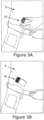
- Figures 3A-B show an examples of adhering the dispensing patch unit (10) to the skin (5) of a patient.
- Figure 3A shows adherence of the dispensing patch unit (10) to the skin (5).
- Figure 3B shows the adhered dispensing patch unit (10) being ready for operation.
- a cradle unit (20) can be adhered first to the skin (5) and the dispensing patch unit (10) can be then connected to and disconnected from the cradle unit (20) upon patient's discretion.
- Figure 4A shows the cradle unit (20) adhered to the patient's body.
- Figure 4B shows the connection of the dispensing patch unit (10) to the cradle unit (20).
- Figure 4C shows the dispensing patch unit (10) after it has been connected to the cradle unit (20), being ready for operation.
- Figures 5A-D shows attachment of the dispensing patch unit (10) to the patient using a dedicated carrier unit (30).
- Figure 5A shows attachment of the carrier unit (30) to the skin (5).
- Figure 5B shows the adhered carrier unit (30).
- Figure 5C shows the connection of the dispensing patch unit (10) to the carrier unit (30).
- Figure 5D shows the dispensing patch unit (10) connected the carrier unit (30) and ready for operation.
- the cradle unit (30) can be attached the body of the patient at any desired location.
- the carrier unit (30) can be connected to the dispensing unit (10) prior to the cradle unit being adhered to skin (5) of the patient.
- Figures 6A-B show modes of operation of the dispensing patch unit (10).
- the patient can operate the dispensing patch unit (10) either using the remote control unit (40) (shown in Figure 6A ) or using one or more buttons (15) located on the dispensing patch unit (10), as shown in Figure 6B .
- the remote control unit (40) can be for example a dedicated remote controller, a cellular phone, a Personal Data Assistant ("PDA”), a watch, a personal computer (“PC”), a laptop, an iPod or any other electronic device suitable for operating the dispensing patch unit.
- PDA Personal Data Assistant
- PC personal computer
- laptop an iPod
- the remote control unit can communicate with the dispensing patch unit via wireless communication as well as any other suitable methods, for example induction, RF transmission, IR transmission etc., or a wired communication.
- Communication between the remote control unit and the dispensing patch unit (10) can be unidirectional (i.e., one-way communication) or bi-directional (i.e., two-way communication).
- the remote control unit may include a glucose sensor (not shown in Figures 6A-B ), which is coupled to the remote control unit.
- the sensing of glucose concentration levels can be carried out by various sensing techniques, such as, electrochemical, optical or the like.
- a blood sample of the patient can be used in association with a conventional test strip that is inserted into a dedicated port, which is located in the remote control unit.
- Figures 7A-C show the dispensing patch unit (10) having two parts: a reusable part (100) and a disposable part (200).
- Figure 7A shows the reusable part (100) having a body portion (101) and a separate cover portion (102).
- Figure 7A also shows the disposable part (200) that can be configured to be smaller in size than the reusable part (100) so that it can be disposed inside the reusable part (100).
- Figure 7B shows the insertion of the disposable part (200) into the reusable part (100).
- the cover portion (102) is removed from the reusable part (100), i.e., it is detached from the body portion (101).
- the disposable part (200) is a cassette that can enter the cavity of the body portion (101) of the reusable part (100).
- Figure 7C shows the disposable part (200) disposed within the body portion (101) of the reusable part (100) and the cover portion (102) is re-attached to the body portion (101) and is closed.
- Dispensing patch unit (10) operation is possible only when the cassette-like disposable part (200) is properly positioned within the body portion (101).
- the cassette-like disposable part (200) and the body portion cavity (101) are configured to permit smooth sliding of the disposable part (200) into the body portion (101).
- Figures 8A-C show an arrangement wherein the body portion (101) and the cover portion (102) of the reusable portion (100) are joined by a hinge or a pivot (103) to enable pivoting of the cover portion (101).
- Figure 8a shows the closed reusable part (100) (on the left side of Figure 8A ) and opened reusable part (100) (on the right side of Figure 8A ) and the disposable part (200) (on the bottom of Figure 8A ).
- the pivot (103) is disposed on the right side of the reusable part (100).
- the pivot (103) can be disposed on either side of the reusable part (100) and can be designed to be disposed along the entire length of one side of the reusable part (100).
- Figure 8B shows insertion of the disposable part (200) into the body portion (101) of the reusable part (100).
- the cover portion (102) is swung open, thereby exposing interior of the body portion (101) and the disposable part (200) is inserted into the body portion (101). Subsequent to insertion, the cover (102) is closed.
- Figure 8C shows the disposable part (200) being disposed within the reusable part (100), and the cover (102) being closed.
- Figures 9A-D show additional detail of an exemplary arrangement of the disposable part (200) and a reservoir (220) during filling and priming procedures.
- Figure 9A shows components of the disposable part (200), which include a reservoir (220), a filling port (213), a delivery tube (230), and a battery (240).
- the filling port (213) is in fluid communication with the reservoir (220) and allows filling of the reservoir (220) with therapeutic fluid, e.g., insulin.
- the reservoir (220) is in fluid communication with the delivery tube (230), through which therapeutic fluid is delivered to an exit port (210) for further deliver to the patient via, for example, a cannula (not shown in Figures 9A-D ).
- the filling port (213) includes a blocking device, such as a rubber septum, that prevents escape of fluid from the reservoir (220) via the filling port (213).
- the battery (240) is coupled outside of the reservoir (220) and powers up the device (10).
- a stator (not shown in Figure 9A ) can be disposed in the reusable part (as illustrated in Figures 10A-C below) as opposed to being disposed in the disposable part of the device (10).
- the disposable part (200) located within the body portion (101) of the reusable part (100) can be without a housing as the housing of the reusable part protects disposable part and its components.
- a need for a single reusable housing can be a major cost reduction factor, thereby significantly lowering the cost of manufacturing the device (10) as well as ultimate cost to the consumer.
- at least a portion of the reusable part's (100) housing can be transparent to allow the patient to continuously monitor level and/or content of the fluid inside the reservoir (220).
- Figures 9B-D show filling and priming procedures.
- Figures 9B-C show reservoir (220) being filled with a syringe (215) through the filling port (213).
- an adapter (not shown in Figures 9A-D ) can be used to connect the syringe (215) and the filling port (213).
- Figure 9D shows a priming procedure, which is performed subsequently to filling the reservoir (220).
- the disposable part (200) is held in an upright position and the fluid pressure created by the user pressing on the plunger of the syringe, forces air bubbles/pockets out of the reservoir (220) and the delivery tube (230) filling.
- the priming procedure is performed until the fluid begins to drip from the exit port (210), as shown in Figure 9D .
- Figures 10A-C show in detail a connection of the reusable and disposable parts.
- Figure 10A shows the reusable part (100) and its components.
- the components include a linear positive displacement pump structure that is composed of a rotary wheel (110) with rollers (not shown in Figure 10A ), a motor (120) with gear(s) (not shown in Figure 10A ), a stator (190) and a printed circuit board (“PCB”) (130).
- the PCB (130) is coupled to the motor (120), which forces rotation of the rotary wheel (110).
- the rollers disposed inside the rotary wheel interact with the stator (190).
- the stator (190) can be disposed within the cover (102), whereas the remaining components of the linear positive displacement pump can be disposed inside the body portion (101) of the reusable part (100).
- the stator (190) is further coupled to a spring (191), which is, in turn, coupled to the cover (102).
- the spring (190) creates tension and allows the stator (190) to press against the delivery tube (230), as shown in Figure 10C , when the disposable part (200) is inserted into the reusable part (100) and the cover (102) is closed.
- the reusable part (100) further includes two buttons (15) that allow manual operation of the dispensing patch unit (10) (e.g., without the remote control unit (40)).
- the function of the buttons (15) can vary and can include turning on/off the device (10), programming/causing the device (10) to inject a bolus dose and/or basal dosage of therapeutic fluid (e.g., insulin) to the patient, or any other function.
- Each button (15) can be assigned its own function.
- the two buttons can be assigned with the same function (e.g. injection of a bolus dose) for safety reasons, preventing unintentionally pressing.
- FIG 10B shows the disposable part (200) being inserted into the reusable part (100).
- the cover (102) is swung open using hinge/pivot (103) and the interior portion of the body (101) is exposed.
- the disposable part (200) is then inserted inside the body portion (101).
- the battery (240) connects to the PCB (130) using electrical contacts (119) and the delivery tube (230) overlays the rotary wheel (110), as illustrated in Figure 10B .
- the device (10) can be powered up.
- Figure 10C shows the dispensing patch unit (10) subsequent to placement of the disposable part (200) within the body portion (101) of the reusable part (100) and after closing the cover portion (102).
- the battery (240) is electrically connected to the board (130) and power is supplied for energizing electronic components and the rotary wheel (110).
- the rotary wheel (110) is juxtaposed (i.e., being placed close together or side-by-side) with the stator (190) (supported by the spring (191)) in way that it squeezes the delivery tube (230) against the wheel (110) allowing peristaltic pumping of the fluid.
- stator (190) within the cover portion (102) of the reusable part provides accuracy and reliable interaction between the rotary wheel (110), the delivery tube (230) and the stator (190). It further eliminates inaccuracies due to assembly and manufacturing tolerances.
- the exit port (210) can be configured to protrude outside the reusable part (100), as illustrated in Figure 10C .
- therapeutic fluid is being pumped from the reservoir (220) into the delivery tube (230), wherein a portion of the delivery tube (230) is being placed between the stator (190) and the rotary wheel (110), and further delivered to the exit port (110) for further delivery to the patient via a cannula.
- Various rotation speeds/frequencies of the rotary wheel (110) and/or rollers disposed within the rotary wheel (110) along with the pressure applied by the stator (190) can determine the amount of therapeutic fluid delivered to the patient (e.g., basal vs. bolus doses).
- Figures 11A-D show an exemplary arrangement of the dispensing patch unit (10) sealing mechanism.
- Figure 11A shows the disposable part (200) including two gaskets (e.g., rubber O-rings): an upper gasket (104) and a lower gasket (105).
- the gaskets (104) and (105) can be disposed around portions of the reservoir (220) as well as potions of the delivery tube (230). Further the gaskets (104) and (105) can be configured to match the perimeter of the body portion (101) and the cover (102).
- Figure 11B shows disposable part (200) and the reusable part (100) being connected.
- the gaskets (104) and (105) maintain sealing of the dispensing patch unit (10) after positioning the disposable part (200) within the reusable part (100) and after pivoting the cover portion (102) to close the body portion (101).
- Figure 11C shows the dispensing patch unit (10) when the body portion (101) is opened.
- Figure 11D shows the dispensing patch unit (10) with the body portion (101) closed by the cover portion (102). Because the gaskets (104) and (105) match the perimeters of the body portion (101) and the cover (102), the dispensing patch unit (10) is completely sealed and fluid delivery is allowed from the reservoir (220) through the exit port (210).
- the buttons (15) can become operable upon closing of the cover (102), which insures that a sealed connection between the cover (102) and the body portion (101) is created.
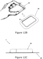
- Figures 12A-H shows the dispensing patch unit (10) attached to the body of the patient using a carrier unit (30).
- the carrier unit (30) is a frame with an adhesive that connects to the skin (5). The adhesive can be disposed on the bottom portion of the frame.
- the carrier unit (30) serves as a carrier for the dispensing patch unit (10) and allows connection and disconnection therebetween.
- Figures 12A-B show connection of the dispensing patch unit (10) to the carrier unit (30).
- the frame of the carrier unit (30) further includes a border (14) that surrounds an area configured to accommodate placement of the dispensing unit (10), as illustrated in Figures 12C-D.
- Figures 12C-D show the dispensing patch unit (10) connected to the carrier unit (30).
- the dispensing patch unit (10) and the carrier unit (30) constitute the fluid delivery device (1).
- the dispensing unit (10) can be secured to the carrier unit (30) by way of snap-on or any other suitable mechanisms.
- Figures 12E-F show how the device (1) is being adhered to the skin (5).
- the adhesive layer (not shown in Figures 12E-F ), is secured to the skin (5) of the patient, thereby securing the carrier unit (30) to the skin of the patient.
- the adhesive layer can allow multiple attachments (i.e., multi-use adhesive) or a single-use attachment (i.e., a single use adhesive).
- Figures 12G-H are a side view and a perspective view, respectively of the device (1) being affixed to the skin (5).
- FIGs 13A-B show another exemplary dispensing patch unit (10), where the disposable unit (200) can be directly coupled to the carrier portion, which is, in turn, secured to the skin of the patient.
- a carrier portion (202) is attached to the disposable part (200).
- the disposable part (200) (for example, with a unitary carrier) can be received, at least in part, within the reusable part (100). In some arrangements, the unit (10) cannot operate without reusable part being attached to the disposable part (200).
- One of the problems with conventional adhesives is that most of them are designed for a single-use only, as such, adherence of the reusable part's (100) components to the user's skin may be undesirable.
- One of the advantages of the arrangement shown in Figures 13A-B is that it reduces a number of components in the system, provides the user with a simple and efficient way to attach the device, as well as reduces the cost of manufacturing the device and the ultimate cost to the user.
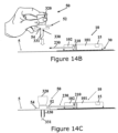
- Figures 14A-D show an exemplary usage of an infusion set together with the dispensing patch unit (10).
- Figure 14A shows the dispensing patch unit (10).
- the delivery tube (230) extends from the dispensing patch unit (10) to an insertion site on the body of the patient (not shown in Figure 14A ).
- the insertion site can be located outside the area of the skin which is covered by the adhered carrier unit (30) (as shown in Figures 14B-D ).
- Figure 14B shows the assembled dispensing patch unit (10) adhered to the skin (5) using a carrier unit (30).
- the delivery tube (230) protrudes away from the unit (10).
- Figure 14B further illustrates an infusion set (50).
- the infusion set (50) includes a hub (54), a connecting tube (52), a cannula (330) and a penetrating member (320).
- the connecting tube (52) is coupled to the hub (54).
- the penetrating member (320) can include a needle or any other penetrating instrument (331) that pierces the skin of the patient at a desired location (i.e., the insertion site).
- penetrating member (320) along with the needle (331) are coupled to the hub (54) and the needle (331) is placed through the cannula (330) and protrudes away from the cannula (330).
- Figure 14c shows the dispensing patch unit (10) being adhered to the skin (5) of the patient and further connected to the infusion set (50).
- the connecting tube (52) is coupled to the delivery tube (230) and then the needle (331) of the penetrating member (320) pierces the skin (5) at the insertion site and allows insertion of the cannula (330) with the needle (331) being disposed in the cannula (330), as illustrated in Figure 14C .
- the piercing of the skin may take place prior to connection of the tubes (52) and (320).
- therapeutic fluid e.g., insulin
- the penetrating member (320) is withdrawn from the hub (54) leaving the cannula (330) subcutaneously immersed beneath the skin (5), as illustrated in Figure 14D .
- the cannula (330 is in fluid communication with the reservoir (220) located within the dispensing patch unit (10) via the tubes (52) and (230).
- the hub (54) may have an adhesive strip on its bottom portion that allows adhering of the hub to the skin (5) once the skin is pierced by the penetrating member (320).
- the device (10) can become operational only upon detection of a connection of the tubes (52) and (230) and/or removal of the penetrating member (320) from the hub (54).
- Figures 15A-17C illustrate exemplary embodiments of the invention showing connection of the reservoir (220) to the cannula (330) using a well-arrangement (60) and a penetrating cartridge (62).
- a well-arrangement 60
- a penetrating cartridge 602.
- the well-arrangement (60) allows the insertion site to be located underneath the dispensing unit (10) and/or the carrier unit (30) instead of being located outside, as illustrated in Figures 14A-D .
- the well-arrangement (60) further prevents accidental disconnections of the delivery tube (230) from the connecting tube of the infusion set (50), shown in Figures 14A-D .
- Figure 15A shows an exemplary disposable part (200) that includes the battery (240), the reservoir (220) and the exit port (210).
- the exit port (210) includes the well-arrangement (60).
- the well-arrangement (60) is in fluid communication with the reservoir (220) via the delivery tube (230).
- Figure 15B shows the entire dispensing unit (10), wherein the reusable and disposable parts are coupled together and the cover portion (102) is being closed.
- the reservoir (220) is configured to supply therapeutic fluid to the well-arrangement (60) via the delivery tube (230) that is being squeezed by the rotary wheel (110) and the stator (190).
- Figure 15C is an enlarged cross-sectional view of the well-arrangement (60) taken along line A-A.
- the well-arrangement (60) includes a tube connector extension (69) that is connected to the delivery tube (230) using a snap-fit, Luer-lock, or any other type of connection.
- the extension (69) includes a plurality of teeth (61) that prevent slippage of the tube (230) when the tube (230) is fitted over the extension (69), as shown in Figure 15C .
- the well-arrangement (60) further includes a housing (65) that includes a bore (64).
- the bore (64) can be a closable channel that is in fluid communication with the delivery tube (230) when the tube (230) is fitted over the extension (69).
- Such fluid communication is provided by a channel (67) disposed within the housing (65).
- the bore (64) can have a cylindrical, square, oval, or any other suitable cross-section.
- the bore (64) further allows insertion of a penetrating cartridge including cannula or other devices carrying a cannula or any other fluid delivery device/channels.
- the well-arrangement (60) is in fluid communication with the exit port (210), through which a penetrating member carrying the cannula is inserted for delivery of the fluid to the patient.
- Figure 16A shows the penetrating cartridge (62) having a body portion (63), the cannula (330), a self-sealable septum (313).
- the penetrating cartridge (62) further includes a channel (319) that extends from the top of the body portion (63) into the cannula (330).
- the channel (319) accommodates placement of a penetrating member (320) (shown on the right side of Figure 16A ).
- the self-sealable septum (313) is configured to seal the channel (319) when the penetrating member (320) is removed from the cartridge (62).
- the penetrating member (320) is composed of a dagger (321) having a sharp end (327) and a grip (322).
- the penetrating member (320) is adapted to pierce the surface of the skin (5).
- Figure 16B shows the penetrating member (320) inserted into the penetrating cartridge (62).
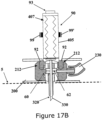
- Figures 17A-C show insertion and subcutaneous placement of the cannula (330) into the body of the patient.
- the insertion and subcutaneous placement of the cannula (330) can be performed using an insertion device, also referred-to as an inserter.
- Figure 17A is a cross-sectional view of an exemplary inserter (90) .
- the inserter (90) includes a hollow housing (405) that accommodates placement/loading of the penetrating member (320).
- the housing (405) further includes a releasable spring (407) that interacts with the housing (405) to release the penetrating member (320) into the well-arrangement (60) and stopper mechanism, for example constraints (99 and 99') that prevents slippage/misfiring of the penetrating member (320).
- the housing (405) further includes projections (92) that interact with corresponding recesses (212) created in the well-arrangement (60). The interaction between projections (92) and recesses (212) further secures the housing (405) that is loaded with the penetrating member (320) to the housing of the well-arrangement (60).
- the delivery tube (230) can be coupled to the well-arrangement (60) prior to insertion of the penetrating member (320). In some embodiments, such coupling can take place after insertion of the penetrating member (320).
- FIG 17B shows cannula (330) being inserted into the subcutaneous tissue.
- insertion is accomplished by securing the housing (405) that is loaded with the penetrating member (320) to the housing of the well-arrangement (60) (using projections (92) and recesses (212)) and then releasing the spring (407), which pushes/fires the penetrating member (320) in a downward direction with regard to the surface of the skin (5).
- the penetrating member's (320) penetrating dagger (321) along with the cannula (330) pierce the skin (5) and enter the subcutaneous tissue of the patient.
- the spring (407) release is accomplished using a button (93) disposed at the top of the housing (405), which removes the constraints (99 and 99') allowing the releasing of the spring (407) and thus the firing of the penetrating member (320).
- a button (93) disposed at the top of the housing (405), which removes the constraints (99 and 99') allowing the releasing of the spring (407) and thus the firing of the penetrating member (320).
- the removal of the penetrating member (320) can be done manually by pulling the housing (405) in an upward direction.
- the self-sealing septum (313) seals the channel (319), thus, preventing any fluid leakage and/or contamination.
- the cannula (330) remains in the subcutaneous compartment. The insertion of the penetrating member (320)/cannula (330) into the insertion site can be done at any desired angle.
- Figures 18A-21C illustrate exemplary embodiments of the invention where the connection of the dispensing patch unit (10) to the skin (5) is done using a cradle unit.
- An example of the cradle unit is disclosed in a commonly-owned U.S. Provisional Patent Application Serial No. 60/876,679, filed December 22, 2006 , U.S. Patent Application No. 11/963,481, filed December 21, 2007 , and International Patent Application WO 2008/078319 , filed December 20, 2007
- the cradle unit includes two parts as follows:
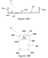
- Figures 18A-D show an exemplary cradle unit, according to some embodiments of the present invention.
- Figure 18A shows the cradle part (21) that includes a cradle base (300), connecting latches (306(a, b, c)), an opening (307), and anchoring latches (302(a, b, c, d)) for connecting to the dispensing patch unit (10).
- Figure 18A is a side view of the cradle part (21) and, thus, displays only two connecting latches (306) and two anchoring latches (302).
- the latches (302) and (306) are designed to have snap-on arrangement, whereby once the unit (10) is inserted into the cradle part (21), the latches (302) and (306) securely lock the unit (10) and/or its components to the base (300).
- Figure 18B-C are upper and isometric views, respectively, of the cradle part (21) including cradle base (300) and three connecting latches (306) disposed around the opening (307).
- the opening (307) and the latches (306) are configured to receive a cannula cartridge unit (22) shown in Figure 18D .
- the cannula cartridge unit (22) includes a well portion (310), lateral recesses (316), a septum (313), the cannula (330) and the penetrating member (320).
- the lateral recesses (316) are configured to mate with latches (306) and create a snap-fit arrangement, which secures or anchors the cannula cartridge unit (22) to the opening (307).
- the penetrating member (320) pierces the skin (5) (not shown in Figures 18A-D ) and allows insertion of the cannula (330), as discussed above.
- the penetrating member (320) can be removed while retaining the cannula (330) inserted into the subcutaneous tissue.
- the septum (313) seals the top portion of the passageway through which the penetrating member (320) is removed, as discussed above.
- the cannula cartridge unit, (22) is shaped to allow substantially precise fit between the latches (306) and alignment of the cannula (330) along with the penetrating member (320) and the opening (307).
- Figures 19A-D shows connection of the cradle part (21) and the cannula cartridge unit (22), as discussed above with regard to Figures 18A-D .
- Figure 19A shows the cradle part (21) attached to the patient skin (5). The attachment can be done using adhesives or using any other means. As can be understood by one skilled in the art, the adhesive layer can be disposed on the side of the cradle base (300) that faces the skin (5).
- Figure 19B shows the connection of the cannula cartridge unit (22) to the cradle part (21) using the latches (306) and the recesses (316).
- FIG 19C shows the cannula cartridge unit (22) connected to the cradle part (21).
- Figure 19D shows the removal of the penetrating member (320) from the cannula cartridge unit (22).
- the cradle part (21) is adhered to the skin (5) and the cannula (330) remains in the body.
- the self-sealable septum (313) of the well (310) allows repeated connection/disconnection with the connecting lumen (250) of the dispensing patch unit (10).
- the self-sealable septum (313) also prevents leaking and entrance of contaminants.
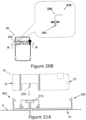
- Figures 20A-21C show connection and disconnection of the dispensing patch unit (10) to and from the cradle unit (21).
- Figure 20A is a top view of the dispensing patch unit (10) including the reusable part (100) and the disposable part (200) and being coupled to the cradle unit (21).
- Figure 20A further illustrates that the disposable part (200) includes the exit port (210), a connecting lumen (250), the delivery tube (230) and the reservoir (220).
- the connecting lumen (250) is disposed at the exit port (210).
- the delivery tube (230) is connected to the connecting lumen (250) that provides fluid communication between the reservoir (220), the delivery tube (230) and the cannula (330) (not shown in Figure 20A ).
- Figure 20b further illustrates the detail of the connecting lumen (250) being rigidly connected to the delivery tube (230).
- the detailed cross-sectional view of the lumen (250) is shown along line B-B.
- Figure 21A shows connection of the dispensing patch unit (10) to the cradle unit (21).
- the latches (302) are configured to secure the unit (10) to the cradle unit (21).
- the unit (10) further includes a plurality of lateral notches/recesses (12) that are configured to mate with the latches (302) upon placement of the unit (10) into the cradle unit (21).
- the connecting lumen (250) pierces the well's self-sealing septum (313) allowing fluid communication between the cannula (330) and the reservoir (220).
- Figure 21b shows the dispensing unit (10) being attached to the cradle unit (21) (i.e., the dispensing unit (10) being in operating mode).
- the connecting lumen (250) pierces the septum (313) of the cradle unit (20) and enters in the cannula (330) maintaining fluid communication between reservoir (220) and cannula (330).
- the lateral notches (12) allow connecting of the dispensing patch unit (10) to the cradle unit (20) by anchoring latches (302).
- Figure 21c shows disconnection of the dispensing patch unit (10).
- the elastically deformable latches (302) are pulled away from the unit's (10) housing and the unit (10) is released from the grip of the cradle unit (21).
- the cradle unit (21) remains adhered to the skin (5) and the cannula (330) also remains in the body.
- the self-sealable septum (313) avoids body fluids leaking and contamination.
- the dispensing patch unit can further include a sensing means (not shown) to measure and monitor body analyte(s) e.g., glucose sensor or continuous glucose monitor (“CGM").
- a dispensing patch unit and sensing means can be capable of operating in one or more of a closed loop, open loop, or a semi-open loop mode.
- An example of such dispensing patch unit with the incorporated sensing means is disclosed in the commonly owned U.S. Patent Applications Serial Nos. 11/706,606, filed February 14, 2007 , and 11/963,481, filed December 21, 2007
- an analyte concentration is sensed by a sensor and determined by a processor and the processor commands a dispensing apparatus to dispense one or more therapeutic fluids to the human body based on the determined concentration.
- the sensing and dispensing functions are not linked.
- a device/system which operates in this mode could indicate a value for the determined analyte concentration, but no feedback control is exercised over the rate of dispensing.
- a user interface or other means by which a user can communicate commands to the device can allow the user to dispense the therapeutic fluid.
- the sensing occurs as noted above for the closed loop mode.
- the device/system can wait for confirmation/action or alternatively it can request such confirmation/action, possibly via some user interface, from a user before dispensing the therapeutic fluid in the amounts that might be needed based on the determined analyte concentration.
Description
- Embodiments of the present invention generally relate to devices for pumping of fluids into a body and, particularly, to a portable pump (for example, a patch) that can be coupled or adhered to the skin of a patient. The fluid pumping device is provided with a pump mechanism deployed within a housing having two relatively displaceable parts. The pump mechanism can be enabled or disabled upon displacement of the housing parts.
- Medical treatment of several illnesses requires continuous drug infusion into various body compartments, such as subcutaneous and intra-venous injections. For example, diabetes mellitus patients require the administration of varying amounts of insulin throughout the day to control their blood glucose levels. In recent years, ambulatory portable insulin infusion pumps have emerged as superior alternatives to multiple daily injections of insulin using a syringe. These pumps, which deliver insulin at continuous basal rates, as well as, in bolus volumes, were developed to liberate patients from repeated self-administered injections, and allow them to maintain a near-normal daily routine. Both basal and bolus volumes must be delivered in precise doses, according to individual prescription, since an overdose of insulin could be fatal. Therefore, insulin injection pumps must feature high reliability, preventing delivery of any unintentional insulin excess.
- Several ambulatory insulin infusion pumps are currently available on the market. Mostly, these devices have two parts: a durable portion, containing a dispensing means, a controller and electronics, and a disposable portion containing a reservoir for insulin, a needle assembly (cannula and penetrating member), and a fluid delivery tube altogether named "infusion set". Usually, the patient fills the reservoir, attaches the infusion set to the exit port of the reservoir, and then inserts the reservoir into the pump housing.
- After purging air out of the reservoir, the delivery tube and the needle, the patient inserts the needle assembly, at a selected location on the body, and then upon subcutaneous insertion of the needle of the penetrating member, withdraws the penetrating member, while leaving the cannula inserted. To avoid irritation and infection, the subcutaneous cannula must be replaced and discarded after two to three days, together with the empty reservoir.
- Examples of a first generation disposable syringe-type reservoir and tubes were disclosed in
U.S. Patent No. 3,631,847 to Hobbs ,U.S. Patent No. 3,771,694 to Kaminski , and laterU.S. Patent No. 4,657,486 to Julius , andU.S. Patent No. 4,544,369 to Skalcoon . The driving mechanism of the dispensing means of these devices is a screw thread plunger, which controls the programmed movement of a syringe piston. These devices represent a significant improvement over multiple daily injections, but all suffer from several drawbacks. The main drawbacks are their large sizes and weight of the devices, which are a result of their spatial configurations and relatively large driving mechanisms of the syringe and piston. The relatively bulky device had to be carried in a patient's pocket or attached to the belt. Consequently, the fluid delivery tube was long, usually longer than 60cm, in order to allow needle insertion in remote sites of the body. These uncomfortable bulky devices with a long tube were rejected by the majority of diabetic insulin users because they disturb regular activities, such as sport activities and swimming. Furthermore, the effect of the image projected on a teenager's body is unacceptable. In addition, the fluid delivery tube excludes some optional remote insertion sites, like the buttocks and the extremities. To avoid the tubing limitations, a new concept of a second generation was proposed. - This new concept related to a skin adherable device with a housing having a bottom surface adapted for contact with the patient's skin, a reservoir contained within the housing, and an injection needle adapted for communication with the reservoir. This skin adherable device was designed to be disposed every 2-3 days similarly to the currently available pump infusion sets.
- This design was disclosed in
U.S. Patent No. 4,498,843 to Schneider ,U.S. Patent No. 5,957,895 to Burton ,U.S. Patent No. 6,589,229 to Connelly , andU.S. Patent No. 6,740,059 to Flaherty . Additional configurations of conventional skin adherable pumps are disclosed inU.S. Patents Nos. 6,723,072 and6,485,461 . - In these patents, the pump includes one piece and has to be adhered to the patient's skin for the entire usage duration while the needle that emerges from the bottom surface of the device is being fixed to the device housing.
- These second-generation skin adherable devices have several limitations:
- o They waste insulin -- a single-piece device must be disposed after each pump replacement (i.e., every 2-3 days) including unused insulin. Further, in cases of site misplacement (scar tissue, bleeding, cannula kinking, etc.), the entire device including fully filled insulin reservoir must be disposed.
- ∘ They are expensive -- the entire device including relatively expensive parts must be disposed after each pump replacement. Thus, the production cost is high and the final product price far exceeds Medicare allowable payments.
- ∘ They are bulky and heavy -- the automatic insertion mechanism employed in these devices occupies substantial volume, as disclosed in for example,
U.S. Patent No. 6,699,218 . Thus, although the insertion process ends, the patient must carry the heavy and bulky insertion mechanism (springs, etc.) for the entire usage duration. - An attempt to eliminate these drawbacks included a two-piece conventional skin adherable dispensing patch unit having two parts:
- ∘ A reusable part -- a first housing that contains the driving and pumping mechanism, electronics and other relatively expensive components.
- ∘ A disposable part -- a second housing that contains components such as reservoir, tubes and batteries, that can last until reservoir is emptied, i.e., usually a few days.
- This concept provides a cost-effective device and allows diverse usage of the device, e.g., the use of various reservoir sizes, various needle and cannula types and effecting of versatile operational modes. There are various applicable types of pumping mechanisms for the two-piece device configuration.
- Conventional delivery mechanisms include linear positive displacement pumping mechanism having a rotary wheel with rollers, a stator and a resilient delivery tube. The tube is located between the rotary wheel and the stator.
- While the rotary wheel rotates, the rollers continuously "squeeze" the tube in one direction only, displacing the fluid within the tube from the reservoir towards the exit port provided at the housing. The stator is biased by a spring and is pressed towards the delivery tube against the rotary wheel, preventing coarse movements of the tube.
- The conventional delivery mechanism devices suffer from several limitations:
- o The devices are expensive -- each part (disposable and/or reusable) is enclosed within a different housing. Since the disposable part should be often replaced e.g., every 3 days, its housing becomes a major cost factor. Additional cost increase occurs when the stator is configured to be a part of the disposable part.
- ∘ Sealing hurdles -- it is very difficult to manufacture the two parts with a perfect connection due to tolerances and inaccuracies of assembly causing imperfect sealing in parts' connection.
- ∘ Fluid delivery inaccuracies -- delivery tube, rotary wheel and stator are not necessarily located in the same part of the dispensing patch unit (e.g., the stator and the delivery tube are located in the disposable part, while the rotary wheel is located in the reusable part). When connecting the disposable and reusable parts together, the matching of these three components may be mechanically imperfect due to manufacturing tolerances and inaccuracy of assembly. This can cause inaccurate fluid delivery.
- ∘ The devices are not safe -- an initial connection of the reusable part and the disposable part is done by the patient and not in the factory. Therefore a fault connection may happen leading to drug over- or under-dosing.
- ∘ Status of reservoir content -- since the reservoir is located within the disposable housing, the patient is not aware of fluid status in the reservoir during the priming procedure, i.e., while filling the reservoir, the patient is not aware of the current amount of fluid disposed within the reservoir.
- Another drawback of existing skin adherable drug infusion devices is associated with the process of insertion. In cases of fault insertions, the whole device must be discarded including the fluid within (i.e., pre-used insulin). This process is cumbersome and costly,
- In view of the foregoing, it would be desirable to provide improved devices for sustained medical infusion of fluids.
-
US 2006/0122577 relates to a modular drug delivery system, and discloses a fluid delivery device according to the pre-amble of appendedindependent claim 1. -
US 2006/0264835 relates to a skin mountable medical device comprising a transcutaneous device unit and a reservoir unit. -
EP 1177802 relates to a wearable, self-contained drug delivery infusion device. -
WO 02/068015 US 5984894 relates to an infuser for infusing a liquid from a reservoir. -
WO 2008/078318 , forming part of the state of the art for the purposes of Article 54(3) EPC, discloses a device including a skin adherable cradle for retaining a therapeutic fluid dispenser for delivering a therapeutic fluid to a user. -
WO 2005/002649 relates to a portable drug delivery device having an encapsulated needle. -
US 2006/264894 relates to an infusion device including a durable housing portion and a separable disposable portion. -
WO 98/10807 -
WO 2007/052277 relates to a modular portable infusion pump comprising a first separate reusable unit, a second separate depletable unit and a third separate disposable unit having a cannula. -
WO 2006/108809 relates to a medical skin mountable device comprising a transcutaneous device unit and a process unit. - In accordance with the present invention, there is provided a fluid delivery device as defined in appended
independent claim 1. Embodiments of the invention are defined in appended claims which depend fromindependent claim 1. - Embodiments of the present invention provide improved devices for sustained medical infusion of fluids.
- In some embodiments, a fluid delivery device is provided with a configuration that provides separation between the infusion device and the drug delivery mechanism (i.e., needle, cannula, array of micro-needles).
- In some arrangements, a fluid delivery device is provided that is configured as a miniature portable programmable fluid dispensing patch unit that has short external tubing or substantially no external tubing, and that can be adhered to the body at any desired location. As used herein, the fluid dispensing patch unit sometimes will be referred to as a dispensing patch or dispensing unit. As can be understood by one skilled in the art, such reference is provided here for exemplary, non-limiting purposes.
- In some arrangements, a fluid delivery device includes a dispensing patch unit and a carrier unit, which can be adhered to the skin. The dispensing patch unit can be connected to the carrier unit. The carrier unit retains the dispensing patch unit attached to the body without directed adherence.
- In some embodiments, a fluid delivery device includes a dispensing patch unit that can be disconnected from and reconnected to the patient, thereby allowing temporary removal of the device, in such cases as taking hot bath, sauna, intimacy, etc. Based on the configuration of the device, disconnections and reconnections do not harm various components of the patch (e.g., pumping mechanism and needle), the surrounding tissue and/or the patient.
- In some embodiments, the present invention's device includes a dispensing patch unit and a cradle unit, where the cradle unit is adherable to the skin, and where the dispensing patch unit can be connected to and disconnected from the cradle unit upon patient's discretion.
- In some embodiments, the fluid delivery device has a dispensing patch unit that can be programmed by a remote control unit and/or by buttons provided on the dispensing patch.
- The present invention's device contains a dispensing patch unit that has two parts: a disposable part and a reusable part. Accordingly, relatively expensive components can be disposed within the reusable part (e.g., electronic, driving mechanism, transceiver, etc.) and relatively inexpensive components can be disposed within the disposable part (e.g., reservoir, batteries etc.).
- The present invention's device includes a dispensing patch unit that has two parts, which after connection allow the unified device to have a thin profile.
- The device includes a dispensing patch having two parts: a reusable part and a disposable part. After connection of the two parts, the unified device allows the pumping mechanism, which may be located in the reusable part, to dispense fluid from the reservoir, located in the disposable part.
- The device includes a dispensing patch unit that having two parts and allows accurate, safe and user-friendly connection of the two parts.
- In some arrangements, the device includes a dispensing patch unit having two parts: a reusable part and a disposable part. The reusable part contains a linear positive displacement pumping mechanism including rotating wheel and a stator. After connection of the two parts, the pumping mechanism allows fluid dispensing from the reservoir disposed in the disposable part.
- In some arrangements, the device includes a dispensing patch unit having a reservoir that allows simple filling of the reservoir and during filling, the user is able to observe the fluid disposed within the reservoir. In some embodiments, the filling of the reservoir may be carried out by a dedicated adapter.
- In some embodiments, the device includes a dispensing patch unit having two parts: a reusable part and a disposable part, where the battery is disposed within the disposable part. Thus, this avoids patient involvement in handling and replacement of the battery.
- In some embodiments, the dispensing patch unit includes two parts: a reusable part and a disposable part, where the seal between the parts, subsequent to their connection, is complete and does not affect the device's function.
- In some embodiments, the device includes a dispensing patch unit that allows manual needle insertion or automatic needle insertion using the aim of a dedicated inserter.
- Some embodiments of the present invention relate to a fluid delivery device that includes a dispensing patch unit that can be adhered to the skin of a patient and that delivers therapeutic fluid to the body. In the following description, this unit can sometimes be referred to as: skin adherable dispensing patch unit, dispensing patch, infusion patch, dispensing unit, patch unit or interchangeable dispenser.
- Some embodiments of the invention are implemented as a miniature portable programmable fluid dispenser. The dispenser may be adhered to the skin at any desired location. Fluid flow instructions can be programmed manually by pushing buttons located on the patch or be remotely transmitted to the dispensing patch unit by the remote control unit. In some embodiments, the dispenser is a single unit having two parts: a reusable part and a disposable part. The dispenser can be adhered directly to the skin, using a cradle unit.
- In some embodiments, the dispensing patch unit includes a reservoir, a driving mechanism which may include for example an electrical DC, a stepper motor, a shape memory alloy actuator, or the like, and a pumping mechanism, such as a peristaltic pump, a syringe/piston pump, or the like. The dispensing patch unit may also include a power supply and electronics. In some arrangements, the dispensing patch unit employs a linear positive displacing pump composed of a rotary wheel and rollers that squeeze a delivery tube against a stator displacing fluid from a reservoir towards the body. The connection of the two parts is done by inserting the disposable part into the reusable part. Closing the reusable part over the disposable part with a cover may establish electrical connections and a power supply for energizing electronic components and the rotary wheel. In addition, the rotary wheel may be coupled to the stator that squeezes the delivery tube against the rotary wheel allowing fluid pumping.
- Fluid delivery into the subcutaneous compartment may be done using a soft cannula. The cannula may be inserted either manually or by using a dedicated inserter followed by penetrating member withdrawal.
- In some arrangements, communication between the patch unit and the cannula within the subcutaneous compartment can be performed as follows:
- ∘ Directly connecting cannula to a patch unit's exit port;
- ∘ Connecting infusion set (a short tube) to the patch unit either directly or via a luer;
- ∘ Penetrating, via a well portion, a fluid collection element and the skin of the patient using a cannula.
- ∘ Separating the cradle unit that contains cradle and cannula. The user can connect and disconnect the dispensing patch unit from the cradle unit. A short connecting lumen (located in the dispensing patch unit) pierces a self sealed septum (e.g., rubber septum located in the cradle unit).
- In some embodiments, the device can include one or more of the following units and parts:
- 1. A dispensing patch unit containing the driving and pumping mechanisms, a reservoir, a delivery tube and an exit port. In some embodiments, the dispensing patch unit includes two parts as follows:
- i. A reusable part -- containing components that can be used many times, such as, the driving and pumping mechanisms.
- ii. A disposable part -- containing disposable components that can be used until emptying the reservoir, such as, the reservoir, the delivery tube, the exit port. It may contain also a flat sheet with an adhesive layer facing the skin and a connecting means to allow connection of the dispensing patch unit to a cradle unit.
- 2. A cradle unit, containing the following parts:
- i. A cradle part, which is configured as a resilient sheet. Its bottom is coated with an adhesive to enable adherence to the skin. Its upper side includes connecting means for connection to and disconnection from the dispensing unit.
- ii. A cannula and a penetrating member. The penetrating member is removed after insertion. The cannula and the penetrating member may be subcutaneously inserted either manually or with the aid of an inserter. Cannula can be inserted manually or using an inserter as follows:
- 1. Externally to the dispensing unit -- a short external tube connecting the cannula and the exit port of the dispensing patch unit;
- 2. Through a well portion; or,
- 3. Using a component of the cradle part.
- iii. A well portion.
- 3. A remote control unit for programming flow and data acquisition.
- In some embodiments, devices disclosed herein may be used for medical infusion of therapeutic fluids into the body.
- In some embodiments, a device is provided for sustained medical infusion with controlled rate injection of a therapeutic fluid into the body.
- In some embodiments, the present invention's device for medical infusion is thin, has no external tubing and can be adhered to a patient skin (e.g., skin adherable infusion patch).
- In some embodiments, the present invention's skin adherable infusion patch includes a reservoir, a delivery tube and an exit port enabling fluid communication with a subcutaneously inserted cannula through a well portion.
- The skin adherable infusion patch includes two parts: a reusable part and a disposable part. The reusable part can include electronic components and the driving mechanism, and the disposable part can include the reservoir, the delivery tube and the exit port.
- In some arrangements, a system is provided that includes a skin adherable infusion patch unit having two parts. The infusion patch unit may be attached to the skin directly, using a cradle unit.
- In some embodiments, a device is provided that includes a dispensing patch unit that can be disconnected and reconnected.
- In some arrangements, a method for medical infusion is provided that allows infusion of a therapeutic fluid into the patient's body through a flexible, soft subcutaneously insertable cannula. The cannula can be inserted into the patient's body manually by the patient or using a spring loaded inserter.
- In some arrangements, a reliable, safe, accurate and user-friendly system is provided that includes a skin adherable infusion patch unit.
- In some embodiments, a low cost skin adherable infusion patch, according to the present invention, includes two parts: a reusable part and a disposable part, wherein the production cost of the disposable part is low (where the disposable part includes a few relatively inexpensive components).
- In some arrangements, the skin adherable infusion patch has a reusable part and a disposable part, where the disposable part contains a transparent reservoir allowing the patient to see amount of fluid during filling and pump operation.
- In some arrangements, the skin adherable infusion patch includes a reusable part and a disposable part, where the components of the pump are located in the reusable part. Initial adjustments can be performed in the factory and not by the patient, thereby allowing higher accuracy and performance of the fluid pump.
- In some arrangements, the skin adherable infusion patch includes a reusable part and a disposable part, where the connection between the two parts is well-sealed, thereby establishing a water-proof dispensing patch unit that prevents water penetration, leakage or the entrance of contaminants.
- A detailed description of embodiments of the invention will be made with reference to the accompanying drawings, wherein like reference numerals designate corresponding parts in the several figures, and in which:
-
Figure 1 illustrates an exemplary fluid dispensing device including a dispensing unit and a remote control unit, -
Figures 2A-C illustrate an exemplary two-part dispensing unit and disposition of the disposable part within the reusable part, -
Figures 3A-B illustrate an exemplary direct attachment of the dispensing unit onto the body, -
Figures 4A-C illustrate an exemplary adherence of the dispensing unit to the patient's skin using a cradle unit, according to some embodiments of the present invention. -
Figures 5A-D illustrate an exemplary adherence of the dispensing unit to the patient's skin using a carrier unit, -
Figures 6A-B illustrate exemplary operation modes of the dispensing unit, -
Figures 7A-C illustrate an exemplary reusable part containing body and cover, wherein the disposable part can reside within the body portion of the reusable part, -
Figures 8A-C illustrate exemplary reusable part, including a cover, and the disposable part, wherein the cover and body of reusable part are joined by a hinge, -
Figures 9A-D illustrate an exemplary disposable part, during filling and priming procedures, -
Figures 10A-C illustrate exemplary reusable and disposable parts and their connection, -
Figures 11A-D illustrate an exemplary sealing mechanism of the dispensing unit, -
Figures 12A-H illustrate an exemplary adherence of the dispensing unit to the body of the patient using a carrier unit, -
Figures 13A-B illustrate an exemplary carrier portion that is attached to the disposable part and serves as the carrier for the dispensing patch unit, -
Figures 14A-D illustrate an exemplary dispensing device, wherein the delivery tube extends from the dispensing patch unit connected to an infusion set, -
Figures 15A-C illustrate an exemplary dispensing patch unit provided with a well-arrangement, according to some embodiments of the present invention. -
Figures 16A-B illustrate exemplary penetrating cartridge and penetrating member of the dispensing device , according to some embodiments of the present invention. -
Figures 17A-C illustrate an exemplary penetrating cartridge (including cannula) insertion into the well arrangement using an inserter, -
Figures 18A-D illustrate exemplary cradle unit and penetrating cartridge unit, according to some embodiments of the present invention. -
Figures 19A-D illustrate exemplary cross-sectional views of the cradle unit and penetrating cartridge unit and their connection, according to some embodiments of the present invention. -
Figures 20A-B illustrate an exemplary dispensing patch unit with an exit port having a connecting lumen, according to some embodiments of the present invention. -
Figures 21A-C illustrate exemplary cross-sectional views of the connection and disconnection of the dispensing patch unit to and from the cradle unit, according to some embodiments of the present invention. -
Figures 1-6B illustrate a fluid delivery system or device (1) and various possibilities for its attachment to the body.Figure 1 shows the device (1) for medical infusion of therapeutic fluids into the body. The device (1) includes a dispensing unit (10) and a remote control unit (40). As can be understood by one skilled in the art, the dispensing unit (10) can be in the form of any type of dispensing device, such as a dispensing patch, and that the present invention is not limited to a patch. The terms "dispensing unit" and "dispensing patch" will be used throughout the following description interchangeably and have the same meaning. In some embodiments, the remote control unit (40) can include various controls, a processor, and communications capabilities, that can interact and control operation of the dispensing unit (10). The remote control unit (40) can also include a display screen (44) that can display status and other information for the patient (the terms "patient" and "user" are used in this description). The dispensing unit (10) can also include various controls, a processor, and communication capabilities in addition to other components, which are described below. The dispensing unit's (10) components interact with the remote control unit (40) components for operational purposes. - Referring to
Figures 2A-2C , the dispensing patch unit (10) includes a reusable part (100) and a disposable part (200). The reusable part (100) and the disposable part (200) can be connected to each other, as illustrated inFigure 2C . -
Figures 2A-C illustrate connection of the two parts.Figure 2A shows the insertion of the disposable part (200) into the reusable part (100).Figure 2B shows the disposable part (200) disposed within the reusable part (100) and cover portion (102) being closed.Figure 2C shows the dispensing patch unit (10) when the cover portion (102) is closed and the disposable part (200) is inserted within the reusable part (100). -
Figures 3A-B show an examples of adhering the dispensing patch unit (10) to the skin (5) of a patient.Figure 3A shows adherence of the dispensing patch unit (10) to the skin (5).Figure 3B shows the adhered dispensing patch unit (10) being ready for operation. - In another embodiment shown in
Figures 4A-C , a cradle unit (20) can be adhered first to the skin (5) and the dispensing patch unit (10) can be then connected to and disconnected from the cradle unit (20) upon patient's discretion.Figure 4A shows the cradle unit (20) adhered to the patient's body.Figure 4B shows the connection of the dispensing patch unit (10) to the cradle unit (20).Figure 4C shows the dispensing patch unit (10) after it has been connected to the cradle unit (20), being ready for operation. -
Figures 5A-D shows attachment of the dispensing patch unit (10) to the patient using a dedicated carrier unit (30).Figure 5A shows attachment of the carrier unit (30) to the skin (5).Figure 5B shows the adhered carrier unit (30).Figure 5C shows the connection of the dispensing patch unit (10) to the carrier unit (30).Figure 5D shows the dispensing patch unit (10) connected the carrier unit (30) and ready for operation. As can be understood by one skilled in the art, the cradle unit (30) can be attached the body of the patient at any desired location. - The carrier unit (30) can be connected to the dispensing unit (10) prior to the cradle unit being adhered to skin (5) of the patient.
-
Figures 6A-B show modes of operation of the dispensing patch unit (10). The patient can operate the dispensing patch unit (10) either using the remote control unit (40) (shown inFigure 6A ) or using one or more buttons (15) located on the dispensing patch unit (10), as shown inFigure 6B . The remote control unit (40) can be for example a dedicated remote controller, a cellular phone, a Personal Data Assistant ("PDA"), a watch, a personal computer ("PC"), a laptop, an iPod or any other electronic device suitable for operating the dispensing patch unit. - The remote control unit can communicate with the dispensing patch unit via wireless communication as well as any other suitable methods, for example induction, RF transmission, IR transmission etc., or a wired communication. Communication between the remote control unit and the dispensing patch unit (10) can be unidirectional (i.e., one-way communication) or bi-directional (i.e., two-way communication).
- In some arrangements, the remote control unit may include a glucose sensor (not shown in
Figures 6A-B ), which is coupled to the remote control unit. The sensing of glucose concentration levels can be carried out by various sensing techniques, such as, electrochemical, optical or the like. In some arrangements, a blood sample of the patient can be used in association with a conventional test strip that is inserted into a dedicated port, which is located in the remote control unit. -
Figures 7A-C show the dispensing patch unit (10) having two parts: a reusable part (100) and a disposable part (200). -
Figure 7A shows the reusable part (100) having a body portion (101) and a separate cover portion (102).Figure 7A also shows the disposable part (200) that can be configured to be smaller in size than the reusable part (100) so that it can be disposed inside the reusable part (100).Figure 7B shows the insertion of the disposable part (200) into the reusable part (100). To insert the disposable part (200) into the reusable part (100), the cover portion (102) is removed from the reusable part (100), i.e., it is detached from the body portion (101). In some arrangements, the disposable part (200) is a cassette that can enter the cavity of the body portion (101) of the reusable part (100).Figure 7C shows the disposable part (200) disposed within the body portion (101) of the reusable part (100) and the cover portion (102) is re-attached to the body portion (101) and is closed. Dispensing patch unit (10) operation is possible only when the cassette-like disposable part (200) is properly positioned within the body portion (101). To achieve proper matching, the cassette-like disposable part (200) and the body portion cavity (101) are configured to permit smooth sliding of the disposable part (200) into the body portion (101). -
Figures 8A-C show an arrangement wherein the body portion (101) and the cover portion (102) of the reusable portion (100) are joined by a hinge or a pivot (103) to enable pivoting of the cover portion (101).Figure 8a shows the closed reusable part (100) (on the left side ofFigure 8A ) and opened reusable part (100) (on the right side ofFigure 8A ) and the disposable part (200) (on the bottom ofFigure 8A ). As illustrated inFigure 8A , the pivot (103) is disposed on the right side of the reusable part (100). As can be understood by one skilled in the art, the pivot (103) can be disposed on either side of the reusable part (100) and can be designed to be disposed along the entire length of one side of the reusable part (100).Figure 8B shows insertion of the disposable part (200) into the body portion (101) of the reusable part (100). The cover portion (102) is swung open, thereby exposing interior of the body portion (101) and the disposable part (200) is inserted into the body portion (101). Subsequent to insertion, the cover (102) is closed.Figure 8C shows the disposable part (200) being disposed within the reusable part (100), and the cover (102) being closed. -
Figures 9A-D show additional detail of an exemplary arrangement of the disposable part (200) and a reservoir (220) during filling and priming procedures.Figure 9A shows components of the disposable part (200), which include a reservoir (220), a filling port (213), a delivery tube (230), and a battery (240). The filling port (213) is in fluid communication with the reservoir (220) and allows filling of the reservoir (220) with therapeutic fluid, e.g., insulin. The reservoir (220) is in fluid communication with the delivery tube (230), through which therapeutic fluid is delivered to an exit port (210) for further deliver to the patient via, for example, a cannula (not shown inFigures 9A-D ). In some embodiments, the filling port (213) includes a blocking device, such as a rubber septum, that prevents escape of fluid from the reservoir (220) via the filling port (213). The battery (240) is coupled outside of the reservoir (220) and powers up the device (10). - In some arrangements, a stator (not shown in
Figure 9A ) can be disposed in the reusable part (as illustrated inFigures 10A-C below) as opposed to being disposed in the disposable part of the device (10). In some arrangements, the disposable part (200) located within the body portion (101) of the reusable part (100) can be without a housing as the housing of the reusable part protects disposable part and its components. - In some arrangements, a need for a single reusable housing can be a major cost reduction factor, thereby significantly lowering the cost of manufacturing the device (10) as well as ultimate cost to the consumer. In addition, at least a portion of the reusable part's (100) housing can be transparent to allow the patient to continuously monitor level and/or content of the fluid inside the reservoir (220).
Figures 9B-D show filling and priming procedures.Figures 9B-C show reservoir (220) being filled with a syringe (215) through the filling port (213). In some arrangements, an adapter (not shown inFigures 9A-D ) can be used to connect the syringe (215) and the filling port (213). An example of such connection is detailed in a commonly-owned patent applicationU.S. Provisional Patent Application Serial No. 60/838,660, filed August 18, 2006 WO 2008/020447 filed August 16, 2007 . Subsequent to the attachment of the syringe (215) to the filling port (213), the contents of the syringe (215) are transferred to the reservoir (220) (typically, under pressure from pressing on a plunger of the syringe). As stated above, the user may be able to observe the reservoir (220) being filled, as illustrated inFigure 9C . -
Figure 9D shows a priming procedure, which is performed subsequently to filling the reservoir (220). During the priming procedure, the disposable part (200) is held in an upright position and the fluid pressure created by the user pressing on the plunger of the syringe, forces air bubbles/pockets out of the reservoir (220) and the delivery tube (230) filling. The priming procedure is performed until the fluid begins to drip from the exit port (210), as shown inFigure 9D . -
Figures 10A-C show in detail a connection of the reusable and disposable parts.Figure 10A shows the reusable part (100) and its components. The components include a linear positive displacement pump structure that is composed of a rotary wheel (110) with rollers (not shown inFigure 10A ), a motor (120) with gear(s) (not shown inFigure 10A ), a stator (190) and a printed circuit board ("PCB") (130). The PCB (130) is coupled to the motor (120), which forces rotation of the rotary wheel (110). Upon rotation of the rotary wheel, the rollers disposed inside the rotary wheel interact with the stator (190). In some embodiments, the stator (190) can be disposed within the cover (102), whereas the remaining components of the linear positive displacement pump can be disposed inside the body portion (101) of the reusable part (100). The stator (190) is further coupled to a spring (191), which is, in turn, coupled to the cover (102). The spring (190) creates tension and allows the stator (190) to press against the delivery tube (230), as shown inFigure 10C , when the disposable part (200) is inserted into the reusable part (100) and the cover (102) is closed. - The reusable part (100) further includes two buttons (15) that allow manual operation of the dispensing patch unit (10) (e.g., without the remote control unit (40)). The function of the buttons (15) can vary and can include turning on/off the device (10), programming/causing the device (10) to inject a bolus dose and/or basal dosage of therapeutic fluid (e.g., insulin) to the patient, or any other function. Each button (15) can be assigned its own function. In some embodiments, the two buttons can be assigned with the same function (e.g. injection of a bolus dose) for safety reasons, preventing unintentionally pressing.
-
Figure 10B shows the disposable part (200) being inserted into the reusable part (100). The cover (102) is swung open using hinge/pivot (103) and the interior portion of the body (101) is exposed. The disposable part (200) is then inserted inside the body portion (101). Upon insertion, the battery (240) connects to the PCB (130) using electrical contacts (119) and the delivery tube (230) overlays the rotary wheel (110), as illustrated inFigure 10B . Upon connection of the battery (240) to the PCB (130), the device (10) can be powered up. -
Figure 10C shows the dispensing patch unit (10) subsequent to placement of the disposable part (200) within the body portion (101) of the reusable part (100) and after closing the cover portion (102). As stated above, in this position, the battery (240) is electrically connected to the board (130) and power is supplied for energizing electronic components and the rotary wheel (110). Furthermore, the rotary wheel (110) is juxtaposed (i.e., being placed close together or side-by-side) with the stator (190) (supported by the spring (191)) in way that it squeezes the delivery tube (230) against the wheel (110) allowing peristaltic pumping of the fluid. - The location of the stator (190) within the cover portion (102) of the reusable part provides accuracy and reliable interaction between the rotary wheel (110), the delivery tube (230) and the stator (190). It further eliminates inaccuracies due to assembly and manufacturing tolerances.
- The exit port (210) can be configured to protrude outside the reusable part (100), as illustrated in
Figure 10C . This way, upon operation of the device (10), therapeutic fluid is being pumped from the reservoir (220) into the delivery tube (230), wherein a portion of the delivery tube (230) is being placed between the stator (190) and the rotary wheel (110), and further delivered to the exit port (110) for further delivery to the patient via a cannula. Various rotation speeds/frequencies of the rotary wheel (110) and/or rollers disposed within the rotary wheel (110) along with the pressure applied by the stator (190) can determine the amount of therapeutic fluid delivered to the patient (e.g., basal vs. bolus doses). -
Figures 11A-D show an exemplary arrangement of the dispensing patch unit (10) sealing mechanism.Figure 11A shows the disposable part (200) including two gaskets (e.g., rubber O-rings): an upper gasket (104) and a lower gasket (105). In some embodiments, the gaskets (104) and (105) can be disposed around portions of the reservoir (220) as well as potions of the delivery tube (230). Further the gaskets (104) and (105) can be configured to match the perimeter of the body portion (101) and the cover (102). -
Figure 11B shows disposable part (200) and the reusable part (100) being connected. The gaskets (104) and (105) maintain sealing of the dispensing patch unit (10) after positioning the disposable part (200) within the reusable part (100) and after pivoting the cover portion (102) to close the body portion (101).Figure 11C shows the dispensing patch unit (10) when the body portion (101) is opened.Figure 11D shows the dispensing patch unit (10) with the body portion (101) closed by the cover portion (102). Because the gaskets (104) and (105) match the perimeters of the body portion (101) and the cover (102), the dispensing patch unit (10) is completely sealed and fluid delivery is allowed from the reservoir (220) through the exit port (210). In some embodiments, the buttons (15) can become operable upon closing of the cover (102), which insures that a sealed connection between the cover (102) and the body portion (101) is created. -
Figures 12A-H shows the dispensing patch unit (10) attached to the body of the patient using a carrier unit (30). The carrier unit (30) is a frame with an adhesive that connects to the skin (5). The adhesive can be disposed on the bottom portion of the frame. The carrier unit (30) serves as a carrier for the dispensing patch unit (10) and allows connection and disconnection therebetween.Figures 12A-B show connection of the dispensing patch unit (10) to the carrier unit (30). The frame of the carrier unit (30) further includes a border (14) that surrounds an area configured to accommodate placement of the dispensing unit (10), as illustrated inFigures 12C-D. Figures 12C-D show the dispensing patch unit (10) connected to the carrier unit (30). In this configuration the dispensing patch unit (10) and the carrier unit (30) constitute the fluid delivery device (1). The dispensing unit (10) can be secured to the carrier unit (30) by way of snap-on or any other suitable mechanisms.Figures 12E-F show how the device (1) is being adhered to the skin (5). The adhesive layer (not shown inFigures 12E-F ), is secured to the skin (5) of the patient, thereby securing the carrier unit (30) to the skin of the patient. The adhesive layer can allow multiple attachments (i.e., multi-use adhesive) or a single-use attachment (i.e., a single use adhesive).Figures 12G-H are a side view and a perspective view, respectively of the device (1) being affixed to the skin (5). -
Figures 13A-B show another exemplary dispensing patch unit (10), where the disposable unit (200) can be directly coupled to the carrier portion, which is, in turn, secured to the skin of the patient. Referring toFigures 13A-B , a carrier portion (202) is attached to the disposable part (200). One should bear in mind, however that after connection of the reusable (100) and disposable (200) parts, the dispensing patch unit (10) can be adhered directly to the skin (5). The disposable part (200) (for example, with a unitary carrier) can be received, at least in part, within the reusable part (100). In some arrangements, the unit (10) cannot operate without reusable part being attached to the disposable part (200). One of the problems with conventional adhesives is that most of them are designed for a single-use only, as such, adherence of the reusable part's (100) components to the user's skin may be undesirable. One of the advantages of the arrangement shown inFigures 13A-B , is that it reduces a number of components in the system, provides the user with a simple and efficient way to attach the device, as well as reduces the cost of manufacturing the device and the ultimate cost to the user. -
Figures 14A-D show an exemplary usage of an infusion set together with the dispensing patch unit (10).Figure 14A shows the dispensing patch unit (10). The delivery tube (230) extends from the dispensing patch unit (10) to an insertion site on the body of the patient (not shown inFigure 14A ). The insertion site can be located outside the area of the skin which is covered by the adhered carrier unit (30) (as shown inFigures 14B-D ). -
Figure 14B shows the assembled dispensing patch unit (10) adhered to the skin (5) using a carrier unit (30). The delivery tube (230) protrudes away from the unit (10).Figure 14B further illustrates an infusion set (50). The infusion set (50) includes a hub (54), a connecting tube (52), a cannula (330) and a penetrating member (320). The connecting tube (52) is coupled to the hub (54). The penetrating member (320) can include a needle or any other penetrating instrument (331) that pierces the skin of the patient at a desired location (i.e., the insertion site). As shown inFigure 14B , penetrating member (320) along with the needle (331) are coupled to the hub (54) and the needle (331) is placed through the cannula (330) and protrudes away from the cannula (330). -
Figure 14c shows the dispensing patch unit (10) being adhered to the skin (5) of the patient and further connected to the infusion set (50). In some embodiments, the connecting tube (52) is coupled to the delivery tube (230) and then the needle (331) of the penetrating member (320) pierces the skin (5) at the insertion site and allows insertion of the cannula (330) with the needle (331) being disposed in the cannula (330), as illustrated inFigure 14C . In some embodiments, the piercing of the skin may take place prior to connection of the tubes (52) and (320). By piercing the skin (5) of the patient, therapeutic fluid (e.g., insulin) can be delivered to the subcutaneous tissue of the patient via the delivery tube (230), through the connecting tube (52) and into the cannula (330). - Subsequent to the piercing of the skin (5), the penetrating member (320) is withdrawn from the hub (54) leaving the cannula (330) subcutaneously immersed beneath the skin (5), as illustrated in
Figure 14D . As stated above the cannula (330 is in fluid communication with the reservoir (220) located within the dispensing patch unit (10) via the tubes (52) and (230). In some arrangements, in order to further secure the hub (54) and the cannula (330), the hub (54) may have an adhesive strip on its bottom portion that allows adhering of the hub to the skin (5) once the skin is pierced by the penetrating member (320). Further, in some arrangements, the device (10) can become operational only upon detection of a connection of the tubes (52) and (230) and/or removal of the penetrating member (320) from the hub (54). -
Figures 15A-17C illustrate exemplary embodiments of the invention showing connection of the reservoir (220) to the cannula (330) using a well-arrangement (60) and a penetrating cartridge (62). An example of such connection is disclosed in the commonly-owned patent applicationsU.S. Provisional Patent Application Serial Nos. 60/833,110, filed July 24, 2006 60/837,877, filed August 14, 2006 WO 2008/01281 7 , filed July 24, 2007 . The well-arrangement (60) allows the insertion site to be located underneath the dispensing unit (10) and/or the carrier unit (30) instead of being located outside, as illustrated inFigures 14A-D . The well-arrangement (60) further prevents accidental disconnections of the delivery tube (230) from the connecting tube of the infusion set (50), shown inFigures 14A-D . -
Figure 15A shows an exemplary disposable part (200) that includes the battery (240), the reservoir (220) and the exit port (210). The exit port (210) includes the well-arrangement (60). The well-arrangement (60) is in fluid communication with the reservoir (220) via the delivery tube (230). -
Figure 15B shows the entire dispensing unit (10), wherein the reusable and disposable parts are coupled together and the cover portion (102) is being closed. The reservoir (220) is configured to supply therapeutic fluid to the well-arrangement (60) via the delivery tube (230) that is being squeezed by the rotary wheel (110) and the stator (190). -
Figure 15C is an enlarged cross-sectional view of the well-arrangement (60) taken along line A-A. The well-arrangement (60) includes a tube connector extension (69) that is connected to the delivery tube (230) using a snap-fit, Luer-lock, or any other type of connection. In some embodiments, the extension (69) includes a plurality of teeth (61) that prevent slippage of the tube (230) when the tube (230) is fitted over the extension (69), as shown inFigure 15C . The well-arrangement (60) further includes a housing (65) that includes a bore (64). The bore (64) can be a closable channel that is in fluid communication with the delivery tube (230) when the tube (230) is fitted over the extension (69). Such fluid communication is provided by a channel (67) disposed within the housing (65). The bore (64) can have a cylindrical, square, oval, or any other suitable cross-section. The bore (64) further allows insertion of a penetrating cartridge including cannula or other devices carrying a cannula or any other fluid delivery device/channels. As illustrated inFigure 15C , the well-arrangement (60) is in fluid communication with the exit port (210), through which a penetrating member carrying the cannula is inserted for delivery of the fluid to the patient. -
Figure 16A shows the penetrating cartridge (62) having a body portion (63), the cannula (330), a self-sealable septum (313). The penetrating cartridge (62) further includes a channel (319) that extends from the top of the body portion (63) into the cannula (330). The channel (319) accommodates placement of a penetrating member (320) (shown on the right side ofFigure 16A ). The self-sealable septum (313) is configured to seal the channel (319) when the penetrating member (320) is removed from the cartridge (62). The penetrating member (320) is composed of a dagger (321) having a sharp end (327) and a grip (322). The penetrating member (320) is adapted to pierce the surface of the skin (5).Figure 16B shows the penetrating member (320) inserted into the penetrating cartridge (62). -
Figures 17A-C show insertion and subcutaneous placement of the cannula (330) into the body of the patient. In some arrangements, the insertion and subcutaneous placement of the cannula (330) can be performed using an insertion device, also referred-to as an inserter.Figure 17A is a cross-sectional view of an exemplary inserter (90) . The inserter (90) includes a hollow housing (405) that accommodates placement/loading of the penetrating member (320). The housing (405) further includes a releasable spring (407) that interacts with the housing (405) to release the penetrating member (320) into the well-arrangement (60) and stopper mechanism, for example constraints (99 and 99') that prevents slippage/misfiring of the penetrating member (320). The housing (405) further includes projections (92) that interact with corresponding recesses (212) created in the well-arrangement (60). The interaction between projections (92) and recesses (212) further secures the housing (405) that is loaded with the penetrating member (320) to the housing of the well-arrangement (60). This allows more precise insertion of the penetrating member (320) and the cannula (330) to the insertion site, as illustrated inFigure 17B . An exemplary configuration and operation of the inserter (90) is disclosed in the commonly ownedU.S. Provisional Patent Application Serial No. 60/861,345, filed November 28, 2006 WO 2008/065646 , filed November 26, 2007 . As further illustrated inFigure 17A , the delivery tube (230) can be coupled to the well-arrangement (60) prior to insertion of the penetrating member (320). In some embodiments, such coupling can take place after insertion of the penetrating member (320). -
Figure 17B shows cannula (330) being inserted into the subcutaneous tissue. Such insertion is accomplished by securing the housing (405) that is loaded with the penetrating member (320) to the housing of the well-arrangement (60) (using projections (92) and recesses (212)) and then releasing the spring (407), which pushes/fires the penetrating member (320) in a downward direction with regard to the surface of the skin (5). Upon being pushed, the penetrating member's (320) penetrating dagger (321) along with the cannula (330) pierce the skin (5) and enter the subcutaneous tissue of the patient. The spring (407) release is accomplished using a button (93) disposed at the top of the housing (405), which removes the constraints (99 and 99') allowing the releasing of the spring (407) and thus the firing of the penetrating member (320). Once the cannula (330) is inserted into the subcutaneous tissue, the penetrating member (320) along with the housing (405) can be removed, as illustrated inFigure 17C . In some arrangements, upon depression of the button (93), thespring 407 compresses within thehousing 405 thereby pulling the penetrating member (320) (which can be secured to the spring (407) in an upward direction and the constraints (99 and 99') retain the penetrating member (320) within housing (405). In some embodiments, the removal of the penetrating member (320) can be done manually by pulling the housing (405) in an upward direction. Upon removal of the penetrating member (320), the self-sealing septum (313) seals the channel (319), thus, preventing any fluid leakage and/or contamination. Further, once the penetrating member (320) is removed, the cannula (330) remains in the subcutaneous compartment. The insertion of the penetrating member (320)/cannula (330) into the insertion site can be done at any desired angle. -
Figures 18A-21C illustrate exemplary embodiments of the invention where the connection of the dispensing patch unit (10) to the skin (5) is done using a cradle unit. An example of the cradle unit is disclosed in a commonly-ownedU.S. Provisional Patent Application Serial No. 60/876,679, filed December 22, 2006 U.S. Patent Application No. 11/963,481, filed December 21, 2007 WO 2008/078319 , filed December 20, 2007 - In some embodiments, the cradle unit includes two parts as follows:
- 1. The cradle unit provided with
- a. a cradle base.
- 2. The penetrating cartridge unit having:
- a. a well portion;
- b. a cannula; and,
- c. a penetrating member.
-
Figures 18A-D show an exemplary cradle unit, according to some embodiments of the present invention.Figure 18A shows the cradle part (21) that includes a cradle base (300), connecting latches (306(a, b, c)), an opening (307), and anchoring latches (302(a, b, c, d)) for connecting to the dispensing patch unit (10).Figure 18A is a side view of the cradle part (21) and, thus, displays only two connecting latches (306) and two anchoring latches (302). The latches (302) and (306) are designed to have snap-on arrangement, whereby once the unit (10) is inserted into the cradle part (21), the latches (302) and (306) securely lock the unit (10) and/or its components to the base (300). -
Figure 18B-C are upper and isometric views, respectively, of the cradle part (21) including cradle base (300) and three connecting latches (306) disposed around the opening (307). The opening (307) and the latches (306) are configured to receive a cannula cartridge unit (22) shown inFigure 18D . - Referring to
Figure 18D , the cannula cartridge unit (22) includes a well portion (310), lateral recesses (316), a septum (313), the cannula (330) and the penetrating member (320). The lateral recesses (316) are configured to mate with latches (306) and create a snap-fit arrangement, which secures or anchors the cannula cartridge unit (22) to the opening (307). At the time of insertion of the cannula cartridge unit (22), the penetrating member (320) pierces the skin (5) (not shown inFigures 18A-D ) and allows insertion of the cannula (330), as discussed above. Since, the latches (306) and the recesses (316) anchor the cannula cartridge unit (22), the penetrating member (320) can be removed while retaining the cannula (330) inserted into the subcutaneous tissue. The septum (313) seals the top portion of the passageway through which the penetrating member (320) is removed, as discussed above. The cannula cartridge unit, (22) is shaped to allow substantially precise fit between the latches (306) and alignment of the cannula (330) along with the penetrating member (320) and the opening (307). -
Figures 19A-D shows connection of the cradle part (21) and the cannula cartridge unit (22), as discussed above with regard toFigures 18A-D .Figure 19A shows the cradle part (21) attached to the patient skin (5). The attachment can be done using adhesives or using any other means. As can be understood by one skilled in the art, the adhesive layer can be disposed on the side of the cradle base (300) that faces the skin (5).Figure 19B shows the connection of the cannula cartridge unit (22) to the cradle part (21) using the latches (306) and the recesses (316). The sharp tip (322) of the penetrating member (320) pierces the skin (5) and leads the cannula (330) into the body of the patient.Figure 19C shows the cannula cartridge unit (22) connected to the cradle part (21).Figure 19D shows the removal of the penetrating member (320) from the cannula cartridge unit (22). The cradle part (21) is adhered to the skin (5) and the cannula (330) remains in the body. The self-sealable septum (313) of the well (310) allows repeated connection/disconnection with the connecting lumen (250) of the dispensing patch unit (10). The self-sealable septum (313) also prevents leaking and entrance of contaminants. -
Figures 20A-21C show connection and disconnection of the dispensing patch unit (10) to and from the cradle unit (21).Figure 20A is a top view of the dispensing patch unit (10) including the reusable part (100) and the disposable part (200) and being coupled to the cradle unit (21).Figure 20A further illustrates that the disposable part (200) includes the exit port (210), a connecting lumen (250), the delivery tube (230) and the reservoir (220). The connecting lumen (250) is disposed at the exit port (210). The delivery tube (230) is connected to the connecting lumen (250) that provides fluid communication between the reservoir (220), the delivery tube (230) and the cannula (330) (not shown inFigure 20A ). -
Figure 20b further illustrates the detail of the connecting lumen (250) being rigidly connected to the delivery tube (230). The detailed cross-sectional view of the lumen (250) is shown along line B-B. -
Figure 21A shows connection of the dispensing patch unit (10) to the cradle unit (21). As stated above, the latches (302) are configured to secure the unit (10) to the cradle unit (21). The unit (10) further includes a plurality of lateral notches/recesses (12) that are configured to mate with the latches (302) upon placement of the unit (10) into the cradle unit (21). When the dispensing unit (10) is brought in close proximity to the cradle unit (21), the connecting lumen (250) pierces the well's self-sealing septum (313) allowing fluid communication between the cannula (330) and the reservoir (220). -
Figure 21b shows the dispensing unit (10) being attached to the cradle unit (21) (i.e., the dispensing unit (10) being in operating mode). When the two units are connected the connecting lumen (250) pierces the septum (313) of the cradle unit (20) and enters in the cannula (330) maintaining fluid communication between reservoir (220) and cannula (330). The lateral notches (12) allow connecting of the dispensing patch unit (10) to the cradle unit (20) by anchoring latches (302). -
Figure 21c shows disconnection of the dispensing patch unit (10). The elastically deformable latches (302) are pulled away from the unit's (10) housing and the unit (10) is released from the grip of the cradle unit (21). The cradle unit (21) remains adhered to the skin (5) and the cannula (330) also remains in the body. The self-sealable septum (313) avoids body fluids leaking and contamination. - In some embodiments, the dispensing patch unit can further include a sensing means (not shown) to measure and monitor body analyte(s) e.g., glucose sensor or continuous glucose monitor ("CGM"). In some embodiments, a dispensing patch unit and sensing means (also referred to as "dispensing system") can be capable of operating in one or more of a closed loop, open loop, or a semi-open loop mode. An example of such dispensing patch unit with the incorporated sensing means is disclosed in the commonly owned
U.S. Patent Applications Serial Nos. 11/706,606, filed February 14, 2007 11/963,481, filed December 21, 2007 - In a closed loop mode, an analyte concentration is sensed by a sensor and determined by a processor and the processor commands a dispensing apparatus to dispense one or more therapeutic fluids to the human body based on the determined concentration. In an open loop mode, the sensing and dispensing functions are not linked. A device/system which operates in this mode could indicate a value for the determined analyte concentration, but no feedback control is exercised over the rate of dispensing. A user interface or other means by which a user can communicate commands to the device can allow the user to dispense the therapeutic fluid. In the semi-closed mode, the sensing occurs as noted above for the closed loop mode. However, the device/system can wait for confirmation/action or alternatively it can request such confirmation/action, possibly via some user interface, from a user before dispensing the therapeutic fluid in the amounts that might be needed based on the determined analyte concentration.
- Although particular embodiments have been disclosed herein in detail, this has been done by way of example for purposes of illustration only, and is not intended to be limiting with respect to the scope of the appended claims, which follow. In particular, it is contemplated by the inventors that various substitutions, alterations, and modifications may be made without departing from the scope of the invention as defined by the claims. Other aspects, advantages, and modifications are considered to be within the scope of the following claims. The claims presented are representative of the inventions disclosed herein.
Claims (11)
- A fluid delivery device comprising:a dispensing patch unit (10) comprising a reservoir (220), a driving mechanism (120), and a pumping mechanism, with the dispensing patch unit having two parts; anda cradle unit (20) which is configured to adhere to the skin of a patient, with the dispensing patch unit (10) being connectable to and disconnectable from the cradle unit (20),characterized in that:the reservoir (220) is a transparent reservoir allowing the patient to see amount of fluid during filling and pumping operations; andthe two parts of the dispensing patch unit (10) are a reusable part (100) and a disposable part (200), with the transparent reservoir (220) disposed in the disposable part (200), and with the reusable part comprising the driving mechanism (120).
- A fluid delivery device according to claim 1, wherein the cradle unit (20) comprises a cannula (330), a penetrating member (320) and a well portion (310), with the cannula (330) and the penetrating member (320) being configured to be inserted into subcutaneous tissue through the well portion (310).
- A fluid delivery device according to claim 2, wherein the cannula (330), the penetrating member (320) and the well portion (310) are part of a cannula cartridge unit (22).
- A fluid delivery device according to claim 3, wherein the cradle unit (20) further comprises a cradle part (21) which includes a cradle base (300), connecting latches (306a, 306b), an opening (307) and anchoring latches (302a, 302b) for connecting to the dispensing unit (10), the connecting latches (306a, 306b) and anchoring latches (302a, 302b) being configured to have a snap-on arrangement to securely lock the dispensing unit (10) and/or its components to the cradle base (300) once the dispensing patch unit (10) is inserted into the cradle part (21).
- A fluid delivery device according to claim 4, wherein the connecting latches (306a, 306b) are disposed around the opening (307), the opening (307) and latches (306a, 306b) being configured to receive the cannula cartridge unit (22).
- A fluid delivery device according to claim 5, wherein the cannula cartridge unit further comprises lateral recesses (316) and a septum (313), the lateral recesses (316) being configured to mate with latches (306) and create a snap-fit arrangement to secure the cannula cartridge unit (22) to the opening (307).
- A fluid delivery device according to claim 5 or claim 6, wherein the cannula cartridge unit (22) is shaped to allow substantially precise fit between the latches (306) and alignment of the cannula (330) along with the penetrating member (320 and the opening (307).
- A fluid delivery device according to any one of the preceding claims, wherein the reusable part (100) further comprises electronic components (130).
- A fluid delivery device according to any of the preceding claims, wherein the disposable part (200) further comprises a delivery tube (230) and an exit port (210).
- A fluid delivery device according to any of the preceding claims, wherein the disposable part (200) comprises a battery (240).
- A fluid delivery device according to claim 9 when dependent on claim 6, wherein: the anchoring latches (302a,302b) include elastically deformable latches, with the dispensing patch unit (10) including lateral notches (12) that are configured to mate with the latches upon placement of the dispensing patch unit (10) into the cradle unit (21); the septum (313) is a self-sealable septum; and the disposable part (200) further comprises a connecting lumen (250) disposed at the exit port (210), with the delivery tube (230) connected to the connecting lumen (250) that provides fluid communication between the reservoir (220), the delivery tube (230) and the cannula (330), the connecting lumen (250) being configured to pierce the septum (313) of the cannula cartridge unit (22) when the dispensing patch unit (10) is connected to the cradle unit (20), allowing fluid communication between the cannula (330) and the reservoir (220).
Applications Claiming Priority (3)
| Application Number | Priority Date | Filing Date | Title |
|---|---|---|---|
| US92279407P | 2007-04-10 | 2007-04-10 | |
| EP08738201A EP2134390A1 (en) | 2007-04-10 | 2008-04-10 | Apparatus for pumping fluid |
| PCT/IL2008/000499 WO2008122983A1 (en) | 2007-04-10 | 2008-04-10 | Apparatus for pumping fluid |
Related Parent Applications (1)
| Application Number | Title | Priority Date | Filing Date |
|---|---|---|---|
| EP08738201A Division EP2134390A1 (en) | 2007-04-10 | 2008-04-10 | Apparatus for pumping fluid |
Publications (2)
| Publication Number | Publication Date |
|---|---|
| EP3375470A1 EP3375470A1 (en) | 2018-09-19 |
| EP3375470B1 true EP3375470B1 (en) | 2024-01-24 |
Family
ID=39539650
Family Applications (2)
| Application Number | Title | Priority Date | Filing Date |
|---|---|---|---|
| EP18163723.2A Active EP3375470B1 (en) | 2007-04-10 | 2008-04-10 | Apparatus and method for pumping fluid |
| EP08738201A Withdrawn EP2134390A1 (en) | 2007-04-10 | 2008-04-10 | Apparatus for pumping fluid |
Family Applications After (1)
| Application Number | Title | Priority Date | Filing Date |
|---|---|---|---|
| EP08738201A Withdrawn EP2134390A1 (en) | 2007-04-10 | 2008-04-10 | Apparatus for pumping fluid |
Country Status (6)
| Country | Link |
|---|---|
| US (1) | US8679062B2 (en) |
| EP (2) | EP3375470B1 (en) |
| JP (1) | JP2011516097A (en) |
| DK (1) | DK3375470T3 (en) |
| FI (1) | FI3375470T3 (en) |
| WO (1) | WO2008122983A1 (en) |
Families Citing this family (79)
| Publication number | Priority date | Publication date | Assignee | Title |
|---|---|---|---|---|
| US8034026B2 (en) * | 2001-05-18 | 2011-10-11 | Deka Products Limited Partnership | Infusion pump assembly |
| US7994686B2 (en) * | 2004-06-14 | 2011-08-09 | Massachusetts Institute Of Technology | Electrochemical methods, devices, and structures |
| US8247946B2 (en) | 2004-06-14 | 2012-08-21 | Massachusetts Institute Of Technology | Electrochemical actuator |
| US7872396B2 (en) | 2004-06-14 | 2011-01-18 | Massachusetts Institute Of Technology | Electrochemical actuator |
| JP2008503059A (en) | 2004-06-14 | 2008-01-31 | マサチューセッツ・インスティテュート・オブ・テクノロジー | Electrochemical methods, devices, and structures |
| US7999435B2 (en) * | 2004-06-14 | 2011-08-16 | Massachusetts Institute Of Technology | Electrochemical actuator |
| US9233203B2 (en) * | 2005-05-06 | 2016-01-12 | Medtronic Minimed, Inc. | Medical needles for damping motion |
| US9687186B2 (en) | 2005-07-21 | 2017-06-27 | Steadymed Ltd. | Drug delivery device |
| IL175460A (en) | 2006-05-07 | 2011-05-31 | Doron Aurbach | Drug delivery device |
| WO2007056504A1 (en) | 2005-11-08 | 2007-05-18 | M2 Medical A/S | Infusion pump system |
| WO2008122983A1 (en) | 2007-04-10 | 2008-10-16 | Medingo Ltd. | Apparatus for pumping fluid |
| WO2008139459A1 (en) * | 2007-05-11 | 2008-11-20 | Medingo Ltd. | Methods and apparatus for monitoring rotation of an infusion pump driving mechanism |
| US8491565B2 (en) | 2007-07-20 | 2013-07-23 | Medingo Ltd. | Collapsible reservoir for use with a delivery device |
| CA2698038A1 (en) * | 2007-07-26 | 2009-01-29 | Entra Pharmaceuticals Inc. | Systems and methods for delivering drugs |
| JP2010535057A (en) * | 2007-08-01 | 2010-11-18 | メディンゴ・リミテッド | Portable infusion device with means for monitoring and controlling fluid delivery |
| US8465460B2 (en) | 2007-08-01 | 2013-06-18 | Medingo Ltd. | Device for drug delivery |
| WO2009066287A2 (en) | 2007-11-21 | 2009-05-28 | Medingo Ltd. | Hypodermic optical monitoring of bodily analyte |
| ES2775978T3 (en) * | 2008-08-18 | 2020-07-28 | Calibra Medical Llc | Drug infusion system with reusable and disposable components |
| JP5298699B2 (en) | 2008-08-20 | 2013-09-25 | セイコーエプソン株式会社 | Control unit, tube unit, micro pump |
| US7959598B2 (en) | 2008-08-20 | 2011-06-14 | Asante Solutions, Inc. | Infusion pump systems and methods |
| JP5282508B2 (en) * | 2008-09-29 | 2013-09-04 | セイコーエプソン株式会社 | Control unit, tube unit, micro pump |
| JP5195368B2 (en) | 2008-12-05 | 2013-05-08 | セイコーエプソン株式会社 | Tube unit, control unit, micro pump |
| ES2775101T3 (en) | 2009-01-21 | 2020-07-23 | Becton Dickinson Co | Infusion set |
| US8672873B2 (en) | 2009-08-18 | 2014-03-18 | Cequr Sa | Medicine delivery device having detachable pressure sensing unit |
| US8547239B2 (en) | 2009-08-18 | 2013-10-01 | Cequr Sa | Methods for detecting failure states in a medicine delivery device |
| US8157769B2 (en) | 2009-09-15 | 2012-04-17 | Medimop Medical Projects Ltd. | Cartridge insertion assembly for drug delivery system |
| WO2011140359A2 (en) | 2010-05-05 | 2011-11-10 | Springleaf Therapeutics, Inc. | Systems and methods for delivering a therapeutic agent |
| US9216249B2 (en) | 2010-09-24 | 2015-12-22 | Perqflo, Llc | Infusion pumps |
| US9498573B2 (en) | 2010-09-24 | 2016-11-22 | Perqflo, Llc | Infusion pumps |
| US8915879B2 (en) | 2010-09-24 | 2014-12-23 | Perqflo, Llc | Infusion pumps |
| US8777901B2 (en) | 2010-09-24 | 2014-07-15 | Perqflo, Llc | Infusion pumps |
| ES2701019T3 (en) | 2010-09-27 | 2019-02-20 | Steadymed Ltd | Efficiently sized drug delivery device |
| US8905972B2 (en) | 2010-11-20 | 2014-12-09 | Perqflo, Llc | Infusion pumps |
| CA2821979A1 (en) | 2010-12-17 | 2012-06-21 | Yet-Ming Chiang | Electrochemical actuators |
| EP2673029B1 (en) * | 2011-02-09 | 2021-03-31 | Becton, Dickinson and Company | One-piece molded catheter and method of manufacture |
| WO2013136327A1 (en) | 2012-03-15 | 2013-09-19 | Steadymed Ltd. | Enhanced infusion-site pain-reduction for drug-delivery devices |
| WO2013140395A1 (en) | 2012-03-19 | 2013-09-26 | Steadymed Ltd. | Fluid-connection mechanism for patch-pumps |
| DK2674177T3 (en) * | 2012-06-14 | 2021-08-30 | Stevanato Group Spa | MEDICINE INFUSION DEVICE |
| US9561324B2 (en) | 2013-07-19 | 2017-02-07 | Bigfoot Biomedical, Inc. | Infusion pump system and method |
| US10569015B2 (en) | 2013-12-02 | 2020-02-25 | Bigfoot Biomedical, Inc. | Infusion pump system and method |
| WO2015091760A1 (en) * | 2013-12-20 | 2015-06-25 | Sanofi-Aventis Deutschland Gmbh | Drug delivery device with disposable cartridge and disposable injector |
| CN106029123A (en) * | 2013-12-20 | 2016-10-12 | 赛诺菲-安万特德国有限公司 | Disposable delivery assembly for a drug delivery device |
| US20150182688A1 (en) | 2013-12-31 | 2015-07-02 | Abbvie Inc. | Devices and methods for delivering a beneficial agent to a user |
| US9610402B2 (en) * | 2014-03-24 | 2017-04-04 | Medtronic Minimed, Inc. | Transcutaneous conduit insertion mechanism with a living hinge for use with a fluid infusion patch pump device |
| US10350349B2 (en) | 2014-05-20 | 2019-07-16 | Cequr Sa | Medicine delivery device with restricted access filling port |
| US10159786B2 (en) | 2014-09-30 | 2018-12-25 | Perqflo, Llc | Hybrid ambulatory infusion pumps |
| USD777831S1 (en) | 2014-12-30 | 2017-01-31 | Abbvie Inc. | Cassette |
| USD766424S1 (en) | 2014-12-30 | 2016-09-13 | Abbvie Inc. | Delivery device including pump and cassette |
| USD746871S1 (en) | 2014-12-30 | 2016-01-05 | Abbvie Inc. | Interface portion of a pump |
| USD777247S1 (en) | 2014-12-30 | 2017-01-24 | Abbvie Inc. | Interface portion of a cassette |
| USD744005S1 (en) | 2014-12-30 | 2015-11-24 | Abbvie Inc. | Pump |
| EP3650060B1 (en) | 2015-02-18 | 2021-09-29 | Medtronic Minimed, Inc. | Ambulatory infusion pumps and reservoir assemblies for use with same |
| US9878097B2 (en) | 2015-04-29 | 2018-01-30 | Bigfoot Biomedical, Inc. | Operating an infusion pump system |
| CN107735121B (en) | 2015-05-08 | 2019-02-15 | 以色列三级跳远有限责任公司 | For to the system and device being infused in vivo |
| WO2016196934A1 (en) | 2015-06-04 | 2016-12-08 | Medimop Medical Projects Ltd. | Cartridge insertion for drug delivery device |
| EP3103490B1 (en) * | 2015-06-11 | 2021-03-31 | Steadymed Ltd. | Infusion set |
| US10463847B2 (en) | 2015-06-11 | 2019-11-05 | Steadymed Ltd. | Infusion set |
| CA3009409A1 (en) | 2016-01-05 | 2017-07-13 | Bigfoot Biomedical, Inc. | Operating multi-modal medicine delivery systems |
| GB201600229D0 (en) * | 2016-01-06 | 2016-02-17 | Vicentra B V | Fluid delivery system |
| CN108883230B (en) | 2016-02-12 | 2022-10-04 | 美敦力米尼梅德有限公司 | Portable infusion pump and assembly for use therewith |
| EP3463526A1 (en) | 2016-06-02 | 2019-04-10 | West Pharma. Services Il, Ltd. | Three position needle retraction |
| WO2018026385A1 (en) | 2016-08-01 | 2018-02-08 | Medimop Medical Projects Ltd. | Partial door closure prevention spring |
| US11642453B2 (en) * | 2017-01-10 | 2023-05-09 | A.T. Still University | Fluid infusion system |
| US11819666B2 (en) | 2017-05-30 | 2023-11-21 | West Pharma. Services IL, Ltd. | Modular drive train for wearable injector |
| WO2018229783A1 (en) | 2017-06-15 | 2018-12-20 | Triple Jump Israel Ltd. | Patch pump systems and apparatus for managing diabetes, and methods thereof |
| EP4241805A1 (en) | 2017-07-18 | 2023-09-13 | Becton, Dickinson and Company | Administration system, delivery device, and notification device for communicating status of a medical device |
| JP2020531191A (en) * | 2017-08-28 | 2020-11-05 | トリプル ジャンプ イスラエル リミテッド | Systems, methods, devices and devices for drug or substance delivery |
| JP7402799B2 (en) | 2017-12-22 | 2023-12-21 | ウェスト ファーマ サービシーズ イスラエル リミテッド | Syringes available with different cartridge sizes |
| EP3735283A1 (en) * | 2018-01-02 | 2020-11-11 | Becton, Dickinson and Company | Port interface for drug delivery device |
| TWI814848B (en) * | 2018-06-29 | 2023-09-11 | 美商陶氏全球科技有限責任公司 | Dispensable container, dispenser, and method of operating dispenser |
| EP3928811A1 (en) | 2020-06-23 | 2021-12-29 | TecMed AG | Wearable drug delivery device |
| EP3928813A1 (en) | 2020-06-23 | 2021-12-29 | TecMed AG | Wearable drug delivery device |
| EP3928812A1 (en) | 2020-06-23 | 2021-12-29 | TecMed AG | Wearable drug delivery device |
| EP3928814A1 (en) | 2020-06-23 | 2021-12-29 | TecMed AG | Wearable drug delivery device |
| US11806505B2 (en) | 2020-12-02 | 2023-11-07 | Medtronic Minimed, Inc. | Single-site insertion of multiple medical devices |
| US11738140B2 (en) | 2021-01-15 | 2023-08-29 | Medtronic Minimed, Inc. | Insertion device with linkage assembly |
| US11944786B2 (en) | 2021-01-18 | 2024-04-02 | Medtronic Minimed, Inc. | Infusion device |
| CN116020017A (en) * | 2021-10-26 | 2023-04-28 | 微泰医疗器械(杭州)股份有限公司 | Reservoir assembly, method of using a reservoir assembly, and drug delivery pump system |
| WO2023141318A1 (en) * | 2022-01-24 | 2023-07-27 | Aita Bio Inc. | Detachable activation mechanism and cartridge assembly for inserting dual introducer needles |
Citations (7)
| Publication number | Priority date | Publication date | Assignee | Title |
|---|---|---|---|---|
| WO1998010807A2 (en) * | 1996-09-10 | 1998-03-19 | Conseilray S.A. | Miniature peristaltic pump for medical use |
| WO2005002649A1 (en) * | 2003-07-08 | 2005-01-13 | Novo Nordisk A/S | Portable drug delivery device having an encapsulated needle |
| WO2006108809A1 (en) * | 2005-04-13 | 2006-10-19 | Novo Nordisk A/S | Medical skin mountable device and system |
| US20060264894A1 (en) * | 2005-05-06 | 2006-11-23 | Medtronic Minimed, Inc. | Infusion device and method with disposable portion |
| WO2007052277A1 (en) * | 2005-11-07 | 2007-05-10 | Medingo Ltd. | Modular portable infusion pump |
| WO2008078318A2 (en) * | 2006-12-22 | 2008-07-03 | Medingo Ltd. | Systems and devices for sustained delivery of therapeutic fluid |
| WO2008122983A1 (en) * | 2007-04-10 | 2008-10-16 | Medingo Ltd. | Apparatus for pumping fluid |
Family Cites Families (48)
| Publication number | Priority date | Publication date | Assignee | Title |
|---|---|---|---|---|
| US3631847A (en) | 1966-03-04 | 1972-01-04 | James C Hobbs | Method and apparatus for injecting fluid into the vascular system |
| US3771694A (en) | 1972-07-07 | 1973-11-13 | A Kaminski | Infusion pump |
| US4236880A (en) * | 1979-03-09 | 1980-12-02 | Archibald Development Labs, Inc. | Nonpulsating IV pump and disposable pump chamber |
| US4498843A (en) * | 1982-08-02 | 1985-02-12 | Schneider Philip H | Insulin infusion pump |
| US4544369A (en) | 1983-11-22 | 1985-10-01 | C. R. Bard, Inc. | Battery operated miniature syringe infusion pump |
| US4657486A (en) * | 1984-01-13 | 1987-04-14 | Stempfle Julius E | Portable infusion device |
| CA1283827C (en) | 1986-12-18 | 1991-05-07 | Giorgio Cirelli | Appliance for injection of liquid formulations |
| US5984894A (en) * | 1991-04-18 | 1999-11-16 | Novo Nordisk A/S | Infuser |
| US5330431A (en) * | 1993-03-12 | 1994-07-19 | Glenn Herskowitz | Infusion pump |
| CA2170237A1 (en) | 1993-08-27 | 1995-03-02 | Christopher J. Turnbull | Needleless iv medical delivery system |
| CA2132277C (en) * | 1993-10-22 | 2005-05-10 | Giorgio Cirelli | Injection device |
| FR2753236B1 (en) * | 1996-09-10 | 1998-12-04 | Conseilray Sa | MINIATURE PERISTALTIC PUMP |
| US5957895A (en) | 1998-02-20 | 1999-09-28 | Becton Dickinson And Company | Low-profile automatic injection device with self-emptying reservoir |
| SE513225C2 (en) | 1998-12-03 | 2000-08-07 | Carmel Pharma Ab | Arrangement, procedure and gas container for sterile or aseptic handling |
| US6423035B1 (en) * | 1999-06-18 | 2002-07-23 | Animas Corporation | Infusion pump with a sealed drive mechanism and improved method of occlusion detection |
| US6669668B1 (en) * | 1999-11-05 | 2003-12-30 | Tandem Medical | Medication delivery pump |
| US6485461B1 (en) | 2000-04-04 | 2002-11-26 | Insulet, Inc. | Disposable infusion device |
| US6589229B1 (en) * | 2000-07-31 | 2003-07-08 | Becton, Dickinson And Company | Wearable, self-contained drug infusion device |
| ATE363922T1 (en) * | 2000-09-08 | 2007-06-15 | Insulet Corp | INFUSION DEVICE AND SYSTEM |
| ES2314781T3 (en) * | 2000-11-09 | 2009-03-16 | Insulet Corporation | TRANSCUTANEOUS SUPPLY MEANS. |
| CA2434731C (en) | 2001-02-22 | 2010-01-26 | Insulet Corporation | Modular infusion device and method |
| EP1383560B2 (en) * | 2001-04-06 | 2023-04-26 | F. Hoffmann-La Roche AG | Infusion set |
| US20030032935A1 (en) * | 2001-08-10 | 2003-02-13 | Scimed Life Systems, Inc. | Packages facilitating convenient mixing and delivery of liquids |
| US20060122577A1 (en) * | 2001-09-26 | 2006-06-08 | Poulsen Jens U | Modular drug delivery system |
| US6960192B1 (en) | 2002-04-23 | 2005-11-01 | Insulet Corporation | Transcutaneous fluid delivery system |
| US6723072B2 (en) | 2002-06-06 | 2004-04-20 | Insulet Corporation | Plunger assembly for patient infusion device |
| EP1384490A1 (en) | 2002-07-22 | 2004-01-28 | Precimedix S.A. | Programmable pump for medicament injection |
| US7527608B2 (en) | 2002-08-12 | 2009-05-05 | Lma North America, Inc. | Medication infusion and aspiration system and method |
| CN1723053A (en) | 2002-09-12 | 2006-01-18 | 儿童医院医疗中心 | Method and device for painless injection of medication |
| AU2003269844A1 (en) | 2002-10-07 | 2004-04-23 | Novo Nordisk A/S | Needle device comprising a plurality of needles |
| US7381184B2 (en) * | 2002-11-05 | 2008-06-03 | Abbott Diabetes Care Inc. | Sensor inserter assembly |
| KR20060099520A (en) * | 2003-10-21 | 2006-09-19 | 노보 노르디스크 에이/에스 | Medical skin mountable device |
| EP1527792A1 (en) * | 2003-10-27 | 2005-05-04 | Novo Nordisk A/S | Medical injection device mountable to the skin |
| US7699807B2 (en) * | 2003-11-10 | 2010-04-20 | Smiths Medical Asd, Inc. | Device and method for insertion of a cannula of an infusion device |
| ES2294531T3 (en) | 2003-12-30 | 2008-04-01 | Disetronic Licensing Ag | INSERTION DEVICE FOR DRILLING DEVICES. |
| DE102004005435B3 (en) | 2004-02-04 | 2005-09-15 | Haindl, Hans, Dr. | Medical transfer device |
| WO2005112800A2 (en) | 2004-05-17 | 2005-12-01 | Tiax Llc | Intraosseous infusion device |
| GB2414398B (en) | 2004-05-28 | 2009-04-22 | Cilag Ag Int | Injection device |
| US8062250B2 (en) | 2004-08-10 | 2011-11-22 | Unomedical A/S | Cannula device |
| US20090048563A1 (en) | 2004-12-06 | 2009-02-19 | Novo Nordisk A/S | Ventilated Skin Mountable Device |
| ITMO20050141A1 (en) | 2005-06-09 | 2006-12-10 | Aries S R L | CLOSING DEVICE FOR CONTAINERS OR LINES OF ADMINISTRATION OF MEDICINAL OR FERMACEUTICAL FLUIDS. |
| WO2007015233A1 (en) | 2005-08-01 | 2007-02-08 | Medimop Medical Projects Ltd | Liquid drug delivery system |
| WO2007093981A2 (en) * | 2006-02-15 | 2007-08-23 | Medingo Ltd. | Systems and methods for sensing analyte and dispensing therapeutic fluid |
| ES2831604T3 (en) | 2006-07-07 | 2021-06-09 | Hoffmann La Roche | Fluid Management Device and Operating Procedures |
| WO2008012817A1 (en) | 2006-07-24 | 2008-01-31 | Medingo Ltd. | Systems, devices and methods for fluid/drug delivery |
| EP2054008B1 (en) | 2006-08-18 | 2012-01-11 | Medingo Ltd. | Methods and devices for delivering fluid to a reservoir of a fluid delivery device |
| ES2690306T3 (en) | 2006-11-28 | 2018-11-20 | F. Hoffmann-La Roche Ag | An insertion device and method to insert an insert subcutaneously into a body |
| JP5624322B2 (en) * | 2006-12-22 | 2014-11-12 | エフ.ホフマン−ラ ロシュアーゲーF.Hoffmann−La Roche Aktiengesellschaft | Liquid supply with in-vivo electrochemical analyte sensing |
-
2008
- 2008-04-10 WO PCT/IL2008/000499 patent/WO2008122983A1/en active Application Filing
- 2008-04-10 EP EP18163723.2A patent/EP3375470B1/en active Active
- 2008-04-10 EP EP08738201A patent/EP2134390A1/en not_active Withdrawn
- 2008-04-10 US US12/082,295 patent/US8679062B2/en not_active Expired - Fee Related
- 2008-04-10 FI FIEP18163723.2T patent/FI3375470T3/en active
- 2008-04-10 DK DK18163723.2T patent/DK3375470T3/en active
- 2008-04-10 JP JP2010502637A patent/JP2011516097A/en active Pending
Patent Citations (7)
| Publication number | Priority date | Publication date | Assignee | Title |
|---|---|---|---|---|
| WO1998010807A2 (en) * | 1996-09-10 | 1998-03-19 | Conseilray S.A. | Miniature peristaltic pump for medical use |
| WO2005002649A1 (en) * | 2003-07-08 | 2005-01-13 | Novo Nordisk A/S | Portable drug delivery device having an encapsulated needle |
| WO2006108809A1 (en) * | 2005-04-13 | 2006-10-19 | Novo Nordisk A/S | Medical skin mountable device and system |
| US20060264894A1 (en) * | 2005-05-06 | 2006-11-23 | Medtronic Minimed, Inc. | Infusion device and method with disposable portion |
| WO2007052277A1 (en) * | 2005-11-07 | 2007-05-10 | Medingo Ltd. | Modular portable infusion pump |
| WO2008078318A2 (en) * | 2006-12-22 | 2008-07-03 | Medingo Ltd. | Systems and devices for sustained delivery of therapeutic fluid |
| WO2008122983A1 (en) * | 2007-04-10 | 2008-10-16 | Medingo Ltd. | Apparatus for pumping fluid |
Also Published As
| Publication number | Publication date |
|---|---|
| FI3375470T3 (en) | 2024-03-20 |
| EP2134390A1 (en) | 2009-12-23 |
| DK3375470T3 (en) | 2024-03-25 |
| EP3375470A1 (en) | 2018-09-19 |
| US8679062B2 (en) | 2014-03-25 |
| JP2011516097A (en) | 2011-05-26 |
| WO2008122983A1 (en) | 2008-10-16 |
| US20080255516A1 (en) | 2008-10-16 |
Similar Documents
| Publication | Publication Date | Title |
|---|---|---|
| EP3375470B1 (en) | Apparatus and method for pumping fluid | |
| US20220105261A1 (en) | Systems, devices and methods for sustained delivery of a therapeutic fluid | |
| US10398831B2 (en) | Positive displacement pump | |
| US8641670B2 (en) | Portable infusion device with means for monitoring and controlling fluid delivery | |
| JP2011507555A5 (en) | ||
| JP5995812B2 (en) | Treatment fluid injection system |
Legal Events
| Date | Code | Title | Description |
|---|---|---|---|
| PUAI | Public reference made under article 153(3) epc to a published international application that has entered the european phase |
Free format text: ORIGINAL CODE: 0009012 |
|
| STAA | Information on the status of an ep patent application or granted ep patent |
Free format text: STATUS: THE APPLICATION HAS BEEN PUBLISHED |
|
| AC | Divisional application: reference to earlier application |
Ref document number: 2134390 Country of ref document: EP Kind code of ref document: P |
|
| AK | Designated contracting states |
Kind code of ref document: A1 Designated state(s): AT BE BG CH CY CZ DE DK EE ES FI FR GB GR HR HU IE IS IT LI LT LU LV MC MT NL NO PL PT RO SE SI SK TR |
|
| RIN1 | Information on inventor provided before grant (corrected) |
Inventor name: ARNOLD, OFER Inventor name: NETA, AVRAHAM Inventor name: YODFAT, OFER |
|
| STAA | Information on the status of an ep patent application or granted ep patent |
Free format text: STATUS: REQUEST FOR EXAMINATION WAS MADE |
|
| 17P | Request for examination filed |
Effective date: 20190312 |
|
| RBV | Designated contracting states (corrected) |
Designated state(s): AT BE BG CH CY CZ DE DK EE ES FI FR GB GR HR HU IE IS IT LI LT LU LV MC MT NL NO PL PT RO SE SI SK TR |
|
| STAA | Information on the status of an ep patent application or granted ep patent |
Free format text: STATUS: EXAMINATION IS IN PROGRESS |
|
| 17Q | First examination report despatched |
Effective date: 20191030 |
|
| STAA | Information on the status of an ep patent application or granted ep patent |
Free format text: STATUS: EXAMINATION IS IN PROGRESS |
|
| STAA | Information on the status of an ep patent application or granted ep patent |
Free format text: STATUS: EXAMINATION IS IN PROGRESS |
|
| TPAC | Observations filed by third parties |
Free format text: ORIGINAL CODE: EPIDOSNTIPA |
|
| REG | Reference to a national code |
Ref country code: DE Ref legal event code: R079 Free format text: PREVIOUS MAIN CLASS: A61M0005142000 Ipc: A61M0005158000 Ref country code: DE Ref legal event code: R079 Ref document number: 602008064951 Country of ref document: DE Free format text: PREVIOUS MAIN CLASS: A61M0005142000 Ipc: A61M0005158000 |
|
| TPAC | Observations filed by third parties |
Free format text: ORIGINAL CODE: EPIDOSNTIPA |
|
| RIC1 | Information provided on ipc code assigned before grant |
Ipc: A61M 5/142 20060101ALI20230502BHEP Ipc: A61M 5/158 20060101AFI20230502BHEP |
|
| GRAP | Despatch of communication of intention to grant a patent |
Free format text: ORIGINAL CODE: EPIDOSNIGR1 |
|
| STAA | Information on the status of an ep patent application or granted ep patent |
Free format text: STATUS: GRANT OF PATENT IS INTENDED |
|
| GRAS | Grant fee paid |
Free format text: ORIGINAL CODE: EPIDOSNIGR3 |
|
| GRAA | (expected) grant |
Free format text: ORIGINAL CODE: 0009210 |
|
| STAA | Information on the status of an ep patent application or granted ep patent |
Free format text: STATUS: THE PATENT HAS BEEN GRANTED |
|
| INTG | Intention to grant announced |
Effective date: 20231212 |
|
| AC | Divisional application: reference to earlier application |
Ref document number: 2134390 Country of ref document: EP Kind code of ref document: P |
|
| AK | Designated contracting states |
Kind code of ref document: B1 Designated state(s): AT BE BG CH CY CZ DE DK EE ES FI FR GB GR HR HU IE IS IT LI LT LU LV MC MT NL NO PL PT RO SE SI SK TR |
|
| REG | Reference to a national code |
Ref country code: GB Ref legal event code: FG4D |
|
| REG | Reference to a national code |
Ref country code: CH Ref legal event code: EP |
|
| REG | Reference to a national code |
Ref country code: DE Ref legal event code: R096 Ref document number: 602008064951 Country of ref document: DE |
|
| REG | Reference to a national code |
Ref country code: IE Ref legal event code: FG4D |
|
| REG | Reference to a national code |
Ref country code: NL Ref legal event code: FP |
|
| REG | Reference to a national code |
Ref country code: DK Ref legal event code: T3 Effective date: 20240322 |
|
| P01 | Opt-out of the competence of the unified patent court (upc) registered |
Effective date: 20240305 |
|
| PGFP | Annual fee paid to national office [announced via postgrant information from national office to epo] |
Ref country code: IE Payment date: 20240322 Year of fee payment: 17 Ref country code: NL Payment date: 20240320 Year of fee payment: 17 |
|
| REG | Reference to a national code |
Ref country code: SE Ref legal event code: TRGR |