EP3656598B1 - Système d'affichage électronique d'images pour poste de pilotage de véhicule possédant une zone d'affichage de forme développable - Google Patents
Système d'affichage électronique d'images pour poste de pilotage de véhicule possédant une zone d'affichage de forme développable Download PDFInfo
- Publication number
- EP3656598B1 EP3656598B1 EP19210749.8A EP19210749A EP3656598B1 EP 3656598 B1 EP3656598 B1 EP 3656598B1 EP 19210749 A EP19210749 A EP 19210749A EP 3656598 B1 EP3656598 B1 EP 3656598B1
- Authority
- EP
- European Patent Office
- Prior art keywords
- display
- revolution
- curved
- display area
- conical surface
- Prior art date
- Legal status (The legal status is an assumption and is not a legal conclusion. Google has not performed a legal analysis and makes no representation as to the accuracy of the status listed.)
- Active
Links
Images


Classifications
-
- B—PERFORMING OPERATIONS; TRANSPORTING
- B64—AIRCRAFT; AVIATION; COSMONAUTICS
- B64D—EQUIPMENT FOR FITTING IN OR TO AIRCRAFT; FLIGHT SUITS; PARACHUTES; ARRANGEMENT OR MOUNTING OF POWER PLANTS OR PROPULSION TRANSMISSIONS IN AIRCRAFT
- B64D43/00—Arrangements or adaptations of instruments
-
- G—PHYSICS
- G09—EDUCATION; CRYPTOGRAPHY; DISPLAY; ADVERTISING; SEALS
- G09F—DISPLAYING; ADVERTISING; SIGNS; LABELS OR NAME-PLATES; SEALS
- G09F9/00—Indicating arrangements for variable information in which the information is built-up on a support by selection or combination of individual elements
- G09F9/30—Indicating arrangements for variable information in which the information is built-up on a support by selection or combination of individual elements in which the desired character or characters are formed by combining individual elements
- G09F9/302—Indicating arrangements for variable information in which the information is built-up on a support by selection or combination of individual elements in which the desired character or characters are formed by combining individual elements characterised by the form or geometrical disposition of the individual elements
- G09F9/3026—Video wall, i.e. stackable semiconductor matrix display modules
-
- B—PERFORMING OPERATIONS; TRANSPORTING
- B60—VEHICLES IN GENERAL
- B60K—ARRANGEMENT OR MOUNTING OF PROPULSION UNITS OR OF TRANSMISSIONS IN VEHICLES; ARRANGEMENT OR MOUNTING OF PLURAL DIVERSE PRIME-MOVERS IN VEHICLES; AUXILIARY DRIVES FOR VEHICLES; INSTRUMENTATION OR DASHBOARDS FOR VEHICLES; ARRANGEMENTS IN CONNECTION WITH COOLING, AIR INTAKE, GAS EXHAUST OR FUEL SUPPLY OF PROPULSION UNITS IN VEHICLES
- B60K35/00—Instruments specially adapted for vehicles; Arrangement of instruments in or on vehicles
-
- B—PERFORMING OPERATIONS; TRANSPORTING
- B60—VEHICLES IN GENERAL
- B60K—ARRANGEMENT OR MOUNTING OF PROPULSION UNITS OR OF TRANSMISSIONS IN VEHICLES; ARRANGEMENT OR MOUNTING OF PLURAL DIVERSE PRIME-MOVERS IN VEHICLES; AUXILIARY DRIVES FOR VEHICLES; INSTRUMENTATION OR DASHBOARDS FOR VEHICLES; ARRANGEMENTS IN CONNECTION WITH COOLING, AIR INTAKE, GAS EXHAUST OR FUEL SUPPLY OF PROPULSION UNITS IN VEHICLES
- B60K35/00—Instruments specially adapted for vehicles; Arrangement of instruments in or on vehicles
- B60K35/10—Input arrangements, i.e. from user to vehicle, associated with vehicle functions or specially adapted therefor
-
- B—PERFORMING OPERATIONS; TRANSPORTING
- B60—VEHICLES IN GENERAL
- B60K—ARRANGEMENT OR MOUNTING OF PROPULSION UNITS OR OF TRANSMISSIONS IN VEHICLES; ARRANGEMENT OR MOUNTING OF PLURAL DIVERSE PRIME-MOVERS IN VEHICLES; AUXILIARY DRIVES FOR VEHICLES; INSTRUMENTATION OR DASHBOARDS FOR VEHICLES; ARRANGEMENTS IN CONNECTION WITH COOLING, AIR INTAKE, GAS EXHAUST OR FUEL SUPPLY OF PROPULSION UNITS IN VEHICLES
- B60K35/00—Instruments specially adapted for vehicles; Arrangement of instruments in or on vehicles
- B60K35/20—Output arrangements, i.e. from vehicle to user, associated with vehicle functions or specially adapted therefor
- B60K35/21—Output arrangements, i.e. from vehicle to user, associated with vehicle functions or specially adapted therefor using visual output, e.g. blinking lights or matrix displays
- B60K35/211—Output arrangements, i.e. from vehicle to user, associated with vehicle functions or specially adapted therefor using visual output, e.g. blinking lights or matrix displays producing three-dimensional [3D] effects, e.g. stereoscopic images
-
- B—PERFORMING OPERATIONS; TRANSPORTING
- B60—VEHICLES IN GENERAL
- B60K—ARRANGEMENT OR MOUNTING OF PROPULSION UNITS OR OF TRANSMISSIONS IN VEHICLES; ARRANGEMENT OR MOUNTING OF PLURAL DIVERSE PRIME-MOVERS IN VEHICLES; AUXILIARY DRIVES FOR VEHICLES; INSTRUMENTATION OR DASHBOARDS FOR VEHICLES; ARRANGEMENTS IN CONNECTION WITH COOLING, AIR INTAKE, GAS EXHAUST OR FUEL SUPPLY OF PROPULSION UNITS IN VEHICLES
- B60K35/00—Instruments specially adapted for vehicles; Arrangement of instruments in or on vehicles
- B60K35/20—Output arrangements, i.e. from vehicle to user, associated with vehicle functions or specially adapted therefor
- B60K35/21—Output arrangements, i.e. from vehicle to user, associated with vehicle functions or specially adapted therefor using visual output, e.g. blinking lights or matrix displays
- B60K35/22—Display screens
-
- B—PERFORMING OPERATIONS; TRANSPORTING
- B60—VEHICLES IN GENERAL
- B60K—ARRANGEMENT OR MOUNTING OF PROPULSION UNITS OR OF TRANSMISSIONS IN VEHICLES; ARRANGEMENT OR MOUNTING OF PLURAL DIVERSE PRIME-MOVERS IN VEHICLES; AUXILIARY DRIVES FOR VEHICLES; INSTRUMENTATION OR DASHBOARDS FOR VEHICLES; ARRANGEMENTS IN CONNECTION WITH COOLING, AIR INTAKE, GAS EXHAUST OR FUEL SUPPLY OF PROPULSION UNITS IN VEHICLES
- B60K35/00—Instruments specially adapted for vehicles; Arrangement of instruments in or on vehicles
- B60K35/20—Output arrangements, i.e. from vehicle to user, associated with vehicle functions or specially adapted therefor
- B60K35/21—Output arrangements, i.e. from vehicle to user, associated with vehicle functions or specially adapted therefor using visual output, e.g. blinking lights or matrix displays
- B60K35/22—Display screens
- B60K35/223—Flexible displays
-
- B—PERFORMING OPERATIONS; TRANSPORTING
- B63—SHIPS OR OTHER WATERBORNE VESSELS; RELATED EQUIPMENT
- B63B—SHIPS OR OTHER WATERBORNE VESSELS; EQUIPMENT FOR SHIPPING
- B63B49/00—Arrangements of nautical instruments or navigational aids
-
- G—PHYSICS
- G06—COMPUTING OR CALCULATING; COUNTING
- G06F—ELECTRIC DIGITAL DATA PROCESSING
- G06F3/00—Input arrangements for transferring data to be processed into a form capable of being handled by the computer; Output arrangements for transferring data from processing unit to output unit, e.g. interface arrangements
- G06F3/14—Digital output to display device ; Cooperation and interconnection of the display device with other functional units
- G06F3/1423—Digital output to display device ; Cooperation and interconnection of the display device with other functional units controlling a plurality of local displays, e.g. CRT and flat panel display
-
- G—PHYSICS
- G06—COMPUTING OR CALCULATING; COUNTING
- G06F—ELECTRIC DIGITAL DATA PROCESSING
- G06F3/00—Input arrangements for transferring data to be processed into a form capable of being handled by the computer; Output arrangements for transferring data from processing unit to output unit, e.g. interface arrangements
- G06F3/14—Digital output to display device ; Cooperation and interconnection of the display device with other functional units
- G06F3/1423—Digital output to display device ; Cooperation and interconnection of the display device with other functional units controlling a plurality of local displays, e.g. CRT and flat panel display
- G06F3/1446—Digital output to display device ; Cooperation and interconnection of the display device with other functional units controlling a plurality of local displays, e.g. CRT and flat panel display display composed of modules, e.g. video walls
-
- B—PERFORMING OPERATIONS; TRANSPORTING
- B60—VEHICLES IN GENERAL
- B60K—ARRANGEMENT OR MOUNTING OF PROPULSION UNITS OR OF TRANSMISSIONS IN VEHICLES; ARRANGEMENT OR MOUNTING OF PLURAL DIVERSE PRIME-MOVERS IN VEHICLES; AUXILIARY DRIVES FOR VEHICLES; INSTRUMENTATION OR DASHBOARDS FOR VEHICLES; ARRANGEMENTS IN CONNECTION WITH COOLING, AIR INTAKE, GAS EXHAUST OR FUEL SUPPLY OF PROPULSION UNITS IN VEHICLES
- B60K2360/00—Indexing scheme associated with groups B60K35/00 or B60K37/00 relating to details of instruments or dashboards
- B60K2360/143—Touch sensitive instrument input devices
- B60K2360/1438—Touch screens
-
- B—PERFORMING OPERATIONS; TRANSPORTING
- B60—VEHICLES IN GENERAL
- B60K—ARRANGEMENT OR MOUNTING OF PROPULSION UNITS OR OF TRANSMISSIONS IN VEHICLES; ARRANGEMENT OR MOUNTING OF PLURAL DIVERSE PRIME-MOVERS IN VEHICLES; AUXILIARY DRIVES FOR VEHICLES; INSTRUMENTATION OR DASHBOARDS FOR VEHICLES; ARRANGEMENTS IN CONNECTION WITH COOLING, AIR INTAKE, GAS EXHAUST OR FUEL SUPPLY OF PROPULSION UNITS IN VEHICLES
- B60K2360/00—Indexing scheme associated with groups B60K35/00 or B60K37/00 relating to details of instruments or dashboards
- B60K2360/1523—Matrix displays
-
- G—PHYSICS
- G09—EDUCATION; CRYPTOGRAPHY; DISPLAY; ADVERTISING; SEALS
- G09G—ARRANGEMENTS OR CIRCUITS FOR CONTROL OF INDICATING DEVICES USING STATIC MEANS TO PRESENT VARIABLE INFORMATION
- G09G2380/00—Specific applications
- G09G2380/02—Flexible displays
-
- G—PHYSICS
- G09—EDUCATION; CRYPTOGRAPHY; DISPLAY; ADVERTISING; SEALS
- G09G—ARRANGEMENTS OR CIRCUITS FOR CONTROL OF INDICATING DEVICES USING STATIC MEANS TO PRESENT VARIABLE INFORMATION
- G09G2380/00—Specific applications
- G09G2380/10—Automotive applications
-
- G—PHYSICS
- G09—EDUCATION; CRYPTOGRAPHY; DISPLAY; ADVERTISING; SEALS
- G09G—ARRANGEMENTS OR CIRCUITS FOR CONTROL OF INDICATING DEVICES USING STATIC MEANS TO PRESENT VARIABLE INFORMATION
- G09G2380/00—Specific applications
- G09G2380/12—Avionics applications
-
- G—PHYSICS
- G09—EDUCATION; CRYPTOGRAPHY; DISPLAY; ADVERTISING; SEALS
- G09G—ARRANGEMENTS OR CIRCUITS FOR CONTROL OF INDICATING DEVICES USING STATIC MEANS TO PRESENT VARIABLE INFORMATION
- G09G3/00—Control arrangements or circuits, of interest only in connection with visual indicators other than cathode-ray tubes
- G09G3/20—Control arrangements or circuits, of interest only in connection with visual indicators other than cathode-ray tubes for presentation of an assembly of a number of characters, e.g. a page, by composing the assembly by combination of individual elements arranged in a matrix no fixed position being assigned to or needed to be assigned to the individual characters or partial characters
- G09G3/22—Control arrangements or circuits, of interest only in connection with visual indicators other than cathode-ray tubes for presentation of an assembly of a number of characters, e.g. a page, by composing the assembly by combination of individual elements arranged in a matrix no fixed position being assigned to or needed to be assigned to the individual characters or partial characters using controlled light sources
- G09G3/30—Control arrangements or circuits, of interest only in connection with visual indicators other than cathode-ray tubes for presentation of an assembly of a number of characters, e.g. a page, by composing the assembly by combination of individual elements arranged in a matrix no fixed position being assigned to or needed to be assigned to the individual characters or partial characters using controlled light sources using electroluminescent panels
- G09G3/32—Control arrangements or circuits, of interest only in connection with visual indicators other than cathode-ray tubes for presentation of an assembly of a number of characters, e.g. a page, by composing the assembly by combination of individual elements arranged in a matrix no fixed position being assigned to or needed to be assigned to the individual characters or partial characters using controlled light sources using electroluminescent panels semiconductive, e.g. using light-emitting diodes [LED]
- G09G3/3208—Control arrangements or circuits, of interest only in connection with visual indicators other than cathode-ray tubes for presentation of an assembly of a number of characters, e.g. a page, by composing the assembly by combination of individual elements arranged in a matrix no fixed position being assigned to or needed to be assigned to the individual characters or partial characters using controlled light sources using electroluminescent panels semiconductive, e.g. using light-emitting diodes [LED] organic, e.g. using organic light-emitting diodes [OLED]
-
- G—PHYSICS
- G09—EDUCATION; CRYPTOGRAPHY; DISPLAY; ADVERTISING; SEALS
- G09G—ARRANGEMENTS OR CIRCUITS FOR CONTROL OF INDICATING DEVICES USING STATIC MEANS TO PRESENT VARIABLE INFORMATION
- G09G3/00—Control arrangements or circuits, of interest only in connection with visual indicators other than cathode-ray tubes
- G09G3/20—Control arrangements or circuits, of interest only in connection with visual indicators other than cathode-ray tubes for presentation of an assembly of a number of characters, e.g. a page, by composing the assembly by combination of individual elements arranged in a matrix no fixed position being assigned to or needed to be assigned to the individual characters or partial characters
- G09G3/34—Control arrangements or circuits, of interest only in connection with visual indicators other than cathode-ray tubes for presentation of an assembly of a number of characters, e.g. a page, by composing the assembly by combination of individual elements arranged in a matrix no fixed position being assigned to or needed to be assigned to the individual characters or partial characters by control of light from an independent source
- G09G3/36—Control arrangements or circuits, of interest only in connection with visual indicators other than cathode-ray tubes for presentation of an assembly of a number of characters, e.g. a page, by composing the assembly by combination of individual elements arranged in a matrix no fixed position being assigned to or needed to be assigned to the individual characters or partial characters by control of light from an independent source using liquid crystals
Definitions
- the present invention relates to the field of display systems for vehicle cockpits, for example for aircraft cockpits.
- display systems for aircraft cockpits must comply with standards in terms of space available for each pilot, accessibility of the various functions for each pilot, difficulty in accessing the various functions for each pilot and outward visibility, the display system not having to obstruct the vision of the pilot or the pilots towards the exterior of the aircraft.
- the display system must be reliable and feasible at an acceptable cost in the perspective of industrialization.
- US2017337871A1 and DE10009141A1 disclose vehicle display systems comprising non-planar three-dimensional display surfaces.
- One of the aims of the invention is to propose a display system for a vehicle cockpit which is ergonomic and which can be produced at a reasonable cost.
- the invention proposes a display system according to claim 1.
- the invention also relates to a cockpit according to claim 11.
- Cockpit 2 of the Figure 1 is a vehicle cockpit, for example a cockpit of an aircraft.
- the aircraft is for example an airplane, a drone (ie an aircraft without a human pilot on board) or a helicopter.
- the cockpit is a cockpit of a railway vehicle, of a maritime vehicle, for example a surface ship or a submarine, or of a road vehicle, for example a car or a truck.
- the cockpit 2 is located in the vehicle or outside the vehicle and configured for remote control of the vehicle, as for example in the case of the drone.
- the cockpit 2 comprises an electronic image display system 4 configured for the display of images.
- the display system 4 can be used for example for displaying vehicle control parameters.
- the display system 4 is generally configured for the display of data such as those for piloting, navigation or representing the state of the systems (engines, hydraulics, electrical, etc.).
- the display system 4 has a three-dimensional image display surface 6 which is defined by a single electronic image display screen 8 or several electronic image display screens 8 contiguous.
- Each display screen 8 is configured to generate images.
- Each display screen 8 comprises for example a set of pixels distributed over the display screen 8 and configured to emit light so as to together generate an image perceptible by an observer.
- each display screen 8 is for example electroluminescent, for example a light-emitting diode (or LED) screen, in particular an organic light-emitting diode (or OLED) screen.
- a light-emitting diode or LED
- OLED organic light-emitting diode
- each display screen 8 is a light-emitting micro-diode screen (or micro-LED screen).
- the light-emitting diodes of a micro-LED screen generate light from an inorganic material.
- each screen could implement a more conventional liquid crystal or LCD technology for “ Liquid Crystal Display ”.
- each display screen 8 has no visible border so that the whole of the display surface 6 appears continuous for the user.
- Such display screens 8 with no visible border are, for example, Micro-LED screens.
- the display surface 6 is at least partially tactile, and in particular entirely tactile. To do this at least one or each display screen 8 is touch sensitive.
- the tactile nature of the display surface 6 allows each pilot to interact with the display system 4, either to configure the display of data on the display surface 6, or to interact with and/or control on-board vehicle systems, such as measurement systems or propulsion systems, guidance systems, etc.
- the display surface 6 comprises at least one curved display zone 10 having the shape of a developable surface, in particular a conical surface portion, even more in particular a conical surface portion of revolution.
- Each curved display zone 10 is three-dimensional. Each curved display area 10 is non-planar. Each curved display zone 10 is preferably devoid of breaks or edges.
- a developable surface is by definition a ruled surface, i.e. formed of an infinity of generating lines, of which any generating line is stationary, that is to say such that the tangent plane to the developable surface is the same at all points of the generating line
- a conical surface is by definition a ruled surface generated by generating lines passing through a fixed point called vertex and a variable point describing a curve called directrix curve.
- a conical surface here denotes a non-cylindrical surface.
- a cylindrical surface is not considered here as a conical surface.
- curved display area designates a curved display area having the shape of a developable surface, and in particular of a portion of conical surface.
- generating line denotes a generating line of the developable surface, and in particular in the case of a conical surface, a generating line passing through the vertex of the conical surface and through the directrix curve of the surface conical.
- a conical surface of revolution is a conical surface having a vertex located on an axis of revolution and a circular directing curve located in a plane perpendicular to the axis of revolution and whose center is located on the axis of revolution.
- at least one or each curved display zone 10 has the shape of a conical surface portion of revolution, delimited between two parallel planes perpendicular to the axis of revolution of the conical surface of revolution, and two straight lines of the conical surface of revolution.
- Such a curved display area 10 corresponds to a fraction of the side surface of a truncated cone of revolution.
- Such a curved display zone 10 is delimited by two opposite rectilinear edges 10A and two opposite curvilinear edges 10B, 10C.
- the two curvilinear edges 10B, 10C are arcs of circles of different radii and of different lengths.
- the two curvilinear edges 10B, 10C are centered on the axis of revolution of the conical surface of revolution.
- the short curvilinear edge 10B and the long curvilinear edge 10C respectively define the lower edge and the upper edge of the curved display area 10.
- the short curvilinear edge and the long curvilinear edge respectively define the upper edge and the lower edge of the curved display area 10.
- Each curved display area 10 of the display surface is preferably oriented upwards.
- the pilot seated at his cockpit can look at the display zone 10 by looking obliquely downwards.
- the axis of revolution of the conical surface of revolution, of which the curved display zone 10 forms a portion, is preferably substantially vertical.
- Each display screen 8 defining a curved display zone 10 is itself curved and has the shape of a developable surface, and in particular a conical surface portion, and even more in particular the shape of a portion of conical surface of revolution.
- At least one or each display screen 8 has the shape of a conical surface portion of revolution delimited between two parallel planes perpendicular to the axis of revolution of the frustoconical surface of revolution, and two directing lines of the conical surface of revolution.
- Each display screen 8 of this type corresponds to a fraction of the side surface of a truncated cone of revolution
- Each display screen 8 of this type is delimited by two opposite rectilinear edges 8A corresponding to two direct lines of the conical surface of revolution, and two opposite curvilinear edges 8B, 8C.
- the two opposite curvilinear edges 8B, 8C are circular arcs of different radii and of different lengths.
- the two curvilinear edges 8B, 8C are centered on the axis of revolution of the frustoconical surface of revolution.
- the curved display zone 10 of the display surface 6 is formed of three display screens 8 which are each a portion of a conical surface of revolution, arranged side by side and joined by their respective rectilinear edges 8A.
- the short curvilinear edges 8B of the display screens 8 extend to form the short curvilinear edge 10B of the curved display area 10, and the long curvilinear edges 8C of the display screens 8 extend to form the long curvilinear edge 10C of the curved display area 10.
- the curved display area 10 is more angularly extended around the axis of revolution of the conical surface of revolution of which the curved display area 10 is a portion, than each of the display screens 8 forming the display area curve 10.
- the display screens 8 are here three in number, but of course, in possible variants, a curved display zone is formed by a display screen, two adjoining display screens or more than three adjoining display screens.
- the exact number of screens depends, among other things, on the requirements for the availability of information in the event of failure of one of the screens or on the space available in the cockpit.
- the display surface 6 comprises a single curved display area 10 which is concave.
- the cockpit of the Figure 2 differs from that of the Figure 1 in that the display surface 8 has several distinct curved display zones 10, 12, including here a curved display zone 12 convex, located between two curved display zones 10 concave.
- the cockpit of the Figure 2 is, for example, designed for two pilots seated side by side.
- Each concave curved display zone 10 defines a display zone dedicated to a pilot and located in front of this pilot, and the convex curved display zone 12 defines a display zone located between the pilots and shared by the pilots.
- each curved display zone 10, 12 has the form of a developable surface, in particular a portion of conical surface, more particularly here a portion of conical surface of revolution, delimited between two planes perpendicular to the axis of revolution of the conical surface of revolution, and between two straight lines generating the frustoconical surface of revolution.
- Each curved display area 10, 12 is here formed by a single display screen 8, 14 having a shape coinciding with that of the corresponding curved display area 10, 12.
- the display surface 6 comprises a concave curved display zone 10 and an adjacent convex curved display zone 12, these are formed respectively by a concave display screen 8 and a display screen 14 convex contiguous by rectilinear edges 8A, 14A respectively.
- the concave display screen 8 and the display screen 14 each have the shape of a developable surface, in particular a conical surface portion, more particularly here a conical surface portion of revolution.
- the concave display screen 8 and the display screen 14 each have the shape of a frustoconical surface portion of revolution delimited between two parallel planes perpendicular to the axis of revolution of the conical surface of revolution , and two direct lines distinct from the conical surface of revolution.
- the concave display screen 8 and the convex display screen 14 have rectilinear edges 8A, 14A of the same length. This makes it possible to arrange the display screens 8, 14 by their rectilinear edges 8A, 14A so that they extend one another.
- the concave display screen 8 and the convex display screen 14 have short curvilinear edges with the same radius of curvature and long curvilinear edges with the same radius of curvature.
- the screens 8 and 14 are, for example, made from the same flat shape curved on a concave surface for the screen 8 and rotated by 180° then curved on a convex surface for the screen 14. The development costs are thus minimized using the same starting shape.
- the convex display screen 14 is arranged so that its long curvilinear edge 14B defines a lower edge of the convex curved display area 12 and its short curvilinear edge 14C defines an upper edge of the curved display area 12 convex.
- concave and convex display screens 8, 14 with long edges of different radii of curvature and/or short edges of different radii of curvature, with for example different matrices of pixels between concave and convex screens.
- the convex display screen 14 is arranged head to tail with respect to each concave display screen 8 with which it is contiguous.
- the long curvilinear edge 14B of the convex display screen extends the short curvilinear edge 8B of each adjoining concave display screen 8 and/or the short curvilinear edge 14C of the convex display screen 14 extends the edge curvilinear 8C along each adjoining concave 8 display screen.
- each curved display zone 10, 12 is formed by a single display screen.
- at least one curved display area 10, 12 is formed from several adjoining display screens.
- each concave curved display zone 10 is formed of two adjoining display screens 8 arranged side by side.
- each curved display zone 10 the two display screens 8 forming each curved display zone 10 are different, one being wider than the other.
- a single concave curved display zone 10 is formed of several adjoining display screens 8 arranged side by side, the other concave curved display zone 10 being formed of a single display screen 8 .
- the display surface comprises at least one convex curved display zone 12 formed by several adjoining display screens 8 .
- the display surface 6 comprises at least one concave curved display zone 10 formed of a single display screen 8, at least one concave curved display zone 10 formed of several display screens 8 , contiguous, at least one convex curved display zone 12 formed of several contiguous display screens 14, and/or at least one convex curved display zone 12 formed of a single display screen 14.
- FIG. 4 illustrates a top view of a concave curved display zone 10 dedicated to a pilot
- FIG. 5 illustrates the display zone in section along VV on the Figure 4 .
- the concave curved display zone 10 is a frustoconical surface portion of revolution having an axis of revolution A, located between two parallel planes P1, P2 ( Figure 5 ) distinct perpendicular to the axis of revolution A, and two generating line segments D1, D2 of the conical surface of revolution ( Figure 4 ).
- the generating line segments D1, D2 correspond to the side edges 10A of the curved display area 10.
- the point of vision DE represents the position of a theoretical point of vision of a pilot seated in front of the display zone, for the design of the display zone.
- the axis of revolution A of the conical surface is substantially vertical ( Figure 4 ). Moreover, in section in a vertical plane ( Figure 5 ), the conical curved display area extends obliquely facing upwards.
- the point of vision DE is located between the axis of revolution A and the point of the lower edge of the display zone located in front of the pilot.
- the distance d between the point of vision DE and the point of the lower edge of the display area located in front of the pilot is less than the radius of curvature R of the lower edge 10B.
- the radius of curvature of the internal edge is chosen in such a way that a distance d between the point of vision DE and the point of the lower edge of the display zone located in front of the pilot is strictly less than a distance D between the viewing point DE and each end of the lower edge 10B of the curved display zone 10.
- Typical values are a distance d between 400 and 450 mm, for example around 430 mm, and a distance D between 550 and 600 mm, for example around 580.
- the vertex half-angle ⁇ ( Figure 5 ) of the conical surface of revolution associated with each conical curved display zone having the shape of a conical surface portion of revolution is between 30 and 55°.
- the half-angle at the vertex of the conical surface of revolution is the angle defined inside the conical surface of revolution between the axis of revolution A of the conical surface of revolution and a straight line of the conical surface of revolution .
- the specified angular range makes it possible to obtain a curved display area having satisfactory ergonomics, in terms of visibility of the images for the pilot and accessibility, for example when the curved display area is at least partially tactile to allow the pilot to interact with the display system.
- a curved display area having the form of a developable surface, in particular a conical surface portion, even more in particular of such a display area for each pilot, makes it possible to obtain satisfactory ergonomics .
- the curved display area allows the display surface to conform to each pilot's accessibility envelope for easier interaction.
- the realization of the display surface with several adjoining display screens makes it possible to maximize the display surface and to display formats straddling several screens. It also facilitates the exchange of information between the pilots, for example by allowing them to move an image generated on the display surface from one pilot to the other to share information contained in this image.
- the production of the display surface with several adjoining display screens also provides a safety gain by allowing the display system to continue to operate in a degraded mode, including when one of the display screens is faulty.
- at least one or each display zone can be produced using several adjoining display screens.
- a display screen having the shape of a conical surface portion, in particular of a conical surface portion of revolution is for example formed by providing a flexible display screen in shape of an angular sector of a circular crown, and by fixing this flexible screen on a rigid support surface which is a portion of a frustoconical surface of revolution.
- a flexible display screen is for example an OLED screen, a Micro-LED screen, an LCD screen on thinned glass or an LCD screen on plastic.
- such a display screen is formed by fixing light-generating elements such as LEDs, OLEDs or Micro-LEDs on a support surface which is a frustoconical surface portion of revolution.
- systems for displaying example embodiments of Figures 1 to 3 have several separate display screens which are arranged contiguous to form a larger display surface than each display screen.
- the display surface is formed by a single curved display screen defining a curved display zone having the shape of a developable surface, in particular conical, or several curved display zones having the shape of developable surfaces, in particular conical ones.
- the display surfaces exclusively comprise curved display zones having the shape of a developable surface, in particular a conical surface portion.
- a display surface it is possible for a display surface to have at least one non-curved display zone and/or a curved but non-developable or non-conical display zone, for example at least one curved zone.
- flat display and/or at least one curved display area having the shape of a cylindrical surface portion.
Landscapes
- Engineering & Computer Science (AREA)
- Chemical & Material Sciences (AREA)
- Combustion & Propulsion (AREA)
- Mechanical Engineering (AREA)
- Transportation (AREA)
- Theoretical Computer Science (AREA)
- General Physics & Mathematics (AREA)
- Physics & Mathematics (AREA)
- General Engineering & Computer Science (AREA)
- Human Computer Interaction (AREA)
- Aviation & Aerospace Engineering (AREA)
- Multimedia (AREA)
- Devices For Indicating Variable Information By Combining Individual Elements (AREA)
- Radar, Positioning & Navigation (AREA)
- Remote Sensing (AREA)
- Ocean & Marine Engineering (AREA)
Description
- La présente invention concerne le domaine des systèmes d'affichage pour poste de pilotage de véhicule, par exemple pour poste de pilotage d'aéronef.
- Dans les systèmes d'affichage pour poste de pilotage d'aéronef, une tendance actuelle est de prévoir des écrans d'affichage tactiles et d'augmenter la taille de ces écrans d'affichage.
- Cependant, le simple remplacement d'écrans d'affichage existants par des écrans d'affichage tactiles plus grands conduit à des problèmes d'agencement des écrans d'affichage et d'ergonomie du poste de pilotage, notamment pour les postes de pilotage pour deux pilotes qui sont configurés pour être utilisés par deux pilotes assis côte-à-côte et partageant en partie le même système d'affichage. Cette problématique est également présente dans le cas de poste de pilotage mono-pilote où des écrans tactiles plats ne permettent pas une utilisation optimale de l'espace disponible.
- En outre, les systèmes d'affichage pour poste de pilotage d'aéronef doivent respecter des normes en termes d'espace disponible pour chaque pilote, d'accessibilité des différentes fonctions pour chaque pilote, de pénibilité pour l'accès aux différentes fonctions pour chaque pilote et de visibilité vers l'extérieur, le système d'affichage ne devant pas entraver la vision du pilote ou des pilotes vers l'extérieur de l'aéronef.
- Par ailleurs, le système d'affichage doit être fiable et réalisable à un coût acceptable dans la perspective d'une industrialisation.
-
US2017337871A1 etDE10009141A1 divulguent des systèmes d'affichage pour véhicule comprenant des surfaces d'affichage tridimensionnelles non-plane. - Un des buts de l'invention est de proposer un système d'affichage pour poste de pilotage de véhicule qui soit ergonomique et qui puisse être produit à un coût raisonnable.
- A cet effet, l'invention propose un système d'affichage selon la revendication 1.
- Des caractéristiques optionnelles du système d'affichage sont définies aux revendications 2 à 10.
- L'invention concerne également un poste de pilotage selon la revendication 11.
- L'invention et ses avantages seront mieux compris à la lecture de la description qui va suivre, donnée uniquement à titre d'exemple non limitatif, et faite en référence aux dessins annexés, sur lesquels :
- la
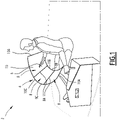
Figure 1 est une vue schématique en perspective d'un poste de pilotage individuel comprenant un système d'affichage électronique d'images ; - la
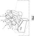
Figure 2 est une vue schématique en perspective d'un poste de pilotage pour deux pilotes, comprenant un système d'affichage électronique d'images ; - la
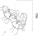
Figure 3 est une vue schématique en perspective d'un poste de pilotage pour deux pilotes, comprenant un système d'affichage électronique d'images avec plus d'écrans que dans lafigure 2 ; -
Figure 4 est une vue schématique de dessus d'une zone d'affichage d'un système d'affichage électronique d'images pour un poste de pilotage individuel ; et - la
Figure 5 est une vue schématique en section de la zone d'affichage, selon V-V sur laFigure 4 . - Le poste de pilotage 2 de la
Figure 1 est un poste de pilotage de véhicule, par exemple un poste de pilotage d'un aéronef. L'aéronef est par exemple un avion, un drone (i.e. un aéronef sans pilote humain à bord) ou un hélicoptère. - Dans une variante, le poste de pilotage est un poste de pilotage d'un véhicule ferroviaire, d'un véhicule maritime, par exemple un bâtiment de surface ou un sous-marin, ou d'un véhicule routier, par exemple une voiture ou un camion.
- Le poste de pilotage 2 est situé dans le véhicule ou hors du véhicule et configuré pour le pilotage du véhicule à distance, comme par exemple dans le cas du drone.
- Le poste de pilotage 2 comprend un système d'affichage électronique d'images 4 configuré pour l'affichage d'images. Le système d'affichage 4 est utilisable par exemple pour l'affichage de paramètres de pilotage du véhicule.
- Dans le cas d'un aéronef, le système d'affichage 4 est généralement configuré pour l'affichage de données telles que celles de pilotage, de navigation ou représentant l'état des systèmes (moteurs, hydraulique, électrique,...).
- Le système d'affichage 4 possède une surface d'affichage d'images 6 tridimensionnelle qui est définie par un seul écran d'affichage électronique d'images 8 ou plusieurs écrans d'affichage électronique d'images 8 jointifs.
- Chaque écran d'affichage 8 est configuré pour générer des images. Chaque écran d'affichage 8 comprend par exemple un ensemble de pixels répartis sur l'écran d'affichage 8 et configurés pour émettre de la lumière de manière à générer ensemble une image perceptible par un observateur.
- Dans un exemple de réalisation, chaque écran d'affichage 8 est par exemple électroluminescent, par exemple un écran à diodes électroluminescentes (ou LED pour « Light Emitting Diode » en anglais), en particulier un écran à diodes électroluminescentes organiques (ou OLED pour « Organic Light Emitting Diode » en anglais).
- Dans un exemple de réalisation, permettant notamment l'absence de bordure visible, chaque écran d'affichage 8 est un écran à micro-diodes électroluminescentes (ou écran micro-LED). De manière connue, les diodes électroluminescentes d'un écran micro-LED génère de la lumière à partir d'un matériau inorganique.
- Dans un autre exemple de réalisation chaque écran pourrait mettre en œuvre une technologie plus classique à cristaux liquides ou LCD pour « Liquid Crystai Display » en anglais.
- Dans un exemple de réalisation, chaque écran d'affichage 8 est dépourvu de bordure visible de telle sorte que l'ensemble de la surface d'affichage 6 parait continue pour l'utilisateur. De tels écrans d'affichage 8 dépourvus de bordure visible sont par exemple des écrans à Micro-LED.
- De préférence, la surface d'affichage 6 est au moins en partie tactile, et en particulier entièrement tactile. Pour ce faire au moins un ou chaque écran d'affichage 8 est tactile.
- Le caractère tactile de la surface d'affichage 6 permet à chaque pilote d'interagir avec le système d'affichage 4, soit pour configurer l'affichage des données sur la surface d'affichage 6, soit pour interagir avec et/ou commander des systèmes embarqués du véhicule, tels que des systèmes de mesure ou des systèmes de propulsions, des systèmes de guidage...
- La surface d'affichage 6 comprend au moins une zone d'affichage courbe 10 ayant la forme d'une surface développable, en particulier une portion de surface conique, encore plus en particulier une portion de surface conique de révolution.
- Chaque zone d'affichage courbe 10 est tridimensionnelle. Chaque zone d'affichage courbe 10 est non-plane. Chaque zone d'affichage courbe 10 est de préférence dépourvue de cassure ou d'arête.
- Une surface développable est par définition une surface réglée, i.e. formée d'une infinité de droites génératrices, dont toute droite génératrice est stationnaire, c'est-à-dire telle que le plan tangent à la surface développable est le même en tout point de la droite génératrice
- Une surface conique (ou cône) est par définition une surface réglée générée par des droites génératrices passant par un point fixe appelé sommet et un point variable décrivant une courbe appelée courbe directrice.
- Une surface conique désigne ici une surface non-cylindrique. Une surface cylindrique n'est pas considérée ici comme une surface conique.
- Dans la suite de la description, par souci de concision, sauf indication contraire, l'expression « zone d'affichage courbe » désigne une zone d'affichage courbe ayant la forme d'une surface développable, et en particulier d'une portion de surface conique.
- Par ailleurs, l'expression « droite génératrice » désigne une droite génératrice de la surface développable, et en particulier dans le cas d'une surface conique, une droite génératrice passant par le sommet de la surface conique et par la courbe directrice de la surface conique.
- Une surface conique de révolution (ou « surface conique circulaire droite ») est une surface conique possédant un sommet situé sur un axe de révolution et une courbe directrice circulaire située dans un plan perpendiculaire à l'axe de révolution et dont le centre est situé sur l'axe de révolution. Dans un exemple de réalisation, au moins une ou chaque zone d'affichage courbe 10 a la forme d'une portion de surface conique de révolution, délimitée entre deux plans parallèles perpendiculaire à l'axe de révolution de la surface conique de révolution, et deux droites directrices de la surface conique de révolution.
- Une telle zone d'affichage courbe 10 correspond à une fraction de la surface latérale d'un tronc de cône de révolution.
- Une telle zone d'affichage courbe 10 est délimitée par deux bords rectilignes 10A opposés et deux bords curvilignes 10B, 10C opposés.
- Les deux bords rectilignes 10A correspondant à deux droites directrices de la surface tronconique de révolution,
- Les deux bords curvilignes 10B, 10C sont des arcs de cercles de rayons différents et de longueurs différentes. Les deux bords curvilignes 10B, 10C sont centrés sur l'axe de révolution de la surface conique de révolution.
- Lorsque la zone d'affichage courbe 10 est concave, comme c'est le cas sur la
Figure 1 , de préférence, le bord curviligne 10B court et le bord curviligne 10C long définissent respectivement le bord inférieur et le bord supérieur de la zone d'affichage courbe 10. - Lorsque la zone d'affichage courbe 10 est convexe, de préférence, le bord curviligne court et le bord curviligne long définissent respectivement le bord supérieur et le bord inférieur de la zone d'affichage courbe 10.
- Chaque zone d'affichage courbe 10 de la surface d'affichage est de préférence orientée vers le haut. Ainsi, le pilote assis à son poste de pilotage peut regarder la zone d'affichage 10 en regardant obliquement vers le bas.
- L'axe de révolution de la surface conique de révolution, dont la zone d'affichage courbe 10 forme une portion, est de préférence sensiblement vertical.
- Chaque écran d'affichage 8 définissant une zone d'affichage courbe 10 est lui-même courbe et a la forme d'une surface développable, et en particulier une portion de surface conique, et encore plus en particulier la forme d'une portion de surface conique de révolution.
- Dans un exemple de réalisation particulier, au moins un ou chaque écran d'affichage 8 a la forme d'une portion de surface conique de révolution délimité entre deux plans parallèles perpendiculaire à l'axe de révolution de la surface tronconique de révolution, et deux droites directrices de la surface conique de révolution.
- Chaque écran d'affichage 8 de ce type correspond à une fraction de la surface latérale d'un tronc de cône de révolution ;
- Chaque écran d'affichage 8 de ce type est délimité par deux bords rectilignes 8A opposés correspondant à deux droites directrices de la surface conique de révolution, et deux bords curvilignes 8B, 8C opposés.
- Les deux bords curvilignes 8B, 8C opposés sont des arcs de cercles de rayons différents et de longueurs différentes. Les deux bords curvilignes 8B, 8C sont centrés sur l'axe de révolution de la surface tronconique de révolution.
- Dans l'exemple de réalisation illustré sur la
Figure 1 , la zone d'affichage courbe 10 de la surface d'affichage 6 est formée de trois écrans d'affichage 8 qui sont chacun une portion de surface conique de révolution, disposés côte à côte et jointifs par leurs bords rectilignes 8A respectifs. - Les bords curvilignes 8B courts des écrans d'affichage 8 se prolongent pour former le bord curviligne 10B court de la zone d'affichage courbe 10, et les bords curvilignes 8C longs des écrans d'affichage 8 se prolongent pour former le bord curviligne 10C long de la zone d'affichage courbe 10.
- La zone d'affichage courbe 10 est plus étendue angulairement autour de l'axe de révolution de la surface conique de révolution dont la zone d'affichage courbe 10 est une portion, que chacun des écrans d'affichage 8 formant la zone d'affichage courbe 10.
- Avantageusement, au moins deux écrans d'affichage 8 formant une même zone d'affichage courbe 10, et en particulier, comme illustré sur la
Figure 1 , tous les écrans d'affichage 8 formant une même zone d'affichage courbe 10, sont identiques. - Ceci permet de construire la zone d'affichage courbe 10 qui est une développable, et en particulier une portion de surface conique, de façon modulaire à partir d'écrans d'affichage 8 identiques, en adaptant le nombre d'écrans d'affichage 8 en fonction de l'étendue souhaitée pour la zone d'affichage courbe 10 qui est une surface développable, et en particulier une portion de surface conique.
- Les écrans d'affichages 8 sont ici au nombre de trois, mais bien entendu, dans des variantes possibles, une zone d'affichage courbe est formée d'un écran d'affichage, de deux écrans d'affichage jointifs ou de plus de trois écrans d'affichage jointifs. Le nombre exact d'écrans dépend, entre autres, des exigences de disponibilité de l'information en cas de panne d'un des écrans ou de l'espace disponible dans le cockpit.
- Dans l'exemple de réalisation de la
Figure 1 , la surface d'affichage 6 comprend une seule zone d'affichage courbe 10 qui est concave. - Le poste de pilotage de la
Figure 2 diffère de celui de laFigure 1 en ce que la surface d'affichage 8 possède plusieurs zones d'affichage courbes 10, 12 distinctes, incluant ici une zone d'affichage courbe 12 convexe, située entre deux zones d'affichage courbes 10 concaves. - Le poste de pilotage de la
Figure 2 est par exemple prévu pour deux pilotes assis côte à côte. - Chaque zone d'affichage courbe 10 concave définit une zone d'affichage dédiée à un pilote et située devant ce pilote, et la zone d'affichage courbe 12 convexe définit une zone d'affichage située entre les pilotes et partagée par les pilotes.
- Dans l'exemple de réalisation de la
Figure 2 , chaque zone d'affichage courbe 10, 12 a la forme d'une surface développable, en particulier une portion de surface conique, plus particulièrement ici une portion de surface conique de révolution, délimitée entre deux plans perpendiculaires à l'axe de révolution de la surface conique de révolution, et entre deux droites génératrices de la surface tronconique de révolution. - Chaque zone d'affichage courbe 10, 12 est ici formée par un seul écran 8, 14 d'affichage ayant une forme coïncidant avec celle de la zone d'affichage courbe 10, 12 correspondante.
- Avantageusement, lorsque la surface d'affichage 6 comprend une zone d'affichage courbe 10 concave et une zone d'affichage courbe 12 convexe adjacentes, celles-ci sont formées respectivement par un écran d'affichage 8 concave et un écran d'affichage 14 convexe jointifs par des bords rectilignes 8A, 14A respectifs.
- L'écran d'affichage 8 concave et l'écran d'affichage 14 ont chacun la forme d'une surface développable, en particulier une portion de surface conique, plus particulièrement ici une portion de surface conique de révolution.
- De préférence, l'écran d'affichage 8 concave et l'écran d'affichage 14 ont chacun la forme d'une portion de surface tronconique de révolution délimitée entre deux plans parallèles perpendiculaire à l'axe de révolution de la surface conique de révolution, et deux droites directrices distinctes de la surface conique de révolution.
- Dans un exemple de réalisation préféré, l'écran d'affichage 8 concave et l'écran d'affichage 14 convexe ont des bords rectilignes 8A, 14A de même longueur. Ceci permet de disposer les écrans d'affichage 8, 14 par leurs bords rectilignes 8A, 14A de manière qu'ils se prolongent l'un l'autre.
- En option, l'écran d'affichage 8 concave et l'écran d'affichage 14 convexe ont des bords curvilignes courts de même rayon de courbure et des bords curviligne longs de même rayon de courbure.
- Dans ce cas les écrans 8 et 14 sont par exemple issus d'une même forme plane courbée sur une surface concave pour l'écran 8 et pivotée de 180° puis courbée sur une surface convexe pour l'écran 14. Les coûts de développement sont ainsi minimisés en utilisant la même forme de départ.
- L'écran d'affichage 14 convexe est disposé de façon que son bord curviligne 14B long définit un bord inférieur de la zone d'affichage courbe 12 convexe et que son bord curviligne 14C court définit un bord supérieur de la zone d'affichage courbe 12 convexe.
- D'une manière générale, on pourrait avoir des écrans d'affichage 8, 14 concaves et convexes avec des bords longs de rayons de courbure différents et/ou des bords courts de rayons de courbure différents, avec par exemple des matrices de pixels différentes entre écrans concaves et convexes.
- De préférence, l'écran d'affichage 14 convexe est disposé tête-bêche par rapport à chaque écran d'affichage 8 concave avec lequel il est jointif.
- Avantageusement, le bord curviligne 14B long de l'écran d'affichage convexe prolonge le bord curviligne 8B court de chaque écran d'affichage 8 concave jointif et/ou le bord curviligne court 14C de l'écran d'affichage 14 convexe prolonge le bord curviligne 8C long de chaque écran d'affichage 8 concave jointif.
- L'utilisation de tels écrans d'affichage 8, 14 concave et convexe disposés tête-bêche permet de former une surface d'affichage courbe ayant la forme d'une bande ondulante avec une alternance de zones d'affichage 10, 12 concave et convexe. Une telle bande est particulièrement ergonomique pour la réalisation d'un poste de pilotage pour deux pilotes. Dans l'exemple de réalisation de la
Figure 2 , chaque zone d'affichage courbe 10, 12 est formée d'un seul écran d'affichage. En variante, au moins une zone d'affichage courbe 10, 12 est formée de plusieurs écrans d'affichage jointifs. - Le poste de pilotage de la
Figure 3 diffère de celui de laFigure 2 en ce que chaque zone d'affichage courbe 10 concave est formée de deux écrans d'affichage 8 jointifs disposés côte à côte. - Dans l'exemple illustré, les deux écrans d'affichage 8 formant chaque zone d'affichage courbe 10 sont différents, l'un étant plus large que l'autre.
- Dans une variante possible, une seule zone d'affichage courbe 10 concave est formée de plusieurs écrans d'affichage 8 jointifs disposés côte à côte, l'autre zone d'affichage courbe 10 concave étant formée d'un seul écran d'affichage 8.
- Par ailleurs, en option ou en variante, la surface d'affichage comprend au moins une zone d'affichage courbe 12 convexe formée de plusieurs écrans d'affichage 8 jointifs.
- De manière générale, la surface d'affichage 6 comprend au moins une zone d'affichage courbe 10 concave formée d'un seul écran d'affichage 8, au moins une zone d'affichage courbe 10 concave formée de plusieurs écrans d'affichage 8, jointifs, au moins une zone d'affichage courbe 12 convexe formée de plusieurs écrans d'affichage 14 jointifs, et/ou au moins une zone d'affichage courbe 12 convexe formée d'un seul écran d'affichage 14.
- La
Figure 4 illustre une vue de dessus d'une zone d'affichage courbe 10 concave dédiée à un pilote, et la Figue 5 illustre la zone d'affichage en section selon V-V sur laFigure 4 . - La zone d'affichage courbe 10 concave est une portion de surface tronconique de révolution ayant un axe de révolution A, située entre deux plans parallèles P1, P2 (
Figure 5 ) distincts perpendiculaire à l'axe de révolution A, et deux segments de droites génératrices D1, D2 de la surface conique de révolution (Figure 4 ). Les segments de droites génératrices D1, D2 correspondent aux bords latéraux 10A de la zone d'affichage courbe 10. - Sur les
Figures 4 et5 , le point de vision DE représente la position d'un point de vision théorique d'un pilote assis devant la zone d'affichage, pour la conception de la zone d'affichage. - L'axe de révolution A de la surface conique est sensiblement vertical (
Figure 4 ). Par ailleurs, en section dans un plan vertical (Figure 5 ), la zone d'affichage courbe conique s'étend obliquement en étant tournée vers le haut. - De préférence, en vue de dessus, le point de vision DE est situé entre l'axe de révolution A et le point du bord inférieur de la zone d'affichage situé devant le pilote.
- Ainsi, la distance d entre le point de vision DE et le point du bord inférieur de la zone d'affichage situé devant le pilote est inférieure au rayon de courbure R du bord inférieur 10B.
- De préférence, le rayon de courbure du bord interne est choisi de telle manière qu'une distance d entre le point de vision DE et le point du bord inférieur de la zone d'affichage situé devant le pilote est strictement inférieure à une distance D entre le point de vision DE et chaque extrémité du bord inférieur 10B de la zone d'affichage courbe 10.
- Des valeurs typiques sont une distance d comprise entre 400 et 450 mm, par exemple environ 430 mm, et une distance D comprise entre 550 et 600 mm, par exemple environ 580.
- Par ailleurs, de préférence, le demi-angle au sommet α (
Figure 5 ) de la surface conique de révolution associée à chaque zone d'affichage courbe conique ayant la forme d'une portion de surface conique de révolution est compris entre 30 et 55°. - Le demi-angle au sommet de la surface conique de révolution est l'angle défini à l'intérieur de la surface conique de révolution entre l'axe de révolution A de la surface conique de révolution et une droite directrice de la surface conique de révolution.
- La plage angulaire spécifiée permet d'obtenir une zone d'affichage courbe ayant une ergonomie satisfaisante, en terme de visibilité des images pour le pilote et d'accessibilité, par exemple lorsque la zone d'affichage courbe est au moins en partie tactile pour permettre au pilote d'interagir avec le système d'affichage.
- La réalisation d'une surface d'affichage d'image formée d'un écran d'affichage ou plusieurs écrans d'affichage jointifs permet de proposer une surface d'affichage étendue. Ceci permet d'augmenter le nombre d'informations affichées simultanément, et d'améliorer le partage d'information entre pilotes.
- La prévision d'une zone d'affichage courbe ayant la forme d'une surface développable, en particulier une portion de surface conique, encore plus en particulier d'une telle zone d'affichage pour chaque pilote, permet d'obtenir une ergonomie satisfaisante.
- La zone d'affichage courbe permet de conformer la surface d'affichage à l'enveloppe d'accessibilité de chaque pilote pour une interaction plus facile.
- Cela permet de réduire les efforts musculaires pour les pilotes pour interagir avec la surface d'affichage lorsque celle-ci est au moins partiellement tactile, et améliore la stabilité des doigts des pilotes, ce qui permet une utilisation plus précise et plus facile.
- La réalisation de la surface d'affichage avec plusieurs écrans d'affichage jointifs permet de maximiser la surface d'affichage et d'afficher des formats à cheval sur plusieurs écrans. Elle facilite également l'échange d'information entre les pilotes, par exemple en leur permettant de déplacer une image générée sur la surface d'affichage d'un pilote vers l'autre pour partager une information contenue dans cette image.
- La réalisation de la surface d'affichage avec plusieurs écrans d'affichage jointifs fournit également un gain de sécurité en permettant au système d'affichage de continuer à fonctionner dans un mode dégradé, y compris lorsqu'un des écrans d'affichage est défaillant. En particulier, au moins une ou chaque zone d'affichage peut être réalisée à l'aide de plusieurs écrans d'affichage jointifs.
- Pour la réalisation des systèmes d'affichage décrit, un écran d'affichage ayant la forme d'une portion de surface conique, notamment d'une portion de surface conique de révolution, est par exemple formé en fournissant un écran d'affichage flexible en forme de secteur angulaire de couronne circulaire, et en fixant cet écran flexible sur une surface de support rigide qui est une portion de surface tronconique de révolution.
- Un écran d'affichage flexible est par exemple un écran à OLEDs, un écran à Micro-LED, un écran LCD sur verre aminci ou un écran LCD sur plastique.
- En variante, un tel écran d'affichage est formé en fixant des éléments générateurs de lumière tels que des LEDs, des OLEDs ou des Micro-LED sur une surface de support qui est une portion de surface tronconique de révolution.
- L'invention n'est pas limitée aux exemples de réalisation décrit, des variantes étant envisageables.
- Par exemple, les systèmes d'affichage des exemples de réalisation des
Figures 1 à 3 possèdent plusieurs écrans d'affichage distincts qui sont disposés jointifs pour former une surface d'affichage plus étendue que chaque écran d'affichage. - Dans une variante, la surface d'affichage est formée par un seul écran d'affichage courbe définissant une zone d'affichage courbe ayant la forme d'une surface développable, en particulier conique, ou plusieurs zones d'affichages courbes ayant la forme de surfaces développables, en particulier coniques.
- Par ailleurs, dans les modes de réalisation décrits, les surfaces d'affichage comprennent exclusivement des zones d'affichages courbes ayant la forme d'une surface développable, en particulier une portion de surface conique.
- Dans des variantes, il est envisageable qu'une surface d'affichage possède au moins une zone d'affichage non-courbe et/ou une zone d'affichage courbe mais non-développable ou non-conique, par exemple au moins une zone d'affichage plane et/ou au moins une zone d'affichage courbe ayant la forme d'une portion de surface cylindrique.
Claims (11)
- Système d'affichage électronique d'images pour poste de pilotage de véhicule, le système d'affichage possédant une surface d'affichage (6) tridimensionnelle non-plane définie par un écran d'affichage (8) électronique ou plusieurs écrans d'affichage (8, 14) électroniques jointifs, la surface d'affichage (6) ayant au moins une zone d'affichage courbe (10, 12) ayant la forme d'une surface développable, dans lequel au moins une ou chaque zone d'affichage courbe (10, 12) ayant la forme d'une surface développable a la forme d'une portion de surface conique.
- Système d'affichage selon la revendication 1, dans lequel chaque zone d'affichage courbe (10, 12) de la surface d'affichage (6) est une zone d'affichage courbe ayant la forme d'une surface développable.
- Système d'affichage selon la revendication 1 ou la revendication 2, dans lequel au moins une zone d'affichage courbe (10, 12) ayant la forme d'une surface développable est définie par un seul écran d'affichage (8) et/ou au moins une zone d'affichage courbe ayant la forme d'une surface développable est définie par plusieurs écrans (8 ; 14) d'affichage jointifs.
- Système d'affichage selon l'une quelconque des revendications précédentes, dans lequel la surface d'affichage (6) est constituée de plusieurs zones d'affichage courbes (10, 12) ayant chacune la forme d'une surface développable.
- Système d'affichage selon l'une quelconque des revendications précédentes, dans lequel au moins une ou chaque zone d'affichage courbe (10, 12) ayant la forme d'une surface développable a la forme d'une portion de surface conique de révolution.
- Système d'affichage selon l'une quelconque des revendications précédentes, dans lequel chaque écran d'affichage (8, 14) définissant, en totalité ou en partie, une zone d'affichage courbe (10, 12) ayant la forme d'une surface développable a la forme d'une portion de surface conique, en particulier d'une portion de surface conique de révolution.
- Système d'affichage selon l'une quelconque des revendications précédentes, dans lequel au moins un écran d'affichage (8, 14) a la forme d'une portion de surface conique de révolution, délimitée entre deux plans parallèles perpendiculaire à l'axe de révolution de la surface conique de révolution, et deux plans axiaux distincts incluant l'axe de révolution en faisant un angle non nul entre eux.
- Système d'affichage selon l'une quelconque des revendications précédentes, dans lequel la surface d'affichage (6) est constituée d'un ou plusieurs écrans d'affichage (8, 14) ayant chacun la forme d'une portion de surface tronconique de révolution, délimitée entre deux plans parallèles perpendiculaire à l'axe de révolution de la surface tronconique de révolution, et deux plans axiaux distincts incluant l'axe de révolution en faisant un angle non nul entre eux.
- Système d'affichage selon l'une quelconque des revendications précédentes, dans lequel au moins une zone d'affichage courbe (10) est concave et/ou au moins une zone d'affichage courbe (12) est convexe.
- Système d'affichage selon l'une quelconque des revendications précédentes, dans lequel la surface d'affichage comprend trois zones d'affichage courbes (10, 12) adjacentes incluant une zone d'affichage courbe (12) convexe située entre deux zones d'affichage courbes (10) concaves.
- Poste de pilotage de véhicule, par exemple d'aéronef, comprenant un système d'affichage électronique selon l'une quelconque des revendications précédentes.
Applications Claiming Priority (1)
| Application Number | Priority Date | Filing Date | Title |
|---|---|---|---|
| FR1871754A FR3088864B1 (fr) | 2018-11-23 | 2018-11-23 | Système d’affichage électronique d’images pour poste de pilotage de véhicule possédant une zone d’affichage de forme développable |
Publications (2)
| Publication Number | Publication Date |
|---|---|
| EP3656598A1 EP3656598A1 (fr) | 2020-05-27 |
| EP3656598B1 true EP3656598B1 (fr) | 2022-12-07 |
Family
ID=66641017
Family Applications (1)
| Application Number | Title | Priority Date | Filing Date |
|---|---|---|---|
| EP19210749.8A Active EP3656598B1 (fr) | 2018-11-23 | 2019-11-21 | Système d'affichage électronique d'images pour poste de pilotage de véhicule possédant une zone d'affichage de forme développable |
Country Status (4)
| Country | Link |
|---|---|
| US (1) | US20200167117A1 (fr) |
| EP (1) | EP3656598B1 (fr) |
| CN (1) | CN111223410A (fr) |
| FR (1) | FR3088864B1 (fr) |
Families Citing this family (3)
| Publication number | Priority date | Publication date | Assignee | Title |
|---|---|---|---|---|
| US20200307823A1 (en) * | 2019-03-29 | 2020-10-01 | Honeywell International Inc. | Intelligent and ergonomic flight deck workstation |
| IT202100029162A1 (it) * | 2021-11-18 | 2023-05-18 | Ferrari Spa | Dispositivo di visualizzazione per cruscotto di un veicolo stradale e relativo veicolo stradale |
| US20250115357A1 (en) * | 2023-10-10 | 2025-04-10 | Panasonic Avionics Corporation | Curved seatback monitors and associated systems, devices, and methods |
Family Cites Families (5)
| Publication number | Priority date | Publication date | Assignee | Title |
|---|---|---|---|---|
| US4794742A (en) * | 1986-03-19 | 1989-01-03 | Henderson Charles E | Multi-conic shell and method of forming same |
| US5083389A (en) * | 1988-07-15 | 1992-01-28 | Arthur Alperin | Panoramic display device and method of making the same |
| FR3000026B1 (fr) * | 2012-12-21 | 2016-12-09 | Airbus | Aeronef comprenant un poste de pilotage dote d'une surface de vision pour le pilotage au moins partiellement virtuelle |
| DE102015009141A1 (de) * | 2015-07-14 | 2017-01-19 | Audi Ag | Anzeigeeinrichtung |
| US10930205B2 (en) * | 2016-05-19 | 2021-02-23 | Semiconductor Energy Laboratory Co., Ltd. | Display system and moving object |
-
2018
- 2018-11-23 FR FR1871754A patent/FR3088864B1/fr not_active Expired - Fee Related
-
2019
- 2019-11-21 EP EP19210749.8A patent/EP3656598B1/fr active Active
- 2019-11-21 US US16/691,220 patent/US20200167117A1/en not_active Abandoned
- 2019-11-22 CN CN201911155253.5A patent/CN111223410A/zh active Pending
Also Published As
| Publication number | Publication date |
|---|---|
| CN111223410A (zh) | 2020-06-02 |
| EP3656598A1 (fr) | 2020-05-27 |
| US20200167117A1 (en) | 2020-05-28 |
| FR3088864B1 (fr) | 2021-08-27 |
| FR3088864A1 (fr) | 2020-05-29 |
Similar Documents
| Publication | Publication Date | Title |
|---|---|---|
| EP3656598B1 (fr) | Système d'affichage électronique d'images pour poste de pilotage de véhicule possédant une zone d'affichage de forme développable | |
| EP3656597B1 (fr) | Système d'affichage électronique d'images pour poste de pilotage de véhicule avec surface d'affichage tridimensionnelle | |
| FR3000026A1 (fr) | Aeronef comprenant un poste de pilotage dote d'une surface de vision pour le pilotage au moins partiellement virtuelle | |
| EP2703295B1 (fr) | Ecran de visualisation transparent double-face | |
| FR3000027A1 (fr) | Poste de pilotage d'aeronef a tableau de bord ergonomique reglable | |
| EP3507543B1 (fr) | Dispositif d'eclairage medical avec des leds orientees par des languettes predecoupees dans une carte de circuit imprime | |
| EP2647572A1 (fr) | Système de visualisations modulaire pour hélicoptère | |
| EP3856570B1 (fr) | Système optique pour éclairage intérieur d'un véhicule | |
| FR2991295A1 (fr) | Aeronef a grande visibilite | |
| FR2996927A1 (fr) | Poste de pilotage avec dispositif de visualisation tete haute, notamment pour un aeronef | |
| FR3000025A1 (fr) | Aeronef comprenant un poste de pilotage delocalise en dehors d'une partie superieure de la pointe avant | |
| FR3067993A1 (fr) | Habillage interieur de vehicule comprenant un dispositif d'affichage | |
| US7086764B2 (en) | Glare resistant displays for automotive vehicles and lenses for such displays | |
| EP3521765B1 (fr) | Procédé de visualisation de l'attitude d'un aéronef, produit programme d'ordinateur et système de visualisation associés | |
| EP2788217A1 (fr) | Interface homme-machine pour véhicule automobile | |
| EP2665617B1 (fr) | Tableau de bord et methode d'assemblage d'un tableau de bord | |
| US20130215594A1 (en) | Illuminating structure of meter apparatus | |
| EP3629074B1 (fr) | Système d'affichage tête haute, procédé d'affichage et produit programme d'ordinateur associés | |
| EP2463155A2 (fr) | Dispositif de rétroéclairage amélioré | |
| WO2007065806A1 (fr) | Procede de synthese d'images d'intervisibilite | |
| EP2745162B1 (fr) | Dispositif d'affichage, notamment pour véhicule automobile | |
| WO2021099738A1 (fr) | Véhicule pilotable à distance avec affichage amélioré | |
| JP6446679B2 (ja) | 車両用計器装置 | |
| FR3146628A1 (fr) | Elément de garnissage comprenant une zone d’affichage réfléchissant la lumière d’un dispositif d’affichage | |
| FR3008195A1 (fr) | Viseur tete-haute |
Legal Events
| Date | Code | Title | Description |
|---|---|---|---|
| PUAI | Public reference made under article 153(3) epc to a published international application that has entered the european phase |
Free format text: ORIGINAL CODE: 0009012 |
|
| STAA | Information on the status of an ep patent application or granted ep patent |
Free format text: STATUS: THE APPLICATION HAS BEEN PUBLISHED |
|
| AK | Designated contracting states |
Kind code of ref document: A1 Designated state(s): AL AT BE BG CH CY CZ DE DK EE ES FI FR GB GR HR HU IE IS IT LI LT LU LV MC MK MT NL NO PL PT RO RS SE SI SK SM TR |
|
| AX | Request for extension of the european patent |
Extension state: BA ME |
|
| STAA | Information on the status of an ep patent application or granted ep patent |
Free format text: STATUS: REQUEST FOR EXAMINATION WAS MADE |
|
| 17P | Request for examination filed |
Effective date: 20201027 |
|
| RBV | Designated contracting states (corrected) |
Designated state(s): AL AT BE BG CH CY CZ DE DK EE ES FI FR GB GR HR HU IE IS IT LI LT LU LV MC MK MT NL NO PL PT RO RS SE SI SK SM TR |
|
| GRAP | Despatch of communication of intention to grant a patent |
Free format text: ORIGINAL CODE: EPIDOSNIGR1 |
|
| STAA | Information on the status of an ep patent application or granted ep patent |
Free format text: STATUS: GRANT OF PATENT IS INTENDED |
|
| INTG | Intention to grant announced |
Effective date: 20220928 |
|
| GRAS | Grant fee paid |
Free format text: ORIGINAL CODE: EPIDOSNIGR3 |
|
| GRAA | (expected) grant |
Free format text: ORIGINAL CODE: 0009210 |
|
| STAA | Information on the status of an ep patent application or granted ep patent |
Free format text: STATUS: THE PATENT HAS BEEN GRANTED |
|
| AK | Designated contracting states |
Kind code of ref document: B1 Designated state(s): AL AT BE BG CH CY CZ DE DK EE ES FI FR GB GR HR HU IE IS IT LI LT LU LV MC MK MT NL NO PL PT RO RS SE SI SK SM TR |
|
| REG | Reference to a national code |
Ref country code: GB Ref legal event code: FG4D Free format text: NOT ENGLISH |
|
| REG | Reference to a national code |
Ref country code: CH Ref legal event code: EP Ref country code: AT Ref legal event code: REF Ref document number: 1536107 Country of ref document: AT Kind code of ref document: T Effective date: 20221215 |
|
| REG | Reference to a national code |
Ref country code: DE Ref legal event code: R096 Ref document number: 602019022829 Country of ref document: DE |
|
| REG | Reference to a national code |
Ref country code: IE Ref legal event code: FG4D Free format text: LANGUAGE OF EP DOCUMENT: FRENCH |
|
| REG | Reference to a national code |
Ref country code: LT Ref legal event code: MG9D |
|
| REG | Reference to a national code |
Ref country code: NL Ref legal event code: MP Effective date: 20221207 |
|
| PG25 | Lapsed in a contracting state [announced via postgrant information from national office to epo] |
Ref country code: SE Free format text: LAPSE BECAUSE OF FAILURE TO SUBMIT A TRANSLATION OF THE DESCRIPTION OR TO PAY THE FEE WITHIN THE PRESCRIBED TIME-LIMIT Effective date: 20221207 Ref country code: NO Free format text: LAPSE BECAUSE OF FAILURE TO SUBMIT A TRANSLATION OF THE DESCRIPTION OR TO PAY THE FEE WITHIN THE PRESCRIBED TIME-LIMIT Effective date: 20230307 Ref country code: LT Free format text: LAPSE BECAUSE OF FAILURE TO SUBMIT A TRANSLATION OF THE DESCRIPTION OR TO PAY THE FEE WITHIN THE PRESCRIBED TIME-LIMIT Effective date: 20221207 Ref country code: FI Free format text: LAPSE BECAUSE OF FAILURE TO SUBMIT A TRANSLATION OF THE DESCRIPTION OR TO PAY THE FEE WITHIN THE PRESCRIBED TIME-LIMIT Effective date: 20221207 Ref country code: ES Free format text: LAPSE BECAUSE OF FAILURE TO SUBMIT A TRANSLATION OF THE DESCRIPTION OR TO PAY THE FEE WITHIN THE PRESCRIBED TIME-LIMIT Effective date: 20221207 |
|
| REG | Reference to a national code |
Ref country code: AT Ref legal event code: MK05 Ref document number: 1536107 Country of ref document: AT Kind code of ref document: T Effective date: 20221207 |
|
| PG25 | Lapsed in a contracting state [announced via postgrant information from national office to epo] |
Ref country code: RS Free format text: LAPSE BECAUSE OF FAILURE TO SUBMIT A TRANSLATION OF THE DESCRIPTION OR TO PAY THE FEE WITHIN THE PRESCRIBED TIME-LIMIT Effective date: 20221207 Ref country code: PL Free format text: LAPSE BECAUSE OF FAILURE TO SUBMIT A TRANSLATION OF THE DESCRIPTION OR TO PAY THE FEE WITHIN THE PRESCRIBED TIME-LIMIT Effective date: 20221207 Ref country code: LV Free format text: LAPSE BECAUSE OF FAILURE TO SUBMIT A TRANSLATION OF THE DESCRIPTION OR TO PAY THE FEE WITHIN THE PRESCRIBED TIME-LIMIT Effective date: 20221207 Ref country code: HR Free format text: LAPSE BECAUSE OF FAILURE TO SUBMIT A TRANSLATION OF THE DESCRIPTION OR TO PAY THE FEE WITHIN THE PRESCRIBED TIME-LIMIT Effective date: 20221207 Ref country code: GR Free format text: LAPSE BECAUSE OF FAILURE TO SUBMIT A TRANSLATION OF THE DESCRIPTION OR TO PAY THE FEE WITHIN THE PRESCRIBED TIME-LIMIT Effective date: 20230308 |
|
| P01 | Opt-out of the competence of the unified patent court (upc) registered |
Effective date: 20230425 |
|
| PG25 | Lapsed in a contracting state [announced via postgrant information from national office to epo] |
Ref country code: NL Free format text: LAPSE BECAUSE OF FAILURE TO SUBMIT A TRANSLATION OF THE DESCRIPTION OR TO PAY THE FEE WITHIN THE PRESCRIBED TIME-LIMIT Effective date: 20221207 |
|
| PG25 | Lapsed in a contracting state [announced via postgrant information from national office to epo] |
Ref country code: SM Free format text: LAPSE BECAUSE OF FAILURE TO SUBMIT A TRANSLATION OF THE DESCRIPTION OR TO PAY THE FEE WITHIN THE PRESCRIBED TIME-LIMIT Effective date: 20221207 Ref country code: RO Free format text: LAPSE BECAUSE OF FAILURE TO SUBMIT A TRANSLATION OF THE DESCRIPTION OR TO PAY THE FEE WITHIN THE PRESCRIBED TIME-LIMIT Effective date: 20221207 Ref country code: PT Free format text: LAPSE BECAUSE OF FAILURE TO SUBMIT A TRANSLATION OF THE DESCRIPTION OR TO PAY THE FEE WITHIN THE PRESCRIBED TIME-LIMIT Effective date: 20230410 Ref country code: EE Free format text: LAPSE BECAUSE OF FAILURE TO SUBMIT A TRANSLATION OF THE DESCRIPTION OR TO PAY THE FEE WITHIN THE PRESCRIBED TIME-LIMIT Effective date: 20221207 Ref country code: CZ Free format text: LAPSE BECAUSE OF FAILURE TO SUBMIT A TRANSLATION OF THE DESCRIPTION OR TO PAY THE FEE WITHIN THE PRESCRIBED TIME-LIMIT Effective date: 20221207 Ref country code: AT Free format text: LAPSE BECAUSE OF FAILURE TO SUBMIT A TRANSLATION OF THE DESCRIPTION OR TO PAY THE FEE WITHIN THE PRESCRIBED TIME-LIMIT Effective date: 20221207 |
|
| PG25 | Lapsed in a contracting state [announced via postgrant information from national office to epo] |
Ref country code: SK Free format text: LAPSE BECAUSE OF FAILURE TO SUBMIT A TRANSLATION OF THE DESCRIPTION OR TO PAY THE FEE WITHIN THE PRESCRIBED TIME-LIMIT Effective date: 20221207 Ref country code: IS Free format text: LAPSE BECAUSE OF FAILURE TO SUBMIT A TRANSLATION OF THE DESCRIPTION OR TO PAY THE FEE WITHIN THE PRESCRIBED TIME-LIMIT Effective date: 20230407 Ref country code: AL Free format text: LAPSE BECAUSE OF FAILURE TO SUBMIT A TRANSLATION OF THE DESCRIPTION OR TO PAY THE FEE WITHIN THE PRESCRIBED TIME-LIMIT Effective date: 20221207 |
|
| REG | Reference to a national code |
Ref country code: DE Ref legal event code: R097 Ref document number: 602019022829 Country of ref document: DE |
|
| PLBE | No opposition filed within time limit |
Free format text: ORIGINAL CODE: 0009261 |
|
| STAA | Information on the status of an ep patent application or granted ep patent |
Free format text: STATUS: NO OPPOSITION FILED WITHIN TIME LIMIT |
|
| PG25 | Lapsed in a contracting state [announced via postgrant information from national office to epo] |
Ref country code: DK Free format text: LAPSE BECAUSE OF FAILURE TO SUBMIT A TRANSLATION OF THE DESCRIPTION OR TO PAY THE FEE WITHIN THE PRESCRIBED TIME-LIMIT Effective date: 20221207 |
|
| 26N | No opposition filed |
Effective date: 20230908 |
|
| PG25 | Lapsed in a contracting state [announced via postgrant information from national office to epo] |
Ref country code: SI Free format text: LAPSE BECAUSE OF FAILURE TO SUBMIT A TRANSLATION OF THE DESCRIPTION OR TO PAY THE FEE WITHIN THE PRESCRIBED TIME-LIMIT Effective date: 20221207 |
|
| PG25 | Lapsed in a contracting state [announced via postgrant information from national office to epo] |
Ref country code: IT Free format text: LAPSE BECAUSE OF FAILURE TO SUBMIT A TRANSLATION OF THE DESCRIPTION OR TO PAY THE FEE WITHIN THE PRESCRIBED TIME-LIMIT Effective date: 20221207 |
|
| REG | Reference to a national code |
Ref country code: CH Ref legal event code: PL |
|
| PG25 | Lapsed in a contracting state [announced via postgrant information from national office to epo] |
Ref country code: MC Free format text: LAPSE BECAUSE OF FAILURE TO SUBMIT A TRANSLATION OF THE DESCRIPTION OR TO PAY THE FEE WITHIN THE PRESCRIBED TIME-LIMIT Effective date: 20221207 |
|
| PG25 | Lapsed in a contracting state [announced via postgrant information from national office to epo] |
Ref country code: LU Free format text: LAPSE BECAUSE OF NON-PAYMENT OF DUE FEES Effective date: 20231121 |
|
| PG25 | Lapsed in a contracting state [announced via postgrant information from national office to epo] |
Ref country code: CH Free format text: LAPSE BECAUSE OF NON-PAYMENT OF DUE FEES Effective date: 20231130 |
|
| GBPC | Gb: european patent ceased through non-payment of renewal fee |
Effective date: 20231121 |
|
| PG25 | Lapsed in a contracting state [announced via postgrant information from national office to epo] |
Ref country code: MC Free format text: LAPSE BECAUSE OF FAILURE TO SUBMIT A TRANSLATION OF THE DESCRIPTION OR TO PAY THE FEE WITHIN THE PRESCRIBED TIME-LIMIT Effective date: 20221207 Ref country code: LU Free format text: LAPSE BECAUSE OF NON-PAYMENT OF DUE FEES Effective date: 20231121 Ref country code: CH Free format text: LAPSE BECAUSE OF NON-PAYMENT OF DUE FEES Effective date: 20231130 |
|
| REG | Reference to a national code |
Ref country code: BE Ref legal event code: MM Effective date: 20231130 |
|
| REG | Reference to a national code |
Ref country code: IE Ref legal event code: MM4A |
|
| PG25 | Lapsed in a contracting state [announced via postgrant information from national office to epo] |
Ref country code: IE Free format text: LAPSE BECAUSE OF NON-PAYMENT OF DUE FEES Effective date: 20231121 |
|
| PG25 | Lapsed in a contracting state [announced via postgrant information from national office to epo] |
Ref country code: GB Free format text: LAPSE BECAUSE OF NON-PAYMENT OF DUE FEES Effective date: 20231121 |
|
| PG25 | Lapsed in a contracting state [announced via postgrant information from national office to epo] |
Ref country code: BE Free format text: LAPSE BECAUSE OF NON-PAYMENT OF DUE FEES Effective date: 20231130 |
|
| PG25 | Lapsed in a contracting state [announced via postgrant information from national office to epo] |
Ref country code: IE Free format text: LAPSE BECAUSE OF NON-PAYMENT OF DUE FEES Effective date: 20231121 Ref country code: GB Free format text: LAPSE BECAUSE OF NON-PAYMENT OF DUE FEES Effective date: 20231121 Ref country code: BE Free format text: LAPSE BECAUSE OF NON-PAYMENT OF DUE FEES Effective date: 20231130 |
|
| PG25 | Lapsed in a contracting state [announced via postgrant information from national office to epo] |
Ref country code: BG Free format text: LAPSE BECAUSE OF FAILURE TO SUBMIT A TRANSLATION OF THE DESCRIPTION OR TO PAY THE FEE WITHIN THE PRESCRIBED TIME-LIMIT Effective date: 20221207 |
|
| PG25 | Lapsed in a contracting state [announced via postgrant information from national office to epo] |
Ref country code: BG Free format text: LAPSE BECAUSE OF FAILURE TO SUBMIT A TRANSLATION OF THE DESCRIPTION OR TO PAY THE FEE WITHIN THE PRESCRIBED TIME-LIMIT Effective date: 20221207 |
|
| PG25 | Lapsed in a contracting state [announced via postgrant information from national office to epo] |
Ref country code: CY Free format text: LAPSE BECAUSE OF FAILURE TO SUBMIT A TRANSLATION OF THE DESCRIPTION OR TO PAY THE FEE WITHIN THE PRESCRIBED TIME-LIMIT; INVALID AB INITIO Effective date: 20191121 |
|
| PG25 | Lapsed in a contracting state [announced via postgrant information from national office to epo] |
Ref country code: HU Free format text: LAPSE BECAUSE OF FAILURE TO SUBMIT A TRANSLATION OF THE DESCRIPTION OR TO PAY THE FEE WITHIN THE PRESCRIBED TIME-LIMIT; INVALID AB INITIO Effective date: 20191121 |
|
| PG25 | Lapsed in a contracting state [announced via postgrant information from national office to epo] |
Ref country code: TR Free format text: LAPSE BECAUSE OF FAILURE TO SUBMIT A TRANSLATION OF THE DESCRIPTION OR TO PAY THE FEE WITHIN THE PRESCRIBED TIME-LIMIT Effective date: 20221207 |
|
| PGFP | Annual fee paid to national office [announced via postgrant information from national office to epo] |
Ref country code: DE Payment date: 20251117 Year of fee payment: 7 |
|
| PGFP | Annual fee paid to national office [announced via postgrant information from national office to epo] |
Ref country code: FR Payment date: 20251127 Year of fee payment: 7 |