EP3656565A1 - Printer and printer system - Google Patents
Printer and printer system Download PDFInfo
- Publication number
- EP3656565A1 EP3656565A1 EP19199277.5A EP19199277A EP3656565A1 EP 3656565 A1 EP3656565 A1 EP 3656565A1 EP 19199277 A EP19199277 A EP 19199277A EP 3656565 A1 EP3656565 A1 EP 3656565A1
- Authority
- EP
- European Patent Office
- Prior art keywords
- printer
- air
- main body
- printer according
- bottom part
- Prior art date
- Legal status (The legal status is an assumption and is not a legal conclusion. Google has not performed a legal analysis and makes no representation as to the accuracy of the status listed.)
- Granted
Links
Images

Classifications
-
- B—PERFORMING OPERATIONS; TRANSPORTING
- B41—PRINTING; LINING MACHINES; TYPEWRITERS; STAMPS
- B41J—TYPEWRITERS; SELECTIVE PRINTING MECHANISMS, i.e. MECHANISMS PRINTING OTHERWISE THAN FROM A FORME; CORRECTION OF TYPOGRAPHICAL ERRORS
- B41J2/00—Typewriters or selective printing mechanisms characterised by the printing or marking process for which they are designed
- B41J2/005—Typewriters or selective printing mechanisms characterised by the printing or marking process for which they are designed characterised by bringing liquid or particles selectively into contact with a printing material
- B41J2/01—Ink jet
- B41J2/17—Ink jet characterised by ink handling
- B41J2/175—Ink supply systems ; Circuit parts therefor
- B41J2/17503—Ink cartridges
- B41J2/1752—Mounting within the printer
- B41J2/17523—Ink connection
-
- B—PERFORMING OPERATIONS; TRANSPORTING
- B41—PRINTING; LINING MACHINES; TYPEWRITERS; STAMPS
- B41J—TYPEWRITERS; SELECTIVE PRINTING MECHANISMS, i.e. MECHANISMS PRINTING OTHERWISE THAN FROM A FORME; CORRECTION OF TYPOGRAPHICAL ERRORS
- B41J29/00—Details of, or accessories for, typewriters or selective printing mechanisms not otherwise provided for
- B41J29/02—Framework
- B41J29/023—Framework with reduced dimensions
-
- B—PERFORMING OPERATIONS; TRANSPORTING
- B41—PRINTING; LINING MACHINES; TYPEWRITERS; STAMPS
- B41J—TYPEWRITERS; SELECTIVE PRINTING MECHANISMS, i.e. MECHANISMS PRINTING OTHERWISE THAN FROM A FORME; CORRECTION OF TYPOGRAPHICAL ERRORS
- B41J3/00—Typewriters or selective printing or marking mechanisms characterised by the purpose for which they are constructed
- B41J3/407—Typewriters or selective printing or marking mechanisms characterised by the purpose for which they are constructed for marking on special material
-
- B—PERFORMING OPERATIONS; TRANSPORTING
- B41—PRINTING; LINING MACHINES; TYPEWRITERS; STAMPS
- B41J—TYPEWRITERS; SELECTIVE PRINTING MECHANISMS, i.e. MECHANISMS PRINTING OTHERWISE THAN FROM A FORME; CORRECTION OF TYPOGRAPHICAL ERRORS
- B41J29/00—Details of, or accessories for, typewriters or selective printing mechanisms not otherwise provided for
- B41J29/04—Means for attaching machines to baseboards
-
- B—PERFORMING OPERATIONS; TRANSPORTING
- B41—PRINTING; LINING MACHINES; TYPEWRITERS; STAMPS
- B41J—TYPEWRITERS; SELECTIVE PRINTING MECHANISMS, i.e. MECHANISMS PRINTING OTHERWISE THAN FROM A FORME; CORRECTION OF TYPOGRAPHICAL ERRORS
- B41J25/00—Actions or mechanisms not otherwise provided for
- B41J25/001—Mechanisms for bodily moving print heads or carriages parallel to the paper surface
-
- B—PERFORMING OPERATIONS; TRANSPORTING
- B41—PRINTING; LINING MACHINES; TYPEWRITERS; STAMPS
- B41J—TYPEWRITERS; SELECTIVE PRINTING MECHANISMS, i.e. MECHANISMS PRINTING OTHERWISE THAN FROM A FORME; CORRECTION OF TYPOGRAPHICAL ERRORS
- B41J29/00—Details of, or accessories for, typewriters or selective printing mechanisms not otherwise provided for
- B41J29/06—Special supports, platforms or trolleys for supporting machines on tables
-
- B—PERFORMING OPERATIONS; TRANSPORTING
- B41—PRINTING; LINING MACHINES; TYPEWRITERS; STAMPS
- B41J—TYPEWRITERS; SELECTIVE PRINTING MECHANISMS, i.e. MECHANISMS PRINTING OTHERWISE THAN FROM A FORME; CORRECTION OF TYPOGRAPHICAL ERRORS
- B41J29/00—Details of, or accessories for, typewriters or selective printing mechanisms not otherwise provided for
- B41J29/38—Drives, motors, controls or automatic cut-off devices for the entire printing mechanism
-
- B—PERFORMING OPERATIONS; TRANSPORTING
- B41—PRINTING; LINING MACHINES; TYPEWRITERS; STAMPS
- B41J—TYPEWRITERS; SELECTIVE PRINTING MECHANISMS, i.e. MECHANISMS PRINTING OTHERWISE THAN FROM A FORME; CORRECTION OF TYPOGRAPHICAL ERRORS
- B41J3/00—Typewriters or selective printing or marking mechanisms characterised by the purpose for which they are constructed
- B41J3/28—Typewriters or selective printing or marking mechanisms characterised by the purpose for which they are constructed for printing downwardly on flat surfaces, e.g. of books, drawings, boxes, envelopes, e.g. flat-bed ink-jet printers
-
- B—PERFORMING OPERATIONS; TRANSPORTING
- B41—PRINTING; LINING MACHINES; TYPEWRITERS; STAMPS
- B41J—TYPEWRITERS; SELECTIVE PRINTING MECHANISMS, i.e. MECHANISMS PRINTING OTHERWISE THAN FROM A FORME; CORRECTION OF TYPOGRAPHICAL ERRORS
- B41J3/00—Typewriters or selective printing or marking mechanisms characterised by the purpose for which they are constructed
- B41J3/36—Typewriters or selective printing or marking mechanisms characterised by the purpose for which they are constructed for portability, i.e. hand-held printers or laptop printers
-
- B—PERFORMING OPERATIONS; TRANSPORTING
- B62—LAND VEHICLES FOR TRAVELLING OTHERWISE THAN ON RAILS
- B62D—MOTOR VEHICLES; TRAILERS
- B62D57/00—Vehicles characterised by having other propulsion or other ground- engaging means than wheels or endless track, alone or in addition to wheels or endless track
- B62D57/02—Vehicles characterised by having other propulsion or other ground- engaging means than wheels or endless track, alone or in addition to wheels or endless track with ground-engaging propulsion means, e.g. walking members
-
- G—PHYSICS
- G03—PHOTOGRAPHY; CINEMATOGRAPHY; ANALOGOUS TECHNIQUES USING WAVES OTHER THAN OPTICAL WAVES; ELECTROGRAPHY; HOLOGRAPHY
- G03B—APPARATUS OR ARRANGEMENTS FOR TAKING PHOTOGRAPHS OR FOR PROJECTING OR VIEWING THEM; APPARATUS OR ARRANGEMENTS EMPLOYING ANALOGOUS TECHNIQUES USING WAVES OTHER THAN OPTICAL WAVES; ACCESSORIES THEREFOR
- G03B1/00—Film strip handling
Definitions
- the present disclosure relates to the field of printer technology, and particularly to a printer and a printer system.
- a printer may be used to print a preset pattern on a specified wall surface.
- it is necessary to hold the printer by hand and to move it on the wall surface, or to set a moving pedrail for the printer, which increases operational complexity and structural complexity of the printer.
- the present invention provides a printer and a printer system to improve operational convenience of the printer while reducing structural complexity of the printer.
- a printer includes: a main body, including a bottom part adjacent to a surface to be printed and a top part opposite to the bottom part, wherein the bottom part is provided with an air inlet and an ink outlet, and the top part is provided with an air outlet; an adsorption assembly, assembled in the main body and including an air suction mechanism, wherein an air intake passage of the air suction mechanism is opened to the air inlet, and an air outlet passage of the air suction mechanism is opened to the air outlet; a printing assembly, assembled in the main body and including a main control and an ink outlet mechanism electrically connected to the main control, wherein the ink outlet mechanism is opened to the ink outlet; and a moving assembly, assembled on the bottom part of the main body and is electrically connected to the main control.
- the top part of the main body includes an opening and a cover plate that movably cooperates with the opening
- an interior part of the main body is provided with an accommodating part corresponding to the opening
- the printing assembly further includes an ink cartridge opened to the ink outlet mechanism, and the ink cartridge is assembled in the accommodating part.
- the adsorption assembly further includes a suction detecting mechanism electrically connected to the air suction mechanism.
- the bottom part includes an edge region, and the ink outlet is arranged at the edge region.
- the air inlet includes a plurality of strip-shaped holes arranged side by side.
- the air suction mechanism includes a turbo.
- the moving assembly includes at least one pedrail.
- the moving assembly includes two pedrails respectively arranged on both sides of the air inlet.
- material of the pedrail includes soft rubber.
- a printer system includes an external control device and the above printer controlled by the external control device, wherein the external control device includes a first association module, the main control in the printing assembly includes a second association module, and the first association module is associated with the second association module to implement transmission of print data.
- the printer may be adsorbed onto the surface to be printed in complicated environment, such as the horizontal plane, the vertical plane, the slope plane, or the ceiling plane, etc., by the air suction mechanism.
- the surface to be printed may be printed in accordance with the planned path by cooperating of the moving mechanism provided on the bottom part of the main body and the printing assembly. Therefore, the above improvement improves adaptability to the printing environment, operation convenience and intelligence of the printer.
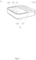
- Fig 1 is a schematic perspective view of a printer 1 at an angle in an exemplary embodiment of the present disclosure
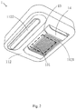
- Fig. 2 is a schematic perspective view of the printer 1 at another angle in an exemplary embodiment of the present disclosure
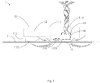
- Fig. 3 is a schematic diagram of an application scene of the printer 1 in an exemplary embodiment of the present disclosure
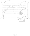
- Fig 5 is a schematic diagram of an application scene of a printer system in an exemplary embodiment of the present disclosure.
- the printer 1 includes a main body 11, an adsorption assembly 13, a printing assembly 12, and a moving assembly 14.
- the main body 11 includes a bottom part 112 adjacent to a surface 2 to be printed and a top part 111 opposite to the bottom part 112.
- the bottom part 112 is provided with an air inlet 1121 and an ink outlet 1122, and the top part 111 is provided with an air outlet 1111.
- the printing assembly 12 is assembled in the main body 11 and includes a main control 121 and an ink outlet mechanism 122 electrically connected to the main control 121.
- the ink outlet mechanism 122 is opened to the ink outlet 1122 so as to be controlled to implement printing operations on the surface 2 to be printed.
- the moving assembly 14 is assembled on the bottom part 112 of the main body 11 and is electrically connected to the main control 121 so as to be controlled to move along a planned path 21.
- the adsorption assembly 13 is assembled in the main body 11 and includes an air suction mechanism 131.
- An air intake passage of the air suction mechanism 131 is opened to the air inlet 1121, and an air outlet passage of the air suction mechanism 131 is opened to the air outlet 1111, so as to take out air from the bottom part 112 of the printer 1, such that the printer 1 is able to be absorbed onto the surface 2 to be printed by air pressure.
- the air suction mechanism 131 is configured to make the printer 1 to cling onto the surface 2 to be printed by air pressure, it is less influenced by environmental factors of the surface 2 to be printed.
- the printer 1 may be adsorbed onto the surface 2 to be printed in complicated environment, such as a horizontal plane, a vertical plane, a slope plane, or a ceiling plane, etc.
- the surface 2 to be printed may be printed in accordance with the planned path 21 by cooperating of a moving mechanism provided on the bottom part 112 of the main body 11 and the printing assembly 12. Therefore, the above improvement improves adaptability to the printing environment, the operation convenience and intelligence of the printer 1.
- the main control 121 can perform path planning according to actual environmental conditions of the surface 2 to be printed, and is associated with the moving assembly 14 and the ink outlet mechanism 122, to control the moving assembly 14 and the ink outlet mechanism 122 to work synchronously, thereby implement the printing of a preset graphic 32.
- the main control 121 can perform various functions, such as analyzing a distribution of the preset graphic 32, avoiding obstacles on the surface 2 to be printed, etc., according to the area of the surface 2 to be printed,
- the preset graphic 32 may be pre-stored on the main control 121, or data transmission of the preset graphic 32 may be realized by the association with an external control device 3 as well, which is not limited in the present disclosure.
- the following is an exemplary description of structures and assembly method of the printing assembly 12, the adsorption assembly 13, and the moving assembly 14, respectively.
- the adsorption assembly 13 includes the air suction mechanism 131 and a suction detecting mechanism 132.
- the air intake passage of the air suction mechanism 131 is opened to the air inlet 1121, and the air outlet passage of the air suction mechanism 131 is opened to the air outlet 1111, so as to take out the air from the bottom part 112 of the printer 1, such that the printer 1 is absorbed onto the surface 2 to be printed by air pressure.
- the suction detecting mechanism 132 is electrically connected to the air suction mechanism 131, so as to adjust the air suction amount of the air suction mechanism 131 in accordance with the magnitude of the absorption force while detecting the suction force of the printer 1.
- the printer 1 operating on an uneven wall surface is taken as an example.
- the printer 1 moving up and down may cause an increase or decrease in the air amount at the bottom part 112 of the printer 1, that is, the adsorption force applied on the printer 1 is thus changed.
- the adsorption force becomes small, information of the decrease in the adsorption force may be fed back to the air suction mechanism 131 by the suction detecting mechanism 132, so that the air suction amount of the air suction mechanism 131 is increased to increase the adsorption force.
- the suction detecting mechanism 132 when the adsorption force becomes large, information of the increase in the adsorption force may be fed back to the air suction mechanism 131 by the suction detecting mechanism 132, so that the air suction amount of the air suction mechanism 131 is decreased to decrease the adsorption force. Since a small adsorption force may cause that the printer 1 has a risk of falling during the working process, and a large adsorption force will form large friction between the printer 1 and the surface 2 to be printed, adjustment of the adsorption force by the suction detecting mechanism 132 improves safety of use and work efficiency of the printer 1.
- the air inlet 1121 is provided at the bottom part 112 of the main body 11 and configured to cooperate with the air suction mechanism 131 to take out the air of the bottom part 112 of the printer 1.
- the air inlet 1121 may include a plurality of strip-shaped holes arranged side by side. By the strip-shaped holes arranged side by side, external artistic appearance of the printer 1 may be improved, and the air inlet 1121 is prevented from being too large to excessively suck in excessive impurities, thereby improving working safety of the air suction mechanism 131.
- the air suction mechanism 131 may be a turbo or other devices capable of performing an air suction function, and the present disclosure is not limited thereto.
- the air suction mechanism 131 is the turbo
- the turbo matching the size of the printer 1 may be selected according to the size of the printer 1 to improve utilization of the internal space of the printer 1.
- the moving assembly 14 may be a variety of mechanisms such as a pedrail, a roller, etc., to move on various types of surfaces to be printed, and the present disclosure is not limited thereto.
- the moving assembly 14 may include at least one pedrail. The width of the pedrail matches the width of the bottom part 112 of the printer 1, and movement of the pedrail drives the printer 1 to move as a whole.
- the moving assembly 14 may include two pedrails as well, and the two pedrails are respectively arranged on both sides of the air inlet 1121, which avoids excessive occupation of the space of the bottom part 112 of the printer 1 by the pedrails, and improves stability and flexibility during the movement of the printer 1.
- material of the pedrail may be soft rubber such as PE (polyethylene) or PP (polypropylene).
- PE polyethylene
- PP polypropylene
- the pedrail with the material of soft rubber can cushion collision that the printer 1 encounters during a moving process, so as to avoid problems of falling caused by the collision, to increase stability of the movement of the printer 1.
- the printing assembly 12 includes the main control 121, the ink outlet mechanism 122, and an ink cartridge 123.
- the ink outlet mechanism 122 is electrically connected to the main control 121, so as to control the ink outlet mode by the main control 121 according to the graphic to be printed. Further, the ink outlet mechanism 122 is opened to the ink cartridge 123, to perform a derivation processing of ink in the ink cartridge 123.
- the ink cartridge 123 may be an integrated ink cartridge assembled in the printer 1, which may avoid structural interference on the movement of the printer 1 when a complicated structure such as an ink tube is adopted.
- the top part 111 of the main body 11 includes an opening and a cover plate 1112 that movably cooperates with the opening, and an interior part of the main body 11 is provided with an accommodating part 113 corresponding to the opening.
- the ink cartridge 123 is assembled in the accommodating part 113, the disassembly and replacement of the ink cartridge 123 may be realized by opening the cover plate 1112, and the ink cartridge 123 may be encapsulated in the accommodating part 113 by closing the cover plate 1112, thereby improving the convenience of disassembly, assembly and replacement of the ink cartridge 123.
- the ink outlet mechanism 122 is opened to the ink outlet 1122 of the bottom part 112 of the main body 11, so that the ink may be printed on the surface 2 to be printed through the ink outlet 1122.
- the bottom part 112 includes an edge region, and the ink outlet 1122 is arranged at the edge region. An arrangement of the ink outlet 1122 in the edge region reduces the interference of the moving mechanism and the air inlet 1121 on an ink outlet operation, thereby improving printing efficiency.
- the present disclosure further provides a printer system including the printer 1, as shown in Fig. 5 , which includes an external control device 3 and the printer 1.
- the external control device 3 includes a first association module 31.
- the main control 121 includes a second association module 15.
- the first association module 31 is associated with the second association module 15 to implement transmission of print data, which improves the convenience and control intelligence of the printer system.
- the printer 1 may be adsorbed onto the surface 2 to be printed of complicated environment, such as the horizontal plane, the vertical plane, the slope plane, or the ceiling plane, etc., by the air suction mechanism 131.
- the surface 2 to be printed may be printed in accordance with the planned path 21 by cooperating of the moving mechanism provided on the bottom part of the main body 11 and the printing assembly 12. Therefore, the above improvement improves the adaptability to the printing environment, the operation convenience and intelligence of the printer 1.
- the first association module 31 and the second association module 15 may be managed by a wireless network, so as to avoid the influence of a connection line on the operation of the printer 1, to improve the convenience of use.
- a specific work process may be that the second association module 15 of the printer 1 and the first association module 31 of the external control device 3 are connected via the wireless network, plane information, graphic information, etc., of the preset graphic 32 are transmitted to the main control 121 of the printer 1 through the external control device 3, and the main control 121 forms the planned path 21 based on the received information of the preset graphic 32.
- a user places the printer 1 on the starting point of the surface 2 to be printed, the printer 1 starts a printing work, that is, starts to be absorbed onto the plane and to draw graphic on the plane according to the planned path 21.
- a reminder module electrically connected to the main control 121 may be further provided for the printer 1. After the printer 1 completes drawing the graphic according to the planning path 21, the user is reminded to remove the printer 1 by the reminder module.
- the external control device 3 may be a mobile phone, a computer, etc., and the present disclosure is not limited thereto.
Landscapes
- Engineering & Computer Science (AREA)
- Chemical & Material Sciences (AREA)
- Combustion & Propulsion (AREA)
- Transportation (AREA)
- Mechanical Engineering (AREA)
- Physics & Mathematics (AREA)
- General Physics & Mathematics (AREA)
- Accessory Devices And Overall Control Thereof (AREA)
- Printers Characterized By Their Purpose (AREA)
- Ink Jet (AREA)
Abstract
Description
- The present disclosure relates to the field of printer technology, and particularly to a printer and a printer system.
- In the related art, a printer may be used to print a preset pattern on a specified wall surface. However, in order to complete printing on the entire wall surface, it is necessary to hold the printer by hand and to move it on the wall surface, or to set a moving pedrail for the printer, which increases operational complexity and structural complexity of the printer.
- The present invention provides a printer and a printer system to improve operational convenience of the printer while reducing structural complexity of the printer.
- According to a first aspect of the present invention, a printer includes: a main body, including a bottom part adjacent to a surface to be printed and a top part opposite to the bottom part, wherein the bottom part is provided with an air inlet and an ink outlet, and the top part is provided with an air outlet; an adsorption assembly, assembled in the main body and including an air suction mechanism, wherein an air intake passage of the air suction mechanism is opened to the air inlet, and an air outlet passage of the air suction mechanism is opened to the air outlet; a printing assembly, assembled in the main body and including a main control and an ink outlet mechanism electrically connected to the main control, wherein the ink outlet mechanism is opened to the ink outlet; and a moving assembly, assembled on the bottom part of the main body and is electrically connected to the main control.
- Optionally, the top part of the main body includes an opening and a cover plate that movably cooperates with the opening, an interior part of the main body is provided with an accommodating part corresponding to the opening, the printing assembly further includes an ink cartridge opened to the ink outlet mechanism, and the ink cartridge is assembled in the accommodating part.
- Optionally, the adsorption assembly further includes a suction detecting mechanism electrically connected to the air suction mechanism.
- Optionally, the bottom part includes an edge region, and the ink outlet is arranged at the edge region.
- Optionally, the air inlet includes a plurality of strip-shaped holes arranged side by side.
- Optionally, the air suction mechanism includes a turbo.
- Optionally, the moving assembly includes at least one pedrail.
- Optionally, the moving assembly includes two pedrails respectively arranged on both sides of the air inlet.
- Optionally, material of the pedrail includes soft rubber.
- According to a second aspect of the present invention, a printer system includes an external control device and the above printer controlled by the external control device, wherein the external control device includes a first association module, the main control in the printing assembly includes a second association module, and the first association module is associated with the second association module to implement transmission of print data.
- The technical solution provided by the present invention may include the following beneficial effects:
- According to the present invention, by providing the adsorption assembly and the moving assembly for the printer, providing the air inlet opened to the air intake passage of the air suction mechanism at the bottom of the main body, and providing the air inlet opened to the air outlet passage of the air suction mechanism at the bottom of the main body, the printer may be adsorbed onto the surface to be printed in complicated environment, such as the horizontal plane, the vertical plane, the slope plane, or the ceiling plane, etc., by the air suction mechanism. At the same time, the surface to be printed may be printed in accordance with the planned path by cooperating of the moving mechanism provided on the bottom part of the main body and the printing assembly. Therefore, the above improvement improves adaptability to the printing environment, operation convenience and intelligence of the printer.
- It shall be understood that the above general description and the following detailed description are merely exemplary and explanatory and are not intended to be restrictive of the present disclosure.
- The accompanying drawings, which are incorporated in and constitute a part of this specification, illustrate embodiments consistent with the disclosure, and together with the description, serve to explain the principle of the disclosure.
-
Fig 1 is a schematic perspective view of a printer at an angle in an exemplary embodiment of the present disclosure. -
Fig. 2 is a schematic perspective view of a printer at another angle in an exemplary embodiment of the present disclosure. -
Fig. 3 is a schematic diagram of an application scene of a printer in an exemplary embodiment of the present disclosure. -
Fig 4 is a schematic perspective view of a printer in another exemplary embodiment of the present disclosure. -
Fig 5 is a schematic diagram of an application scene of a printer system in another exemplary embodiment of the present disclosure. - Reference will now be made in detail to exemplary embodiments, examples of which are illustrated in the accompanying drawings. The following description refers to the accompanying drawings in which the same numbers in different drawings represent the same or similar elements unless otherwise represented. The implementations set forth in the following description of exemplary embodiments do not represent all implementations consistent with the present disclosure. Instead, they are merely examples of devices and methods consistent with aspects related to the present disclosure as recited in the appended claims.
- In the related art, effects of more and more wall surfaces are realized by printing, that is, using a printer to print a preset pattern on a designated wall surface. However, under normal circumstances, an area of the wall surface is pretty large, and circumstances of the slope and the flatness of the wall surface are complicated as well. In order to complete printing on the entire wall surface, the printer needs to be handheld to move on the wall, or a moving pedrail is set for the printer, which greatly increases operational complexity and structural complexity of the printer.
-
Fig 1 is a schematic perspective view of aprinter 1 at an angle in an exemplary embodiment of the present disclosure;Fig. 2 is a schematic perspective view of theprinter 1 at another angle in an exemplary embodiment of the present disclosure; andFig. 3 is a schematic diagram of an application scene of theprinter 1 in an exemplary embodiment of the present disclosure.Fig 5 is a schematic diagram of an application scene of a printer system in an exemplary embodiment of the present disclosure. Referring toFigs. 1-3 and5 , theprinter 1 includes amain body 11, anadsorption assembly 13, aprinting assembly 12, and a movingassembly 14. In the embodiment, themain body 11 includes abottom part 112 adjacent to asurface 2 to be printed and atop part 111 opposite to thebottom part 112. Thebottom part 112 is provided with anair inlet 1121 and anink outlet 1122, and thetop part 111 is provided with anair outlet 1111. Theprinting assembly 12 is assembled in themain body 11 and includes amain control 121 and anink outlet mechanism 122 electrically connected to themain control 121. Theink outlet mechanism 122 is opened to theink outlet 1122 so as to be controlled to implement printing operations on thesurface 2 to be printed. Themoving assembly 14 is assembled on thebottom part 112 of themain body 11 and is electrically connected to themain control 121 so as to be controlled to move along a plannedpath 21. Theadsorption assembly 13 is assembled in themain body 11 and includes anair suction mechanism 131. An air intake passage of theair suction mechanism 131 is opened to theair inlet 1121, and an air outlet passage of theair suction mechanism 131 is opened to theair outlet 1111, so as to take out air from thebottom part 112 of theprinter 1, such that theprinter 1 is able to be absorbed onto thesurface 2 to be printed by air pressure. - Since the
air suction mechanism 131 is configured to make theprinter 1 to cling onto thesurface 2 to be printed by air pressure, it is less influenced by environmental factors of thesurface 2 to be printed. Theprinter 1 may be adsorbed onto thesurface 2 to be printed in complicated environment, such as a horizontal plane, a vertical plane, a slope plane, or a ceiling plane, etc. At the same time, thesurface 2 to be printed may be printed in accordance with the plannedpath 21 by cooperating of a moving mechanism provided on thebottom part 112 of themain body 11 and theprinting assembly 12. Therefore, the above improvement improves adaptability to the printing environment, the operation convenience and intelligence of theprinter 1. - In the above embodiments, the
main control 121 can perform path planning according to actual environmental conditions of thesurface 2 to be printed, and is associated with themoving assembly 14 and theink outlet mechanism 122, to control the movingassembly 14 and theink outlet mechanism 122 to work synchronously, thereby implement the printing of apreset graphic 32. For example, themain control 121 can perform various functions, such as analyzing a distribution of thepreset graphic 32, avoiding obstacles on thesurface 2 to be printed, etc., according to the area of thesurface 2 to be printed, Thepreset graphic 32 may be pre-stored on themain control 121, or data transmission of thepreset graphic 32 may be realized by the association with anexternal control device 3 as well, which is not limited in the present disclosure. - The following is an exemplary description of structures and assembly method of the
printing assembly 12, theadsorption assembly 13, and themoving assembly 14, respectively. - As shown in
Fig. 1 ,Fig. 2 , andFig. 3 , theadsorption assembly 13 includes theair suction mechanism 131 and asuction detecting mechanism 132. The air intake passage of theair suction mechanism 131 is opened to theair inlet 1121, and the air outlet passage of theair suction mechanism 131 is opened to theair outlet 1111, so as to take out the air from thebottom part 112 of theprinter 1, such that theprinter 1 is absorbed onto thesurface 2 to be printed by air pressure. In the embodiment, thesuction detecting mechanism 132 is electrically connected to theair suction mechanism 131, so as to adjust the air suction amount of theair suction mechanism 131 in accordance with the magnitude of the absorption force while detecting the suction force of theprinter 1. - In an embodiment, the
printer 1 operating on an uneven wall surface is taken as an example. Theprinter 1 moving up and down may cause an increase or decrease in the air amount at thebottom part 112 of theprinter 1, that is, the adsorption force applied on theprinter 1 is thus changed. When the adsorption force becomes small, information of the decrease in the adsorption force may be fed back to theair suction mechanism 131 by thesuction detecting mechanism 132, so that the air suction amount of theair suction mechanism 131 is increased to increase the adsorption force. Similarly, when the adsorption force becomes large, information of the increase in the adsorption force may be fed back to theair suction mechanism 131 by thesuction detecting mechanism 132, so that the air suction amount of theair suction mechanism 131 is decreased to decrease the adsorption force. Since a small adsorption force may cause that theprinter 1 has a risk of falling during the working process, and a large adsorption force will form large friction between theprinter 1 and thesurface 2 to be printed, adjustment of the adsorption force by thesuction detecting mechanism 132 improves safety of use and work efficiency of theprinter 1. - In the above embodiments, the
air inlet 1121 is provided at thebottom part 112 of themain body 11 and configured to cooperate with theair suction mechanism 131 to take out the air of thebottom part 112 of theprinter 1. In the embodiment, theair inlet 1121 may include a plurality of strip-shaped holes arranged side by side. By the strip-shaped holes arranged side by side, external artistic appearance of theprinter 1 may be improved, and theair inlet 1121 is prevented from being too large to excessively suck in excessive impurities, thereby improving working safety of theair suction mechanism 131. - It should be noted that the
air suction mechanism 131 may be a turbo or other devices capable of performing an air suction function, and the present disclosure is not limited thereto. When theair suction mechanism 131 is the turbo, the turbo matching the size of theprinter 1 may be selected according to the size of theprinter 1 to improve utilization of the internal space of theprinter 1. - As shown in
Fig. 1 ,Fig. 2 , andFig. 3 , the movingassembly 14 may be a variety of mechanisms such as a pedrail, a roller, etc., to move on various types of surfaces to be printed, and the present disclosure is not limited thereto. When the movingassembly 14 is a pedrail, the movingassembly 14 may include at least one pedrail. The width of the pedrail matches the width of thebottom part 112 of theprinter 1, and movement of the pedrail drives theprinter 1 to move as a whole. Alternatively, the movingassembly 14 may include two pedrails as well, and the two pedrails are respectively arranged on both sides of theair inlet 1121, which avoids excessive occupation of the space of thebottom part 112 of theprinter 1 by the pedrails, and improves stability and flexibility during the movement of theprinter 1. - It should be noted that material of the pedrail may be soft rubber such as PE (polyethylene) or PP (polypropylene). The pedrail with the material of soft rubber can cushion collision that the
printer 1 encounters during a moving process, so as to avoid problems of falling caused by the collision, to increase stability of the movement of theprinter 1. - In the embodiment shown in
Fig. 4 , theprinting assembly 12 includes themain control 121, theink outlet mechanism 122, and anink cartridge 123. In the embodiment, theink outlet mechanism 122 is electrically connected to themain control 121, so as to control the ink outlet mode by themain control 121 according to the graphic to be printed. Further, theink outlet mechanism 122 is opened to theink cartridge 123, to perform a derivation processing of ink in theink cartridge 123. Theink cartridge 123 may be an integrated ink cartridge assembled in theprinter 1, which may avoid structural interference on the movement of theprinter 1 when a complicated structure such as an ink tube is adopted. - In the above embodiments, the
top part 111 of themain body 11 includes an opening and acover plate 1112 that movably cooperates with the opening, and an interior part of themain body 11 is provided with anaccommodating part 113 corresponding to the opening. Theink cartridge 123 is assembled in theaccommodating part 113, the disassembly and replacement of theink cartridge 123 may be realized by opening thecover plate 1112, and theink cartridge 123 may be encapsulated in theaccommodating part 113 by closing thecover plate 1112, thereby improving the convenience of disassembly, assembly and replacement of theink cartridge 123. - Further, the
ink outlet mechanism 122 is opened to theink outlet 1122 of thebottom part 112 of themain body 11, so that the ink may be printed on thesurface 2 to be printed through theink outlet 1122. In the embodiment, thebottom part 112 includes an edge region, and theink outlet 1122 is arranged at the edge region. An arrangement of theink outlet 1122 in the edge region reduces the interference of the moving mechanism and theair inlet 1121 on an ink outlet operation, thereby improving printing efficiency. - The present disclosure further provides a printer system including the
printer 1, as shown inFig. 5 , which includes anexternal control device 3 and theprinter 1. Theexternal control device 3 includes afirst association module 31. Themain control 121 includes asecond association module 15. Thefirst association module 31 is associated with thesecond association module 15 to implement transmission of print data, which improves the convenience and control intelligence of the printer system. - The
printer 1 may be adsorbed onto thesurface 2 to be printed of complicated environment, such as the horizontal plane, the vertical plane, the slope plane, or the ceiling plane, etc., by theair suction mechanism 131. At the same time, thesurface 2 to be printed may be printed in accordance with theplanned path 21 by cooperating of the moving mechanism provided on the bottom part of themain body 11 and theprinting assembly 12. Therefore, the above improvement improves the adaptability to the printing environment, the operation convenience and intelligence of theprinter 1. - In the above embodiments, the
first association module 31 and thesecond association module 15 may be managed by a wireless network, so as to avoid the influence of a connection line on the operation of theprinter 1, to improve the convenience of use. A specific work process may be that thesecond association module 15 of theprinter 1 and thefirst association module 31 of theexternal control device 3 are connected via the wireless network, plane information, graphic information, etc., of the preset graphic 32 are transmitted to themain control 121 of theprinter 1 through theexternal control device 3, and themain control 121 forms theplanned path 21 based on the received information of the preset graphic 32. A user places theprinter 1 on the starting point of thesurface 2 to be printed, theprinter 1 starts a printing work, that is, starts to be absorbed onto the plane and to draw graphic on the plane according to theplanned path 21. A reminder module electrically connected to themain control 121 may be further provided for theprinter 1. After theprinter 1 completes drawing the graphic according to theplanning path 21, the user is reminded to remove theprinter 1 by the reminder module. - It should be noted that the
external control device 3 may be a mobile phone, a computer, etc., and the present disclosure is not limited thereto. - After considering this description and practicing the embodiments disclosed here, those skilled in the art may easily think of other implementation of the present disclosure. The present disclosure intends to cover any variations, usage or adaptive change of these embodiments, and these variations, usage or adaptive change follow general principle of the present disclosure and include the common knowledge or the customary technical means in the technical field that is not disclosed in the present disclosure. The description and embodiments are only exemplary, and the real range and spirit of the present disclosure are defined by the following claims.
- It should be understood that the present disclosure is not limited to precise structures that are described above and shown in the accompanying drawings, and may be modified and changed variously without departing from the range of the present disclosure. The scope of the present disclosure is only defined by the appended claims.
Claims (10)
- A printer, comprising:a main body, comprising a bottom part adjacent to a surface to be printed and a top part opposite to the bottom part, wherein the bottom part is provided with an air inlet and an ink outlet, and the top part is provided with an air outlet;an adsorption assembly, assembled in the main body and comprising an air suction mechanism, wherein an air intake passage of the air suction mechanism is opened to the air inlet, and an air outlet passage of the air suction mechanism is opened to the air outlet;a printing assembly, assembled in the main body and comprising a main control and an ink outlet mechanism electrically connected to the main control, wherein the ink outlet mechanism is opened to the ink outlet; anda moving assembly, assembled on the bottom part of the main body and is electrically connected to the main control.
- The printer according to claim 1, wherein the top part of the main body comprises an opening and a cover plate that movably cooperates with the opening, an interior part of the main body is provided with an accommodating part corresponding to the opening, the printing assembly further comprises an ink cartridge opened to the ink outlet mechanism, and the ink cartridge is assembled in the accommodating part.
- The printer according to claim 1 or claim 2, wherein the adsorption assembly further comprises a suction detecting mechanism electrically connected to the air suction mechanism.
- The printer according to any one of the preceding claims, wherein the bottom part comprises an edge region, and the ink outlet is arranged at the edge region.
- The printer according to any one of the preceding claims, wherein the air inlet comprises a plurality of strip-shaped holes arranged side by side.
- The printer according to any one of the preceding claims, wherein the air suction mechanism comprises a turbo.
- The printer according to any one of the preceding claims, wherein the moving assembly comprises at least one pedrail.
- The printer according to claim 7, wherein the moving assembly comprises two pedrails respectively arranged on both sides of the air inlet.
- The printer according to claim 7 or claim 8, wherein material of the at least one pedrail comprises soft rubber.
- A printer system, comprising:an external control device; anda printer according to any one of claims 1-9, wherein the external control device comprises a first association module, the main control in the printing assembly comprises a second association module, and the first association module is associated with the second association module to implement transmission of print data.
Applications Claiming Priority (1)
| Application Number | Priority Date | Filing Date | Title |
|---|---|---|---|
| CN201811403915.1A CN109278424A (en) | 2018-11-23 | 2018-11-23 | Printers and Printer Systems |
Publications (2)
| Publication Number | Publication Date |
|---|---|
| EP3656565A1 true EP3656565A1 (en) | 2020-05-27 |
| EP3656565B1 EP3656565B1 (en) | 2021-10-27 |
Family
ID=65172538
Family Applications (1)
| Application Number | Title | Priority Date | Filing Date |
|---|---|---|---|
| EP19199277.5A Not-in-force EP3656565B1 (en) | 2018-11-23 | 2019-09-24 | Printer and printer system |
Country Status (7)
| Country | Link |
|---|---|
| US (1) | US10821737B2 (en) |
| EP (1) | EP3656565B1 (en) |
| JP (1) | JP6917466B2 (en) |
| KR (1) | KR102307126B1 (en) |
| CN (1) | CN109278424A (en) |
| RU (1) | RU2722460C1 (en) |
| WO (1) | WO2020103355A1 (en) |
Families Citing this family (4)
| Publication number | Priority date | Publication date | Assignee | Title |
|---|---|---|---|---|
| CN109278424A (en) | 2018-11-23 | 2019-01-29 | 北京小米移动软件有限公司 | Printers and Printer Systems |
| USD922949S1 (en) * | 2019-05-16 | 2021-06-22 | Beijing Xiaomi Mobile Software Co., Ltd. | Charger for dust mite controller |
| JP1681235S (en) * | 2020-04-10 | 2021-03-15 | Printer | |
| JP1698289S (en) * | 2020-09-10 | 2021-10-25 | printer |
Citations (1)
| Publication number | Priority date | Publication date | Assignee | Title |
|---|---|---|---|---|
| US9849693B1 (en) * | 2016-08-31 | 2017-12-26 | Fuji Xerox Co., Ltd. | Systems and methods for printing on large surface with portable printing devices |
Family Cites Families (21)
| Publication number | Priority date | Publication date | Assignee | Title |
|---|---|---|---|---|
| US6116707A (en) * | 1997-12-18 | 2000-09-12 | Electronics For Imaging, Inc. | Robotic plotter system |
| JP2944642B1 (en) * | 1998-07-08 | 1999-09-06 | 静岡日本電気株式会社 | Serial printer |
| JP2001033746A (en) * | 1999-07-26 | 2001-02-09 | Minolta Co Ltd | Structural face which enables reversible display, structural face display system and image recording device |
| TWI259149B (en) * | 2002-09-30 | 2006-08-01 | Canon Kk | Ink container and recording apparatus |
| JP2005170039A (en) * | 2003-11-20 | 2005-06-30 | Dainippon Screen Mfg Co Ltd | Printer and printing method |
| JP2005283898A (en) * | 2004-03-29 | 2005-10-13 | Canon Inc | Image forming apparatus and color balance adjusting method thereof |
| KR100740513B1 (en) * | 2006-04-20 | 2007-07-19 | 김대봉 | Building Wall Printing System |
| JP4948146B2 (en) * | 2006-12-15 | 2012-06-06 | キヤノン株式会社 | Inkjet recording device |
| CN201192930Y (en) * | 2008-04-22 | 2009-02-11 | 金宝电子工业股份有限公司 | Self-propelled printer with speed adjustment |
| JP5268542B2 (en) * | 2008-10-02 | 2013-08-21 | キヤノン株式会社 | Image processing apparatus and color processing method |
| KR20110072442A (en) * | 2009-12-22 | 2011-06-29 | 장미 | Wall climbing printer |
| JP2011240317A (en) * | 2010-05-21 | 2011-12-01 | Kansai Paint Co Ltd | Coating method |
| US20130171351A1 (en) * | 2011-07-18 | 2013-07-04 | Camtek Ltd. | Vacuum table for a printing device |
| US8696089B2 (en) * | 2012-06-11 | 2014-04-15 | Xerox Corporation | Portable printer for direct imaging on surfaces |
| CN105916692A (en) * | 2014-01-24 | 2016-08-31 | 祖塔实验室有限责任公司 | Self-propelled printer and self-propelled imprinter |
| JP6460674B2 (en) * | 2014-08-01 | 2019-01-30 | キヤノン株式会社 | Printing device |
| JP6344779B2 (en) * | 2016-11-02 | 2018-06-20 | 株式会社オンガエンジニアリング | Suction sliding type self-propelled inspection robot |
| CN108724962A (en) * | 2017-04-18 | 2018-11-02 | 徐建宁 | Vacuum cup facade printer |
| CN107933120A (en) * | 2017-12-28 | 2018-04-20 | 内江师范学院 | A kind of unlimited printer of intelligence |
| CN109278424A (en) * | 2018-11-23 | 2019-01-29 | 北京小米移动软件有限公司 | Printers and Printer Systems |
| CN209320505U (en) * | 2018-11-23 | 2019-08-30 | 北京小米移动软件有限公司 | Printer and printer system |
-
2018
- 2018-11-23 CN CN201811403915.1A patent/CN109278424A/en active Pending
-
2019
- 2019-03-08 RU RU2019127658A patent/RU2722460C1/en active
- 2019-03-08 KR KR1020197022659A patent/KR102307126B1/en not_active Expired - Fee Related
- 2019-03-08 WO PCT/CN2019/077558 patent/WO2020103355A1/en not_active Ceased
- 2019-03-08 JP JP2019541713A patent/JP6917466B2/en not_active Expired - Fee Related
- 2019-09-10 US US16/565,764 patent/US10821737B2/en active Active
- 2019-09-24 EP EP19199277.5A patent/EP3656565B1/en not_active Not-in-force
Patent Citations (1)
| Publication number | Priority date | Publication date | Assignee | Title |
|---|---|---|---|---|
| US9849693B1 (en) * | 2016-08-31 | 2017-12-26 | Fuji Xerox Co., Ltd. | Systems and methods for printing on large surface with portable printing devices |
Also Published As
| Publication number | Publication date |
|---|---|
| CN109278424A (en) | 2019-01-29 |
| RU2722460C1 (en) | 2020-06-01 |
| US10821737B2 (en) | 2020-11-03 |
| JP6917466B2 (en) | 2021-08-11 |
| US20200164654A1 (en) | 2020-05-28 |
| EP3656565B1 (en) | 2021-10-27 |
| JP2021509865A (en) | 2021-04-08 |
| WO2020103355A1 (en) | 2020-05-28 |
| KR102307126B1 (en) | 2021-10-01 |
| KR20200062077A (en) | 2020-06-03 |
Similar Documents
| Publication | Publication Date | Title |
|---|---|---|
| EP3656565B1 (en) | Printer and printer system | |
| US10543698B2 (en) | Printing apparatus and platen | |
| EP3122927B1 (en) | Recording apparatus and recording method | |
| KR102707770B1 (en) | Handheld printer, printing method, information processing method and printing device | |
| CN203775535U (en) | Substrate adsorption carrying platform | |
| US20150375548A1 (en) | Drawing apparatus and drawing control method thereof | |
| WO2011149269A3 (en) | Nail art device | |
| US9902154B2 (en) | Image printing apparatus | |
| CN209320505U (en) | Printer and printer system | |
| KR20130006957U (en) | apparatus for transcirption printing used hear of sublimation upon smart phone case | |
| CN214873684U (en) | Variable-size air suction device of printing equipment | |
| EP3085537B1 (en) | Liquid discharging apparatus | |
| US10913263B2 (en) | Control device controlling printer provided with head and carriage capable of moving at a plurality of different speeds | |
| CN102673188A (en) | Printer control method and printer drive program | |
| KR101206021B1 (en) | Movable labeling apparatus | |
| US10124608B2 (en) | Image printing apparatus | |
| CN111616488A (en) | Electronic equipment and printing equipment | |
| JP2025005243A (en) | Liquid ejection device | |
| US20250065652A1 (en) | Printing apparatus | |
| CN205139796U (en) | Handheld quick -witted docking station pops out device | |
| JP2023180602A (en) | Printing device, printing control method and program | |
| JP2017140817A (en) | Printer | |
| JP2024155492A (en) | Printing device | |
| JP2023090084A (en) | Printing device and suction method | |
| JP2021079568A (en) | Liquid composition application device |
Legal Events
| Date | Code | Title | Description |
|---|---|---|---|
| PUAI | Public reference made under article 153(3) epc to a published international application that has entered the european phase |
Free format text: ORIGINAL CODE: 0009012 |
|
| STAA | Information on the status of an ep patent application or granted ep patent |
Free format text: STATUS: THE APPLICATION HAS BEEN PUBLISHED |
|
| AK | Designated contracting states |
Kind code of ref document: A1 Designated state(s): AL AT BE BG CH CY CZ DE DK EE ES FI FR GB GR HR HU IE IS IT LI LT LU LV MC MK MT NL NO PL PT RO RS SE SI SK SM TR |
|
| AX | Request for extension of the european patent |
Extension state: BA ME |
|
| STAA | Information on the status of an ep patent application or granted ep patent |
Free format text: STATUS: REQUEST FOR EXAMINATION WAS MADE |
|
| 17P | Request for examination filed |
Effective date: 20201123 |
|
| RBV | Designated contracting states (corrected) |
Designated state(s): AL AT BE BG CH CY CZ DE DK EE ES FI FR GB GR HR HU IE IS IT LI LT LU LV MC MK MT NL NO PL PT RO RS SE SI SK SM TR |
|
| GRAP | Despatch of communication of intention to grant a patent |
Free format text: ORIGINAL CODE: EPIDOSNIGR1 |
|
| STAA | Information on the status of an ep patent application or granted ep patent |
Free format text: STATUS: GRANT OF PATENT IS INTENDED |
|
| INTG | Intention to grant announced |
Effective date: 20210601 |
|
| GRAS | Grant fee paid |
Free format text: ORIGINAL CODE: EPIDOSNIGR3 |
|
| GRAA | (expected) grant |
Free format text: ORIGINAL CODE: 0009210 |
|
| STAA | Information on the status of an ep patent application or granted ep patent |
Free format text: STATUS: THE PATENT HAS BEEN GRANTED |
|
| AK | Designated contracting states |
Kind code of ref document: B1 Designated state(s): AL AT BE BG CH CY CZ DE DK EE ES FI FR GB GR HR HU IE IS IT LI LT LU LV MC MK MT NL NO PL PT RO RS SE SI SK SM TR |
|
| REG | Reference to a national code |
Ref country code: GB Ref legal event code: FG4D |
|
| REG | Reference to a national code |
Ref country code: CH Ref legal event code: EP |
|
| REG | Reference to a national code |
Ref country code: AT Ref legal event code: REF Ref document number: 1441457 Country of ref document: AT Kind code of ref document: T Effective date: 20211115 |
|
| REG | Reference to a national code |
Ref country code: DE Ref legal event code: R096 Ref document number: 602019008680 Country of ref document: DE |
|
| REG | Reference to a national code |
Ref country code: IE Ref legal event code: FG4D |
|
| REG | Reference to a national code |
Ref country code: LT Ref legal event code: MG9D |
|
| REG | Reference to a national code |
Ref country code: NL Ref legal event code: MP Effective date: 20211027 |
|
| REG | Reference to a national code |
Ref country code: AT Ref legal event code: MK05 Ref document number: 1441457 Country of ref document: AT Kind code of ref document: T Effective date: 20211027 |
|
| PG25 | Lapsed in a contracting state [announced via postgrant information from national office to epo] |
Ref country code: RS Free format text: LAPSE BECAUSE OF FAILURE TO SUBMIT A TRANSLATION OF THE DESCRIPTION OR TO PAY THE FEE WITHIN THE PRESCRIBED TIME-LIMIT Effective date: 20211027 Ref country code: LT Free format text: LAPSE BECAUSE OF FAILURE TO SUBMIT A TRANSLATION OF THE DESCRIPTION OR TO PAY THE FEE WITHIN THE PRESCRIBED TIME-LIMIT Effective date: 20211027 Ref country code: FI Free format text: LAPSE BECAUSE OF FAILURE TO SUBMIT A TRANSLATION OF THE DESCRIPTION OR TO PAY THE FEE WITHIN THE PRESCRIBED TIME-LIMIT Effective date: 20211027 Ref country code: BG Free format text: LAPSE BECAUSE OF FAILURE TO SUBMIT A TRANSLATION OF THE DESCRIPTION OR TO PAY THE FEE WITHIN THE PRESCRIBED TIME-LIMIT Effective date: 20220127 Ref country code: AT Free format text: LAPSE BECAUSE OF FAILURE TO SUBMIT A TRANSLATION OF THE DESCRIPTION OR TO PAY THE FEE WITHIN THE PRESCRIBED TIME-LIMIT Effective date: 20211027 |
|
| PG25 | Lapsed in a contracting state [announced via postgrant information from national office to epo] |
Ref country code: IS Free format text: LAPSE BECAUSE OF FAILURE TO SUBMIT A TRANSLATION OF THE DESCRIPTION OR TO PAY THE FEE WITHIN THE PRESCRIBED TIME-LIMIT Effective date: 20220227 Ref country code: SE Free format text: LAPSE BECAUSE OF FAILURE TO SUBMIT A TRANSLATION OF THE DESCRIPTION OR TO PAY THE FEE WITHIN THE PRESCRIBED TIME-LIMIT Effective date: 20211027 Ref country code: PT Free format text: LAPSE BECAUSE OF FAILURE TO SUBMIT A TRANSLATION OF THE DESCRIPTION OR TO PAY THE FEE WITHIN THE PRESCRIBED TIME-LIMIT Effective date: 20220228 Ref country code: PL Free format text: LAPSE BECAUSE OF FAILURE TO SUBMIT A TRANSLATION OF THE DESCRIPTION OR TO PAY THE FEE WITHIN THE PRESCRIBED TIME-LIMIT Effective date: 20211027 Ref country code: NO Free format text: LAPSE BECAUSE OF FAILURE TO SUBMIT A TRANSLATION OF THE DESCRIPTION OR TO PAY THE FEE WITHIN THE PRESCRIBED TIME-LIMIT Effective date: 20220127 Ref country code: NL Free format text: LAPSE BECAUSE OF FAILURE TO SUBMIT A TRANSLATION OF THE DESCRIPTION OR TO PAY THE FEE WITHIN THE PRESCRIBED TIME-LIMIT Effective date: 20211027 Ref country code: LV Free format text: LAPSE BECAUSE OF FAILURE TO SUBMIT A TRANSLATION OF THE DESCRIPTION OR TO PAY THE FEE WITHIN THE PRESCRIBED TIME-LIMIT Effective date: 20211027 Ref country code: HR Free format text: LAPSE BECAUSE OF FAILURE TO SUBMIT A TRANSLATION OF THE DESCRIPTION OR TO PAY THE FEE WITHIN THE PRESCRIBED TIME-LIMIT Effective date: 20211027 Ref country code: GR Free format text: LAPSE BECAUSE OF FAILURE TO SUBMIT A TRANSLATION OF THE DESCRIPTION OR TO PAY THE FEE WITHIN THE PRESCRIBED TIME-LIMIT Effective date: 20220128 Ref country code: ES Free format text: LAPSE BECAUSE OF FAILURE TO SUBMIT A TRANSLATION OF THE DESCRIPTION OR TO PAY THE FEE WITHIN THE PRESCRIBED TIME-LIMIT Effective date: 20211027 |
|
| REG | Reference to a national code |
Ref country code: DE Ref legal event code: R097 Ref document number: 602019008680 Country of ref document: DE |
|
| PG25 | Lapsed in a contracting state [announced via postgrant information from national office to epo] |
Ref country code: SM Free format text: LAPSE BECAUSE OF FAILURE TO SUBMIT A TRANSLATION OF THE DESCRIPTION OR TO PAY THE FEE WITHIN THE PRESCRIBED TIME-LIMIT Effective date: 20211027 Ref country code: SK Free format text: LAPSE BECAUSE OF FAILURE TO SUBMIT A TRANSLATION OF THE DESCRIPTION OR TO PAY THE FEE WITHIN THE PRESCRIBED TIME-LIMIT Effective date: 20211027 Ref country code: RO Free format text: LAPSE BECAUSE OF FAILURE TO SUBMIT A TRANSLATION OF THE DESCRIPTION OR TO PAY THE FEE WITHIN THE PRESCRIBED TIME-LIMIT Effective date: 20211027 Ref country code: EE Free format text: LAPSE BECAUSE OF FAILURE TO SUBMIT A TRANSLATION OF THE DESCRIPTION OR TO PAY THE FEE WITHIN THE PRESCRIBED TIME-LIMIT Effective date: 20211027 Ref country code: DK Free format text: LAPSE BECAUSE OF FAILURE TO SUBMIT A TRANSLATION OF THE DESCRIPTION OR TO PAY THE FEE WITHIN THE PRESCRIBED TIME-LIMIT Effective date: 20211027 Ref country code: CZ Free format text: LAPSE BECAUSE OF FAILURE TO SUBMIT A TRANSLATION OF THE DESCRIPTION OR TO PAY THE FEE WITHIN THE PRESCRIBED TIME-LIMIT Effective date: 20211027 |
|
| PLBE | No opposition filed within time limit |
Free format text: ORIGINAL CODE: 0009261 |
|
| STAA | Information on the status of an ep patent application or granted ep patent |
Free format text: STATUS: NO OPPOSITION FILED WITHIN TIME LIMIT |
|
| 26N | No opposition filed |
Effective date: 20220728 |
|
| PG25 | Lapsed in a contracting state [announced via postgrant information from national office to epo] |
Ref country code: AL Free format text: LAPSE BECAUSE OF FAILURE TO SUBMIT A TRANSLATION OF THE DESCRIPTION OR TO PAY THE FEE WITHIN THE PRESCRIBED TIME-LIMIT Effective date: 20211027 |
|
| PG25 | Lapsed in a contracting state [announced via postgrant information from national office to epo] |
Ref country code: SI Free format text: LAPSE BECAUSE OF FAILURE TO SUBMIT A TRANSLATION OF THE DESCRIPTION OR TO PAY THE FEE WITHIN THE PRESCRIBED TIME-LIMIT Effective date: 20211027 |
|
| PG25 | Lapsed in a contracting state [announced via postgrant information from national office to epo] |
Ref country code: MC Free format text: LAPSE BECAUSE OF FAILURE TO SUBMIT A TRANSLATION OF THE DESCRIPTION OR TO PAY THE FEE WITHIN THE PRESCRIBED TIME-LIMIT Effective date: 20211027 |
|
| REG | Reference to a national code |
Ref country code: CH Ref legal event code: PL |
|
| REG | Reference to a national code |
Ref country code: BE Ref legal event code: MM Effective date: 20220930 |
|
| PG25 | Lapsed in a contracting state [announced via postgrant information from national office to epo] |
Ref country code: IT Free format text: LAPSE BECAUSE OF FAILURE TO SUBMIT A TRANSLATION OF THE DESCRIPTION OR TO PAY THE FEE WITHIN THE PRESCRIBED TIME-LIMIT Effective date: 20211027 |
|
| P01 | Opt-out of the competence of the unified patent court (upc) registered |
Effective date: 20230523 |
|
| PG25 | Lapsed in a contracting state [announced via postgrant information from national office to epo] |
Ref country code: LU Free format text: LAPSE BECAUSE OF NON-PAYMENT OF DUE FEES Effective date: 20220924 |
|
| PG25 | Lapsed in a contracting state [announced via postgrant information from national office to epo] |
Ref country code: LI Free format text: LAPSE BECAUSE OF NON-PAYMENT OF DUE FEES Effective date: 20220930 Ref country code: IE Free format text: LAPSE BECAUSE OF NON-PAYMENT OF DUE FEES Effective date: 20220924 Ref country code: CH Free format text: LAPSE BECAUSE OF NON-PAYMENT OF DUE FEES Effective date: 20220930 |
|
| PG25 | Lapsed in a contracting state [announced via postgrant information from national office to epo] |
Ref country code: BE Free format text: LAPSE BECAUSE OF NON-PAYMENT OF DUE FEES Effective date: 20220930 |
|
| PGFP | Annual fee paid to national office [announced via postgrant information from national office to epo] |
Ref country code: GB Payment date: 20230920 Year of fee payment: 5 |
|
| PGFP | Annual fee paid to national office [announced via postgrant information from national office to epo] |
Ref country code: FR Payment date: 20230928 Year of fee payment: 5 Ref country code: DE Payment date: 20230920 Year of fee payment: 5 |
|
| PG25 | Lapsed in a contracting state [announced via postgrant information from national office to epo] |
Ref country code: CY Free format text: LAPSE BECAUSE OF FAILURE TO SUBMIT A TRANSLATION OF THE DESCRIPTION OR TO PAY THE FEE WITHIN THE PRESCRIBED TIME-LIMIT Effective date: 20211027 |
|
| PG25 | Lapsed in a contracting state [announced via postgrant information from national office to epo] |
Ref country code: MK Free format text: LAPSE BECAUSE OF FAILURE TO SUBMIT A TRANSLATION OF THE DESCRIPTION OR TO PAY THE FEE WITHIN THE PRESCRIBED TIME-LIMIT Effective date: 20211027 Ref country code: HU Free format text: LAPSE BECAUSE OF FAILURE TO SUBMIT A TRANSLATION OF THE DESCRIPTION OR TO PAY THE FEE WITHIN THE PRESCRIBED TIME-LIMIT; INVALID AB INITIO Effective date: 20190924 |
|
| REG | Reference to a national code |
Ref country code: DE Ref legal event code: R082 Ref document number: 602019008680 Country of ref document: DE Representative=s name: DEHNS GERMANY PARTNERSCHAFT MBB, DE |
|
| PG25 | Lapsed in a contracting state [announced via postgrant information from national office to epo] |
Ref country code: MT Free format text: LAPSE BECAUSE OF FAILURE TO SUBMIT A TRANSLATION OF THE DESCRIPTION OR TO PAY THE FEE WITHIN THE PRESCRIBED TIME-LIMIT Effective date: 20211027 |
|
| REG | Reference to a national code |
Ref country code: DE Ref legal event code: R119 Ref document number: 602019008680 Country of ref document: DE |
|
| GBPC | Gb: european patent ceased through non-payment of renewal fee |
Effective date: 20240924 |
|
| PG25 | Lapsed in a contracting state [announced via postgrant information from national office to epo] |
Ref country code: DE Free format text: LAPSE BECAUSE OF NON-PAYMENT OF DUE FEES Effective date: 20250401 |
|
| PG25 | Lapsed in a contracting state [announced via postgrant information from national office to epo] |
Ref country code: GB Free format text: LAPSE BECAUSE OF NON-PAYMENT OF DUE FEES Effective date: 20240924 |
|
| PG25 | Lapsed in a contracting state [announced via postgrant information from national office to epo] |
Ref country code: FR Free format text: LAPSE BECAUSE OF NON-PAYMENT OF DUE FEES Effective date: 20240930 |
|
| PG25 | Lapsed in a contracting state [announced via postgrant information from national office to epo] |
Ref country code: TR Free format text: LAPSE BECAUSE OF FAILURE TO SUBMIT A TRANSLATION OF THE DESCRIPTION OR TO PAY THE FEE WITHIN THE PRESCRIBED TIME-LIMIT Effective date: 20211027 |