EP3655674B1 - Kupplung und verfahren zu ihrer herstellung - Google Patents
Kupplung und verfahren zu ihrer herstellung Download PDFInfo
- Publication number
- EP3655674B1 EP3655674B1 EP18745845.0A EP18745845A EP3655674B1 EP 3655674 B1 EP3655674 B1 EP 3655674B1 EP 18745845 A EP18745845 A EP 18745845A EP 3655674 B1 EP3655674 B1 EP 3655674B1
- Authority
- EP
- European Patent Office
- Prior art keywords
- coupling
- hollow cylinder
- coupling half
- case
- bore
- Prior art date
- Legal status (The legal status is an assumption and is not a legal conclusion. Google has not performed a legal analysis and makes no representation as to the accuracy of the status listed.)
- Active
Links
Images
Classifications
-
- F—MECHANICAL ENGINEERING; LIGHTING; HEATING; WEAPONS; BLASTING
- F16—ENGINEERING ELEMENTS AND UNITS; GENERAL MEASURES FOR PRODUCING AND MAINTAINING EFFECTIVE FUNCTIONING OF MACHINES OR INSTALLATIONS; THERMAL INSULATION IN GENERAL
- F16D—COUPLINGS FOR TRANSMITTING ROTATION; CLUTCHES; BRAKES
- F16D1/00—Couplings for rigidly connecting two coaxial shafts or other movable machine elements
- F16D1/02—Couplings for rigidly connecting two coaxial shafts or other movable machine elements for connecting two abutting shafts or the like
-
- F—MECHANICAL ENGINEERING; LIGHTING; HEATING; WEAPONS; BLASTING
- F16—ENGINEERING ELEMENTS AND UNITS; GENERAL MEASURES FOR PRODUCING AND MAINTAINING EFFECTIVE FUNCTIONING OF MACHINES OR INSTALLATIONS; THERMAL INSULATION IN GENERAL
- F16D—COUPLINGS FOR TRANSMITTING ROTATION; CLUTCHES; BRAKES
- F16D3/00—Yielding couplings, i.e. with means permitting movement between the connected parts during the drive
- F16D3/16—Universal joints in which flexibility is produced by means of pivots or sliding or rolling connecting parts
- F16D3/18—Universal joints in which flexibility is produced by means of pivots or sliding or rolling connecting parts the coupling parts (1) having slidably-interengaging teeth
- F16D3/185—Universal joints in which flexibility is produced by means of pivots or sliding or rolling connecting parts the coupling parts (1) having slidably-interengaging teeth radial teeth connecting concentric inner and outer coupling parts
-
- F—MECHANICAL ENGINEERING; LIGHTING; HEATING; WEAPONS; BLASTING
- F16—ENGINEERING ELEMENTS AND UNITS; GENERAL MEASURES FOR PRODUCING AND MAINTAINING EFFECTIVE FUNCTIONING OF MACHINES OR INSTALLATIONS; THERMAL INSULATION IN GENERAL
- F16D—COUPLINGS FOR TRANSMITTING ROTATION; CLUTCHES; BRAKES
- F16D13/00—Friction clutches
-
- Y—GENERAL TAGGING OF NEW TECHNOLOGICAL DEVELOPMENTS; GENERAL TAGGING OF CROSS-SECTIONAL TECHNOLOGIES SPANNING OVER SEVERAL SECTIONS OF THE IPC; TECHNICAL SUBJECTS COVERED BY FORMER USPC CROSS-REFERENCE ART COLLECTIONS [XRACs] AND DIGESTS
- Y10—TECHNICAL SUBJECTS COVERED BY FORMER USPC
- Y10S—TECHNICAL SUBJECTS COVERED BY FORMER USPC CROSS-REFERENCE ART COLLECTIONS [XRACs] AND DIGESTS
- Y10S264/00—Plastic and nonmetallic article shaping or treating: processes
- Y10S264/77—Processes of molding urethanes
-
- Y—GENERAL TAGGING OF NEW TECHNOLOGICAL DEVELOPMENTS; GENERAL TAGGING OF CROSS-SECTIONAL TECHNOLOGIES SPANNING OVER SEVERAL SECTIONS OF THE IPC; TECHNICAL SUBJECTS COVERED BY FORMER USPC CROSS-REFERENCE ART COLLECTIONS [XRACs] AND DIGESTS
- Y10—TECHNICAL SUBJECTS COVERED BY FORMER USPC
- Y10S—TECHNICAL SUBJECTS COVERED BY FORMER USPC CROSS-REFERENCE ART COLLECTIONS [XRACs] AND DIGESTS
- Y10S29/00—Metal working
- Y10S29/023—Method or apparatus with knurling
-
- Y—GENERAL TAGGING OF NEW TECHNOLOGICAL DEVELOPMENTS; GENERAL TAGGING OF CROSS-SECTIONAL TECHNOLOGIES SPANNING OVER SEVERAL SECTIONS OF THE IPC; TECHNICAL SUBJECTS COVERED BY FORMER USPC CROSS-REFERENCE ART COLLECTIONS [XRACs] AND DIGESTS
- Y10—TECHNICAL SUBJECTS COVERED BY FORMER USPC
- Y10S—TECHNICAL SUBJECTS COVERED BY FORMER USPC CROSS-REFERENCE ART COLLECTIONS [XRACs] AND DIGESTS
- Y10S464/00—Rotary shafts, gudgeons, housings, and flexible couplings for rotary shafts
- Y10S464/90—Electrically insulative member
-
- Y—GENERAL TAGGING OF NEW TECHNOLOGICAL DEVELOPMENTS; GENERAL TAGGING OF CROSS-SECTIONAL TECHNOLOGIES SPANNING OVER SEVERAL SECTIONS OF THE IPC; TECHNICAL SUBJECTS COVERED BY FORMER USPC CROSS-REFERENCE ART COLLECTIONS [XRACs] AND DIGESTS
- Y10—TECHNICAL SUBJECTS COVERED BY FORMER USPC
- Y10T—TECHNICAL SUBJECTS COVERED BY FORMER US CLASSIFICATION
- Y10T403/00—Joints and connections
- Y10T403/47—Molded joint
- Y10T403/472—Molded joint including mechanical interlock
Definitions
- the invention relates to the field of mechanical engineering and relates to a coupling such as that used for the transmission of torque between two machine shafts, for example as a tooth coupling, flange coupling, annular disc coupling, plate coupling, all-metal coupling, diaphragm coupling, multi-plate coupling, friction couplings or combination couplings, for example in vehicle drives, in particular rail vehicle drives Can be used, as well as a method for their production.
- a coupling such as that used for the transmission of torque between two machine shafts, for example as a tooth coupling, flange coupling, annular disc coupling, plate coupling, all-metal coupling, diaphragm coupling, multi-plate coupling, friction couplings or combination couplings, for example in vehicle drives, in particular rail vehicle drives Can be used, as well as a method for their production.
- Couplings are well known from the prior art. They are used to transfer torque from one shaft to another. Such couplings can be, for example, rigid or elastic couplings or switchable or non-switchable couplings. Couplings are also used for a rigid, torsionally rigid, elastic, torsionally elastic and / or movable connection between two shafts, with the couplings being able to compensate for torque surges and / or angular errors between the shafts.
- Such couplings are used, among other things, in the drive trains of vehicles such as cars, trucks, commercial vehicles, buses or rail vehicles. You are in the drive connections between a drive unit, for example a motor, and a work machine are directly integrated or can be switched into such a connection.
- a tooth coupling is known, with a first coupling section to be connected to the drive shaft and a second coupling section to be connected to the output shaft, at least one of the two coupling sections having driving teeth with internal teeth and an external teeth engaging therein, and an electrically connecting the two coupling portions with one another mutually insulating intermediate tube made of an electrically insulating material.
- an electrically insulating material is advantageously a fiber-reinforced plastic.
- the coupling hub is divided into a ring-like inner hub part for receiving at least one shaft component and into a ring-like outer hub part with an opening delimited by an inner surface into which the inner hub part is introduced, wherein the hub inner part is Inner part has an outer jacket surface which is in connection with the inner surface of the hub outer part, wherein an electrical insulation layer is located between the outer jacket surface of the hub inner part and the inner surface of the hub outer part, which is in the form of the insulation layer carrier (s) of the inner hub part and / or in the form of the outer hub part in front of a further assembly is applied.
- the insulation layer advantageously consists of a ceramic material and has a layer thickness that is significantly smaller than the thickness of the insulation layer carrier.
- An electrically insulating shaft connection element in which an outer shaft element with an inner opening, wherein an inner surface of the outer shaft element is formed in the inner opening, an inner shaft element with an outer surface of the inner shaft element, which is inserted into the inner opening of the outer shaft element by means of a press fit
- the inner surface of the outer shaft element and / or the outer surface of the inner shaft element have an electrical insulation coating which electrically insulates the outer shaft element and the inner shaft element from one another.
- a clutch for transmitting a torque and a vehicle drive train in particular for a rail vehicle, are known.
- This coupling comprises a first coupling half that can be connected to a drive, a second coupling half that can be connected to a working machine, at least one of the coupling halves is divided into two parts, including a first part and a second part, the two parts are arranged without contact with each other, see above that there is no current flow between the two, the two parts delimit a cavity containing at least one electrically insulating body, the cavity and the body are designed and arranged in such a way that a torque is transmitted from one part to the other part during operation.
- a disadvantage of the solutions of the prior art is that with the insulation layers for electrical insulation between the drive and output sides of a clutch, the electrical contact is not sufficiently interrupted to prevent flashover, since in particular the achievable capacities of the insulation layers are too high .
- the object of the present invention is to specify a coupling with which the electrical contact between the drive and output sides of the coupling is reliably prevented, and a simple and inexpensive method for its production.
- the coupling is advantageously a tooth coupling, link coupling, annular disc coupling, flange coupling, friction coupling or membrane coupling.
- the first hollow cylinder and the coupling half are also advantageously made of a metallic material, at least in the region of the bore.
- the second hollow cylinder also advantageously consists of an elastomer, duromer or thermoplastic, and also advantageously of epoxy resin, polyoxymethylene, polyetheretherketone, polyamide, polyurethane or glass fiber reinforced plastics.
- the material of the second hollow cylinder also advantageously has a dielectric constant or permittivity of a maximum of 9.
- the second hollow cylinder has a wall thickness of at least 1 mm.
- the shape of the knurling on the lateral surfaces of the first hollow cylinder and the bore in the coupling half is arranged essentially parallel to the axis of rotation of the drive or output shaft.
- the shape of the knurling on the outer surfaces of the first hollow cylinder and the bore in the coupling half is arranged at an angle between 0 ° and 90 ° to the axis of rotation of the drive or output shaft.
- the coupling half and the two hollow cylinders have positive and non-positive contact with one another and with the inner surface of the bore, or positive and integral contact or positive, non-positive and integral contact with one another.
- the knurling is present at least over the entire circumference of the inner and outer circumferential surface of the first hollow cylinder and the inner circumferential surface of the bore of the coupling half, partially or completely over the entire height of the hollow cylinder and the bore.
- the knurling is uniform on at least one lateral surface.
- the second hollow cylinder has a knurling partially or completely on the inner and / or outer circumferential surface.
- the inner jacket surface of the first hollow cylinder corresponds to the shape of the outer jacket surface of the drive or output shaft and all other jacket surfaces of the first and second hollow cylinder and the bore correspond at least to the shape of the jacket surfaces in contact with it, by one to generate non-positive, positive or material connection.
- the outer circumferential surface of the first hollow cylinder, the inner and / or outer circumferential surface of the second hollow cylinder and the inner circumferential surface of the bore have a conical or stepped shape and / or the diameter of the hollow cylinder and / or the bore is the same or over its length is different and the diameter is round, ellipsoidal or polygonal and / or the end faces of the second hollow cylinder at the end faces and / or the outer surfaces of the first, inner hollow cylinder and coupling half end with a bore and realize the electrical insulation of the first hollow cylinder and coupling half.
- a method for producing a coupling is described in claim 13.
- the knurling is made by knurling, pressing, thread cutting, turning, milling or embossing on the lateral surfaces of the first hollow cylinder and the bore in the coupling half.
- the electrically insulating material of the second hollow cylinder is likewise advantageously introduced in solid, pasty, liquid or molten form.
- a polymer material such as an elastomer, a duromer or a thermoplastic is also advantageously introduced as the electrically insulating material of the second hollow cylinder.
- the material of the second hollow cylinder is also advantageously pressed or injected into the space between the inner hollow cylinder and the bore in the coupling half.
- the present invention specifies a coupling with which electrical contact between the drive and output sides of the coupling is reliably prevented, as well as a simple and inexpensive method for its production.
- a coupling that consists of at least one coupling half on the drive side and one coupling half on the output side.
- a coupling can advantageously be a tooth coupling, annular disk coupling, tab coupling, flange coupling, membrane coupling or combination coupling.
- At least one coupling half has, starting from the drive or output shaft and connected to it in a form-fitting, non-positive and / or cohesive manner, at least two hollow cylinders arranged one above the other and interconnected in a form-fitting, non-positive and / or cohesive manner.
- a hollow cylinder is basically to be understood as a straight circular cylinder which has a bore along its axis.
- the outer shape of the jacket surfaces of the hollow cylinder can be designed differently.
- the inner and / or outer circumferential surfaces of the hollow cylinders can, for example, have a conical or stepped shape and the inner and / or outer diameter of the hollow cylinder can be the same or different over their length, and the shape of the diameter can also be round, ellipsoidal or polygonal and change over the length of the hollow cylinder.
- the second hollow cylinder not only realizes the electrical insulation of the inner, first hollow cylinder and coupling half on the front side, but also in the area of the jacket surfaces, for example in an angled form, so that the outer jacket surface of the coupling half is partly the material of the coupling half , the material of the second hollow cylinder and the material of the first, inner hollow cylinder.
- the two hollow cylinders are arranged directly one above the other, so that the first, inner hollow cylinder has the smallest inner diameter, which is the diameter corresponds to the input or output shaft.
- the second, middle hollow cylinder has an inner diameter which corresponds to the outer diameter of the first, inner hollow cylinder.
- the middle, second hollow cylinder is arranged in a bore of the coupling half, which is arranged essentially parallel to the axis of rotation of the drive or output shaft in the coupling half.
- the outer diameter of the second, central hollow cylinder corresponds to the inner diameter of the bore.
- first hollow cylinder and the coupling half are made of electrically conductive material, at least in the region of the bore, and the second hollow cylinder is made of electrically insulating material.
- Essentially metallic material is present as the electrically conductive material.
- Polymer materials such as elastomers, duromers and / or thermoplastics are used as electrically insulating material.
- Such polymer materials advantageously consist of epoxy resin, polyoxymethylene (POM), polyetheretherketone (PEEK), polyamide (PA), polyurethane (PU) or are glass fiber reinforced plastics.
- At least the first hollow cylinder has at least partially knurling on at least its outer circumferential surface, on the side facing away from the drive or output shaft, and at least the bore on its inner circumferential surface facing the drive or output shaft, likewise at least partially knurled.
- knurling should be understood to mean a circumferential shape deviation of the surface produced by means of knurling, pressing, thread cutting, turning, milling or embossing, which has been embossed into a metal body of revolution.
- the shape of the knurling on the lateral surfaces of the first hollow cylinder and the bore is advantageously essentially parallel or at an angle arranged between 0 ° and 90 ° to the axis of rotation of the drive or output shaft.
- the knurling is advantageously present at least over the entire circumference of the outer circumferential surface of the first hollow cylinder and the inner circumferential surface of the bore partially or completely over the entire height of the hollow cylinder and the bore.
- Uniform knurling on a lateral surface is also advantageous.
- the second hollow cylinder also has knurling partially or completely on the inner and / or outer circumferential surface.
- the second hollow cylinder has an essentially complete, at least form-fitting contact at least over the entire circumference with the outer circumferential surface of the first and the inner circumferential surface of the bore.
- the two hollow cylinders advantageously have a form-fitting and force-fitting contact or a form-fitting and material-fitting contact or a form-fitting, force-fitting and material-fitting contact with one another and also with respect to the bore.
- frictional engagement is to be understood as a non-positive connection in which a normal force is exerted on the surfaces to be connected and the mutual displacement of the surfaces to be connected due to friction is prevented.
- positive locking is to be understood as a positive connection in which the mechanical interlocking of at least two connection partners enables a force transmission due to a geometrically precisely fitting shape of the connection partners. A loosening of the connection partner cannot take place without or with interrupted power transmission.
- cohesive connection is to be understood as a material connection in which the connection partners are held together by atomic or molecular forces, the material connection being a non-detachable connection that can only be separated by destroying the connecting means.
- the electrically insulating material is selected with a dielectric constant or permittivity of a maximum of 9.
- the electrical capacitance between two electrically conductive bodies isolated from one another is determined by the dielectric constant of the insulating medium and the geometry of the electrically conductive body.
- the permittivity ⁇ also called dielectric conductivity or dielectric function, indicates the permeability of a certain material for electrical fields in electrodynamics and also in electrostatics.
- the electrical resistance in electrical engineering is a measure of the electrical voltage that is required to allow a certain electrical current to flow through an electrical conductor (component, circuit).
- the volume resistance should be> 1 * 10 10 ⁇ cm.
- the coupling according to the invention is produced according to the invention by a method in which at least two coupling halves are produced and at least one coupling half is produced from at least two hollow cylinders arranged one above the other in a bore of a coupling half.
- the first, inner hollow cylinder and the second coupling half are made of an electrically conductive material, at least in the area of the bore.
- At least the outer surface of the inner hollow cylinder and the inner surface of the bore are provided with knurling.
- the knurling can advantageously be introduced onto the lateral surfaces of the first hollow cylinder and the bore by means of knurling, pressing, thread cutting, turning, milling or embossing.
- the second, middle hollow cylinder made of an electrically insulating material is then introduced into the space between the inner hollow cylinder and the bore in the coupling half with essentially complete, at least positive, contact.
- a polymer material such as an elastomer, a duromer or a thermoplastic, can advantageously be introduced as the electrically insulating material of the second hollow cylinder.
- the electrically insulating material of the second hollow cylinder can be introduced in solid, pasty, liquid or molten form.
- the introduction can advantageously take place by pressing in or injecting.
- a further advantage of the solutions according to the invention is that, particularly in the case of a tooth coupling, the arrangement of the electrical insulation previously implemented in the prior art improves with the solution according to the invention.
- the solution according to the invention does not create any hollow spaces that are not functionally necessary, whereby the reliable transmission of a torque between two machine shafts is realized.
- the costly application of expensive ceramic or other electrically insulating layers to parts of the coupling can be avoided and, according to the invention, a uniform and uniform introduction of an electrically insulating material can be realized.
- the solution according to the invention also has the advantage that the hollow cylinders form very homogeneous layers and uniform layer thicknesses from the electrically insulating material, so that the electrical properties of the entire coupling are the same and equally good at all points.
- the hollow cylinder made of the electrically insulating material is positioned at a point within one or more coupling halves that does not restrict other coupling parts either in their function or in their effect.
- the hollow cylinder made of the electrically insulating material can also be arranged at a considerable distance from, for example, a toothing of a toothed coupling, which is particularly beneficial in that, in addition to the desired electrical insulation, thermal insulation is largely prevented, which does not hinder the dissipation of heat and thus the coupling temperatures not increased.
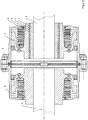
- a tooth coupling 1 which is used to connect an input and output shaft 2, 3.
- the drive shaft 2 can, for example, be a motor shaft and the output shaft 3 can be a transmission shaft for a vehicle.
- the tooth coupling 1 essentially consists of two coupling halves 4, 5, one on the drive side 2 and the other on the driven side 3.
- the coupling half 4 on the drive side 2 is unchanged compared to toothed couplings according to the prior art.
- the coupling half 5 on the output side 3 has the structure according to the invention.
- the first, inner hollow cylinder 6 made of steel has an inside diameter which corresponds to the outside diameter of the output shaft 3.
- the wall thickness of the first hollow cylinder 6 is 14 mm and the length is 65 mm.
- a knurling 7 in the form of ribs is introduced by means of knurls, which are arranged parallel to the axis of rotation of the output shaft 3, on the entire outer circumferential surface of the first hollow cylinder 6.
- the ribs, which are arranged parallel to one another, have a height of 0.6 mm and a spacing of 0.6 mm from one another.
- a bore in the coupling half 5 of the toothed coupling 1 is arranged around the first hollow cylinder 6 and has been introduced into the coupling half 5 with the output shaft 3 in a rotationally symmetrical manner.
- the diameter of the bore is 5 mm larger than the outer diameter of the first hollow cylinder 6.
- the coupling half 5 in the area of the bore is also made of steel.
- the bore has a knurling 9 on the entire inner circumferential surface, which has the shape of ribs.
- the ribs are arranged parallel to one another and parallel to the axis of rotation of the output shaft 3.
- the first hollow cylinder 6 is fastened in the bore on a base while maintaining a distance of 5 mm all around and a paste epoxy resin is injected into the space between the first hollow cylinder 6 and the bore at a temperature of 120 ° C and the space is completely filled. After the epoxy resin has cured, any protruding parts of the resin are removed. The cured epoxy resin forms the second hollow cylinder 8.
- the wall thickness of the second hollow cylinder 8 is 5 mm.
- the dielectric constant of the epoxy resin is 4.3.
- the toothed coupling 1 according to the invention reliably prevents electrical contact between the drive and output sides of the coupling, and can be produced simply and inexpensively.
Landscapes
- Engineering & Computer Science (AREA)
- General Engineering & Computer Science (AREA)
- Mechanical Engineering (AREA)
- Shafts, Cranks, Connecting Bars, And Related Bearings (AREA)
- Mechanical Operated Clutches (AREA)
- Current-Collector Devices For Electrically Propelled Vehicles (AREA)
Description
- Die Erfindung bezieht sich auf das Gebiet des Maschinenbaus und betrifft eine Kupplung, wie sie zur Übertragung eines Drehmomentes zwischen zwei Maschinenwellen beispielsweise als Zahnkupplung, Flanschkupplung Ringscheibenkupplung, Laschenkupplung, Ganzmetallkupplung, Membrankupplung, Lamellenkupplung, Reibungskupplungen oder Kombinationskupplungen, beispielsweise in Fahrzeugantrieben, insbesondere Schienenfahrzeugantrieben, zum Einsatz kommen kann, sowie ein Verfahren zu ihrer Herstellung.
- Kupplungen sind aus dem Stand der Technik hinlänglich bekannt. Sie dienen zur Übertragung von Drehmomenten von einer Welle auf eine andere. Solche Kupplungen können beispielsweise starre oder elastische Kupplungen bzw. schaltbare oder nichtschaltbare Kupplungen sein. Auch dienen Kupplungen zu einer starren, drehstarren, elastischen, drehelastischen und/oder beweglichen Verbindung zweier Wellen, wobei durch die Kupplungen Drehmomentstöße und/oder Winkelfehler zwischen den Wellen ausgeglichen werden können.
- Derartige Kupplungen werden u.a. in Antriebssträngen von Fahrzeugen, wie PKW, LKW, Nutzfahrzeugen, Bussen oder auch Schienenfahrzeugen eingesetzt. Sie sind dabei in den Triebverbindungen zwischen einem Antriebsaggregat, beispielsweise einem Motor, und einer Arbeitsmaschine direkt integriert oder können in eine solche Verbindung geschaltet werden.
- Neben o.g. Erfordernissen, die derartige Kupplungen erfüllen müssen, ist es für Kupplungen erforderlich, dass die einzelnen Komponenten der Kupplungen elektrisch voneinander isoliert sind. So ist es beispielsweise bei elektrisch angetriebenen Schienenfahrzeugen notwendig, dass der elektrische Kontakt zwischen den Radsätzen und dem Fahrzeugantriebsstrang unterbrochen ist, um eine Spannungsüberschlag zu verhindern. Ein solcher Spannungsüberschlag soll grundsätzlich bei Fahrzeugen verhindert werden.
- Dazu sind verschiedene Lösungen bekannt, die an wenigstens einer Stelle des Fahrzeugantriebsstranges ein Bauteil zur elektrischen Isolierung aufweisen, um die elektrische Verbindung zu unterbrechen und die Spannung gezielt abzuleiten.
- So ist aus der
DE 10 2014 204 590 A1 eine Zahnkupplung bekannt, mit einem mit der Antriebswelle zu verbindenden ersten Kupplungsabschnitt und einem mit der Abtriebswelle zu verbindenden zweiten Kupplungsabschnitt, wobei mindestens einer der beiden Kupplungsabschnitte eine Mitnahmeverzahnung mit einer Innenverzahnung und einer darin eingreifenden Außenverzahnung aufweist, und ein die beiden Kupplungsabschnitte miteinander verbindendes und elektrisch voneinander isolierendes Zwischenrohr aus einem elektrisch isolierenden Material. Ein solches elektrisch isolierendes Material ist vorteilhafterweise ein faserverstärkter Kunststoff. - Weiter ist aus der
DE 20 2013 010 678 U1 eine Kupplung bekannt, bei der die Kupplungsnabe in ein ringartiges Naben-Innenteil zur Aufnahme zumindest einer Wellenkomponente und in ein ringartiges Naben-Außenteil mit einer von einer Innenfläche begrenzten Öffnung, in die das Naben-Innenteil eingebracht ist, geteilt ist, wobei das Naben-Innenteil eine äußere Mantelfläche aufweist, die in Verbindung mit der Innenfläche des Naben-Außenteils steht, wobei sich zwischen der äußeren Mantelfläche des Naben-Innenteils und der Innenfläche des Naben-Außenteils eine elektrische Isolationsschicht befindet, die auf dem/den Isolationsschichtträger/n in Form des Naben-Innenteils und/oder in Form des Naben-Außenteils vor einer weiteren Montage aufgebracht ist. Die Isolationsschicht besteht dabei vorteilhafterweise aus einem keramischen Material und weist eine Schichtdicke auf, die wesentlich kleiner ist, als die Dicke des Isolationsschichtträgers. - Aus der
DE 10 2007 036 001 A1 ist ein elektrisch isolierendes Wellenanschlusselement bekannt, bei dem ein äußeres Wellenelement mit einer Innenöffnung, wobei in der Innenöffnung eine Innenfläche des äußeren Wellenelementes ausgebildet ist, ein inneres Wellenelement mit einer Außenfläche des inneren Wellenelements, die in die Innenöffnung des äußeren Wellenelements mittels eines Pressverbandes eingesetzt ist, die Innenfläche des äußeren Wellenelements und/oder die Außenfläche des inneren Wellenelements weisen eine elektrische Isolationsbeschichtung auf, die das äußere Wellenelement und das innere Wellenelement elektrisch gegeneinander isoliert. - Gemäß der
DE 10 2013 007 126 A1 ist eine Kupplung zum Übertragen eines Drehmomentes sowie Fahrzeugantriebsstrang, insbesondere für ein Schienenfahrzeug, bekannt. Diese Kupplung umfasst eine erste Kupplungshälfte, die an einen Antrieb anschließbar ist, eine zweite Kupplungshälfte, die an eine Arbeitsmaschine anschließbar ist, wenigstens eine der Kupplungshälften ist zweigeteilt, umfassend ein erstes Teil und ein zweites Teil, die beiden Teile sind berührungsfrei zueinander angeordnet, so dass zwischen den beiden kein Stromfluss stattfindet, die beiden Teile begrenzen miteinander einen Hohlraum, der wenigstens einen elektrisch isolierenden Körper enthält, der Hohlraum und der Körper sind derart gestaltet und angeordnet, dass im Betrieb ein Drehmoment von einem Teil auf das andere Teil übertragen wird. - Ein Nachteil der Lösungen des Standes der Technik ist, dass mit den Isolationsschichten zur elektrischen Isolation zwischen Antriebs- und Abtriebsseite einer Kupplung der elektrische Kontakt nicht in ausreichendem Maße unterbrochen ist, um eine Spannungsüberschlag zu verhindern, da insbesondere die erreichbaren Kapazitäten der Isolationsschichten zu hoch sind.
- Ein weiterer Nachteil besteht darin, dass die Isolationsschichten von Kupplungen des Standes der Technik oft nur inhomogene Schichten und/oder auch ungleichmäßige
- Schichtdicken aufweisen, so dass diese Stellen die Bereiche mit der geringsten Isolationswirkung sind und für die elektrischen Eigenschaften der gesamten Kupplung bestimmend sind.
- Von Nachteil ist auch, dass die Isolationsschichten des Standes der Technik oft in unmittelbarer Nähe der Verzahnung angeordnet sind, was insbesondere dahingehend ungünstig ist, als dass neben der gewollten elektrischen Isolation eine thermische Isolation erfolgt, die betriebsbedingt zur deutlichen Verminderung der Wärmeabgabe führt und somit in höheren Kupplungstemperaturen resultiert.
- Die Aufgabe der vorliegenden Erfindung ist es, eine Kupplung anzugeben, mit der der elektrische Kontakt zwischen Antriebs- und Abtriebsseite der Kupplung sicher verhindert wird, sowie ein einfaches und kostengünstiges Verfahren zu ihrer Herstellung.
- Die Aufgabe wird durch die in den Ansprüchen angegebene Erfindung gelöst. Vorteilhafte Ausgestaltungen sind Gegenstand der Unteransprüche.
- Die erfindungsgemäße Kupplung besteht aus die in Anspruch 1 angegebenen Merkmale.
- Vorteilhafterweise ist die Kupplung eine Zahnkupplung, Laschenkupplung, Ringscheibenkupplung, Flanschkupplung, Reibungskupplung oder Membrankupplung.
- Ebenfalls vorteilhafterweise bestehen der erste Hohlzylinder und die Kupplungshälfte mindestens im Bereich der Bohrung aus einem metallischen Material.
- Weiterhin vorteilhafterweise besteht der zweite Hohlzylinder aus einem Elastomer, Duromer oder Thermoplast, noch vorteilhafterweise aus Epoxidharz, Polyoxymethylen, Polyetheretherketon, Polyamid, Polyurethan oder glasfaserverstärkten Kunststoffen.
- Und auch vorteilhafterweise weist das Material des zweiten Hohlzylinders eine Dielektrizitätskontante oder Permitivitätszahl von maximal 9 auf.
- Vorteilhaft ist es auch, wenn der zweite Hohlzylinder eine Wanddicke von mindestens 1 mm aufweist.
- Auch vorteilhaft ist es, wenn die Form der Rändelung auf den Mantelflächen des ersten Hohlzylinders und der Bohrung in der Kupplungshälfte im Wesentlichen parallel zur Rotationsachse der Antriebs- oder Abtriebswelle angeordnet ist.
- Weiterhin vorteilhaft ist es, wenn die Form der Rändelung auf den Mantelflächen des ersten Hohlzylinders und der Bohrung in der Kupplungshälfte in einem Winkel zwischen 0 ° und 90 ° zur Rotationsachse der Antriebs- oder Abtriebswelle angeordnet ist.
- Ebenfalls vorteilhaft ist es, wenn die Kupplungshälfte sowie die zwei Hohlzylinder untereinander und mit der Mantelinnenfläche der Bohrung einen form- und kraftschlüssigen Kontakt oder einen form- und stoffschlüssigen Kontakt oder einen form-, kraft- und stoffschlüssigen Kontakt zueinander aufweisen.
- Von Vorteil ist es auch, wenn die Rändelung mindestens über den gesamten Umfang von Innen- und Außenmantelfläche von erstem Hohlzylinder und Mantelinnenfläche der Bohrung der Kupplungshälfte teilweise oder vollständig über die gesamte Höhe des Hohlzylinders und der Bohrung vorhanden ist.
- Weiterhin von Vorteil ist es, wenn die Rändelung auf mindestens einer Mantelfläche gleichförmig ist.
- Ebenfalls von Vorteil ist es, wenn der zweite Hohlzylinder an Innen- und/oder Außenmantelfläche teilweise oder vollständig eine Rändelung aufweist.
- Und auch von Vorteil ist es, wenn die Innenmantelfläche des ersten Hohlzylinders der Form der Außenmantelfläche der Antriebs- oder Abtriebswelle entspricht und alle anderen Mantelflächen des ersten und zweiten Hohlzylinders und der Bohrung jeweils mindestens der Form der mit ihr in Kontakt befindlichen Mantelflächen entsprechen, um eine kraft-, form- oder stoffschlüssige Verbindung zu erzeugen.
- Vorteilhaft ist es weiterhin, wenn die Außenmantelfläche des ersten Hohlzylinders, die Innen- und/oder Außenmantelfläche des zweiten Hohlzylinders und die Innenmantelfläche der Bohrung eine konische oder gestufte Form aufweisen und/oder der Durchmesser der Hohlzylinder und/oder der Bohrung über ihre Länge gleich oder unterschiedlich ist und der Durchmesser rund, ellipsoid oder mehreckig ist und/oder die Stirnseiten des zweiten Hohlzylinders an den Stirnseiten und/oder den Mantelflächen von erstem, inneren Hohlzylinder und Kupplungshälfte mit Bohrung enden und die elektrische Isolierung von erstem Hohlzylinder und Kupplungshälfte realisieren.
- Ein Verfahren zur Herstellung einer Kupplung wird in Anspruch 13 beschrieben.
- Vorteilhafterweise wird die Rändelung mittels Rändeln, Pressen, Gewindeschneiden, Drehen, Fräsen oder Prägen auf die Mantelflächen des ersten Hohlzylinders und der Bohrung in der Kupplungshälfte eingebracht.
- Ebenfalls vorteilhafterweise wird das elektrisch isolierende Material des zweiten Hohlzylinders in fester, pastöser, flüssiger oder geschmolzener Form eingebracht. Weiterhin vorteilhafterweise wird als elektrisch isolierendes Material des zweiten Hohlzylinders ein Polymerwerkstoff, wie ein Elastomer, ein Duromer oder ein Thermoplast eingebracht.
- Und auch vorteilhafterweise wird das Material des zweiten Hohlzylinders in den Zwischenraum zwischen innerem Hohlzylinder und Bohrung in der Kupplungshälfte eingepresst oder eingespritzt.
- Mit der vorliegenden Erfindung wird eine Kupplung angegeben, mit der der elektrische Kontakt zwischen Antriebs- und Abtriebsseite der Kupplung sicher verhindert wird, sowie ein einfaches und kostengünstiges Verfahren zu ihrer Herstellung.
- Erreicht wird dies durch eine Kupplung, die mindestens aus einer Kupplungshälfte auf der Antriebsseite und einer Kupplungshälfte auf der Abtriebsseite besteht. Eine solche Kupplung kann vorteilhafterweise eine Zahnkupplung, Ringscheibenkupplung, Laschenkupplung, Flanschkupplung, Membrankupplung oder Kombinationskupplung sein.
- Mindestens eine Kupplungshälfte weist ausgehend von der Antriebs- oder Abtriebswelle aus, und mit dieser form-, kraft- und/oder stoffschlüssig verbunden, mindestens zwei übereinander angeordnete und form-, kraft- und/oder stoffschlüssig miteinander verbundene Hohlzylinder auf.
- Unter einem Hohlzylinder soll im Rahmen der vorliegenden Erfindung grundsätzlich ein gerader Kreiszylinder verstanden werden, der eine Bohrung entlang seiner Achse aufweist.
- Dabei können die Mantelflächen der Hohlzylinder in ihrer äußeren Form unterschiedlich ausgebildet sein. Die Innen- und/oder Außenmantelflächen der Hohlzylinder können beispielsweise eine konische oder gestufte Form aufweisen und auch der innere und/oder äußere Durchmesser der Hohlzylinder kann über ihre Länge gleich oder unterschiedlich groß sein, und ebenso kann die Form des Durchmessers rund, ellipsoid oder mehreckig und sich über die Länge der Hohlzylinder ändern.
- Es ist weiter möglich, dass der zweite Hohlzylinder nicht nur stirnseitig, sondern auch im Bereich der Mantelflächen die elektrische Isolierung von innerem, ersten Hohlzylinder und Kupplungshälfte realisiert, also beispielsweise in abgewinkelter Form vorliegt, so dass die äußere Mantelfläche der Kupplungshälfte teilweise das Material der Kupplungshälfte, das Material des zweiten Hohlzylinders und das Material des ersten, inneren Hohlzylinders aufweist.
- Unabhängig von Form, Wanddicke und Material des zweiten Hohlzylinders muss erfindungsgemäß realisiert werden, dass eine vollständige elektrische Isolation von erstem, inneren Hohlzylinder und Kupplungshälfte mit der Bohrung realisiert wird.
- Lediglich festgelegt ist die Form der Innenmantelfläche des ersten, inneren Zylinders, der der Form der Antriebs- oder Abtriebswelle in dem Bereich, in dem sie miteinander form-, kraft- und/oder stoffschlüssig miteinander verbunden werden, entsprechen muss.
- Die zwei Hohlzylinder sind direkt übereinander angeordnet, so dass der erste, innere Hohlzylinder den geringsten inneren Durchmesser aufweist, der dem Durchmesser der Antriebs- oder Abtriebswelle entspricht. Der zweite, mittlere Hohlzylinder weist einen inneren Durchmesser auf, der dem äußeren Durchmesser des ersten, inneren Hohlzylinders entspricht.
- Der mittlere, zweite Hohlzylinder ist in einer Bohrung der Kupplungshälfte angeordnet, die im Wesentlichen parallel zur Rotationsachse der Antriebs- oder Abtriebswelle in der Kupplungshälfte angeordnet ist.
- Dabei entspricht der äußere Durchmesse des zweiten, mittleren Hohlzylinders dem inneren Durchmesser der Bohrung.
- Weiter bestehen der erste Hohlzylinder und die Kupplungshälfte mindestens im Bereich der Bohrung aus elektrisch leitendem Material und der zweite Hohlzylinder aus elektrisch isolierendem Material.
- Als elektrisch leitendes Material ist im Wesentlichen metallisches Material vorhanden.
- Als elektrisch isolierendes Material sind Polymerwerkstoffe, wie Elastomere, Duromere und/oder Thermoplaste, vorhanden. Derartige Polymerwerkstoffe bestehen vorteilhafterweise aus Epoxidharz, Polyoxymethylen (POM), Polyetheretherketon (PEEK), Polyamid (PA), Polyurethan (PU) oder sind glasfaserverstärkte Kunststoffe.
- Weiter weist mindestens der erste Hohlzylinder mindestens an seiner Außenmantelfläche, auf der der Antriebs- oder Abtriebswelle abgewandten Seite mindestens teilweise eine Rändelung auf und mindestens die Bohrung an ihrer Innenmantelfläche, die zur Antriebs- oder Abtriebswelle hingewandt ist, ebenfalls mindestens teilweise eine Rändelung auf.
- Unter einer Rändelung soll im Rahmen der vorliegenden Erfindung eine mittels Rändeln, Pressen, Gewindeschneiden, Drehen, Fräsen oder Prägen hergestellte umlaufende Gestaltabweichung der Oberfläche verstanden werden, die in einen metallenen Rotationskörper eingeprägt worden ist.
- Die Form der Rändelung auf den Mantelflächen des ersten Hohlzylinders und der Bohrung ist dabei vorteilhafterweise im Wesentlichen parallel oder in einem Winkel zwischen 0 ° und 90 ° zur Rotationsachse der Antriebs- oder Abtriebswelle angeordnet.
- Ebenso ist vorteilhafterweise die Rändelung mindestens über den gesamten Umfang der Außenmantelfläche des ersten Hohlzylinder und der Innenmantelfläche der Bohrung teilweise oder vollständig über die gesamte Höhe der Hohlzylinder und der Bohrung vorhanden.
- Auch ist eine gleichförmige Rändelung auf einer Mantelfläche vorteilhaft.
- Es kann auch vorteilhaft sein, wenn auch der zweite Hohlzylinder an Innen- und/oder Außenmantelfläche teilweise oder vollständig eine Rändelung aufweist.
- Weiter weist der zweite Hohlzylinder einen im Wesentlichen vollständigen mindestens formschlüssigen Kontakt mindestens über den gesamten Umfang mit der Außenmantelfläche des ersten und der Innenmantelfläche der Bohrung auf. Dabei weisen die zwei Hohlzylinder untereinander und auch zu der Bohrung vorteilhafterweise einen form- und kraftschlüssigen Kontakt oder einen form- und stoffschlüssigen Kontakt oder einen form-, kraft- und stoffschlüssigen Kontakt auf.
- In jedem Fall muss gesichert sein, dass die Übertragung eines Drehmomentes zwischen den zwei Wellen durch die Kupplung und auch durch die Verbindung der beiden Hohlzylinder untereinander und mit der Kupplungshälfte über die Bohrung sowie mit der Welle realisiert wird.
- Unter Kraftschluss soll im Rahmen der vorliegenden Erfindung eine kraftschlüssige Verbindung verstanden werden, bei der eine Normal-Kraft auf die miteinander zu verbindenden Flächen ausgeübt wird und dabei die gegenseitige Verschiebung der zu verbindenden Flächen aufgrund der Reibung verhindert wird.
- Unter Formschluss soll im Rahmen der vorliegenden Erfindung eine formschlüssige Verbindung verstanden werden, bei der durch das mechanische Ineinandergreifen von mindestens zwei Verbindungspartnern eine Kraftübertragung aufgrund einer geometrisch passgenauen Ausformung der Verbindungspartner ermöglicht wird. Ein Lösen der Verbindungspartner kann auch ohne oder bei unterbrochener Kraftübertragung nicht erfolgen.
- Unter Stoffschluss soll im Rahmen der vorliegenden Erfindung eine stoffschlüssige Verbindung verstanden werden, bei der die Verbindungspartner durch atomare oder molekulare Kräfte zusammengehalten werden, wobei die stoffschlüssige Verbindung eine nicht lösbare Verbindung ist, die sich nur durch Zerstörung der Verbindungsmittel trennen läßt.
- Vorteilhaft ist es weiter, wenn das elektrisch isolierende Material mit einer Dielektrizitätskonstante oder Permitivitätszahl von maximal 9 ausgewählt wird.
- Die elektrische Kapazität zwischen zwei voneinander isolierten elektrisch leitenden Körpern wird durch die Dielektrizitätskonstante des isolierenden Mediums sowie die Geometrie der elektrisch leitenden Körper festgelegt.
- Die Permittivität ε, auch dielektrische Leitfähigkeit oder dielektrische Funktion genannt, gibt in der Elektrodynamik und auch in der Elektrostatik die Durchlässigkeit eines bestimmten Materials für elektrische Felder an.
- Bei Vorliegen einer zu geringen Wanddicke des mittleren, zweiten Hohlkörpers wird keine ausreichend niedrige Kapazität des elektrisch leitenden Hohlzylinders und der Kupplungshälfte erreicht, um einen elektrischen Kontakt zwischen Antriebs- und Abtriebsseite der Kupplung und eine Spannungsüberschlag sicher zu verhindern.
- Weiterhin wird durch den elektrischen Widerstand des elektrisch isolierenden Materials der Stromfluss unterbunden. Der elektrische Widerstand in der Elektrotechnik ist ein Maß für die elektrische Spannung die erforderlich ist, um eine bestimmte elektrische Stromstärke durch einen elektrischen Leiter (Bauelement, Stromkreis) fließen zu lassen. Im Falle der erfindungsgemäßen Lösung im Hinblick auf das elektrisch isolierende Material soll der spezifische Durchgangswiderstand > 1*1010 Ωcm betragen.
- Hergestellt wird die erfindungsgemäße Kupplung erfindungsgemäß durch ein Verfahren, bei dem mindestens zwei Kupplungshälften hergestellt werden und mindestens eine Kupplungshälfte mindestens aus zwei übereinander angeordneten Hohlzylindern in einer Bohrung einer Kupplungshälfte hergestellt wird.
- Dabei werden zuerst der erste, innere Hohlzylinder und die zweite Kupplungshälfte mindestens im Bereich der Bohrung aus einem elektrisch leitenden Material hergestellt.
- Anschließend werden mindestens die Außenmantelfläche des inneren Hohlzylinders und die Innenmantelfläche der Bohrung mit einer Rändelung versehen.
- Die Rändelung kann vorteilhafterweise mittels Rändeln, Pressen, Gewindeschneiden, Drehen, Fräsen oder Prägen auf die Mantelflächen des ersten Hohlzylinders und der Bohrung eingebracht werden.
- Nachfolgend wird der zweite, mittlere Hohlzylinder aus einem elektrisch isolierenden Material in den Zwischenraum zwischen innerem Hohlzylinder und Bohrung in der Kupplungshälfte mit im Wesentlichen vollständigem mindestens formschlüssigem Kontakt eingebracht.
- Als elektrisch isolierendes Material des zweiten Hohlzylinders kann vorteilhafterweise ein Polymerwerkstoff, wie ein Elastomer, ein Duromer oder ein Thermoplast, eingebracht werden.
- Dabei kann das elektrisch isolierende Material des zweiten Hohlzylinders in fester, pastöser, flüssiger oder geschmolzener Form eingebracht werden. Das Einbringen kann vorteilhafterweise durch Einpressen oder Einspritzen erfolgen.
- Ein weiterer Vorteil der erfindungsgemäßen Lösungen, dass insbesondere bei Zahnkupplung die bisher im Stand der Technik realisierte Anordnung der elektrischen Isolierung mit der erfindungsgemäßen Lösung verbessert.
- Hinzu kommt, dass durch die erfindungsgemäße Lösung keinerlei nicht funktionell notwendige Hohlräume realisiert werden, wodurch die sichere Übertragung eines Drehmomentes zwischen zwei Maschinenwellen realisiert wird.
- Weiter kann erfindungsgemäß das kostenaufwändige Aufbringen von teuren keramischen oder anderen elektrisch isolierenden Schichten auf Teilen der Kupplung vermieden werden und erfindungsgemäß eine gleichmäßige und gleichförmige Einbringung eines elektrisch isolierenden Materials realisiert werden.
- Mit der erfindungsgemäßen Lösung wird weiterhin der Vorteil erreicht, dass die Hohlzylinder aus dem elektrisch isolierenden Material sehr homogene Schichten und gleichmäßige Schichtdicken ausbilden, so dass die elektrischen Eigenschaften der gesamten Kupplung an allen Stellen gleich und gleich gut sind.
- Ein weiterer Vorteil der erfindungsgemäßen Lösung besteht darin, dass der Hohlzylinder aus dem elektrisch isolierenden Material an einer Stelle innerhalb einer oder mehrerer Kupplungshälften positioniert ist, der andere Kupplungsteile weder in ihre Funktion noch in ihrer Wirkung einschränkt. So kann der Hohlzylinder aus dem elektrisch isolierenden Material auch in deutlicher Entfernung von beispielsweise einer Verzahnung einer Zahnkupplung angeordnet werden, was insbesondere dahingehend günstig ist, dass neben der gewollten elektrischen Isolation eine thermische Isolation weitgehend verhindert wird, was die Wärmeabgabe nicht behindert und damit die Kupplungstemperaturen nicht erhöht.
- Nachfolgend wird die Erfindung an einem Ausführungsbeispiel näher erläutert.
- Dabei zeigt
- Fig. 1
- eine erfindungsgemäße Kupplung
- Eine Zahnkupplung 1, die zur Verbindung einer Antriebs- und Abtriebswelle 2,3 dient. Die Antriebswelle 2 kann beispielsweise eine Motorwelle und die Abtriebswelle 3 eine Getriebewelle für ein Fahrzeug sein. Die Zahnkupplung 1 besteht im Wesentlichen aus zwei Kupplungshälften 4,5, eine auf der Antriebsseite 2 und die andere auf der Abtriebsseite 3.
- Die Kupplungshälfte 4 auf der Antriebsseite 2 ist unverändert gegenüber Zahnkupplungen nach dem Stand der Technik. Die Kupplungshälfte 5 auf der Abtriebsseite 3 weist den erfindungsgemäßen Aufbau auf.
- Der erste, innere Hohlzylinder 6 aus Stahl weist einen Innendurchmesser auf, der dem Außendurchmesser der Abtriebswelle 3 entspricht.
- Die Wanddicke des ersten Hohlzylinders 6 beträgt 14 mm und die Länge 65 mm. Auf der gesamten Außenmantelfläche des ersten Hohlzylinders 6 ist eine Rändelung 7 in Form von Rippen mittels Rändeln eingebracht, die parallel zur Rotationsachse der Abtriebswelle 3 angeordnet sind. Die parallel zueinander angeordneten Rippen weisen eine Höhe von 0,6 mm und einen Abstand zueinander von 0,6 mm auf.
- Um den ersten Hohlzylinder 6 wird eine Bohrung der Kupplungshälfte 5 der Zahnkupplung 1 angeordnet, die rotationssymmetrisch mit der Abtriebswelle 3 in die Kupplungshälfte 5 eingebracht worden ist. Der Durchmesser der Bohrung ist um 5 mm größer als der Außendurchmesser des ersten Hohlzylinders 6.
- Die Kupplungshälfte 5 im Bereich der Bohrung ist ebenfalls aus Stahl gefertigt. Die Bohrung weist auf der gesamten Innenmantelfläche eine Rändelung 9 auf, die die Form von Rippen aufweist. Die Rippen sind parallel zueinander sowie parallel zur Rotationsachse der Abtriebswelle 3 angeordnet.
- Der erste Hohlzylinder 6 wird in der Bohrung auf einer Unterlage unter Einhaltung des Abstandes von umlaufend 5 mm befestigt und in den Zwischenraum zwischen erstem Hohlzylinder 6 und Bohrung wird ein pastöses Epoxidharz bei einer Temperatur von 120 °C einspritzt und der Zwischenraum vollständig gefüllt. Nach dem Aushärten des Epoxidharzes werden mögliche überstehende Teile des Harzes entfernt. Das ausgehärtete Epoxidharz bildet den zweiten Hohlzylinder 8. Die Wanddicke des zweiten Hohlzylinders 8 beträgt 5 mm. Die Dielektrizitätskonstante des Epoxidharzes beträgt 4,3.
- Nachfolgend werden weitere Teile der Zahnkupplung 1 montiert und die Kupplung fertiggestellt.
- Die erfindungsgemäße Zahnkupplung 1 verhindert den elektrischen Kontakt zwischen Antriebs- und Abtriebsseite der Kupplung sicher, und ist einfach und kostengünstig herstellbar.
-
- 1
- Kupplung
- 2
- Antriebswelle
- 3
- Abtriebswelle
- 4
- erste Kupplungshälfte auf der Antriebsseite
- 5
- zweite Kupplungshälfte auf der Abtriebsseite
- 6
- erste Hohlzylinder
- 7
- Rändelung am inneren Hohlzylinder
- 8
- zweiter Hohlzylinder
- 9
- Rändelung am zweiten Hohlzylinder
Claims (16)
- Kupplung (1), mindestens bestehend aus einer ersten Kupplungshälfte (4) auf der Antriebsseite und einer zweiten Kupplungshälfte (5) auf der Abtriebsseite, wobei mindestens die zweite Kupplungshälfte (5), ausgehend von Antriebs- oder Abtriebswelle (2, 3) und mit diesen form-, kraft- und/oder stoffschlüssig verbunden, mindestens zwei übereinander angeordnete und form-, kraft- und/oder stoffschlüssig miteinander verbundene Hohlzylinder (6, 8) aufweist, die in einer Bohrung der zweiten Kupplungshälfte (5) angeordnet sind, die parallel zur Rotationsachse der Antriebs- oder Abtriebswelle (2, 3) in der zweiten Kupplungshälfte (5) angeordnet ist, dadurch gekennzeichnet, dass
der erste Hohlzylinder (6) und die zweite Kupplungshälfte (5) mindestens im Bereich der Bohrung aus elektrisch leitendem Material und der zweite Hohlzylinder (8) aus elektrisch isolierendem Material besteht, und wobei mindestens der erste Hohlzylinder (6) mindestens an seiner Außenmantelfläche auf der der Antriebs- oder Abtriebswelle (2, 3) abgewandten Seite mindestens teilweise eine Rändelung (7) aufweist und mindestens die Innenmantelfläche der zweiten Kupplungshälfte (5) im Bereich der Bohrung mindestens teilweise eine Rändelung (9) aufweist, und wobei der zweite Hohlzylinder (8)
einen vollständigen mindestens formschlüssigen Kontakt mindestens über den gesamten Umfang mit der Außenmantelfläche des ersten Hohlzylinders (6) und der Innenmantelfläche der zweiten Kupplungshälfte (5) aufweist. - Kupplung nach Anspruch 1, bei der die Kupplung (1) eine Zahnkupplung, Laschenkupplung, Ringscheibenkupplung, Flanschkupplung, Reibungskupplung oder Membrankupplung ist.
- Kupplung nach Anspruch 1, bei der der erste Hohlzylinder (6) und die zweite Kupplungshälfte (5) mindestens im Bereich der Bohrung aus einem metallischen Material bestehen.
- Kupplung nach Anspruch 1, bei der der zweite Hohlzylinder (8) aus einem Elastomer, Duromer oder Thermoplast besteht, vorteilhafterweise aus Epoxidharz, Polyoxymethylen, Polyetheretherketon, Polyamid, Polyurethan oder glasfaserverstärkten Kunststoffen.
- Kupplung nach Anspruch 1, bei der das Material des zweiten Hohlzylinders (8) eine Dielektrizitätskontante oder Permitivitätszahl von maximal 9 aufweist.
- Kupplung nach Anspruch 1, bei der der zweite Hohlzylinder (8) eine Wanddicke von mindestens 1 mm aufweist.
- Kupplung nach Anspruch 1, bei der die Form der Rändelung (7, 9) auf den Mantelflächen des ersten Hohlzylinders (6) und der zweiten Kupplungshälfte (5) parallel zur Rotationsachse der Antriebs- oder Abtriebswelle (2, 3) angeordnet ist oder die Form der Rändelung (7, 9) auf den Mantelflächen des ersten Hohlzylinders (6) und der zweiten Kupplungshälfte (5) in einem Winkel zwischen 0 ° und 90 ° zur Rotationsachse der Antriebs- oder Abtriebswelle (2, 3) angeordnet ist.
- Kupplung nach Anspruch 1, bei der die zweite Kupplungshälfte (5) sowie die zwei Hohlzylinder (6, 8) untereinander und mit der Mantelinnenfläche der zweiten Kupplungshälfte (5) einen form- und kraftschlüssigen Kontakt oder einen form- und stoffschlüssigen Kontakt oder einen form-, kraft- und stoffschlüssigen Kontakt zueinander aufweisen.
- Kupplung nach Anspruch 1, bei der die Rändelung (7, 9) mindestens über den gesamten Umfang von Innen- und Außenmantelfläche von erstem Hohlzylinder (6) und Mantelinnenfläche der zweiten Kupplungshälfte (5) teilweise oder vollständig über die gesamte Höhe des Hohlzylinders und der Bohrung der zweiten Kupplungshälfte (5) vorhanden ist oder die Rändelung (7, 9) auf mindestens einer Mantelfläche gleichförmig ist.
- Kupplung nach Anspruch 1, bei der der zweite Hohlzylinder (8) an Innen- und/oder Außenmantelfläche teilweise oder vollständig eine Rändelung (7, 9) aufweist.
- Kupplung nach Anspruch 1, bei der die Innenmantelfläche des ersten Hohlzylinders (6) der Form der Außenmantelfläche der Antriebs- oder Abtriebswelle (2, 3) entspricht und alle anderen Mantelflächen des ersten und zweiten Hohlzylinders (6, 8) und der zweiten Kupplungshälfte (5) jeweils mindestens der Form der mit ihr in Kontakt befindlichen Mantelflächen entsprechen, um eine kraft-, form- oder stoffschlüssige Verbindung zu erzeugen.
- Kupplung nach Anspruch 1, bei der die Außenmantelfläche des ersten (6) Hohlzylinders, die Innen- und/oder Außenmantelfläche des zweiten Hohlzylinders (8) und die Innenmantelfläche der zweiten Kupplungshälfte (5) eine konische oder gestufte Form aufweisen und/oder der Durchmesser der Hohlzylinder (6, 8) und/oder der Bohrung der zweiten Kupplungshälfte (5) über ihre Länge gleich oder unterschiedlich ist und der Durchmesser rund, ellipsoid oder mehreckig ist und/oder die Stirnseiten des zweiten Hohlzylinders (8) an den Stirnseiten und/oder den Mantelflächen von erstem Hohlzylinder (6) und zweiter Kupplungshälfte (5)) mit Bohrung enden und die elektrische Isolierung von erstem Hohlzylinder (6) und zweiter Kupplungshälfte (5) realisieren.
- Verfahren zur Herstellung einer Kupplung (1) nach einem der vorhergehenden Ansprüchen, bei dem mindestens zwei Kupplungshälften (4, 5) hergestellt werden und mindestens eine zweite Kupplungshälfte (5) mindestens aus zwei übereinander angeordneten Hohlzylindern (6, 8) hergestellt wird, wobei zuerst der erste Hohlzylinder (6) und die zweite Kupplungshälfte (5) aus einem elektrisch leitenden Material hergestellt werden, dann einen Bohrung in die zweite Kupplungshälfte (5) eingebracht wird, die eine parallele Anordnung der zweiten Kupplungshälfte (5) zur Rotationsachse der Antriebs- oder Abtriebswelle (2, 3) realisiert, mindestens die Außenmantelfläche des ersten Hohlzylinders (6) und die Innenmantelfläche der zweiten Kupplungshälfte (5) im Bereich der Bohrung mit
einer Rändelung (7,9)
versehen werden und nachfolgend der zweite Hohlzylinder (8) aus einem elektrisch isolierenden Material in den Zwischenraum zwischen erstem Hohlzylinder (6) und Bohrung in der zweiten Kupplungshälfte (5) mit vollständigem mindestens formschlüssigem Kontakt eingebracht wird. - Verfahren nach Anspruch 13, bei dem die Rändelung (7, 9) mittels Rändeln, Pressen, Gewindeschneiden, Drehen, Fräsen oder Prägen auf die Mantelflächen des ersten Hohlzylinders (6) und der zweiten Kupplungshälfte (5) eingebracht wird.
- Verfahren nach Anspruch 13, bei dem das elektrisch isolierende Material des zweiten Hohlzylinders (8) in fester, pastöser, flüssiger oder geschmolzener Form eingebracht wird oder bei dem als elektrisch isolierendes Material des zweiten Hohlzylinders (8) ein Polymerwerkstoff, wie ein Elastomer, ein Duromer oder ein Thermoplast eingebracht wird.
- Verfahren nach Anspruch 13, bei dem das Material des zweiten Hohlzylinders (8) in den Zwischenraum zwischen zweitem Hohlzylinder (8) und zweiter Kupplungshälfte (5) eingepresst oder eingespritzt wird.
Priority Applications (1)
| Application Number | Priority Date | Filing Date | Title |
|---|---|---|---|
| PL18745845T PL3655674T3 (pl) | 2017-07-21 | 2018-07-12 | Sprzęgło i sposób jego wytwarzania |
Applications Claiming Priority (2)
| Application Number | Priority Date | Filing Date | Title |
|---|---|---|---|
| DE102017212604.3A DE102017212604A1 (de) | 2017-07-21 | 2017-07-21 | Kupplung und Verfahren zu ihrer Herstellung |
| PCT/EP2018/068987 WO2019016072A1 (de) | 2017-07-21 | 2018-07-12 | Kupplung und verfahren zu ihrer herstellung |
Publications (2)
| Publication Number | Publication Date |
|---|---|
| EP3655674A1 EP3655674A1 (de) | 2020-05-27 |
| EP3655674B1 true EP3655674B1 (de) | 2021-05-12 |
Family
ID=63014497
Family Applications (1)
| Application Number | Title | Priority Date | Filing Date |
|---|---|---|---|
| EP18745845.0A Active EP3655674B1 (de) | 2017-07-21 | 2018-07-12 | Kupplung und verfahren zu ihrer herstellung |
Country Status (12)
| Country | Link |
|---|---|
| US (1) | US11448262B2 (de) |
| EP (1) | EP3655674B1 (de) |
| CN (1) | CN110945257B (de) |
| CA (1) | CA3070018C (de) |
| DE (1) | DE102017212604A1 (de) |
| DK (1) | DK3655674T3 (de) |
| EA (1) | EA038704B1 (de) |
| ES (1) | ES2882212T3 (de) |
| PL (1) | PL3655674T3 (de) |
| PT (1) | PT3655674T (de) |
| WO (1) | WO2019016072A1 (de) |
| ZA (1) | ZA202000414B (de) |
Cited By (1)
| Publication number | Priority date | Publication date | Assignee | Title |
|---|---|---|---|---|
| EP4532947A1 (de) * | 2022-05-25 | 2025-04-09 | Esco Couplings | Vorrichtung zur kopplung zweier wellen, anordnung mit der vorrichtung und verfahren zur herstellung der vorrichtung |
Families Citing this family (2)
| Publication number | Priority date | Publication date | Assignee | Title |
|---|---|---|---|---|
| DE102020130216A1 (de) | 2020-11-16 | 2022-05-19 | Bombardier Transportation Gmbh | Getriebe für eine Antriebsvorrichtung für ein Fahrzeug, ein Zahnrad für ein Getriebe und Fahrzeug mit einem Getriebe |
| EP4227549A1 (de) * | 2022-02-14 | 2023-08-16 | Flender GmbH | Kupplung für schienenfahrzeuge |
Family Cites Families (12)
| Publication number | Priority date | Publication date | Assignee | Title |
|---|---|---|---|---|
| US3402572A (en) * | 1966-12-22 | 1968-09-24 | Koppers Co Inc | Electrically insulated mechanical connector |
| DE4116841A1 (de) * | 1991-05-23 | 1992-11-26 | Opel Adam Ag | Gelenkverbindung zwischen antriebskegelrad und gelenkwelle von angetriebenen kraftfahrzeug-hinterachsen |
| DE102005047305B4 (de) | 2005-09-30 | 2011-01-13 | Maschinenfabrik Mönninghoff Gmbh & Co. Kg | Wellenkupplung |
| DE102006035540B3 (de) * | 2006-07-27 | 2008-01-10 | Carl Zeiss 3D Automation Gmbh | Spritzgussfixierung für Taststifte |
| DE102007036001B4 (de) | 2007-07-30 | 2011-05-19 | Voith Patent Gmbh | Elektrisch isolierendes Wellenanschlusselement |
| DE102008052760A1 (de) | 2008-10-22 | 2010-04-29 | Bayerische Motoren Werke Aktiengesellschaft | Elektrofahrzeug |
| DE102013007126A1 (de) | 2013-04-25 | 2014-06-12 | Voith Patent Gmbh | Kupplung zum Übertragen eines Drehmomentes sowie Fahrzeugantriebsstrang, insbesondere für ein Schienenfahrzeug |
| CN203412978U (zh) * | 2013-08-09 | 2014-01-29 | 中建材光电装备(太仓)有限公司 | 一种具有电绝缘功能的联轴器 |
| DE202013010678U1 (de) | 2013-11-22 | 2013-12-19 | Kwd Kupplungswerk Dresden Gmbh | Kupplung |
| DE102014204590A1 (de) | 2014-03-12 | 2015-09-17 | Siemens Aktiengesellschaft | Zahnkupplung |
| EP3001062B1 (de) * | 2014-09-26 | 2017-04-26 | Siemens Aktiengesellschaft | Überlastkupplung |
| WO2016177394A1 (en) | 2015-05-04 | 2016-11-10 | Volvo Truck Corporation | Shaft coupling |
-
2017
- 2017-07-21 DE DE102017212604.3A patent/DE102017212604A1/de not_active Ceased
-
2018
- 2018-07-12 WO PCT/EP2018/068987 patent/WO2019016072A1/de not_active Ceased
- 2018-07-12 EP EP18745845.0A patent/EP3655674B1/de active Active
- 2018-07-12 DK DK18745845.0T patent/DK3655674T3/da active
- 2018-07-12 CA CA3070018A patent/CA3070018C/en active Active
- 2018-07-12 PT PT187458450T patent/PT3655674T/pt unknown
- 2018-07-12 CN CN201880048891.4A patent/CN110945257B/zh active Active
- 2018-07-12 US US16/631,459 patent/US11448262B2/en active Active
- 2018-07-12 PL PL18745845T patent/PL3655674T3/pl unknown
- 2018-07-12 EA EA202090354A patent/EA038704B1/ru unknown
- 2018-07-12 ES ES18745845T patent/ES2882212T3/es active Active
-
2020
- 2020-01-21 ZA ZA2020/00414A patent/ZA202000414B/en unknown
Non-Patent Citations (1)
| Title |
|---|
| None * |
Cited By (1)
| Publication number | Priority date | Publication date | Assignee | Title |
|---|---|---|---|---|
| EP4532947A1 (de) * | 2022-05-25 | 2025-04-09 | Esco Couplings | Vorrichtung zur kopplung zweier wellen, anordnung mit der vorrichtung und verfahren zur herstellung der vorrichtung |
Also Published As
| Publication number | Publication date |
|---|---|
| EA202090354A1 (ru) | 2020-05-06 |
| US11448262B2 (en) | 2022-09-20 |
| CA3070018C (en) | 2021-10-12 |
| ES2882212T3 (es) | 2021-12-01 |
| EP3655674A1 (de) | 2020-05-27 |
| DK3655674T3 (da) | 2021-08-09 |
| CA3070018A1 (en) | 2019-01-24 |
| CN110945257A (zh) | 2020-03-31 |
| DE102017212604A1 (de) | 2019-01-24 |
| US20200208683A1 (en) | 2020-07-02 |
| ZA202000414B (en) | 2021-09-29 |
| PL3655674T3 (pl) | 2021-11-22 |
| WO2019016072A1 (de) | 2019-01-24 |
| EA038704B1 (ru) | 2021-10-07 |
| PT3655674T (pt) | 2021-07-13 |
| CN110945257B (zh) | 2022-03-25 |
Similar Documents
| Publication | Publication Date | Title |
|---|---|---|
| EP2056432B1 (de) | Magnetische Kupplung | |
| EP3913771B1 (de) | Elektromotor | |
| DE112010002223B4 (de) | Sperrende formschlüssige Kraftübertragungseinrichtung mit Stiften reduzierter Breite | |
| DE102018133100B4 (de) | Temperaturerfassungseinheit für einen hochvoltanschluss und verfahren zum herstellen eines hochvoltanschlusses | |
| EP2518334B1 (de) | Elektromotor mit Einbaueinheit und Verfahren zum Verbinden eines Elektromotors mit einer Anbaueinheit | |
| DE102014204590A1 (de) | Zahnkupplung | |
| WO2019016072A1 (de) | Kupplung und verfahren zu ihrer herstellung | |
| EP3810946B1 (de) | Drehmomentbegrenzer mit elektrisch isolierendem schutzbauteil sowie antriebsstrang mit drehmomentbegrenzer | |
| DE1763230B2 (de) | Doppelt isolierter elektromotor | |
| WO2020098859A1 (de) | Bremssystem, achsträgereinheit für ein fahrzeug, fahrzeug mit einer derartigen achsträgereinheit und antriebseinheit | |
| WO2022083982A1 (de) | Exzentergetriebe für einen bremskrafterzeuger, bremskrafterzeuger | |
| DE102015002686A1 (de) | Einteilige Eingangswelle | |
| EP2986864B1 (de) | Kupplungsnabe | |
| DE102014226578B4 (de) | Kopplungsvorrichtung zum Koppeln/Entkoppeln einer Drehbewegung einer ersten Welle und einer zweiten Welle eines Kraftfahrzeugs | |
| EP2187076B1 (de) | Hohlwellenkupplung | |
| DE102015106614A1 (de) | Pumpenvorrichtung | |
| EP2750269B1 (de) | Pumpenaggregat | |
| DE102008058596A1 (de) | Bundbuchse | |
| DE102008049348A1 (de) | Kreuzgelenkanordnung für eine Gelenkwelle | |
| EP2458191A1 (de) | Heizeinrichtung | |
| WO2017055123A1 (de) | Magneteinheit für eine sensoreinrichtung eines kraftfahrzeugs, sensoreinrichtung mit einer magneteinheit und kraftfahrzeug mit einer sensoreinrichtung | |
| DE102017122529B4 (de) | Nehmerzylinder für ein hydraulisches Ausrücksystem und Dichtringträger für Ringkolben | |
| EP2405142B1 (de) | Kreiselpumpenbauteil | |
| DE102016222836A1 (de) | Einrichtung zur Betätigung einer Kupplung eines Fahrzeugs | |
| DE102017004152A1 (de) | Exzenterschneckenpumpe |
Legal Events
| Date | Code | Title | Description |
|---|---|---|---|
| STAA | Information on the status of an ep patent application or granted ep patent |
Free format text: STATUS: UNKNOWN |
|
| STAA | Information on the status of an ep patent application or granted ep patent |
Free format text: STATUS: THE INTERNATIONAL PUBLICATION HAS BEEN MADE |
|
| PUAI | Public reference made under article 153(3) epc to a published international application that has entered the european phase |
Free format text: ORIGINAL CODE: 0009012 |
|
| STAA | Information on the status of an ep patent application or granted ep patent |
Free format text: STATUS: REQUEST FOR EXAMINATION WAS MADE |
|
| 17P | Request for examination filed |
Effective date: 20200218 |
|
| AK | Designated contracting states |
Kind code of ref document: A1 Designated state(s): AL AT BE BG CH CY CZ DE DK EE ES FI FR GB GR HR HU IE IS IT LI LT LU LV MC MK MT NL NO PL PT RO RS SE SI SK SM TR |
|
| AX | Request for extension of the european patent |
Extension state: BA ME |
|
| DAV | Request for validation of the european patent (deleted) | ||
| DAX | Request for extension of the european patent (deleted) | ||
| GRAP | Despatch of communication of intention to grant a patent |
Free format text: ORIGINAL CODE: EPIDOSNIGR1 |
|
| STAA | Information on the status of an ep patent application or granted ep patent |
Free format text: STATUS: GRANT OF PATENT IS INTENDED |
|
| INTG | Intention to grant announced |
Effective date: 20210126 |
|
| GRAS | Grant fee paid |
Free format text: ORIGINAL CODE: EPIDOSNIGR3 |
|
| GRAA | (expected) grant |
Free format text: ORIGINAL CODE: 0009210 |
|
| STAA | Information on the status of an ep patent application or granted ep patent |
Free format text: STATUS: THE PATENT HAS BEEN GRANTED |
|
| AK | Designated contracting states |
Kind code of ref document: B1 Designated state(s): AL AT BE BG CH CY CZ DE DK EE ES FI FR GB GR HR HU IE IS IT LI LT LU LV MC MK MT NL NO PL PT RO RS SE SI SK SM TR |
|
| REG | Reference to a national code |
Ref country code: GB Ref legal event code: FG4D Free format text: NOT ENGLISH |
|
| REG | Reference to a national code |
Ref country code: CH Ref legal event code: EP |
|
| REG | Reference to a national code |
Ref country code: DE Ref legal event code: R096 Ref document number: 502018005262 Country of ref document: DE |
|
| REG | Reference to a national code |
Ref country code: IE Ref legal event code: FG4D Free format text: LANGUAGE OF EP DOCUMENT: GERMAN |
|
| REG | Reference to a national code |
Ref country code: AT Ref legal event code: REF Ref document number: 1392376 Country of ref document: AT Kind code of ref document: T Effective date: 20210615 |
|
| REG | Reference to a national code |
Ref country code: PT Ref legal event code: SC4A Ref document number: 3655674 Country of ref document: PT Date of ref document: 20210713 Kind code of ref document: T Free format text: AVAILABILITY OF NATIONAL TRANSLATION Effective date: 20210707 |
|
| REG | Reference to a national code |
Ref country code: FI Ref legal event code: FGE |
|
| REG | Reference to a national code |
Ref country code: NL Ref legal event code: FP |
|
| REG | Reference to a national code |
Ref country code: DK Ref legal event code: T3 Effective date: 20210802 |
|
| REG | Reference to a national code |
Ref country code: SE Ref legal event code: TRGR |
|
| REG | Reference to a national code |
Ref country code: LT Ref legal event code: MG9D |
|
| REG | Reference to a national code |
Ref country code: SK Ref legal event code: T3 Ref document number: E 37825 Country of ref document: SK |
|
| REG | Reference to a national code |
Ref country code: GR Ref legal event code: EP Ref document number: 20210402123 Country of ref document: GR Effective date: 20210915 |
|
| PG25 | Lapsed in a contracting state [announced via postgrant information from national office to epo] |
Ref country code: HR Free format text: LAPSE BECAUSE OF FAILURE TO SUBMIT A TRANSLATION OF THE DESCRIPTION OR TO PAY THE FEE WITHIN THE PRESCRIBED TIME-LIMIT Effective date: 20210512 Ref country code: LT Free format text: LAPSE BECAUSE OF FAILURE TO SUBMIT A TRANSLATION OF THE DESCRIPTION OR TO PAY THE FEE WITHIN THE PRESCRIBED TIME-LIMIT Effective date: 20210512 Ref country code: BG Free format text: LAPSE BECAUSE OF FAILURE TO SUBMIT A TRANSLATION OF THE DESCRIPTION OR TO PAY THE FEE WITHIN THE PRESCRIBED TIME-LIMIT Effective date: 20210812 |
|
| PG25 | Lapsed in a contracting state [announced via postgrant information from national office to epo] |
Ref country code: NO Free format text: LAPSE BECAUSE OF FAILURE TO SUBMIT A TRANSLATION OF THE DESCRIPTION OR TO PAY THE FEE WITHIN THE PRESCRIBED TIME-LIMIT Effective date: 20210812 Ref country code: LV Free format text: LAPSE BECAUSE OF FAILURE TO SUBMIT A TRANSLATION OF THE DESCRIPTION OR TO PAY THE FEE WITHIN THE PRESCRIBED TIME-LIMIT Effective date: 20210512 Ref country code: RS Free format text: LAPSE BECAUSE OF FAILURE TO SUBMIT A TRANSLATION OF THE DESCRIPTION OR TO PAY THE FEE WITHIN THE PRESCRIBED TIME-LIMIT Effective date: 20210512 Ref country code: IS Free format text: LAPSE BECAUSE OF FAILURE TO SUBMIT A TRANSLATION OF THE DESCRIPTION OR TO PAY THE FEE WITHIN THE PRESCRIBED TIME-LIMIT Effective date: 20210912 |
|
| REG | Reference to a national code |
Ref country code: ES Ref legal event code: FG2A Ref document number: 2882212 Country of ref document: ES Kind code of ref document: T3 Effective date: 20211201 |
|
| PG25 | Lapsed in a contracting state [announced via postgrant information from national office to epo] |
Ref country code: RO Free format text: LAPSE BECAUSE OF FAILURE TO SUBMIT A TRANSLATION OF THE DESCRIPTION OR TO PAY THE FEE WITHIN THE PRESCRIBED TIME-LIMIT Effective date: 20210512 Ref country code: SM Free format text: LAPSE BECAUSE OF FAILURE TO SUBMIT A TRANSLATION OF THE DESCRIPTION OR TO PAY THE FEE WITHIN THE PRESCRIBED TIME-LIMIT Effective date: 20210512 Ref country code: EE Free format text: LAPSE BECAUSE OF FAILURE TO SUBMIT A TRANSLATION OF THE DESCRIPTION OR TO PAY THE FEE WITHIN THE PRESCRIBED TIME-LIMIT Effective date: 20210512 |
|
| REG | Reference to a national code |
Ref country code: DE Ref legal event code: R097 Ref document number: 502018005262 Country of ref document: DE |
|
| PLBE | No opposition filed within time limit |
Free format text: ORIGINAL CODE: 0009261 |
|
| STAA | Information on the status of an ep patent application or granted ep patent |
Free format text: STATUS: NO OPPOSITION FILED WITHIN TIME LIMIT |
|
| PG25 | Lapsed in a contracting state [announced via postgrant information from national office to epo] |
Ref country code: MC Free format text: LAPSE BECAUSE OF FAILURE TO SUBMIT A TRANSLATION OF THE DESCRIPTION OR TO PAY THE FEE WITHIN THE PRESCRIBED TIME-LIMIT Effective date: 20210512 |
|
| 26N | No opposition filed |
Effective date: 20220215 |
|
| PG25 | Lapsed in a contracting state [announced via postgrant information from national office to epo] |
Ref country code: IS Free format text: LAPSE BECAUSE OF FAILURE TO SUBMIT A TRANSLATION OF THE DESCRIPTION OR TO PAY THE FEE WITHIN THE PRESCRIBED TIME-LIMIT Effective date: 20210912 Ref country code: LU Free format text: LAPSE BECAUSE OF NON-PAYMENT OF DUE FEES Effective date: 20210712 Ref country code: AL Free format text: LAPSE BECAUSE OF FAILURE TO SUBMIT A TRANSLATION OF THE DESCRIPTION OR TO PAY THE FEE WITHIN THE PRESCRIBED TIME-LIMIT Effective date: 20210512 |
|
| PG25 | Lapsed in a contracting state [announced via postgrant information from national office to epo] |
Ref country code: IT Free format text: LAPSE BECAUSE OF FAILURE TO SUBMIT A TRANSLATION OF THE DESCRIPTION OR TO PAY THE FEE WITHIN THE PRESCRIBED TIME-LIMIT Effective date: 20210512 |
|
| PG25 | Lapsed in a contracting state [announced via postgrant information from national office to epo] |
Ref country code: CY Free format text: LAPSE BECAUSE OF FAILURE TO SUBMIT A TRANSLATION OF THE DESCRIPTION OR TO PAY THE FEE WITHIN THE PRESCRIBED TIME-LIMIT Effective date: 20210512 |
|
| P01 | Opt-out of the competence of the unified patent court (upc) registered |
Effective date: 20230526 |
|
| PG25 | Lapsed in a contracting state [announced via postgrant information from national office to epo] |
Ref country code: HU Free format text: LAPSE BECAUSE OF FAILURE TO SUBMIT A TRANSLATION OF THE DESCRIPTION OR TO PAY THE FEE WITHIN THE PRESCRIBED TIME-LIMIT; INVALID AB INITIO Effective date: 20180712 |
|
| PG25 | Lapsed in a contracting state [announced via postgrant information from national office to epo] |
Ref country code: MK Free format text: LAPSE BECAUSE OF FAILURE TO SUBMIT A TRANSLATION OF THE DESCRIPTION OR TO PAY THE FEE WITHIN THE PRESCRIBED TIME-LIMIT Effective date: 20210512 |
|
| PG25 | Lapsed in a contracting state [announced via postgrant information from national office to epo] |
Ref country code: TR Free format text: LAPSE BECAUSE OF FAILURE TO SUBMIT A TRANSLATION OF THE DESCRIPTION OR TO PAY THE FEE WITHIN THE PRESCRIBED TIME-LIMIT Effective date: 20210512 |
|
| PG25 | Lapsed in a contracting state [announced via postgrant information from national office to epo] |
Ref country code: MT Free format text: LAPSE BECAUSE OF FAILURE TO SUBMIT A TRANSLATION OF THE DESCRIPTION OR TO PAY THE FEE WITHIN THE PRESCRIBED TIME-LIMIT Effective date: 20210512 |
|
| PGFP | Annual fee paid to national office [announced via postgrant information from national office to epo] |
Ref country code: NL Payment date: 20250723 Year of fee payment: 8 |
|
| PGFP | Annual fee paid to national office [announced via postgrant information from national office to epo] |
Ref country code: FI Payment date: 20250722 Year of fee payment: 8 Ref country code: ES Payment date: 20250819 Year of fee payment: 8 |
|
| PGFP | Annual fee paid to national office [announced via postgrant information from national office to epo] |
Ref country code: DE Payment date: 20250722 Year of fee payment: 8 Ref country code: DK Payment date: 20250723 Year of fee payment: 8 |
|
| PGFP | Annual fee paid to national office [announced via postgrant information from national office to epo] |
Ref country code: GR Payment date: 20250721 Year of fee payment: 8 |
|
| PGFP | Annual fee paid to national office [announced via postgrant information from national office to epo] |
Ref country code: PL Payment date: 20250701 Year of fee payment: 8 |
|
| PGFP | Annual fee paid to national office [announced via postgrant information from national office to epo] |
Ref country code: BE Payment date: 20250722 Year of fee payment: 8 Ref country code: GB Payment date: 20250724 Year of fee payment: 8 |
|
| PGFP | Annual fee paid to national office [announced via postgrant information from national office to epo] |
Ref country code: FR Payment date: 20250723 Year of fee payment: 8 Ref country code: AT Payment date: 20250721 Year of fee payment: 8 |
|
| PGFP | Annual fee paid to national office [announced via postgrant information from national office to epo] |
Ref country code: CH Payment date: 20250801 Year of fee payment: 8 Ref country code: SE Payment date: 20250723 Year of fee payment: 8 |
|
| PGFP | Annual fee paid to national office [announced via postgrant information from national office to epo] |
Ref country code: IE Payment date: 20250724 Year of fee payment: 8 |
|
| PGFP | Annual fee paid to national office [announced via postgrant information from national office to epo] |
Ref country code: SK Payment date: 20250703 Year of fee payment: 8 |
|
| PGFP | Annual fee paid to national office [announced via postgrant information from national office to epo] |
Ref country code: PT Payment date: 20260625 Year of fee payment: 9 |
|
| PGFP | Annual fee paid to national office [announced via postgrant information from national office to epo] |
Ref country code: CZ Payment date: 20260629 Year of fee payment: 9 |
|
| REG | Reference to a national code |
Ref country code: CH Ref legal event code: U11 Free format text: ST27 STATUS EVENT CODE: U-0-0-U10-U11 (AS PROVIDED BY THE NATIONAL OFFICE) Effective date: 20260801 |