EP3655283B1 - A control system for a vehicle - Google Patents
A control system for a vehicle Download PDFInfo
- Publication number
- EP3655283B1 EP3655283B1 EP18758723.3A EP18758723A EP3655283B1 EP 3655283 B1 EP3655283 B1 EP 3655283B1 EP 18758723 A EP18758723 A EP 18758723A EP 3655283 B1 EP3655283 B1 EP 3655283B1
- Authority
- EP
- European Patent Office
- Prior art keywords
- electric motor
- power
- wheel
- controller
- motor
- Prior art date
- Legal status (The legal status is an assumption and is not a legal conclusion. Google has not performed a legal analysis and makes no representation as to the accuracy of the status listed.)
- Active
Links
Images



Classifications
-
- B—PERFORMING OPERATIONS; TRANSPORTING
- B60—VEHICLES IN GENERAL
- B60L—PROPULSION OF ELECTRICALLY-PROPELLED VEHICLES; SUPPLYING ELECTRIC POWER FOR AUXILIARY EQUIPMENT OF ELECTRICALLY-PROPELLED VEHICLES; ELECTRODYNAMIC BRAKE SYSTEMS FOR VEHICLES IN GENERAL; MAGNETIC SUSPENSION OR LEVITATION FOR VEHICLES; MONITORING OPERATING VARIABLES OF ELECTRICALLY-PROPELLED VEHICLES; ELECTRIC SAFETY DEVICES FOR ELECTRICALLY-PROPELLED VEHICLES
- B60L15/00—Methods, circuits, or devices for controlling the traction-motor speed of electrically-propelled vehicles
- B60L15/20—Methods, circuits, or devices for controlling the traction-motor speed of electrically-propelled vehicles for control of the vehicle or its driving motor to achieve a desired performance, e.g. speed, torque, programmed variation of speed
-
- B—PERFORMING OPERATIONS; TRANSPORTING
- B60—VEHICLES IN GENERAL
- B60L—PROPULSION OF ELECTRICALLY-PROPELLED VEHICLES; SUPPLYING ELECTRIC POWER FOR AUXILIARY EQUIPMENT OF ELECTRICALLY-PROPELLED VEHICLES; ELECTRODYNAMIC BRAKE SYSTEMS FOR VEHICLES IN GENERAL; MAGNETIC SUSPENSION OR LEVITATION FOR VEHICLES; MONITORING OPERATING VARIABLES OF ELECTRICALLY-PROPELLED VEHICLES; ELECTRIC SAFETY DEVICES FOR ELECTRICALLY-PROPELLED VEHICLES
- B60L3/00—Electric devices on electrically-propelled vehicles for safety purposes; Monitoring operating variables, e.g. speed, deceleration or energy consumption
- B60L3/0023—Detecting, eliminating, remedying or compensating for drive train abnormalities, e.g. failures within the drive train
- B60L3/0084—Detecting, eliminating, remedying or compensating for drive train abnormalities, e.g. failures within the drive train relating to control modules
-
- B—PERFORMING OPERATIONS; TRANSPORTING
- B60—VEHICLES IN GENERAL
- B60K—ARRANGEMENT OR MOUNTING OF PROPULSION UNITS OR OF TRANSMISSIONS IN VEHICLES; ARRANGEMENT OR MOUNTING OF PLURAL DIVERSE PRIME-MOVERS IN VEHICLES; AUXILIARY DRIVES FOR VEHICLES; INSTRUMENTATION OR DASHBOARDS FOR VEHICLES; ARRANGEMENTS IN CONNECTION WITH COOLING, AIR INTAKE, GAS EXHAUST OR FUEL SUPPLY OF PROPULSION UNITS IN VEHICLES
- B60K7/00—Disposition of motor in, or adjacent to, traction wheel
- B60K7/0007—Disposition of motor in, or adjacent to, traction wheel the motor being electric
-
- B—PERFORMING OPERATIONS; TRANSPORTING
- B60—VEHICLES IN GENERAL
- B60L—PROPULSION OF ELECTRICALLY-PROPELLED VEHICLES; SUPPLYING ELECTRIC POWER FOR AUXILIARY EQUIPMENT OF ELECTRICALLY-PROPELLED VEHICLES; ELECTRODYNAMIC BRAKE SYSTEMS FOR VEHICLES IN GENERAL; MAGNETIC SUSPENSION OR LEVITATION FOR VEHICLES; MONITORING OPERATING VARIABLES OF ELECTRICALLY-PROPELLED VEHICLES; ELECTRIC SAFETY DEVICES FOR ELECTRICALLY-PROPELLED VEHICLES
- B60L15/00—Methods, circuits, or devices for controlling the traction-motor speed of electrically-propelled vehicles
- B60L15/20—Methods, circuits, or devices for controlling the traction-motor speed of electrically-propelled vehicles for control of the vehicle or its driving motor to achieve a desired performance, e.g. speed, torque, programmed variation of speed
- B60L15/2036—Electric differentials, e.g. for supporting steering vehicles
-
- B—PERFORMING OPERATIONS; TRANSPORTING
- B60—VEHICLES IN GENERAL
- B60L—PROPULSION OF ELECTRICALLY-PROPELLED VEHICLES; SUPPLYING ELECTRIC POWER FOR AUXILIARY EQUIPMENT OF ELECTRICALLY-PROPELLED VEHICLES; ELECTRODYNAMIC BRAKE SYSTEMS FOR VEHICLES IN GENERAL; MAGNETIC SUSPENSION OR LEVITATION FOR VEHICLES; MONITORING OPERATING VARIABLES OF ELECTRICALLY-PROPELLED VEHICLES; ELECTRIC SAFETY DEVICES FOR ELECTRICALLY-PROPELLED VEHICLES
- B60L3/00—Electric devices on electrically-propelled vehicles for safety purposes; Monitoring operating variables, e.g. speed, deceleration or energy consumption
- B60L3/0023—Detecting, eliminating, remedying or compensating for drive train abnormalities, e.g. failures within the drive train
- B60L3/0061—Detecting, eliminating, remedying or compensating for drive train abnormalities, e.g. failures within the drive train relating to electrical machines
-
- B—PERFORMING OPERATIONS; TRANSPORTING
- B60—VEHICLES IN GENERAL
- B60L—PROPULSION OF ELECTRICALLY-PROPELLED VEHICLES; SUPPLYING ELECTRIC POWER FOR AUXILIARY EQUIPMENT OF ELECTRICALLY-PROPELLED VEHICLES; ELECTRODYNAMIC BRAKE SYSTEMS FOR VEHICLES IN GENERAL; MAGNETIC SUSPENSION OR LEVITATION FOR VEHICLES; MONITORING OPERATING VARIABLES OF ELECTRICALLY-PROPELLED VEHICLES; ELECTRIC SAFETY DEVICES FOR ELECTRICALLY-PROPELLED VEHICLES
- B60L3/00—Electric devices on electrically-propelled vehicles for safety purposes; Monitoring operating variables, e.g. speed, deceleration or energy consumption
- B60L3/0023—Detecting, eliminating, remedying or compensating for drive train abnormalities, e.g. failures within the drive train
- B60L3/0069—Detecting, eliminating, remedying or compensating for drive train abnormalities, e.g. failures within the drive train relating to the isolation, e.g. ground fault or leak current
-
- B—PERFORMING OPERATIONS; TRANSPORTING
- B60—VEHICLES IN GENERAL
- B60L—PROPULSION OF ELECTRICALLY-PROPELLED VEHICLES; SUPPLYING ELECTRIC POWER FOR AUXILIARY EQUIPMENT OF ELECTRICALLY-PROPELLED VEHICLES; ELECTRODYNAMIC BRAKE SYSTEMS FOR VEHICLES IN GENERAL; MAGNETIC SUSPENSION OR LEVITATION FOR VEHICLES; MONITORING OPERATING VARIABLES OF ELECTRICALLY-PROPELLED VEHICLES; ELECTRIC SAFETY DEVICES FOR ELECTRICALLY-PROPELLED VEHICLES
- B60L3/00—Electric devices on electrically-propelled vehicles for safety purposes; Monitoring operating variables, e.g. speed, deceleration or energy consumption
- B60L3/04—Cutting off the power supply under fault conditions
-
- B—PERFORMING OPERATIONS; TRANSPORTING
- B60—VEHICLES IN GENERAL
- B60L—PROPULSION OF ELECTRICALLY-PROPELLED VEHICLES; SUPPLYING ELECTRIC POWER FOR AUXILIARY EQUIPMENT OF ELECTRICALLY-PROPELLED VEHICLES; ELECTRODYNAMIC BRAKE SYSTEMS FOR VEHICLES IN GENERAL; MAGNETIC SUSPENSION OR LEVITATION FOR VEHICLES; MONITORING OPERATING VARIABLES OF ELECTRICALLY-PROPELLED VEHICLES; ELECTRIC SAFETY DEVICES FOR ELECTRICALLY-PROPELLED VEHICLES
- B60L3/00—Electric devices on electrically-propelled vehicles for safety purposes; Monitoring operating variables, e.g. speed, deceleration or energy consumption
- B60L3/10—Indicating wheel slip ; Correction of wheel slip
- B60L3/102—Indicating wheel slip ; Correction of wheel slip of individual wheels
-
- B—PERFORMING OPERATIONS; TRANSPORTING
- B60—VEHICLES IN GENERAL
- B60L—PROPULSION OF ELECTRICALLY-PROPELLED VEHICLES; SUPPLYING ELECTRIC POWER FOR AUXILIARY EQUIPMENT OF ELECTRICALLY-PROPELLED VEHICLES; ELECTRODYNAMIC BRAKE SYSTEMS FOR VEHICLES IN GENERAL; MAGNETIC SUSPENSION OR LEVITATION FOR VEHICLES; MONITORING OPERATING VARIABLES OF ELECTRICALLY-PROPELLED VEHICLES; ELECTRIC SAFETY DEVICES FOR ELECTRICALLY-PROPELLED VEHICLES
- B60L2220/00—Electrical machine types; Structures or applications thereof
- B60L2220/10—Electrical machine types
- B60L2220/14—Synchronous machines
-
- B—PERFORMING OPERATIONS; TRANSPORTING
- B60—VEHICLES IN GENERAL
- B60L—PROPULSION OF ELECTRICALLY-PROPELLED VEHICLES; SUPPLYING ELECTRIC POWER FOR AUXILIARY EQUIPMENT OF ELECTRICALLY-PROPELLED VEHICLES; ELECTRODYNAMIC BRAKE SYSTEMS FOR VEHICLES IN GENERAL; MAGNETIC SUSPENSION OR LEVITATION FOR VEHICLES; MONITORING OPERATING VARIABLES OF ELECTRICALLY-PROPELLED VEHICLES; ELECTRIC SAFETY DEVICES FOR ELECTRICALLY-PROPELLED VEHICLES
- B60L2220/00—Electrical machine types; Structures or applications thereof
- B60L2220/40—Electrical machine applications
- B60L2220/44—Wheel Hub motors, i.e. integrated in the wheel hub
-
- B—PERFORMING OPERATIONS; TRANSPORTING
- B60—VEHICLES IN GENERAL
- B60L—PROPULSION OF ELECTRICALLY-PROPELLED VEHICLES; SUPPLYING ELECTRIC POWER FOR AUXILIARY EQUIPMENT OF ELECTRICALLY-PROPELLED VEHICLES; ELECTRODYNAMIC BRAKE SYSTEMS FOR VEHICLES IN GENERAL; MAGNETIC SUSPENSION OR LEVITATION FOR VEHICLES; MONITORING OPERATING VARIABLES OF ELECTRICALLY-PROPELLED VEHICLES; ELECTRIC SAFETY DEVICES FOR ELECTRICALLY-PROPELLED VEHICLES
- B60L2220/00—Electrical machine types; Structures or applications thereof
- B60L2220/40—Electrical machine applications
- B60L2220/46—Wheel motors, i.e. motor connected to only one wheel
-
- B—PERFORMING OPERATIONS; TRANSPORTING
- B60—VEHICLES IN GENERAL
- B60L—PROPULSION OF ELECTRICALLY-PROPELLED VEHICLES; SUPPLYING ELECTRIC POWER FOR AUXILIARY EQUIPMENT OF ELECTRICALLY-PROPELLED VEHICLES; ELECTRODYNAMIC BRAKE SYSTEMS FOR VEHICLES IN GENERAL; MAGNETIC SUSPENSION OR LEVITATION FOR VEHICLES; MONITORING OPERATING VARIABLES OF ELECTRICALLY-PROPELLED VEHICLES; ELECTRIC SAFETY DEVICES FOR ELECTRICALLY-PROPELLED VEHICLES
- B60L2220/00—Electrical machine types; Structures or applications thereof
- B60L2220/50—Structural details of electrical machines
-
- B—PERFORMING OPERATIONS; TRANSPORTING
- B60—VEHICLES IN GENERAL
- B60L—PROPULSION OF ELECTRICALLY-PROPELLED VEHICLES; SUPPLYING ELECTRIC POWER FOR AUXILIARY EQUIPMENT OF ELECTRICALLY-PROPELLED VEHICLES; ELECTRODYNAMIC BRAKE SYSTEMS FOR VEHICLES IN GENERAL; MAGNETIC SUSPENSION OR LEVITATION FOR VEHICLES; MONITORING OPERATING VARIABLES OF ELECTRICALLY-PROPELLED VEHICLES; ELECTRIC SAFETY DEVICES FOR ELECTRICALLY-PROPELLED VEHICLES
- B60L2240/00—Control parameters of input or output; Target parameters
- B60L2240/10—Vehicle control parameters
- B60L2240/12—Speed
-
- B—PERFORMING OPERATIONS; TRANSPORTING
- B60—VEHICLES IN GENERAL
- B60L—PROPULSION OF ELECTRICALLY-PROPELLED VEHICLES; SUPPLYING ELECTRIC POWER FOR AUXILIARY EQUIPMENT OF ELECTRICALLY-PROPELLED VEHICLES; ELECTRODYNAMIC BRAKE SYSTEMS FOR VEHICLES IN GENERAL; MAGNETIC SUSPENSION OR LEVITATION FOR VEHICLES; MONITORING OPERATING VARIABLES OF ELECTRICALLY-PROPELLED VEHICLES; ELECTRIC SAFETY DEVICES FOR ELECTRICALLY-PROPELLED VEHICLES
- B60L2240/00—Control parameters of input or output; Target parameters
- B60L2240/40—Drive Train control parameters
- B60L2240/42—Drive Train control parameters related to electric machines
- B60L2240/421—Speed
-
- B—PERFORMING OPERATIONS; TRANSPORTING
- B60—VEHICLES IN GENERAL
- B60L—PROPULSION OF ELECTRICALLY-PROPELLED VEHICLES; SUPPLYING ELECTRIC POWER FOR AUXILIARY EQUIPMENT OF ELECTRICALLY-PROPELLED VEHICLES; ELECTRODYNAMIC BRAKE SYSTEMS FOR VEHICLES IN GENERAL; MAGNETIC SUSPENSION OR LEVITATION FOR VEHICLES; MONITORING OPERATING VARIABLES OF ELECTRICALLY-PROPELLED VEHICLES; ELECTRIC SAFETY DEVICES FOR ELECTRICALLY-PROPELLED VEHICLES
- B60L2240/00—Control parameters of input or output; Target parameters
- B60L2240/40—Drive Train control parameters
- B60L2240/42—Drive Train control parameters related to electric machines
- B60L2240/423—Torque
-
- B—PERFORMING OPERATIONS; TRANSPORTING
- B60—VEHICLES IN GENERAL
- B60L—PROPULSION OF ELECTRICALLY-PROPELLED VEHICLES; SUPPLYING ELECTRIC POWER FOR AUXILIARY EQUIPMENT OF ELECTRICALLY-PROPELLED VEHICLES; ELECTRODYNAMIC BRAKE SYSTEMS FOR VEHICLES IN GENERAL; MAGNETIC SUSPENSION OR LEVITATION FOR VEHICLES; MONITORING OPERATING VARIABLES OF ELECTRICALLY-PROPELLED VEHICLES; ELECTRIC SAFETY DEVICES FOR ELECTRICALLY-PROPELLED VEHICLES
- B60L2240/00—Control parameters of input or output; Target parameters
- B60L2240/40—Drive Train control parameters
- B60L2240/42—Drive Train control parameters related to electric machines
- B60L2240/429—Current
-
- B—PERFORMING OPERATIONS; TRANSPORTING
- B60—VEHICLES IN GENERAL
- B60L—PROPULSION OF ELECTRICALLY-PROPELLED VEHICLES; SUPPLYING ELECTRIC POWER FOR AUXILIARY EQUIPMENT OF ELECTRICALLY-PROPELLED VEHICLES; ELECTRODYNAMIC BRAKE SYSTEMS FOR VEHICLES IN GENERAL; MAGNETIC SUSPENSION OR LEVITATION FOR VEHICLES; MONITORING OPERATING VARIABLES OF ELECTRICALLY-PROPELLED VEHICLES; ELECTRIC SAFETY DEVICES FOR ELECTRICALLY-PROPELLED VEHICLES
- B60L2240/00—Control parameters of input or output; Target parameters
- B60L2240/40—Drive Train control parameters
- B60L2240/46—Drive Train control parameters related to wheels
- B60L2240/463—Torque
-
- B—PERFORMING OPERATIONS; TRANSPORTING
- B60—VEHICLES IN GENERAL
- B60L—PROPULSION OF ELECTRICALLY-PROPELLED VEHICLES; SUPPLYING ELECTRIC POWER FOR AUXILIARY EQUIPMENT OF ELECTRICALLY-PROPELLED VEHICLES; ELECTRODYNAMIC BRAKE SYSTEMS FOR VEHICLES IN GENERAL; MAGNETIC SUSPENSION OR LEVITATION FOR VEHICLES; MONITORING OPERATING VARIABLES OF ELECTRICALLY-PROPELLED VEHICLES; ELECTRIC SAFETY DEVICES FOR ELECTRICALLY-PROPELLED VEHICLES
- B60L2240/00—Control parameters of input or output; Target parameters
- B60L2240/40—Drive Train control parameters
- B60L2240/46—Drive Train control parameters related to wheels
- B60L2240/465—Slip
-
- B—PERFORMING OPERATIONS; TRANSPORTING
- B60—VEHICLES IN GENERAL
- B60L—PROPULSION OF ELECTRICALLY-PROPELLED VEHICLES; SUPPLYING ELECTRIC POWER FOR AUXILIARY EQUIPMENT OF ELECTRICALLY-PROPELLED VEHICLES; ELECTRODYNAMIC BRAKE SYSTEMS FOR VEHICLES IN GENERAL; MAGNETIC SUSPENSION OR LEVITATION FOR VEHICLES; MONITORING OPERATING VARIABLES OF ELECTRICALLY-PROPELLED VEHICLES; ELECTRIC SAFETY DEVICES FOR ELECTRICALLY-PROPELLED VEHICLES
- B60L2260/00—Operating Modes
- B60L2260/40—Control modes
- B60L2260/44—Control modes by parameter estimation
-
- B—PERFORMING OPERATIONS; TRANSPORTING
- B60—VEHICLES IN GENERAL
- B60Q—ARRANGEMENT OF SIGNALLING OR LIGHTING DEVICES, THE MOUNTING OR SUPPORTING THEREOF OR CIRCUITS THEREFOR, FOR VEHICLES IN GENERAL
- B60Q2300/00—Indexing codes for automatically adjustable headlamps or automatically dimmable headlamps
- B60Q2300/10—Indexing codes relating to particular vehicle conditions
- B60Q2300/13—Attitude of the vehicle body
- B60Q2300/134—Yaw
-
- Y—GENERAL TAGGING OF NEW TECHNOLOGICAL DEVELOPMENTS; GENERAL TAGGING OF CROSS-SECTIONAL TECHNOLOGIES SPANNING OVER SEVERAL SECTIONS OF THE IPC; TECHNICAL SUBJECTS COVERED BY FORMER USPC CROSS-REFERENCE ART COLLECTIONS [XRACs] AND DIGESTS
- Y02—TECHNOLOGIES OR APPLICATIONS FOR MITIGATION OR ADAPTATION AGAINST CLIMATE CHANGE
- Y02T—CLIMATE CHANGE MITIGATION TECHNOLOGIES RELATED TO TRANSPORTATION
- Y02T10/00—Road transport of goods or passengers
- Y02T10/60—Other road transportation technologies with climate change mitigation effect
- Y02T10/64—Electric machine technologies in electromobility
-
- Y—GENERAL TAGGING OF NEW TECHNOLOGICAL DEVELOPMENTS; GENERAL TAGGING OF CROSS-SECTIONAL TECHNOLOGIES SPANNING OVER SEVERAL SECTIONS OF THE IPC; TECHNICAL SUBJECTS COVERED BY FORMER USPC CROSS-REFERENCE ART COLLECTIONS [XRACs] AND DIGESTS
- Y02—TECHNOLOGIES OR APPLICATIONS FOR MITIGATION OR ADAPTATION AGAINST CLIMATE CHANGE
- Y02T—CLIMATE CHANGE MITIGATION TECHNOLOGIES RELATED TO TRANSPORTATION
- Y02T10/00—Road transport of goods or passengers
- Y02T10/60—Other road transportation technologies with climate change mitigation effect
- Y02T10/72—Electric energy management in electromobility
-
- Y—GENERAL TAGGING OF NEW TECHNOLOGICAL DEVELOPMENTS; GENERAL TAGGING OF CROSS-SECTIONAL TECHNOLOGIES SPANNING OVER SEVERAL SECTIONS OF THE IPC; TECHNICAL SUBJECTS COVERED BY FORMER USPC CROSS-REFERENCE ART COLLECTIONS [XRACs] AND DIGESTS
- Y02—TECHNOLOGIES OR APPLICATIONS FOR MITIGATION OR ADAPTATION AGAINST CLIMATE CHANGE
- Y02T—CLIMATE CHANGE MITIGATION TECHNOLOGIES RELATED TO TRANSPORTATION
- Y02T90/00—Enabling technologies or technologies with a potential or indirect contribution to GHG emissions mitigation
- Y02T90/10—Technologies relating to charging of electric vehicles
- Y02T90/16—Information or communication technologies improving the operation of electric vehicles
Definitions
- the present invention relates to a control system, in particular a control system for a vehicle.
- in-wheel electric motors where individual electric motors are used to drive the respective wheels of a vehicle, thereby allowing torque delivery to each wheel to be independently controlled.
- the fast response characteristics of an electric motor together with independent torque control to the wheels of a vehicle allow in-wheel electric motors to be used to improve vehicle stability complementing or replacing additional vehicle stability control mechanisms.
- the independent torque control of in-wheel electric motors can be used to provide both traction control and vehicle dynamic control.
- a vehicle having a drive system in which torque is independently delivered to each wheel of the vehicle, preferably includes a monitoring system that monitors the torque being applied to each respective wheel, where the monitoring system takes corrective action should the torque asymmetry reach an unacceptable level.
- the monitoring system fails to receive torque information associated with one of the wheels, to prevent the possibility of a hazard induced yaw the monitoring system will typically place the drive system in a safe state by disabling the whole drive system, thereby disabling the vehicle.
- WO2017/051308 describes a control system for a vehicle having a first wheel arranged to be driven by a first drive source and a second wheel arranged to be driven by a second drive source, wherein the first wheel and the second wheel are transversely located on the vehicle, the control system comprising a controller and a monitoring device, wherein the monitoring device is arranged to monitor the power differential between the power being applied to the first wheel by the first drive source and the power being applied to the second wheel by the second drive source, wherein upon a determination that the power differential between the power being applied to the first wheel and the second wheel is greater than a predetermined value, the controller is arranged to reduce the power differential.
- EP 2 676 830 describes a torque distribution apparatus includes a instructed torque acquiring unit that acquires instructed torque input; an efficiency map acquiring unit that acquires a motor efficiency map (104) that corresponds to equipped motors; a vehicular speed detecting unit that detects vehicular speed of a vehicle; a drive wheel rotational speed detecting unit that detects drive wheel rotational speed of the drive wheels; a slip rate calculating unit that based on the vehicular speed and the drive wheel rotational speed, calculates slip rate at the drive wheels; a calculating unit that based on the slip rate, creates an efficiency variation expression that indicates efficiency values on a performance curve that indicates relations between the drive wheel rotational speed and torque, and calculates a torque that optimizes efficiency from the efficiency variation expression on the performance curve; a distributing unit that based on the slip rate, the instructed torque and the torque optimizing efficiency, calculates a torque distribution value for each of the motors such that the total efficiency is maximized; and a control unit that based on the calculated torque distribution values, controls torque distribution to each of the motor
- the present invention as claimed provides the advantage of, upon loss of communication of one electric motor with another electric motor, allowing the vehicle to be powered by a single motor without exceeding yaw safety limits.
- a determination is made as to whether the power being generated by the electric motor, for which communication with has been lost, is below a threshold value. If a determination is made that the power generated by the other electric motor is below the threshold value the power generated by the electric motor that is no longer receiving communication from the other electric motor may maintain the torque generated by the electric motor, thereby allowing the vehicle to be powered by a single motor without exceeding yaw safety limits.
- the embodiment of the invention described is for a control system for preventing, upon such as loss of communication between two electric motors that are independently driving transversely mounted wheels on a vehicle, a hazard induced yaw condition.
- the control system is for a vehicle having a first wheel arranged to be driven by a first electric motor and a second wheel arranged to be driven by a second electric motor, wherein the first wheel and the second wheel are transversely located on the vehicle relative to each other.
- the control system includes a first controller associated with the first electric motor and a second controller associated with the second electric motor.
- the first controller Upon the first controller failing to receive power or torque information generated by the second electric motor the first controller estimates a first power value for the power applied to the second wheel by the second electric motor when the second electric motor is placed in a first motor configuration and estimates a second power value for the power applied to the second wheel by the second electric motor when the second electric motor is placed in a second motor configuration, thereby estimating possible power values for the power applied to the second wheel by the second electric motor for a plurality of different scenarios.
- the first controller Upon the first controller estimating the plurality of different possible power values which could be applied by the second electric motor to the second wheel the first controller is arranged to determine a first power differential between the power being applied to the first wheel by the first electric motor and the first estimated power value and a second power differential between the power being applied to the first wheel by the first electric motor and the second estimated power value. If the first controller determines that if either the first power differential or the second power differential is greater than a predetermined value the first controller is arranged to adjust the torque generated by the first electric motor to ensure that the maximum possible power differential would not result in yaw safety limits being exceeded. If the first controller determines that both the first power differential and the second power differential are less than a predetermined value the first controller is arranged to maintain the torque generated by the first electric motor
- the electric motors are for use in a wheel of a vehicle, however the electric motors may be located anywhere within the vehicle.
- the motors are of the type having a set of coils being part of a stator for attachment to a vehicle, radially surrounded by a rotor carrying a set of magnets for attachment to a wheel.
- some of the aspects of the invention are applicable to an arrangement having the rotor centrally mounted within radially surrounding coils.
- the present invention is applicable for use with other types of electric motors or drive systems.
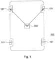
- Figure 1 illustrates a vehicle 100, for example a car or lorry, having four wheels 101, where two wheels are located in the vehicles forward position in a near side and off side position respectively, where the near side wheel is designated the first wheel and the off side wheel is designated the second wheel. Similarly, two additional wheels are located in the vehicles aft position in near side and off side positions respectively, as is typical for a conventional car configuration. However, as would be appreciated by a person skilled in the art, the vehicle may have any number of wheels.
- each in-wheel electric motor acts as a drive source for each respective wheel.
- each in-wheel electric motor acts as a drive source for each respective wheel.
- the current embodiment describes a vehicle having an in-wheel electric motor associated with each of the two front wheels 101, as would be appreciated by a person skilled in the art other in-wheel electric motor configurations may be adopted. For example, for a four wheeled vehicle all the wheels may have associated in-wheel motors or alternately only the rear two wheels may have associated in-wheel motors.
- each in-wheel electric motor is a central controller 102, where the function of the central controller 102 is described in detail below.
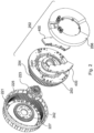
- the in-wheel electric motor includes a stator 252 comprising a heat sink 253, multiple coils 254, two control devices 400 mounted on the heat sink 253 on a rear portion of the stator for driving the coils, and an annular capacitor, otherwise known as a DC link capacitor, mounted on the stator within the inner radius of the control devices 400.
- the coils 254 are formed on stator tooth laminations to form coil windings.
- a stator cover 256 is mounted on the rear portion of the stator 252, enclosing the control devices 400 to form the stator 252, which may then be fixed to a vehicle and does not rotate relative to the vehicle during use.
- Each control device 400 includes two inverters 410 and control logic 420, which in the present embodiment includes a processor, for controlling the operation of the inverters 410, which is schematically represented in Figure 4 .
- the in-wheel electric motor includes two control devices, where each control device includes control logic, in other words a controller, for controlling the operation of an inverter, any configuration of control logic and inverter combination may be used, including placing the control logic and/or inverters remote to the electric motor.
- the annular capacitor is coupled across the inverters 410 and the electric motor's DC power source for reducing voltage ripple on the electric motor's power supply line, otherwise known as the DC busbar, and for reducing voltage overshoots during operation of the electric motor.
- the capacitor is mounted adjacent to the control devices 400. Accordingly, current flow to the electric motor is via the DC busbar, where the electric motor acts as an electrical load to the DC power source with the DC power source's voltage being placed across the DC busbar.
- a current sensor is used to measure the DC busbar line current to the electric motor.
- a rotor 240 comprises a front portion 220 and a cylindrical portion 221 forming a cover, which substantially surrounds the stator 252.
- the rotor includes a plurality of permanent magnets 242 arranged around the inside of the cylindrical portion 221.
- 32 magnet pairs are mounted on the inside of the cylindrical portion 221.
- any number of magnet pairs may be used.
- the magnets are in close proximity to the coil windings on the stator 252 so that magnetic fields generated by the coils interact with the magnets 242 arranged around the inside of the cylindrical portion 221 of the rotor 240 to cause the rotor 240 to rotate.
- the permanent magnets 242 are utilized to generate a drive torque for driving the electric motor, the permanent magnets are typically called drive magnets.
- the rotor 240 is attached to the stator 252 by a bearing block 223.
- the bearing block 223 can be a standard bearing block as would be used in a vehicle to which this motor assembly is to be fitted.
- the bearing block comprises two parts, a first part fixed to the stator and a second part fixed to the rotor.
- the bearing block is fixed to a central portion 253 of the wall of the stator 252 and also to a central portion 225 of the housing wall 220 of the rotor 240.
- the rotor 240 is thus rotationally fixed to the vehicle with which it is to be used via the bearing block 223 at the central portion 225 of the rotor 240.
- the wheel bolts may be fitted through the central portion 225 of the rotor through into the bearing block itself.
- FIG 3 shows an exploded view of the same motor assembly illustrated in Figure 2 from the opposite side.
- the rotor 240 comprises the outer rotor wall 220 and circumferential wall 221 within which magnets 242 are circumferentially arranged.
- the stator 252 is connected to the rotor 240 via the bearing block at the central portions of the rotor and stator walls.
- a V shaped seal is provided between the circumferential wall 221 of the rotor and the outer edge of the stator.
- the rotor also includes a set of magnets 227 for position sensing, otherwise known as commutation magnets, which in conjunction with sensors mounted on the stator allows for a rotor flux angle to be estimated.
- the rotor flux angle defines the positional relationship of the drive magnets to the coil windings.
- the rotor may include a ring of magnetic material that has multiple poles that act as a set of separate magnets.
- each drive magnet has an associated commutation magnet, where the rotor flux angle is derived from the flux angle associated with the set of commutation magnets by calibrating the measured commutation magnet flux angle.
- the set of commutation magnets has the same number of magnets or magnet pole pairs as the set of drive magnet pairs, where the commutation magnets and associated drive magnets are approximately radially aligned with each other. Accordingly, for the purposes of the present embodiment the set of commutation magnets has 32 magnet pairs, where each magnet pair is approximately radially aligned with a respective drive magnet pair.
- a sensor which in this embodiment is a Hall sensor, is mounted on the stator.
- the sensor is positioned so that as the rotor rotates each of the commutation magnets that form the commutation magnet ring respectively rotates past the sensor.
- the commutation magnets correspondingly rotate past the sensor with the Hall sensor outputting an AC voltage signal, where the sensor outputs a complete voltage cycle of 360 electrical degrees for each magnet pair that passes the sensor, where the AC voltage signal output by the Hall sensor can be used for both rotor position detection and for determining rotor velocity ( ⁇ ).
- the senor includes an associated second sensor placed 90 electrical degrees displaced from the first sensor.
- the electric motor includes four coil sets with each coil set having three coil sub-sets that are coupled in a wye configuration to form a three phase sub-motor, resulting in the motor having four three phase sub-motors.
- the operation of the respective sub-motors is controlled via one of the two control devices 400, as described below.
- the present embodiment describes an electric motor having four coil sets (i.e. four sub motors) the motor may equally have one or more coil sets with associated control devices.
- the motor includes eight coil sets 60 with each coil set having three coil sub-sets that are coupled in a wye configuration to form a three phase sub-motor, resulting in the motor having eight three phase sub-motors.
- each coil set may have any number of coil sub-sets, thereby allowing each sub-motor to have two or more phases.
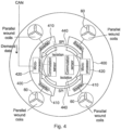
- Figure 4 illustrates the connections between the respective coil sets 60 and the control devices 400, where a respective coil set 60 is connected to a respective three phase inverter 410 included on a control device 400 for controlling current flow within the respective coil sets.
- a three phase inverter contains six switches, where a three phase alternating voltage may be generated by the controlled operation of the six switches.
- the number of switches will depend upon the number of voltage phases to be applied to the respective sub motors, where the sub motors can be constructed to have any number of phases.
- control devices 400 are of a modular construction.
- Figure 5 illustrates an exploded view of a preferred embodiment, where each control device 400, otherwise known as a power module, includes a power printed circuit board 500 in which are mounted two power substrate assemblies 510, a control printed circuit board 520, four power source busbars 530 for connecting to a DC battery, and six phase winding busbars 540 for connecting to respective coil windings.
- Each of the control device components are mounted within a control device housing 550 with the four power source busbars 530 being mounted on an opposite side of the control device housing 550 to the phase winding busbars 540.
- Each power substrate 510 is arranged to be mounted in a respective aperture formed in the power printed circuit board 500.
- the power printed circuit board 500 includes a variety of components that include drivers for the inverter switches formed on the power substrate assemblies 510, where the drivers are typically used to convert control signals into a suitable form to turn the inverter switches on and off.
- the control printed circuit board 520 includes a processor for controlling the operation of the inverter switches. Additionally, each control printed circuit board 520 includes an interface arrangement to allow communication between the respective control devices 400 via a communication bus with one control device 400 being arranged to communicate with a vehicle controller mounted external to the electric motor. The processor 420 on each control device 400 is arranged to handle communication over the interface arrangement.
- the processors 420 on the respective control devices 400 are arranged to control the operation of the inverter switches mounted on the respective power substrates 520 within the control housing 550, thereby allowing each of the electric motor coil sets 60 to be supplied with a three phase voltage supply resulting in the respective coil sub-sets generating a rotating magnetic field.
- each coil set 60 may have one or more coil sub-sets.
- each three phase bridge inverter 410 is arranged to provide pulse width modulation PWM voltage control across the respective coil sub-sets, thereby generating a current flow in the respective coil sub-sets for providing a required torque by the respective sub-motors, where the current flow in the respective coil sub-sets is known as phase current.
- PWM control works by using the motor inductance to average out an applied pulse voltage to drive the required current into the motor coils.
- PWM control an applied voltage is switched across the motor windings. During the period when voltage is switched across the motor coils, the current rises in the motor coils at a rate dictated by their inductance and the applied voltage.
- the PWM voltage control is switched off before the current has increased beyond a required value, thereby allowing precise control of the phase current within the coil sub-sets to be achieved.
- the three phase bridge inverter 410 switches are arranged to apply a single voltage phase across each of the coil sub-sets.
- the plurality of switches are arranged to apply an alternating voltage across the respective coil sub-sets.
- the voltage envelope and phase angle of the electrical signals is determined by the modulating voltage pulses.
- Figure 6 illustrates an example of phase currents in a coil set having three coil sub-sets, otherwise known as a three phase motor configuration, showing three phases.
- the inverter switches can include semiconductor devices such as MOSFETs or IGBTs.
- the switches comprise IGBTs.
- any suitable known switching circuit can be employed for controlling the current.
- the six switches are configured as three parallel sets of two switches, where each pair of switches is placed in series and form a leg of the three phase bridge circuit, with a fly-back diode, otherwise known as a reverse diode, coupled in anti-parallel across each switch.
- a single phase inverter will have two pairs of switches arranged in series to form two legs 600 of an inverter.
- each of the inverter legs 600 are electrically coupled between a pair of power source busbars.
- PWM switching is used to apply an alternating voltage to the electric motors coil windings, where the rotor speed is dependent upon the amplitude of the voltage applied across the coil windings.
- the torque applied to the rotor results from phase current within the coil windings, where motor torque is proportional to the amplitude of the phase current.
- T ⁇ I 2 rotor phase current amplitude
- a hazard yaw condition is prevented by ensuring that the power differential between the power being applied to the transversely mounted wheels is below a threshold value.
- Empirical driver response studies indicate that power asymmetry values greater than 30 kW/tonne typically result in a hazardous induced yaw condition occurring that a driver of a vehicle may find difficult to control. Accordingly, in a preferred embodiment if the power differential between the power being applied to the first wheel and the second wheel is greater than 30 kW/tonne of vehicle weight, a controller is arranged to reduce the power differential.
- other power asymmetry threshold values may be used to indicate a hazard induced yaw condition.
- the power differential threshold value used for identifying a hazard induced yaw condition for example 30kW/tonne, is applicable across the vehicle's speed range and is not speed dependent. Accordingly, unlike torque asymmetry limits the same power differential threshold value can be used for identifying a hazard induced yaw condition irrespective of vehicle speed.
- the following described control system is arranged to prevent a hazard induced yaw condition occurring while also maintaining some level of drive to one or more of the vehicles wheels.
- control devices 400 incorporated within electric motors that are arranged to provide drive to the transversely mounted wheels, are arranged to communicate torque and/or power information being applied to a respective wheel of the vehicle to each other, thereby allowing the respective control devices to ensure that the power differential between transversely mounted wheels be maintained below a threshold value, as described above.
- the torque and/or power information is communicated to allow each respective control device determine the torque and/or power that is being applied to a transversely mounted wheel and consequently allow each control device within the respective electric motors to determine whether the power being applied to the transversely mounted wheels results in a power differential threshold being exceeded.
- the first controller is arranged to estimate a plurality of possible power values for the power applied to the second wheel by the second electric motor.
- the first controller is arranged to estimate a first power value for the power applied to the second wheel by the second electric motor when the second electric motor is placed in a first motor configuration and estimate a second power value for the power applied to the second wheel by the second electric motor when the second electric motor is placed in a second motor configuration, thereby estimating possible power values for the power applied to the second wheel by the second electric motor for a plurality of different scenarios.
- the first controller Upon the first controller estimating the plurality of different possible power values that could be applied by the second electric motor to the second wheel the first controller is arranged to determine a first power differential between the power being applied to the first wheel by the first electric motor and the first estimated power value and a second power differential between the power being applied to the first wheel by the first electric motor and the second estimated power value. If the first controller determines that if either the first power differential or the second power differential is greater than a predetermined value the first controller is arranged to adjust the torque generated by the first electric motor to ensure that the maximum possible power differential would not result in yaw safety limits being exceeded. If the first controller determines that both the first power differential and the second power differential are less than a predetermined value the first controller is arranged to maintain the torque generated by the first electric motor
- each control device within the respective in-wheel electric motors are arranged to determine the power, for example mechanical power, being applied to the respective wheel for which the respective in-wheel electric motor is acting as a drive source.
- the respective control devices are arrange to determine mechanical power, however the power generated by the respective electric motors may be determined by any suitable means, for example electrical power.
- Mechanical power is estimated using phase current measurements to estimate the torque generated by the respective in-wheel electric motors.
- the value of torque (T) is then combined with rotational velocity ( ⁇ ) of the respective rotors to provide an estimate of motor mechanical power, namely a product of torque and rotational velocity (T ⁇ ).
- Figure 7 illustrates a preferred embodiment of a control system for use in the vehicle illustrated in Figure 1 for avoiding a yaw hazard condition occurring following a fault associated with one of the electric motors causing loss of communication between both electric motors.
- the vehicle includes two in-wheel electric motors 710 that are arranged to drive the first wheel (i.e. the front near side wheel) and the second wheel (i.e. the front offside wheel) respectively with a main controller 102 arranged to provide torque values to each of the in-wheel electric motors 710 for providing a drive torque, where the torque values provided by the main controller 102 to the respective electric motors 710 are typically based on driver input, for example the position of a throttle pedal.
- control devices associated with both in-wheel electric motors include first sensing means 720, first power monitoring means 730 and a software drive disable function 740.
- the first sensing means 720 is arranged to determine the mechanical power being developed by the respective in-wheel motor (P A ) from motor phase current and speed, where each control device is arranged to communicate the determined mechanical power to the other electric motor.
- the first power monitoring means 730 associated with each in-wheel electric motor is arranged to compare the mechanical power being developed by its own motor (e.g. P A1 ) with that of the other motor (e.g. P A2 ), and sends a software disable request to the software drive disable function 740 should the asymmetric power exceed the predetermined threshold value P ASY (for example, greater than 30 kW/tonne).
- a torque reduction request typically communicated via the main controller 102, may be issued to reduce the power differential between the two in-wheel electric motors. If, however, a dynamic control function within main controller 102 indicates that an advanced stability control features (e.g. torque vectoring) has been selected that requires power asymmetries of greater than the designated threshold value the above power differential threshold may be adjusted to a different value.
- the stability control system is arranged not to reduce the identified power asymmetry, for example the dynamic control function may over ride the software disable request or set a different power asymmetry threshold value.
- the software drive disable function 740 within the motor is arranged to disable the motor drive PWM waveforms in response to receipt of a software disable request received from the first power monitoring means 730.
- both in-wheel electric motors 710 include a hardware drive disable function 770.
- the hardware drive disable function 770 is independent of the software disable function 740, where the motor will be disabled if either the hardware drive disable function 770 or the software disable function 740 is active
- a control device within the electric motor that fails to receive the power information is arranged to make a power value determination for the other electric motor. Due to the loss of communication from the other electric motor and without knowledge as to which motor configuration the other electric motor may have been placed in, for example if the other electric motor has experienced a fault it may be in one of a plurality of disabled modes, the electric motor is arranged to make a power value determination for the other electric motor for a plurality of different motor configurations. For example:
- Figure 8 Illustrations of drag torques for these different motor configurations are shown in Figure 8 .
- the torque values can be converted to power by multiply them by speed, as illustrated in Figure 9 .
- line A corresponds to the electric motor being disconnected
- line B corresponds to the electric motor being in a short circuit configuration
- line C corresponds to the electric motor being in an open circuit configuration.
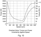
- Figure 10 illustrates the variations in possible torque and power values for the other electric motor, which corresponds to the maximum difference between any two lines in Figures 8 and 9 , where line D corresponds to uncertainty in power and line E corresponds to uncertainty in torque.
- the electric motor Upon the electric motor determining power values for the other electric motor when in a plurality of different configurations, the electric motor compares the power it is generating against each of the different motor configurations the other electric motor may have been placed in.
- the electric motor is arranged to calculate the power differential assuming that the other motor is in a short circuit configuration, a disabled mode and in a freewheeling mode. If either of these configurations were to result in the power differential exceeding 30 kW/tonne the electric motor would take action to reduce the power differential.
- electric motor may notify the main controller 102 of the need to adjust the torque value being issued to the electric motor or the electric motor may initiate a safe state, where both electric motors are placed in a disabled state.
- the electric motor can continue to operate under the control of the main controller 102 without any change in power, thereby allowing the vehicle to operate with potentially one of the electric motors being non-operational and without a yaw hazard condition occurring.
- the main controller 102 may provide the electric motor that has lost communication with the other motor with any torque values that would not result in any of the different possible power differentials exceeding a yaw hazard condition threshold value.
Landscapes
- Engineering & Computer Science (AREA)
- Transportation (AREA)
- Mechanical Engineering (AREA)
- Power Engineering (AREA)
- Life Sciences & Earth Sciences (AREA)
- Sustainable Development (AREA)
- Sustainable Energy (AREA)
- Chemical & Material Sciences (AREA)
- Combustion & Propulsion (AREA)
- Electric Propulsion And Braking For Vehicles (AREA)
Description
- The present invention relates to a control system, in particular a control system for a vehicle.
- With increased interest being placed in environmentally friendly vehicles there has, perhaps unsurprisingly, been a corresponding increase in interest in the use of electric vehicles.
- Although most commercially available electric vehicles utilise a central electric motor that is used to drive two or more of the vehicles wheels, an alternative solution that is gaining increased popularity utilises in-wheel electric motors, where individual electric motors are used to drive the respective wheels of a vehicle, thereby allowing torque delivery to each wheel to be independently controlled. The fast response characteristics of an electric motor together with independent torque control to the wheels of a vehicle allow in-wheel electric motors to be used to improve vehicle stability complementing or replacing additional vehicle stability control mechanisms. For example, the independent torque control of in-wheel electric motors can be used to provide both traction control and vehicle dynamic control.
- However, for vehicles having a plurality of wheels driven by their own independent drive source, if torque delivery to each road wheel is applied incorrectly any associated torque asymmetry may cause the hazard induced yaw.
- Consequently, a vehicle having a drive system, in which torque is independently delivered to each wheel of the vehicle, preferably includes a monitoring system that monitors the torque being applied to each respective wheel, where the monitoring system takes corrective action should the torque asymmetry reach an unacceptable level.
- If, however, the monitoring system fails to receive torque information associated with one of the wheels, to prevent the possibility of a hazard induced yaw the monitoring system will typically place the drive system in a safe state by disabling the whole drive system, thereby disabling the vehicle.
-
WO2017/051308 describes a control system for a vehicle having a first wheel arranged to be driven by a first drive source and a second wheel arranged to be driven by a second drive source, wherein the first wheel and the second wheel are transversely located on the vehicle, the control system comprising a controller and a monitoring device, wherein the monitoring device is arranged to monitor the power differential between the power being applied to the first wheel by the first drive source and the power being applied to the second wheel by the second drive source, wherein upon a determination that the power differential between the power being applied to the first wheel and the second wheel is greater than a predetermined value, the controller is arranged to reduce the power differential. - In accordance with an aspect of the present invention there is provided a control system and method according to the accompanying claims.
-
EP 2 676 830 describes a torque distribution apparatus includes a instructed torque acquiring unit that acquires instructed torque input; an efficiency map acquiring unit that acquires a motor efficiency map (104) that corresponds to equipped motors; a vehicular speed detecting unit that detects vehicular speed of a vehicle; a drive wheel rotational speed detecting unit that detects drive wheel rotational speed of the drive wheels; a slip rate calculating unit that based on the vehicular speed and the drive wheel rotational speed, calculates slip rate at the drive wheels; a calculating unit that based on the slip rate, creates an efficiency variation expression that indicates efficiency values on a performance curve that indicates relations between the drive wheel rotational speed and torque, and calculates a torque that optimizes efficiency from the efficiency variation expression on the performance curve; a distributing unit that based on the slip rate, the instructed torque and the torque optimizing efficiency, calculates a torque distribution value for each of the motors such that the total efficiency is maximized; and a control unit that based on the calculated torque distribution values, controls torque distribution to each of the motors. - For a vehicle configuration where transversely mounted wheels are independently driven by separate electric motors, the present invention as claimed provides the advantage of, upon loss of communication of one electric motor with another electric motor, allowing the vehicle to be powered by a single motor without exceeding yaw safety limits. A determination is made as to whether the power being generated by the electric motor, for which communication with has been lost, is below a threshold value. If a determination is made that the power generated by the other electric motor is below the threshold value the power generated by the electric motor that is no longer receiving communication from the other electric motor may maintain the torque generated by the electric motor, thereby allowing the vehicle to be powered by a single motor without exceeding yaw safety limits.
- The present invention will now be described, by way of example, with reference to the accompanying drawings, in which:
-
Figure 1 illustrates a vehicle according to an embodiment of the present invention; -
Figure 2 illustrates an exploded view of an electric motor as used in an embodiment of the present invention; -
Figure 3 illustrates an exploded view of the electric motor shown inFigure 2 from an alternative angle; -
Figure 4 illustrates an electric motor according to an embodiment of the present invention; -
Figure 5 illustrates an exploded view of a control device according to an embodiment of the present invention; -
Figure 6 illustrates phase currents in a three phase electric motor; -
Figure 7 illustrates a stability control system according to an embodiment of the present invention; -
Figure 8 illustrates drag torque for a plurality of motor configurations; -
Figure 9 illustrates drag power for a plurality of motor configurations; -
Figure 10 illustrates drag power and drag torque uncertainty values for different motor configurations. - The embodiment of the invention described is for a control system for preventing, upon such as loss of communication between two electric motors that are independently driving transversely mounted wheels on a vehicle, a hazard induced yaw condition. The control system is for a vehicle having a first wheel arranged to be driven by a first electric motor and a second wheel arranged to be driven by a second electric motor, wherein the first wheel and the second wheel are transversely located on the vehicle relative to each other. The control system includes a first controller associated with the first electric motor and a second controller associated with the second electric motor. Upon the first controller failing to receive power or torque information generated by the second electric motor the first controller estimates a first power value for the power applied to the second wheel by the second electric motor when the second electric motor is placed in a first motor configuration and estimates a second power value for the power applied to the second wheel by the second electric motor when the second electric motor is placed in a second motor configuration, thereby estimating possible power values for the power applied to the second wheel by the second electric motor for a plurality of different scenarios. Upon the first controller estimating the plurality of different possible power values which could be applied by the second electric motor to the second wheel the first controller is arranged to determine a first power differential between the power being applied to the first wheel by the first electric motor and the first estimated power value and a second power differential between the power being applied to the first wheel by the first electric motor and the second estimated power value. If the first controller determines that if either the first power differential or the second power differential is greater than a predetermined value the first controller is arranged to adjust the torque generated by the first electric motor to ensure that the maximum possible power differential would not result in yaw safety limits being exceeded. If the first controller determines that both the first power differential and the second power differential are less than a predetermined value the first controller is arranged to maintain the torque generated by the first electric motor
- For the purposes of the present embodiment the electric motors are for use in a wheel of a vehicle, however the electric motors may be located anywhere within the vehicle. The motors are of the type having a set of coils being part of a stator for attachment to a vehicle, radially surrounded by a rotor carrying a set of magnets for attachment to a wheel. In addition, some of the aspects of the invention are applicable to an arrangement having the rotor centrally mounted within radially surrounding coils. As would be appreciated by a person skilled in the art, the present invention is applicable for use with other types of electric motors or drive systems.
-
Figure 1 illustrates avehicle 100, for example a car or lorry, having fourwheels 101, where two wheels are located in the vehicles forward position in a near side and off side position respectively, where the near side wheel is designated the first wheel and the off side wheel is designated the second wheel. Similarly, two additional wheels are located in the vehicles aft position in near side and off side positions respectively, as is typical for a conventional car configuration. However, as would be appreciated by a person skilled in the art, the vehicle may have any number of wheels. - Incorporated within each of the two
front wheels 101 is an in-wheel electric motor, as described in detail below, where each in-wheel electric motor acts as a drive source for each respective wheel. However, although the current embodiment describes a vehicle having an in-wheel electric motor associated with each of the twofront wheels 101, as would be appreciated by a person skilled in the art other in-wheel electric motor configurations may be adopted. For example, for a four wheeled vehicle all the wheels may have associated in-wheel motors or alternately only the rear two wheels may have associated in-wheel motors. - Coupled to each in-wheel electric motor is a
central controller 102, where the function of thecentral controller 102 is described in detail below. - For the purposes of the present embodiment, as illustrated in
Figure 2 andFigure 3 , the in-wheel electric motor includes astator 252 comprising aheat sink 253,multiple coils 254, twocontrol devices 400 mounted on theheat sink 253 on a rear portion of the stator for driving the coils, and an annular capacitor, otherwise known as a DC link capacitor, mounted on the stator within the inner radius of thecontrol devices 400. Thecoils 254 are formed on stator tooth laminations to form coil windings. Astator cover 256 is mounted on the rear portion of thestator 252, enclosing thecontrol devices 400 to form thestator 252, which may then be fixed to a vehicle and does not rotate relative to the vehicle during use. - Each
control device 400 includes twoinverters 410 andcontrol logic 420, which in the present embodiment includes a processor, for controlling the operation of theinverters 410, which is schematically represented inFigure 4 . Although for the purposes of the present embodiment the in-wheel electric motor includes two control devices, where each control device includes control logic, in other words a controller, for controlling the operation of an inverter, any configuration of control logic and inverter combination may be used, including placing the control logic and/or inverters remote to the electric motor. - The annular capacitor is coupled across the
inverters 410 and the electric motor's DC power source for reducing voltage ripple on the electric motor's power supply line, otherwise known as the DC busbar, and for reducing voltage overshoots during operation of the electric motor. For reduced inductance the capacitor is mounted adjacent to thecontrol devices 400. Accordingly, current flow to the electric motor is via the DC busbar, where the electric motor acts as an electrical load to the DC power source with the DC power source's voltage being placed across the DC busbar. As described below, a current sensor is used to measure the DC busbar line current to the electric motor. - A
rotor 240 comprises afront portion 220 and acylindrical portion 221 forming a cover, which substantially surrounds thestator 252. The rotor includes a plurality ofpermanent magnets 242 arranged around the inside of thecylindrical portion 221. For the purposes of the present embodiment 32 magnet pairs are mounted on the inside of thecylindrical portion 221. However, any number of magnet pairs may be used. - The magnets are in close proximity to the coil windings on the
stator 252 so that magnetic fields generated by the coils interact with themagnets 242 arranged around the inside of thecylindrical portion 221 of therotor 240 to cause therotor 240 to rotate. As thepermanent magnets 242 are utilized to generate a drive torque for driving the electric motor, the permanent magnets are typically called drive magnets. - The
rotor 240 is attached to thestator 252 by abearing block 223. Thebearing block 223 can be a standard bearing block as would be used in a vehicle to which this motor assembly is to be fitted. The bearing block comprises two parts, a first part fixed to the stator and a second part fixed to the rotor. The bearing block is fixed to acentral portion 253 of the wall of thestator 252 and also to acentral portion 225 of thehousing wall 220 of therotor 240. Therotor 240 is thus rotationally fixed to the vehicle with which it is to be used via thebearing block 223 at thecentral portion 225 of therotor 240. This has an advantage in that a wheel rim and tyre can then be fixed to therotor 240 at thecentral portion 225 using the normal wheel bolts to fix the wheel rim to the central portion of the rotor and consequently firmly onto the rotatable side of thebearing block 223. The wheel bolts may be fitted through thecentral portion 225 of the rotor through into the bearing block itself. With both therotor 240 and the wheel being mounted to the bearing block 223 there is a one to one correspondence between the angle of rotation of the rotor and the wheel. -
Figure 3 shows an exploded view of the same motor assembly illustrated inFigure 2 from the opposite side. Therotor 240 comprises theouter rotor wall 220 andcircumferential wall 221 within whichmagnets 242 are circumferentially arranged. As previously described, thestator 252 is connected to therotor 240 via the bearing block at the central portions of the rotor and stator walls. - A V shaped seal is provided between the
circumferential wall 221 of the rotor and the outer edge of the stator. - The rotor also includes a set of
magnets 227 for position sensing, otherwise known as commutation magnets, which in conjunction with sensors mounted on the stator allows for a rotor flux angle to be estimated. The rotor flux angle defines the positional relationship of the drive magnets to the coil windings. Alternatively, in place of a set of separate magnets the rotor may include a ring of magnetic material that has multiple poles that act as a set of separate magnets. - To allow the commutation magnets to be used to calculate a rotor flux angle, preferably each drive magnet has an associated commutation magnet, where the rotor flux angle is derived from the flux angle associated with the set of commutation magnets by calibrating the measured commutation magnet flux angle. To simplify the correlation between the commutation magnet flux angle and the rotor flux angle, preferably the set of commutation magnets has the same number of magnets or magnet pole pairs as the set of drive magnet pairs, where the commutation magnets and associated drive magnets are approximately radially aligned with each other. Accordingly, for the purposes of the present embodiment the set of commutation magnets has 32 magnet pairs, where each magnet pair is approximately radially aligned with a respective drive magnet pair.
- A sensor, which in this embodiment is a Hall sensor, is mounted on the stator. The sensor is positioned so that as the rotor rotates each of the commutation magnets that form the commutation magnet ring respectively rotates past the sensor.
- As the rotor rotates relative to the stator the commutation magnets correspondingly rotate past the sensor with the Hall sensor outputting an AC voltage signal, where the sensor outputs a complete voltage cycle of 360 electrical degrees for each magnet pair that passes the sensor, where the AC voltage signal output by the Hall sensor can be used for both rotor position detection and for determining rotor velocity (ω).
- For improved position detection, preferably the sensor includes an associated second sensor placed 90 electrical degrees displaced from the first sensor.
- In the present embodiment the electric motor includes four coil sets with each coil set having three coil sub-sets that are coupled in a wye configuration to form a three phase sub-motor, resulting in the motor having four three phase sub-motors. The operation of the respective sub-motors is controlled via one of the two
control devices 400, as described below. However, although the present embodiment describes an electric motor having four coil sets (i.e. four sub motors) the motor may equally have one or more coil sets with associated control devices. In a preferred embodiment the motor includes eight coil sets 60 with each coil set having three coil sub-sets that are coupled in a wye configuration to form a three phase sub-motor, resulting in the motor having eight three phase sub-motors. Similarly, each coil set may have any number of coil sub-sets, thereby allowing each sub-motor to have two or more phases. -
Figure 4 illustrates the connections between the respective coil sets 60 and thecontrol devices 400, where a respective coil set 60 is connected to a respective threephase inverter 410 included on acontrol device 400 for controlling current flow within the respective coil sets. As is well known to a person skilled in the art, a three phase inverter contains six switches, where a three phase alternating voltage may be generated by the controlled operation of the six switches. However, the number of switches will depend upon the number of voltage phases to be applied to the respective sub motors, where the sub motors can be constructed to have any number of phases. - Preferably, the
control devices 400 are of a modular construction.Figure 5 illustrates an exploded view of a preferred embodiment, where eachcontrol device 400, otherwise known as a power module, includes a power printedcircuit board 500 in which are mounted twopower substrate assemblies 510, a control printedcircuit board 520, fourpower source busbars 530 for connecting to a DC battery, and sixphase winding busbars 540 for connecting to respective coil windings. Each of the control device components are mounted within acontrol device housing 550 with the fourpower source busbars 530 being mounted on an opposite side of thecontrol device housing 550 to thephase winding busbars 540. - As stated above, current flow to the electric motor, in other words the line current, is via the respective power source busbars, where the electric motor acts as an electrical load to the DC power source with the DC power source's voltage being placed across the respective power source busbars.
- Each
power substrate 510 is arranged to be mounted in a respective aperture formed in the power printedcircuit board 500. - The power printed
circuit board 500 includes a variety of components that include drivers for the inverter switches formed on thepower substrate assemblies 510, where the drivers are typically used to convert control signals into a suitable form to turn the inverter switches on and off. - The control printed
circuit board 520 includes a processor for controlling the operation of the inverter switches. Additionally, each control printedcircuit board 520 includes an interface arrangement to allow communication between therespective control devices 400 via a communication bus with onecontrol device 400 being arranged to communicate with a vehicle controller mounted external to the electric motor. Theprocessor 420 on eachcontrol device 400 is arranged to handle communication over the interface arrangement. - As stated above, the
processors 420 on therespective control devices 400 are arranged to control the operation of the inverter switches mounted on therespective power substrates 520 within thecontrol housing 550, thereby allowing each of the electric motor coil sets 60 to be supplied with a three phase voltage supply resulting in the respective coil sub-sets generating a rotating magnetic field. As stated above, although the present embodiment describes each coil set 60 as having three coil sub-sets the present invention is not limited by this and it would be appreciated that each coil set 60 may have one or more coil sub-sets. - Under the control of the
respective processors 420, each threephase bridge inverter 410 is arranged to provide pulse width modulation PWM voltage control across the respective coil sub-sets, thereby generating a current flow in the respective coil sub-sets for providing a required torque by the respective sub-motors, where the current flow in the respective coil sub-sets is known as phase current. - PWM control works by using the motor inductance to average out an applied pulse voltage to drive the required current into the motor coils. Using PWM control an applied voltage is switched across the motor windings. During the period when voltage is switched across the motor coils, the current rises in the motor coils at a rate dictated by their inductance and the applied voltage. The PWM voltage control is switched off before the current has increased beyond a required value, thereby allowing precise control of the phase current within the coil sub-sets to be achieved.
- For a given coil set 60 the three
phase bridge inverter 410 switches are arranged to apply a single voltage phase across each of the coil sub-sets. - Using PWM switching, the plurality of switches are arranged to apply an alternating voltage across the respective coil sub-sets. The voltage envelope and phase angle of the electrical signals is determined by the modulating voltage pulses.
Figure 6 illustrates an example of phase currents in a coil set having three coil sub-sets, otherwise known as a three phase motor configuration, showing three phases. - The inverter switches can include semiconductor devices such as MOSFETs or IGBTs. In the present example, the switches comprise IGBTs. However, any suitable known switching circuit can be employed for controlling the current. For a three phase inverter having six switches configured to drive a three phase electric motor, the six switches are configured as three parallel sets of two switches, where each pair of switches is placed in series and form a leg of the three phase bridge circuit, with a fly-back diode, otherwise known as a reverse diode, coupled in anti-parallel across each switch. A single phase inverter will have two pairs of switches arranged in series to form two
legs 600 of an inverter. - As stated above, each of the
inverter legs 600 are electrically coupled between a pair of power source busbars. - As stated above, PWM switching is used to apply an alternating voltage to the electric motors coil windings, where the rotor speed is dependent upon the amplitude of the voltage applied across the coil windings. The torque applied to the rotor results from phase current within the coil windings, where motor torque is proportional to the amplitude of the phase current. In other words:

A control system for preventing a hazard induced yaw condition occurring following a loss of communication between two drive sources arranged to provide drive to two transversely mounted wheels respectively for the vehicle illustrated inFigure 1 , while also allowing the electric motor drive system to provide a drive torque, will now be described. This provides the advantage of allowing a vehicle to continue operation despite a fault occurring with an electric motor or a communication link between two electric motors. - Under normal circumstances, for a vehicle drive system having transversely mounted wheels that are independent driven by separate drive sources, a hazard yaw condition is prevented by ensuring that the power differential between the power being applied to the transversely mounted wheels is below a threshold value. Empirical driver response studies indicate that power asymmetry values greater than 30 kW/tonne typically result in a hazardous induced yaw condition occurring that a driver of a vehicle may find difficult to control. Accordingly, in a preferred embodiment if the power differential between the power being applied to the first wheel and the second wheel is greater than 30 kW/tonne of vehicle weight, a controller is arranged to reduce the power differential. However, other power asymmetry threshold values may be used to indicate a hazard induced yaw condition.
- As the derivation of power includes a speed term the power differential threshold value used for identifying a hazard induced yaw condition, for example 30kW/tonne, is applicable across the vehicle's speed range and is not speed dependent. Accordingly, unlike torque asymmetry limits the same power differential threshold value can be used for identifying a hazard induced yaw condition irrespective of vehicle speed.
- If, however, communication is lost with one of the electric motors, for example due to a fault with one of the electric motors or a fault with a communication link to an electric motor, the following described control system is arranged to prevent a hazard induced yaw condition occurring while also maintaining some level of drive to one or more of the vehicles wheels.
- To improve vehicle safety for a vehicle having independently driven transversely mounted wheels,
control devices 400, incorporated within electric motors that are arranged to provide drive to the transversely mounted wheels, are arranged to communicate torque and/or power information being applied to a respective wheel of the vehicle to each other, thereby allowing the respective control devices to ensure that the power differential between transversely mounted wheels be maintained below a threshold value, as described above. The torque and/or power information is communicated to allow each respective control device determine the torque and/or power that is being applied to a transversely mounted wheel and consequently allow each control device within the respective electric motors to determine whether the power being applied to the transversely mounted wheels results in a power differential threshold being exceeded. - However, upon a
control device 400, otherwise known as the first controller, incorporated within the electric motor arranged to provide drive to the first wheel failing to receive power or torque information generated by the electric motor arranged to provide torque to the second wheel, the first controller is arranged to estimate a plurality of possible power values for the power applied to the second wheel by the second electric motor. In particular, the first controller is arranged to estimate a first power value for the power applied to the second wheel by the second electric motor when the second electric motor is placed in a first motor configuration and estimate a second power value for the power applied to the second wheel by the second electric motor when the second electric motor is placed in a second motor configuration, thereby estimating possible power values for the power applied to the second wheel by the second electric motor for a plurality of different scenarios. - Upon the first controller estimating the plurality of different possible power values that could be applied by the second electric motor to the second wheel the first controller is arranged to determine a first power differential between the power being applied to the first wheel by the first electric motor and the first estimated power value and a second power differential between the power being applied to the first wheel by the first electric motor and the second estimated power value. If the first controller determines that if either the first power differential or the second power differential is greater than a predetermined value the first controller is arranged to adjust the torque generated by the first electric motor to ensure that the maximum possible power differential would not result in yaw safety limits being exceeded. If the first controller determines that both the first power differential and the second power differential are less than a predetermined value the first controller is arranged to maintain the torque generated by the first electric motor
- Preferably, each control device within the respective in-wheel electric motors are arranged to determine the power, for example mechanical power, being applied to the respective wheel for which the respective in-wheel electric motor is acting as a drive source.
- For the purposes of the present embodiment the respective control devices are arrange to determine mechanical power, however the power generated by the respective electric motors may be determined by any suitable means, for example electrical power.
- Mechanical power is estimated using phase current measurements to estimate the torque generated by the respective in-wheel electric motors. The value of torque (T) is then combined with rotational velocity (ω) of the respective rotors to provide an estimate of motor mechanical power, namely a product of torque and rotational velocity (T ω).
-
Figure 7 illustrates a preferred embodiment of a control system for use in the vehicle illustrated inFigure 1 for avoiding a yaw hazard condition occurring following a fault associated with one of the electric motors causing loss of communication between both electric motors. - The vehicle includes two in-wheel
electric motors 710 that are arranged to drive the first wheel (i.e. the front near side wheel) and the second wheel (i.e. the front offside wheel) respectively with amain controller 102 arranged to provide torque values to each of the in-wheelelectric motors 710 for providing a drive torque, where the torque values provided by themain controller 102 to the respectiveelectric motors 710 are typically based on driver input, for example the position of a throttle pedal. - To support mechanical power estimation functionality, the control devices associated with both in-wheel electric motors include first sensing means 720, first power monitoring means 730 and a software drive disable
function 740. - The first sensing means 720 is arranged to determine the mechanical power being developed by the respective in-wheel motor (PA) from motor phase current and speed, where each control device is arranged to communicate the determined mechanical power to the other electric motor.
- Under normal circumstances, where each electric motor is receiving power information from the other electric motor, the first power monitoring means 730 associated with each in-wheel electric motor is arranged to compare the mechanical power being developed by its own motor (e.g. PA1) with that of the other motor (e.g. PA2), and sends a software disable request to the software drive disable
function 740 should the asymmetric power exceed the predetermined threshold value PASY (for example, greater than 30 kW/tonne). Alternatively a torque reduction request, typically communicated via themain controller 102, may be issued to reduce the power differential between the two in-wheel electric motors. If, however, a dynamic control function withinmain controller 102 indicates that an advanced stability control features (e.g. torque vectoring) has been selected that requires power asymmetries of greater than the designated threshold value the above power differential threshold may be adjusted to a different value. - As such, if the dynamic control function identifies that the vehicle's stability control requires power asymmetries of greater than the designated threshold value to achieve required handling characteristics, the stability control system is arranged not to reduce the identified power asymmetry, for example the dynamic control function may over ride the software disable request or set a different power asymmetry threshold value.
- The software drive disable
function 740 within the motor is arranged to disable the motor drive PWM waveforms in response to receipt of a software disable request received from the first power monitoring means 730. - Additionally, the both in-wheel
electric motors 710 include a hardware drive disablefunction 770. - The hardware drive disable
function 770 is independent of the software disablefunction 740, where the motor will be disabled if either the hardware drive disablefunction 770 or the software disablefunction 740 is active - However, in a situation where one of the electric motors fails to receive power information from the other electric motor, for example this may occur due a failure of the communication link between the two electric motors or as a result of a failure of one of the electric motors, a control device within the electric motor that fails to receive the power information is arranged to make a power value determination for the other electric motor. Due to the loss of communication from the other electric motor and without knowledge as to which motor configuration the other electric motor may have been placed in, for example if the other electric motor has experienced a fault it may be in one of a plurality of disabled modes, the electric motor is arranged to make a power value determination for the other electric motor for a plurality of different motor configurations. For example:
- 1) A motor configuration where the voltage supply to the other electric motor is disconnected. In this motor configuration the electric motor goes open circuit, where the traction voltage of the electric motor will increase with speed. However, the electric motor will not develop any drag.
- 2) A motor configuration where the coil windings for the other electric motor are shorted together, for example either the low or high side inverter switches are closed. In this configuration the drag torque is highest at lower rotational speeds.
- 3) A motor configuration where the coil windings of the other electric motors are placed in an open circuit configuration to allow current generated by the electric motor to flow onto a power source busbar arranged to provide the voltage supply to the electric motor.
- Illustrations of drag torques for these different motor configurations are shown in
Figure 8 . As stated above the torque values can be converted to power by multiply them by speed, as illustrated inFigure 9 . For the purposes of bothFigures 8 and 9 , line A corresponds to the electric motor being disconnected, line B corresponds to the electric motor being in a short circuit configuration, line C corresponds to the electric motor being in an open circuit configuration. Based on these torque and power values,Figure 10 illustrates the variations in possible torque and power values for the other electric motor, which corresponds to the maximum difference between any two lines inFigures 8 and 9 , where line D corresponds to uncertainty in power and line E corresponds to uncertainty in torque. - Upon the electric motor determining power values for the other electric motor when in a plurality of different configurations, the electric motor compares the power it is generating against each of the different motor configurations the other electric motor may have been placed in. In other words, for the purposes of the present embodiment the electric motor is arranged to calculate the power differential assuming that the other motor is in a short circuit configuration, a disabled mode and in a freewheeling mode. If either of these configurations were to result in the power differential exceeding 30 kW/tonne the electric motor would take action to reduce the power differential. For example, electric motor may notify the
main controller 102 of the need to adjust the torque value being issued to the electric motor or the electric motor may initiate a safe state, where both electric motors are placed in a disabled state. - If, however, a determination is made that the power differential for all possible motor configurations that the other electric motor may be placed in would be below the yaw hazard condition threshold the electric motor can continue to operate under the control of the
main controller 102 without any change in power, thereby allowing the vehicle to operate with potentially one of the electric motors being non-operational and without a yaw hazard condition occurring. Similarly, if a determination is made that the power differential for all possible motor configurations that the other electric motor may be placed in would be below the yaw hazard condition threshold, themain controller 102 may provide the electric motor that has lost communication with the other motor with any torque values that would not result in any of the different possible power differentials exceeding a yaw hazard condition threshold value.
Claims (2)
- A control system for a vehicle (100) having a first wheel (101) arranged to be driven by a first electric motor (710) and a second wheel (101) arranged to be driven by a second electric motor (710), wherein the first wheel and the second wheel are transversely located on the vehicle relative to each other, the control system comprising a first controller associated with the first electric motor and a second controller associated with the second electric motor, wherein the first controller includes means for estimating a first power value for the power applied to the second wheel by the second electric motor when the second electric motor is placed in a first motor configuration and means for estimating a second power value for the power applied to the second wheel by the second electric motor when the second electric motor is placed in a second motor configuration wherein the first motor configuration and the second motor configuration correspond each to one of the following situations:
the second electric motor being disconnected from a voltage supply or coil windings of the second electric motor being placed in a short circuit configuration or coil windings of the second electric motor being place in an open circuit configuration to allow current generated by the second electric motor to flow onto a power source busbar, wherein upon the occurrence of a predetermined condition the first controller is arranged to determine a first power differential between the power being applied to the first wheel by the first electric motor and the first power value and a second power differential between the power being applied to the first wheel by the first electric motor and the second power value, wherein if the first controller determines that if either the first power differential or the second power differential is greater than a predetermined value the first controller is arranged to adjust the torque generated by the first electric motor to reduce both the first power differential and the second power differential to less than the predetermined value or if both the first power differential and the second power differential are less than a predetermined value the first controller is arranged to maintain the torque generated by the first electric motor, wherein the predetermined condition corresponds to the first controller failing to receive torque information associated with the second electric motor, or a fault occurring in a communication link between the first controller and the second controller, or to the first controller determining that a software disable command has been issued to the second controller. - A method for a vehicle having a first wheel arranged to be driven by a first electric motor and a second wheel arranged to be driven by a second electric motor, wherein the first wheel and the second wheel are transversely located on the vehicle relative to each other, the method comprising:
estimating by a first controller associated with the first electric motor a first power value for the power applied to the second wheel by the second electric motor when the second electric motor is placed in a first motor configuration and estimating by the first controller associated with the first electric motor a second power value for the power applied to the second wheel by the second electric motor when the second electric motor is placed in a second motor configuration wherein the first motor configuration and the second motor configuration correspond each to one of the following situations:
the second electric motor being disconnected from a voltage supply or coil windings of the second electric motor being placed in a short circuit configuration or coil windings of the second electric motor being place in an open circuit configuration to allow current generated by the second electric motor to flow onto a power source busbar, wherein upon the occurrence of a predetermined condition determining a first power differential between the power being applied to the first wheel by the first electric motor and the first power value and a second power differential between the power being applied to the first wheel by the first electric motor and the second power value, wherein if either the first power differential or the second power differential is greater than a predetermined value adjusting the torque generated by the first electric motor to reduce both the first power differential and the second power differential to less than the predetermined value or if both the first power differential and the second power differential are less than a predetermined value the first controller is arranged to maintain the torque generated by the first electric motor, wherein the predetermined condition corresponds to the first controller failing to receive torque information associated with the second electric motor, or a fault occurring in a communication link between the first controller and the second controller, or to the first controller determining that a software disable command has been issued to the second controller.
Applications Claiming Priority (2)
| Application Number | Priority Date | Filing Date | Title |
|---|---|---|---|
| GB1711413.3A GB2564645B (en) | 2017-07-17 | 2017-07-17 | A control system for a vehicle |
| PCT/IB2018/055255 WO2019016677A1 (en) | 2017-07-17 | 2018-07-16 | A control system for a vehicle |
Publications (2)
| Publication Number | Publication Date |
|---|---|
| EP3655283A1 EP3655283A1 (en) | 2020-05-27 |
| EP3655283B1 true EP3655283B1 (en) | 2023-07-05 |
Family
ID=59713595
Family Applications (1)
| Application Number | Title | Priority Date | Filing Date |
|---|---|---|---|
| EP18758723.3A Active EP3655283B1 (en) | 2017-07-17 | 2018-07-16 | A control system for a vehicle |
Country Status (5)
| Country | Link |
|---|---|
| US (2) | US20200198470A1 (en) |
| EP (1) | EP3655283B1 (en) |
| CN (1) | CN109548401B (en) |
| GB (1) | GB2564645B (en) |
| WO (1) | WO2019016677A1 (en) |
Families Citing this family (1)
| Publication number | Priority date | Publication date | Assignee | Title |
|---|---|---|---|---|
| US11654780B2 (en) | 2020-12-17 | 2023-05-23 | Consolidated Metco, Inc. | Vehicle electronic control unit and method |
Family Cites Families (14)
| Publication number | Priority date | Publication date | Assignee | Title |
|---|---|---|---|---|
| US6322318B1 (en) * | 2000-04-14 | 2001-11-27 | Paul T. Radosevich | Blower package and method of use |
| JP5376215B2 (en) * | 2009-01-30 | 2013-12-25 | 株式会社ジェイテクト | Motor control device |
| GB2463130B (en) * | 2009-07-29 | 2011-06-22 | Protean Holdings Corp | Torque control system |
| EP2596983B1 (en) * | 2010-07-23 | 2020-05-20 | Nissan Motor Co., Ltd | Abnormal torque evaluation apparatus for electrically driven vehicle |
| JP5644330B2 (en) * | 2010-09-29 | 2014-12-24 | 日産自動車株式会社 | Motor control device and motor control method |
| GB2486632B (en) * | 2010-12-06 | 2014-04-02 | Protean Electric Ltd | An electric hybrid vehicle |
| WO2012111160A1 (en) * | 2011-02-18 | 2012-08-23 | パイオニア株式会社 | Torque distribution device, torque distribution method, torque distribution value generation method, and program |
| JP5784930B2 (en) * | 2011-03-07 | 2015-09-24 | Ntn株式会社 | Electric car |
| EP2632012B1 (en) * | 2012-02-22 | 2016-02-17 | Siemens Aktiengesellschaft | Method for synchronising a feed-in voltage with a mains voltage |
| US9227622B2 (en) * | 2013-10-14 | 2016-01-05 | Ford Global Technologies, Llc | Hybrid vehicle control for traveling over a grade |
| DE102014209887A1 (en) * | 2014-05-23 | 2015-11-26 | Volkswagen Aktiengesellschaft | Method for switching an inverter of an electric drive of a motor vehicle and corresponding switchable inverter |
| GB2544259B (en) * | 2015-09-24 | 2019-02-13 | Protean Electric Ltd | A control system for a vehicle |
| GB2552663B (en) * | 2016-08-01 | 2019-07-24 | Protean Electric Ltd | A method and controller for controlling an electric motor |
| JP6747329B2 (en) * | 2017-02-10 | 2020-08-26 | 株式会社デンソー | Rotating electric machine control device |
-
2017
- 2017-07-17 GB GB1711413.3A patent/GB2564645B/en active Active
-
2018
- 2018-07-16 US US16/631,490 patent/US20200198470A1/en not_active Abandoned
- 2018-07-16 WO PCT/IB2018/055255 patent/WO2019016677A1/en not_active Ceased
- 2018-07-16 EP EP18758723.3A patent/EP3655283B1/en active Active
- 2018-07-16 CN CN201880001467.4A patent/CN109548401B/en active Active
-
2023
- 2023-03-09 US US18/119,642 patent/US12479302B2/en active Active
Also Published As
| Publication number | Publication date |
|---|---|
| US20230278429A1 (en) | 2023-09-07 |
| GB201711413D0 (en) | 2017-08-30 |
| EP3655283A1 (en) | 2020-05-27 |
| WO2019016677A1 (en) | 2019-01-24 |
| US12479302B2 (en) | 2025-11-25 |
| GB2564645B (en) | 2019-09-25 |
| US20200198470A1 (en) | 2020-06-25 |
| CN109548401A (en) | 2019-03-29 |
| GB2564645A (en) | 2019-01-23 |
| CN109548401B (en) | 2021-12-28 |
Similar Documents
| Publication | Publication Date | Title |
|---|---|---|
| EP3863880B1 (en) | A traction control system | |
| EP3353004B1 (en) | A control system for a vehicle | |
| EP2459411B1 (en) | Torque control system | |
| JP2018531572A6 (en) | Vehicle control system | |
| US12479302B2 (en) | Control system for a vehicle | |
| US11283390B2 (en) | Controller for an electric machine | |
| WO2023073348A1 (en) | A brake system |
Legal Events
| Date | Code | Title | Description |
|---|---|---|---|
| STAA | Information on the status of an ep patent application or granted ep patent |
Free format text: STATUS: UNKNOWN |
|
| STAA | Information on the status of an ep patent application or granted ep patent |
Free format text: STATUS: THE INTERNATIONAL PUBLICATION HAS BEEN MADE |
|
| PUAI | Public reference made under article 153(3) epc to a published international application that has entered the european phase |
Free format text: ORIGINAL CODE: 0009012 |
|
| STAA | Information on the status of an ep patent application or granted ep patent |
Free format text: STATUS: REQUEST FOR EXAMINATION WAS MADE |
|
| 17P | Request for examination filed |
Effective date: 20200210 |
|
| AK | Designated contracting states |
Kind code of ref document: A1 Designated state(s): AL AT BE BG CH CY CZ DE DK EE ES FI FR GB GR HR HU IE IS IT LI LT LU LV MC MK MT NL NO PL PT RO RS SE SI SK SM TR |
|
| AX | Request for extension of the european patent |
Extension state: BA ME |
|
| DAV | Request for validation of the european patent (deleted) | ||
| DAX | Request for extension of the european patent (deleted) | ||
| STAA | Information on the status of an ep patent application or granted ep patent |
Free format text: STATUS: EXAMINATION IS IN PROGRESS |
|
| 17Q | First examination report despatched |
Effective date: 20210908 |
|
| GRAP | Despatch of communication of intention to grant a patent |
Free format text: ORIGINAL CODE: EPIDOSNIGR1 |
|
| STAA | Information on the status of an ep patent application or granted ep patent |
Free format text: STATUS: GRANT OF PATENT IS INTENDED |
|
| INTG | Intention to grant announced |
Effective date: 20230329 |
|
| GRAS | Grant fee paid |
Free format text: ORIGINAL CODE: EPIDOSNIGR3 |
|
| GRAA | (expected) grant |
Free format text: ORIGINAL CODE: 0009210 |
|
| STAA | Information on the status of an ep patent application or granted ep patent |
Free format text: STATUS: THE PATENT HAS BEEN GRANTED |
|
| AK | Designated contracting states |
Kind code of ref document: B1 Designated state(s): AL AT BE BG CH CY CZ DE DK EE ES FI FR GB GR HR HU IE IS IT LI LT LU LV MC MK MT NL NO PL PT RO RS SE SI SK SM TR |
|
| REG | Reference to a national code |
Ref country code: CH Ref legal event code: EP |
|
| REG | Reference to a national code |
Ref country code: AT Ref legal event code: REF Ref document number: 1584554 Country of ref document: AT Kind code of ref document: T Effective date: 20230715 |
|
| REG | Reference to a national code |
Ref country code: DE Ref legal event code: R096 Ref document number: 602018052855 Country of ref document: DE |
|
| REG | Reference to a national code |
Ref country code: IE Ref legal event code: FG4D |
|
| REG | Reference to a national code |
Ref country code: LT Ref legal event code: MG9D |
|
| REG | Reference to a national code |
Ref country code: NL Ref legal event code: MP Effective date: 20230705 |
|
| REG | Reference to a national code |
Ref country code: AT Ref legal event code: MK05 Ref document number: 1584554 Country of ref document: AT Kind code of ref document: T Effective date: 20230705 |
|
| PG25 | Lapsed in a contracting state [announced via postgrant information from national office to epo] |
Ref country code: NL Free format text: LAPSE BECAUSE OF FAILURE TO SUBMIT A TRANSLATION OF THE DESCRIPTION OR TO PAY THE FEE WITHIN THE PRESCRIBED TIME-LIMIT Effective date: 20230705 |
|
| PG25 | Lapsed in a contracting state [announced via postgrant information from national office to epo] |
Ref country code: GR Free format text: LAPSE BECAUSE OF FAILURE TO SUBMIT A TRANSLATION OF THE DESCRIPTION OR TO PAY THE FEE WITHIN THE PRESCRIBED TIME-LIMIT Effective date: 20231006 |
|
| PG25 | Lapsed in a contracting state [announced via postgrant information from national office to epo] |
Ref country code: ES Free format text: LAPSE BECAUSE OF FAILURE TO SUBMIT A TRANSLATION OF THE DESCRIPTION OR TO PAY THE FEE WITHIN THE PRESCRIBED TIME-LIMIT Effective date: 20230705 |
|
| PG25 | Lapsed in a contracting state [announced via postgrant information from national office to epo] |
Ref country code: IS Free format text: LAPSE BECAUSE OF FAILURE TO SUBMIT A TRANSLATION OF THE DESCRIPTION OR TO PAY THE FEE WITHIN THE PRESCRIBED TIME-LIMIT Effective date: 20231105 |
|
| PG25 | Lapsed in a contracting state [announced via postgrant information from national office to epo] |
Ref country code: SE Free format text: LAPSE BECAUSE OF FAILURE TO SUBMIT A TRANSLATION OF THE DESCRIPTION OR TO PAY THE FEE WITHIN THE PRESCRIBED TIME-LIMIT Effective date: 20230705 Ref country code: RS Free format text: LAPSE BECAUSE OF FAILURE TO SUBMIT A TRANSLATION OF THE DESCRIPTION OR TO PAY THE FEE WITHIN THE PRESCRIBED TIME-LIMIT Effective date: 20230705 Ref country code: PT Free format text: LAPSE BECAUSE OF FAILURE TO SUBMIT A TRANSLATION OF THE DESCRIPTION OR TO PAY THE FEE WITHIN THE PRESCRIBED TIME-LIMIT Effective date: 20231106 Ref country code: NO Free format text: LAPSE BECAUSE OF FAILURE TO SUBMIT A TRANSLATION OF THE DESCRIPTION OR TO PAY THE FEE WITHIN THE PRESCRIBED TIME-LIMIT Effective date: 20231005 Ref country code: LV Free format text: LAPSE BECAUSE OF FAILURE TO SUBMIT A TRANSLATION OF THE DESCRIPTION OR TO PAY THE FEE WITHIN THE PRESCRIBED TIME-LIMIT Effective date: 20230705 Ref country code: LT Free format text: LAPSE BECAUSE OF FAILURE TO SUBMIT A TRANSLATION OF THE DESCRIPTION OR TO PAY THE FEE WITHIN THE PRESCRIBED TIME-LIMIT Effective date: 20230705 Ref country code: IS Free format text: LAPSE BECAUSE OF FAILURE TO SUBMIT A TRANSLATION OF THE DESCRIPTION OR TO PAY THE FEE WITHIN THE PRESCRIBED TIME-LIMIT Effective date: 20231105 Ref country code: HR Free format text: LAPSE BECAUSE OF FAILURE TO SUBMIT A TRANSLATION OF THE DESCRIPTION OR TO PAY THE FEE WITHIN THE PRESCRIBED TIME-LIMIT Effective date: 20230705 Ref country code: GR Free format text: LAPSE BECAUSE OF FAILURE TO SUBMIT A TRANSLATION OF THE DESCRIPTION OR TO PAY THE FEE WITHIN THE PRESCRIBED TIME-LIMIT Effective date: 20231006 Ref country code: FI Free format text: LAPSE BECAUSE OF FAILURE TO SUBMIT A TRANSLATION OF THE DESCRIPTION OR TO PAY THE FEE WITHIN THE PRESCRIBED TIME-LIMIT Effective date: 20230705 Ref country code: ES Free format text: LAPSE BECAUSE OF FAILURE TO SUBMIT A TRANSLATION OF THE DESCRIPTION OR TO PAY THE FEE WITHIN THE PRESCRIBED TIME-LIMIT Effective date: 20230705 Ref country code: AT Free format text: LAPSE BECAUSE OF FAILURE TO SUBMIT A TRANSLATION OF THE DESCRIPTION OR TO PAY THE FEE WITHIN THE PRESCRIBED TIME-LIMIT Effective date: 20230705 |
|
| PG25 | Lapsed in a contracting state [announced via postgrant information from national office to epo] |
Ref country code: PL Free format text: LAPSE BECAUSE OF FAILURE TO SUBMIT A TRANSLATION OF THE DESCRIPTION OR TO PAY THE FEE WITHIN THE PRESCRIBED TIME-LIMIT Effective date: 20230705 |
|
| REG | Reference to a national code |
Ref country code: CH Ref legal event code: PL |
|
| REG | Reference to a national code |
Ref country code: BE Ref legal event code: MM Effective date: 20230731 |
|
| PG25 | Lapsed in a contracting state [announced via postgrant information from national office to epo] |
Ref country code: LU Free format text: LAPSE BECAUSE OF NON-PAYMENT OF DUE FEES Effective date: 20230716 |
|
| PG25 | Lapsed in a contracting state [announced via postgrant information from national office to epo] |
Ref country code: LU Free format text: LAPSE BECAUSE OF NON-PAYMENT OF DUE FEES Effective date: 20230716 |
|
| REG | Reference to a national code |
Ref country code: DE Ref legal event code: R097 Ref document number: 602018052855 Country of ref document: DE |
|
| REG | Reference to a national code |
Ref country code: IE Ref legal event code: MM4A |
|
| PG25 | Lapsed in a contracting state [announced via postgrant information from national office to epo] |
Ref country code: SM Free format text: LAPSE BECAUSE OF FAILURE TO SUBMIT A TRANSLATION OF THE DESCRIPTION OR TO PAY THE FEE WITHIN THE PRESCRIBED TIME-LIMIT Effective date: 20230705 Ref country code: RO Free format text: LAPSE BECAUSE OF FAILURE TO SUBMIT A TRANSLATION OF THE DESCRIPTION OR TO PAY THE FEE WITHIN THE PRESCRIBED TIME-LIMIT Effective date: 20230705 Ref country code: EE Free format text: LAPSE BECAUSE OF FAILURE TO SUBMIT A TRANSLATION OF THE DESCRIPTION OR TO PAY THE FEE WITHIN THE PRESCRIBED TIME-LIMIT Effective date: 20230705 Ref country code: DK Free format text: LAPSE BECAUSE OF FAILURE TO SUBMIT A TRANSLATION OF THE DESCRIPTION OR TO PAY THE FEE WITHIN THE PRESCRIBED TIME-LIMIT Effective date: 20230705 Ref country code: CZ Free format text: LAPSE BECAUSE OF FAILURE TO SUBMIT A TRANSLATION OF THE DESCRIPTION OR TO PAY THE FEE WITHIN THE PRESCRIBED TIME-LIMIT Effective date: 20230705 Ref country code: MC Free format text: LAPSE BECAUSE OF FAILURE TO SUBMIT A TRANSLATION OF THE DESCRIPTION OR TO PAY THE FEE WITHIN THE PRESCRIBED TIME-LIMIT Effective date: 20230705 Ref country code: SK Free format text: LAPSE BECAUSE OF FAILURE TO SUBMIT A TRANSLATION OF THE DESCRIPTION OR TO PAY THE FEE WITHIN THE PRESCRIBED TIME-LIMIT Effective date: 20230705 Ref country code: CH Free format text: LAPSE BECAUSE OF NON-PAYMENT OF DUE FEES Effective date: 20230731 |
|
| PLBE | No opposition filed within time limit |
Free format text: ORIGINAL CODE: 0009261 |
|
| STAA | Information on the status of an ep patent application or granted ep patent |
Free format text: STATUS: NO OPPOSITION FILED WITHIN TIME LIMIT |
|
| PG25 | Lapsed in a contracting state [announced via postgrant information from national office to epo] |
Ref country code: BE Free format text: LAPSE BECAUSE OF NON-PAYMENT OF DUE FEES Effective date: 20230731 |
|
| 26N | No opposition filed |
Effective date: 20240408 |
|
| GBPC | Gb: european patent ceased through non-payment of renewal fee |
Effective date: 20231005 |
|
| PG25 | Lapsed in a contracting state [announced via postgrant information from national office to epo] |
Ref country code: IE Free format text: LAPSE BECAUSE OF NON-PAYMENT OF DUE FEES Effective date: 20230716 |
|
| PG25 | Lapsed in a contracting state [announced via postgrant information from national office to epo] |
Ref country code: GB Free format text: LAPSE BECAUSE OF NON-PAYMENT OF DUE FEES Effective date: 20231005 |
|
| PG25 | Lapsed in a contracting state [announced via postgrant information from national office to epo] |
Ref country code: IE Free format text: LAPSE BECAUSE OF NON-PAYMENT OF DUE FEES Effective date: 20230716 Ref country code: GB Free format text: LAPSE BECAUSE OF NON-PAYMENT OF DUE FEES Effective date: 20231005 Ref country code: SI Free format text: LAPSE BECAUSE OF FAILURE TO SUBMIT A TRANSLATION OF THE DESCRIPTION OR TO PAY THE FEE WITHIN THE PRESCRIBED TIME-LIMIT Effective date: 20230705 |
|
| PG25 | Lapsed in a contracting state [announced via postgrant information from national office to epo] |
Ref country code: BG Free format text: LAPSE BECAUSE OF FAILURE TO SUBMIT A TRANSLATION OF THE DESCRIPTION OR TO PAY THE FEE WITHIN THE PRESCRIBED TIME-LIMIT Effective date: 20230705 |
|
| PG25 | Lapsed in a contracting state [announced via postgrant information from national office to epo] |
Ref country code: BG Free format text: LAPSE BECAUSE OF FAILURE TO SUBMIT A TRANSLATION OF THE DESCRIPTION OR TO PAY THE FEE WITHIN THE PRESCRIBED TIME-LIMIT Effective date: 20230705 |
|
| PGFP | Annual fee paid to national office [announced via postgrant information from national office to epo] |
Ref country code: FR Payment date: 20250610 Year of fee payment: 8 |
|
| PG25 | Lapsed in a contracting state [announced via postgrant information from national office to epo] |
Ref country code: CY Free format text: LAPSE BECAUSE OF FAILURE TO SUBMIT A TRANSLATION OF THE DESCRIPTION OR TO PAY THE FEE WITHIN THE PRESCRIBED TIME-LIMIT; INVALID AB INITIO Effective date: 20180716 |
|
| PGFP | Annual fee paid to national office [announced via postgrant information from national office to epo] |
Ref country code: TR Payment date: 20250612 Year of fee payment: 8 |
|
| PG25 | Lapsed in a contracting state [announced via postgrant information from national office to epo] |
Ref country code: HU Free format text: LAPSE BECAUSE OF FAILURE TO SUBMIT A TRANSLATION OF THE DESCRIPTION OR TO PAY THE FEE WITHIN THE PRESCRIBED TIME-LIMIT; INVALID AB INITIO Effective date: 20180716 |
|
| PGFP | Annual fee paid to national office [announced via postgrant information from national office to epo] |
Ref country code: DE Payment date: 20250618 Year of fee payment: 8 |
|
| PGFP | Annual fee paid to national office [announced via postgrant information from national office to epo] |
Ref country code: IT Payment date: 20250610 Year of fee payment: 8 |