EP2632012B1 - Method for synchronising a feed-in voltage with a mains voltage - Google Patents
Method for synchronising a feed-in voltage with a mains voltage Download PDFInfo
- Publication number
- EP2632012B1 EP2632012B1 EP12156495.9A EP12156495A EP2632012B1 EP 2632012 B1 EP2632012 B1 EP 2632012B1 EP 12156495 A EP12156495 A EP 12156495A EP 2632012 B1 EP2632012 B1 EP 2632012B1
- Authority
- EP
- European Patent Office
- Prior art keywords
- network
- voltage
- power
- inverter
- feed
- Prior art date
- Legal status (The legal status is an assumption and is not a legal conclusion. Google has not performed a legal analysis and makes no representation as to the accuracy of the status listed.)
- Active
Links
Images


Classifications
-
- H—ELECTRICITY
- H02—GENERATION; CONVERSION OR DISTRIBUTION OF ELECTRIC POWER
- H02J—CIRCUIT ARRANGEMENTS OR SYSTEMS FOR SUPPLYING OR DISTRIBUTING ELECTRIC POWER; SYSTEMS FOR STORING ELECTRIC ENERGY
- H02J3/00—Circuit arrangements for AC mains or AC distribution networks
- H02J3/38—Arrangements for parallely feeding a single network by two or more generators, converters or transformers
- H02J3/40—Synchronising a generator for connection to a network or to another generator
- H02J3/42—Synchronising a generator for connection to a network or to another generator with automatic parallel connection when synchronisation is achieved
-
- H—ELECTRICITY
- H02—GENERATION; CONVERSION OR DISTRIBUTION OF ELECTRIC POWER
- H02J—CIRCUIT ARRANGEMENTS OR SYSTEMS FOR SUPPLYING OR DISTRIBUTING ELECTRIC POWER; SYSTEMS FOR STORING ELECTRIC ENERGY
- H02J3/00—Circuit arrangements for AC mains or AC distribution networks
-
- H—ELECTRICITY
- H02—GENERATION; CONVERSION OR DISTRIBUTION OF ELECTRIC POWER
- H02J—CIRCUIT ARRANGEMENTS OR SYSTEMS FOR SUPPLYING OR DISTRIBUTING ELECTRIC POWER; SYSTEMS FOR STORING ELECTRIC ENERGY
- H02J4/00—Circuit arrangements for mains or distribution networks not specified as AC or DC
-
- G—PHYSICS
- G16—INFORMATION AND COMMUNICATION TECHNOLOGY [ICT] SPECIALLY ADAPTED FOR SPECIFIC APPLICATION FIELDS
- G16Z—INFORMATION AND COMMUNICATION TECHNOLOGY [ICT] SPECIALLY ADAPTED FOR SPECIFIC APPLICATION FIELDS, NOT OTHERWISE PROVIDED FOR
- G16Z99/00—Subject matter not provided for in other main groups of this subclass
-
- H02J2101/10—
-
- H02J2101/24—
-
- H02J2101/28—
-
- H—ELECTRICITY
- H02—GENERATION; CONVERSION OR DISTRIBUTION OF ELECTRIC POWER
- H02J—CIRCUIT ARRANGEMENTS OR SYSTEMS FOR SUPPLYING OR DISTRIBUTING ELECTRIC POWER; SYSTEMS FOR STORING ELECTRIC ENERGY
- H02J3/00—Circuit arrangements for AC mains or AC distribution networks
- H02J3/38—Arrangements for parallely feeding a single network by two or more generators, converters or transformers
- H02J3/381—Dispersed generators
-
- Y—GENERAL TAGGING OF NEW TECHNOLOGICAL DEVELOPMENTS; GENERAL TAGGING OF CROSS-SECTIONAL TECHNOLOGIES SPANNING OVER SEVERAL SECTIONS OF THE IPC; TECHNICAL SUBJECTS COVERED BY FORMER USPC CROSS-REFERENCE ART COLLECTIONS [XRACs] AND DIGESTS
- Y02—TECHNOLOGIES OR APPLICATIONS FOR MITIGATION OR ADAPTATION AGAINST CLIMATE CHANGE
- Y02E—REDUCTION OF GREENHOUSE GAS [GHG] EMISSIONS, RELATED TO ENERGY GENERATION, TRANSMISSION OR DISTRIBUTION
- Y02E10/00—Energy generation through renewable energy sources
- Y02E10/50—Photovoltaic [PV] energy
- Y02E10/56—Power conversion systems, e.g. maximum power point trackers
-
- Y—GENERAL TAGGING OF NEW TECHNOLOGICAL DEVELOPMENTS; GENERAL TAGGING OF CROSS-SECTIONAL TECHNOLOGIES SPANNING OVER SEVERAL SECTIONS OF THE IPC; TECHNICAL SUBJECTS COVERED BY FORMER USPC CROSS-REFERENCE ART COLLECTIONS [XRACs] AND DIGESTS
- Y02—TECHNOLOGIES OR APPLICATIONS FOR MITIGATION OR ADAPTATION AGAINST CLIMATE CHANGE
- Y02E—REDUCTION OF GREENHOUSE GAS [GHG] EMISSIONS, RELATED TO ENERGY GENERATION, TRANSMISSION OR DISTRIBUTION
- Y02E10/00—Energy generation through renewable energy sources
- Y02E10/70—Wind energy
- Y02E10/76—Power conversion electric or electronic aspects
Definitions
- the invention relates to a method for obtaining a mains voltage in an electrical energy supply network, to a control device for carrying out the method, to a network generator for obtaining a mains voltage in an electrical energy supply network and to an electrical energy supply network with the network former.
- Electrical power supply networks with network images for obtaining a mains voltage in the electrical energy supply network are known, for example, from US Pat DE 102 10 099 A1 known.
- Each voltage is characterized by a shape that may include, for example, the RMS value, frequency, and phase.
- the invention is based on the consideration that blackstarts or blackstarts called restarting in electrical energy supply networks in decentralized electrical energy supply networks, called island networks, present a special challenge.
- a black start is understood below to mean the ability of the stand-alone network to build up and maintain a common mains voltage from a disconnected state. For this purpose, during the black start, all network creators connected to the stand-alone grid must find a common operating point for establishing a stable grid voltage.
- the invention is based on the consideration that a distinction is made between network creators and network supporters in an electrical energy supply network.
- Mains sup- plies supply as a first approximation, an available power to the electrical power supply network regardless of the state of the network and thus act as a power source.
- network designers participate in the regulation of the mains voltage and thus act as a voltage source.
- the currently delivered power is dependent on the electrical power retrieved from the electrical power supply network at this time.
- at least one network former must be present.
- a stable operation of several network formers in an electrical energy supply network is preferably carried out with the aid of a so-called static characteristic which compares an electrical power called up by the electrical energy supply network with the mains voltage.
- Each network generator in the stand-alone grid determines its current voltage to be fed using these static characteristics.
- a working point between several network formers which is coordinated in the electrical energy supply network is achieved when all network formers deliver an identical voltage to be fed in.
- the invention is based on the consideration that it would be best to first let a single network generator specify the mains voltage, and then switch the remaining network formers to the electrical energy supply network.
- island grids are characterized by a low hierarchy.
- the network formers can only be interconnected with the consumer loads here.
- here could still specify a single Netzschner first, the mains voltage, by the connected consumers, the existing during the black start load load for this individual Netzschner be too large to generate the mains voltage.
- This can only be solved by doing the black start together with at least two coordinated network builders. This coordination could be asynchronous, with each of the network builders to be coordinated calculate the voltage to be fed into the grid by means of its own power currently fed into the electrical energy supply network via the static characteristic curve.
- the invention is based on the finding that a common line voltage can not be set on the asynchronous path if one of the coordinated network elements can not follow the other network elements quickly enough on its static characteristic curve. This should be explained by way of example to network builders who have a current limit that they can not exceed. Since Netzschner work as already mentioned as power sources, they would be able to deliver infinitely high currents, which is not the case in practice. At points on the static characteristic curve with very low voltages, the network formers have to compensate for high power flows into the electrical energy supply network by means of correspondingly high currents.
- the invention therefore provides a method for synchronizing a supply voltage with a mains voltage of an electrical power supply network wherein a property of the supply voltage can be determined based on a static characteristic, the static characteristic is the feed voltage characteristic of a feed-in, wherein the feed-in by the electric power grid in the applied Supply voltage is added, and wherein the property of the supply voltage to a certain value is adjusted when a limit for the feed-in power is reached.
- the properties of the supply voltage or the mains voltage are, for example, the frequency mentioned at the outset, the phase position and / or the effective value of the corresponding voltage.
- the limit for the feed-in power is reached when a maximum power that can be delivered to the power grid is reached and / or the feed-in power is negative. This development is based on the consideration that in power electronic components such as inverters and frequency converters due their semiconductor devices have fixed current limits that can not be exceeded.
- the specific value is less than or equal to the corresponding property of the mains voltage.
- the actual value of the corresponding characteristic of the mains voltage can be used as the basis for the specific value.
- the particular voltage could be re-selected in any way that the network generator can move freely on the static characteristic again.
- communication means or other internal storage requirements on Netzschner a guideline available by means of which the network builder can reorient his point on the static characteristic in order to move freely again.
- the static characteristic on a base point which is moved to adjust the property of the supply voltage to the specific value. Due to the displacement of the base point, the feed-in power to be delivered by the network generator carrying out the specified method is reduced in the case of the current characteristics of the feed-in power. As a result of this reduction, the mesh former is pulled out of its performance limit and can thus move freely on its static characteristic curve again.
- an applied primary energy is reduced to move the base point, from which the feed-in power is converted. Due to the reduced primary energy supply, the feed-in power is also automatically reduced, so that no further reprogramming effort is necessary on the static characteristic curve itself.
- the base point of the static characteristic curve can be returned to its original value if the supply voltage is less than the limit for the feed-in power.
- the network former after its liberation from the power limit again contribute to the voltage maintenance of the predetermined by a parent unit mains voltage in their frequency and in their rms value.
- the static characteristic is linear and has a slope which is changed to adapt the property of the supply voltage to the determined value.
- the feed power of the network generator can also be reduced in the current characteristics of its supply voltage, so that the network images is pulled out of its power limit.
- the slope of the static characteristic curve is reset to its original value if the supply voltage is less than the limit for the feed-in power.
- the feed voltage is applied to the electrical power grid after receiving a predetermined turn-on signal.
- the switch-on signal triggers the black start, after which the corresponding network generator must move to a point on its static characteristics with the nominal properties for the mains voltage.
- these nominal properties do not need to be explicitly communicated to the network former, but, as a result of the static characteristic curve of the electrical energy supply network, it automatically moves from the point of view of its feed point into an equilibrium point in which the nominal properties for the network voltage are given. If the network former remains on its static characteristic due to a certain power limit, it can be moved again using the specified method so that it can be used Can reach equilibrium safely. Due to the switch-on signal, all network creators involved in the maintenance of the mains voltage can be started synchronously in black.
- the switch-on signal is an increase in a property of the mains voltage.
- the specified method comprises the step of detecting a switch-on signal before adapting the feed-in voltage to the feed-in power currently delivered to the energy supply network.
- the switch-on signal enables all network creators participating in the black start to be started synchronously and synchronized with one another via the electrical power supply network without having to introduce an extra infrastructure for their communication with one another. It is sufficient if a master is connected to one of the network creators, who gives the start signal to this network creator. The network originator started by the master can generate an initial voltage rise which all other network generators can measure in order to enter the black start of the electrical power supply network.
- the property of the supply voltage is subsequently regulated on receipt of the predetermined signal based on a desired course.
- the network builders involved in the maintenance of the mains voltage can be introduced at a predeterminable speed to the aforementioned equilibrium point on their characteristic curve, which reduces the likelihood that network formers will ever remain standing on their static characteristic curves.
- the sequence-controlled property of the feed voltage is the effective value of the feed voltage.
- the correspondingly regulated voltage increase is then the already mentioned voltage ramp, which, for example, due to a slow parallel displacement the reactive power characteristic of the corresponding network generator at black start arises.
- the controlled increase in the effective value of the voltage can influence the changes in the individual supply voltage in the electrical energy supply network, which could lead to corresponding disturbances in the electrical energy supply network due to induction currents.
- the desired course is ramp-shaped.
- a time length of the ramp shape is shorter than a transmission duration of the switch-on signal. This means that the individual network devices not connected to the master should detect the voltage increase before the network device connected to the master changes to a stationary state.
- the specified method comprises the step of increasing the feed-in power to the electrical power grid based on a desired form for the grid voltage.
- the desired form for the mains voltage can for example be specified by a master who communicates with only a single network generator in the electrical energy supply network.
- all other network formers can adjust their output voltage to the desired shape of the mains voltage, without further communication means than the actual electrical power transmission network for synchronization of the individual network formers with each other are necessary.
- the static characteristic comprises a reactive power statics characteristic curve which compares the reactive power of the feed-in power to the effective value of the feed-in voltage.
- reactive power is a form of power that periodically paces back and forth between an electric power generator and an electrical consumer, For example, it is needed to operate asynchronous motors.
- the supply of reactive power to the electrical energy supply network, the receipt of the amplitude and thus the rms value of the mains voltage can be influenced, since the supplied reactive power generates induced currents in the network, which affect the mains voltage.
- the specified method comprises the step of shifting the reactive power statics curve to increase the feed-in power to the electrical energy supply network.
- shifting the reactive power statics characteristic and the associated influence on the supply voltage a voltage ramp can be generated.
- the shape of the voltage ramp can be adapted over time to a predefined form.
- the static characteristic curve comprises an active power static characteristic curve which compares the active power of the feed-in power with the frequency of the feed-in voltage and which is kept constant during the increase in the feed-in power to the electrical power supply system.
- the active power depends on the product of angular velocity and torque. This generator behavior can be imposed on each network former, such as an inverter with a connected solar cell by suitable control circuits, so that the grid frequency of the power grid can be kept constant by the control of the power supply network supplied active power.
- the invention also provides a control device for carrying out the specified method.
- the specified control device has a memory and a processor.
- the method is stored in the form of a computer program in the memory and the processor provides for executing the method when the computer program is loaded from memory into the processor.
- the invention also provides a network generator for a power electrical network, comprising an electric power generator for outputting a feed voltage into an electrical power grid having a grid voltage and a specified controller.
- the specified network generator comprises an energy store for receiving an electrical energy from the energy supply network.
- the energy storage of the network generator in the electrical power network or electrical power grid can also act as a consumer and absorb electrical energy, if necessary.
- the energy generator is an inverter which is designed to convert electrical energy from a DC voltage source into the supply voltage.
- the invention also provides an electrical power supply network comprising a network generator for outputting electrical supply voltages to form a mains voltage and electrical loads for receiving the mains voltage. At least one network former, such as the previously mentioned network former, is formed.
- all network formers are designed as the specified network builder.
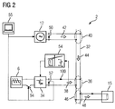
- FIG. 1 shows a schematic diagram of an electrical energy supply network.
- the electrical power supply network 2 is formed in the present embodiment as a stand-alone network 2, which is indeed connected to a centralized network 4, in normal operation However, it can be operated completely independently of this.
- the island grid 2 can be supplied with electrical energy from various electrical power sources.
- the electrical power sources include a solar cell 6, a wind turbine 8, a water wheel 10 and a diesel generator 12.
- the electrical energy from the electrical power sources may be in the direction 14 of one or more in FIG. 2 15 consumers are shown. If the electric power supply through the electrical power sources is greater than the consumers 15 can record, so an excess of electrical energy can be cached in energy storage.
- the energy stores comprise a rechargeable battery 16, a flywheel 18 and a double-layer capacitor 20.
- a fuel cell 22 is arranged as the electric power source. If the electrical power demand of the consumers 15 temporarily exceeds the electrical energy output by the electrical power sources, the electrical energy surplus stored in the energy stores can be retrieved again.
- the network formers 6, 8, 10, 12 regulate the grid voltage of the island grid 2 based on in 3 and 4 shown statics. These contrast the shape of the mains voltage of the retrieved from the island grid 2 electrical power. While the static characteristics are intrinsically predetermined in the diesel generator 12, to the solar cell 6, the wind turbine 8 and the water wheel 10 depending on the mains condition dependent regulated power converters 24 are imposed, which force these electrical power sources corresponding static characteristics, what in the context of FIG. 2 discussed in more detail becomes. If a flow of water can be regulated by the water wheel 10, for example with throttle valves and by-passes, as in FIG. 1 indicated by dashed lines, optionally be dispensed with an extra self-commutated converter 24.
- the network supports 16, 18, 20, 22 feed in a first approximation regardless of the state of the island grid 2 their currently available power in the island grid 2 a.
- the network supports 16, 18, 20, 22 in the present embodiment, depending on the available feed power dependent regulated converter 26 downstream.
- the accumulator 16 and the double-layer capacitor 20 may each be followed by a DC-DC converter 28 to compensate for voltage fluctuations of these two energy storage depending on their state of charge.
- the island grid 2 can be connected via a transformer 30 with other isolated networks 2, not shown.
- the island grid 2 is simplified below and explained with reference to a two-phase electrical power supply. All statements below can be extended to any number of phases in a manner known to those skilled in the art.
- the self-commutated power converter 24 of the solar cell 6 is an inverter 34. Since each self-commutated, an alternating voltage output power converter 24 usually includes an inverter, the following statements about the inverter 34 can be applied to all in the island network 2 of FIG. 1 shown self-guided Power converter 24 are transmitted. While the inverter 34 and the diesel generator 12 each feed an electrical inverter power 38 at an inverter connection point 36 and an electrical generator power 42 at a generator connection point 40 and thus maintain an electrical grid power 44, the consumer 15 takes the line network 32 at a consumer connection point 46 an electrical consumer power 48.
- the inverter power 38 and the generator power 42 must be synchronized with each other to avoid that the inverter 34 and the generator 12 with each other to exchange electrical power and how electrical consumers to each other.
- the dependence of the generator voltage 50 can be used by the generator power 42.
- the frequency of the generator voltage 50 decreases with increasing active component in the generator power 42, or the effective value of the generator voltage 50 decreases with increasing reactive component in the generator power 42.
- This dependence is modeled in the already mentioned static characteristics. If a plurality of electrical energy generators are interconnected with one or more consumers depending on the output power output, then a stable operating point with a stable output voltage arises, in which each individual electrical energy generator delivers electrical power and only the one or more electrical consumers deliver electrical power take up.
- the inverter voltage 52 is basically not dependent on the inverter power 38, it must be made artificially dependent on the inverter power 14 as already indicated. This is done by defining inverter static characteristics for the inverter and the inverter voltage 52, as in FIG. 2 indicated, is made dependent on correspondingly inverted inverter static characteristics 54 of the inverter power 38. In this way, the inverter 34 behaves like the generator 12 and can be synchronized with this via the static characteristics in the electrical power grid. As the actual network generator, this does not affect the solar cell 6 but the inverter 34 connected to it, which is why essentially only the inverter 34 is to be considered.
- the diesel generator 12 and / or the inverter 34 with its inverted static characteristics 54 can be controlled by a master computer 55, which will be discussed in more detail later.
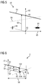
- FIG. 3 11 shows an active power diagram 56 with an inverter active power statistical characteristic 58 and a line network active power static characteristic curve 60 as seen by the inverter 34.
- FIG. 4 a reactive power diagram 62 with an inverter reactive power statistic 64 and a line network reactive power static characteristic 66 seen from the inverter 34 from.
- An active power diagram compares the active power 68 delivered or picked up by the two-pole to the frequency 70 of its delivered or received voltage. If the active power 68 is positive, the two-pole acts like a generator 72. If the active power 68 is negative, the two-pole acts like a consumer 74.
- the inverter active power statics characteristic 58 is predetermined as already mentioned.
- the line network active power statics curve 60 represents the behavior of the line network 4 from the perspective of the inverter 34 and is not one of them shown Dieselgenerator Wirk orientalsstatikkennline, the impedance of the load 15 and the impedance of the power system 32 dependent.
- the inverter 34 and the line network 32 seen from the inverter 34 are connected between the inverter power 38 and the power absorbed by the power network 32 electrical power at the inverter connection point 36 of the inverter operating point 76, in which the inverter Wirkschaftsstatikkennline 58 and the line network active power statics curve 60 intersect.
- the inverter operating point 76 the grid frequency 78 of the common mains voltage is given.
- the reactive power diagram 62 for any two-pole compares the reactive power 80 delivered or received by the two-pole with the rms value 82 of its delivered or received voltage. If the reactive power 80 is positive, the two-pole acts like an inductance 84. If the reactive power 80 is negative, the two-pole acts like a capacitance 86.
- the inverter reactive power statistic 64 is also given.
- the line system reactive power statistical curve 66 again represents the behavior of the line network 32 from the perspective of the inverter 34 and is dependent on a diesel generator reactive power static curve, not shown, the impedance of the load 15 and the impedance of the line network 32.
- the network effective value 88 of the common grid voltage can be read from the intersection between the inverter reactive-power statistical characteristic 64 and the line-system reactive-power statistical characteristic 66.
- the diesel generator 12 is supplied with chemical energy in the form of diesel and the inverter 34 with electrical energy from the solar cell 6.
- This external power supply 92 raises the open circuit voltage 90 and thus the static characteristic (in FIG. 5 the reactive power static characteristic 64) of the inverter 34 and the diesel generator 12 and thus enables the delivery of electrical power 38, 42 to the consumer 15. If the electrical load 15 is connected to the electrical energy supply network 2, so arises between the diesel generator 12, the inverter 34th and the electrical load 15, the above-mentioned operating point 76 a.
- the master computer 55 can start the combustion process in the diesel generator 12 and turn it on.
- the start of the diesel generator 12 causes a voltage ramp in the electrical power grid 2, which can be used to start the electrical power output of the inverter 34.
- the inverter 34 with the solar cell 6 is connected via a switch 94, which is controllable via the inverter voltage 52 at the inverter connection point 36. As soon as the inverter voltage 52 exceeds a specific threshold value, the switch is closed and the electrical energy supply of the inverter 34 is started from the solar cell 6.
- diesel generator 12 and the switch 94 may both be controlled by the master computer, as in FIG FIG. 2 indicated by a dashed line.
- the communication between the master computer 55 and the diesel generator 12 and / or the switch 94 may be via separate lines, as in FIG FIG. 2 shown.
- the master computer 55 can also transmit its signals via the electrical energy supply network 2 and superimpose the electrical line network power 44.
- the inverter 34 is at the point of open circuit voltage 90th
- the inverter 34 After triggering the start of the electrical power supply by the master computer 55, when the inverter 34 and diesel generator 12 both feed electrical power 38, 42 into the electrical power grid 2, the line grid Wirkschaftsstatikkennline 60 from the perspective of the inverter 34 depends on the generator 8, and both curves intersect at the inverter operating point 76. In order to move to the inverter operating point 76, the inverter 34 must provide additional active power 98. However, since the mains voltage at the inverter 34 is very small at the beginning of the electrical power supply, the additional active power 98 can essentially only exceed that in FIG FIG. 2 shown inverter current 100, which is also limited by the current limit of the inverter 34. As a result, the inverter 34 remains on its inverter active power characteristic 58 before the inverter operating point 76 at a limit operating point 102 stand.
- the diesel generator 12 may move freely to the inverter operating point 76 on its generator active power statistical characteristic curve, if appropriate, until it is switched off. Since the inverter 34 can not follow the generator 8, the generator moves back on its generator Wirkstatstatikkennline seen from the inverter operating point 76 back to provide a missing from the inverter 34 active power difference 103. From the point of view of the inverter 34, the line network 4 assumes a compensation operating point 104 on the line network active power statistical characteristic line 60. As a result, the inverter 34 outputs an inverter voltage 52, the one having a frequency difference 105 different frequency 70 to the mains voltage.
- the invention proposes to change the inverter voltage 52 in the case of the synchronization problem so that the inverter 34 can move freely again on its static characteristics 58, 64.
- the electrical power supply to the inverter 34 could be reduced from the solar cell 6. This has the effect that the static characteristics 58, 64 of the inverter 34 are shifted negatively by a defined amount 106. If the static characteristics 58, 64 of the inverter 34 are displaced, for example, so long that they run through the current compensation operating point 104 of the pipeline network, the inverter 34 can again move freely on its static characteristics 58, 64.
- the static characteristics 58, 64 of the inverter 34, and thus the power supply from the solar cell 6 could be slowly raised again to set the actually set by the master 55 mains voltage.
- the change in the static characteristic 58, 64 can be achieved in the simplest case, that the inverter 34 for the time of lowering the static characteristic 58, 64 of the mains voltage and thus the current compensation working point 104 of the power network 32 follows.
- the slope of the static characteristics 58, 64 of the inverter 34 could be changed briefly.
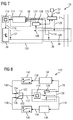
- FIG. 7 shows a section 108 from the electrical power grid 2 of FIG. 2 with a device 110 for controlling the inverter 34.
- the inverter 34 is hereinafter a self-commutated inverter.
- the device 110 may output a control signal 112 to a drive processor 114 of the inverter 34 based on the inverter power 38 fed into the line network 2, which in turn may output clock signals 116 based on the control signal 112 to switches (not shown) of the inverter 34 with which the inverter 34 the inverter voltage 52 is generated.
- the device 110 switches the operation of the inverter 34 between a control mode of operation and an error mode of operation. As long as there are no synchronization problems, the inverter 34 can contribute in regular operation mode to keep the mains voltage 118 in the line network 2 constant. In case of synchronization problems, the inverter 34 should follow the mains voltage 118.
- an error detection device 120 of the device 110 may monitor the inverter connection point 36 for synchronization problems and output a corresponding state signal 122 to the device.
- the fault detection device 120 can check whether an inverter current 100 has reached its maximum current I tot .
- the error detection device 120 can check whether there is currently a short circuit in the line network 4. This can be done, for example, by monitoring the level of the mains voltage 118 and comparing it with a threshold value. In the event of a short circuit, the mains voltage 118 falls below the threshold value.
- the error detection device 120 can check whether the inverter 34 is currently connected to the line network 2 as the only electrical power generation unit.
- the fault detection device 120 can receive, for example from the master 55, a parameterization signal 124 which indicates how many electrical power generation units are connected to the line network 2.
- the fault detection device 120 can feed a fault 126 in the control network 4 in the control mode, and thus direct the inverter 34 specifically from the inverter operating point 76. If the network power 20 changes significantly according to the introduced disturbance 126, it can be assumed that this response is caused by another generating unit with a static characteristic behavior.
- the time response must be adapted to the dominant time constant of the generator 12 in order to cause a frequency-voltage response in this case.
- the inverter power 38 is sensed via a power meter 128 based on the grid voltage 118 and the inverter current 100.
- the device 124 will be described in more detail below with reference to four exemplary embodiments.
- the drive processor 114, the inverter 34 and the power meter 128 are combined to form a controlled system 130, which is controlled by the device 110 via the actuating signal 112.
- FIG. 8 the first embodiment of the device 110 is shown.
- a switch 132 which can be controlled by the status signal 122 specifies in which of the two operating modes the inverter 34 of the controlled system 130 is to be controlled. For this purpose, the switch 132 is in a position for the control mode 134 and a position for the error operating mode 136 can be transferred.
- control mode 134 the inverter 34 will operate as in FIG FIG. 2 is controlled via the inverted inverter static characteristic curve 54 with a drive signal in such a way that the inverter 34 adapts to a predetermined static behavior and thus actively contributes to the maintenance of a constant mains voltage 118. Since the inverter 34 in this case has to deliver a specific inverter power 38 into the line network 2, the drive signal in the control mode 134 is to be referred to as a power control signal 138. Via a low-pass filter 140 with PT1 behavior, it is possible to attenuate fluctuations, which originate for example from noise, from the power control signal 138. The low-pass filtered power control signal 142 is finally output as the control signal 112 to the drive processor 114 in the regular operation mode 134 to set the inverter voltage 52.
- the controlled system 130 is controlled with a drive signal in such a way that the inverter voltage 52 follows the grid voltage 118.
- the drive signal should therefore in the error operating mode as a follow-up control signal 144th be designated.
- the sequencing control signal 144 may be derived from the grid voltage 118 via a phase locked loop 146, called PLL 146, in a manner known to those skilled in the art to stabilize the sequencing control signal 144. Variations in the sequence control signal 144 can be damped again via another low-pass filter 140, wherein the low-pass filtered sequence control signal 148 is output as the control signal 126 to the control processor 128.
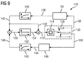
- FIG. 9 the second embodiment of the device 110 is shown.
- the low pass filtered power control signal 142 may be subtracted from the low pass filtered sequencer signal 148.
- the resulting control difference 150 may be supplied to a controller 152.
- a resulting control signal 154 may be obtained using the in FIG. 8 shown switch 132 in error mode 136 in a manner not shown directly as a control signal 112 to the drive processor 114 output.
- the low-pass filtered follow-up control signal 148 and thus the line voltage 118 represents a command variable for the inverter voltage 52.
- the low-pass filtered power control signal 142 is output as a control signal 112.
- the low-pass filtered power control signal 142 may also be switched to the control signal 154.
- the inverter voltage 52 to be set is directly apparent.
- a weighting factor for the control difference 150 can be preset via the controller 152, which specifies the speed of the adaptation of the inverter voltage 52 to the mains voltage 118.
- the control difference 150 is completely suppressed, so that only the low-pass filtered power control signal 142 is output as a control signal 112.
- the gain factor of exactly 0 therefore replaces the switch 132 in the position for the control mode 134.
- the low-pass filtered sequencing control signal 148 is output because the low-pass filtered power control signal 142 cancels by the negative lock in front of the regulator 152 and the positive lock after the regulator 152 at that gain.
- the gain factor of exactly 1 therefore replaces the switch 132 in the fault mode 136 position.
- the controller 152 can be used to switch continuously and without jumps from the normal operating mode 134 into the error operating mode 136 and vice versa.
- the use of the switch 132 can optionally be completely dispensed with in the third exemplary embodiment. If the switch is nevertheless used after the controller 152, the controller 152 can also be parameterized invariably and the speed of the adaptation of the inverter voltage 52 to the mains voltage 118 can be permanently preset.
- the third exemplary embodiment for calculating the actuating signal 126 which is used to set the frequency of the inverter voltage based on the inverted inverter active power static characteristic curve 38, is shown.
- the power meter 144 detects the active power 68 of the inverter power 38 based on the grid voltage 118, the inverter current 100, and the phase shift between both quantities. Via the inverted inverter active power statics curve 54 the drive frequency is determined, which must set the inverter 34 to fulfill its predetermined active power statics to actively contribute to the frequency maintenance in the grid voltage 118.
- This drive frequency is analogous to below FIG. 8 Power frequency 156 denotes.
- the analog to FIG. 8 low-pass filtered power frequency 158 over one to FIG. 8 analog switch 132 in the control mode 134 are output as the adjustment frequency 160 for the inverter voltage 52. From the PLL 146, the current network frequency 162 can be seen.
- the analog to FIG. 8 Low pass filtered network frequency 165 may be output in error mode 136 as the drive frequency 160 for the inverter voltage 52.
- the control frequency 160 can be converted into an inverter voltage phase 168 for the inverter voltage 52.
- a mains voltage phase 170 can be derived in the following and low-pass filtered.
- the low-pass filtered mains voltage phase 172 and the inverter voltage phase 168 may then be further processed into the control signal 112 as well as the low-pass filtered power voltage 142 and the low-pass filtered follower voltage 148 in FIG FIG. 9 ,
- the switch 132 is shown after the controller 152, which allows the controller 152 to be invariably preset.
- FIG. 11 4 the fourth exemplary embodiment for calculating the actuating signal 112, which is used to set the effective value of the inverter voltage 52 based on an inverted inverter reactive power statistical characteristic 174, is shown.
- the power meter 128 detects the reactive power 80 output by the inverter 34.
- the required inverter effective power value 176 for the inverter voltage 174 becomes the inverted inverter reactive power static characteristic 174 52 is output so that the inverter 34 follows its predetermined reactive power statics.
- Inverter RMS value 176 is finally low pass filtered.
- the mains voltage effective value 180 can be determined, which is also low-pass filtered.
- the low-pass filtered inverter rms value 182 and the low-pass filtered net voltage rms value 184 are then further processed into the control signal 112 as well as the low-pass filtered power voltage 142 and the low-pass filtered follower voltage 148 in FIG FIG. 9 ,
- the switch 132 is shown after the controller 152, which allows the controller 152 to be invariably preset.
- FIG. 12 By way of example, a method 186 for switching between the normal operation mode 134 and the error operation mode 136 is illustrated.
- the method begins in step 188 with determining the RMS value 176, the frequency 156 and the phase 168 for the inverter voltage 52 from the inverted static characteristics 52, 174.
- steps 190, 192 and 194 the above-mentioned conditions for generating the state signal 122 are successively checked.
- step 190 While it is checked in step 190 whether there is a short circuit, it is checked in step 192 whether the inverter 34 is not yet working on its inverter current limit I ges and in step 194, if no other power generator connected to the line network 2.
- the inverter voltage 52 is in step 198 in the control mode 134 based on the RMS value 176, the frequency 156 and the Phase 158 generated from step 188. Otherwise, the method 186 enters the error mode 136 at step 196 and generates the inverter voltage 54 based on the rms value 176, frequency 156, and phase 158 of the line voltage 118.
- step 196 it may be checked when one of the conditions from steps 190-194 is again met to move the method 186 to step 198. In this way, the inverter voltage 52 is corrected in the error operating mode 136, so that the inverter 34 can actively contribute to the maintenance of the grid voltage 118 in a timely manner.
- the method 186 may be automatically transferred to step 198 after a certain time.
Landscapes
- Engineering & Computer Science (AREA)
- Power Engineering (AREA)
- Supply And Distribution Of Alternating Current (AREA)
Description
Die Erfindung betrifft ein Verfahren zum Erhalten einer Netzspannung in einem elektrischen Energieversorgungsnetz, eine Steuervorrichtung zur Durchführung des Verfahrens, einen Netzbildner zum Erhalten einer Netzspannung in einem elektrischen Energieversorgungsnetz und ein elektrisches Energieversorgungsnetz mit dem Netzbildner.The invention relates to a method for obtaining a mains voltage in an electrical energy supply network, to a control device for carrying out the method, to a network generator for obtaining a mains voltage in an electrical energy supply network and to an electrical energy supply network with the network former.
Elektrische Energieversorgungsnetze mit Netzbildern zum Erhalten einer Netzspannung in dem elektrischen Energieversorgungsnetz sind beispielsweise aus der
Es ist Aufgabe der Erfindung, die Erhaltung einer Netzspannung in einem elektrischen Energieversorgungsnetz zu verbessern.It is an object of the invention to improve the maintenance of a mains voltage in an electrical energy supply network.
Die Aufgabe wird durch die Merkmale der unabhängigen Ansprüche gelöst. Die abhängigen Ansprüche enthalten bevorzugte Weiterbildungen der Erfindung.The object is solved by the features of the independent claims. The dependent claims contain preferred developments of the invention.
Der Erfindung liegt die Überlegung zugrunde, dass Blackstarts oder Schwarzstarts genannte Wiederanläufe in elektrischen Energieversorgungsnetzen in dezentralen elektrischen Energieversorgungsnetzen, Inselnetze genannt, eine besondere Herausforderung darstellen. Unter einem Schwarzstart wird nachstehend die Fähigkeit des Inselnetzes verstanden, von einem abgeschalteten Zustand aus eine gemeinsame Netzspannung aufzubauen und zu erhalten. Dazu müssen während des Schwarzstarts alle an das Inselnetz angeschlossenen Netzbildner einen gemeinsamen Arbeitspunkt zum Aufbau einer stabilen Netzspannung finden.The invention is based on the consideration that blackstarts or blackstarts called restarting in electrical energy supply networks in decentralized electrical energy supply networks, called island networks, present a special challenge. A black start is understood below to mean the ability of the stand-alone network to build up and maintain a common mains voltage from a disconnected state. For this purpose, during the black start, all network creators connected to the stand-alone grid must find a common operating point for establishing a stable grid voltage.
Ferner liegt der Erfindung die Überlegung zugrunde, dass in einem elektrischen Energieversorgungsnetz zwischen Netzbildnern und Netzstützern unterschieden wird. Netzstützer speisen dabei in erster Näherung unabhängig vom Zustand des Netzes eine verfügbare Leistung in das elektrische Energieversorgungsnetz ein und wirken damit als Stromquelle. Demgegenüber beteiligen sich Netzbildner an der Regelung der Netzspannung und wirken so als Spannungsquelle. Dabei ist die aktuell abgegebene Leistung abhängig von der zu diesem Zeitpunkt vom elektrischen Energieversorgungsnetz abgerufenen elektrischen Leistung. In einem elektrischen Energieversorgungsnetz muss mindestens ein Netzbildner vorhanden sein. Ein stabiler Betrieb mehrerer Netzbildner in einem elektrischen Energieversorgungsnetz erfolgt bevorzugt mit Hilfe einer sogenannten Statikkennlinie, die eine vom elektrischen Energieversorgungsnetz abgerufene elektrische Leistung der Netzspannung gegenüberstellt. Jeder Netzbildner im Inselnetz ermittelt mit Hilfe dieser Statikkennlinien seine aktuelle einzuspeisende Spannung. Ein im elektrischen Energieversorgungsnetz aufeinander abgestimmter Arbeitspunkt zwischen mehreren Netzbildnern ist erreicht, wenn alle Netzbildner eine gleiche einzuspeisende Spannung abgeben.Furthermore, the invention is based on the consideration that a distinction is made between network creators and network supporters in an electrical energy supply network. Mains sup- plies supply, as a first approximation, an available power to the electrical power supply network regardless of the state of the network and thus act as a power source. In contrast, network designers participate in the regulation of the mains voltage and thus act as a voltage source. In this case, the currently delivered power is dependent on the electrical power retrieved from the electrical power supply network at this time. In an electrical energy supply network, at least one network former must be present. A stable operation of several network formers in an electrical energy supply network is preferably carried out with the aid of a so-called static characteristic which compares an electrical power called up by the electrical energy supply network with the mains voltage. Each network generator in the stand-alone grid determines its current voltage to be fed using these static characteristics. A working point between several network formers which is coordinated in the electrical energy supply network is achieved when all network formers deliver an identical voltage to be fed in.
Darüber hinaus liegt der Erfindung die Überlegung zugrunde, dass es am günstigsten wäre, zunächst einen einzigen Netzbildner die Netzspannung vorgeben zu lassen, und die restlichen Netzbildner dann zum elektrischen Energieversorgungsnetz dazu zu schalten. Inselnetze zeichnen sich jedoch durch eine geringe Hierarchie aus. Die Netzbildner können hier nur gemeinsam mit den Verbraucherlasten verschaltet werden. Zwar könnte hier dennoch ein einzelner Netzbildner zunächst die Netzspannung vorgeben, durch die angeschlossenen Verbraucher kann die während des Schwarzstarts vorhandene Verbraucherlast für diesen einzelnen Netzbildner zu groß sein, um die Netzspannung zu erzeugen. Dies kann nur dadurch gelöst werden, dass der Schwarzstart gemeinsam mit mindestens zwei koordinierten Netzbildnern erfolgt. Diese Koordination könnte asynchron erfolgen, wobei sich jeder der zu koordinierenden Netzbildner anhand ihrer eigenen aktuell in das elektrische Energieversorgungsnetz eingespeisten Leistung über die Statikkennlinie die in das Netz einzuspeisende Spannung berechnen.In addition, the invention is based on the consideration that it would be best to first let a single network generator specify the mains voltage, and then switch the remaining network formers to the electrical energy supply network. However, island grids are characterized by a low hierarchy. The network formers can only be interconnected with the consumer loads here. Although here could still specify a single Netzbildner first, the mains voltage, by the connected consumers, the existing during the black start load load for this individual Netzbildner be too large to generate the mains voltage. This can only be solved by doing the black start together with at least two coordinated network builders. This coordination could be asynchronous, with each of the network builders to be coordinated calculate the voltage to be fed into the grid by means of its own power currently fed into the electrical energy supply network via the static characteristic curve.
Der Erfindung liegt jedoch die Erkenntnis zugrunde, dass sich auf dem asynchronen Weg eine gemeinsame Netzspannung nicht einstellen lässt, wenn einer der koordinierten Netzbildner auf seiner Statikkennlinie den anderen Netzbildnern nicht schnell genug folgen kann. Dies soll beispielhaft an Netzbildnern erklärt werden, die eine Stromgrenze besitzen, die sie nicht überschreiten können. Da Netzbildner wie bereits erwähnt als Spannungsquellen arbeiten müssten sie fähig sein unendlich hohe Ströme abzugeben, was in der Praxis jedoch nicht der Fall ist. An Punkten auf der Statikkennlinie mit sehr niedrigen Spannungen müssen die Netzbildner hohe Leistungsflüsse in das elektrische Energieversorgungsnetz durch entsprechend hohe Ströme ausgleichen. Kann er den entsprechend hohen Strom nicht aufbringen, bleibt seine eigene aktuell in das elektrische Energieversorgungsnetz eingespeiste Leistung und damit seine in das elektrische Energieversorgungsnetz einzuspeisende Spannung konstant, so dass er auf einem Punkt der Statikkennlinie stehen bleibt und sich nicht mehr weiter bewegt. In der Folge können die zu koordinierenden Netzbildner keine gemeinsame Netzspannung aufbauen.However, the invention is based on the finding that a common line voltage can not be set on the asynchronous path if one of the coordinated network elements can not follow the other network elements quickly enough on its static characteristic curve. This should be explained by way of example to network builders who have a current limit that they can not exceed. Since Netzbildner work as already mentioned as power sources, they would be able to deliver infinitely high currents, which is not the case in practice. At points on the static characteristic curve with very low voltages, the network formers have to compensate for high power flows into the electrical energy supply network by means of correspondingly high currents. If he can not afford the correspondingly high current, his own currently fed into the electrical power grid power and thus its fed into the electrical power grid voltage remains constant, so that it stops at one point of the static characteristic and stops moving. As a result, the network creators to be coordinated can not establish a common network voltage.
Das Problem könnte zwar auf synchronem Weg gelöst werden, indem ein gemeinsamer Master die Sollwerte für die Netzspannung hart vorgibt. Auf diese Weise könnte vermieden werden, dass den Netzbildnern aufgrund zu kleiner temporärer Netzspannungen zu große Ströme abverlangt werden. Jedoch müsste jeder einzelne Netzbildner mit dem Master verbunden sein, die gerade bei räumlich über mehrere Kilometer verteilten Netzbildnern zu erheblichen Kosten, einer hohen Störanfälligkeit und damit zu einer unzureichenden Verfügbarkeit führen kann.Although the problem could be solved in a synchronous way by a common master sets the setpoints for the mains voltage hard. In this way, it could be avoided that the network formers are required to carry too large currents because of too small temporary mains voltages. However, each individual network generator would have to be connected to the master, which can lead to considerable costs, a high susceptibility to interference and thus to insufficient availability, especially in the case of network creators distributed over several kilometers.
Demgegenüber ist es Idee der Erfindung, den auf seiner Statikkennlinie stehengebliebenen Netzbildner zu bewegen, und quasi einen Schubs zu geben, so dass er sich wieder auf seiner Statikkennlinie bewegen kann. Dies wird dadurch erreicht, dass wenn der Netzbildner auf seiner Statikkennlinie stehen geblieben ist, er auf einen neuen Punkt auf der Statikkennlinie verschoben wird, aus dem er für die abzugebende Leistung einen Strom unterhalb seiner Stromgrenze abgeben muss. Somit kann er durch den nun wieder variablen Ausgangsstrom seine an das elektrische Energieversorgungsnetz abzugebende Leistung erhöhen und sich frei auf der Statikkennlinie bewegen.In contrast, it is an idea of the invention to move the network structure left standing on its static characteristic, and to give a kind of a push, so that he is back on his Can move statics characteristic. This is achieved by the fact that, if the network generator has stopped on its static characteristic, it is moved to a new point on the static characteristic curve from which it must deliver a current below its current limit for the power to be output. Thus, it can increase its output to the electrical power grid power through the now variable output current and move freely on the static characteristic.
Die Erfindung gibt daher ein Verfahren zum Synchronisieren einer Einspeisespannung mit einer Netzspannung eines elektrischen Energieversorgungsnetzes an wobei eine Eigenschaft der Einspeisespannung basierend auf einer Statikkennlinie bestimmbar ist, wobei die Statikkennlinie die Eigenschaft der Einspeisespannung einer Einspeiseleistung gegenüberstellt, wobei die Einspeiseleistung durch das elektrische Energieversorgungsnetz bei der angelegten Einspeisespannung aufgenommen wird, und wobei die Eigenschaft der Einspeisespannung an einen bestimmten Wert angepasst wird, wenn eine Grenze für die Einspeiseleistung erreicht ist. Die Eigenschaften der Einspeisespannung beziehungsweise der Netzspannung sind beispielsweise die eingangs genannte Frequenz, Phasenlage und/oder der Effektivwert der entsprechenden Spannung.The invention therefore provides a method for synchronizing a supply voltage with a mains voltage of an electrical power supply network wherein a property of the supply voltage can be determined based on a static characteristic, the static characteristic is the feed voltage characteristic of a feed-in, wherein the feed-in by the electric power grid in the applied Supply voltage is added, and wherein the property of the supply voltage to a certain value is adjusted when a limit for the feed-in power is reached. The properties of the supply voltage or the mains voltage are, for example, the frequency mentioned at the outset, the phase position and / or the effective value of the corresponding voltage.
Durch die Erfindung lässt sich in einem elektrischen Energieversorgungsnetz eine gemeinsame Netzspannung asynchron aufbauen, ohne dass einzelne Netzbildner auf ihren Statikkennlinien stehen bleiben. So können beim Aufbau und Betrieb des elektrischen Energieversorgungsnetzes Kosten durch weniger Material und eine erhöhte Zuverlässigkeit gespart werden. In einer Weiterbildung der Erfindung ist die Grenze für die Einspeiseleistung erreicht, wenn eine maximal an das Energieversorgungsnetz abgebbarer Strom erreicht und/oder die Einspeiseleistung negativ ist. Dieser Weiterbildung liegt die Überlegung zugrunde, dass bei leistungselektronischen Komponenten wie Wechselrichtern und Frequenzumrichtern aufgrund ihrer Halbleiterbauelemente feste Stromgrenzen besitzen, die nicht überschritten werden können.As a result of the invention, a common mains voltage can be established asynchronously in an electrical power supply network without individual network formers remaining on their static characteristic curves. Thus, the construction and operation of the electrical energy supply network costs can be saved by less material and increased reliability. In a development of the invention, the limit for the feed-in power is reached when a maximum power that can be delivered to the power grid is reached and / or the feed-in power is negative. This development is based on the consideration that in power electronic components such as inverters and frequency converters due their semiconductor devices have fixed current limits that can not be exceeded.
In einer anderen Weiterbildung der Erfindung ist der bestimmte Wert kleiner oder gleich der entsprechenden Eigenschaft der Netzspannung. Das heißt, dass als Grundlage für den bestimmten Wert der Istwert der entsprechenden Eigenschaft der Netzspannung herangezogen werden kann. Zwar könnte die bestimmte Spannung in jeder beliebigen Weise neu gewählt werden, dass sich der Netzbildner wieder frei auf der Statikkennlinie bewegen kann. So wäre es denkbar durch eine Interpolation des letzten Verlaufs die bestimmte Spannung rechnerisch zu bestimmen, oder intern im Netzbildner einen Hilfswert zu hinterlegen, zu dem sich der Netzbildner auf der Statikkennlinie bewegt. Durch die vorgeschlagene Weiterbildung steht jedoch ohne weitere Rechnerarchitektur, Kommunikationsmittel oder andere interne Speichererfordernisse am Netzbildner ein Richtwert zur Verfügung, mittels dem der Netzbildner seinen Punkt auf der Statikkennlinie neu ausrichten kann, um sich wieder frei bewegen zu können.In another embodiment of the invention, the specific value is less than or equal to the corresponding property of the mains voltage. This means that the actual value of the corresponding characteristic of the mains voltage can be used as the basis for the specific value. Although the particular voltage could be re-selected in any way that the network generator can move freely on the static characteristic again. For example, it would be conceivable to computationally determine the specific voltage by interpolation of the last curve, or to store an auxiliary value internally in the network former to which the network generator moves on the static characteristic curve. The proposed development, however, without a further computer architecture, communication means or other internal storage requirements on Netzbildner a guideline available by means of which the network builder can reorient his point on the static characteristic in order to move freely again.
In einer bevorzugten Weiterbildung der Erfindung weist die Statikkennlinie einen Fußpunkt auf, der zum Anpassen der Eigenschaft der Einspeisespannung an den bestimmten Wert verschoben wird. Durch die Verschiebung des Fußpunktes wird die abzugebende Einspeiseleistung des das angegebene Verfahren ausführenden Netzbildners bei den aktuellen Eigenschaften der Einspeiseleistung reduziert. Durch diese Reduktion wird der Netzbildner aus seiner Leistungsgrenze gezogen und kann sich so wieder frei auf seiner Statikkennlinie bewegen.In a preferred embodiment of the invention, the static characteristic on a base point, which is moved to adjust the property of the supply voltage to the specific value. Due to the displacement of the base point, the feed-in power to be delivered by the network generator carrying out the specified method is reduced in the case of the current characteristics of the feed-in power. As a result of this reduction, the mesh former is pulled out of its performance limit and can thus move freely on its static characteristic curve again.
In einer anderen Weiterbildung der Erfindung wird zum Verschieben des Fußpunktes eine zugeführte Primärenergie reduziert, aus der die Einspeiseleistung umgewandelt wird. Durch die reduzierte Primärenergiezufuhr wird automatisch auch die Einspeiseleistung reduziert, so dass kein weiterer Umprogrammieraufwand an der Statikkennlinie selbst notwendig ist.In another embodiment of the invention, an applied primary energy is reduced to move the base point, from which the feed-in power is converted. Due to the reduced primary energy supply, the feed-in power is also automatically reduced, so that no further reprogramming effort is necessary on the static characteristic curve itself.
In besonders bevorzugter Weise kann der Fußpunkt der Statikkennlinie auf seinen ursprünglichen Wert zurückgeschoben werden, wenn die Einspeisespannung kleiner als die Grenze für die Einspeiseleistung ist. Auf diese Weise kann der Netzbildner nach seiner Befreiung aus der Leistungsgrenze wieder an der Spannungserhaltung der von einer übergeordneten Einheit vorgegebenen Netzspannung in ihrer Frequenz und in ihrem Effektivwert beitragen.In a particularly preferred manner, the base point of the static characteristic curve can be returned to its original value if the supply voltage is less than the limit for the feed-in power. In this way, the network former after its liberation from the power limit again contribute to the voltage maintenance of the predetermined by a parent unit mains voltage in their frequency and in their rms value.
In einer alternativen oder zusätzlichen Weiterbildung der Erfindung ist die Statikkennlinie linear und weist eine Steigung auf, die zum Anpassen der Eigenschaft der Einspeisespannung an den bestimmten Wert verändert wird. Auf diese Weise kann die Einspeiseleistung des Netzbildners bei den aktuellen Eigenschaften seiner Einspeisespannung ebenfalls reduziert werden, so dass der Netzbilder aus seiner Leistungsgrenze herausgezogen wird.In an alternative or additional development of the invention, the static characteristic is linear and has a slope which is changed to adapt the property of the supply voltage to the determined value. In this way, the feed power of the network generator can also be reduced in the current characteristics of its supply voltage, so that the network images is pulled out of its power limit.
In einer besonderen Weiterbildung wird die Steigung der Statikkennlinie auf ihren ursprünglichen Wert zurückgesetzt, wenn die Einspeisespannung kleiner als die Grenze für die Einspeiseleistung ist.In a particular development, the slope of the static characteristic curve is reset to its original value if the supply voltage is less than the limit for the feed-in power.
In einer anderen Weiterbildung der Erfindung wird die Einspeisespannung an das elektrische Energieversorgungsnetz nach dem Empfang eines vorbestimmten Einschaltsignals angelegt. Das heißt, dass das Einschaltsignal den Schwarzstart auslöst, ab dem der entsprechende Netzbildner sich auf einen Punkt auf seinen Statikkennlinien mit den Solleigenschaften für die Netzspannung bewegen muss. Diese Solleigenschaften brauchen dem Netzbildner jedoch nicht explizit mitgeteilt zu werden, sondern er bewegt sich aufgrund dem Statikkennlinienverlauf des elektrischen Energieversorgungsnetzes aus Sicht seines Einspeisepunktes automatisch in einen Gleichgewichtspunkt, in dem die Solleigenschaften für die Netzspannung gegeben sind. Bleibt der Netzbildner aufgrund einer bestimmten Leistungsgrenze auf seiner Statikkennlinie stehen, so kann er mit dem angegebenen Verfahren wieder bewegt werden, so dass er diesen Gleichgewichtszustand sicher erreichen kann. Durch das Einschaltsignal können alle an der Erhaltung der Netzspannung beteiligten Netzbildner synchron schwarz gestartet werden.In another embodiment of the invention, the feed voltage is applied to the electrical power grid after receiving a predetermined turn-on signal. This means that the switch-on signal triggers the black start, after which the corresponding network generator must move to a point on its static characteristics with the nominal properties for the mains voltage. However, these nominal properties do not need to be explicitly communicated to the network former, but, as a result of the static characteristic curve of the electrical energy supply network, it automatically moves from the point of view of its feed point into an equilibrium point in which the nominal properties for the network voltage are given. If the network former remains on its static characteristic due to a certain power limit, it can be moved again using the specified method so that it can be used Can reach equilibrium safely. Due to the switch-on signal, all network creators involved in the maintenance of the mains voltage can be started synchronously in black.
In einer besonderen Weiterbildung ist das Einschaltsignal ein Anstieg einer Eigenschaft der Netzspannung.In a particular embodiment, the switch-on signal is an increase in a property of the mains voltage.
In einer anderen Weiterbildung der Erfindung umfasst das angegebene Verfahren den Schritt Erfassen eines Einschaltsignals vor dem Anpassen der Einspeisespannung an die aktuell an das Energieversorgungsnetz abgegebene Einspeiseleistung. Durch das Einschaltsignal können alle am Schwarzstart beteiligten Netzbildner synchron gestartet und über das elektrische Energieversorgungsnetz untereinander synchronisiert werden, ohne dass eine extra Infrastruktur für ihre Kommunikation untereinander eingeführt werden müsste. Es reicht damit aus, wenn ein Master an einen der Netzbildner angeschlossen ist, der diesem Netzbildner das Startsignal gibt. Der vom Master gestartete Netzbildner kann einen anfänglichen Spannungsanstieg erzeugen, den alle anderen Netzbildner messen können, um in den Schwarzstart des elektrischen Energieversorgungsnetzes einzusteigen.In another development of the invention, the specified method comprises the step of detecting a switch-on signal before adapting the feed-in voltage to the feed-in power currently delivered to the energy supply network. The switch-on signal enables all network creators participating in the black start to be started synchronously and synchronized with one another via the electrical power supply network without having to introduce an extra infrastructure for their communication with one another. It is sufficient if a master is connected to one of the network creators, who gives the start signal to this network creator. The network originator started by the master can generate an initial voltage rise which all other network generators can measure in order to enter the black start of the electrical power supply network.
In einer bevorzugten Weiterbildung der Erfindung wird Eigenschaft der Einspeisespannung nach Empfang des vorbestimmten Signals basierend auf einem Sollverlauf folgegeregelt. Auf diese Weise können die an der Erhaltung der Netzspannung beteiligten Netzbildner mit einer vorbestimmbaren Geschwindigkeit an den zuvor genannten Gleichgewichtspunkt auf Ihrer Kennlinie herangeführt werden, was die Wahrscheinlichkeit, dass Netzbildner überhaupt auf Ihren Statikkennlinien stehen bleiben senkt.In a preferred development of the invention, the property of the supply voltage is subsequently regulated on receipt of the predetermined signal based on a desired course. In this way, the network builders involved in the maintenance of the mains voltage can be introduced at a predeterminable speed to the aforementioned equilibrium point on their characteristic curve, which reduces the likelihood that network formers will ever remain standing on their static characteristic curves.
In einer besonders bevorzugten Weiterbildung der Erfindung ist die folgegeregelte Eigenschaft der Einspeisespannung der Effektivwert der Einspeisespannung. Der entsprechend geregelte Spannungsanstieg ist dann die bereits genannte Spannungsrampe, die beispielsweise aufgrund einer langsamen Parallelverschiebung der Blindleistungskennlinie des entsprechenden Netzbildners beim Schwarzstart entsteht. Durch den geregelten Anstieg des Effektivwerts der Spannung können Änderungen der einzelnen Einspeisespannung im elektrischen Energieversorgungsnetz beeinflusst werden, die aufgrund von Induktionsströmen zu entsprechenden Störungen im elektrischen Energieversorgungsnetz führen könnten.In a particularly preferred development of the invention, the sequence-controlled property of the feed voltage is the effective value of the feed voltage. The correspondingly regulated voltage increase is then the already mentioned voltage ramp, which, for example, due to a slow parallel displacement the reactive power characteristic of the corresponding network generator at black start arises. The controlled increase in the effective value of the voltage can influence the changes in the individual supply voltage in the electrical energy supply network, which could lead to corresponding disturbances in the electrical energy supply network due to induction currents.
In einer alternativen Weiterbildung ist der Sollverlauf rampenförmig.In an alternative development, the desired course is ramp-shaped.
In einer zusätzlichen Weiterbildung ist eine zeitliche Länge der Rampenform kürzer, als eine Übertragungsdauer des Einschaltsignals. Das heißt, dass die einzelnen, nicht an den Master angeschlossenen Netzbildner den Spannungsanstieg detektieren sollten, bevor der an den Master angeschlossene Netzbildner in einen stationären Zustand übergeht.In an additional development, a time length of the ramp shape is shorter than a transmission duration of the switch-on signal. This means that the individual network devices not connected to the master should detect the voltage increase before the network device connected to the master changes to a stationary state.
In einer zusätzlichen Weiterbildung der Erfindung umfasst das angegebene Verfahren den Schritt Erhöhen der Einspeiseleistung an das elektrische Energieversorgungsnetz basierend auf einer Sollform für die Netzspannung. Die Sollform für die Netzspannung kann beispielsweise von einem Master vorgegeben werden, der mit ausschließlich einem einzigen Netzbildner im elektrischen Energieversorgungsnetz kommuniziert. Durch die angegebene Erfindung können dann alle anderen Netzbildner ihre Ausgabespannung an die Sollform der Netzspannung anpassen, ohne dass weitere Kommunikationsmittel als das eigentliche elektrische Energieübertragungsnetz zur Synchronisation der einzelnen Netzbildner untereinander notwendig sind.In an additional development of the invention, the specified method comprises the step of increasing the feed-in power to the electrical power grid based on a desired form for the grid voltage. The desired form for the mains voltage can for example be specified by a master who communicates with only a single network generator in the electrical energy supply network. By the specified invention, then all other network formers can adjust their output voltage to the desired shape of the mains voltage, without further communication means than the actual electrical power transmission network for synchronization of the individual network formers with each other are necessary.
In einer besonderen Weiterbildung der Erfindung umfasst die Statikkennlinie eine Blindleistungsstatikkennlinie, die die Blindleistung der Einspeiseleistung dem Effektivwert der Einspeisespannung gegenüberstellt. Da Blindleistung eine Leistungsform, die periodisch zwischen einem elektrischen Energieerzeuger und einem elektrischen Verbraucher hin- und herpulsiert, wird sie beispielsweise zum Betrieb von Asynchronmotoren benötigt. Über die Zufuhr von Blindleistung zum elektrischen Energieversorgungsnetz kann der Erhalt der Amplitude und damit der Effektivwert der Netzspannung beeinflusst werden, da die zugeführte Blindleistung Induktionsströme im Netz erzeugt, die die Netzspannung beeinflussen.In a particular embodiment of the invention, the static characteristic comprises a reactive power statics characteristic curve which compares the reactive power of the feed-in power to the effective value of the feed-in voltage. Because reactive power is a form of power that periodically paces back and forth between an electric power generator and an electrical consumer, For example, it is needed to operate asynchronous motors. The supply of reactive power to the electrical energy supply network, the receipt of the amplitude and thus the rms value of the mains voltage can be influenced, since the supplied reactive power generates induced currents in the network, which affect the mains voltage.
In einer bevorzugten Weiterbildung der Erfindung umfasst das angegebene Verfahren den Schritt Verschieben der Blindleistungsstatikkennlinie zum Erhöhen der Einspeiseleistung an das elektrische Energieversorgungsnetz. Durch die Verschiebung der Blindleistungsstatikkennlinie und der damit verbundenen Beeinflussung der Einspeisespannung kann eine Spannungsrampe erzeugt werden. Durch eine definierte Verschiebung der Blindleistungsstatikkennlinie über die Zeit kann die Form der Spannungsrampe über die Zeit einer vordefinierten Form angepasst werden.In a preferred development of the invention, the specified method comprises the step of shifting the reactive power statics curve to increase the feed-in power to the electrical energy supply network. By shifting the reactive power statics characteristic and the associated influence on the supply voltage, a voltage ramp can be generated. Through a defined shift of the reactive power statics characteristic curve over time, the shape of the voltage ramp can be adapted over time to a predefined form.
In einer anderen Weiterbildung der Erfindung umfasst die Statikkennlinie eine Wirkleistungsstatikkennlinie, die die Wirkleistung der Einspeiseleistung der Frequenz der Einspeisespannung gegenüberstellt, und die während der Erhöhung der Einspeiseleistung an das elektrische Energieversorgungsnetz konstant gehalten wird. Bei einem Generator ist die Wirkleistung abhängig vom Produkt aus Winkelgeschwindigkeit und Drehmoment. Dieses Generatorverhalten kann jedem Netzbildner, wie beispielsweise einem Wechselrichter mit angeschlossener Solarzelle durch geeignete Regelkreise aufgezwungen werden, so dass die Netzfrequenz des Energieversorgungsnetzes durch die Regelung über dem Energieversorgungsnetz zugeführte Wirkleistung konstant gehalten werden kann.In another refinement of the invention, the static characteristic curve comprises an active power static characteristic curve which compares the active power of the feed-in power with the frequency of the feed-in voltage and which is kept constant during the increase in the feed-in power to the electrical power supply system. For a generator, the active power depends on the product of angular velocity and torque. This generator behavior can be imposed on each network former, such as an inverter with a connected solar cell by suitable control circuits, so that the grid frequency of the power grid can be kept constant by the control of the power supply network supplied active power.
Die Erfindung gibt auch eine Steuervorrichtung zur Durchführung des angegebenen Verfahrens an.The invention also provides a control device for carrying out the specified method.
In einer Weiterbildung weist die angegebene Steuervorrichtung einen Speicher und einen Prozessor auf. Dabei ist das Verfahren in Form eines Computerprogramms in dem Speicher hinterlegt und der Prozessor zur Ausführung des Verfahrens vorgesehen, wenn das Computerprogramm aus dem Speicher in den Prozessor geladen ist.In a further development, the specified control device has a memory and a processor. In this case, the method is stored in the form of a computer program in the memory and the processor provides for executing the method when the computer program is loaded from memory into the processor.
Die Erfindung gibt auch einen Netzbildner für ein elektrisches Leistungsnetz an, der einen elektrischen Energieerzeuger zum Abgeben einer Einspeisespannung in ein elektrisches Energieversorgungsnetz mit einer Netzspannung und eine angegebene Steuervorrichtung umfasst.The invention also provides a network generator for a power electrical network, comprising an electric power generator for outputting a feed voltage into an electrical power grid having a grid voltage and a specified controller.
In einer Weiterbildung umfasst der angegebene Netzbildner einen Energiespeicher zum Aufnehmen einer elektrischen Energie aus dem Energieversorgungsnetz. Durch den Energiespeicher kann der Netzbildner im elektrischen Leistungsnetz oder elektrischen Energieversorgungsnetz auch als Verbraucher wirken und elektrische Energie aufnehmen, wenn dies erforderlich sein sollte.In a further development, the specified network generator comprises an energy store for receiving an electrical energy from the energy supply network. Through the energy storage of the network generator in the electrical power network or electrical power grid can also act as a consumer and absorb electrical energy, if necessary.
In einer besonderen Weiterbildung ist der Energieerzeuger ein Wechselrichter, der ausgebildet ist, elektrische Energie aus einer Gleichspannungsquelle in die Einspeisespannung umzuwandeln.In a particular embodiment, the energy generator is an inverter which is designed to convert electrical energy from a DC voltage source into the supply voltage.
Die Erfindung gibt auch ein elektrisches Energieversorgungsnetz an, das einen Netzbildner zum Abgeben von elektrischen Einspeisespannungen zur Bildung einer Netzspannung und elektrische Verbraucher zum Aufnehmen der Netzspannung umfasst. Dabei ist wenigstens ein Netzbildner wie der zuvor angegebene Netzbildner ausgebildet.The invention also provides an electrical power supply network comprising a network generator for outputting electrical supply voltages to form a mains voltage and electrical loads for receiving the mains voltage. At least one network former, such as the previously mentioned network former, is formed.
In einer Weiterbildung der Erfindung sind alle Netzbildner wie der angegebene Netzbildner ausgebildet.In one embodiment of the invention, all network formers are designed as the specified network builder.
Die oben beschriebenen Eigenschaften, Merkmale und Vorteile dieser Erfindung sowie die Art und Weise, wie diese erreicht werden, werden klarer und deutlicher verständlich im Zusammenhang mit der folgenden Beschreibung der Ausführungsbeispiele, die im Zusammenhang mit den Zeichnungen näher erläutert werden, wobei:
- FIG 1
- ein Prinzipschaltbild eines elektrischen Energieversorgungsnetzes,
- FIG 2
- einen Teil des elektrischen Energieversorgungsnetzes aus
FIG 1 , - FIG 3
- eine Wirkleistungsstatikkennlinie eines elektrischen Energieerzeugers aus
FIG 2 , - FIG 4
- eine Blindleistungsstatikkennlinie eines elektrischen Energieerzeugers aus
FIG 2 , - FIG 5
- die Blindleistungsstatikkennlinie aus
FIG 4 während eines Schwarzstarts des elektrischen Energieversorgungsnetzes ausFIG 1 , - FIG 6
- einen Ausschnitt der Wirkleistungsstatikkennlinie aus
FIG 2 , - FIG 7
- einen Ausschnitt des elektrischen Energieversorgungsnetzes aus
FIG 1 , - FIG 8
- ein erstes Ausführungsbeispiel der Vorrichtung aus
FIG 6 , - FIG 9
- ein zweites Ausführungsbeispiel der Vorrichtung aus
FIG 6 , - FIG 10
- ein drittes Ausführungsbeispiel der Vorrichtung aus
FIG 6 , - FIG 11
- ein viertes Ausführungsbeispiel der Vorrichtung aus
FIG 6 , und - FIG 12
- ein Ausführungsbeispiel eines Verfahrens gemäß der Erfindung zeigen.
- FIG. 1
- a schematic diagram of an electrical energy supply network,
- FIG. 2
- a part of the electrical energy supply network
FIG. 1 . - FIG. 3
- a Wirkleistungsstatikkennlinie of an electric power generator from
FIG. 2 . - FIG. 4
- a reactive power statistic of an electric power generator from
FIG. 2 . - FIG. 5
- the reactive power statics characteristic
FIG. 4 during a black start of the electrical power gridFIG. 1 . - FIG. 6
- a section of the active power statics characteristic
FIG. 2 . - FIG. 7
- a section of the electrical energy supply network
FIG. 1 . - FIG. 8
- a first embodiment of the device
FIG. 6 . - FIG. 9
- a second embodiment of the device
FIG. 6 . - FIG. 10
- a third embodiment of the device
FIG. 6 . - FIG. 11
- a fourth embodiment of the device
FIG. 6 , and - FIG. 12
- an embodiment of a method according to the invention show.
In den Figuren werden gleiche Elemente mit gleichen Bezugszeichen versehen und nur einmal beschrieben.In the figures, like elements are given the same reference numerals and described only once.
Das elektrische Energieversorgungsnetz 2 ist in der vorliegenden Ausführung als Inselnetz 2 ausgebildet, das zwar an ein zentrales Verbundnetz 4 angeschlossen ist, im Regelbetrieb jedoch völlig unabhängig von diesem betrieben werden kann.The electrical
Das Inselnetz 2 kann von verschiedenen elektrischen Leistungsquellen mit elektrischer Energie versorgt werden. In der vorliegenden Ausführung umfassen die elektrischen Leistungsquellen eine Solarzelle 6, ein Windrad 8, ein Wasserrad 10 und einen Dieselgenerator 12. Die elektrische Energie aus den elektrischen Leistungsquellen kann in Richtung 14 eines oder mehrerer in
Nachstehend wird angenommen, dass bei der elektrischen Energieabgabe an das Inselnetz 2 alle elektrischen Leistungsquellen 6, 8, 10, 12 als Netzbildner und alle elektrischen Energiespeicher 16, 18, 20, 22 als Netzstützer betrieben werden.It is assumed below that in the case of the electrical energy output to the
Die Netzbildner 6, 8, 10, 12 regeln die Netzspannung des Inselnetzes 2 basierend auf in
Die Netzstützer 16, 18, 20, 22 speisen in erster Näherung unabhängig vom Zustand des Inselnetzes 2 ihre aktuell verfügbare Leistung in das Inselnetz 2 ein. Dazu sind den Netzstützern 16, 18, 20, 22 in der vorliegenden Ausführung entsprechend von der verfügbaren Einspeiseleistung abhängig geregelte Stromrichter 26 nachgeschaltet. Dem Akkumulator 16 und dem Doppelschichtkondensator 20 kann jeweils ein Gleichspannungswandler 28 nachgeschaltet sein, um Spannungsschwankungen dieser beiden Energiespeicher abhängig von ihrem Ladezustand auszugleichen.The network supports 16, 18, 20, 22 feed in a first approximation regardless of the state of the
Während die Netzstützer 16, 18, 20, 22 im Inselnetz 2 wie Stromquellen wirken, wirken die Netzbildner 6, 8, 10, 12 wie Spannungsquellen.While the network supports 16, 18, 20, 22 act as power sources in the stand-
Das Inselnetz 2 kann über einen Transformator 30 mit weiteren nicht gezeigten Inselnetzen 2 verbunden sein.The
Für die weitere Darstellung des Ausführungsbeispiels wird das Inselnetz 2 nachstehend vereinfacht und anhand einer zweiphasigen elektrischen Energieversorgung erklärt. Alle nachfolgenden Aussagen lassen sich aber in einer dem Fachmann bekannten Weise auf beliebig viele Phasen erweitern.For the further illustration of the embodiment, the
In dem vereinfachten Inselnetz 2 werden nur noch die Solarzelle 6 und der Dieselgenerator 12 betrachtet, die über ein Leitungsnetz 32 mit dem Verbraucher 15 verbunden sind. Der selbstgeführte Stromrichter 24 der Solarzelle 6 ist ein Wechselrichter 34. Da jeder selbstgeführte, eine Wechselspannung ausgebende Stromrichter 24 in der Regel einen Wechselrichter umfasst, können die nachstehenden Aussagen zum Wechselrichter 34 auf alle im Inselnetz 2 der
Da die Solarzelle 6 und der Dieselgenerator 12 als Netzbildner betrieben werden, muss die Wechselrichterleistung 38 und die Generatorleistung 42 aufeinander synchronisiert werden, um zu vermeiden, dass der Wechselrichter 34 und der Generator 12 untereinander elektrische Leistung austauschen und wie elektrische Verbraucher zueinander wirken.Since the
Zur Synchronisation der Wechselrichterleistung 38 und der Generatorleistung 42 kann die Abhängigkeit der Generatorspannung 50 von der Generatorleistung 42 genutzt werden. Beispielsweise sinkt die Frequenz der Generatorspannung 50 mit steigendem Wirkanteil in der Generatorleistung 42, oder der Effektivwert der Generatorspannung 50 sinkt mit steigendem Blindanteil in der Generatorleistung 42. Diese Abhängigkeit wird in den bereits genannten Statikkennlinien modelliert. Werden mehrere elektrische Energieerzeuger mit einer derartig von der abgegebenen Leistung abhängigen Abgabespannung mit einem oder mehreren Verbrauchern zusammengeschaltet, so stellt sich ein stabiler Arbeitspunkt mit einer stabilen Abgabespannung ein, bei der jeder einzelne elektrische Energieerzeuger elektrische Leistung abgibt und nur der oder die elektrischen Verbraucher elektrische Leistung aufnehmen.For synchronization of the
Da die Wechselrichterspannung 52 grundsätzlich nicht von der Wechselrichterleistung 38 abhängig ist, muss sie wie bereits angedeutet künstlich von der Wechselrichterleistung 14 abhängig gemacht werden. Dies erfolgt dadurch, dass für den Wechselrichter 34 Wechselrichter-Statikkennlinien definiert werden und die Wechselrichterspannung 52, wie in
Der Dieselgenerator 12 und/oder der Wechselrichter 34 mit seinen invertierten Statikkennlinien 54 können von einem Master-Computer 55 angesteuert werden, worauf an späterer Stelle näher eingegangen wird.The
Bevor auf die Synchronisation im Einzelnen eingegangen wird, sollen kurz die Statikkennlinien näher erläutert werden.Before discussing the synchronization in detail, the static characteristics are briefly explained.
Ein Wirkleistungsdiagramm stellt für einen beliebigen Zweipol die vom Zweipol abgegebene oder aufgenommene Wirkleistung 68 der Frequenz 70 seiner abgegebenen oder aufgenommenen Spannung gegenüber. Ist die Wirkleistung 68 positiv so wirkt der Zweipol wie ein Erzeuger 72. Ist die Wirkleistung 68 negativ so wirkt der Zweipol wie ein Verbraucher 74.An active power diagram, for any two-pole, compares the
Die Wechselrichter-Wirkleistungsstatikkennlinie 58 ist wie bereits erwähnt vorgegeben. Die Leitungsnetz-Wirkleistungsstatikkennlinie 60 stellt das Verhalten des Leitungsnetzes 4 aus Sicht des Wechselrichters 34 dar und ist von einer nicht gezeigten Dieselgenerator-Wirkleistungsstatikkennlinie, der Impedanz des Verbrauchers 15 und der Impedanz des Leitungsnetzes 32 abhängig. Im Betrieb, wenn der Wechselrichter 34 und das vom Wechselrichter 34 aus gesehene Leitungsnetz 32 miteinander verbunden sind stellt sich zwischen der Wechselrichterleistung 38 und der vom Leistungsnetz 32 aufgenommenen elektrischen Leistung am Wechselrichteranschlusspunkt 36 der Wechselrichter-Arbeitspunkt 76 ein, in dem sich die Wechselrichter-Wirkleistungsstatikkennlinie 58 und die Leitungsnetz-Wirkleistungsstatikkennlinie 60 schneiden. Durch den Wechselrichter-Arbeitspunkt 76 ist die Netzfrequenz 78 der gemeinsamen Netzspannung gegeben.The inverter active power statics characteristic 58 is predetermined as already mentioned. The line network active power statics curve 60 represents the behavior of the
Darüber hinaus stellt das Blindleistungsdiagramm 62 für einen beliebigen Zweipol die vom Zweipol abgegebene oder aufgenommene Blindleistung 80 dem Effektivwert 82 seiner abgegebenen oder aufgenommenen Spannung gegenüber. Ist die Blindleistung 80 positiv, wirkt der Zweipol wie eine Induktivität 84. Ist die Blindleistung 80 negativ, wirkt der Zweipol wie eine Kapazität 86.In addition, the reactive power diagram 62 for any two-pole compares the
Die Wechselrichter-Blindleistungsstatikkennlinie 64 ist ebenfalls vorgegeben. Die Leitungsnetz-Blindleistungsstatikkennlinie 66 stellt wieder das Verhalten des Leitungsnetzes 32 aus Sicht des Wechselrichters 34 dar und ist von einer nicht gezeigten Dieselgenerator-Blindleistungsstatikkennlinie, der Impedanz des Verbrauchers 15 und der Impedanz des Leitungsnetzes 32 abhängig.The inverter
Werden der Wechselrichter 34 und das vom Wechselrichter 34 aus gesehene Leitungsnetz 32 miteinander verbunden kann aus dem Schnittpunkt zwischen der Wechselrichter-Blindleistungsstatikkennlinie 64 und der Leitungsnetz-Blindleistungsstatikkennlinie 66 der Netzeffektivwert 88 der gemeinsamen Netzspannung abgelesen werden.If the
Nachstehend wird wieder auf die Synchronisation der Wechselrichterleistung 38 und der Generatorleistung 42 Bezug genommen.The synchronization of the
Zu Beginn der elektrischen Leistungsabgabe durch den Dieselgenerator 12 und durch den Wechselrichter 34, wenn dem Dieselgenerator 12 noch keine chemische Energie in Form von Diesel und dem Wechselrichter 34 noch keine elektrische Energie aus der Solarzelle 6 zugeführt wird, verlaufen alle ihre entsprechenden Statikkennlinien durch den Koordinaten-Ursprung des Statikkennlinien-Diagramms, wie es in
Zur elektrischen Leistungsabgabe wird dem Dieselgenerator 12 chemische Energie in Form von Diesel und dem Wechselrichter 34 elektrische Energie aus der Solarzelle 6 zugeführt. Diese externe Energiezufuhr 92 hebt die Leerlaufspannung 90 und damit die Statikkennlinie (in
Um die elektrische Leistungsabgabe zu starten, kann beispielsweise der Master-Computer 55 den Verbrennungsvorgang im Dieselgenerator 12 starten und diesen so einschalten. Der Start des Dieselgenerators 12 verursacht im elektrischen Energieversorgungsnetz 2 eine Spannungsrampe, die zum Start der elektrischen Leistungsabgabe des Wechselrichters 34 herangezogen werden kann. Dazu ist der Wechselrichter 34 mit der Solarzelle 6 über einen Schalter 94 verbunden, der über die Wechselrichterspannung 52 am Wechselrichteranschlusspunkt 36 steuerbar ist. Sobald die Wechselrichterspannung 52 einen bestimmten Schwellwert überschreitet wird der Schalter geschlossen und die elektrische Energiezufuhr des Wechselrichters 34 aus der Solarzelle 6 gestartet.To start the electric power output, for example, the
Alternativ kann, wie in
Weiter alternativ können der Dieselgenerator 12 und der Schalter 94 beide vom Master-Computer gesteuert werden, wie in
Die Kommunikation zwischen dem Master-Computer 55 und dem Dieselgenerator 12 und/oder dem Schalter 94 kann über getrennte Leitungen erfolgen, wie in
Speisen der Dieselgenerator 12 und der Wechselrichter 34 gemeinsam elektrische Leistung 42, 38 in das elektrische Energieversorgungsnetz 2 ein, so müssen sich beide Netzbildner wie bereits erwähnt aufeinander synchronisieren, um untereinander keine Leistung auszutauschen. Diese Synchronisation erfordert es aber, dass sich der Wechselrichter 34 und der Dieselgenerator 12 frei auf ihren Statikkennlinien 58, 64 bewegen können. Der Wechselrichter 34 kann jedoch nur in einer bestimmten Höhe elektrischen Strom abgeben, weshalb der Wechselrichter 34 besonders bei kleinen Spannungen zu Beginn der elektrischen Leistungsabgabe eine kleine elektrische Leistungsgrenze aufweist und sich nicht frei auf seinen Statikkennlinien bewegen kann. Dies verhindert eine Synchronisation des Dieselgenerators 12 und des Wechselrichters 34 und soll nachstehend kurz anhand
Zu Beginn der elektrischen Leistungsabgabe befindet sich der Wechselrichter 34 im Punkt der Leerlaufspannung 90.At the beginning of the electrical power output, the
Nach dem Auslösen des Start der elektrischen Energieversorgung durch den Master-Computer 55, wenn der Wechselrichter 34 und Dieselgenerator 12 beide elektrische Leistung 38, 42 in das elektrische Energieversorgungsnetz 2 einspeisen ist die Leitungsnetz-Wirkleistungsstatikkennlinie 60 aus Sicht des Wechselrichters 34 vom Generator 8 abhängig, und beide Kennlinien schneiden sich im Wechselrichter-Arbeitspunkt 76. Um sich zum Wechselrichter-Arbeitspunkt 76 zu bewegen, muss der Wechselrichter 34 zusätzliche Wirkleistung 98 bereitstellen. Da die Netzspannung am Wechselrichter 34 zu Beginn der elektrischen Energieversorgung jedoch sehr klein ist, kann die zusätzliche Wirkleistung 98 im Wesentlichen lediglich über den in
Demgegenüber kann sich der Dieselgenerator 12 auf seiner Generator-Wirkleistungsstatikkennlinie gegebenenfalls bis zur Abschaltung frei zum Wechselrichter-Arbeitspunkt 76 bewegen. Da der Wechselrichter 34 dem Generator 8 nicht folgen kann, bewegt sich der Generator auf seiner Generator-Wirkleistungsstatikkennlinie vom Wechselrichter-Arbeitspunkt 76 aus gesehen wieder zurück, um eine vom Wechselrichter 34 fehlende Wirkleistungsdifferenz 103 bereitzustellen. Aus Sicht des Wechselrichters 34 nimmt das Leitungsnetz 4 so auf der Leitungsnetz-Wirkleistungsstatikkennlinie 60 einen Ausgleichsarbeitspunkt 104 ein. In der Folge gibt der Wechselrichter 34 eine Wechselrichterspannung 52 aus, die eine mit einem Frequenzunterschied 105 verschiedene Frequenz 70 zur Netzspannung aufweist.In contrast, the
Die Situation ergibt anhand der Blindleistungsstatikkennlinien 64, 66 sieht analog aus. Die Situation verschärft sich weiter, da sich die Wirkleistungsstatikkennlinie 58 und die Blindleistungsstatikkennlinie 64 des Wechselrichters 34 beim Betrieb des Wechselrichters 34 bei seiner Stromgrenze Imax miteinander vermischen und der Wirkstrom IP des Wechselrichters 34 und der Blindstrom IQ des Wechselrichters 34 über den Gesamtstrom Iges wie folgt miteinander verkoppelt sind: ![]()
![]()
Um dieses Problem zu beseitigen, schlägt die Erfindung vor, die Wechselrichterspannung 52 im Falle des Synchronisationsproblems so zu verändern, dass sich der Wechselrichter 34 wieder frei auf seinen Statikkennlinien 58, 64 bewegen kann. Dazu könnte die elektrische Energiezufuhr zum Wechselrichter 34 aus der Solarzelle 6 reduziert werden. Dies bewirkt, dass die Statikkennlinien 58, 64 des Wechselrichters 34 um einen definierten Betrag 106 negativ verschoben werden. Werden die Statikkennlinien 58, 64 des Wechselrichters 34 beispielsweise solange verschoben, dass sie durch den aktuellen Ausgleichsarbeitspunkt 104 des Leitungsnetzes laufen, kann sich der Wechselrichter 34 wieder auf seinen Statikkennlinien 58, 64 frei bewegen. In der Folge könnten die Statikkennlinen 58, 64 des Wechselrichters 34 und damit die Leistungszufuhr aus der Solarzelle 6 wieder langsam angehoben werden, um die eigentlich vom Master 55 vorgegebene Netzspannung einzustellen. Die Änderung der Statikkennlinie 58, 64 kann im einfachsten Fall dadurch erreicht werden, dass der Wechselrichter 34 für die Zeit der Absenkung der Statikkennlinie 58, 64 der Netzspannung und damit dem aktuellen Ausgleichsarbeitspunkt 104 des Leistungsnetzes 32 folgt. Alternativ oder zusätzlich könnte auch die Steigung der Statikkennlinien 58, 64 des Wechselrichters 34 kurzzeitig geändert werden.To overcome this problem, the invention proposes to change the
Die Vorrichtung 110 kann basierend auf der in das Leitungsnetz 2 eingespeisten Wechselrichterleistung 38 ein Stellsignal 112 an einen Ansteuerprozessor 114 des Wechselrichters 34 ausgeben, der wiederum basierend auf dem Stellsignal 112 Taktsignale 116 an nicht gezeigte Schalter des Wechselrichters 34 ausgeben kann, mit denen der Wechselrichter 34 die Wechselrichterspannung 52 erzeugt.The
Die Vorrichtung 110 schaltet den Betrieb des Wechselrichters 34 zwischen einem Regelbetriebsmodus und einem Fehlerbetriebsmodus hin und her. Solange es keine Synchronisationsprobleme gibt, kann der Wechselrichter 34 im Regelbetriebsmodus dazu beitragen, die Netzspannung 118 im Leitungsnetz 2 konstant zu halten. Im Falle von Synchronisationsproblemen sollte der Wechselrichter 34 der Netzspannung 118 folgen.The
Zum Umschalten zwischen dem Regelbetriebsmodus und dem Fehlerbetriebsmodus kann eine Fehlererkennungseinrichtung 120 der Vorrichtung 110 den Wechselrichteranschlusspunkt 36 auf Synchronisationsprobleme hin überwachen und der Vorrichtung ein entsprechendes Zustandssignals 122 ausgeben. Nachstehend werden einige Kriterien zur Erkennung eines Synchronisationsproblems genannt. Je mehr dieser Kriterien in die Erkennung eines Synchronisationsproblems einbezogen werden, desto verlässlicher ist die Überwachung und desto weniger wird der Wechselrichter 34 fehlerhaft in den Fehlerbetriebsmodus überführt.To switch between the control mode and the error mode, an
Als erstes Kriterium kann die Fehlererkennungseinrichtung 120 überprüfen, ob ein Wechselrichterstrom 100 seinen Maximalstrom Iges erreicht hat.As a first criterion, the
Alternativ oder zusätzlich kann die Fehlererkennungseinrichtung 120 überprüfen, ob aktuell ein Kurzschluss im Leitungsnetz 4 vorliegt. Dies kann beispielsweise dadurch geschehen, dass die Höhe der Netzspannung 118 überwacht und einem Schwellenwert gegenübergestellt wird. Im Falle eines Kurzschlusses unterschreitet die Netzspannung 118 den Schwellenwert.Alternatively or additionally, the
Weiter alternativ oder zusätzlich kann die Fehlererkennungseinrichtung 120 überprüfen, ob der Wechselrichter 34 derzeit als einzige elektrische Energieerzeugungseinheit an das Leitungsnetz 2 angeschlossen ist.As an alternative or in addition, the
Dazu kann die Fehlererkennungseinrichtung 120 beispielsweise vom Master 55 ein Parametrisierungssignal 124 erhalten, aus dem hervorgeht wie viele elektrische Energieerzeugungseinheiten an das Leitungsnetz 2 angeschlossen sind.For this purpose, the
Alternativ oder zusätzlich kann die Fehlererkennungseinrichtung 120 im Regelbetriebsmodus eine Störung 126 in das Leitungsnetz 4 einspeisen, und so den Wechselrichter 34 gezielt aus dem Wechselrichterarbeitspunkt 76 lenken. Ändert sich die Netzleistung 20 signifikant entsprechend der eingebrachten Störung 126, so kann angenommen werden, dass diese Reaktion von einer weiteren Erzeugereinheit mit einem Statikkennlinien-Verhalten hervorgerufen wird.Alternatively or additionally, the
Als Störung 126 werden vorzugsweise sprunghafte und sinusförmige Ströme oder Spannungen vorgeschlagen, deren Amplitude nicht zu einer Verletzung der zulässigen Toleranzgrenzen für die Netzspannung 118 führen darf. Zudem muss das Zeitverhalten an die dominierende Zeitkonstante des Generators 12 angepasst sein, um bei diesem eine Frequenz-Spannungs-Reaktion hervorzurufen.As a
In
Nachstehend wird die Vorrichtung 124 anhand von vier Ausführungsbeispielen näher beschrieben. Zur Vereinfachung der weiteren Darstellungen werden der Ansteuerprozessor 114, der Wechselrichter 34 und das Leistungsmessgerät 128 zu einer Regelstrecke 130 zusammengefasst, die durch die Vorrichtung 110 über das Stellsignal 112 angesteuert wird.The
In
Ein durch das Zustandssignal 122 steuerbarer Schalter 132 gibt vor, in welchem der beiden Betriebsmodi der Wechselrichter 34 der Regelstrecke 130 angesteuert werden soll. Dazu ist der Schalter 132 in eine Stellung für den Regelbetriebsmodus 134 und eine Stellung für den Fehlerbetriebsmodus 136 überführbar.A
Im Regelbetriebsmodus 134 wird der Wechselrichter 34 wie in
Im Fehlerbetriebsmodus 136 wird die Regelstrecke 130 mit einem Ansteuersignal derart angesteuert, dass die Wechselrichterspannung 52 der Netzspannung 118 folgt. Das Ansteuersignal soll im Fehlerbetriebsmodus daher als Folgesteuersignal 144 bezeichnet werden. Das Folgesteuersignal 144 kann beispielsweise aus der Netzspannung 118 über eine Phasenregelschleife 146, PLL 146 genannt, in einer für den Fachmann bekannten Weise abgeleitet werden, um das Folgesteuersignal 144 zu stabilisieren. Über einen weiteren Tiefpassfilter 140 können wieder Schwankungen im Folgesteuersignal 144 gedämpft werden, wobei das tiefpassgefilterte Folgesteuersignal 148 als das Stellsignal 126 an den Ansteuerprozessor 128 ausgegeben wird.In the
In
Im zweiten Ausführungsbeispiel kann das tiefpassgefilterte Leistungssteuersignal 142 vom tiefpassgefilterten Folgesteuersignal 148 abgezogen werden. Die resultierende Regeldifferenz 150 kann einem Regler 152 zugeführt werden. Ein resultierendes Regelsignal 154 kann unter Einsatz des in
Wie in
Auf diese Weise kann zwischen dem Regelbetriebsbereich 134 und dem Fehlerbetriebsbereich 136 kontinuierlich ohne Sprünge umgeschaltet werden. Weist der Regler 152 beispielsweise ein P-Verhalten auf, so kann über den Regler 152 ein Gewichtungsfaktor für die Regeldifferenz 150 vorgegeben werden, der die Geschwindigkeit der Anpassung der Wechselrichterspannung 52 an die Netzspannung 118 vorgibt.In this way, it is possible to switch continuously between the
Ist der Verstärkungsfaktor exakt 0, so wird die Regeldifferenz 150 vollständig unterdrückt, so dass nur das tiefpassgefilterte Leistungssteuersignal 142 als Stellsignal 112 ausgegeben wird. Der Verstärkungsfaktor von exakt 0 ersetzt daher den Schalter 132 in der Stellung für den Regelbetriebsmodus 134.If the amplification factor is exactly 0, the
Bei einem Verstärkungsfaktor von exakt 1 wird das tiefpassgefilterte Folgesteuersignal 148 ausgegebenen, da sich das tiefpassgefilterte Leistungssteuersignal 142 durch die negative Aufschaltung vor dem Regler 152 und die positive Aufschaltung nach dem Regler 152 bei diesem Verstärkungsfaktor aufhebt. Der Verstärkungsfaktor von exakt 1 ersetzt daher den Schalter 132 in der Stellung für den Fehlerbetriebsmodus 136.At a gain of exactly 1, the low-pass filtered
Werden für den Verstärkungsfaktor des Reglers 152 Werte zwischen 0 und 1 gewählt kann über den Regler 152 damit kontinuierlich und ohne Sprünge vom Regelbetriebsmodus 134 in den Fehlerbetriebsmodus 136 und umgekehrt umgeschaltet werden.If values between 0 and 1 are selected for the gain factor of the
Auf die Verwendung des Schalters 132 kann im dritten Ausführungsbeispiel optional vollständig verzichtet werden. Wird der Schalter dennoch nach dem Regler 152 verwendet, kann der Regler 152 auch unveränderlich parametriert und die Geschwindigkeit der Anpassung der Wechselrichterspannung 52 an die Netzspannung 118 fest voreingestellt werden.The use of the
In
Im dritten Ausführungsbeispiel erfasst das Leistungsmessgerät 144 die Wirkleistung 68 der Wechselrichterleistung 38 basierend auf der Netzspannung 118, dem Wechselrichterstrom 100 und der Phasenverschiebung zwischen beiden Größen. Über die invertierte Wechselrichter-Wirkleistungsstatikkennlinie 54 wird die Ansteuerfrequenz bestimmt, die der Wechselrichter 34 zur Erfüllung seiner vorgegebenen Wirkleistungsstatik einstellen muss, um aktiv zur Frequenzerhaltung in der Netzspannung 118 beizutragen. Diese Ansteuerfrequenz wird nachstehend analog zu
Über einen Integrator 166 kann die Stellfrequenz 160 in eine Wechselrichterspannungsphase 168 für die Wechselrichterspannung 52 umgewandelt werden. Aus der PLL 146 kann im Weiteren eine Netzspannungsphase 170 abgeleitet und tiefpassgefiltert werden. Die tiefpassgefilterte Netzspannungsphase 172 und die Wechselrichterspannungsphase 168 können dann im Weiteren genauso zum Stellsignal 112 verarbeitet werden, wie die tiefpassgefilterte Leistungsspannung 142 und die tiefpassgefilterte Folgespannung 148 in
In
In
Das Leistungsmessgerät 128 erfasst die vom Wechselrichter 34 abgegebene Blindleistung 80. Über die invertierte Wechselrichter-Blindleistungsstatikkennlinie 174 wird der notwendige Wechselrichtereffektivwert 176 für die Wechselrichterspannung 52 ausgegeben, damit der Wechselrichter 34 seiner vorgegebenen Blindleistungsstatik folgt. Der Wechselrichtereffektivwert 176 wird schließlich tiefpassgefiltert.The
Über ein Spannungsmessgerät 178 kann der Netzspannungseffektivwert 180 bestimmt werden, der ebenfalls tiefpassgefiltert wird.Via a
Der tiefpassgefilterte Wechselrichtereffektivwert 182 und der tiefpassgefilterte Netzspannungseffektivwert 184 werden dann im Weiteren genauso zum Stellsignal 112 verarbeitet, wie die tiefpassgefilterte Leistungsspannung 142 und die tiefpassgefilterte Folgespannung 148 in
Auch in
In
Das Verfahren beginnt im Schritt 188 damit, dass aus den invertierten Statikkennlinien 52, 174 der Effektivwert 176, die Frequenz 156 und die Phase 168 für die Wechselrichterspannung 52 bestimmt wird. In den Schritten 190, 192 und 194 werden die oben genannten Bedingungen zur Erzeugung des Zustandssignals 122 nacheinander abgeprüft.The method begins in
Während in Schritt 190 geprüft wird, ob ein Kurzschluss vorliegt, wird in Schritt 192 geprüft, ob der Wechselrichter 34 noch nicht an seiner Wechselrichterstromgrenze Iges arbeitet und in Schritt 194, ob keine weiteren Energieerzeuger an das Leitungsnetz 2 angeschlossen sind.While it is checked in
Wird einer der Prüfschritte 190-194 bejaht, wird die Wechselrichterspannung 52 in Schritt 198 im Regelbetriebsmodus 134 basierend auf dem Effektivwert 176, der Frequenz 156 und der Phase 158 aus Schritt 188 erzeugt. Anderenfalls geht das Verfahren 186 in Schritt 196 in den Fehlerbetriebsmodus 136 über und erzeugt die Wechselrichterspannung 54 basierend auf dem Effektivwert 176, der Frequenz 156 und der Phase 158 der Netzspannung 118.If one of the test steps 190-194 is answered in the affirmative, the
Innerhalb des Schrittes 196 kann geprüft werden, wann wieder eine der Bedingungen aus den Schritten 190 bis 194 erfüllt ist, um das Verfahren 186 in Schritt 198 zu überführen. Auf diese Weise wird die Wechselrichterspannung 52 im Fehlerbetriebsmodus 136 korrigiert, so dass der Wechselrichter 34 zeitnah wieder aktiv zur Erhaltung der Netzspannung 118 beitragen kann. Alternativ kann das Verfahren 186 nach einer bestimmten Zeit automatisch in Schritt 198 überführt werden.Within
Obwohl die Erfindung im Detail durch das bevorzugte Ausführungsbeispiel näher illustriert und beschrieben wurde, so ist die Erfindung nicht durch die offenbarten Beispiele eingeschränkt und andere Variationen können vom Fachmann hieraus abgeleitet werden, ohne den Schutzumfang der Erfindung zu verlassen.Although the invention has been further illustrated and described in detail by the preferred embodiment, the invention is not limited by the disclosed examples, and other variations can be derived therefrom by those skilled in the art without departing from the scope of the invention.
Claims (19)
- Method for synchronizing a feed voltage (52) of a current-limited network former (34) with a network voltage (118) of an electrical energy supply network (2) comprising further network formers (6, 8, 10, 12) with static characteristic curves (58, 64) and electrical consumers (15),- wherein a property of the feed voltage (52) of the network former (34), selected from frequency (70), phase position and root-mean-square value (82), can be determined on the basis of a static characteristic curve (58,64) of the network former (34),- wherein the static characteristic curve (58,64) of the network former (34) compares the selected property of the feed voltage (52) of the network former (34) to a feed power (38) of the network former (34),- wherein the feed power (38) of the network former (34) is received by the electrical energy supply network (2) at the feed voltage (52) of the network former (34), characterised in that- the property of the feed voltage (52) of the network former (34) is adjusted to a value (118) smaller than or equal to an actual value of the corresponding property of the network voltage (118) resulting from the static characteristic curves (58, 64) of the further network formers (6, 8, 10, 12) when, due to a limit (Imax) for the feed power (38) of the network former (34), the corresponding property of the network voltage cannot be reached on the static characteristic curve belonging to the selected property of the feed voltage of the network former.
- Method according to claim 1, wherein the limit (Imax) for the feed power (38) of the network former (34) is reached when the maximum current that can be supplied by the network former (34) to the supply network (2) is reached and/or the feed power of the network former (34) is negative.
- Method according to one of the preceding claims, wherein the static characteristic curve (58,64) has a base that is shifted to adjust the property of the feed voltage (38) of the network former (34) to the specific value (118).
- Method according to claim 3, wherein, to displace the base, a supplied primary energy from which the feed power (38) of the network former (34) is converted is reduced.
- Method according to claim 3 or 4, wherein the base of the static characteristic curve (58,64) is returned to its original value when the feed voltage (52) of the network former (34) is smaller than the limit (Imax) for the feed power (38) of the network former (34).
- Method according to one of the preceding claims, wherein the static characteristic curve (58,64) is linear and has a pitch which is changed to adjust the property of the feed voltage (52) of the network former (34) to the specific value (118).
- Method according to claim 6, wherein the pitch of the static characteristic curve (58,64) is reset to its original value when the feed voltage (52) of the network former (34) is smaller than the limit (Imax) for the feed power (38) of the network former (34).
- Method according to one of the preceding claims, wherein the feed voltage (52) of the network former (34) is applied to the electrical energy supply network after the reception of a predetermined switch-on signal.
- Method according to claim 8, wherein the switch-on signal is an increase of a property of the network voltage (118).
- Method according to one of claims 8 or 9, wherein the property of the feed voltage (52) of the network former (34) is sequentially controlled after the reception of the predetermined signal on the basis of a desired curve.
- Method according to claim 10, wherein the sequentially controlled property of the feed voltage (52) of the network former (34) is the root-mean-square value of the feed voltage (52) of the network former (34).
- Method according to claim 10 or 11, wherein the desired curve is ramp shaped.
- Method according to claim 12, wherein a temporal length of the ramp shape is shorter than a transmission time of the switch-on signal.
- Control device for the performance of a method according to one of the preceding claims.
- Network former (34) for an electrical energy supply network (2) with a network voltage (118) comprising an electrical energy generator (34) for supplying a feed voltage (52) into the electrical energy supply network (2) and a control device according to claim 14.
- Network former (34) according to claim 15, comprising an energy store for receiving electrical energy from the supply network (2).
- Network former according to claim 15 or 16, wherein the energy generator (34) is an inverter which is embodied to convert electrical energy from a DC source (6) into the feed voltage (38).
- Electrical energy supply network (2) comprising network formers (12, 34) for supplying electrical feed voltages (50, 52) for forming a network voltage (118) and electrical consumers (15) for receiving the network voltage (118), wherein at least one network former (34) is embodied according to one of claims 16 to 17.
- Electrical energy supply network (2), wherein all network formers (12,34) are embodied according to any one of claims 16 to 18.
Priority Applications (5)
| Application Number | Priority Date | Filing Date | Title |
|---|---|---|---|
| DK12156495.9T DK2632012T3 (en) | 2012-02-22 | 2012-02-22 | A method of synchronizing a supply voltage with a supply voltage |
| EP12156495.9A EP2632012B1 (en) | 2012-02-22 | 2012-02-22 | Method for synchronising a feed-in voltage with a mains voltage |
| CN201380010230.XA CN104137377B (en) | 2012-02-22 | 2013-01-31 | For by method Tong Bu with line voltage for supplying voltage |
| US14/380,318 US9812872B2 (en) | 2012-02-22 | 2013-01-31 | Method for synchronizing a feed voltage with a network voltage |
| PCT/EP2013/051918 WO2013124133A1 (en) | 2012-02-22 | 2013-01-31 | Method for synchronising a feed voltage with a network voltage |
Applications Claiming Priority (1)
| Application Number | Priority Date | Filing Date | Title |
|---|---|---|---|
| EP12156495.9A EP2632012B1 (en) | 2012-02-22 | 2012-02-22 | Method for synchronising a feed-in voltage with a mains voltage |
Publications (2)
| Publication Number | Publication Date |
|---|---|
| EP2632012A1 EP2632012A1 (en) | 2013-08-28 |
| EP2632012B1 true EP2632012B1 (en) | 2016-02-17 |
Family
ID=47683716
Family Applications (1)
| Application Number | Title | Priority Date | Filing Date |
|---|---|---|---|
| EP12156495.9A Active EP2632012B1 (en) | 2012-02-22 | 2012-02-22 | Method for synchronising a feed-in voltage with a mains voltage |
Country Status (5)
| Country | Link |
|---|---|
| US (1) | US9812872B2 (en) |
| EP (1) | EP2632012B1 (en) |
| CN (1) | CN104137377B (en) |
| DK (1) | DK2632012T3 (en) |
| WO (1) | WO2013124133A1 (en) |
Cited By (1)
| Publication number | Priority date | Publication date | Assignee | Title |
|---|---|---|---|---|
| DE102021203615A1 (en) | 2021-04-13 | 2022-10-13 | Fronius International Gmbh | Bidirectional inverter |
Families Citing this family (13)
| Publication number | Priority date | Publication date | Assignee | Title |
|---|---|---|---|---|
| DE102013102603B4 (en) | 2013-03-14 | 2017-02-09 | Sma Solar Technology Ag | Method for a black start of a power plant with multiple inverters connectable to an AC grid |
| CA2921552C (en) * | 2013-08-19 | 2018-07-17 | Siemens Aktiengesellschaft | Control method for self-commutated converter for controlling power exchange |
| CN103647304B (en) * | 2013-12-27 | 2016-04-20 | 国家电网公司 | A kind of have outside power grid"black-start" subsystem paralleling method of supporting |
| CA2935772C (en) * | 2014-02-04 | 2021-08-03 | Canrig Drilling Technology Ltd. | Generator load control |
| WO2015122994A1 (en) * | 2014-02-13 | 2015-08-20 | Nextronex, Inc. | Grid tie solar inverter system with storage |
| DE102014214151A1 (en) | 2014-07-21 | 2016-01-21 | Siemens Aktiengesellschaft | A multi-generator power plant assembly, power grid having a multi-generator power plant arrangement, and method of distributing reactive power generation in a multi-generator power plant arrangement |
| ES2708766T3 (en) * | 2014-11-03 | 2019-04-11 | Vestas Wind Sys As | Method of control of the generation of active power of a wind generation plant, and wind generation plant |
| DE102016105662A1 (en) * | 2016-03-29 | 2017-10-05 | Wobben Properties Gmbh | Method for feeding electrical power into an electrical supply network with a wind farm and wind farm |
| DE102017106338A1 (en) * | 2017-03-23 | 2018-09-27 | Wobben Properties Gmbh | Method for starting a power generation network |
| GB2564645B (en) * | 2017-07-17 | 2019-09-25 | Protean Electric Ltd | A control system for a vehicle |
| WO2019096631A1 (en) | 2017-11-16 | 2019-05-23 | Sma Solar Technology Ag | Feeding electric power from a photovoltaic system into an ac system having a low short-circuit capacity |
| US20210401491A1 (en) * | 2020-06-29 | 2021-12-30 | Biosense Webster (Israel) Ltd. | Estimating progress of irreversible electroporation ablation based on amplitude of measured bipolar signals |
| CN112311011B (en) * | 2020-11-19 | 2025-05-16 | 西安热工研究院有限公司 | A black start system and method for a thermal power plant with small hydropower |
Family Cites Families (14)
| Publication number | Priority date | Publication date | Assignee | Title |
|---|---|---|---|---|
| DE3108915A1 (en) * | 1981-03-09 | 1982-09-16 | Siemens AG, 1000 Berlin und 8000 München | METHOD AND DEVICE FOR REGULATING A TURBO SET |
| IN164018B (en) * | 1985-08-16 | 1988-12-31 | Siemens Ag | |
| DE10210099A1 (en) | 2002-03-08 | 2003-10-02 | Aloys Wobben | Stand-alone grid and method for operating a stand-alone grid |
| US7519454B2 (en) * | 2005-12-12 | 2009-04-14 | Virginia Tech Intellectual Properties, Inc. | Location determination of power system disturbances based on frequency responses of the system |
| DE102006028103A1 (en) | 2006-06-19 | 2007-12-20 | Siemens Ag | Line-side converter with uninterrupted switching between pulsed voltage-controlled operation and fundamental frequency unregulated operation, as well as method for uninterrupted switching of such a converter |
| DE102006059199B3 (en) * | 2006-12-13 | 2008-04-17 | Howaldtswerke-Deutsche Werft Gmbh | Submarine, has inverters provided with independent control devices, which are formed to acquire actual electrical characteristic e.g. mains voltage, at bus bar and to adjust output current of inverters based on characteristics |
| US8494795B2 (en) * | 2008-05-05 | 2013-07-23 | Schweitzer Engineering Laboratories Inc | Apparatus and method for estimating synchronized phasors at predetermined times referenced to a common time standard in an electrical system |
| EP2144360B1 (en) | 2008-07-08 | 2018-08-29 | Siemens Aktiengesellschaft | Method for operating a converter and corresponding device |
| EP2144361B1 (en) | 2008-07-09 | 2017-03-29 | Siemens Aktiengesellschaft | Method and device for regulating the regenerative power of a base frequency clocked inverter |
| US8373309B2 (en) * | 2009-08-19 | 2013-02-12 | Schweitzer Engineering Laboratories Inc | Systems and methods for asynchronous sampling data conversion |
| CN101719679B (en) * | 2009-12-21 | 2013-04-24 | 中国电力科学研究院 | Method for synchronizing distributed power supply and power grid |
| DE102010001333A1 (en) * | 2010-01-28 | 2011-08-18 | Airbus Operations GmbH, 21129 | Method and device for providing an on-board AC voltage in an aircraft |
| WO2011140559A1 (en) * | 2010-05-07 | 2011-11-10 | Advanced Energy Industries, Inc. | Systems and methods for islanding detection |
| US9509141B2 (en) * | 2011-04-15 | 2016-11-29 | Siemens Aktiengesellschaft | Black start of wind turbine devices |
-
2012
- 2012-02-22 EP EP12156495.9A patent/EP2632012B1/en active Active
- 2012-02-22 DK DK12156495.9T patent/DK2632012T3/en active
-
2013
- 2013-01-31 WO PCT/EP2013/051918 patent/WO2013124133A1/en not_active Ceased
- 2013-01-31 CN CN201380010230.XA patent/CN104137377B/en not_active Expired - Fee Related
- 2013-01-31 US US14/380,318 patent/US9812872B2/en active Active
Cited By (1)
| Publication number | Priority date | Publication date | Assignee | Title |
|---|---|---|---|---|
| DE102021203615A1 (en) | 2021-04-13 | 2022-10-13 | Fronius International Gmbh | Bidirectional inverter |
Also Published As
| Publication number | Publication date |
|---|---|
| DK2632012T3 (en) | 2016-04-25 |
| EP2632012A1 (en) | 2013-08-28 |
| WO2013124133A1 (en) | 2013-08-29 |
| CN104137377B (en) | 2016-11-16 |
| US20150035366A1 (en) | 2015-02-05 |
| US9812872B2 (en) | 2017-11-07 |
| CN104137377A (en) | 2014-11-05 |
Similar Documents
| Publication | Publication Date | Title |
|---|---|---|
| EP2632012B1 (en) | Method for synchronising a feed-in voltage with a mains voltage | |
| EP2898582B1 (en) | Method for black start of a power station comprising a plurality of inverters connectable to an ac electrical grid | |
| EP2245717B1 (en) | Wind energy plant having a double-energized asynchronous generator and converter control | |
| DE102017114306B4 (en) | METHOD FOR OPERATING AN ISLAND NETWORK AND ISLAND NETWORK | |
| EP3031112B1 (en) | System and method for controlling the transmission grid frequency and/or voltage from the distribution network | |
| DE102019116254B4 (en) | Method for operating a power generation plant | |
| WO2014118059A1 (en) | Method and inverter for power distribution over multiple direct current sources which are connected jointly to a direct voltage input of a dc/ac transformer | |
| DE102017112654A1 (en) | Voltage control system, fuel cell system and control method for a voltage control system | |
| WO2022013458A1 (en) | Method for operating a power supply plant, and power supply plant | |
| WO2012037989A2 (en) | Method for the computer-aided control of the electrical energy distribution in a decentralized energy network | |
| EP3336998B1 (en) | Emergency power system, converter for an emergency power system and method for operating an emergency power system | |
| DE112014000638T5 (en) | Solar control device | |
| DE112022002486T5 (en) | ADJUSTMENT OF INVERTER TERMINAL VOLTAGE IN POWER SYSTEM | |
| DE102011122580B4 (en) | Method for operating an electrical supply network and associated control unit | |
| EP3092697A1 (en) | Method and control device for controlling an operating frequency of an energy source in an ac voltage network | |
| EP2533413B1 (en) | Synchronisation of an inverter with an electrical circuit network | |
| DE102013106151B4 (en) | Cascading and energy storage | |
| EP3311481B1 (en) | Method for controlling a voltage source inverter, voltage source inverter, and installation for transferring electrical energy | |
| DE102013218892A1 (en) | Method for the computer-aided control of one or more regenerative power generation plants in an electric power grid | |
| WO2019166342A1 (en) | Device for connecting a sub-network to an alternating voltage network and method for controlling an electrical power | |
| DE102014101406A1 (en) | Control device and method for operating a photovoltaic system | |
| DE102012211271A1 (en) | Method and device for decentralized regulation of a voltage in a distribution network | |
| DE102019131475B4 (en) | Process for power control of an offshore wind energy system using a two-point controller with a hysteresis function | |
| DE102017108606A1 (en) | Method for operating a power generation plant and power generation plant | |
| WO2023213354A1 (en) | Reactive-power control method for decentral voltage maintenance in a distribution network, and inverter and operating method |
Legal Events
| Date | Code | Title | Description |
|---|---|---|---|
| PUAI | Public reference made under article 153(3) epc to a published international application that has entered the european phase |
Free format text: ORIGINAL CODE: 0009012 |
|
| AK | Designated contracting states |
Kind code of ref document: A1 Designated state(s): AL AT BE BG CH CY CZ DE DK EE ES FI FR GB GR HR HU IE IS IT LI LT LU LV MC MK MT NL NO PL PT RO RS SE SI SK SM TR |
|
| AX | Request for extension of the european patent |
Extension state: BA ME |
|
| 17P | Request for examination filed |
Effective date: 20131106 |
|
| RBV | Designated contracting states (corrected) |
Designated state(s): AL AT BE BG CH CY CZ DE DK EE ES FI FR GB GR HR HU IE IS IT LI LT LU LV MC MK MT NL NO PL PT RO RS SE SI SK SM TR |
|
| 17Q | First examination report despatched |
Effective date: 20131202 |
|
| GRAP | Despatch of communication of intention to grant a patent |
Free format text: ORIGINAL CODE: EPIDOSNIGR1 |
|
| INTG | Intention to grant announced |
Effective date: 20150907 |
|
| GRAS | Grant fee paid |
Free format text: ORIGINAL CODE: EPIDOSNIGR3 |
|
| GRAA | (expected) grant |
Free format text: ORIGINAL CODE: 0009210 |
|
| REG | Reference to a national code |
Ref country code: FR Ref legal event code: PLFP Year of fee payment: 5 |
|
| AK | Designated contracting states |
Kind code of ref document: B1 Designated state(s): AL AT BE BG CH CY CZ DE DK EE ES FI FR GB GR HR HU IE IS IT LI LT LU LV MC MK MT NL NO PL PT RO RS SE SI SK SM TR |
|
| REG | Reference to a national code |
Ref country code: GB Ref legal event code: FG4D Free format text: NOT ENGLISH |
|
| REG | Reference to a national code |
Ref country code: CH Ref legal event code: EP Ref country code: CH Ref legal event code: NV Representative=s name: SIEMENS SCHWEIZ AG, CH |
|
| REG | Reference to a national code |
Ref country code: IE Ref legal event code: FG4D Free format text: LANGUAGE OF EP DOCUMENT: GERMAN |
|
| REG | Reference to a national code |
Ref country code: AT Ref legal event code: REF Ref document number: 776036 Country of ref document: AT Kind code of ref document: T Effective date: 20160315 |
|
| REG | Reference to a national code |
Ref country code: DE Ref legal event code: R096 Ref document number: 502012006010 Country of ref document: DE |
|
| REG | Reference to a national code |
Ref country code: DK Ref legal event code: T3 Effective date: 20160421 |
|
| REG | Reference to a national code |
Ref country code: NL Ref legal event code: MP Effective date: 20160217 |
|
| REG | Reference to a national code |
Ref country code: LT Ref legal event code: MG4D |
|
| PG25 | Lapsed in a contracting state [announced via postgrant information from national office to epo] |
Ref country code: GR Free format text: LAPSE BECAUSE OF FAILURE TO SUBMIT A TRANSLATION OF THE DESCRIPTION OR TO PAY THE FEE WITHIN THE PRESCRIBED TIME-LIMIT Effective date: 20160518 Ref country code: ES Free format text: LAPSE BECAUSE OF FAILURE TO SUBMIT A TRANSLATION OF THE DESCRIPTION OR TO PAY THE FEE WITHIN THE PRESCRIBED TIME-LIMIT Effective date: 20160217 Ref country code: HR Free format text: LAPSE BECAUSE OF FAILURE TO SUBMIT A TRANSLATION OF THE DESCRIPTION OR TO PAY THE FEE WITHIN THE PRESCRIBED TIME-LIMIT Effective date: 20160217 Ref country code: NO Free format text: LAPSE BECAUSE OF FAILURE TO SUBMIT A TRANSLATION OF THE DESCRIPTION OR TO PAY THE FEE WITHIN THE PRESCRIBED TIME-LIMIT Effective date: 20160517 |
|
| PG25 | Lapsed in a contracting state [announced via postgrant information from national office to epo] |
Ref country code: RS Free format text: LAPSE BECAUSE OF FAILURE TO SUBMIT A TRANSLATION OF THE DESCRIPTION OR TO PAY THE FEE WITHIN THE PRESCRIBED TIME-LIMIT Effective date: 20160217 Ref country code: BE Free format text: LAPSE BECAUSE OF NON-PAYMENT OF DUE FEES Effective date: 20160229 Ref country code: NL Free format text: LAPSE BECAUSE OF FAILURE TO SUBMIT A TRANSLATION OF THE DESCRIPTION OR TO PAY THE FEE WITHIN THE PRESCRIBED TIME-LIMIT Effective date: 20160217 Ref country code: LV Free format text: LAPSE BECAUSE OF FAILURE TO SUBMIT A TRANSLATION OF THE DESCRIPTION OR TO PAY THE FEE WITHIN THE PRESCRIBED TIME-LIMIT Effective date: 20160217 Ref country code: PT Free format text: LAPSE BECAUSE OF FAILURE TO SUBMIT A TRANSLATION OF THE DESCRIPTION OR TO PAY THE FEE WITHIN THE PRESCRIBED TIME-LIMIT Effective date: 20160617 Ref country code: SE Free format text: LAPSE BECAUSE OF FAILURE TO SUBMIT A TRANSLATION OF THE DESCRIPTION OR TO PAY THE FEE WITHIN THE PRESCRIBED TIME-LIMIT Effective date: 20160217 Ref country code: PL Free format text: LAPSE BECAUSE OF FAILURE TO SUBMIT A TRANSLATION OF THE DESCRIPTION OR TO PAY THE FEE WITHIN THE PRESCRIBED TIME-LIMIT Effective date: 20160217 Ref country code: LT Free format text: LAPSE BECAUSE OF FAILURE TO SUBMIT A TRANSLATION OF THE DESCRIPTION OR TO PAY THE FEE WITHIN THE PRESCRIBED TIME-LIMIT Effective date: 20160217 |
|
| PG25 | Lapsed in a contracting state [announced via postgrant information from national office to epo] |
Ref country code: EE Free format text: LAPSE BECAUSE OF FAILURE TO SUBMIT A TRANSLATION OF THE DESCRIPTION OR TO PAY THE FEE WITHIN THE PRESCRIBED TIME-LIMIT Effective date: 20160217 |
|
| REG | Reference to a national code |
Ref country code: DE Ref legal event code: R097 Ref document number: 502012006010 Country of ref document: DE |
|
| PG25 | Lapsed in a contracting state [announced via postgrant information from national office to epo] |
Ref country code: SM Free format text: LAPSE BECAUSE OF FAILURE TO SUBMIT A TRANSLATION OF THE DESCRIPTION OR TO PAY THE FEE WITHIN THE PRESCRIBED TIME-LIMIT Effective date: 20160217 Ref country code: CZ Free format text: LAPSE BECAUSE OF FAILURE TO SUBMIT A TRANSLATION OF THE DESCRIPTION OR TO PAY THE FEE WITHIN THE PRESCRIBED TIME-LIMIT Effective date: 20160217 Ref country code: RO Free format text: LAPSE BECAUSE OF FAILURE TO SUBMIT A TRANSLATION OF THE DESCRIPTION OR TO PAY THE FEE WITHIN THE PRESCRIBED TIME-LIMIT Effective date: 20160217 Ref country code: SK Free format text: LAPSE BECAUSE OF FAILURE TO SUBMIT A TRANSLATION OF THE DESCRIPTION OR TO PAY THE FEE WITHIN THE PRESCRIBED TIME-LIMIT Effective date: 20160217 |
|
| REG | Reference to a national code |
Ref country code: IE Ref legal event code: MM4A |
|
| PLBE | No opposition filed within time limit |
Free format text: ORIGINAL CODE: 0009261 |
|
| STAA | Information on the status of an ep patent application or granted ep patent |
Free format text: STATUS: NO OPPOSITION FILED WITHIN TIME LIMIT |
|
| 26N | No opposition filed |
Effective date: 20161118 |
|
| PG25 | Lapsed in a contracting state [announced via postgrant information from national office to epo] |
Ref country code: IE Free format text: LAPSE BECAUSE OF NON-PAYMENT OF DUE FEES Effective date: 20160222 |
|
| REG | Reference to a national code |
Ref country code: FR Ref legal event code: PLFP Year of fee payment: 6 |
|
| PG25 | Lapsed in a contracting state [announced via postgrant information from national office to epo] |
Ref country code: BG Free format text: LAPSE BECAUSE OF FAILURE TO SUBMIT A TRANSLATION OF THE DESCRIPTION OR TO PAY THE FEE WITHIN THE PRESCRIBED TIME-LIMIT Effective date: 20160517 Ref country code: SI Free format text: LAPSE BECAUSE OF FAILURE TO SUBMIT A TRANSLATION OF THE DESCRIPTION OR TO PAY THE FEE WITHIN THE PRESCRIBED TIME-LIMIT Effective date: 20160217 |
|
| PG25 | Lapsed in a contracting state [announced via postgrant information from national office to epo] |
Ref country code: MT Free format text: LAPSE BECAUSE OF FAILURE TO SUBMIT A TRANSLATION OF THE DESCRIPTION OR TO PAY THE FEE WITHIN THE PRESCRIBED TIME-LIMIT Effective date: 20160217 |
|
| REG | Reference to a national code |
Ref country code: CH Ref legal event code: PCOW Free format text: NEW ADDRESS: WERNER-VON-SIEMENS-STRASSE 1, 80333 MUENCHEN (DE) |
|
| REG | Reference to a national code |
Ref country code: FR Ref legal event code: PLFP Year of fee payment: 7 |
|
| PG25 | Lapsed in a contracting state [announced via postgrant information from national office to epo] |
Ref country code: CY Free format text: LAPSE BECAUSE OF FAILURE TO SUBMIT A TRANSLATION OF THE DESCRIPTION OR TO PAY THE FEE WITHIN THE PRESCRIBED TIME-LIMIT Effective date: 20160217 Ref country code: HU Free format text: LAPSE BECAUSE OF FAILURE TO SUBMIT A TRANSLATION OF THE DESCRIPTION OR TO PAY THE FEE WITHIN THE PRESCRIBED TIME-LIMIT; INVALID AB INITIO Effective date: 20120222 |
|
| PG25 | Lapsed in a contracting state [announced via postgrant information from national office to epo] |
Ref country code: LU Free format text: LAPSE BECAUSE OF NON-PAYMENT OF DUE FEES Effective date: 20160222 Ref country code: MK Free format text: LAPSE BECAUSE OF FAILURE TO SUBMIT A TRANSLATION OF THE DESCRIPTION OR TO PAY THE FEE WITHIN THE PRESCRIBED TIME-LIMIT Effective date: 20160217 Ref country code: TR Free format text: LAPSE BECAUSE OF FAILURE TO SUBMIT A TRANSLATION OF THE DESCRIPTION OR TO PAY THE FEE WITHIN THE PRESCRIBED TIME-LIMIT Effective date: 20160217 Ref country code: IS Free format text: LAPSE BECAUSE OF FAILURE TO SUBMIT A TRANSLATION OF THE DESCRIPTION OR TO PAY THE FEE WITHIN THE PRESCRIBED TIME-LIMIT Effective date: 20160217 Ref country code: MC Free format text: LAPSE BECAUSE OF FAILURE TO SUBMIT A TRANSLATION OF THE DESCRIPTION OR TO PAY THE FEE WITHIN THE PRESCRIBED TIME-LIMIT Effective date: 20160217 |
|
| PG25 | Lapsed in a contracting state [announced via postgrant information from national office to epo] |
Ref country code: AL Free format text: LAPSE BECAUSE OF FAILURE TO SUBMIT A TRANSLATION OF THE DESCRIPTION OR TO PAY THE FEE WITHIN THE PRESCRIBED TIME-LIMIT Effective date: 20160217 |
|
| PGFP | Annual fee paid to national office [announced via postgrant information from national office to epo] |
Ref country code: GB Payment date: 20190123 Year of fee payment: 13 |
|
| REG | Reference to a national code |
Ref country code: FI Ref legal event code: MAE |
|
| REG | Reference to a national code |
Ref country code: DK Ref legal event code: EBP Effective date: 20200229 |
|
| GBPC | Gb: european patent ceased through non-payment of renewal fee |
Effective date: 20200222 |
|
| PG25 | Lapsed in a contracting state [announced via postgrant information from national office to epo] |
Ref country code: FI Free format text: LAPSE BECAUSE OF NON-PAYMENT OF DUE FEES Effective date: 20200222 |
|
| PG25 | Lapsed in a contracting state [announced via postgrant information from national office to epo] |
Ref country code: DK Free format text: LAPSE BECAUSE OF NON-PAYMENT OF DUE FEES Effective date: 20200229 Ref country code: GB Free format text: LAPSE BECAUSE OF NON-PAYMENT OF DUE FEES Effective date: 20200222 |
|
| PGFP | Annual fee paid to national office [announced via postgrant information from national office to epo] |
Ref country code: FR Payment date: 20210215 Year of fee payment: 10 |
|
| PGFP | Annual fee paid to national office [announced via postgrant information from national office to epo] |
Ref country code: AT Payment date: 20210107 Year of fee payment: 10 |
|
| PGFP | Annual fee paid to national office [announced via postgrant information from national office to epo] |
Ref country code: CH Payment date: 20210504 Year of fee payment: 10 |
|
| REG | Reference to a national code |
Ref country code: CH Ref legal event code: PL |
|
| REG | Reference to a national code |
Ref country code: AT Ref legal event code: MM01 Ref document number: 776036 Country of ref document: AT Kind code of ref document: T Effective date: 20220222 |
|
| PG25 | Lapsed in a contracting state [announced via postgrant information from national office to epo] |
Ref country code: AT Free format text: LAPSE BECAUSE OF NON-PAYMENT OF DUE FEES Effective date: 20220222 |
|
| PG25 | Lapsed in a contracting state [announced via postgrant information from national office to epo] |
Ref country code: FR Free format text: LAPSE BECAUSE OF NON-PAYMENT OF DUE FEES Effective date: 20220228 |
|
| PG25 | Lapsed in a contracting state [announced via postgrant information from national office to epo] |
Ref country code: LI Free format text: LAPSE BECAUSE OF NON-PAYMENT OF DUE FEES Effective date: 20220228 Ref country code: CH Free format text: LAPSE BECAUSE OF NON-PAYMENT OF DUE FEES Effective date: 20220228 |
|
| PGFP | Annual fee paid to national office [announced via postgrant information from national office to epo] |
Ref country code: IT Payment date: 20250220 Year of fee payment: 14 |
|
| PGFP | Annual fee paid to national office [announced via postgrant information from national office to epo] |
Ref country code: DE Payment date: 20250417 Year of fee payment: 14 |