EP3654440A1 - Battery pack - Google Patents
Battery pack Download PDFInfo
- Publication number
- EP3654440A1 EP3654440A1 EP18883138.2A EP18883138A EP3654440A1 EP 3654440 A1 EP3654440 A1 EP 3654440A1 EP 18883138 A EP18883138 A EP 18883138A EP 3654440 A1 EP3654440 A1 EP 3654440A1
- Authority
- EP
- European Patent Office
- Prior art keywords
- contactor
- charging
- charging contactor
- turn
- control unit
- Prior art date
- Legal status (The legal status is an assumption and is not a legal conclusion. Google has not performed a legal analysis and makes no representation as to the accuracy of the status listed.)
- Granted
Links
- 238000005259 measurement Methods 0.000 claims description 119
- 238000005286 illumination Methods 0.000 description 29
- 238000009413 insulation Methods 0.000 description 15
- 238000010586 diagram Methods 0.000 description 10
- 238000003745 diagnosis Methods 0.000 description 5
- 230000006870 function Effects 0.000 description 5
- PXHVJJICTQNCMI-UHFFFAOYSA-N Nickel Chemical compound [Ni] PXHVJJICTQNCMI-UHFFFAOYSA-N 0.000 description 4
- 238000000034 method Methods 0.000 description 4
- 238000012986 modification Methods 0.000 description 4
- 230000004048 modification Effects 0.000 description 4
- 230000008569 process Effects 0.000 description 3
- WHXSMMKQMYFTQS-UHFFFAOYSA-N Lithium Chemical compound [Li] WHXSMMKQMYFTQS-UHFFFAOYSA-N 0.000 description 2
- 238000007599 discharging Methods 0.000 description 2
- 230000000694 effects Effects 0.000 description 2
- 229910052744 lithium Inorganic materials 0.000 description 2
- 229910052759 nickel Inorganic materials 0.000 description 2
- 239000004065 semiconductor Substances 0.000 description 2
- UFHFLCQGNIYNRP-UHFFFAOYSA-N Hydrogen Chemical compound [H][H] UFHFLCQGNIYNRP-UHFFFAOYSA-N 0.000 description 1
- OJIJEKBXJYRIBZ-UHFFFAOYSA-N cadmium nickel Chemical compound [Ni].[Cd] OJIJEKBXJYRIBZ-UHFFFAOYSA-N 0.000 description 1
- 238000004891 communication Methods 0.000 description 1
- 238000013461 design Methods 0.000 description 1
- 238000004146 energy storage Methods 0.000 description 1
- 229910052739 hydrogen Inorganic materials 0.000 description 1
- 239000001257 hydrogen Substances 0.000 description 1
- 230000003446 memory effect Effects 0.000 description 1
- QELJHCBNGDEXLD-UHFFFAOYSA-N nickel zinc Chemical compound [Ni].[Zn] QELJHCBNGDEXLD-UHFFFAOYSA-N 0.000 description 1
- 230000003287 optical effect Effects 0.000 description 1
- 230000001151 other effect Effects 0.000 description 1
- 238000012545 processing Methods 0.000 description 1
- 230000004044 response Effects 0.000 description 1
- 238000006467 substitution reaction Methods 0.000 description 1
Images


Classifications
-
- H—ELECTRICITY
- H01—ELECTRIC ELEMENTS
- H01M—PROCESSES OR MEANS, e.g. BATTERIES, FOR THE DIRECT CONVERSION OF CHEMICAL ENERGY INTO ELECTRICAL ENERGY
- H01M10/00—Secondary cells; Manufacture thereof
- H01M10/42—Methods or arrangements for servicing or maintenance of secondary cells or secondary half-cells
- H01M10/425—Structural combination with electronic components, e.g. electronic circuits integrated to the outside of the casing
- H01M10/4257—Smart batteries, e.g. electronic circuits inside the housing of the cells or batteries
-
- H—ELECTRICITY
- H02—GENERATION; CONVERSION OR DISTRIBUTION OF ELECTRIC POWER
- H02J—CIRCUIT ARRANGEMENTS OR SYSTEMS FOR SUPPLYING OR DISTRIBUTING ELECTRIC POWER; SYSTEMS FOR STORING ELECTRIC ENERGY
- H02J7/00—Circuit arrangements for charging or depolarising batteries or for supplying loads from batteries
- H02J7/0029—Circuit arrangements for charging or depolarising batteries or for supplying loads from batteries with safety or protection devices or circuits
- H02J7/0031—Circuit arrangements for charging or depolarising batteries or for supplying loads from batteries with safety or protection devices or circuits using battery or load disconnect circuits
-
- G—PHYSICS
- G01—MEASURING; TESTING
- G01R—MEASURING ELECTRIC VARIABLES; MEASURING MAGNETIC VARIABLES
- G01R31/00—Arrangements for testing electric properties; Arrangements for locating electric faults; Arrangements for electrical testing characterised by what is being tested not provided for elsewhere
- G01R31/327—Testing of circuit interrupters, switches or circuit-breakers
-
- H—ELECTRICITY
- H01—ELECTRIC ELEMENTS
- H01M—PROCESSES OR MEANS, e.g. BATTERIES, FOR THE DIRECT CONVERSION OF CHEMICAL ENERGY INTO ELECTRICAL ENERGY
- H01M10/00—Secondary cells; Manufacture thereof
- H01M10/42—Methods or arrangements for servicing or maintenance of secondary cells or secondary half-cells
- H01M10/46—Accumulators structurally combined with charging apparatus
-
- H—ELECTRICITY
- H01—ELECTRIC ELEMENTS
- H01M—PROCESSES OR MEANS, e.g. BATTERIES, FOR THE DIRECT CONVERSION OF CHEMICAL ENERGY INTO ELECTRICAL ENERGY
- H01M10/00—Secondary cells; Manufacture thereof
- H01M10/42—Methods or arrangements for servicing or maintenance of secondary cells or secondary half-cells
- H01M10/48—Accumulators combined with arrangements for measuring, testing or indicating the condition of cells, e.g. the level or density of the electrolyte
-
- H—ELECTRICITY
- H01—ELECTRIC ELEMENTS
- H01M—PROCESSES OR MEANS, e.g. BATTERIES, FOR THE DIRECT CONVERSION OF CHEMICAL ENERGY INTO ELECTRICAL ENERGY
- H01M50/00—Constructional details or processes of manufacture of the non-active parts of electrochemical cells other than fuel cells, e.g. hybrid cells
- H01M50/20—Mountings; Secondary casings or frames; Racks, modules or packs; Suspension devices; Shock absorbers; Transport or carrying devices; Holders
- H01M50/204—Racks, modules or packs for multiple batteries or multiple cells
-
- H—ELECTRICITY
- H01—ELECTRIC ELEMENTS
- H01M—PROCESSES OR MEANS, e.g. BATTERIES, FOR THE DIRECT CONVERSION OF CHEMICAL ENERGY INTO ELECTRICAL ENERGY
- H01M50/00—Constructional details or processes of manufacture of the non-active parts of electrochemical cells other than fuel cells, e.g. hybrid cells
- H01M50/20—Mountings; Secondary casings or frames; Racks, modules or packs; Suspension devices; Shock absorbers; Transport or carrying devices; Holders
- H01M50/249—Mountings; Secondary casings or frames; Racks, modules or packs; Suspension devices; Shock absorbers; Transport or carrying devices; Holders specially adapted for aircraft or vehicles, e.g. cars or trains
-
- H—ELECTRICITY
- H01—ELECTRIC ELEMENTS
- H01M—PROCESSES OR MEANS, e.g. BATTERIES, FOR THE DIRECT CONVERSION OF CHEMICAL ENERGY INTO ELECTRICAL ENERGY
- H01M50/00—Constructional details or processes of manufacture of the non-active parts of electrochemical cells other than fuel cells, e.g. hybrid cells
- H01M50/20—Mountings; Secondary casings or frames; Racks, modules or packs; Suspension devices; Shock absorbers; Transport or carrying devices; Holders
- H01M50/296—Mountings; Secondary casings or frames; Racks, modules or packs; Suspension devices; Shock absorbers; Transport or carrying devices; Holders characterised by terminals of battery packs
-
- H—ELECTRICITY
- H01—ELECTRIC ELEMENTS
- H01M—PROCESSES OR MEANS, e.g. BATTERIES, FOR THE DIRECT CONVERSION OF CHEMICAL ENERGY INTO ELECTRICAL ENERGY
- H01M50/00—Constructional details or processes of manufacture of the non-active parts of electrochemical cells other than fuel cells, e.g. hybrid cells
- H01M50/50—Current conducting connections for cells or batteries
- H01M50/569—Constructional details of current conducting connections for detecting conditions inside cells or batteries, e.g. details of voltage sensing terminals
-
- H—ELECTRICITY
- H02—GENERATION; CONVERSION OR DISTRIBUTION OF ELECTRIC POWER
- H02J—CIRCUIT ARRANGEMENTS OR SYSTEMS FOR SUPPLYING OR DISTRIBUTING ELECTRIC POWER; SYSTEMS FOR STORING ELECTRIC ENERGY
- H02J7/00—Circuit arrangements for charging or depolarising batteries or for supplying loads from batteries
- H02J7/0013—Circuit arrangements for charging or depolarising batteries or for supplying loads from batteries acting upon several batteries simultaneously or sequentially
-
- H—ELECTRICITY
- H02—GENERATION; CONVERSION OR DISTRIBUTION OF ELECTRIC POWER
- H02J—CIRCUIT ARRANGEMENTS OR SYSTEMS FOR SUPPLYING OR DISTRIBUTING ELECTRIC POWER; SYSTEMS FOR STORING ELECTRIC ENERGY
- H02J7/00—Circuit arrangements for charging or depolarising batteries or for supplying loads from batteries
- H02J7/0029—Circuit arrangements for charging or depolarising batteries or for supplying loads from batteries with safety or protection devices or circuits
-
- H—ELECTRICITY
- H02—GENERATION; CONVERSION OR DISTRIBUTION OF ELECTRIC POWER
- H02J—CIRCUIT ARRANGEMENTS OR SYSTEMS FOR SUPPLYING OR DISTRIBUTING ELECTRIC POWER; SYSTEMS FOR STORING ELECTRIC ENERGY
- H02J7/00—Circuit arrangements for charging or depolarising batteries or for supplying loads from batteries
- H02J7/0042—Circuit arrangements for charging or depolarising batteries or for supplying loads from batteries characterised by the mechanical construction
- H02J7/0045—Circuit arrangements for charging or depolarising batteries or for supplying loads from batteries characterised by the mechanical construction concerning the insertion or the connection of the batteries
-
- H—ELECTRICITY
- H02—GENERATION; CONVERSION OR DISTRIBUTION OF ELECTRIC POWER
- H02J—CIRCUIT ARRANGEMENTS OR SYSTEMS FOR SUPPLYING OR DISTRIBUTING ELECTRIC POWER; SYSTEMS FOR STORING ELECTRIC ENERGY
- H02J7/00—Circuit arrangements for charging or depolarising batteries or for supplying loads from batteries
- H02J7/0047—Circuit arrangements for charging or depolarising batteries or for supplying loads from batteries with monitoring or indicating devices or circuits
-
- H—ELECTRICITY
- H01—ELECTRIC ELEMENTS
- H01M—PROCESSES OR MEANS, e.g. BATTERIES, FOR THE DIRECT CONVERSION OF CHEMICAL ENERGY INTO ELECTRICAL ENERGY
- H01M10/00—Secondary cells; Manufacture thereof
- H01M10/42—Methods or arrangements for servicing or maintenance of secondary cells or secondary half-cells
- H01M10/425—Structural combination with electronic components, e.g. electronic circuits integrated to the outside of the casing
- H01M2010/4271—Battery management systems including electronic circuits, e.g. control of current or voltage to keep battery in healthy state, cell balancing
-
- H—ELECTRICITY
- H01—ELECTRIC ELEMENTS
- H01M—PROCESSES OR MEANS, e.g. BATTERIES, FOR THE DIRECT CONVERSION OF CHEMICAL ENERGY INTO ELECTRICAL ENERGY
- H01M2220/00—Batteries for particular applications
- H01M2220/20—Batteries in motive systems, e.g. vehicle, ship, plane
-
- Y—GENERAL TAGGING OF NEW TECHNOLOGICAL DEVELOPMENTS; GENERAL TAGGING OF CROSS-SECTIONAL TECHNOLOGIES SPANNING OVER SEVERAL SECTIONS OF THE IPC; TECHNICAL SUBJECTS COVERED BY FORMER USPC CROSS-REFERENCE ART COLLECTIONS [XRACs] AND DIGESTS
- Y02—TECHNOLOGIES OR APPLICATIONS FOR MITIGATION OR ADAPTATION AGAINST CLIMATE CHANGE
- Y02E—REDUCTION OF GREENHOUSE GAS [GHG] EMISSIONS, RELATED TO ENERGY GENERATION, TRANSMISSION OR DISTRIBUTION
- Y02E60/00—Enabling technologies; Technologies with a potential or indirect contribution to GHG emissions mitigation
- Y02E60/10—Energy storage using batteries
Definitions
- the present disclosure relates to a battery pack, and more particularly, to a battery pack for diagnosing a fault of a charging contactor based on a voltage applied to a measurement resistor connected to the charging contactor.
- Secondary batteries commercially available at present include nickel-cadmium batteries, nickel hydrogen batteries, nickel-zinc batteries, lithium secondary batteries and the like.
- the lithium secondary batteries are in the limelight since they have almost no memory effect compared to nickel-based secondary batteries and also have very low self-discharging rate and high energy density.
- the battery pack includes a battery module in which a plurality of battery cells are electrically connected, thereby meeting a high-capacity and high-power design required for an electric vehicle.
- the battery pack applied to an electric vehicle may be electrically connected to a charger of a charging station to charge the electric power.
- the battery pack applied to an electric vehicle may include a battery contactor connected to a positive electrode terminal and a negative electrode terminal of the battery module to control the electrical connection of the output terminals of the battery module, and a charging contactor for controlling the electrical connection between the battery contactor and a charging terminal to which the power of the charger is input.
- the charging contactor is exposed to the outside and also controls the electrical connection of an input terminal connected to a power connector of the charger in order to monitor whether the charging contactor is currently in a turn-on state or a turn-off state and to diagnose whether the charging contactor is actually controlled in response to the control to the turn-on state or the turn-off state.
- the present disclosure is directed to providing a battery pack, which may diagnoses a fault of each of a first charging contactor and a second charging contactor by simultaneously controlling the first charging contactor and the second charging contactor, when a first power connector of the battery pack is connected to a second power connector of a charger and a charging end request signal is received.
- a battery pack comprising: a first battery contactor and a second battery contactor respectively having one end electrically connected to a positive electrode terminal and a negative electrode terminal of a battery; a first charging contactor and a second charging contactor respectively having one end electrically connected to the other end of the first battery contactor and the other end of the second battery contactor; a first measurement resistor, a second measurement resistor and a third measurement resistor electrically connected between a first node located at one end of the second charging contactor and a second node located at one end of the first charging contactor, between the first node and a third node located at the other end of the first charging contactor, and between the first node and a fourth node located at the other end of the second charging contactor, respectively; a first power connector having a first input terminal and a second input terminal electrically connected to the other end of the first charging contactor and the other end of the second charging contactor, respectively; and a control unit configured to, when
- control unit may control the first charging contactor and the second charging contactor in a turn-on state into a turn-off state and diagnose a fault of the first charging contactor and the second charging contactor.
- control unit may diagnose a turn-off fault of the second charging contactor based on the third measured voltage and diagnose a turn-off fault of the first charging contactor based on a measured voltage difference between the first measured voltage and the second measured voltage.
- control unit may diagnose that a turn-off fault occurs at the second charging contactor.
- the control unit may diagnose that a turn-off fault occurs at the first charging contactor.
- the control unit may output a fault signal.
- a vehicle which may comprise the battery pack.
- control unit refers to a unit that processes at least one function or operation, and may be implemented by hardware, software, or a combination of hardware and software.
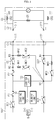
- FIGS. 1 and 2 are diagrams showing a functional configuration of the battery pack 100 according to embodiments of the present disclosure and a charger CS.
- the battery pack 100 includes a battery module B, a first battery contactor BC1, a second battery contactor BC2, a first charging contactor CC1, a second charging contactor CC2, a first measurement resistor MR1, a second measurement resistor MR2, a third measurement resistor MR3, a first power connector C1, a sensing unit 110, a memory unit 120 and a control unit 130.
- the battery module B may include at least one battery cell. If the battery module B includes a plurality of battery cells electrically connected, the plurality of battery cells may be connected to each other in series, in parallel or in series and parallel.
- the battery module B has a positive electrode terminal (+) and a negative electrode terminal (-).
- One end of the first battery contactor BC1 is electrically connected to the positive electrode terminal (+) of the battery module B, and one end of the second battery contactor BC2 is electrically connected to the negative electrode terminal (-) of the battery module B.
- the battery module B may output power or be charged according to a turn-on state or a turn-off state of the first battery contactor BC1 and the second battery contactor BC2.
- the first battery contactor BC1 and the second battery contactor BC2 may be controlled into a turn-on state or a turn-off state by the control unit 130, explained later.
- the turn-on state means a state where a contact point of the contactor is in contact to make one end and the other end of the contactor be electrically connected.
- the turn-off state means a state where the contact point of the contactor is separated to make one end and the other end of the contactor be electrically disconnected.
- One end of the first charging contactor CC1 is electrically connected to the other end of the first battery contactor BC1, and one end of the second charging contactor CC2 is electrically connected to the other end of the second battery contactor BC2.
- first charging contactor CC1 and the second charging contactor CC2 are electrically connected to the first power connector C1, respectively. More specifically, the other end of the first charging contactor CC1 is electrically connected to a first input terminal IT1 provided at the first power connector C1, and the other end of the second charging contactor CC2 is electrically connected to a second input terminal IT2 provided at the first power connector C1.
- a first output terminal OT1 and a second output terminal OT2 of the second power connector C2 may be electrically connected to the first input terminal IT1 and the second input terminal IT2, respectively.
- the first battery contactor BC1 the second battery contactor BC2
- the first charging contactor CC1 and the second charging contactor CC2 are in a turn-on state
- the second power connector C2 is connected to the first power connector C1
- the power of the charger CS is supplied to charge the battery module B.
- a second node N2 and a third node N3 are located at one end and the other end of the first charging contactor CC1, respectively, and a first node N1 and a fourth node N4 are located at one end and the other end of the second charging contactor CC2, respectively.
- the first measurement resistor MR1 is electrically connected between the first node N1 and the second node N2, and the second measurement resistor MR2 is electrically connected between the first node N1 and the third node N3. Also, the third measurement resistor MR3 is electrically connected between the first node N1 and the fourth node N4 and connected to the second charging contactor CC2 in parallel.
- the sensing unit 110 is operatively coupled to the control unit 130. That is, the sensing unit 110 may be connected to the control unit 130 to transmit an electrical signal to the control unit 130 or to receive an electrical signal from the control unit 130.
- the sensing unit 110 measures a battery voltage applied between the positive electrode terminal (+) and the negative electrode terminal (-) of the battery module B according to a preset cycle or the sensing control of the control unit 130.
- the sensing unit 110 measures a first measurement voltage, a second measurement voltage and a third measurement voltage applied to the first measurement resistor MR1, the second measurement resistor MR2 and the third measurement resistor MR3, respectively, according to the preset cycle or the sensing control of the control unit 130.
- the sensing unit 110 measures a charging voltage Vc of the charger CS applied between the first input terminal IT1 and the second input terminal IT2 or between the first output terminal OT1 and the second output terminal OT2 according to the preset cycle or the sensing control of the control unit 130.
- the sensing unit 110 repeatedly measures the battery current flowing into or out of the battery module B.
- the sensing unit 110 may provide the measured signal representing the measured battery voltage, the first measurement voltage, the second measurement voltage, the third measurement voltage, the charging voltage Vc and the battery current to the control unit 130.
- the sensing unit 110 includes a voltage sensor configured to measure the voltage of the battery module B.
- the sensing unit 110 may further include a current sensor configured to measure the current of the battery module B.
- control unit 130 may determine a digital value of each of the measured battery voltage, the first measurement voltage, the second measurement voltage, the third measurement voltage, the charging voltage Vc and the battery current, respectively, and store the digital value in the memory unit 120.
- the memory unit 120 is a semiconductor memory device that records, erases and updates data generated by the control unit 130, and stores a plurality of program codes for diagnosing faults of the first charging contactor CC1 and the second charging contactor CC2, respectively.
- the memory unit 120 may store settings used when the present disclosure is implemented.
- the memory unit 120 is not particularly limited as long as it is a semiconductor memory device known to be capable of recording, erasing and updating data.
- the memory unit 120 may be a DRAM, an SDRAM, a flash memory, a ROM, an EEPROM, a register, or the like.
- the memory unit 120 may further include a storage medium storing program codes that define the control logic of the control unit 130.
- the storage medium includes a non-volatile storage element such as a flash memory or a hard disk.
- the memory unit 120 may be physically separated from the control unit 130 or may be integrated with the control unit 130.
- the control unit 130 determines whether to perform a fault diagnosis of the first charging contactor CC1 and the second charging contactor CC2 based on a diagnosis condition.
- the diagnosis condition may include any one of whether the first power connector C1 and the second power connector C2 are coupled, whether the charging end request signal is received, and whether the first battery contactor BC1 and the second battery contactor BC2 are in a turn-on state.
- the charging end request signal may be a signal output from an ECU of a vehicle including the battery pack according to the present disclosure.
- the control unit 130 determines that the diagnosis condition is satisfied if the first power connector C1 and the second power connector C2 are combined, the charging end request signal is received, and the first battery contactor BC1 and the second battery contactor BC2 are in the turn-on state.
- the control unit 130 outputs an output end signal to the charger CS so that the charging voltage Vc of the charger CS is not applied between the first output terminal OT1 and the second output terminal OT2.
- the control unit 130 checks whether a charge request signal is received and diagnoses a fault of the first charging contactor CC1 and the second charging contactor CC2 just before the battery module B is charged. Namely, the control unit 130 diagnoses whether the first charging contactor CC1 and the second charging contactor CC2 kept in the turn-on state before the battery module B is charged may be controlled into the turn-off state in order to end the charging of the battery module B.
- the control unit 130 determines that the first charging contactor CC1 and the second charging contactor CC2 are to be diagnosed. After that, the control unit 130 controls at least one of the first charging contactor CC1 and the second charging contactor CC2 into a turn-on state or a turn-off state and diagnoses whether a fault occurs at each of the first charging contactor CC1 and the second charging contactor CC2 based on at least one of the first measured voltage, the second measured voltage and the third measured voltage measured according to the above control.
- control unit 130 is configured to generate a control signal for controlling at least one of the first battery contactor BC1, the second battery contactor BC2, the first charging contactor CC1 and the second charging contactor CC2 into a turn-on state or a turn-off state.
- the control unit 130 controls both the first charging contactor CC1 and the second charging contactor CC2 in the turn-on state into the turn-off state. After that, the control unit 130 diagnoses a turn-off fault of the first charging contactor CC1 based on the measured voltage difference between the first measured voltage and the second measured voltage and diagnoses a turn-off fault of the second charging contactor CC2 based on the third measured voltage.
- the turn-off fault may mean a fault that a contactor maintains a turn-on state even though the control unit 130 controls the contactor to turn off.
- control unit 130 may diagnose that a turn-off fault has occurred at the first charging contactor CC1.
- control unit 130 may diagnose that a turn-off fault has not occurred at the first charging contactor CC 1.
- the control unit 130 calculates a theoretical value of the measured voltage difference between the first measured voltage and the second measured voltage corresponding to the case where the connector condition is a first connector condition in which the second power connector C2 having the first output terminal OT1 and the second output terminal OT2 to which the charging voltage Vc is not applied is coupled to the first power connector C1 and the contactor condition is a first contactor condition in which the first battery contactor BC1 and the second battery contactor BC2 are in a turn-on state, the first charging contactor CC1 and the second charging contactor CC2 are in a turn-off state.
- control unit 130 calculates an internal resistance CR1 and insulation resistances CR2, CR3 of the charger CS by using the battery current and the voltage applied between the first input terminal IT1 and the second input terminal IT2, and calculates a theoretical value of the measured voltage difference between the first measured voltage and the second measured voltage in the first connector condition and the first contactor condition by computing a distribution voltage of the charging voltage Vc and a battery voltage between the first measurement resistor MR1, the second measurement resistor MR2, the third measurement resistor MR3, an insulation resistance of the battery pack 100, the internal resistance CR1 of the charger CS and the insulation resistances CR2, CR3.
- control unit 130 calculates a theoretical value of the measured voltage difference between the first measured voltage and the second measured voltage corresponding to the case where the connector condition is a second connector condition in which the second power connector C2 having the first output terminal OT1 and the second output terminal OT2 to which the charging voltage Vc is applied is coupled to the first power connector C1 and the contactor condition is the first contactor condition described above.
- control unit 130 calculates the internal resistance CR1 of the charger CS by using the battery current and the voltage applied between the first input terminal IT1 and the second input terminal IT2, and calculates a theoretical value of the measured voltage difference between the first measured voltage and the second measured voltage in the second connector condition and the first contactor condition by computing a distribution voltage of the charging voltage Vc and a battery voltage between the first measurement resistor MR1, the second measurement resistor MR2, the third measurement resistor MR3, an insulation resistance of the battery pack 100, the internal resistance CR1 of the charger CS and the insulation resistances CR2, CR3.
- control unit 130 sets the first reference voltage to be lower than the calculated theoretical value of the measured voltage difference between the first measured voltage and the second measured voltage.
- control unit 130 sets the first reference voltage corresponding to the insulation resistance of the battery pack 100 and the internal resistance CR1 and the insulation resistances CR2, CR3 of the charger CS connected to the battery pack 100, thereby diagnosing a failure of the first charging contactor CC1 accurately.
- control unit 130 If a turn-off fault of the first charging contactor CC1 is diagnosed, the control unit 130 outputs a fault signal to notify the turn-off fault of the first charging contactor CC1 to the outside.
- control unit 130 may diagnose that a turn-off fault has occurred at the second charging contactor CC2.
- control unit 130 may diagnose that a turn-off fault has not occurred at the second charging contactor CC2.
- control unit 130 calculates a theoretical value of the third measured voltage corresponding to the case where that the connector condition is the first connector condition described above and the contactor condition is the first contactor condition described above.
- control unit 130 calculates the internal resistance CR1 and the insulation resistances CR2, CR3 of the charger CS by using the battery current and the voltage applied between the first input terminal IT1 and the second input terminal IT2, and calculates a theoretical value of the third measured voltage in the first connector condition and the first contactor condition by computing a distribution voltage of the charging voltage Vc and a battery voltage between the first measurement resistor MR1, the second measurement resistor MR2, the third measurement resistor MR3, an insulation resistance of the battery pack 100, the internal resistance CR1 of the charger CS and the insulation resistances CR2, CR3.
- control unit 130 calculates a theoretical value of the third measured voltage corresponding to the case where the connector condition is the second connector condition described above and the contactor condition corresponds to the first contactor condition described above.
- control unit 130 calculates the internal resistance CR1 and the insulation resistances CR2, CR3 of the charger CS by using the battery current and the voltage applied between the first input terminal IT1 and the second input terminal IT2, and calculates a theoretical value of the third measured voltage in the second connector condition and the first contactor condition by computing a distribution voltage of the charging voltage Vc and a battery voltage between the first measurement resistor MR1, the second measurement resistor MR2, the third measurement resistor MR3, an insulation resistance of the battery pack 100, the internal resistance CR1 of the charger CS and the insulation resistances CR2, CR3.
- control unit 130 sets the second reference voltage to be lower than the calculated theoretical value of the third measured voltage.
- control unit 130 sets the second reference voltage corresponding to the insulation resistance of the battery pack 100 and the internal resistance CR1 and the insulation resistances CR2, CR3 of the charger CS connected to the battery pack 100, thereby accurately diagnosing a fault of the second charging contactor CC2.
- control unit 130 If it is diagnosed that a turn-off fault occurs at the second charging contactor CC2, the control unit 130 outputs a fault signal to notify the turn-off fault of the second charging contactor CC2 to the outside.
- control unit 130 may selectively include a processor, an application-specific integrated circuit (ASIC), another chipset, a logic circuit, a register, a communication modem, a data processing device or the like in order to execute various control logics. At least one of the various control logics executable by the control unit 130 may be combined, and the combined control logic is written in a computer-readable code system and recorded on a computer-readable recording medium.
- the recording medium has no limitation as long as it can be accessed by the processor included in a computer.
- the recording medium includes at least one selected from the group consisting of a ROM, a RAM, a register, a CD-ROM, a magnetic tape, a hard disk, a floppy disk and an optical data recording device.
- a battery pack 100' according to another embodiment of the present disclosure will be described.
- some components may be further included and some components may have different functions, compared to the battery pack 100 according to the former embodiment of the present disclosure. Accordingly, the same features will not be described again.
- FIG. 3 is a diagram showing a functional configuration of the battery pack 100' according to another embodiment of the present disclosure in a state where the battery pack 100' is coupled to a charger CS
- FIG. 4 is a diagram showing a functional configuration of the battery pack 100' according to another embodiment of the present disclosure in a state where the battery pack 100' is separated from the charger CS.
- the battery pack 100' may further include a first measurement contactor MC1, a second measurement contactor MC2 and a third measurement contactor MC3, compared to the battery pack 100 according to the former embodiment of the present disclosure.
- the first measurement contactor MC1 is electrically connected between the first measurement resistor MR1 and the first node N1. More specifically, one end of the first measurement resistor MR1 is electrically connected to the second node N2, and the other end of the first measurement resistor MR1 is electrically connected to one end of the first measurement contactor MC1. Subsequently, the other end of the first measurement contactor MC1 is electrically connected to the first node N1. That is, the first measurement resistor MR1 and the first measurement contactor MC1 are electrically connected in series between the first node N1 and the second node N2.
- the second measurement contactor MC2 is electrically connected between the second measurement resistor MR2 and the first node N1. More specifically, one end of the second measurement resistor MR2 is electrically connected to the third node N3, and the other end of the second measurement resistor MR2 is electrically connected to one end of the second measurement contactor MC2. Subsequently, the other end of the second measurement contactor MC2 is electrically connected to the first node N1. That is, the second measurement resistor MR2 and the second measurement contactor MC2 are electrically connected in series between the first node N1 and the third node N3.
- the third measurement contactor MC3 is electrically connected between the third measurement resistor MR3 and the first node N1. More specifically, one end of the third measurement resistor MR3 is electrically connected to the fourth node N4, and the other end of the third measurement resistor MR3 is electrically connected to one end of the third measurement contactor MC3. Subsequently, the other end of the third measurement contactor MC3 is electrically connected to the first node N1. That is, the third measurement resistor MR3 and the third measurement contactor MC3 are electrically connected in series between the first node N1 and the fourth node N4.
- the measurement resistors MR1, ..., MR3 described above may be resistors used to measure the voltage applied to the first charging contactor CC1 and the second charging contactor CC2.
- the measurement contactors MC1, ..., MC3 electrically connected to the measurement resistors may serve to conduct or interrupt the current flowing through the measurement resistors.
- the control unit 130 controls an operation state of at least one of the first measurement contactor MC1, the second measurement contactor MC2 and the third measurement contactor MC3 based on whether at least one of a charging start request signal and a charging end request signal is received.
- the charging start request signal and the charging end request signal may be signals output from an ECU of a vehicle that includes the battery pack according to the present disclosure.
- the first power connector C1 and the second power connector C2 of the charger CS may be in a coupled state in order to initiate charging.
- the control unit 130 controls the operation states of the first measurement contactor MC1, the second measurement contactor MC2 and the third measurement contactor MC3 to turn on. After that, the control unit 130 controls the operating states of the first charging contactor CC1 and the second charging contactor CC2 to turn on.
- the control unit 130 controls the operation states of the first measurement contactor MC1, the second measurement contactor MC2 and the third measurement contactor MC3 to turn on before the operation states of the first charging contactor CC1 and the second charging contactor CC2 come into the turn-on state.
- control unit 130 may monitor the voltage applied to the first charging contactor CC1 and the second charging contactor CC2 before a charging current is applied from the charger CS to the first charging contactor CC1 and the second charging contactor CC2.
- charging may be completed so that the first power connector C1 and the second power connector C2 of the charger CS may be in a state just before being separated.
- the control unit 130 receives firstly controls the operation state of the first charging contactor CC1 to turn off. After that, the control unit 130 controls the operation states of the first measurement contactor and the second measurement contactor based on a measurement voltage difference between the first measurement voltage and the second measurement voltage applied to the first measurement resistor MR1 and the second measurement resistor MR2, respectively.
- the control unit 130 controls the operation states of the first measurement contactor MC1 and the second measurement contactor MC2 to turn off.
- the control unit 130 controls the operation state of the first charging contactor CC1 to turn off, and if the operation state of the first charging contactor CC1 is controlled to turn off, the control unit 130 controls the operation states of the first measurement contactor MC1 and the second measurement contactor MC2 to turn off.
- control unit 130 may control only the operation state of the second measurement contactor MC2 to turn off.
- the control unit 130 may control the operation states of the first measurement contactor MC1 and the second measurement contactor MC2 to turn off so that no voltage is applied to the first input terminal IT1, thereby preventing a user from being electrically shocked by the first input terminal IT1 that may be exposed to the outside during the charging process.
- the control unit 130 firstly controls the operation state of the second charging contactor CC2 to turn off. After that, the control unit 130 controls the operation state of the third measurement contactor MC3 based on the third measurement voltage applied to the third measurement resistor.
- control unit 130 controls the operation state of the third measurement contactor MC3 to turn off.
- the control unit 130 controls the operation state of the second charging contactor CC2 to turn off, and if the operation state of the second charging contactor CC2 is controlled to turn off, the control unit 130 controls the operation state of the third measurement contactor MC3 to turn off .
- control unit 130 may control the operation state of the third measurement contactor MC3 to turn off so that no voltage is applied to the second input terminal IT2, thereby preventing a user from being electrically shocked by the second input terminal IT2 that may be exposed to the outside during the charging process.
- a battery pack 100" according to still another embodiment of the present disclosure will be described.
- some components may be further included and some components may have different functions, compared to the battery pack 100' according to the former embodiment of the present disclosure. Accordingly, the same features will not be described again.
- FIG. 5 is a diagram showing a functional configuration of the battery pack 100" according to still another embodiment of the present disclosure in a state where the battery pack 100" is coupled to a charger CS
- FIG. 6 is a diagram showing a functional configuration of the battery pack 100" according to still another embodiment of the present disclosure in a state where the battery pack 100" is separated from the charger CS.
- the battery pack 100" may further include an illumination intensity sensing unit 140, compared to the battery pack 100' according to the former embodiment of the present disclosure.
- the illumination intensity sensing unit 140 is installed at an inner side of the first power connector C1 to sense an illumination intensity around the first power connector C1.
- the illumination intensity sensing unit 140 is installed on a surface of the first power connector C1 inside the space sealed by the first power connector C1 and the second power connector C2 of the charger CS.
- the first power connector C1 may include a connector cover.
- the illumination intensity sensing unit 140 is installed on the surface of the first power connector C1 inside the inner space of the first power connector C1 and the space sealed by the connector cover.
- the illumination intensity sensing unit 140 may be located in a sealed space into which no light is introduced, as shown in FIG. 5 .
- control unit 130 compares the illumination intensity around the first power connector C1 measured by the illumination intensity sensing unit 140 with a preset reference illumination intensity, and controls the operation state of at least one of the first measurement contactor MC1, the second measurement contactor MC2 and the third measurement contactor MC3 based on the comparison result.
- the preset reference illumination intensity may be an illumination intensity value for determining whether the first input terminal IT1 and the second input terminal IT2 of the first power connector C1 are exposed to the outside.
- the control unit 130 determines that the first power connector C1 is separated from the second power connector C2 of the charger CS or the connector cover of the first power connector C1 is opened.
- the control unit 130 determines that the first input terminal IT1 and the second input terminal IT2 of the first power connector C1 are exposed to the outside .
- the control unit 130 determines that the first power connector C1 is coupled to the second power connector C2 of the charger CS or the connector cover of the first power connector C1 is closed.
- the control unit 130 determines that the first input terminal IT1 and the second input terminal IT2 of the first power connector C1 are not exposed to the outside.
- the control unit 130 controls the operation states of the first measurement contactor MC1, the second measurement contactor MC2 and the third measurement contactor MC3 to turn off.
- control unit 130 controls the operation states of the first charging contactor CC1 and the second charging contactor CC2 to turn off.
- the control unit 130 controls the operation states of the first measurement contactor MC1, the second measurement contactor MC2 and the third measurement contactor MC3 to turn off, thereby preventing an accident that a user is electrically shocked by the first input terminal IT1 or the second input terminal IT2 exposed to the outside.
- a vehicle according to the present disclosure may include the battery pack according to the present disclosure described above.
Abstract
Description
- The present application claims priority to Korean Patent Application No.
10-2017-0162224 filed on November 29, 2017 - The present disclosure relates to a battery pack, and more particularly, to a battery pack for diagnosing a fault of a charging contactor based on a voltage applied to a measurement resistor connected to the charging contactor.
- Recently, the demand for portable electronic products such as notebook computers, video cameras and portable telephones has increased sharply, and electric vehicles, energy storage batteries, robots, satellites and the like have been developed in earnest. Accordingly, high-performance secondary batteries allowing repeated charging and discharging are being actively studied.
- Secondary batteries commercially available at present include nickel-cadmium batteries, nickel hydrogen batteries, nickel-zinc batteries, lithium secondary batteries and the like. Among them, the lithium secondary batteries are in the limelight since they have almost no memory effect compared to nickel-based secondary batteries and also have very low self-discharging rate and high energy density.
- In particular, the battery pack includes a battery module in which a plurality of battery cells are electrically connected, thereby meeting a high-capacity and high-power design required for an electric vehicle. The battery pack applied to an electric vehicle may be electrically connected to a charger of a charging station to charge the electric power.
- To this end, the battery pack applied to an electric vehicle may include a battery contactor connected to a positive electrode terminal and a negative electrode terminal of the battery module to control the electrical connection of the output terminals of the battery module, and a charging contactor for controlling the electrical connection between the battery contactor and a charging terminal to which the power of the charger is input.
- In particular, it is important that the charging contactor is exposed to the outside and also controls the electrical connection of an input terminal connected to a power connector of the charger in order to monitor whether the charging contactor is currently in a turn-on state or a turn-off state and to diagnose whether the charging contactor is actually controlled in response to the control to the turn-on state or the turn-off state.
- The present disclosure is directed to providing a battery pack, which may diagnoses a fault of each of a first charging contactor and a second charging contactor by simultaneously controlling the first charging contactor and the second charging contactor, when a first power connector of the battery pack is connected to a second power connector of a charger and a charging end request signal is received.
- These and other objects and advantages of the present disclosure may be understood from the following detailed description and will become more fully apparent from the exemplary embodiments of the present disclosure. Also, it will be easily understood that the objects and advantages of the present disclosure may be realized by the means shown in the appended claims and combinations thereof.
- In one aspect of the present disclosure, there is provided a battery pack, comprising: a first battery contactor and a second battery contactor respectively having one end electrically connected to a positive electrode terminal and a negative electrode terminal of a battery; a first charging contactor and a second charging contactor respectively having one end electrically connected to the other end of the first battery contactor and the other end of the second battery contactor; a first measurement resistor, a second measurement resistor and a third measurement resistor electrically connected between a first node located at one end of the second charging contactor and a second node located at one end of the first charging contactor, between the first node and a third node located at the other end of the first charging contactor, and between the first node and a fourth node located at the other end of the second charging contactor, respectively; a first power connector having a first input terminal and a second input terminal electrically connected to the other end of the first charging contactor and the other end of the second charging contactor, respectively; and a control unit configured to, when a second power connector of a charger having a first output terminal and a second output terminal respectively electrically connected to the first input terminal and the second input terminal is connected to the first power connector and a charging end request signal is received, simultaneously controlling the first charging contactor and the second charging contactor into a turn-on state or a turn-off state, and diagnosing a fault of each of the first charging contactor and the second charging contactor based on at least one of a first measured voltage, a second measured voltage and a third measured voltage respectively applied to the first measurement resistor, the second measurement resistor and the third measurement resistor.
- Preferably, the control unit may control the first charging contactor and the second charging contactor in a turn-on state into a turn-off state and diagnose a fault of the first charging contactor and the second charging contactor.
- Preferably, the control unit may diagnose a turn-off fault of the second charging contactor based on the third measured voltage and diagnose a turn-off fault of the first charging contactor based on a measured voltage difference between the first measured voltage and the second measured voltage.
- Preferably, when the third measured voltage is lower than a second reference voltage, the control unit may diagnose that a turn-off fault occurs at the second charging contactor.
- Preferably, when the measured voltage difference between the first measured voltage and the second measured voltage is smaller than a first reference voltage, the control unit may diagnose that a turn-off fault occurs at the first charging contactor.
- Preferably, when it is diagnosed that a fault occurs in at least one of the first charging contactor and the second charging connector, the control unit may output a fault signal.
- In another aspect of the present disclosure, there is also provided a vehicle, which may comprise the battery pack.
- According to at least one of embodiments of the present disclosure, it is possible to prevent an electric accident, which may occur since each of the first charging contactor and the second charging contactor maintains its turn-on state after the charging is completed, by diagnosing a turn-off fault of each of the first charging contactor and the second charging contactor and notifying the diagnosing result to the outside.
- The effects of the present disclosure are not limited to the above, and other effects not mentioned herein may be clearly understood by those skilled in the art from the appended claims.
- The accompanying drawings illustrate a preferred embodiment of the present disclosure and together with the foregoing disclosure, serve to provide further understanding of the technical features of the present disclosure, and thus, the present disclosure is not construed as being limited to the drawing.
-
FIGS. 1 and2 are diagrams showing a functional configuration of a battery pack according to embodiments of the present disclosure and an external device. -
FIG. 3 is a diagram showing a functional configuration of a battery pack according to another embodiment of the present disclosure in a state where the battery pack is coupled to a charger. -
FIG. 4 is a diagram showing a functional configuration of the battery pack according to another embodiment of the present disclosure in a state where the battery pack is separated from the charger. -
FIG. 5 is a diagram showing a functional configuration of a battery pack according to still another embodiment of the present disclosure in a state where the battery pack is coupled to a charger. -
FIG. 6 is a diagram showing a functional configuration of the battery pack according to still another embodiment of the present disclosure in a state where the battery pack is separated from the charger. - Hereinafter, preferred embodiments of the present disclosure will be described in detail with reference to the accompanying drawings. Prior to the description, it should be understood that the terms used in the specification and the appended claims should not be construed as limited to general and dictionary meanings, but interpreted based on the meanings and concepts corresponding to technical aspects of the present disclosure on the basis of the principle that the inventor is allowed to define terms appropriately for the best explanation.
- Therefore, the description proposed herein is just a preferable example for the purpose of illustrations only, not intended to limit the scope of the disclosure, so it should be understood that other equivalents and modifications could be made thereto without departing from the scope of the disclosure.
- Additionally, in describing the present disclosure, when it is deemed that a detailed description of relevant known elements or functions renders the key subject matter of the present disclosure ambiguous, the detailed description is omitted herein.
- The terms including the ordinal number such as "first", "second" and the like, may be used to distinguish one element from another among various elements, but not intended to limit the elements by the terms.
- Throughout the specification, when a portion is referred to as "comprising" or "including" any element, it means that the portion may include other elements further, without excluding other elements, unless specifically stated otherwise. Furthermore, the term "control unit" described in the specification refers to a unit that processes at least one function or operation, and may be implemented by hardware, software, or a combination of hardware and software.
- In addition, throughout the specification, when a portion is referred to as being "connected" to another portion, it is not limited to the case that they are "directly connected", but it also includes the case where they are "indirectly connected" with another element being interposed between them.
- Hereinafter, a
battery pack 100 device according to an embodiment of the present disclosure will be described. -
FIGS. 1 and2 are diagrams showing a functional configuration of thebattery pack 100 according to embodiments of the present disclosure and a charger CS. - First, referring to
FIG. 1 , thebattery pack 100 includes a battery module B, a first battery contactor BC1, a second battery contactor BC2, a first charging contactor CC1, a second charging contactor CC2, a first measurement resistor MR1, a second measurement resistor MR2, a third measurement resistor MR3, a first power connector C1, asensing unit 110, amemory unit 120 and acontrol unit 130. - The battery module B may include at least one battery cell. If the battery module B includes a plurality of battery cells electrically connected, the plurality of battery cells may be connected to each other in series, in parallel or in series and parallel. The battery module B has a positive electrode terminal (+) and a negative electrode terminal (-).
- One end of the first battery contactor BC1 is electrically connected to the positive electrode terminal (+) of the battery module B, and one end of the second battery contactor BC2 is electrically connected to the negative electrode terminal (-) of the battery module B.
- By doing so, the battery module B may output power or be charged according to a turn-on state or a turn-off state of the first battery contactor BC1 and the second battery contactor BC2.
- The first battery contactor BC1 and the second battery contactor BC2 may be controlled into a turn-on state or a turn-off state by the
control unit 130, explained later. - Here, the turn-on state means a state where a contact point of the contactor is in contact to make one end and the other end of the contactor be electrically connected. Also, the turn-off state means a state where the contact point of the contactor is separated to make one end and the other end of the contactor be electrically disconnected.
- One end of the first charging contactor CC1 is electrically connected to the other end of the first battery contactor BC1, and one end of the second charging contactor CC2 is electrically connected to the other end of the second battery contactor BC2.
- In addition, the other ends of the first charging contactor CC1 and the second charging contactor CC2 are electrically connected to the first power connector C1, respectively. More specifically, the other end of the first charging contactor CC1 is electrically connected to a first input terminal IT1 provided at the first power connector C1, and the other end of the second charging contactor CC2 is electrically connected to a second input terminal IT2 provided at the first power connector C1.
- Meanwhile, if a second power connector C2 of the charger CS is connected to the first power connector C1, a first output terminal OT1 and a second output terminal OT2 of the second power connector C2 may be electrically connected to the first input terminal IT1 and the second input terminal IT2, respectively.
- Accordingly, when the first battery contactor BC1, the second battery contactor BC2, the first charging contactor CC1 and the second charging contactor CC2 are in a turn-on state, if the second power connector C2 is connected to the first power connector C1, the power of the charger CS is supplied to charge the battery module B.
- Meanwhile, a second node N2 and a third node N3 are located at one end and the other end of the first charging contactor CC1, respectively, and a first node N1 and a fourth node N4 are located at one end and the other end of the second charging contactor CC2, respectively.
- At this time, the first measurement resistor MR1 is electrically connected between the first node N1 and the second node N2, and the second measurement resistor MR2 is electrically connected between the first node N1 and the third node N3. Also, the third measurement resistor MR3 is electrically connected between the first node N1 and the fourth node N4 and connected to the second charging contactor CC2 in parallel.
- The
sensing unit 110 is operatively coupled to thecontrol unit 130. That is, thesensing unit 110 may be connected to thecontrol unit 130 to transmit an electrical signal to thecontrol unit 130 or to receive an electrical signal from thecontrol unit 130. - The
sensing unit 110 measures a battery voltage applied between the positive electrode terminal (+) and the negative electrode terminal (-) of the battery module B according to a preset cycle or the sensing control of thecontrol unit 130. - Also, the
sensing unit 110 measures a first measurement voltage, a second measurement voltage and a third measurement voltage applied to the first measurement resistor MR1, the second measurement resistor MR2 and the third measurement resistor MR3, respectively, according to the preset cycle or the sensing control of thecontrol unit 130. - In addition, the
sensing unit 110 measures a charging voltage Vc of the charger CS applied between the first input terminal IT1 and the second input terminal IT2 or between the first output terminal OT1 and the second output terminal OT2 according to the preset cycle or the sensing control of thecontrol unit 130. - Also, the
sensing unit 110 repeatedly measures the battery current flowing into or out of the battery module B. - After that, the
sensing unit 110 may provide the measured signal representing the measured battery voltage, the first measurement voltage, the second measurement voltage, the third measurement voltage, the charging voltage Vc and the battery current to thecontrol unit 130. - To this end, the
sensing unit 110 includes a voltage sensor configured to measure the voltage of the battery module B. In addition, thesensing unit 110 may further include a current sensor configured to measure the current of the battery module B. - If the measured signal is received from the
sensing unit 110, thecontrol unit 130 may determine a digital value of each of the measured battery voltage, the first measurement voltage, the second measurement voltage, the third measurement voltage, the charging voltage Vc and the battery current, respectively, and store the digital value in thememory unit 120. - The
memory unit 120 is a semiconductor memory device that records, erases and updates data generated by thecontrol unit 130, and stores a plurality of program codes for diagnosing faults of the first charging contactor CC1 and the second charging contactor CC2, respectively. In addition, thememory unit 120 may store settings used when the present disclosure is implemented. - The
memory unit 120 is not particularly limited as long as it is a semiconductor memory device known to be capable of recording, erasing and updating data. As one example, thememory unit 120 may be a DRAM, an SDRAM, a flash memory, a ROM, an EEPROM, a register, or the like. Thememory unit 120 may further include a storage medium storing program codes that define the control logic of thecontrol unit 130. The storage medium includes a non-volatile storage element such as a flash memory or a hard disk. Thememory unit 120 may be physically separated from thecontrol unit 130 or may be integrated with thecontrol unit 130. - The
control unit 130 determines whether to perform a fault diagnosis of the first charging contactor CC1 and the second charging contactor CC2 based on a diagnosis condition. - Here, the diagnosis condition may include any one of whether the first power connector C1 and the second power connector C2 are coupled, whether the charging end request signal is received, and whether the first battery contactor BC1 and the second battery contactor BC2 are in a turn-on state.
- Here, the charging end request signal may be a signal output from an ECU of a vehicle including the battery pack according to the present disclosure.
- As shown in
FIG. 2 , thecontrol unit 130 according to an embodiment determines that the diagnosis condition is satisfied if the first power connector C1 and the second power connector C2 are combined, the charging end request signal is received, and the first battery contactor BC1 and the second battery contactor BC2 are in the turn-on state. - Meanwhile, if the charging end request signal is received, the
control unit 130 outputs an output end signal to the charger CS so that the charging voltage Vc of the charger CS is not applied between the first output terminal OT1 and the second output terminal OT2. - The
control unit 130 checks whether a charge request signal is received and diagnoses a fault of the first charging contactor CC1 and the second charging contactor CC2 just before the battery module B is charged. Namely, thecontrol unit 130 diagnoses whether the first charging contactor CC1 and the second charging contactor CC2 kept in the turn-on state before the battery module B is charged may be controlled into the turn-off state in order to end the charging of the battery module B. - If the diagnosis condition is satisfied, the
control unit 130 determines that the first charging contactor CC1 and the second charging contactor CC2 are to be diagnosed. After that, thecontrol unit 130 controls at least one of the first charging contactor CC1 and the second charging contactor CC2 into a turn-on state or a turn-off state and diagnoses whether a fault occurs at each of the first charging contactor CC1 and the second charging contactor CC2 based on at least one of the first measured voltage, the second measured voltage and the third measured voltage measured according to the above control. - To this end, the
control unit 130 is configured to generate a control signal for controlling at least one of the first battery contactor BC1, the second battery contactor BC2, the first charging contactor CC1 and the second charging contactor CC2 into a turn-on state or a turn-off state. - First, as shown in
FIG. 2 , thecontrol unit 130 controls both the first charging contactor CC1 and the second charging contactor CC2 in the turn-on state into the turn-off state. After that, thecontrol unit 130 diagnoses a turn-off fault of the first charging contactor CC1 based on the measured voltage difference between the first measured voltage and the second measured voltage and diagnoses a turn-off fault of the second charging contactor CC2 based on the third measured voltage. - Here, the turn-off fault may mean a fault that a contactor maintains a turn-on state even though the
control unit 130 controls the contactor to turn off. - First, if the measured voltage difference is lower than a first reference voltage, the
control unit 130 may diagnose that a turn-off fault has occurred at the first charging contactor CC1. - Conversely, if the measured voltage difference is equal to or higher than the first reference voltage, the
control unit 130 may diagnose that a turn-off fault has not occurred at the firstcharging contactor CC 1. - At this time, the
control unit 130 calculates a theoretical value of the measured voltage difference between the first measured voltage and the second measured voltage corresponding to the case where the connector condition is a first connector condition in which the second power connector C2 having the first output terminal OT1 and the second output terminal OT2 to which the charging voltage Vc is not applied is coupled to the first power connector C1 and the contactor condition is a first contactor condition in which the first battery contactor BC1 and the second battery contactor BC2 are in a turn-on state, the first charging contactor CC1 and the second charging contactor CC2 are in a turn-off state. - More specifically, the
control unit 130 calculates an internal resistance CR1 and insulation resistances CR2, CR3 of the charger CS by using the battery current and the voltage applied between the first input terminal IT1 and the second input terminal IT2, and calculates a theoretical value of the measured voltage difference between the first measured voltage and the second measured voltage in the first connector condition and the first contactor condition by computing a distribution voltage of the charging voltage Vc and a battery voltage between the first measurement resistor MR1, the second measurement resistor MR2, the third measurement resistor MR3, an insulation resistance of thebattery pack 100, the internal resistance CR1 of the charger CS and the insulation resistances CR2, CR3. - In addition, the
control unit 130 calculates a theoretical value of the measured voltage difference between the first measured voltage and the second measured voltage corresponding to the case where the connector condition is a second connector condition in which the second power connector C2 having the first output terminal OT1 and the second output terminal OT2 to which the charging voltage Vc is applied is coupled to the first power connector C1 and the contactor condition is the first contactor condition described above. - More specifically, the
control unit 130 calculates the internal resistance CR1 of the charger CS by using the battery current and the voltage applied between the first input terminal IT1 and the second input terminal IT2, and calculates a theoretical value of the measured voltage difference between the first measured voltage and the second measured voltage in the second connector condition and the first contactor condition by computing a distribution voltage of the charging voltage Vc and a battery voltage between the first measurement resistor MR1, the second measurement resistor MR2, the third measurement resistor MR3, an insulation resistance of thebattery pack 100, the internal resistance CR1 of the charger CS and the insulation resistances CR2, CR3. - After that, the
control unit 130 sets the first reference voltage to be lower than the calculated theoretical value of the measured voltage difference between the first measured voltage and the second measured voltage. - By doing so, the
control unit 130 sets the first reference voltage corresponding to the insulation resistance of thebattery pack 100 and the internal resistance CR1 and the insulation resistances CR2, CR3 of the charger CS connected to thebattery pack 100, thereby diagnosing a failure of the first charging contactor CC1 accurately. - If a turn-off fault of the first charging contactor CC1 is diagnosed, the
control unit 130 outputs a fault signal to notify the turn-off fault of the first charging contactor CC1 to the outside. - Meanwhile, if a third measured voltage is lower than the second reference voltage, the
control unit 130 may diagnose that a turn-off fault has occurred at the second charging contactor CC2. - Conversely, if the third measured voltage is equal to or higher than the second reference voltage, the
control unit 130 may diagnose that a turn-off fault has not occurred at the second charging contactor CC2. - At this time, the
control unit 130 calculates a theoretical value of the third measured voltage corresponding to the case where that the connector condition is the first connector condition described above and the contactor condition is the first contactor condition described above. - More specifically, the
control unit 130 calculates the internal resistance CR1 and the insulation resistances CR2, CR3 of the charger CS by using the battery current and the voltage applied between the first input terminal IT1 and the second input terminal IT2, and calculates a theoretical value of the third measured voltage in the first connector condition and the first contactor condition by computing a distribution voltage of the charging voltage Vc and a battery voltage between the first measurement resistor MR1, the second measurement resistor MR2, the third measurement resistor MR3, an insulation resistance of thebattery pack 100, the internal resistance CR1 of the charger CS and the insulation resistances CR2, CR3. - In addition, the
control unit 130 calculates a theoretical value of the third measured voltage corresponding to the case where the connector condition is the second connector condition described above and the contactor condition corresponds to the first contactor condition described above. - More specifically, the
control unit 130 calculates the internal resistance CR1 and the insulation resistances CR2, CR3 of the charger CS by using the battery current and the voltage applied between the first input terminal IT1 and the second input terminal IT2, and calculates a theoretical value of the third measured voltage in the second connector condition and the first contactor condition by computing a distribution voltage of the charging voltage Vc and a battery voltage between the first measurement resistor MR1, the second measurement resistor MR2, the third measurement resistor MR3, an insulation resistance of thebattery pack 100, the internal resistance CR1 of the charger CS and the insulation resistances CR2, CR3. - After that, the
control unit 130 sets the second reference voltage to be lower than the calculated theoretical value of the third measured voltage. - By doing so, the
control unit 130 sets the second reference voltage corresponding to the insulation resistance of thebattery pack 100 and the internal resistance CR1 and the insulation resistances CR2, CR3 of the charger CS connected to thebattery pack 100, thereby accurately diagnosing a fault of the second charging contactor CC2. - If it is diagnosed that a turn-off fault occurs at the second charging contactor CC2, the
control unit 130 outputs a fault signal to notify the turn-off fault of the second charging contactor CC2 to the outside. - Meanwhile, the
control unit 130 may selectively include a processor, an application-specific integrated circuit (ASIC), another chipset, a logic circuit, a register, a communication modem, a data processing device or the like in order to execute various control logics. At least one of the various control logics executable by thecontrol unit 130 may be combined, and the combined control logic is written in a computer-readable code system and recorded on a computer-readable recording medium. The recording medium has no limitation as long as it can be accessed by the processor included in a computer. As one example, the recording medium includes at least one selected from the group consisting of a ROM, a RAM, a register, a CD-ROM, a magnetic tape, a hard disk, a floppy disk and an optical data recording device. - Hereinafter, a battery pack 100' according to another embodiment of the present disclosure will be described. In the battery pack 100' according to another embodiment of the present disclosure, some components may be further included and some components may have different functions, compared to the
battery pack 100 according to the former embodiment of the present disclosure. Accordingly, the same features will not be described again. -
FIG. 3 is a diagram showing a functional configuration of the battery pack 100' according to another embodiment of the present disclosure in a state where the battery pack 100' is coupled to a charger CS, andFIG. 4 is a diagram showing a functional configuration of the battery pack 100' according to another embodiment of the present disclosure in a state where the battery pack 100' is separated from the charger CS. - Referring to
FIG. 3 , the battery pack 100' according to another embodiment of the present disclosure may further include a first measurement contactor MC1, a second measurement contactor MC2 and a third measurement contactor MC3, compared to thebattery pack 100 according to the former embodiment of the present disclosure. - The first measurement contactor MC1 is electrically connected between the first measurement resistor MR1 and the first node N1. More specifically, one end of the first measurement resistor MR1 is electrically connected to the second node N2, and the other end of the first measurement resistor MR1 is electrically connected to one end of the first measurement contactor MC1. Subsequently, the other end of the first measurement contactor MC1 is electrically connected to the first node N1. That is, the first measurement resistor MR1 and the first measurement contactor MC1 are electrically connected in series between the first node N1 and the second node N2.
- The second measurement contactor MC2 is electrically connected between the second measurement resistor MR2 and the first node N1. More specifically, one end of the second measurement resistor MR2 is electrically connected to the third node N3, and the other end of the second measurement resistor MR2 is electrically connected to one end of the second measurement contactor MC2. Subsequently, the other end of the second measurement contactor MC2 is electrically connected to the first node N1. That is, the second measurement resistor MR2 and the second measurement contactor MC2 are electrically connected in series between the first node N1 and the third node N3.
- The third measurement contactor MC3 is electrically connected between the third measurement resistor MR3 and the first node N1. More specifically, one end of the third measurement resistor MR3 is electrically connected to the fourth node N4, and the other end of the third measurement resistor MR3 is electrically connected to one end of the third measurement contactor MC3. Subsequently, the other end of the third measurement contactor MC3 is electrically connected to the first node N1. That is, the third measurement resistor MR3 and the third measurement contactor MC3 are electrically connected in series between the first node N1 and the fourth node N4.
- The measurement resistors MR1, ..., MR3 described above may be resistors used to measure the voltage applied to the first charging contactor CC1 and the second charging contactor CC2. The measurement contactors MC1, ..., MC3 electrically connected to the measurement resistors may serve to conduct or interrupt the current flowing through the measurement resistors.
- The
control unit 130 controls an operation state of at least one of the first measurement contactor MC1, the second measurement contactor MC2 and the third measurement contactor MC3 based on whether at least one of a charging start request signal and a charging end request signal is received. - Here, the charging start request signal and the charging end request signal may be signals output from an ECU of a vehicle that includes the battery pack according to the present disclosure.
- In addition, if the charging start request signal is outputted from the ECU of the vehicle, as shown in
FIG. 3 , the first power connector C1 and the second power connector C2 of the charger CS may be in a coupled state in order to initiate charging. - If the charging start request signal is received, firstly, the
control unit 130 controls the operation states of the first measurement contactor MC1, the second measurement contactor MC2 and the third measurement contactor MC3 to turn on. After that, thecontrol unit 130 controls the operating states of the first charging contactor CC1 and the second charging contactor CC2 to turn on. - That is, if the charging start request signal is received, the
control unit 130 controls the operation states of the first measurement contactor MC1, the second measurement contactor MC2 and the third measurement contactor MC3 to turn on before the operation states of the first charging contactor CC1 and the second charging contactor CC2 come into the turn-on state. - By doing so, the
control unit 130 may monitor the voltage applied to the first charging contactor CC1 and the second charging contactor CC2 before a charging current is applied from the charger CS to the first charging contactor CC1 and the second charging contactor CC2. - Meanwhile, if the charging end request signal is output from an ECU of a vehicle, charging may be completed so that the first power connector C1 and the second power connector C2 of the charger CS may be in a state just before being separated.
- Accordingly, if the charging end request signal is received, the
control unit 130 receives firstly controls the operation state of the first charging contactor CC1 to turn off. After that, thecontrol unit 130 controls the operation states of the first measurement contactor and the second measurement contactor based on a measurement voltage difference between the first measurement voltage and the second measurement voltage applied to the first measurement resistor MR1 and the second measurement resistor MR2, respectively. - More specifically, if the measurement voltage difference between the first measurement voltage and the second measurement voltage is equal to or greater than a preset first control voltage, the
control unit 130 controls the operation states of the first measurement contactor MC1 and the second measurement contactor MC2 to turn off. - That is, if the charging end request signal is received, the
control unit 130 controls the operation state of the first charging contactor CC1 to turn off, and if the operation state of the first charging contactor CC1 is controlled to turn off, thecontrol unit 130 controls the operation states of the first measurement contactor MC1 and the second measurement contactor MC2 to turn off. - At this time, if the measurement voltage difference between the first measurement voltage and the second measurement voltage is equal to or greater than the preset first control voltage, the
control unit 130 may control only the operation state of the second measurement contactor MC2 to turn off. - In this way, if the first power connector is separated from the second power connector of the charger as the
control unit 130 completes charging as shown inFIG. 4 , thecontrol unit 130 may control the operation states of the first measurement contactor MC1 and the second measurement contactor MC2 to turn off so that no voltage is applied to the first input terminal IT1, thereby preventing a user from being electrically shocked by the first input terminal IT1 that may be exposed to the outside during the charging process. - Meanwhile, if the charging end request signal is received, the
control unit 130 firstly controls the operation state of the second charging contactor CC2 to turn off. After that, thecontrol unit 130 controls the operation state of the third measurement contactor MC3 based on the third measurement voltage applied to the third measurement resistor. - More specifically, if the third measurement voltage is equal to or greater than the preset second control voltage, the
control unit 130 controls the operation state of the third measurement contactor MC3 to turn off. - That is, if the charging end request signal is received, the
control unit 130 controls the operation state of the second charging contactor CC2 to turn off, and if the operation state of the second charging contactor CC2 is controlled to turn off, thecontrol unit 130 controls the operation state of the third measurement contactor MC3 to turn off . - In this way, if the first power connector is separated from the second power connector of the charger as the
control unit 130 completes charging as shown inFIG. 4 , thecontrol unit 130 may control the operation state of the third measurement contactor MC3 to turn off so that no voltage is applied to the second input terminal IT2, thereby preventing a user from being electrically shocked by the second input terminal IT2 that may be exposed to the outside during the charging process. - Hereinafter, a
battery pack 100" according to still another embodiment of the present disclosure will be described. In thebattery pack 100" according to still another embodiment of the present disclosure, some components may be further included and some components may have different functions, compared to the battery pack 100' according to the former embodiment of the present disclosure. Accordingly, the same features will not be described again. -
FIG. 5 is a diagram showing a functional configuration of thebattery pack 100" according to still another embodiment of the present disclosure in a state where thebattery pack 100" is coupled to a charger CS, andFIG. 6 is a diagram showing a functional configuration of thebattery pack 100" according to still another embodiment of the present disclosure in a state where thebattery pack 100" is separated from the charger CS. - Referring to
FIGS. 5 and6 , thebattery pack 100" according to still another embodiment of the present disclosure may further include an illuminationintensity sensing unit 140, compared to the battery pack 100' according to the former embodiment of the present disclosure. - The illumination
intensity sensing unit 140 is installed at an inner side of the first power connector C1 to sense an illumination intensity around the first power connector C1. - More specifically, if the first power connector C1 and the second power connector C2 of the charger CS are coupled, the illumination
intensity sensing unit 140 is installed on a surface of the first power connector C1 inside the space sealed by the first power connector C1 and the second power connector C2 of the charger CS. - Meanwhile, the first power connector C1 may include a connector cover.
- At this time, if the connector cover is closed, the illumination
intensity sensing unit 140 is installed on the surface of the first power connector C1 inside the inner space of the first power connector C1 and the space sealed by the connector cover. - That is, if the first power connector C1 is coupled to the second power connector C2 of the charger CS or the connector cover of the first power connector C1 is closed, the illumination
intensity sensing unit 140 may be located in a sealed space into which no light is introduced, as shown inFIG. 5 . - By using this, the
control unit 130 compares the illumination intensity around the first power connector C1 measured by the illuminationintensity sensing unit 140 with a preset reference illumination intensity, and controls the operation state of at least one of the first measurement contactor MC1, the second measurement contactor MC2 and the third measurement contactor MC3 based on the comparison result. - Here, the preset reference illumination intensity may be an illumination intensity value for determining whether the first input terminal IT1 and the second input terminal IT2 of the first power connector C1 are exposed to the outside.
- More specifically, if the illumination intensity around the first power connector C1 measured by the illumination
intensity sensing unit 140 is equal to or greater than the preset reference illumination intensity, as shown inFIG. 6 , thecontrol unit 130 determines that the first power connector C1 is separated from the second power connector C2 of the charger CS or the connector cover of the first power connector C1 is opened. - That is, if the illumination intensity around the first power connector C1 measured by the illumination
intensity sensing unit 140 is equal to or greater than the preset reference illumination intensity, thecontrol unit 130 determines that the first input terminal IT1 and the second input terminal IT2 of the first power connector C1 are exposed to the outside . - Conversely, if the illumination intensity around the first power connector C1 measured by the illumination
intensity sensing unit 140 is smaller than the preset reference illumination intensity, as shown inFIG. 5 , thecontrol unit 130 determines that the first power connector C1 is coupled to the second power connector C2 of the charger CS or the connector cover of the first power connector C1 is closed. - That is, if the illumination intensity around the first power connector C1 measured by the illumination
intensity sensing unit 140 is smaller than the preset reference illumination intensity, thecontrol unit 130 determines that the first input terminal IT1 and the second input terminal IT2 of the first power connector C1 are not exposed to the outside. - After that, if the illumination intensity around the first power connector C1 measured by the illumination
intensity sensing unit 140 is equal to or greater than the preset reference illumination intensity, thecontrol unit 130 controls the operation states of the first measurement contactor MC1, the second measurement contactor MC2 and the third measurement contactor MC3 to turn off. - In addition, if the illumination intensity around the first power connector C1 measured by the illumination
intensity sensing unit 140 is equal to or greater than the preset reference illumination intensity, thecontrol unit 130 controls the operation states of the first charging contactor CC1 and the second charging contactor CC2 to turn off. - By doing so, if the first input terminal IT1 and the second input terminal IT2 of the first power connector C1 are exposed to the outside, the
control unit 130 controls the operation states of the first measurement contactor MC1, the second measurement contactor MC2 and the third measurement contactor MC3 to turn off, thereby preventing an accident that a user is electrically shocked by the first input terminal IT1 or the second input terminal IT2 exposed to the outside. - Meanwhile, a vehicle according to the present disclosure may include the battery pack according to the present disclosure described above.
- The embodiments of the present disclosure described above are not necessarily implemented by apparatuses and methods but may also be implemented through a program for realizing functions corresponding to the configuration of the present disclosure or a recording medium on which the program is recorded. Such implementation may be easily performed by those skilled in the art from the above description of the embodiments.
- The present disclosure has been described in detail. However, it should be understood that the detailed description and specific examples, while indicating preferred embodiments of the disclosure, are given by way of illustration only, since various changes and modifications within the scope of the disclosure will become apparent to those skilled in the art from this detailed description.
- Additionally, many substitutions, modifications and changes may be made to the present disclosure described hereinabove by those skilled in the art without departing from the technical aspects of the present disclosure, and the present disclosure is not limited to the above-described embodiments and the accompanying drawings, and each embodiment may be selectively combined in part or in whole to allow various modifications.
Claims (7)
- A battery pack, comprising:a first battery contactor and a second battery contactor respectively having one end electrically connected to a positive electrode terminal and a negative electrode terminal of a battery;a first charging contactor and a second charging contactor respectively having one end electrically connected to the other end of the first battery contactor and the other end of the second battery contactor;a first measurement resistor, a second measurement resistor and a third measurement resistor electrically connected between a first node located at one end of the second charging contactor and a second node located at one end of the first charging contactor, between the first node and a third node located at the other end of the first charging contactor, and between the first node and a fourth node located at the other end of the second charging contactor, respectively;a first power connector having a first input terminal and a second input terminal electrically connected to the other end of the first charging contactor and the other end of the second charging contactor, respectively; anda control unit configured to, when a second power connector of a charger having a first output terminal and a second output terminal respectively electrically connected to the first input terminal and the second input terminal is connected to the first power connector and a charging end request signal is received, simultaneously controlling the first charging contactor and the second charging contactor into a turn-on state or a turn-off state, and diagnosing a fault of each of the first charging contactor and the second charging contactor based on at least one of a first measured voltage, a second measured voltage and a third measured voltage respectively applied to the first measurement resistor, the second measurement resistor and the third measurement resistor.
- The battery pack according to claim 1,
wherein the control unit controls the first charging contactor and the second charging contactor in a turn-on state into a turn-off state and diagnoses a fault of the first charging contactor and the second charging contactor. - The battery pack according to claim 2,
wherein the control unit diagnoses a turn-off fault of the second charging contactor based on the third measured voltage and diagnoses a turn-off fault of the first charging contactor based on a measured voltage difference between the first measured voltage and the second measured voltage. - The battery pack according to claim 2,
wherein when the third measured voltage is lower than a second reference voltage, the control unit diagnoses that a turn-off fault occurs at the second charging contactor. - The battery pack according to claim 2,
wherein when the measured voltage difference between the first measured voltage and the second measured voltage is smaller than a first reference voltage, the control unit diagnoses that a turn-off fault occurs at the first charging contactor. - The battery pack according to claim 1,
wherein when it is diagnosed that a fault occurs in at least one of the first charging contactor and the second charging connector, the control unit outputs a fault signal. - A vehicle, comprising a battery pack according to any one of claims 1 to 6.
Priority Applications (1)
| Application Number | Priority Date | Filing Date | Title |
|---|---|---|---|
| PL18883138T PL3654440T3 (en) | 2017-11-29 | 2018-11-29 | Battery pack |
Applications Claiming Priority (2)
| Application Number | Priority Date | Filing Date | Title |
|---|---|---|---|
| KR1020170162224A KR102256598B1 (en) | 2017-11-29 | 2017-11-29 | Battery back |
| PCT/KR2018/014979 WO2019107978A1 (en) | 2017-11-29 | 2018-11-29 | Battery pack |
Publications (3)
| Publication Number | Publication Date |
|---|---|
| EP3654440A1 true EP3654440A1 (en) | 2020-05-20 |
| EP3654440A4 EP3654440A4 (en) | 2020-06-03 |
| EP3654440B1 EP3654440B1 (en) | 2021-11-03 |
Family
ID=66664138
Family Applications (1)
| Application Number | Title | Priority Date | Filing Date |
|---|---|---|---|
| EP18883138.2A Active EP3654440B1 (en) | 2017-11-29 | 2018-11-29 | Battery pack |
Country Status (7)
| Country | Link |
|---|---|
| US (1) | US11467212B2 (en) |
| EP (1) | EP3654440B1 (en) |
| JP (1) | JP7014381B2 (en) |
| KR (1) | KR102256598B1 (en) |
| CN (1) | CN110679031B (en) |
| PL (1) | PL3654440T3 (en) |
| WO (1) | WO2019107978A1 (en) |
Families Citing this family (3)
| Publication number | Priority date | Publication date | Assignee | Title |
|---|---|---|---|---|
| KR102256094B1 (en) * | 2017-11-28 | 2021-05-25 | 주식회사 엘지에너지솔루션 | Battery back |
| KR102256100B1 (en) * | 2017-11-29 | 2021-05-25 | 주식회사 엘지에너지솔루션 | Battery back |
| US11545971B2 (en) * | 2019-12-17 | 2023-01-03 | Analog Devices International Unlimited Company | Aging protection techniques for power switches |
Family Cites Families (37)
| Publication number | Priority date | Publication date | Assignee | Title |
|---|---|---|---|---|
| JP2008005593A (en) | 2006-06-21 | 2008-01-10 | Sony Corp | Battery pack, electronic apparatus, and control method |
| JP2008037211A (en) * | 2006-08-03 | 2008-02-21 | Sanyo Electric Co Ltd | Power supply device for vehicle |
| JP4996190B2 (en) | 2006-09-29 | 2012-08-08 | 矢崎総業株式会社 | Voltage detector |
| JP4942602B2 (en) * | 2007-09-26 | 2012-05-30 | 三洋電機株式会社 | Power supply for vehicle |
| JP4816628B2 (en) | 2007-11-30 | 2011-11-16 | トヨタ自動車株式会社 | Vehicle charging control device |
| JP5224095B2 (en) | 2007-12-27 | 2013-07-03 | 株式会社Gsユアサ | Battery management device for battery pack |
| FR2948461B1 (en) | 2009-07-24 | 2011-07-01 | Renault Sa | METHOD FOR DIAGNOSING THE OPERATION OF A DEVICE FOR CUTTING AND CONNECTING A BATTERY TO A MOTOR VEHICLE EDGE NETWORK |
| JP5450144B2 (en) | 2010-02-10 | 2014-03-26 | 三洋電機株式会社 | Power supply device for vehicle and vehicle equipped with this power supply device |
| JP2012090474A (en) | 2010-10-21 | 2012-05-10 | Hitachi Vehicle Energy Ltd | Battery system |
| JP5733786B2 (en) | 2010-11-02 | 2015-06-10 | Necエナジーデバイス株式会社 | Secondary battery system |
| KR101182890B1 (en) * | 2010-12-01 | 2012-09-13 | 삼성에스디아이 주식회사 | System for controlling charging of battery pack |
| DE102011004516A1 (en) * | 2011-02-22 | 2012-08-23 | Sb Limotive Company Ltd. | Electric circuit for use with lithium ion battery system for diagnosis of switching contacts in battery-powered road vehicle, has unit for generating and measuring voltage drop via resistance element |
| JP5893411B2 (en) | 2012-01-06 | 2016-03-23 | 日置電機株式会社 | Voltage measuring apparatus and voltage measuring method |
| JP5910172B2 (en) | 2012-03-01 | 2016-04-27 | 株式会社Gsユアサ | Switch failure diagnosis device, battery pack, switch failure diagnosis program, switch failure diagnosis method |
| DE102012213159A1 (en) * | 2012-07-26 | 2014-01-30 | Robert Bosch Gmbh | Battery system with battery contactors and a diagnostic device for monitoring the functional status of the contactors and the associated diagnostic procedure |
| JP6024468B2 (en) | 2013-01-17 | 2016-11-16 | 日立金属株式会社 | Vehicle charging device |
| JP2014169933A (en) | 2013-03-04 | 2014-09-18 | Seiko Instruments Inc | Battery device |
| JP6454466B2 (en) | 2013-11-11 | 2019-01-16 | 三菱自動車工業株式会社 | Charge control device |
| KR20150109153A (en) | 2014-03-19 | 2015-10-01 | 엘에스산전 주식회사 | Cable installment type charging control apparatus and method thereof |
| JP2016010263A (en) | 2014-06-25 | 2016-01-18 | トヨタ自動車株式会社 | Power storage system |
| KR101716886B1 (en) * | 2014-11-07 | 2017-03-15 | 주식회사 엘지화학 | Apparatus for Diagnosing Electrical Contactor Capable of Accurately Detecting Diagnosing Voltage |
| JP6589368B2 (en) | 2015-05-20 | 2019-10-16 | 日産自動車株式会社 | Power supply apparatus and diagnostic method for diagnosing abnormality of power supply apparatus |
| JP6503893B2 (en) * | 2015-05-28 | 2019-04-24 | 三菱自動車工業株式会社 | Vehicle charge control device |
| KR101780396B1 (en) * | 2015-06-29 | 2017-09-20 | 주식회사 코캄일렉트로닉스 | Apparatus and method for protecting battery |
| CN105137336B (en) | 2015-07-29 | 2018-07-24 | 南通大学 | Detect the diagnostic method of electric automobile high-voltage relay failure |
| JP2017120191A (en) | 2015-12-28 | 2017-07-06 | 三菱自動車工業株式会社 | Failure determination device |
| KR102065737B1 (en) * | 2016-02-18 | 2020-01-13 | 주식회사 엘지화학 | Charging or discharging system and method for diagnosing state of contactor |
| KR102059076B1 (en) | 2016-02-19 | 2020-02-11 | 주식회사 엘지화학 | Apparatus of Analyzing Malfunction of Switch component and Method Thereof |
| KR102519118B1 (en) | 2016-02-24 | 2023-04-05 | 삼성에스디아이 주식회사 | Battery protection circuit |
| JP6699253B2 (en) | 2016-03-10 | 2020-05-27 | 富士電機株式会社 | Power conversion device, switching element short-circuit failure diagnosis method, and switching element open failure diagnosis method |
| JP2017175790A (en) | 2016-03-24 | 2017-09-28 | 株式会社豊田自動織機 | Charge connector connection detection apparatus |
| JP2017198598A (en) | 2016-04-28 | 2017-11-02 | 矢崎総業株式会社 | Electric charge recovery system and power source recovery method |
| US10877095B2 (en) * | 2016-09-07 | 2020-12-29 | Panasonic Intellectual Property Management Co., Ltd. | Power storage system |
| KR102256094B1 (en) | 2017-11-28 | 2021-05-25 | 주식회사 엘지에너지솔루션 | Battery back |
| KR102256100B1 (en) * | 2017-11-29 | 2021-05-25 | 주식회사 엘지에너지솔루션 | Battery back |
| KR102256097B1 (en) * | 2017-11-29 | 2021-05-25 | 주식회사 엘지에너지솔루션 | Battery back |
| KR102256099B1 (en) * | 2017-11-29 | 2021-05-25 | 주식회사 엘지에너지솔루션 | Battery back |
-
2017
- 2017-11-29 KR KR1020170162224A patent/KR102256598B1/en active IP Right Grant
-
2018
- 2018-11-29 US US16/615,272 patent/US11467212B2/en active Active
- 2018-11-29 CN CN201880031995.4A patent/CN110679031B/en active Active
- 2018-11-29 EP EP18883138.2A patent/EP3654440B1/en active Active
- 2018-11-29 WO PCT/KR2018/014979 patent/WO2019107978A1/en unknown
- 2018-11-29 PL PL18883138T patent/PL3654440T3/en unknown
- 2018-11-29 JP JP2019555821A patent/JP7014381B2/en active Active
Also Published As
| Publication number | Publication date |
|---|---|
| EP3654440A4 (en) | 2020-06-03 |
| CN110679031A (en) | 2020-01-10 |
| KR20190063267A (en) | 2019-06-07 |
| CN110679031B (en) | 2023-01-10 |
| JP7014381B2 (en) | 2022-02-01 |
| US20200174075A1 (en) | 2020-06-04 |
| WO2019107978A1 (en) | 2019-06-06 |
| KR102256598B1 (en) | 2021-05-26 |
| JP2020517067A (en) | 2020-06-11 |
| US11467212B2 (en) | 2022-10-11 |
| PL3654440T3 (en) | 2022-02-28 |
| EP3654440B1 (en) | 2021-11-03 |
Similar Documents
| Publication | Publication Date | Title |
|---|---|---|
| EP3624250B1 (en) | Battery pack | |
| EP3624249B1 (en) | Battery pack | |
| EP3624251B1 (en) | Battery pack | |
| EP3654440B1 (en) | Battery pack | |
| EP3627614B1 (en) | Battery pack | |
| EP3657593B1 (en) | Battery pack |
Legal Events
| Date | Code | Title | Description |
|---|---|---|---|
| STAA | Information on the status of an ep patent application or granted ep patent |
Free format text: STATUS: THE INTERNATIONAL PUBLICATION HAS BEEN MADE |
|
| PUAI | Public reference made under article 153(3) epc to a published international application that has entered the european phase |
Free format text: ORIGINAL CODE: 0009012 |
|
| STAA | Information on the status of an ep patent application or granted ep patent |
Free format text: STATUS: REQUEST FOR EXAMINATION WAS MADE |
|
| 17P | Request for examination filed |
Effective date: 20200213 |
|
| AK | Designated contracting states |
Kind code of ref document: A1 Designated state(s): AL AT BE BG CH CY CZ DE DK EE ES FI FR GB GR HR HU IE IS IT LI LT LU LV MC MK MT NL NO PL PT RO RS SE SI SK SM TR |
|
| AX | Request for extension of the european patent |
Extension state: BA ME |
|
| A4 | Supplementary search report drawn up and despatched |
Effective date: 20200508 |
|
| RIC1 | Information provided on ipc code assigned before grant |
Ipc: H01M 10/42 20060101AFI20200501BHEP Ipc: H01M 10/46 20060101ALI20200501BHEP Ipc: H01M 10/48 20060101ALI20200501BHEP Ipc: H02J 7/00 20060101ALI20200501BHEP Ipc: G01R 31/327 20060101ALI20200501BHEP Ipc: H01M 2/10 20060101ALI20200501BHEP |
|
| STAA | Information on the status of an ep patent application or granted ep patent |
Free format text: STATUS: EXAMINATION IS IN PROGRESS |
|
| 17Q | First examination report despatched |
Effective date: 20201013 |
|
| STAA | Information on the status of an ep patent application or granted ep patent |
Free format text: STATUS: EXAMINATION IS IN PROGRESS |
|
| DAV | Request for validation of the european patent (deleted) | ||
| DAX | Request for extension of the european patent (deleted) | ||
| REG | Reference to a national code |
Ref country code: DE Ref legal event code: R079 Ref document number: 602018026278 Country of ref document: DE Free format text: PREVIOUS MAIN CLASS: H01M0010420000 Ipc: H02J0007000000 |
|
| GRAP | Despatch of communication of intention to grant a patent |
Free format text: ORIGINAL CODE: EPIDOSNIGR1 |
|
| STAA | Information on the status of an ep patent application or granted ep patent |
Free format text: STATUS: GRANT OF PATENT IS INTENDED |
|
| RIC1 | Information provided on ipc code assigned before grant |
Ipc: H02J 7/00 20060101AFI20210527BHEP Ipc: G01R 31/327 20060101ALI20210527BHEP Ipc: H01M 10/42 20060101ALI20210527BHEP Ipc: H01M 10/46 20060101ALI20210527BHEP Ipc: H01M 10/48 20060101ALI20210527BHEP Ipc: H01M 50/20 20210101ALI20210527BHEP |
|
| INTG | Intention to grant announced |
Effective date: 20210610 |
|
| GRAS | Grant fee paid |
Free format text: ORIGINAL CODE: EPIDOSNIGR3 |
|
| GRAA | (expected) grant |
Free format text: ORIGINAL CODE: 0009210 |
|
| STAA | Information on the status of an ep patent application or granted ep patent |
Free format text: STATUS: THE PATENT HAS BEEN GRANTED |
|
| AK | Designated contracting states |
Kind code of ref document: B1 Designated state(s): AL AT BE BG CH CY CZ DE DK EE ES FI FR GB GR HR HU IE IS IT LI LT LU LV MC MK MT NL NO PL PT RO RS SE SI SK SM TR |
|
| REG | Reference to a national code |
Ref country code: GB Ref legal event code: FG4D |
|
| REG | Reference to a national code |
Ref country code: AT Ref legal event code: REF Ref document number: 1444858 Country of ref document: AT Kind code of ref document: T Effective date: 20211115 Ref country code: CH Ref legal event code: EP |
|
| REG | Reference to a national code |
Ref country code: IE Ref legal event code: FG4D |
|
| REG | Reference to a national code |
Ref country code: DE Ref legal event code: R096 Ref document number: 602018026278 Country of ref document: DE |
|
| REG | Reference to a national code |
Ref country code: SE Ref legal event code: TRGR |
|
| RAP2 | Party data changed (patent owner data changed or rights of a patent transferred) |
Owner name: LG ENERGY SOLUTION LTD. |
|
| REG | Reference to a national code |
Ref country code: LT Ref legal event code: MG9D |
|
| REG | Reference to a national code |
Ref country code: NL Ref legal event code: MP Effective date: 20211103 |
|
| REG | Reference to a national code |
Ref country code: AT Ref legal event code: MK05 Ref document number: 1444858 Country of ref document: AT Kind code of ref document: T Effective date: 20211103 |
|
| RAP4 | Party data changed (patent owner data changed or rights of a patent transferred) |
Owner name: LG ENERGY SOLUTION, LTD. |
|
| PG25 | Lapsed in a contracting state [announced via postgrant information from national office to epo] |
Ref country code: RS Free format text: LAPSE BECAUSE OF FAILURE TO SUBMIT A TRANSLATION OF THE DESCRIPTION OR TO PAY THE FEE WITHIN THE PRESCRIBED TIME-LIMIT Effective date: 20211103 Ref country code: LT Free format text: LAPSE BECAUSE OF FAILURE TO SUBMIT A TRANSLATION OF THE DESCRIPTION OR TO PAY THE FEE WITHIN THE PRESCRIBED TIME-LIMIT Effective date: 20211103 Ref country code: FI Free format text: LAPSE BECAUSE OF FAILURE TO SUBMIT A TRANSLATION OF THE DESCRIPTION OR TO PAY THE FEE WITHIN THE PRESCRIBED TIME-LIMIT Effective date: 20211103 Ref country code: BG Free format text: LAPSE BECAUSE OF FAILURE TO SUBMIT A TRANSLATION OF THE DESCRIPTION OR TO PAY THE FEE WITHIN THE PRESCRIBED TIME-LIMIT Effective date: 20220203 Ref country code: AT Free format text: LAPSE BECAUSE OF FAILURE TO SUBMIT A TRANSLATION OF THE DESCRIPTION OR TO PAY THE FEE WITHIN THE PRESCRIBED TIME-LIMIT Effective date: 20211103 |
|
| PG25 | Lapsed in a contracting state [announced via postgrant information from national office to epo] |
Ref country code: IS Free format text: LAPSE BECAUSE OF FAILURE TO SUBMIT A TRANSLATION OF THE DESCRIPTION OR TO PAY THE FEE WITHIN THE PRESCRIBED TIME-LIMIT Effective date: 20220303 Ref country code: PT Free format text: LAPSE BECAUSE OF FAILURE TO SUBMIT A TRANSLATION OF THE DESCRIPTION OR TO PAY THE FEE WITHIN THE PRESCRIBED TIME-LIMIT Effective date: 20220303 Ref country code: NO Free format text: LAPSE BECAUSE OF FAILURE TO SUBMIT A TRANSLATION OF THE DESCRIPTION OR TO PAY THE FEE WITHIN THE PRESCRIBED TIME-LIMIT Effective date: 20220203 Ref country code: NL Free format text: LAPSE BECAUSE OF FAILURE TO SUBMIT A TRANSLATION OF THE DESCRIPTION OR TO PAY THE FEE WITHIN THE PRESCRIBED TIME-LIMIT Effective date: 20211103 Ref country code: LV Free format text: LAPSE BECAUSE OF FAILURE TO SUBMIT A TRANSLATION OF THE DESCRIPTION OR TO PAY THE FEE WITHIN THE PRESCRIBED TIME-LIMIT Effective date: 20211103 Ref country code: HR Free format text: LAPSE BECAUSE OF FAILURE TO SUBMIT A TRANSLATION OF THE DESCRIPTION OR TO PAY THE FEE WITHIN THE PRESCRIBED TIME-LIMIT Effective date: 20211103 Ref country code: GR Free format text: LAPSE BECAUSE OF FAILURE TO SUBMIT A TRANSLATION OF THE DESCRIPTION OR TO PAY THE FEE WITHIN THE PRESCRIBED TIME-LIMIT Effective date: 20220204 Ref country code: ES Free format text: LAPSE BECAUSE OF FAILURE TO SUBMIT A TRANSLATION OF THE DESCRIPTION OR TO PAY THE FEE WITHIN THE PRESCRIBED TIME-LIMIT Effective date: 20211103 |
|
| REG | Reference to a national code |
Ref country code: CH Ref legal event code: PL |
|
| PG25 | Lapsed in a contracting state [announced via postgrant information from national office to epo] |
Ref country code: SM Free format text: LAPSE BECAUSE OF FAILURE TO SUBMIT A TRANSLATION OF THE DESCRIPTION OR TO PAY THE FEE WITHIN THE PRESCRIBED TIME-LIMIT Effective date: 20211103 Ref country code: SK Free format text: LAPSE BECAUSE OF FAILURE TO SUBMIT A TRANSLATION OF THE DESCRIPTION OR TO PAY THE FEE WITHIN THE PRESCRIBED TIME-LIMIT Effective date: 20211103 Ref country code: RO Free format text: LAPSE BECAUSE OF FAILURE TO SUBMIT A TRANSLATION OF THE DESCRIPTION OR TO PAY THE FEE WITHIN THE PRESCRIBED TIME-LIMIT Effective date: 20211103 Ref country code: LU Free format text: LAPSE BECAUSE OF NON-PAYMENT OF DUE FEES Effective date: 20211129 Ref country code: EE Free format text: LAPSE BECAUSE OF FAILURE TO SUBMIT A TRANSLATION OF THE DESCRIPTION OR TO PAY THE FEE WITHIN THE PRESCRIBED TIME-LIMIT Effective date: 20211103 Ref country code: DK Free format text: LAPSE BECAUSE OF FAILURE TO SUBMIT A TRANSLATION OF THE DESCRIPTION OR TO PAY THE FEE WITHIN THE PRESCRIBED TIME-LIMIT Effective date: 20211103 Ref country code: CZ Free format text: LAPSE BECAUSE OF FAILURE TO SUBMIT A TRANSLATION OF THE DESCRIPTION OR TO PAY THE FEE WITHIN THE PRESCRIBED TIME-LIMIT Effective date: 20211103 Ref country code: BE Free format text: LAPSE BECAUSE OF NON-PAYMENT OF DUE FEES Effective date: 20211130 |
|
| REG | Reference to a national code |
Ref country code: BE Ref legal event code: MM Effective date: 20211130 |
|
| REG | Reference to a national code |
Ref country code: DE Ref legal event code: R097 Ref document number: 602018026278 Country of ref document: DE |
|
| PG25 | Lapsed in a contracting state [announced via postgrant information from national office to epo] |
Ref country code: MC Free format text: LAPSE BECAUSE OF FAILURE TO SUBMIT A TRANSLATION OF THE DESCRIPTION OR TO PAY THE FEE WITHIN THE PRESCRIBED TIME-LIMIT Effective date: 20211103 Ref country code: LI Free format text: LAPSE BECAUSE OF NON-PAYMENT OF DUE FEES Effective date: 20211130 Ref country code: CH Free format text: LAPSE BECAUSE OF NON-PAYMENT OF DUE FEES Effective date: 20211130 |
|
| PLBE | No opposition filed within time limit |
Free format text: ORIGINAL CODE: 0009261 |
|
| STAA | Information on the status of an ep patent application or granted ep patent |
Free format text: STATUS: NO OPPOSITION FILED WITHIN TIME LIMIT |
|
| 26N | No opposition filed |
Effective date: 20220804 |
|
| PG25 | Lapsed in a contracting state [announced via postgrant information from national office to epo] |
Ref country code: IE Free format text: LAPSE BECAUSE OF NON-PAYMENT OF DUE FEES Effective date: 20211129 Ref country code: AL Free format text: LAPSE BECAUSE OF FAILURE TO SUBMIT A TRANSLATION OF THE DESCRIPTION OR TO PAY THE FEE WITHIN THE PRESCRIBED TIME-LIMIT Effective date: 20211103 |
|
| PG25 | Lapsed in a contracting state [announced via postgrant information from national office to epo] |
Ref country code: SI Free format text: LAPSE BECAUSE OF FAILURE TO SUBMIT A TRANSLATION OF THE DESCRIPTION OR TO PAY THE FEE WITHIN THE PRESCRIBED TIME-LIMIT Effective date: 20211103 |
|
| REG | Reference to a national code |
Ref country code: DE Ref legal event code: R081 Ref document number: 602018026278 Country of ref document: DE Owner name: LG ENERGY SOLUTION, LTD., KR Free format text: FORMER OWNER: LG CHEM, LTD., SEOUL, KR |
|
| PG25 | Lapsed in a contracting state [announced via postgrant information from national office to epo] |
Ref country code: IT Free format text: LAPSE BECAUSE OF FAILURE TO SUBMIT A TRANSLATION OF THE DESCRIPTION OR TO PAY THE FEE WITHIN THE PRESCRIBED TIME-LIMIT Effective date: 20211103 |
|
| P01 | Opt-out of the competence of the unified patent court (upc) registered |
Effective date: 20230512 |
|
| PG25 | Lapsed in a contracting state [announced via postgrant information from national office to epo] |
Ref country code: CY Free format text: LAPSE BECAUSE OF FAILURE TO SUBMIT A TRANSLATION OF THE DESCRIPTION OR TO PAY THE FEE WITHIN THE PRESCRIBED TIME-LIMIT Effective date: 20211103 |
|
| PG25 | Lapsed in a contracting state [announced via postgrant information from national office to epo] |
Ref country code: HU Free format text: LAPSE BECAUSE OF FAILURE TO SUBMIT A TRANSLATION OF THE DESCRIPTION OR TO PAY THE FEE WITHIN THE PRESCRIBED TIME-LIMIT; INVALID AB INITIO Effective date: 20181129 |
|
| REG | Reference to a national code |
Ref country code: GB Ref legal event code: 732E Free format text: REGISTERED BETWEEN 20230901 AND 20230906 |
|
| PGFP | Annual fee paid to national office [announced via postgrant information from national office to epo] |
Ref country code: PL Payment date: 20221020 Year of fee payment: 5 |
|
| PGFP | Annual fee paid to national office [announced via postgrant information from national office to epo] |
Ref country code: GB Payment date: 20231023 Year of fee payment: 6 |
|
| PGFP | Annual fee paid to national office [announced via postgrant information from national office to epo] |
Ref country code: SE Payment date: 20231024 Year of fee payment: 6 Ref country code: FR Payment date: 20231024 Year of fee payment: 6 Ref country code: DE Payment date: 20231023 Year of fee payment: 6 |
|
| PGFP | Annual fee paid to national office [announced via postgrant information from national office to epo] |
Ref country code: PL Payment date: 20231024 Year of fee payment: 6 |