EP3654412A1 - Secondary battery - Google Patents
Secondary battery Download PDFInfo
- Publication number
- EP3654412A1 EP3654412A1 EP18873745.6A EP18873745A EP3654412A1 EP 3654412 A1 EP3654412 A1 EP 3654412A1 EP 18873745 A EP18873745 A EP 18873745A EP 3654412 A1 EP3654412 A1 EP 3654412A1
- Authority
- EP
- European Patent Office
- Prior art keywords
- separator
- pouch
- secondary battery
- negative electrode
- positive electrode
- Prior art date
- Legal status (The legal status is an assumption and is not a legal conclusion. Google has not performed a legal analysis and makes no representation as to the accuracy of the status listed.)
- Granted
Links
Images

Classifications
-
- H—ELECTRICITY
- H01—ELECTRIC ELEMENTS
- H01M—PROCESSES OR MEANS, e.g. BATTERIES, FOR THE DIRECT CONVERSION OF CHEMICAL ENERGY INTO ELECTRICAL ENERGY
- H01M50/00—Constructional details or processes of manufacture of the non-active parts of electrochemical cells other than fuel cells, e.g. hybrid cells
- H01M50/50—Current conducting connections for cells or batteries
- H01M50/572—Means for preventing undesired use or discharge
- H01M50/574—Devices or arrangements for the interruption of current
- H01M50/578—Devices or arrangements for the interruption of current in response to pressure
-
- H—ELECTRICITY
- H01—ELECTRIC ELEMENTS
- H01M—PROCESSES OR MEANS, e.g. BATTERIES, FOR THE DIRECT CONVERSION OF CHEMICAL ENERGY INTO ELECTRICAL ENERGY
- H01M50/00—Constructional details or processes of manufacture of the non-active parts of electrochemical cells other than fuel cells, e.g. hybrid cells
- H01M50/40—Separators; Membranes; Diaphragms; Spacing elements inside cells
- H01M50/46—Separators, membranes or diaphragms characterised by their combination with electrodes
-
- H—ELECTRICITY
- H01—ELECTRIC ELEMENTS
- H01M—PROCESSES OR MEANS, e.g. BATTERIES, FOR THE DIRECT CONVERSION OF CHEMICAL ENERGY INTO ELECTRICAL ENERGY
- H01M10/00—Secondary cells; Manufacture thereof
- H01M10/05—Accumulators with non-aqueous electrolyte
- H01M10/058—Construction or manufacture
- H01M10/0585—Construction or manufacture of accumulators having only flat construction elements, i.e. flat positive electrodes, flat negative electrodes and flat separators
-
- H—ELECTRICITY
- H01—ELECTRIC ELEMENTS
- H01M—PROCESSES OR MEANS, e.g. BATTERIES, FOR THE DIRECT CONVERSION OF CHEMICAL ENERGY INTO ELECTRICAL ENERGY
- H01M10/00—Secondary cells; Manufacture thereof
- H01M10/42—Methods or arrangements for servicing or maintenance of secondary cells or secondary half-cells
- H01M10/4214—Arrangements for moving electrodes or electrolyte
-
- H—ELECTRICITY
- H01—ELECTRIC ELEMENTS
- H01M—PROCESSES OR MEANS, e.g. BATTERIES, FOR THE DIRECT CONVERSION OF CHEMICAL ENERGY INTO ELECTRICAL ENERGY
- H01M10/00—Secondary cells; Manufacture thereof
- H01M10/42—Methods or arrangements for servicing or maintenance of secondary cells or secondary half-cells
- H01M10/4235—Safety or regulating additives or arrangements in electrodes, separators or electrolyte
-
- H—ELECTRICITY
- H01—ELECTRIC ELEMENTS
- H01M—PROCESSES OR MEANS, e.g. BATTERIES, FOR THE DIRECT CONVERSION OF CHEMICAL ENERGY INTO ELECTRICAL ENERGY
- H01M10/00—Secondary cells; Manufacture thereof
- H01M10/42—Methods or arrangements for servicing or maintenance of secondary cells or secondary half-cells
- H01M10/44—Methods for charging or discharging
- H01M10/445—Methods for charging or discharging in response to gas pressure
-
- H—ELECTRICITY
- H01—ELECTRIC ELEMENTS
- H01M—PROCESSES OR MEANS, e.g. BATTERIES, FOR THE DIRECT CONVERSION OF CHEMICAL ENERGY INTO ELECTRICAL ENERGY
- H01M50/00—Constructional details or processes of manufacture of the non-active parts of electrochemical cells other than fuel cells, e.g. hybrid cells
- H01M50/40—Separators; Membranes; Diaphragms; Spacing elements inside cells
- H01M50/463—Separators, membranes or diaphragms characterised by their shape
-
- H—ELECTRICITY
- H01—ELECTRIC ELEMENTS
- H01M—PROCESSES OR MEANS, e.g. BATTERIES, FOR THE DIRECT CONVERSION OF CHEMICAL ENERGY INTO ELECTRICAL ENERGY
- H01M2200/00—Safety devices for primary or secondary batteries
- H01M2200/20—Pressure-sensitive devices
-
- H—ELECTRICITY
- H01—ELECTRIC ELEMENTS
- H01M—PROCESSES OR MEANS, e.g. BATTERIES, FOR THE DIRECT CONVERSION OF CHEMICAL ENERGY INTO ELECTRICAL ENERGY
- H01M2220/00—Batteries for particular applications
- H01M2220/30—Batteries in portable systems, e.g. mobile phone, laptop
-
- H—ELECTRICITY
- H01—ELECTRIC ELEMENTS
- H01M—PROCESSES OR MEANS, e.g. BATTERIES, FOR THE DIRECT CONVERSION OF CHEMICAL ENERGY INTO ELECTRICAL ENERGY
- H01M50/00—Constructional details or processes of manufacture of the non-active parts of electrochemical cells other than fuel cells, e.g. hybrid cells
- H01M50/10—Primary casings; Jackets or wrappings
- H01M50/116—Primary casings; Jackets or wrappings characterised by the material
- H01M50/117—Inorganic material
- H01M50/119—Metals
-
- H—ELECTRICITY
- H01—ELECTRIC ELEMENTS
- H01M—PROCESSES OR MEANS, e.g. BATTERIES, FOR THE DIRECT CONVERSION OF CHEMICAL ENERGY INTO ELECTRICAL ENERGY
- H01M50/00—Constructional details or processes of manufacture of the non-active parts of electrochemical cells other than fuel cells, e.g. hybrid cells
- H01M50/10—Primary casings; Jackets or wrappings
- H01M50/116—Primary casings; Jackets or wrappings characterised by the material
- H01M50/121—Organic material
-
- H—ELECTRICITY
- H01—ELECTRIC ELEMENTS
- H01M—PROCESSES OR MEANS, e.g. BATTERIES, FOR THE DIRECT CONVERSION OF CHEMICAL ENERGY INTO ELECTRICAL ENERGY
- H01M50/00—Constructional details or processes of manufacture of the non-active parts of electrochemical cells other than fuel cells, e.g. hybrid cells
- H01M50/10—Primary casings; Jackets or wrappings
- H01M50/116—Primary casings; Jackets or wrappings characterised by the material
- H01M50/124—Primary casings; Jackets or wrappings characterised by the material having a layered structure
- H01M50/126—Primary casings; Jackets or wrappings characterised by the material having a layered structure comprising three or more layers
- H01M50/129—Primary casings; Jackets or wrappings characterised by the material having a layered structure comprising three or more layers with two or more layers of only organic material
-
- Y—GENERAL TAGGING OF NEW TECHNOLOGICAL DEVELOPMENTS; GENERAL TAGGING OF CROSS-SECTIONAL TECHNOLOGIES SPANNING OVER SEVERAL SECTIONS OF THE IPC; TECHNICAL SUBJECTS COVERED BY FORMER USPC CROSS-REFERENCE ART COLLECTIONS [XRACs] AND DIGESTS
- Y02—TECHNOLOGIES OR APPLICATIONS FOR MITIGATION OR ADAPTATION AGAINST CLIMATE CHANGE
- Y02E—REDUCTION OF GREENHOUSE GAS [GHG] EMISSIONS, RELATED TO ENERGY GENERATION, TRANSMISSION OR DISTRIBUTION
- Y02E60/00—Enabling technologies; Technologies with a potential or indirect contribution to GHG emissions mitigation
- Y02E60/10—Energy storage using batteries
-
- Y—GENERAL TAGGING OF NEW TECHNOLOGICAL DEVELOPMENTS; GENERAL TAGGING OF CROSS-SECTIONAL TECHNOLOGIES SPANNING OVER SEVERAL SECTIONS OF THE IPC; TECHNICAL SUBJECTS COVERED BY FORMER USPC CROSS-REFERENCE ART COLLECTIONS [XRACs] AND DIGESTS
- Y02—TECHNOLOGIES OR APPLICATIONS FOR MITIGATION OR ADAPTATION AGAINST CLIMATE CHANGE
- Y02P—CLIMATE CHANGE MITIGATION TECHNOLOGIES IN THE PRODUCTION OR PROCESSING OF GOODS
- Y02P70/00—Climate change mitigation technologies in the production process for final industrial or consumer products
- Y02P70/50—Manufacturing or production processes characterised by the final manufactured product
Definitions
- the present invention relate to a secondary battery.
- Rechargeable batteries are rechargeable unlike primarily batteries, and also, the possibility of compact size and high capacity is high. Thus, recently, many studies on rechargeable batteries are being carried out. As technology development and demands for mobile devices increase, the demands for rechargeable batteries as energy sources are rapidly increasing.
- Rechargeable batteries are classified into coin type batteries, cylindrical type batteries, prismatic type batteries, and pouch type batteries according to a shape of a battery case.
- an electrode assembly mounted in a battery case is a chargeable and dischargeable power generating device having a structure in which an electrode and a separator are stacked.
- the electrode assembly may be approximately classified into a jelly-roll type electrode assembly in which a separator is interposed between a positive electrode and a negative electrode, each of which is provided as the form of a sheet coated with an active material, and then, the positive electrode, the separator, and the negative electrode are wound, a stacked type electrode assembly in which a plurality of positive and negative electrodes with a separator therebetween are sequentially stacked, and a stack/folding type electrode assembly in which stacked type unit cells are wound together with a separation film having a long length.
- the secondary battery may have a risk of ignition and explosion due to overcharge thereof, and thus, it is necessary to prevent the secondary battery from being overcharged.
- One aspect of the present invention is to provide a secondary battery that is capable of interrupting overcharging when the secondary battery is overcharged.
- a secondary battery comprises: an electrode assembly in which a positive electrode, a separator, and a negative electrode are alternately combined to be laminated and a pouch accommodating the electrode assembly therein, wherein the separator comprises: a first separator disposed between the positive electrode and the negative electrode and having a through-hole penetrated in a direction facing the positive electrode and the negative electrode and a second separator covering the through-hole of the first separator and having an end connected to the pouch, wherein, when an internal gas is generated due to overcharging, the pouch is expanded to allow the second separator to move so as to open the through-hole of the first separator so that the positive electrode and the negative electrode contact each other through the through-hole.
- the separator may be provided in the form in which the positive electrode and the negative electrode are short-circuited with each other when the pouch is swelled by the generation of the gas while the secondary battery is overcharged to interrupt the power supply due to the internal short circuit, thereby interrupting the overcharging.
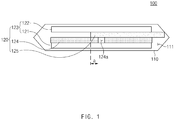
- FIG. 1 is a conceptual cross-sectional view illustrating a state before a pouch is swelled in a secondary battery according to an embodiment of the present invention.
- a secondary battery 100 comprises an electrode assembly 120 in which a positive electrode 121, separators 124 and 125, and a negative electrode 122 are alternately combined with each other and a pouch 110 accommodating the electrode assembly 120. Also, the separators 124 and 125 comprise a first separator 124 and a second separator disposed between the positive electrode 121 and the negative electrode 122.
- the electrode assembly 120 may be a chargeable and dischargeable power generation element and have a structure in which the electrodes 123 and the separators 124 and 125 are combined and alternately laminated with respect to each other.
- the electrodes 123 may comprise a positive electrode 121 and a negative electrode 122.
- the electrode assembly 120 may have a structure in which the positive electrode 121/the separators 124 and 125/the negative electrode 122 are alternately laminated.
- each of the separators 124 and 125 may be disposed between the positive electrode 121 and the negative electrode 122 and disposed outside the positive electrode 121 and outside the negative electrode 122.
- the separator 124 and 125 is made of an insulation material to electrically insulate the positive electrode 121 from the negative electrode 122.
- the separator 124,125 may be made of, for example, a polyolefin-based resin film such as polyethylene or polypropylene having micropores.
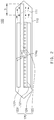
- FIG. 2 is a conceptual cross-sectional view illustrating a state after the pouch is swelled in the secondary battery according to an embodiment of the present invention.
- the separators 124 and 125 may comprise a first separator 124 and a second separator disposed between the positive electrode 121 and the negative electrode 122.
- the first separator 124 may have a through-hole 124a that is penetrated in a direction facing the positive electrode 121 and the negative electrode 122.
- the second separator 125 may cover the through-hole 124a of the first separator 124 and have an end connected to the pouch 110.
- the second separator 125 may have an end fixed to an inner surface of the pouch 110.
- the second separator 125 may move in a lateral direction with respect to the direction in which the positive electrode 121, the separators 124 and 125, and the negative electrode 122 are laminated.
- the first separator 124 may be bonded to be fixed to the positive electrode 121 or the negative electrode 122, which face each other, and the second separator 125 may be slidably provided without being boned to the positive electrode 121 or the negative electrode 122, which face each other.
- One end of the second separator 125 may be fixed to a portion of the pouch 110, which is disposed in the lateral direction with respect to the direction in which the positive electrode 121, the separators 124 and 125, and the negative electrode 122 are laminated.
- a spaced distance a between the other end of the second separator 125 and the through-hole 124a of the first separator 124 may be less than an expansion width b of the pouch when the internal gas is generated.
- the through-hole 124a may be exposed.
- the spaced distance a may be less than an allowable expansion width of the pouch 110.
- safety of the battery may be surely ensured within an allowable range.
- the first separator 124 may be laminated on one surface of the positive electrode 121
- the second separator 125 may be laminated on one surface of the first separator 124
- the negative electrode 122 may be laminated on one surface of the second separator 125.
- the pouch 110 may comprise an accommodation part 111 accommodating the electrode assembly 120 and an electrolyte.
- the pouch 110 may be made of, for example, a flexible material.
- the pouch may be constituted by a plurality of layers.
- an intermediate layer may be provided as an aluminum (Al) layer, and each of both layers may be provided as a resin layer made of a synthetic resin.
- the pouch 110 may be constituted by a plurality of layers in which a polypropylene (PP) layer, a nylon layer, an aluminum (Al) layer, and a polyethylene terephthalate (PET) layer are laminated in order from the inside to the outside of the accommodation part 111.
- PP polypropylene
- nylon nylon
- Al aluminum
- PET polyethylene terephthalate
- the end of the second separator 125 may move in the expansion direction of the pouch 110 to allow the portion of the second separator 125, which covers the through-hole 124a of the first separator 124, to move so as to open the through-hole 124a.
- the through-hole 124a of the first separator 124 may be opened due to the expansion of the pouch 110 to allow the positive electrode 121 and the negative electrode 122, which are disposed on both sides of the first separator 124, to contact with each other through the through-hole 124a of the first separator 124, thereby causing short circuit.
- the power supply may be interrupted by the internal short circuit to interrupt the overcharging. Since the short circuit is designed with the safety range of the pouch 110, the ignition due to the internal short circuit may not occur.
- FIG. 3 is a conceptual cross-sectional view of a secondary battery according to another embodiment of the present invention
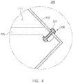
- FIG. 4 is an enlarged cross-sectional view of a portion A of FIG. 3 .
- a secondary battery 200 according to another embodiment of the present invention is different from the secondary battery 100 according to the foregoing embodiment in that a fixing unit 230 for fixing an end of a second separator 125 to a pouch 110 is provided.
- a fixing unit 230 for fixing an end of a second separator 125 to a pouch 110 is provided.
- the secondary battery 200 comprises an electrode assembly 120 in which a positive electrode 121, separators 124 and 125, and a negative electrode 122 are combined and alternately laminated with respect to each other and a pouch 110 accommodating the electrode assembly 120.
- the separators 124 and 125 comprise a first separator 124 and a second separator disposed between the positive electrode 121 and the negative electrode 122.
- the fixing unit 230 for fixing the end of the second separator 125 to the pouch 110 may be further provided.
- the fixing unit 230 may fix the end of the second separator 125 to the pouch 110.
- an insulation layer 231 may be applied to an outer surface of the fixing unit 230 to electrically insulate the pouch 110 from the fixing unit 230 when the end of the second separator 125 is fixed to the pouch 110 through the fixing unit 230.
- the fixing unit 230 may comprise, for example, a rivet.
- the end of the second separator 125 since the end of the second separator 125 is fixed to the pouch 110 through the fixing unit 230, when the pouch 110 is expanded due to overcharging, the end of the second separator 125 may easily move in an expansion direction of the pouch 110 without separating the end of the second separator 125 from the pouch 110. Thus, when the pouch 110 is expanded, the end of the second separator 125 may move in the expansion direction of the pouch 110 to allow a portion of the second separator 125, which covers a through-hole 124a of the first separator 124, to move so as to easily open the through-hole 124a.
- the through-hole 124a of the first separator 124 may be opened due to the expansion of the pouch 110 to allow the positive electrode 121 and the negative electrode 122, which are disposed on both sides of the first separator 124, to contact with each other through the through-hole 124a of the first separator 124, thereby causing short circuit and easily interrupting the overcharging.
Landscapes
- Chemical & Material Sciences (AREA)
- Chemical Kinetics & Catalysis (AREA)
- Electrochemistry (AREA)
- General Chemical & Material Sciences (AREA)
- Engineering & Computer Science (AREA)
- Manufacturing & Machinery (AREA)
- Cell Separators (AREA)
- Secondary Cells (AREA)
Abstract
Description
- The present application claims the benefit of the priority of Korean Patent Application No.
10-2017-0144685, filed on November 01, 2017 - The present invention relate to a secondary battery.
- Rechargeable batteries are rechargeable unlike primarily batteries, and also, the possibility of compact size and high capacity is high. Thus, recently, many studies on rechargeable batteries are being carried out. As technology development and demands for mobile devices increase, the demands for rechargeable batteries as energy sources are rapidly increasing.
- Rechargeable batteries are classified into coin type batteries, cylindrical type batteries, prismatic type batteries, and pouch type batteries according to a shape of a battery case. In such a secondary battery, an electrode assembly mounted in a battery case is a chargeable and dischargeable power generating device having a structure in which an electrode and a separator are stacked.
- Also, the electrode assembly may be approximately classified into a jelly-roll type electrode assembly in which a separator is interposed between a positive electrode and a negative electrode, each of which is provided as the form of a sheet coated with an active material, and then, the positive electrode, the separator, and the negative electrode are wound, a stacked type electrode assembly in which a plurality of positive and negative electrodes with a separator therebetween are sequentially stacked, and a stack/folding type electrode assembly in which stacked type unit cells are wound together with a separation film having a long length.
- The secondary battery may have a risk of ignition and explosion due to overcharge thereof, and thus, it is necessary to prevent the secondary battery from being overcharged.
- One aspect of the present invention is to provide a secondary battery that is capable of interrupting overcharging when the secondary battery is overcharged..
- A secondary battery comprises: an electrode assembly in which a positive electrode, a separator, and a negative electrode are alternately combined to be laminated and a pouch accommodating the electrode assembly therein, wherein the separator comprises: a first separator disposed between the positive electrode and the negative electrode and having a through-hole penetrated in a direction facing the positive electrode and the negative electrode and a second separator covering the through-hole of the first separator and having an end connected to the pouch, wherein, when an internal gas is generated due to overcharging, the pouch is expanded to allow the second separator to move so as to open the through-hole of the first separator so that the positive electrode and the negative electrode contact each other through the through-hole.
- According to the present invention, the separator may be provided in the form in which the positive electrode and the negative electrode are short-circuited with each other when the pouch is swelled by the generation of the gas while the secondary battery is overcharged to interrupt the power supply due to the internal short circuit, thereby interrupting the overcharging.
-
-
FIG. 1 is a conceptual cross-sectional view illustrating a state before a pouch is swelled in a secondary battery according to an embodiment of the present invention. -
FIG. 2 is a conceptual cross-sectional view illustrating a state after the pouch is swelled in the secondary battery according to an embodiment of the present invention. -
FIG. 3 is a conceptual cross-sectional view of a secondary battery according to another embodiment of the present invention. -
FIG. 4 is an enlarged cross-sectional view of a portion A ofFIG. 3 . - The objectives, specific advantages, and novel features of the present invention will become more apparent from the following detailed description taken in conjunction with the accompanying drawings. It should be noted that the reference numerals are added to the components of the drawings in the present specification with the same numerals as possible, even if they are illustrated in other drawings. Also, the present invention may be embodied in different forms and should not be construed as limited to the embodiments set forth herein. In the following description of the present invention, the detailed descriptions of related arts which may unnecessarily obscure the gist of the present invention will be omitted.
-
FIG. 1 is a conceptual cross-sectional view illustrating a state before a pouch is swelled in a secondary battery according to an embodiment of the present invention. - Referring to
FIG. 1 , asecondary battery 100 according to an embodiment of the present invention comprises anelectrode assembly 120 in which apositive electrode 121,separators negative electrode 122 are alternately combined with each other and apouch 110 accommodating theelectrode assembly 120. Also, theseparators first separator 124 and a second separator disposed between thepositive electrode 121 and thenegative electrode 122. - Hereinafter, the secondary battery according to an embodiment of the present invention will be described in more detail with reference to
FIGS. 1 and2 . - Referring to
FIG. 1 , theelectrode assembly 120 may be a chargeable and dischargeable power generation element and have a structure in which theelectrodes 123 and theseparators - The
electrodes 123 may comprise apositive electrode 121 and anegative electrode 122. Here, theelectrode assembly 120 may have a structure in which thepositive electrode 121/theseparators negative electrode 122 are alternately laminated. Here, each of theseparators positive electrode 121 and thenegative electrode 122 and disposed outside thepositive electrode 121 and outside thenegative electrode 122. - The
separator positive electrode 121 from thenegative electrode 122. Here, the separator 124,125 may be made of, for example, a polyolefin-based resin film such as polyethylene or polypropylene having micropores. -
FIG. 2 is a conceptual cross-sectional view illustrating a state after the pouch is swelled in the secondary battery according to an embodiment of the present invention. - Referring to
FIGS. 1 and2 , theseparators first separator 124 and a second separator disposed between thepositive electrode 121 and thenegative electrode 122. - The
first separator 124 may have a through-hole 124a that is penetrated in a direction facing thepositive electrode 121 and thenegative electrode 122. - The
second separator 125 may cover the through-hole 124a of thefirst separator 124 and have an end connected to thepouch 110. - Also, the
second separator 125 may have an end fixed to an inner surface of thepouch 110. Thus, when thepouch 110 is swelled due to generation of an internal gas, thesecond separator 125 may move in a lateral direction with respect to the direction in which thepositive electrode 121, theseparators negative electrode 122 are laminated. - Here, the
first separator 124 may be bonded to be fixed to thepositive electrode 121 or thenegative electrode 122, which face each other, and thesecond separator 125 may be slidably provided without being boned to thepositive electrode 121 or thenegative electrode 122, which face each other. - One end of the
second separator 125 may be fixed to a portion of thepouch 110, which is disposed in the lateral direction with respect to the direction in which thepositive electrode 121, theseparators negative electrode 122 are laminated. - Also, a spaced distance a between the other end of the
second separator 125 and the through-hole 124a of thefirst separator 124, which is measured in a normal state, may be less than an expansion width b of the pouch when the internal gas is generated. Thus, when the pouch is expanded, the through-hole 124a may be exposed. - Particularly, the spaced distance a may be less than an allowable expansion width of the
pouch 110. Thus, safety of the battery may be surely ensured within an allowable range. - The
first separator 124 may be laminated on one surface of thepositive electrode 121, thesecond separator 125 may be laminated on one surface of thefirst separator 124, and thenegative electrode 122 may be laminated on one surface of thesecond separator 125. - The
pouch 110 may comprise anaccommodation part 111 accommodating theelectrode assembly 120 and an electrolyte. - Furthermore, the
pouch 110 may be made of, for example, a flexible material. - For example, the pouch may be constituted by a plurality of layers. Here, an intermediate layer may be provided as an aluminum (Al) layer, and each of both layers may be provided as a resin layer made of a synthetic resin.
- For another example, the
pouch 110 may be constituted by a plurality of layers in which a polypropylene (PP) layer, a nylon layer, an aluminum (Al) layer, and a polyethylene terephthalate (PET) layer are laminated in order from the inside to the outside of theaccommodation part 111. - In the above-described
secondary battery 100 according to an embodiment of the present invention, when thepouch 110 is expanded by the internal gas generated due to the overcharging, the end of thesecond separator 125 may move in the expansion direction of thepouch 110 to allow the portion of thesecond separator 125, which covers the through-hole 124a of thefirst separator 124, to move so as to open the through-hole 124a. Thus, when the overcharging occurs, the through-hole 124a of thefirst separator 124 may be opened due to the expansion of thepouch 110 to allow thepositive electrode 121 and thenegative electrode 122, which are disposed on both sides of thefirst separator 124, to contact with each other through the through-hole 124a of thefirst separator 124, thereby causing short circuit. Thus, the power supply may be interrupted by the internal short circuit to interrupt the overcharging. Since the short circuit is designed with the safety range of thepouch 110, the ignition due to the internal short circuit may not occur. -
FIG. 3 is a conceptual cross-sectional view of a secondary battery according to another embodiment of the present invention, andFIG. 4 is an enlarged cross-sectional view of a portion A ofFIG. 3 . - Referring to
FIGS. 3 and4 , asecondary battery 200 according to another embodiment of the present invention is different from thesecondary battery 100 according to the foregoing embodiment in that afixing unit 230 for fixing an end of asecond separator 125 to apouch 110 is provided. Thus, contents of this embodiment, which are duplicated with those according to the forgoing embodiment, will be briefly described, and also, differences therebetween will be mainly described. - The
secondary battery 200 according to another embodiment of the present invention comprises anelectrode assembly 120 in which apositive electrode 121,separators negative electrode 122 are combined and alternately laminated with respect to each other and apouch 110 accommodating theelectrode assembly 120. Also, theseparators first separator 124 and a second separator disposed between thepositive electrode 121 and thenegative electrode 122. Furthermore, the fixingunit 230 for fixing the end of thesecond separator 125 to thepouch 110 may be further provided. - In more detail, the fixing
unit 230 may fix the end of thesecond separator 125 to thepouch 110. - Here, an
insulation layer 231 may be applied to an outer surface of the fixingunit 230 to electrically insulate thepouch 110 from the fixingunit 230 when the end of thesecond separator 125 is fixed to thepouch 110 through the fixingunit 230. - Here, the fixing
unit 230 may comprise, for example, a rivet. - Thus, in the
secondary battery 200 according to another embodiment of the present invention, since the end of thesecond separator 125 is fixed to thepouch 110 through the fixingunit 230, when thepouch 110 is expanded due to overcharging, the end of thesecond separator 125 may easily move in an expansion direction of thepouch 110 without separating the end of thesecond separator 125 from thepouch 110. Thus, when thepouch 110 is expanded, the end of thesecond separator 125 may move in the expansion direction of thepouch 110 to allow a portion of thesecond separator 125, which covers a through-hole 124a of thefirst separator 124, to move so as to easily open the through-hole 124a. As a result, when the overcharging occurs, the through-hole 124a of thefirst separator 124 may be opened due to the expansion of thepouch 110 to allow thepositive electrode 121 and thenegative electrode 122, which are disposed on both sides of thefirst separator 124, to contact with each other through the through-hole 124a of thefirst separator 124, thereby causing short circuit and easily interrupting the overcharging. - While the present invention has been particularly shown and described with reference to exemplary embodiments thereof, it is to be understood that the scope of the present invention is not limited to the secondary battery according to the present invention. It will be understood by those of ordinary skill in the art that various changes in form and details may be made therein without departing from the spirit and scope of the invention.
- Furthermore, the scope of protection of the present invention will be clarified by the appended claims.
Claims (8)
- A secondary battery comprising:an electrode assembly in which a positive electrode, a separator, and a negative electrode are alternately combined to be laminated; anda pouch accommodating the electrode assembly therein,wherein the separator comprises:a first separator disposed between the positive electrode and the negative electrode and having a through-hole penetrated in a direction facing the positive electrode and the negative electrode; anda second separator covering the through-hole of the first separator and having an end connected to the pouch,wherein, when an internal gas is generated due to overcharging, the pouch is expanded to allow the second separator to move so as to open the through-hole of the first separator so that the positive electrode and the negative electrode contact each other through the through-hole.
- The secondary battery of claim 1, wherein the end of the second separator is fixed to an inner surface of the pouch, and
when the pouch is expanded due to the generation of the internal gas, the second separator moves in a lateral direction with respect to a direction in which the positive electrode, the separator, and the negative electrode are laminated. - The secondary battery of claim 1, wherein the first separator is laminated on one surface of the positive electrode, the second separator is laminated on one surface of the first separator, and the negative electrode is laminated on one surface of the second separator.
- The secondary battery of claim 1, wherein the first separator is bonded to be fixed to the positive electrode or the negative electrode, which face each other, and the second separator is slidably provided without being bonded to the positive electrode or the negative electrode, which face each other.
- The secondary battery of claim 1, wherein one end of the second separator is fixed to a portion of the pouch, which is disposed in a lateral direction with respect to a direction in which the positive electrode, the separator, and the negative electrode are laminated, and
a spaced distance between the other end of the second separator and the through-hole of the first separator, which is measured in a normal state, is less than an allowable expansion width of the pouch. - The secondary battery of claim 1, wherein the end of the second separator is fixed to the pouch through a fixing unit.
- The secondary battery of claim 6, wherein the fixing unit comprises a rivet.
- The secondary battery of claim 6 or 7, wherein an insulation layer is applied to an outer surface of the fixing unit.
Applications Claiming Priority (2)
| Application Number | Priority Date | Filing Date | Title |
|---|---|---|---|
| KR1020170144685A KR102217449B1 (en) | 2017-11-01 | 2017-11-01 | Rechargeable battery |
| PCT/KR2018/010097 WO2019088434A1 (en) | 2017-11-01 | 2018-08-30 | Secondary battery |
Publications (3)
| Publication Number | Publication Date |
|---|---|
| EP3654412A1 true EP3654412A1 (en) | 2020-05-20 |
| EP3654412A4 EP3654412A4 (en) | 2020-08-12 |
| EP3654412B1 EP3654412B1 (en) | 2025-06-18 |
Family
ID=66332044
Family Applications (1)
| Application Number | Title | Priority Date | Filing Date |
|---|---|---|---|
| EP18873745.6A Active EP3654412B1 (en) | 2017-11-01 | 2018-08-30 | Secondary battery |
Country Status (8)
| Country | Link |
|---|---|
| US (1) | US11128015B2 (en) |
| EP (1) | EP3654412B1 (en) |
| KR (1) | KR102217449B1 (en) |
| CN (1) | CN111033812B (en) |
| ES (1) | ES3036149T3 (en) |
| HU (1) | HUE072181T2 (en) |
| PL (1) | PL3654412T3 (en) |
| WO (1) | WO2019088434A1 (en) |
Families Citing this family (4)
| Publication number | Priority date | Publication date | Assignee | Title |
|---|---|---|---|---|
| KR102734360B1 (en) * | 2019-08-07 | 2024-11-27 | 주식회사 엘지에너지솔루션 | Electrochemical Device for Short Circuit Induction and Method of Evaluation for Safety Using Thereof |
| KR102807656B1 (en) * | 2020-05-13 | 2025-05-14 | 주식회사 엘지에너지솔루션 | Rechargeable battery |
| KR20230082260A (en) | 2021-12-01 | 2023-06-08 | 주식회사 엘지에너지솔루션 | Device and method for causing a short circuit inside the battery |
| KR20240139472A (en) * | 2023-03-14 | 2024-09-23 | 주식회사 엘지에너지솔루션 | Secondary battery for testing internal short, preparing method and testing method thereof |
Family Cites Families (15)
| Publication number | Priority date | Publication date | Assignee | Title |
|---|---|---|---|---|
| FR2745959B1 (en) * | 1996-03-08 | 1998-07-10 | Sorapec Lab | IMPROVEMENTS IN OR RELATING TO THE NI-ZN ACCUMULATOR USING ANOLYTE, CATHOLYTE AND MEMBRANE FOR DENDRITE FORMATION |
| JP4984456B2 (en) | 2005-08-19 | 2012-07-25 | トヨタ自動車株式会社 | battery |
| KR101308195B1 (en) | 2006-04-27 | 2013-09-26 | 삼성에스디아이 주식회사 | Electrode assembly and Lithium rechargeable battery comprising the same and Method of making lithium rechargeable battery |
| JP2008041606A (en) | 2006-08-10 | 2008-02-21 | Matsushita Electric Ind Co Ltd | Nonaqueous electrolyte battery separator and nonaqueous electrolyte battery |
| JP2009227923A (en) | 2008-03-25 | 2009-10-08 | Kyoritsu Kagaku Sangyo Kk | Manufacturing method for article having negative pattern |
| US9178204B2 (en) * | 2009-12-07 | 2015-11-03 | Samsung Sdi Co., Ltd. | Rechargeable battery |
| KR101472168B1 (en) * | 2011-07-29 | 2014-12-12 | 주식회사 엘지화학 | Secondary battery having improved safety, and battery pack using the same |
| JP2013243070A (en) * | 2012-05-22 | 2013-12-05 | Sanyo Electric Co Ltd | Battery with wound electrode body |
| KR101528001B1 (en) | 2012-06-22 | 2015-06-10 | 주식회사 엘지화학 | Electrode assembly, manufacture thereof, and secondary batteries including same |
| KR101746790B1 (en) * | 2013-07-31 | 2017-06-13 | 주식회사 엘지화학 | Battery Pack Comprising Curved-shaped Protection Circuit Module |
| JP6169789B2 (en) | 2013-07-31 | 2017-07-26 | エルジー・ケム・リミテッド | Curved electrode laminate and battery pack including the same |
| KR101619604B1 (en) * | 2013-09-26 | 2016-05-10 | 주식회사 엘지화학 | Method of manufacturing electrode assembly and secondary battery |
| US10290839B2 (en) * | 2014-04-25 | 2019-05-14 | Nec Energy Devices, Ltd. | Secondary battery |
| WO2016063838A1 (en) * | 2014-10-21 | 2016-04-28 | 日本電気株式会社 | Secondary battery and production method therefor |
| KR101755861B1 (en) | 2015-10-16 | 2017-07-07 | 현대자동차주식회사 | Battery Cell |
-
2017
- 2017-11-01 KR KR1020170144685A patent/KR102217449B1/en active Active
-
2018
- 2018-08-30 US US16/637,127 patent/US11128015B2/en active Active
- 2018-08-30 HU HUE18873745A patent/HUE072181T2/en unknown
- 2018-08-30 CN CN201880052134.4A patent/CN111033812B/en active Active
- 2018-08-30 ES ES18873745T patent/ES3036149T3/en active Active
- 2018-08-30 WO PCT/KR2018/010097 patent/WO2019088434A1/en not_active Ceased
- 2018-08-30 PL PL18873745.6T patent/PL3654412T3/en unknown
- 2018-08-30 EP EP18873745.6A patent/EP3654412B1/en active Active
Also Published As
| Publication number | Publication date |
|---|---|
| KR20190049146A (en) | 2019-05-09 |
| KR102217449B1 (en) | 2021-02-22 |
| CN111033812A (en) | 2020-04-17 |
| PL3654412T3 (en) | 2025-12-01 |
| CN111033812B (en) | 2022-07-08 |
| ES3036149T3 (en) | 2025-09-15 |
| US11128015B2 (en) | 2021-09-21 |
| EP3654412A4 (en) | 2020-08-12 |
| WO2019088434A1 (en) | 2019-05-09 |
| US20200168875A1 (en) | 2020-05-28 |
| HUE072181T2 (en) | 2025-10-28 |
| EP3654412B1 (en) | 2025-06-18 |
Similar Documents
| Publication | Publication Date | Title |
|---|---|---|
| EP4270565A1 (en) | Electrode assembly and secondary battery comprising same | |
| EP3654412B1 (en) | Secondary battery | |
| KR20140064418A (en) | Secondary battery module | |
| KR102080903B1 (en) | Electrode lead and secondary battery including the same | |
| KR20140041057A (en) | Pouch-type secondary battery | |
| KR102097084B1 (en) | Pouch type secondary battery and battery module including the same | |
| KR101776897B1 (en) | Pouch type secondary battery and method for manufacturing the same | |
| US11362383B2 (en) | Secondary battery | |
| US20220376321A1 (en) | Electrode assembly and secondary battery comprising the same | |
| US10944084B2 (en) | Secondary battery and method for supplementing electrolyte of secondary battery | |
| KR101749729B1 (en) | Secondary battery | |
| EP4224607A1 (en) | Pouch, secondary battery comprising same, and method for manufacturing same | |
| KR20190082180A (en) | Secondary Battery Module | |
| KR102141123B1 (en) | Electrode assembly | |
| KR102298291B1 (en) | Rechargeable battery | |
| KR102158143B1 (en) | Electrode assembly | |
| KR102158146B1 (en) | Rechargeable battery and the manufacturing method | |
| EP3333940B1 (en) | Secondary battery | |
| US20240339737A1 (en) | Pouch-Shaped Battery Cell With Improved Thermal Safety | |
| KR20180041527A (en) | Electrode assembly |
Legal Events
| Date | Code | Title | Description |
|---|---|---|---|
| STAA | Information on the status of an ep patent application or granted ep patent |
Free format text: STATUS: THE INTERNATIONAL PUBLICATION HAS BEEN MADE |
|
| PUAI | Public reference made under article 153(3) epc to a published international application that has entered the european phase |
Free format text: ORIGINAL CODE: 0009012 |
|
| STAA | Information on the status of an ep patent application or granted ep patent |
Free format text: STATUS: REQUEST FOR EXAMINATION WAS MADE |
|
| 17P | Request for examination filed |
Effective date: 20200211 |
|
| AK | Designated contracting states |
Kind code of ref document: A1 Designated state(s): AL AT BE BG CH CY CZ DE DK EE ES FI FR GB GR HR HU IE IS IT LI LT LU LV MC MK MT NL NO PL PT RO RS SE SI SK SM TR |
|
| AX | Request for extension of the european patent |
Extension state: BA ME |
|
| A4 | Supplementary search report drawn up and despatched |
Effective date: 20200714 |
|
| RIC1 | Information provided on ipc code assigned before grant |
Ipc: H01M 2/34 20060101ALI20200708BHEP Ipc: H01M 2/02 20060101AFI20200708BHEP Ipc: H01M 2/16 20060101ALI20200708BHEP Ipc: H01M 10/42 20060101ALI20200708BHEP Ipc: H01M 2/18 20060101ALI20200708BHEP Ipc: H01M 10/0585 20100101ALI20200708BHEP |
|
| DAV | Request for validation of the european patent (deleted) | ||
| DAX | Request for extension of the european patent (deleted) | ||
| RAP1 | Party data changed (applicant data changed or rights of an application transferred) |
Owner name: LG ENERGY SOLUTION LTD. |
|
| RAP3 | Party data changed (applicant data changed or rights of an application transferred) |
Owner name: LG ENERGY SOLUTION, LTD. |
|
| STAA | Information on the status of an ep patent application or granted ep patent |
Free format text: STATUS: EXAMINATION IS IN PROGRESS |
|
| 17Q | First examination report despatched |
Effective date: 20221208 |
|
| REG | Reference to a national code |
Ref country code: DE Ref legal event code: R079 Free format text: PREVIOUS MAIN CLASS: H01M0002340000 Ipc: H01M0010058500 Ref document number: 602018082768 Country of ref document: DE |
|
| GRAP | Despatch of communication of intention to grant a patent |
Free format text: ORIGINAL CODE: EPIDOSNIGR1 |
|
| STAA | Information on the status of an ep patent application or granted ep patent |
Free format text: STATUS: GRANT OF PATENT IS INTENDED |
|
| RIC1 | Information provided on ipc code assigned before grant |
Ipc: H01M 50/129 20210101ALN20250123BHEP Ipc: H01M 50/121 20210101ALN20250123BHEP Ipc: H01M 50/119 20210101ALN20250123BHEP Ipc: H01M 50/578 20210101ALI20250123BHEP Ipc: H01M 10/42 20060101ALI20250123BHEP Ipc: H01M 10/0585 20100101AFI20250123BHEP |
|
| INTG | Intention to grant announced |
Effective date: 20250205 |
|
| P01 | Opt-out of the competence of the unified patent court (upc) registered |
Free format text: CASE NUMBER: APP_13936/2025 Effective date: 20250321 |
|
| GRAS | Grant fee paid |
Free format text: ORIGINAL CODE: EPIDOSNIGR3 |
|
| GRAA | (expected) grant |
Free format text: ORIGINAL CODE: 0009210 |
|
| STAA | Information on the status of an ep patent application or granted ep patent |
Free format text: STATUS: THE PATENT HAS BEEN GRANTED |
|
| AK | Designated contracting states |
Kind code of ref document: B1 Designated state(s): AL AT BE BG CH CY CZ DE DK EE ES FI FR GB GR HR HU IE IS IT LI LT LU LV MC MK MT NL NO PL PT RO RS SE SI SK SM TR |
|
| REG | Reference to a national code |
Ref country code: GB Ref legal event code: FG4D |
|
| REG | Reference to a national code |
Ref country code: CH Ref legal event code: EP |
|
| REG | Reference to a national code |
Ref country code: DE Ref legal event code: R096 Ref document number: 602018082768 Country of ref document: DE |
|
| REG | Reference to a national code |
Ref country code: CH Ref legal event code: EP |
|
| REG | Reference to a national code |
Ref country code: IE Ref legal event code: FG4D |
|
| REG | Reference to a national code |
Ref country code: SE Ref legal event code: TRGR |
|
| REG | Reference to a national code |
Ref country code: ES Ref legal event code: FG2A Ref document number: 3036149 Country of ref document: ES Kind code of ref document: T3 Effective date: 20250915 |
|
| PG25 | Lapsed in a contracting state [announced via postgrant information from national office to epo] |
Ref country code: FI Free format text: LAPSE BECAUSE OF FAILURE TO SUBMIT A TRANSLATION OF THE DESCRIPTION OR TO PAY THE FEE WITHIN THE PRESCRIBED TIME-LIMIT Effective date: 20250618 |
|
| PGFP | Annual fee paid to national office [announced via postgrant information from national office to epo] |
Ref country code: ES Payment date: 20250911 Year of fee payment: 8 |
|
| PGFP | Annual fee paid to national office [announced via postgrant information from national office to epo] |
Ref country code: DE Payment date: 20250721 Year of fee payment: 8 |
|
| REG | Reference to a national code |
Ref country code: LT Ref legal event code: MG9D |
|
| PG25 | Lapsed in a contracting state [announced via postgrant information from national office to epo] |
Ref country code: GR Free format text: LAPSE BECAUSE OF FAILURE TO SUBMIT A TRANSLATION OF THE DESCRIPTION OR TO PAY THE FEE WITHIN THE PRESCRIBED TIME-LIMIT Effective date: 20250919 Ref country code: NO Free format text: LAPSE BECAUSE OF FAILURE TO SUBMIT A TRANSLATION OF THE DESCRIPTION OR TO PAY THE FEE WITHIN THE PRESCRIBED TIME-LIMIT Effective date: 20250918 |
|
| PG25 | Lapsed in a contracting state [announced via postgrant information from national office to epo] |
Ref country code: BG Free format text: LAPSE BECAUSE OF FAILURE TO SUBMIT A TRANSLATION OF THE DESCRIPTION OR TO PAY THE FEE WITHIN THE PRESCRIBED TIME-LIMIT Effective date: 20250618 |
|
| PGFP | Annual fee paid to national office [announced via postgrant information from national office to epo] |
Ref country code: HU Payment date: 20250929 Year of fee payment: 8 Ref country code: BE Payment date: 20250722 Year of fee payment: 8 Ref country code: GB Payment date: 20250722 Year of fee payment: 8 |
|
| PG25 | Lapsed in a contracting state [announced via postgrant information from national office to epo] |
Ref country code: HR Free format text: LAPSE BECAUSE OF FAILURE TO SUBMIT A TRANSLATION OF THE DESCRIPTION OR TO PAY THE FEE WITHIN THE PRESCRIBED TIME-LIMIT Effective date: 20250618 |
|
| PGFP | Annual fee paid to national office [announced via postgrant information from national office to epo] |
Ref country code: FR Payment date: 20250725 Year of fee payment: 8 |
|
| PGFP | Annual fee paid to national office [announced via postgrant information from national office to epo] |
Ref country code: SE Payment date: 20250722 Year of fee payment: 8 |
|
| PG25 | Lapsed in a contracting state [announced via postgrant information from national office to epo] |
Ref country code: RS Free format text: LAPSE BECAUSE OF FAILURE TO SUBMIT A TRANSLATION OF THE DESCRIPTION OR TO PAY THE FEE WITHIN THE PRESCRIBED TIME-LIMIT Effective date: 20250918 |
|
| REG | Reference to a national code |
Ref country code: NL Ref legal event code: MP Effective date: 20250618 |
|
| REG | Reference to a national code |
Ref country code: HU Ref legal event code: AG4A Ref document number: E072181 Country of ref document: HU |
|
| PG25 | Lapsed in a contracting state [announced via postgrant information from national office to epo] |
Ref country code: LV Free format text: LAPSE BECAUSE OF FAILURE TO SUBMIT A TRANSLATION OF THE DESCRIPTION OR TO PAY THE FEE WITHIN THE PRESCRIBED TIME-LIMIT Effective date: 20250618 |
|
| PG25 | Lapsed in a contracting state [announced via postgrant information from national office to epo] |
Ref country code: NL Free format text: LAPSE BECAUSE OF FAILURE TO SUBMIT A TRANSLATION OF THE DESCRIPTION OR TO PAY THE FEE WITHIN THE PRESCRIBED TIME-LIMIT Effective date: 20250618 |
|
| PG25 | Lapsed in a contracting state [announced via postgrant information from national office to epo] |
Ref country code: PT Free format text: LAPSE BECAUSE OF FAILURE TO SUBMIT A TRANSLATION OF THE DESCRIPTION OR TO PAY THE FEE WITHIN THE PRESCRIBED TIME-LIMIT Effective date: 20251020 |
|
| REG | Reference to a national code |
Ref country code: AT Ref legal event code: MK05 Ref document number: 1805074 Country of ref document: AT Kind code of ref document: T Effective date: 20250618 |
|
| PG25 | Lapsed in a contracting state [announced via postgrant information from national office to epo] |
Ref country code: IS Free format text: LAPSE BECAUSE OF FAILURE TO SUBMIT A TRANSLATION OF THE DESCRIPTION OR TO PAY THE FEE WITHIN THE PRESCRIBED TIME-LIMIT Effective date: 20251018 |
|
| PG25 | Lapsed in a contracting state [announced via postgrant information from national office to epo] |
Ref country code: AT Free format text: LAPSE BECAUSE OF FAILURE TO SUBMIT A TRANSLATION OF THE DESCRIPTION OR TO PAY THE FEE WITHIN THE PRESCRIBED TIME-LIMIT Effective date: 20250618 Ref country code: SM Free format text: LAPSE BECAUSE OF FAILURE TO SUBMIT A TRANSLATION OF THE DESCRIPTION OR TO PAY THE FEE WITHIN THE PRESCRIBED TIME-LIMIT Effective date: 20250618 |
|
| PG25 | Lapsed in a contracting state [announced via postgrant information from national office to epo] |
Ref country code: CZ Free format text: LAPSE BECAUSE OF FAILURE TO SUBMIT A TRANSLATION OF THE DESCRIPTION OR TO PAY THE FEE WITHIN THE PRESCRIBED TIME-LIMIT Effective date: 20250618 |
|
| PGFP | Annual fee paid to national office [announced via postgrant information from national office to epo] |
Ref country code: PL Payment date: 20250728 Year of fee payment: 8 |
|
| PG25 | Lapsed in a contracting state [announced via postgrant information from national office to epo] |
Ref country code: EE Free format text: LAPSE BECAUSE OF FAILURE TO SUBMIT A TRANSLATION OF THE DESCRIPTION OR TO PAY THE FEE WITHIN THE PRESCRIBED TIME-LIMIT Effective date: 20250618 |
|
| PG25 | Lapsed in a contracting state [announced via postgrant information from national office to epo] |
Ref country code: SK Free format text: LAPSE BECAUSE OF FAILURE TO SUBMIT A TRANSLATION OF THE DESCRIPTION OR TO PAY THE FEE WITHIN THE PRESCRIBED TIME-LIMIT Effective date: 20250618 Ref country code: RO Free format text: LAPSE BECAUSE OF FAILURE TO SUBMIT A TRANSLATION OF THE DESCRIPTION OR TO PAY THE FEE WITHIN THE PRESCRIBED TIME-LIMIT Effective date: 20250618 |
|
| REG | Reference to a national code |
Ref country code: DE Ref legal event code: R097 Ref document number: 602018082768 Country of ref document: DE |
|
| REG | Reference to a national code |
Ref country code: CH Ref legal event code: H13 Free format text: ST27 STATUS EVENT CODE: U-0-0-H10-H13 (AS PROVIDED BY THE NATIONAL OFFICE) Effective date: 20260324 |
|
| PG25 | Lapsed in a contracting state [announced via postgrant information from national office to epo] |
Ref country code: MC Free format text: LAPSE BECAUSE OF FAILURE TO SUBMIT A TRANSLATION OF THE DESCRIPTION OR TO PAY THE FEE WITHIN THE PRESCRIBED TIME-LIMIT Effective date: 20250618 |
|
| PG25 | Lapsed in a contracting state [announced via postgrant information from national office to epo] |
Ref country code: DK Free format text: LAPSE BECAUSE OF FAILURE TO SUBMIT A TRANSLATION OF THE DESCRIPTION OR TO PAY THE FEE WITHIN THE PRESCRIBED TIME-LIMIT Effective date: 20250618 |
|
| PG25 | Lapsed in a contracting state [announced via postgrant information from national office to epo] |
Ref country code: LU Free format text: LAPSE BECAUSE OF NON-PAYMENT OF DUE FEES Effective date: 20250830 Ref country code: IT Free format text: LAPSE BECAUSE OF FAILURE TO SUBMIT A TRANSLATION OF THE DESCRIPTION OR TO PAY THE FEE WITHIN THE PRESCRIBED TIME-LIMIT Effective date: 20250618 |
|
| PG25 | Lapsed in a contracting state [announced via postgrant information from national office to epo] |
Ref country code: CH Free format text: LAPSE BECAUSE OF NON-PAYMENT OF DUE FEES Effective date: 20250831 |
|
| PLBE | No opposition filed within time limit |
Free format text: ORIGINAL CODE: 0009261 |
|
| STAA | Information on the status of an ep patent application or granted ep patent |
Free format text: STATUS: NO OPPOSITION FILED WITHIN TIME LIMIT |
|
| REG | Reference to a national code |
Ref country code: CH Ref legal event code: L10 Free format text: ST27 STATUS EVENT CODE: U-0-0-L10-L00 (AS PROVIDED BY THE NATIONAL OFFICE) Effective date: 20260430 |