EP3654084A1 - Verfahren zur verwendung von rgb-überlagerung zur verhinderung der chromatischen dispersion einer vr-vorrichtung und elektronische vorrichtung - Google Patents
Verfahren zur verwendung von rgb-überlagerung zur verhinderung der chromatischen dispersion einer vr-vorrichtung und elektronische vorrichtung Download PDFInfo
- Publication number
- EP3654084A1 EP3654084A1 EP18832653.2A EP18832653A EP3654084A1 EP 3654084 A1 EP3654084 A1 EP 3654084A1 EP 18832653 A EP18832653 A EP 18832653A EP 3654084 A1 EP3654084 A1 EP 3654084A1
- Authority
- EP
- European Patent Office
- Prior art keywords
- point
- displayed
- color
- rgb
- blend
- Prior art date
- Legal status (The legal status is an assumption and is not a legal conclusion. Google has not performed a legal analysis and makes no representation as to the accuracy of the status listed.)
- Pending
Links
Images


Classifications
-
- G—PHYSICS
- G02—OPTICS
- G02B—OPTICAL ELEMENTS, SYSTEMS OR APPARATUS
- G02B27/00—Optical systems or apparatus not provided for by any of the groups G02B1/00 - G02B26/00, G02B30/00
- G02B27/01—Head-up displays
- G02B27/017—Head mounted
-
- G—PHYSICS
- G02—OPTICS
- G02B—OPTICAL ELEMENTS, SYSTEMS OR APPARATUS
- G02B27/00—Optical systems or apparatus not provided for by any of the groups G02B1/00 - G02B26/00, G02B30/00
- G02B27/01—Head-up displays
- G02B27/0101—Head-up displays characterised by optical features
-
- G—PHYSICS
- G09—EDUCATION; CRYPTOGRAPHY; DISPLAY; ADVERTISING; SEALS
- G09G—ARRANGEMENTS OR CIRCUITS FOR CONTROL OF INDICATING DEVICES USING STATIC MEANS TO PRESENT VARIABLE INFORMATION
- G09G5/00—Control arrangements or circuits for visual indicators common to cathode-ray tube indicators and other visual indicators
- G09G5/02—Control arrangements or circuits for visual indicators common to cathode-ray tube indicators and other visual indicators characterised by the way in which colour is displayed
- G09G5/026—Control of mixing and/or overlay of colours in general
-
- G—PHYSICS
- G02—OPTICS
- G02B—OPTICAL ELEMENTS, SYSTEMS OR APPARATUS
- G02B27/00—Optical systems or apparatus not provided for by any of the groups G02B1/00 - G02B26/00, G02B30/00
- G02B27/0025—Optical systems or apparatus not provided for by any of the groups G02B1/00 - G02B26/00, G02B30/00 for optical correction, e.g. distorsion, aberration
-
- G—PHYSICS
- G06—COMPUTING OR CALCULATING; COUNTING
- G06F—ELECTRIC DIGITAL DATA PROCESSING
- G06F3/00—Input arrangements for transferring data to be processed into a form capable of being handled by the computer; Output arrangements for transferring data from processing unit to output unit, e.g. interface arrangements
- G06F3/14—Digital output to display device ; Cooperation and interconnection of the display device with other functional units
- G06F3/147—Digital output to display device ; Cooperation and interconnection of the display device with other functional units using display panels
-
- G—PHYSICS
- G06—COMPUTING OR CALCULATING; COUNTING
- G06T—IMAGE DATA PROCESSING OR GENERATION, IN GENERAL
- G06T5/00—Image enhancement or restoration
- G06T5/80—Geometric correction
-
- G—PHYSICS
- G02—OPTICS
- G02B—OPTICAL ELEMENTS, SYSTEMS OR APPARATUS
- G02B27/00—Optical systems or apparatus not provided for by any of the groups G02B1/00 - G02B26/00, G02B30/00
- G02B27/01—Head-up displays
- G02B27/0101—Head-up displays characterised by optical features
- G02B2027/011—Head-up displays characterised by optical features comprising device for correcting geometrical aberrations, distortion
-
- G—PHYSICS
- G02—OPTICS
- G02B—OPTICAL ELEMENTS, SYSTEMS OR APPARATUS
- G02B27/00—Optical systems or apparatus not provided for by any of the groups G02B1/00 - G02B26/00, G02B30/00
- G02B27/01—Head-up displays
- G02B27/0101—Head-up displays characterised by optical features
- G02B2027/0112—Head-up displays characterised by optical features comprising device for genereting colour display
- G02B2027/0116—Head-up displays characterised by optical features comprising device for genereting colour display comprising devices for correcting chromatic aberration
-
- G—PHYSICS
- G09—EDUCATION; CRYPTOGRAPHY; DISPLAY; ADVERTISING; SEALS
- G09G—ARRANGEMENTS OR CIRCUITS FOR CONTROL OF INDICATING DEVICES USING STATIC MEANS TO PRESENT VARIABLE INFORMATION
- G09G2320/00—Control of display operating conditions
- G09G2320/02—Improving the quality of display appearance
- G09G2320/0242—Compensation of deficiencies in the appearance of colours
-
- G—PHYSICS
- G09—EDUCATION; CRYPTOGRAPHY; DISPLAY; ADVERTISING; SEALS
- G09G—ARRANGEMENTS OR CIRCUITS FOR CONTROL OF INDICATING DEVICES USING STATIC MEANS TO PRESENT VARIABLE INFORMATION
- G09G2340/00—Aspects of display data processing
- G09G2340/10—Mixing of images, i.e. displayed pixel being the result of an operation, e.g. adding, on the corresponding input pixels
-
- G—PHYSICS
- G09—EDUCATION; CRYPTOGRAPHY; DISPLAY; ADVERTISING; SEALS
- G09G—ARRANGEMENTS OR CIRCUITS FOR CONTROL OF INDICATING DEVICES USING STATIC MEANS TO PRESENT VARIABLE INFORMATION
- G09G2340/00—Aspects of display data processing
- G09G2340/12—Overlay of images, i.e. displayed pixel being the result of switching between the corresponding input pixels
Definitions
- the present disclosure relates to a mobile terminal technology field, and more particularly to a method for using RGB blend to prevent chromatic dispersion of a VR device and an electronic device.
- a convex lens is used as a lens of a virtual reality (VR) device. It can be appreciated from a sectional view of the lens that the lens is similar to a prism having a thick thickness at a center and a thin thickness at an edge. Angles of the prism are larger along with the approach to the edge. Accordingly, chromatic dispersion phenomenon is more serious along with the approach to the edge.
- VR virtual reality
- the present disclosure provides a method for using RGB blend to prevent chromatic dispersion of a VR device and an electronic device capable of solving the problem that the colors of a seen image in a conventional smart terminal of the VR device are totally changed and more serious along with the approach to the edge.
- an embodiment of the present disclosure provides a method for using RGB blend to prevent chromatic dispersion of a VR device, wherein the method includes steps of:
- the refractive parameter at the any one point of the lens is acquired according to a curvature of the lens and the refractive index of the lens by calculation or optical simulation.
- the step of acquiring all of the blend points corresponding to the point to be displayed according to the RGB parameter value corresponding to the point to be displayed in the image and the refractive parameter includes:
- the step of acquiring the respective proportions of the red light, the green light, and the blue light corresponding to the point to be displayed includes:
- the steps of blending all of the blend points corresponding to the point to be displayed together and displaying the point to be displayed include:
- a range of R 0 of the RGB parameter value r o (R 0 , G 0 , B 0 ) corresponding to the point to be displayed is [0, 255].
- a range of G 0 of the RGB parameter value r o (R 0 , G 0 , B 0 ) corresponding to the point to be displayed is [0, 255].
- a range of B 0 of the RGB parameter value r o (R 0 , G 0 , B 0 ) corresponding to the point to be displayed is [0, 255].
- An electronic device includes:
- An electronic device includes:
- the refractive parameter at the any one point of the lens is acquired according to the curvature of the lens and the refractive index of the lens by calculation or optical simulation.
- the one or more processors are further configured to perform steps of: acquiring the RGB parameter value r o (R 0 , G 0 , B 0 ) of the point to be displayed in the image, wherein R 0 represents luminance of red light corresponding to the point to be displayed, G 0 represents luminance of green light corresponding to the point to be displayed, and B 0 represents luminance of blue light corresponding to the point to be displayed; acquiring all of the blend points which are blended with the point to be displayed according to a surface shape and the refractive index of the lens, wherein the blend points are respectively denoted as r 1 , r 2 , ...., r m , g 1 , g 2 , ...., g n , r m , b 1 , b 2 , ...., b o ;
- R i represents illuminance of red light corresponding to the color coordinate r i
- a range of i is [1, m]
- G j represents illuminance of green light corresponding to the color coordinate g j
- a range of j is [1, n]
- B k represents illuminance of blue light corresponding to the color coordinate b k
- a range of k is [1, o].
- a range of R 0 of the RGB parameter value r o (R 0 , G 0 , B 0 ) corresponding to the point to be displayed is [0, 255].
- a range of G 0 of the RGB parameter value r o (R 0 , G 0 , B 0 ) corresponding to the point to be displayed is [0, 255].
- a range of B 0 of the RGB parameter value r o (R 0 , G 0 , B 0 ) corresponding to the point to be displayed is [0, 255].
- the refractive parameters at different positions are acquired according to the refractive index and the curvature of the curved surface of the lens.
- the red color, the green color, and the blue color in the image can be displayed directly.
- Blended colors among the red color, the green color, and the blue color are optimized according to refractive situations, and then the refractive parameters at the different positions are acquired.
- the blended colors are acquired according to the refractive parameters, and the respective proportions of the red color, the green color, and the blue color are identified to synthesize the needed colors, thereby avoiding that the chromatic dispersion phenomenon occurs when the blended colors are directly displayed.
- the present disclosure provides a method for using RGB blend to prevent chromatic dispersion of a VR device and an electronic device.
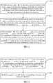
- FIG. 1 illustrates a flow chart of a method for using RGB blend to prevent chromatic dispersion of a VR device in accordance with a preferred embodiment of the present disclosure. As shown in FIG. 1 , the method includes the following steps.
- step S100 a refractive parameter at any one point of a lens is acquired according to a surface shape and a refractive index of the lens.
- step S200 all blend points corresponding to a point to be displayed are acquired according to an RGB parameter value corresponding to the point to be displayed in an image and the refractive parameter.
- step S300 all of the blend points corresponding to the point to be displayed are blended together, and the point to be displayed is displayed.
- a display screen of a mobile phone (or any other device) for a VR device usually uses the three-primary colors including a red color, a green color, and a blue color (RGB) to display an image. Accordingly, chromatic dispersion phenomenon can be improved significantly when an interface for displaying the image (on the display screen of the mobile phone or the display screen of any other device) is designed according to the three-primary colors.
- the three colors are pure colors, and thus the chromatic dispersion phenomenon does not occur.
- the red color, the green color, and the blue color of the display screen of the mobile phone are not shown by single-wavelength light. As such, strictly speaking, the chromatic dispersion phenomenon still exists.
- each point on the display screen can be represented by a color coordinate, for example, (R, G, B).
- R, G, and B respectively represent the red color, the green color, and the blue color.
- Each of the three colors includes 8 bits for representing changes of 256 gray levels. (R, 0, 0), (0, G, 0), and (0, 0, B) respectively represent different gray levels of the red color, the green color, and the blue color.
- the display effect of the image is decreased and the color is not rich although the chromatic dispersion phenomenon can be avoided. Accordingly, it is necessary to compensate the image using any other method. Needed colors can be synthesized by blending the three pure colors. This is because curve degrees of light having different wavelengths are different due to the effect of the lens. As such, a new color seen by human eyes can be synthesized by light positioned at two different points on the screen of the mobile phone and having different wavelengths.
- the green light G (0, 255, 0) and the blue light B (0, 0, 255) at two adjacent points are generated by the display screen of the mobile phone. Since a wavelength of the blue light B is shorter, a curve degree of the blue light B is greater than a curve degree of the green light G due to the effect of the lens. After the green light G and the blue light B pass through the lens, the green light G and the blue light B are blended together. After the green light G and the blue light B are blended together, light which is seen by human eyes is GB (0, 255, 255 ) instead of the green light G and the blue light B.
- refractive parameters at different positions are acquired according to the refractive index and a curvature of a curved surface of the lens.
- the red color, the green color, and the blue color in the image can be displayed directly.
- Blended colors among the red color, the green color, and the blue color are optimized according to refractive situations, and then the refractive parameters at the different positions are acquired.
- the blended colors are acquired according to the refractive parameters, and respective proportions of the red color, the green color, and the blue color are identified to synthesize the needed colors, thereby avoiding that the chromatic dispersion phenomenon occurs when the blended colors are directly displayed.
- the refractive parameter at any one point of the lens is acquired by calculation or optical simulation according to the curvature and the refractive index of the lens.
- the curvatures of limited points on the lens can be acquired by optical simulation.
- Curvatures of other points can be acquired by an interpolation method.
- the refractive parameter of light at each point can be acquired to identify blended weights corresponding to light of the three colors.
- step S200 specifically includes the following steps.
- step S210 it is determined whether the point to be displayed corresponds to one of the red color, the green color, and the blue color according to the RGB parameter value corresponding to the point to be displayed in the image and the refractive parameter. If the point to be displayed corresponds to the one of the red color, the green color, and the blue color, step S300 is performed. If the point to be displayed does not correspond to the one of the red color, the green color, and the blue color, step S220 is performed.
- step S220 the respective proportions of the red color, the green color, and the blue color of the point to be displayed are acquired.
- the blended colors among the red color, the green color, and the blue color are necessary to be optimized according to the refractive situations of the lens. That is, the refractive parameter at the position of the point to be displayed is acquired. The blended color is acquired according to the refractive parameter, and the respective proportions of the red color, the green color, and the blue color are identified to synthesize the needed color. Unnecessary colors can be avoided when different colors are blended together.
- step S220 specifically includes the following steps.
- step S221 the RGB parameter value r o (R 0 , G 0 , B 0 ) of the point to be displayed in the image is acquired.
- R 0 represents luminance of red light corresponding to the point to be displayed.
- G 0 represents luminance of green light corresponding to the point to be displayed.
- B 0 represents luminance of blue light corresponding to the point to be displayed.
- step S222 all of the points which are blended with the point to be displayed are acquired according to the surface shape and the refractive index of the lens.
- the blend points which are blended with the point to be displayed are respectively denoted as r 1 , r 2 , whil, r m , g 1 , g 2 , whil, g n , r m , b 1 , b 2 , ising, b o .
- step S223 color coordinates r 1 (R 1 , 0, 0), r 2 (R 2 , 0, 0), whil, r m (R m , 0, 0), g 1 (0, G 1 , 0), g 2 (0, G 2 ,0), whil, g n (0, G n , 0), b 1 (0, 0, B 1 ), b 2 (0, 0, B 2 ), whil, b o (0, 0, B o ) corresponding to the blend points are acquired.
- R i represents illuminance of red light corresponding to the color coordinate r i .
- a range of i is [1, m].
- G j represents illuminance of green light corresponding to the color coordinate g j .
- a range of j is [1, n].
- B k represents illuminance of blue light corresponding to the color coordinate b k .
- a range of k is [1, o].
- n, o are positive integers
- i, j, and k are also positive integers.
- step S300 specifically includes the following steps.
- step S320 the RGB parameter value r o (R 0 , G 0 , B 0 ) corresponding to the point to be displayed is displayed.
- a range of R 0 of the RGB parameter value r o (R 0 , G 0 , B 0 ) corresponding to the point to be displayed is [0, 255].
- a range of G 0 is [0, 255].
- a range of B 0 is [0, 255].
- the lens Since the lens is symmetrical with respect to the center of the lens, refractive results at points having the same radius are the same. For a point r o on the lens, one point which can be blended with the point r o must be near the point r o and in a radial direction the same as a radial direction of the point r o .
- the RGB parameter r o (R 0 , G 0 , B 0 ) can be acquired by blending r 1 (R 1 , 0, 0), r 2 (R 2 , 0, 0), whil, r m (R m , 0, 0), g 1 (0, G 1 , 0), g 2 (0, G 2 ,0), whil, g n (0, G n , 0), b 1 (0, 0, B 1 ), b 2 (0, 0, B 2 ), ...., b o (0, 0, B o ).
- the display effect of the RGB parameter r o (R 0 , G 0 , B 0 ) can be acquired by blending R 1 , R 2 , ising, R m , G 1 , G 2 , ising, G n , B 1 , B 2 , ising, B o . Accordingly, the method for using the RGB blend to prevent the chromatic dispersion of the VR device of the present disclosure can avoid the chromatic dispersion phenomenon when the blended colors are directly displayed.
- the present disclosure further provides a storage medium storing a plurality of instructions.
- the instructions can be loaded by a processor to perform the steps of the method for using the RGB blend to prevent the chromatic dispersion of the VR device.
- the present disclosure further provides an electronic device including:
- the present disclosure further provides an electronic device including:
- the refractive parameter at the any one point of the lens is acquired according to the curvature of the lens and the refractive index of the lens by calculation or optical simulation.
- the one or more processors are further configured to perform steps of:
- the one or more processors are further configured to perform steps of:
- a range of R 0 of the RGB parameter value r o (R 0 , G 0 , B 0 ) corresponding to the point to be displayed is [0, 255].
- a range of G 0 of the RGB parameter value r o (R 0 , G 0 , B 0 ) corresponding to the point to be displayed is [0, 255].
- a range of B 0 of the RGB parameter value r o (R 0 , G 0 , B 0 ) corresponding to the point to be displayed is [0, 255].
- the refractive parameters at different positions are acquired according to the refractive index and the curvature of the curved surface of the lens.
- the red color, the green color, and the blue color in the image can be displayed directly.
- Blended colors among the red color, the green color, and the blue color are optimized according to refractive situations, and then the refractive parameters at the different positions are acquired.
- the blended colors are acquired according to the refractive parameters, and the respective proportions of the red color, the green color, and the blue color are identified to synthesize the needed colors, thereby avoiding that the chromatic dispersion phenomenon occurs when the blended colors are directly displayed.
Landscapes
- Physics & Mathematics (AREA)
- Engineering & Computer Science (AREA)
- General Physics & Mathematics (AREA)
- Theoretical Computer Science (AREA)
- Optics & Photonics (AREA)
- Computer Hardware Design (AREA)
- Human Computer Interaction (AREA)
- General Engineering & Computer Science (AREA)
- Controls And Circuits For Display Device (AREA)
- Geometry (AREA)
- Processing Or Creating Images (AREA)
- Liquid Crystal (AREA)
Applications Claiming Priority (2)
| Application Number | Priority Date | Filing Date | Title |
|---|---|---|---|
| CN201710572828.8A CN107219629B (zh) | 2017-07-14 | 2017-07-14 | 采用rgb叠加防vr设备色散的方法、存储介质及设备 |
| PCT/CN2018/095624 WO2019011327A1 (zh) | 2017-07-14 | 2018-07-13 | 采用rgb叠加防vr设备色散的方法及电子设备 |
Publications (2)
| Publication Number | Publication Date |
|---|---|
| EP3654084A1 true EP3654084A1 (de) | 2020-05-20 |
| EP3654084A4 EP3654084A4 (de) | 2021-04-28 |
Family
ID=59952293
Family Applications (1)
| Application Number | Title | Priority Date | Filing Date |
|---|---|---|---|
| EP18832653.2A Pending EP3654084A4 (de) | 2017-07-14 | 2018-07-13 | Verfahren zur verwendung von rgb-überlagerung zur verhinderung der chromatischen dispersion einer vr-vorrichtung und elektronische vorrichtung |
Country Status (4)
| Country | Link |
|---|---|
| US (1) | US10991337B2 (de) |
| EP (1) | EP3654084A4 (de) |
| CN (1) | CN107219629B (de) |
| WO (1) | WO2019011327A1 (de) |
Families Citing this family (2)
| Publication number | Priority date | Publication date | Assignee | Title |
|---|---|---|---|---|
| CN107219629B (zh) * | 2017-07-14 | 2021-01-08 | 惠州Tcl移动通信有限公司 | 采用rgb叠加防vr设备色散的方法、存储介质及设备 |
| CN117935726B (zh) * | 2024-03-22 | 2024-05-17 | 深圳市元亨光电股份有限公司 | Mini-LED显示屏色彩均化方法及装置 |
Family Cites Families (18)
| Publication number | Priority date | Publication date | Assignee | Title |
|---|---|---|---|---|
| US6792329B2 (en) * | 2001-08-22 | 2004-09-14 | Milliken & Company | Construction of colored images on absorbent substrates using a computer-aided design system |
| US8339462B2 (en) * | 2008-01-28 | 2012-12-25 | DigitalOptics Corporation Europe Limited | Methods and apparatuses for addressing chromatic abberations and purple fringing |
| US7773849B2 (en) * | 2004-12-14 | 2010-08-10 | Oms Displays Ltd. | Device and method for optical resizing and backlighting |
| EP3868855A1 (de) | 2006-07-13 | 2021-08-25 | DSM IP Assets B.V. | Verbessertes brauverfahren |
| JP5094430B2 (ja) * | 2008-01-10 | 2012-12-12 | キヤノン株式会社 | 画像処理方法、画像処理装置、システム |
| JP5388534B2 (ja) * | 2008-10-09 | 2014-01-15 | キヤノン株式会社 | 画像処理装置およびその方法、頭部装着型ディスプレイ、プログラム、記録媒体 |
| JP5241698B2 (ja) * | 2009-12-25 | 2013-07-17 | キヤノン株式会社 | 画像処理装置および画像処理方法 |
| US8553978B2 (en) * | 2010-11-03 | 2013-10-08 | Csr Technology Inc. | System and method for providing multi resolution purple fringing detection and correction |
| JP2013219705A (ja) * | 2012-04-12 | 2013-10-24 | Sony Corp | 画像処理装置、および画像処理方法、並びにプログラム |
| JP5929567B2 (ja) * | 2012-07-03 | 2016-06-08 | ソニー株式会社 | 画像信号処理装置、および画像信号処理方法、並びにプログラム |
| KR102651578B1 (ko) * | 2013-11-27 | 2024-03-25 | 매직 립, 인코포레이티드 | 가상 및 증강 현실 시스템들 및 방법들 |
| JP6011561B2 (ja) * | 2014-02-27 | 2016-10-19 | ブラザー工業株式会社 | 制御装置、ヘッドマウントディスプレイ、及びプログラム |
| CN104020565B (zh) * | 2014-06-19 | 2016-03-23 | 青岛歌尔声学科技有限公司 | 具有光学透镜和显示屏的显示系统及其图像显示方法 |
| CN104090354B (zh) * | 2014-06-28 | 2016-09-07 | 青岛歌尔声学科技有限公司 | 一种无色差的头戴设备用广角内调焦镜头及头戴设备 |
| CN105807481B (zh) * | 2016-05-25 | 2022-07-15 | 京东方科技集团股份有限公司 | 一种虚拟曲面显示面板、其制作方法及显示装置 |
| CN106791754B (zh) * | 2016-12-22 | 2018-08-21 | 歌尔科技有限公司 | 一种设备色差矫正方法及系统 |
| CN107193124A (zh) * | 2017-05-22 | 2017-09-22 | 吉林大学 | 集成成像高密度小间距led显示参数设计方法 |
| CN107219629B (zh) | 2017-07-14 | 2021-01-08 | 惠州Tcl移动通信有限公司 | 采用rgb叠加防vr设备色散的方法、存储介质及设备 |
-
2017
- 2017-07-14 CN CN201710572828.8A patent/CN107219629B/zh active Active
-
2018
- 2018-07-13 WO PCT/CN2018/095624 patent/WO2019011327A1/zh not_active Ceased
- 2018-07-13 EP EP18832653.2A patent/EP3654084A4/de active Pending
- 2018-07-13 US US16/630,869 patent/US10991337B2/en active Active
Also Published As
| Publication number | Publication date |
|---|---|
| EP3654084A4 (de) | 2021-04-28 |
| US20200152153A1 (en) | 2020-05-14 |
| US10991337B2 (en) | 2021-04-27 |
| CN107219629A (zh) | 2017-09-29 |
| WO2019011327A1 (zh) | 2019-01-17 |
| CN107219629B (zh) | 2021-01-08 |
Similar Documents
| Publication | Publication Date | Title |
|---|---|---|
| EP4207075B1 (de) | Bildverarbeitungsverfahren und -vorrichtung sowie computervorrichtung und speichermedium | |
| US20100090929A1 (en) | Image processing system, image processing apparatus, aberration correction method, and computer-readable storage medium | |
| US20200034947A1 (en) | Method and device for transmitting image data, storage medium, and processor | |
| CA3011808A1 (en) | Method and apparatus for reducing myopiagenic effect of electronic displays | |
| EP2573670B1 (de) | Zeichenanzeigeverfahren und -vorrichtung | |
| US7945092B2 (en) | Pixel processor | |
| WO2016008341A1 (en) | Content sharing methods and apparatuses | |
| EP3654084A1 (de) | Verfahren zur verwendung von rgb-überlagerung zur verhinderung der chromatischen dispersion einer vr-vorrichtung und elektronische vorrichtung | |
| US8373718B2 (en) | Method and system for color enhancement with color volume adjustment and variable shift along luminance axis | |
| CN112133260B (zh) | 图像调节方法及装置 | |
| CN102197411B (zh) | 用于灰度校准的目标显示 | |
| JP2010054729A (ja) | 液晶表示装置および色処理方法 | |
| KR20180036820A (ko) | 영상 처리 장치, 표시 장치 및 두부 장착 표시 장치 | |
| CN110767150A (zh) | 一种解决led屏幕斜视偏色问题的方法 | |
| WO2016008342A1 (en) | Content sharing methods and apparatuses | |
| US11854172B2 (en) | Color contrast enhanced rendering method, device and system suitable for optical see-through head-mounted display | |
| US20190043433A1 (en) | Display method and display device | |
| CN115087390A (zh) | 通过图像颜色校正的色盲补救的方法 | |
| WO2025118999A1 (zh) | 显示差异校正方法及装置、显示装置、设备及介质 | |
| US12586149B2 (en) | Mixed reality recording of foveated display content systems and methods | |
| Oio et al. | Perceptually enhanced shadows for ost ar | |
| US20180247579A1 (en) | Information Processing System, Information Processing Apparatus, Output Apparatus, Program, and Recording Medium | |
| US20240404028A1 (en) | Chromatic aberration correction for foveated display | |
| JP2013238795A (ja) | 情報機器、表示方法およびプログラム | |
| CN121336396A (zh) | 中央凹显示图像增强系统和方法 |
Legal Events
| Date | Code | Title | Description |
|---|---|---|---|
| STAA | Information on the status of an ep patent application or granted ep patent |
Free format text: STATUS: THE INTERNATIONAL PUBLICATION HAS BEEN MADE |
|
| PUAI | Public reference made under article 153(3) epc to a published international application that has entered the european phase |
Free format text: ORIGINAL CODE: 0009012 |
|
| STAA | Information on the status of an ep patent application or granted ep patent |
Free format text: STATUS: REQUEST FOR EXAMINATION WAS MADE |
|
| 17P | Request for examination filed |
Effective date: 20200213 |
|
| AK | Designated contracting states |
Kind code of ref document: A1 Designated state(s): AL AT BE BG CH CY CZ DE DK EE ES FI FR GB GR HR HU IE IS IT LI LT LU LV MC MK MT NL NO PL PT RO RS SE SI SK SM TR |
|
| AX | Request for extension of the european patent |
Extension state: BA ME |
|
| DAV | Request for validation of the european patent (deleted) | ||
| DAX | Request for extension of the european patent (deleted) | ||
| A4 | Supplementary search report drawn up and despatched |
Effective date: 20210325 |
|
| RIC1 | Information provided on ipc code assigned before grant |
Ipc: G02B 27/01 20060101AFI20210319BHEP Ipc: G02B 27/00 20060101ALI20210319BHEP Ipc: G02B 27/02 20060101ALI20210319BHEP Ipc: H04N 9/64 20060101ALI20210319BHEP Ipc: G06T 5/00 20060101ALI20210319BHEP |
|
| STAA | Information on the status of an ep patent application or granted ep patent |
Free format text: STATUS: EXAMINATION IS IN PROGRESS |
|
| 17Q | First examination report despatched |
Effective date: 20231213 |
|
| RIC1 | Information provided on ipc code assigned before grant |
Ipc: G02B 27/01 20060101AFI20251205BHEP Ipc: G02B 27/00 20060101ALI20251205BHEP Ipc: G02B 27/02 20060101ALI20251205BHEP Ipc: H04N 9/64 20060101ALI20251205BHEP Ipc: G06T 5/00 20060101ALI20251205BHEP Ipc: G06F 3/147 20060101ALI20251205BHEP Ipc: G09G 5/02 20060101ALI20251205BHEP |
|
| GRAP | Despatch of communication of intention to grant a patent |
Free format text: ORIGINAL CODE: EPIDOSNIGR1 |
|
| STAA | Information on the status of an ep patent application or granted ep patent |
Free format text: STATUS: GRANT OF PATENT IS INTENDED |
|
| INTG | Intention to grant announced |
Effective date: 20260316 |