EP3653559A2 - Interface unit, elevator system and method - Google Patents
Interface unit, elevator system and method Download PDFInfo
- Publication number
- EP3653559A2 EP3653559A2 EP19215540.6A EP19215540A EP3653559A2 EP 3653559 A2 EP3653559 A2 EP 3653559A2 EP 19215540 A EP19215540 A EP 19215540A EP 3653559 A2 EP3653559 A2 EP 3653559A2
- Authority
- EP
- European Patent Office
- Prior art keywords
- signal
- interface unit
- safety
- input circuit
- elevator system
- Prior art date
- Legal status (The legal status is an assumption and is not a legal conclusion. Google has not performed a legal analysis and makes no representation as to the accuracy of the status listed.)
- Pending
Links
Images

Classifications
-
- B—PERFORMING OPERATIONS; TRANSPORTING
- B66—HOISTING; LIFTING; HAULING
- B66B—ELEVATORS; ESCALATORS OR MOVING WALKWAYS
- B66B5/00—Applications of checking, fault-correcting, or safety devices in elevators
-
- G—PHYSICS
- G01—MEASURING; TESTING
- G01R—MEASURING ELECTRIC VARIABLES; MEASURING MAGNETIC VARIABLES
- G01R31/00—Arrangements for testing electric properties; Arrangements for locating electric faults; Arrangements for electrical testing characterised by what is being tested not provided for elsewhere
- G01R31/28—Testing of electronic circuits, e.g. by signal tracer
-
- B—PERFORMING OPERATIONS; TRANSPORTING
- B66—HOISTING; LIFTING; HAULING
- B66B—ELEVATORS; ESCALATORS OR MOVING WALKWAYS
- B66B5/00—Applications of checking, fault-correcting, or safety devices in elevators
- B66B5/0087—Devices facilitating maintenance, repair or inspection tasks
- B66B5/0093—Testing of safety devices
-
- B—PERFORMING OPERATIONS; TRANSPORTING
- B66—HOISTING; LIFTING; HAULING
- B66B—ELEVATORS; ESCALATORS OR MOVING WALKWAYS
- B66B29/00—Safety devices of escalators or moving walkways
-
- G—PHYSICS
- G01—MEASURING; TESTING
- G01R—MEASURING ELECTRIC VARIABLES; MEASURING MAGNETIC VARIABLES
- G01R31/00—Arrangements for testing electric properties; Arrangements for locating electric faults; Arrangements for electrical testing characterised by what is being tested not provided for elsewhere
- G01R31/005—Testing of electric installations on transport means
-
- G—PHYSICS
- G01—MEASURING; TESTING
- G01R—MEASURING ELECTRIC VARIABLES; MEASURING MAGNETIC VARIABLES
- G01R31/00—Arrangements for testing electric properties; Arrangements for locating electric faults; Arrangements for electrical testing characterised by what is being tested not provided for elsewhere
- G01R31/28—Testing of electronic circuits, e.g. by signal tracer
- G01R31/2832—Specific tests of electronic circuits not provided for elsewhere
- G01R31/2836—Fault-finding or characterising
-
- G—PHYSICS
- G05—CONTROLLING; REGULATING
- G05B—CONTROL OR REGULATING SYSTEMS IN GENERAL; FUNCTIONAL ELEMENTS OF SUCH SYSTEMS; MONITORING OR TESTING ARRANGEMENTS FOR SUCH SYSTEMS OR ELEMENTS
- G05B15/00—Systems controlled by a computer
- G05B15/02—Systems controlled by a computer electric
Definitions
- the invention relates to the testing of the operating condition of the safety circuit of a conveying system.
- the design instructions and design regulations concerning the safety circuits of conveying systems, more particularly of elevators, are changing, as a result of, among other things, developments in microprocessor technology and software technology.
- electronic safety circuits based on microprocessor control and on data bus architecture can be designed.
- a number of sensors measuring the operation of an elevator, for example, can be connected to the same data bus, and the operation of an elevator can be monitored with a separate electronic supervision unit connected to the data bus.
- the purpose of the safety circuit of an elevator is to ensure the safe operation of the elevator in all operating situations.
- at least a SIL 2 or SIL 3 safety integrity level is required of many basic elements of electronic safety circuits such as of microprocessor-controlled supervision units, data buses, sensors, measuring cables, et cetera.
- the aforementioned basic elements must often be duplicated; duplication, on the other hand, increases the amount of components, circuits and wiring needed.
- the aim of the invention is to bring an improvement to the problem for simplifying electronic safety circuits, more particularly by improving the diagnostics of electronic safety circuits.
- the invention discloses an interface unit according to claim 1, a conveying system according to claim 16 and also a method according to claim 17.
- the preferred embodiments of the invention are described in the dependent claims.
- the interface unit according to the invention for the safety circuit of a conveying system comprises an input circuit for the signal determining the safety of the conveying system.
- the interface unit further comprises means for testing the operating condition of the aforementioned input circuit.
- the interface unit according to the invention is preferably an electronic interface unit. The monitoring of the operating condition of the input circuit according to the invention enables e.g. the connection of SIL 3 safety level safety switches or corresponding components to the input circuit without the need to duplicate the components in question and/or the data transfer channels of the components in question.
- the interface unit comprises means for disconnecting the signal to be supplied to the input circuit, said signal determining the safety of the conveying system.
- the interface unit is configured to determine the operating condition of the input circuit when the aforementioned signal determining the safety of the conveying system has been disconnected. Consequently, the operating condition of the input circuit can be monitored without the signal/change in the signal determining the safety of the conveying system affecting the monitoring of the operating condition.
- the signal determining the safety of the conveying system is formed with a sensor measuring a safety-critical property of the conveying system, which sensor is most preferably a safety switch or a series circuit of safety switches connected to the input circuit.
- the means for disconnecting the signal determining the safety of the conveying system is in this case configured to disconnect the electricity supply of the sensor, most preferably a safety switch or a series circuit of safety switches, measuring a safety-critical property of the aforementioned conveying system.
- the interface unit comprises means for supplying a testing signal to the input circuit.
- the interface unit is configured to supply a testing signal to the input circuit when the signal determining the safety of the conveying system has been disconnected.
- the interface unit comprises a communications circuit for sending a message to the communications bus in the safety circuit of the conveying system. Consequently, with the interface unit information about the operating status of a conveying system expressed by a signal determining the safety of the conveying system can be sent onwards to one or more nodes in the communications bus, which improves the diagnostics of the conveying system, more particularly in relation to the safety of the conveying system.
- the input circuit comprises a node for duplicating the signal path of a signal arriving in the input circuit.
- the interface unit comprises two signal-processing elements and of the aforementioned duplicated signal paths the first is taken from the node to the first signal-processing element and the second is taken from the node to the second signal-processing element.
- the aforementioned first and second signal-processing elements comprise a microprocessor.
- the interface unit preferably comprises in this case a memory, most preferably a separate memory for each microprocessor, in which memory/memories a program to be executed is stored.
- a duplicated signal path increases the redundancy of the input circuit and consequently improves the reliability of the input circuit. At the same time also monitoring of the condition of the input circuit can be improved.
- the interface unit is configured to supply the first testing signal to the first of the duplicated signal paths and the second testing signal to the second of the duplicated signal paths.
- the interface unit is configured to supply a testing signal in turn to both of the duplicated signal paths.
- the interface unit is configured to determine a fault situation in the input circuit, if the first testing signal supplied to the first of the duplicated signal paths in this case causes a change that is larger than permitted in the second of the duplicated signal paths, and vice versa.
- the interface unit is configured to determine a fault situation in the input circuit, if the first testing signal supplied to the first of the duplicated signal paths causes a change that is smaller than permitted in the first of the duplicated signal paths, and vice versa.
- the input circuit comprises a connection for two or more signals determining the safety of the conveying system and the interface unit is configured to determine in turn the operating condition of the signal path of each different signal arriving in the connection circuit.
- the interface unit is configured to determine the operating condition of the input circuit when all the signals arriving in the input circuit that determine the safety of the conveying system have been disconnected.
- the invention also relates to a conveying system, which comprises an interface unit according to one or some of the embodiments presented above for the safety circuit of a conveying system.
- the invention also relates to a method for monitoring the operating condition of an input circuit in the safety circuit of a conveying system.
- the operating condition of the input circuit is monitored with means fitted in connection with the input circuit.
- a signal to be supplied to the input circuit said signal determining the safety of the conveying system, is disconnected and also the operating condition of the input circuit is determined when the aforementioned signal determining the safety of the conveying system has been disconnected.
- the aforementioned signal to be supplied to the input circuit is disconnected most preferably by disconnecting the electricity supply of a sensor measuring a safety-critical property of the conveying system.
- a testing signal is supplied to the input circuit when the aforementioned signal determining the safety of the conveying system has been disconnected.
- the signal path of the arriving signal is duplicated in the input circuit and also a testing signal is supplied in turn to both of the duplicated signal paths.
- a safety switch and/or a series circuit of safety switches is connected to the input circuit.
- the electronic supervision unit when it is detected that the input circuit of a connection device has failed, information about the failure is sent via a communications bus to an electronic supervision unit in the safety circuit of the elevator.
- the electronic supervision unit forms a control command for switching the software of the elevator system into an operating mode in which the next run of the elevator is prevented.
- the electronic supervision unit also controls the safety breaker of the elevator, which disconnects the current supply to the hoisting machine of the elevator and also activates the machinery brakes of the hoisting machine by preventing the current supply to the electromagnets of the machinery brakes.
- the electronic supervision unit executes the aforementioned procedures also when it determines a fault situation in its own input circuit in the manner presented in the invention.
- information about an observed failure of the input circuit is sent to a service center via a data transfer link.
- the aforementioned data transfer link can be e.g. an Internet connection or a corresponding wireline connection; the data transfer link can also be implemented wirelessly, e.g. with a GSM connection or with a corresponding data transfer connection based on electromagnetic radiation.
- two resistors connect to a duplicating node of a signal determining the safety of the conveying system, such that the first duplicated signal path of the duplicated signals leaving the node travels via the first resistor and the second duplicated signal path travels via the second resistor.
- both duplicated signal paths are taken to a signal-processing element in the interface unit, such that the first signal path is taken to a first signal-processing element and the second signal path is taken to a second signal-processing element.
- a first pull-down resistor is connected in the signal path between the aforementioned first resistor and first signal-processing element and a second pull-down resistor is connected in the signal path between the aforementioned second resistor and second signal-processing element.
- a first pull-up resistor is further connected in the signal path between the aforementioned first resistor and first signal-processing element, which pull-up resistor is connected to the positive signal voltage with a controllable switch, such that by closing the switch a testing signal can be supplied to a signal path from the positive signal voltage for testing the aforementioned duplicated signal paths.
- a second pull-up resistor is again connected in the signal path between the aforementioned second resistor and second signal-processing element, which pull-up resistor is connected to the positive signal voltage with a second controllable switch, such that by closing the switch a testing signal can be supplied to a signal path from the positive signal voltage for testing the aforementioned duplicated signal paths.
- the conveying system according to the invention can be e.g. an elevator system, an escalator system or a travelator system.
- elevator system refers more particularly to an elevator system, with or without counterweight, intended for transferring passengers/freight in a vertical direction.
- an input circuit/interface unit By means of the invention the reliability of an input circuit/interface unit can be improved by developing the supervision/diagnostics of the input circuit. For this reason it is also possible to connect e.g. a positive safety switch/series circuit of safety switches to the input circuit. With this type of safety switch an SIL 3 safety level can be achieved without duplicating the safety switch/cabling, so that a combination of the safety switch and the interface unit according to the invention simplifies the safety circuit of the conveying system.
- the interface unit 1 is connected to a communications bus 10.
- nodes 17 are connected to the communications bus 10, with which nodes the interface unit 1 communicates via the communications bus 10 by the aid of a communications circuit 9.
- the size of the interface unit 1 in Fig. 1 in relation to the nodes 17 is exaggerated for illustrating the invention.
- the interface unit 1 also functions as an electronic supervision unit of the safety circuit of the elevator, which unit receives data via the communications bus 10 from the sensors connected to the nodes 17 and controls, if necessary, the safety breaker 18 of the elevator.
- the safety breaker 18 is a relay, the contact of which opens when the electricity supply to the control coil of the relay ceases.
- the contact of the relay of the safety breaker 18 is connected to the safety circuit of the elevator such that the electricity supply to the electromagnet of the machinery brakes of the hoisting machine (not presented in Fig. 1 ) of the elevator moving the elevator car ceases and the machinery brakes activate when the contact of the relay of the safety breaker 18 opens. In the same connection also the current supply to the electric motor of the hoisting machine is disconnected.
- the interface unit 1 controls the contact of the relay of the safety breaker 18 open when it detects that the safety of the elevator is endangered.
- the interface unit 1 comprises an input circuit 2 for the measuring signal 3a, 3b of the sensors 7a, 7b, 7c, 8 measuring a safety-critical property of the elevator.
- the sensors 7a, 7b, 7c, 8 measuring a safety-critical property of the elevator are positive-opening safety switches, for which a safety level SIL 3 according to elevator standard EN-81 has been approved. Consequently, these safety switches can be used unduplicated, e.g. for monitoring the status/locking of the entrances to the elevator hoistway and also for monitoring the safety spaces of an end zone of the elevator hoistway.
- the safety switches 7a, 7b, 7c monitoring the status/locking of the different entrances to the elevator hoistway are connected in series to each other and the series circuit of switches is led to the input circuit 2 of the interface unit 1.
- the series circuit of switches also receives its operating voltage from the interface unit 1.
- the safety switch 8 determining the operating status of the overspeed governor of the elevator is led separately to the input circuit 2 of the interface unit 1.
- the sensors/safety switches 7a, 7b, 7c, 8 connected to the input circuit 2 can also be selected in another manner than that presented in Fig. 1 .
- one or more of the nodes 17 connected to the communications bus 10 can comprise an input circuit 2 according to Fig. 1 , in which case the safety switches connected to the nodes in question can be read via the input circuit in a manner according to the invention.
- a varying amount of nodes 17 can be connected to the communications bus 10; one node can be fitted in connection with the elevator car (not presented in Fig. 1 ), preferably on the roof of the elevator car, in which case a sensor measuring the position of the elevator car in the elevator hoistway as well as a sensor (not presented in Fig. 1 ) measuring the position of the door of the elevator car can be connected to the node.
- One node can be fitted in the elevator hoistway (not presented in Fig. 1 ), and sensors (not presented in Fig. 1 ) determining the limits of the permitted movement of the elevator car in the proximity of the ends of the elevator hoistway, mechanical safety devices, such as sensors determining the operating state of end buffers, et cetera, can be fitted to the node.
- Fig. 1 the electricity supply to the safety switch 8 of the overspeed governor as well as to the series circuit of the safety switches 7a, 7b, 7c monitoring the status/locking of the entrances to the elevator hoistway occurs from the interface unit 1 from a direct-voltage current source 19 via a controllable switch 6.
- the switch 6 When reading the status of the safety switches 7a, 7b, 7c, 8 the switch 6 is closed, in which case the voltage of the DC source 19 circulates via the safety switches 7a, 7b, 7c, 8 back to the interface unit 1 into the input circuit 2.
- the input circuit 2 comprises a pull-down resistor 13a, 13b, via which the signal path of the signal 3a, 3b circulating via the safety switches 7a, 7b, 7c, 8 connects to the negative voltage potential of the direct-current voltage source 19.
- the voltage over the pull-down resistor 13a, 13b is read with a microcontroller 16a, 16b in the interface unit 1.
- the safety switches 7a, 7b, 7c, 8 are positive-opening switches, and the safety switches 7a, 7b, 7c open e.g. when the door of the entrance of the elevator hoistway is opened. When the safety switches 7a, 7b, 7c, 8 are closed, voltage is seen over the pull-down resistor 13a, 13b in the input circuit 2.
- Fig. 2 presents in more detail one connection of an input circuit 2 of an interface unit 1 applicable to e.g. the embodiment of Fig. 1 .
- the measuring signal 3a of the series circuit 7a, 7b, 7c of safety switches monitoring the status/locking of the entrances to the elevator hoistway are led to the input circuit 2 via a series resistor 16.
- the signal path of the signal 3a is duplicated in the node 12 with the resistors 11a, 11b such that the first duplicated signal path 15a leaving the node 12 travels via a first resistor 11a and the second duplicated signal path 15b leaving the node 12 travels via a second resistor 11b.
- the interface unit 1 comprises two microprocessors 16a, 16b to which the duplicated signal paths leaving the node 12 are taken such that the first duplicated signal path 15a is taken to the first microprocessor 16a and the second duplicated signal path 15b is taken to the second microprocessor 16b.
- Both the duplicated signal paths 15a, 15b comprise pull-up resistors 5a, 5b and also pull-down resistors 13a, 13b between the resistors 11a, 11b connecting to the node 12 and the microprocessors.
- the pull-up resistors 5a, 5b are connected to the signal voltage 20 with transistors 4a, 4b for supplying testing signals to the duplicated signal paths 15a, 15b.
- the input circuit 2 also comprises a similar circuit for the measuring signal 3b of the safety switch 8 of the overspeed governor as for the measuring signal 3a of the safety switches 7a, 7b, 7c monitoring the status/locking of the entrances to the elevator hoistway, although the interface of the measuring signal 3b of the safety switch 8 of the overspeed governor is omitted from Fig. 2 to simplify the circuit diagram.
- the measuring signal 3b of the safety switch 8 of the overspeed governor is therefore taken to the input circuit 2 in a corresponding manner such that the first microprocessor 16a reads the first duplicated signal path 15a of the signal 3b of the safety switch 8 and the second microprocessor 16b reads the second duplicated signal path 15b of the signal 3b of the safety switch 8.
- the testing sequence of the operating condition of the input circuit 2 proceeds in the following manner: at the start of the testing sequence the first microprocessor 16a controls the switch 6 open, in which case the electricity supply from the direct-current source 19 to the series circuit 7a, 7b, 7c of safety switches disconnects. After the electricity supply has been disconnected, and therefore the measuring signal 3a of the series circuit 7a, 7b, 7c of safety switches has also been disconnected, the microprocessors 16a, 16b read the signal voltage in the duplicated signal paths; if the voltage in one or more of the duplicated signal paths in this case corresponds to a logical "1" level it is deduced that the input circuit 2 has failed.
- the microprocessor 16a controls the transistor 4a to be conductive, in which case a testing signal is supplied from the signal voltage 20 via the pull-up resistor 5a to the first duplicated signal path 15a.
- the first microprocessor 16a reads the voltage from the first duplicated signal path 15a in question; if the signal path 15a in question of the input circuit 2 is operational, the microprocessor reads a voltage corresponding to a logical "1" level.
- the second microprocessor 16b reads the voltage of the same signal from the second duplicated signal path 15b. If the signal path 15b in question is operational, the second microprocessor 16b reads a voltage corresponding to a logical "0" level.
- a logical "0" voltage signal is in this case read if the input circuit is in operating condition.
- the first 16a and the second 16b microprocessor also compare the testing results with each other, and if the testing results differ from what is permitted, i.e. if the first microcontroller 16a has read a logical "0" voltage level and/or if the second microprocessor 16b has read a logical "1" level, it is deduced that the input circuit has failed.
- the first microprocessor 16a controls the transistor 4a to be non-conductive and the second microprocessor 16b controls the transistor 4b to be conductive, in which case a testing signal is supplied from the signal voltage 20 via the pull-up resistor 5b to the second duplicated signal path 15b.
- the second microprocessor 16b reads the voltage from the second duplicated signal path 15b in question; if the signal path in question of the input circuit 2 is operational, the second microprocessor reads a voltage corresponding to a logical "1" level.
- the first microprocessor 16a reads the voltage of the same signal from the first duplicated signal path 15a.
- the first microprocessor 16a If the signal path 15a in question is operational, the first microprocessor 16a reads a voltage corresponding to a logical "0" level. Also in the rest of the duplicated signal paths of the input circuit 2 a logical "0" voltage signal is in this case read if the input circuit is in operating condition. The first 16a and the second 16b microprocessor also compare the testing results with each other, and if the testing results differ from what is permitted, i.e. if the second microcontroller 16b has in this case read a logical "0" voltage level and/or if the first microprocessor 16a has read a logical "1" level, it is deduced that the input circuit has failed.
- the first 16a and the second 16b microprocessor test the circuit of the duplicated signal paths of the measuring signal 3b of the safety switch 8 of the overspeed governor in the same manner.
- a test is performed in which the first 16a microprocessor controls all the transistors 4a of the first duplicated signal paths 15a to be simultaneously conductive.
- a logical "1" voltage level should be read from each first duplicated signal path 15a and a logical "0" voltage level should be read from each second duplicated signal path 15b; otherwise it is deduced that the input circuit 2 has failed.
- the test is performed in a corresponding manner by controlling with the second microprocessor 16b all the transistors 4b of the second duplicated signal paths 15b to be simultaneously conductive.
- the first 16a and the second 16b microprocessor compare the duplicated signal paths 15a, 15b of the same signal 3a, 3b; if the signal levels read from the duplicated signal paths of the same signal in this case differ from each other it is deduced that the input circuit has failed.
- the interface unit 1 When deducing that the input circuit 2 has failed, the interface unit 1 (which is also the electronic supervision unit in the safety circuit of the elevator) sends to the elevator control unit via the communications bus 10 a control command for switching the software of the elevator system into an operating mode in which the next run of the elevator is prevented. For preventing the run, the interface unit 1 also controls a safety breaker of the elevator, which disconnects the current supply to the hoisting machine of the elevator and also activates the machinery brakes of the hoisting machine in the manner presented in the embodiment of Fig. 1 .
Abstract
Description
- The invention relates to the testing of the operating condition of the safety circuit of a conveying system.
- The design instructions and design regulations concerning the safety circuits of conveying systems, more particularly of elevators, are changing, as a result of, among other things, developments in microprocessor technology and software technology. As a consequence of new design instructions and design regulations, electronic safety circuits based on microprocessor control and on data bus architecture can be designed. A number of sensors measuring the operation of an elevator, for example, can be connected to the same data bus, and the operation of an elevator can be monitored with a separate electronic supervision unit connected to the data bus.
- The purpose of the safety circuit of an elevator is to ensure the safe operation of the elevator in all operating situations. In this connection, also, in the revised EN 81 elevator standard at least a
SIL 2 or SIL 3 safety integrity level is required of many basic elements of electronic safety circuits such as of microprocessor-controlled supervision units, data buses, sensors, measuring cables, et cetera. For achieving an adequate safety level, the aforementioned basic elements must often be duplicated; duplication, on the other hand, increases the amount of components, circuits and wiring needed. - As circuits and wiring increase and become more complex, the risk of a connection error or of a wiring error, of connection of the wrong voltage to conductors, et cetera, also increases. The operating voltage for devices to be connected is also often carried in the same cable as the signal conductors. A breakage of the insulation of a conductor might cause a short-circuit or the connection of operating voltage to a signal conductor. Owing to the aforementioned reasons, among others, there is a need for simpler and more reliable electronic safety circuits than those now known in the art.
- The aim of the invention is to bring an improvement to the problem for simplifying electronic safety circuits, more particularly by improving the diagnostics of electronic safety circuits. To achieve this aim the invention discloses an interface unit according to claim 1, a conveying system according to claim 16 and also a method according to
claim 17. The preferred embodiments of the invention are described in the dependent claims. - The interface unit according to the invention for the safety circuit of a conveying system comprises an input circuit for the signal determining the safety of the conveying system. The interface unit further comprises means for testing the operating condition of the aforementioned input circuit. The interface unit according to the invention is preferably an electronic interface unit. The monitoring of the operating condition of the input circuit according to the invention enables e.g. the connection of SIL 3 safety level safety switches or corresponding components to the input circuit without the need to duplicate the components in question and/or the data transfer channels of the components in question.
- In a preferred embodiment of the invention the interface unit comprises means for disconnecting the signal to be supplied to the input circuit, said signal determining the safety of the conveying system. The interface unit is configured to determine the operating condition of the input circuit when the aforementioned signal determining the safety of the conveying system has been disconnected. Consequently, the operating condition of the input circuit can be monitored without the signal/change in the signal determining the safety of the conveying system affecting the monitoring of the operating condition.
- In a preferred embodiment of the invention the signal determining the safety of the conveying system is formed with a sensor measuring a safety-critical property of the conveying system, which sensor is most preferably a safety switch or a series circuit of safety switches connected to the input circuit. The means for disconnecting the signal determining the safety of the conveying system is in this case configured to disconnect the electricity supply of the sensor, most preferably a safety switch or a series circuit of safety switches, measuring a safety-critical property of the aforementioned conveying system.
- In a preferred embodiment of the invention the interface unit comprises means for supplying a testing signal to the input circuit. The interface unit is configured to supply a testing signal to the input circuit when the signal determining the safety of the conveying system has been disconnected.
- In some embodiments the interface unit comprises a communications circuit for sending a message to the communications bus in the safety circuit of the conveying system. Consequently, with the interface unit information about the operating status of a conveying system expressed by a signal determining the safety of the conveying system can be sent onwards to one or more nodes in the communications bus, which improves the diagnostics of the conveying system, more particularly in relation to the safety of the conveying system.
- In a preferred embodiment of the invention the input circuit comprises a node for duplicating the signal path of a signal arriving in the input circuit. In some embodiments the interface unit comprises two signal-processing elements and of the aforementioned duplicated signal paths the first is taken from the node to the first signal-processing element and the second is taken from the node to the second signal-processing element. In some embodiments of the invention, the aforementioned first and second signal-processing elements comprise a microprocessor. The interface unit preferably comprises in this case a memory, most preferably a separate memory for each microprocessor, in which memory/memories a program to be executed is stored. A duplicated signal path increases the redundancy of the input circuit and consequently improves the reliability of the input circuit. At the same time also monitoring of the condition of the input circuit can be improved.
- In a preferred embodiment of the invention the interface unit is configured to supply the first testing signal to the first of the duplicated signal paths and the second testing signal to the second of the duplicated signal paths. In the most preferred embodiment of the invention the interface unit is configured to supply a testing signal in turn to both of the duplicated signal paths. The interface unit is configured to determine a fault situation in the input circuit, if the first testing signal supplied to the first of the duplicated signal paths in this case causes a change that is larger than permitted in the second of the duplicated signal paths, and vice versa. In addition, the interface unit is configured to determine a fault situation in the input circuit, if the first testing signal supplied to the first of the duplicated signal paths causes a change that is smaller than permitted in the first of the duplicated signal paths, and vice versa. By testing in turn both of the duplicated signal paths, the operating condition of both signal paths can be assured by comparing the testing results.
- In a preferred embodiment of the invention the input circuit comprises a connection for two or more signals determining the safety of the conveying system and the interface unit is configured to determine in turn the operating condition of the signal path of each different signal arriving in the connection circuit. By the aid of this type of testing sequence the operating condition of all the channels of the input circuit can be determined centrally and essentially simultaneously, which improves the reliability of testing and reduces e.g. the effect of environmental factors on testing results.
- In a preferred embodiment of the invention the interface unit is configured to determine the operating condition of the input circuit when all the signals arriving in the input circuit that determine the safety of the conveying system have been disconnected.
- The invention also relates to a conveying system, which comprises an interface unit according to one or some of the embodiments presented above for the safety circuit of a conveying system.
- The invention also relates to a method for monitoring the operating condition of an input circuit in the safety circuit of a conveying system. In the method according to the invention the operating condition of the input circuit is monitored with means fitted in connection with the input circuit.
- In a preferred embodiment of the invention a signal to be supplied to the input circuit, said signal determining the safety of the conveying system, is disconnected and also the operating condition of the input circuit is determined when the aforementioned signal determining the safety of the conveying system has been disconnected. The aforementioned signal to be supplied to the input circuit is disconnected most preferably by disconnecting the electricity supply of a sensor measuring a safety-critical property of the conveying system.
- In a preferred embodiment of the invention a testing signal is supplied to the input circuit when the aforementioned signal determining the safety of the conveying system has been disconnected.
- In the most preferred embodiment of the invention the signal path of the arriving signal is duplicated in the input circuit and also a testing signal is supplied in turn to both of the duplicated signal paths.
- In the most preferred embodiment of the invention a safety switch and/or a series circuit of safety switches is connected to the input circuit.
- According to the invention, when it is detected that the input circuit of a connection device has failed, information about the failure is sent via a communications bus to an electronic supervision unit in the safety circuit of the elevator. When it receives the fault information from the communications bus the electronic supervision unit forms a control command for switching the software of the elevator system into an operating mode in which the next run of the elevator is prevented. For preventing the run, the electronic supervision unit also controls the safety breaker of the elevator, which disconnects the current supply to the hoisting machine of the elevator and also activates the machinery brakes of the hoisting machine by preventing the current supply to the electromagnets of the machinery brakes. The electronic supervision unit executes the aforementioned procedures also when it determines a fault situation in its own input circuit in the manner presented in the invention.
- In some embodiments of the invention, information about an observed failure of the input circuit is sent to a service center via a data transfer link. In this way the diagnostics of the elevator can be improved, more particularly relating to the remote monitoring/ remote operation of the elevator. The aforementioned data transfer link can be e.g. an Internet connection or a corresponding wireline connection; the data transfer link can also be implemented wirelessly, e.g. with a GSM connection or with a corresponding data transfer connection based on electromagnetic radiation.
- In some preferred embodiments of the invention, two resistors connect to a duplicating node of a signal determining the safety of the conveying system, such that the first duplicated signal path of the duplicated signals leaving the node travels via the first resistor and the second duplicated signal path travels via the second resistor. After this both duplicated signal paths are taken to a signal-processing element in the interface unit, such that the first signal path is taken to a first signal-processing element and the second signal path is taken to a second signal-processing element. In some preferred embodiments of the invention, a first pull-down resistor is connected in the signal path between the aforementioned first resistor and first signal-processing element and a second pull-down resistor is connected in the signal path between the aforementioned second resistor and second signal-processing element. A first pull-up resistor is further connected in the signal path between the aforementioned first resistor and first signal-processing element, which pull-up resistor is connected to the positive signal voltage with a controllable switch, such that by closing the switch a testing signal can be supplied to a signal path from the positive signal voltage for testing the aforementioned duplicated signal paths. A second pull-up resistor is again connected in the signal path between the aforementioned second resistor and second signal-processing element, which pull-up resistor is connected to the positive signal voltage with a second controllable switch, such that by closing the switch a testing signal can be supplied to a signal path from the positive signal voltage for testing the aforementioned duplicated signal paths.
- The conveying system according to the invention can be e.g. an elevator system, an escalator system or a travelator system. The term elevator system refers more particularly to an elevator system, with or without counterweight, intended for transferring passengers/freight in a vertical direction.
- By means of the invention the reliability of an input circuit/interface unit can be improved by developing the supervision/diagnostics of the input circuit. For this reason it is also possible to connect e.g. a positive safety switch/series circuit of safety switches to the input circuit. With this type of safety switch an SIL 3 safety level can be achieved without duplicating the safety switch/cabling, so that a combination of the safety switch and the interface unit according to the invention simplifies the safety circuit of the conveying system.
- The aforementioned summary, as well as the additional features and advantages of the invention presented below, will be better understood by the aid of the following description of some embodiments, said description not limiting the scope of application of the invention.
-
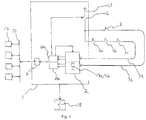
- Fig. 1
- presents as a block diagram a safety circuit of an elevator according to the invention
- Fig. 2
- presents as a block diagram a part of an input circuit according to the invention
- In the safety circuit of an elevator according to
Fig. 1 , the interface unit 1 is connected to acommunications bus 10. In addition,nodes 17 are connected to thecommunications bus 10, with which nodes the interface unit 1 communicates via thecommunications bus 10 by the aid of a communications circuit 9. The size of the interface unit 1 inFig. 1 in relation to thenodes 17 is exaggerated for illustrating the invention. In this embodiment of the invention the interface unit 1 also functions as an electronic supervision unit of the safety circuit of the elevator, which unit receives data via thecommunications bus 10 from the sensors connected to thenodes 17 and controls, if necessary, thesafety breaker 18 of the elevator. Thesafety breaker 18 is a relay, the contact of which opens when the electricity supply to the control coil of the relay ceases. The contact of the relay of thesafety breaker 18 is connected to the safety circuit of the elevator such that the electricity supply to the electromagnet of the machinery brakes of the hoisting machine (not presented inFig. 1 ) of the elevator moving the elevator car ceases and the machinery brakes activate when the contact of the relay of thesafety breaker 18 opens. In the same connection also the current supply to the electric motor of the hoisting machine is disconnected. The interface unit 1 controls the contact of the relay of thesafety breaker 18 open when it detects that the safety of the elevator is endangered. - The interface unit 1 comprises an
input circuit 2 for the measuring signal 3a, 3b of thesensors sensors - According to
Fig. 1 , thesafety switches input circuit 2 of the interface unit 1. The series circuit of switches also receives its operating voltage from the interface unit 1. In addition, inFig. 1 the safety switch 8 determining the operating status of the overspeed governor of the elevator is led separately to theinput circuit 2 of the interface unit 1. In this connection, it should be noted that the sensors/safety switches input circuit 2 can also be selected in another manner than that presented inFig. 1 . In addition, one or more of thenodes 17 connected to thecommunications bus 10 can comprise aninput circuit 2 according toFig. 1 , in which case the safety switches connected to the nodes in question can be read via the input circuit in a manner according to the invention. - A varying amount of
nodes 17 can be connected to thecommunications bus 10; one node can be fitted in connection with the elevator car (not presented inFig. 1 ), preferably on the roof of the elevator car, in which case a sensor measuring the position of the elevator car in the elevator hoistway as well as a sensor (not presented inFig. 1 ) measuring the position of the door of the elevator car can be connected to the node. One node can be fitted in the elevator hoistway (not presented inFig. 1 ), and sensors (not presented inFig. 1 ) determining the limits of the permitted movement of the elevator car in the proximity of the ends of the elevator hoistway, mechanical safety devices, such as sensors determining the operating state of end buffers, et cetera, can be fitted to the node. - According to
Fig. 1 the electricity supply to the safety switch 8 of the overspeed governor as well as to the series circuit of thesafety switches controllable switch 6. When reading the status of thesafety switches switch 6 is closed, in which case the voltage of the DC source 19 circulates via thesafety switches input circuit 2. Theinput circuit 2 comprises a pull-down resistor 13a, 13b, via which the signal path of the signal 3a, 3b circulating via thesafety switches down resistor 13a, 13b is read with a microcontroller 16a, 16b in the interface unit 1. Thesafety switches safety switches safety switches down resistor 13a, 13b in theinput circuit 2. When one of thesafety switches down resistor 13a, 13b goes to zero. Consequently, by reading the voltage over the pull-down resistor the state of the safety switch/series circuit of safety switches can be deduced. - One problem is that when reading the status of the
safety switches node 17, also the interface unit 1/node 17 reading the status of the safety switches must meet adequate safety criteria; otherwise an incorrectly determined status of the safety switch(es) might cause a dangerous situation for the user of the elevator. For example, the malfunctioning of a pull-down resistor/pull-down resistors 13a, 13b in theinput circuit 2 might result in the opening of asafety switch Fig. 1 is provided withmeans input circuit 2. In the following the testing process of the operating condition of theinput circuit 2 is described in more detail. Relating to this,Fig. 2 presents in more detail one connection of aninput circuit 2 of an interface unit 1 applicable to e.g. the embodiment ofFig. 1 . - According to
Fig. 2 , the measuring signal 3a of theseries circuit input circuit 2 via a series resistor 16. After the series resistor 16 the signal path of the signal 3a is duplicated in thenode 12 with the resistors 11a, 11b such that the first duplicated signal path 15a leaving thenode 12 travels via a first resistor 11a and the second duplicated signal path 15b leaving thenode 12 travels via a second resistor 11b. The interface unit 1 comprises two microprocessors 16a, 16b to which the duplicated signal paths leaving thenode 12 are taken such that the first duplicated signal path 15a is taken to the first microprocessor 16a and the second duplicated signal path 15b is taken to the second microprocessor 16b. Both the duplicated signal paths 15a, 15b comprise pull-upresistors 5a, 5b and also pull-down resistors 13a, 13b between the resistors 11a, 11b connecting to thenode 12 and the microprocessors. In addition, there are stillseparate series resistors 14a, 14b in the signal paths 15a, 15b before the microprocessor 16a, 16b. The pull-upresistors 5a, 5b are connected to thesignal voltage 20 withtransistors 4a, 4b for supplying testing signals to the duplicated signal paths 15a, 15b. - The
input circuit 2 also comprises a similar circuit for the measuring signal 3b of the safety switch 8 of the overspeed governor as for the measuring signal 3a of thesafety switches Fig. 2 to simplify the circuit diagram. The measuring signal 3b of the safety switch 8 of the overspeed governor is therefore taken to theinput circuit 2 in a corresponding manner such that the first microprocessor 16a reads the first duplicated signal path 15a of the signal 3b of the safety switch 8 and the second microprocessor 16b reads the second duplicated signal path 15b of the signal 3b of the safety switch 8. - The testing sequence of the operating condition of the
input circuit 2 proceeds in the following manner: at the start of the testing sequence the first microprocessor 16a controls theswitch 6 open, in which case the electricity supply from the direct-current source 19 to theseries circuit series circuit input circuit 2 has failed. After this the microprocessor 16a controls thetransistor 4a to be conductive, in which case a testing signal is supplied from thesignal voltage 20 via the pull-upresistor 5a to the first duplicated signal path 15a. The first microprocessor 16a reads the voltage from the first duplicated signal path 15a in question; if the signal path 15a in question of theinput circuit 2 is operational, the microprocessor reads a voltage corresponding to a logical "1" level. At the same time also the second microprocessor 16b reads the voltage of the same signal from the second duplicated signal path 15b. If the signal path 15b in question is operational, the second microprocessor 16b reads a voltage corresponding to a logical "0" level. Also in the rest of the duplicated signal paths of the input circuit 2 a logical "0" voltage signal is in this case read if the input circuit is in operating condition. The first 16a and the second 16b microprocessor also compare the testing results with each other, and if the testing results differ from what is permitted, i.e. if the first microcontroller 16a has read a logical "0" voltage level and/or if the second microprocessor 16b has read a logical "1" level, it is deduced that the input circuit has failed. - After this the first microprocessor 16a controls the
transistor 4a to be non-conductive and the second microprocessor 16b controls the transistor 4b to be conductive, in which case a testing signal is supplied from thesignal voltage 20 via the pull-up resistor 5b to the second duplicated signal path 15b. The second microprocessor 16b reads the voltage from the second duplicated signal path 15b in question; if the signal path in question of theinput circuit 2 is operational, the second microprocessor reads a voltage corresponding to a logical "1" level. At the same time also the first microprocessor 16a reads the voltage of the same signal from the first duplicated signal path 15a. If the signal path 15a in question is operational, the first microprocessor 16a reads a voltage corresponding to a logical "0" level. Also in the rest of the duplicated signal paths of the input circuit 2 a logical "0" voltage signal is in this case read if the input circuit is in operating condition. The first 16a and the second 16b microprocessor also compare the testing results with each other, and if the testing results differ from what is permitted, i.e. if the second microcontroller 16b has in this case read a logical "0" voltage level and/or if the first microprocessor 16a has read a logical "1" level, it is deduced that the input circuit has failed. - After this the first 16a and the second 16b microprocessor test the circuit of the duplicated signal paths of the measuring signal 3b of the safety switch 8 of the overspeed governor in the same manner.
- In addition, a test is performed in which the first 16a microprocessor controls all the
transistors 4a of the first duplicated signal paths 15a to be simultaneously conductive. In this case a logical "1" voltage level should be read from each first duplicated signal path 15a and a logical "0" voltage level should be read from each second duplicated signal path 15b; otherwise it is deduced that theinput circuit 2 has failed. After this the test is performed in a corresponding manner by controlling with the second microprocessor 16b all the transistors 4b of the second duplicated signal paths 15b to be simultaneously conductive. - Also during normal operation of the safety circuit the first 16a and the second 16b microprocessor compare the duplicated signal paths 15a, 15b of the same signal 3a, 3b; if the signal levels read from the duplicated signal paths of the same signal in this case differ from each other it is deduced that the input circuit has failed.
- When deducing that the
input circuit 2 has failed, the interface unit 1 (which is also the electronic supervision unit in the safety circuit of the elevator) sends to the elevator control unit via the communications bus 10 a control command for switching the software of the elevator system into an operating mode in which the next run of the elevator is prevented. For preventing the run, the interface unit 1 also controls a safety breaker of the elevator, which disconnects the current supply to the hoisting machine of the elevator and also activates the machinery brakes of the hoisting machine in the manner presented in the embodiment ofFig. 1 . - The invention is described above by the aid of a few examples of its embodiment. It is obvious to the person skilled in the art that the invention is not only limited to the embodiments described above, but that many other applications are possible within the scope of the inventive concept defined by the claims.
Claims (22)
- Interface unit (1) for the safety circuit of an elevator system, which interface unit (1) comprises:an input circuit (2) for the signal (3a, 3b) determining the safety of the elevator system;characterized in that the interface unit (1) comprises means (4a, 4b, 5a, 5b, 6) for testing the operating condition of the input circuit (2),wherein, when it is detected that the input circuit (2) has failed, information about the failure is sent via a communications bus (10) to an electronic supervision unit in the safety circuit, the electronic supervision unit forming a control command for switching the software of the elevator system into an operating mode in which the next run of the elevator is prevented when the electronic supervision unit receives the fault information from the communications bus (10).
- Interface unit according to claim 1, characterized in that the interface unit (1) comprises means (6) for disconnecting the signal (3a, 3b) determining the safety of the elevator system;
and in that the interface unit (1) is configured to determine the operating condition of the input circuit (2) when the signal (3a, 3b) determining the safety of the elevator system has been disconnected. - Interface unit according to claim 2, characterized in that the aforementioned signal (3a, 3b) determining the safety of the elevator system is formed with a sensor (7a, 7b, 7c, 8) measuring a safety-critical property of the elevator system;
and in that the means (6) for disconnecting the signal determining the safety of the elevator system is configured to disconnect the electricity supply of the sensor (7a, 7b, 7c, 8) measuring a safety-critical property of the elevator system. - Interface unit according to claim 1, characterized in that the interface unit (1) comprises means (4a, 4b, 5a, 5b) for supplying a testing signal to the input circuit (2).
- Interface unit according to claim 4, characterized in that the interface unit (1) is configured to supply a testing signal to the input circuit (2) when the signal (3a, 3b) determining the safety of the elevator system has been disconnected.
- Interface unit according to claim 1, characterized in that the interface unit (1) comprises a communications circuit (9) for sending a message to the communications bus (10) in the safety circuit of the elevator system.
- Interface unit according to claim 1, characterized in that the input circuit (2) comprises a node (12) for duplicating the signal path of a signal (3a, 3b) arriving in the input circuit.
- Interface unit according to claim 7, characterized in that the interface unit (1) comprises two signal-processing elements (16a, 16b);
and in that of the duplicated signal paths the first (15a) is taken to the first signal-processing element (16a) and the second (15b) is taken to the second signal-processing element (16b). - Interface unit according to claim 7, characterized in that the interface unit (1) is configured to supply the first testing signal to the first (15a) of duplicated signal paths and the second testing signal to the second (15b) of the duplicated signal paths.
- Interface unit according to claim 9, characterized in that the interface unit (1) is configured to supply a testing signal in turn to both of the duplicated signal paths (15a, 15b).
- Interface unit according to claim 7, characterized in that the interface unit (1) is configured to determine a fault situation in the input circuit (2), if the first testing signal supplied to the first (15a) of duplicated signal paths causes a change that is larger than permitted in the second (15b) of the duplicated signal paths.
- Interface unit according to claim 7, characterized in that the interface unit (1) is configured to determine a fault situation in the input circuit (2), if the first testing signal supplied to the first (15a) of duplicated signal paths causes a change that is smaller than permitted in the first (15a) of the duplicated signal paths.
- Interface unit according to claim 1, characterized in that the input circuit (2) comprises a connection for two or more signals (3a, 3b) determining the safety of the elevator system;
and in that the interface unit (1) is configured to determine in turn the operating condition of the signal path of each different signal arriving in the input circuit (2). - Interface unit according to claim 13, characterized in that the interface unit (1) is configured to determine the operating condition of the input circuit (2) when all the signals arriving in the input circuit (2) that determine the safety of the elevator system have been disconnected.
- Interface unit according to any of the preceding claims, characterized in that a safety switch (8) and/or a series circuit (7a, 7b, 7c) of safety switches is connected to the aforementioned input circuit (2).
- Elevator system, characterized in that the elevator system comprises an interface unit according to any of claims 1 - 15 for the safety circuit of the elevator system.
- Method for monitoring the operating condition of an input circuit (2) in the safety circuit of an elevator system, characterized in that:- the operating condition of the input circuit (2) is monitored with means (4a, 4b, 5a, 5b, 6) fitted in connection with the input circuit (2), wherein, when it is detected that the input circuit (2) has failed, information about the failure is sent via a communications bus (10) to an electronic supervision unit in the safety circuit, the electronic supervision unit forming a control command for switching the software of the elevator system into an operating mode in which the next run of the elevator is prevented when the electronic supervision unit receives the fault information from the communications bus (10).
- Method according to claim 17, characterized in that:- a signal (3a, 3b) to be supplied to the input circuit (2), said signal determining the safety of the elevator system, is disconnected- the operating condition of the input circuit (2) is determined when the aforementioned signal (3a, 3b) determining the safety of the elevator system has been disconnected.
- Method according to claim 18, characterized in that:- the signal (3a, 3b) to be supplied to the input circuit (2) is disconnected by disconnecting the electricity supply of a sensor (7a, 7b, 7c, 8) measuring a safety-critical property of the elevator system.
- Method according to claim 18, characterized in that:- a testing signal is supplied to the input circuit (2) when the aforementioned signal (3a, 3b) determining the safety of the elevator system has been disconnected.
- Method according to claim 20, characterized in that:- the signal path of the arriving signal (3a, 3b) is duplicated in the input circuit (2);- a testing signal is supplied in turn to both of the duplicated signal paths (15a, 15b).
- Method according to any of claims 17 - 21, characterized in that:- a safety switch (8) and/or a series circuit (7a, 7b, 7c) of safety switches is connected to the input circuit (2).
Applications Claiming Priority (3)
| Application Number | Priority Date | Filing Date | Title |
|---|---|---|---|
| FI20106319A FI122473B (en) | 2010-12-14 | 2010-12-14 | Interface, transport system and method |
| EP11848231.4A EP2651806B1 (en) | 2010-12-14 | 2011-12-08 | Conveying system |
| PCT/FI2011/000052 WO2012080560A1 (en) | 2010-12-14 | 2011-12-08 | Interface unit, conveying system and method |
Related Parent Applications (2)
| Application Number | Title | Priority Date | Filing Date |
|---|---|---|---|
| EP11848231.4A Division-Into EP2651806B1 (en) | 2010-12-14 | 2011-12-08 | Conveying system |
| EP11848231.4A Division EP2651806B1 (en) | 2010-12-14 | 2011-12-08 | Conveying system |
Publications (2)
| Publication Number | Publication Date |
|---|---|
| EP3653559A2 true EP3653559A2 (en) | 2020-05-20 |
| EP3653559A3 EP3653559A3 (en) | 2020-09-16 |
Family
ID=43415009
Family Applications (2)
| Application Number | Title | Priority Date | Filing Date |
|---|---|---|---|
| EP11848231.4A Active EP2651806B1 (en) | 2010-12-14 | 2011-12-08 | Conveying system |
| EP19215540.6A Pending EP3653559A3 (en) | 2010-12-14 | 2011-12-08 | Interface unit, elevator system and method |
Family Applications Before (1)
| Application Number | Title | Priority Date | Filing Date |
|---|---|---|---|
| EP11848231.4A Active EP2651806B1 (en) | 2010-12-14 | 2011-12-08 | Conveying system |
Country Status (10)
| Country | Link |
|---|---|
| US (2) | US9448273B2 (en) |
| EP (2) | EP2651806B1 (en) |
| JP (2) | JP6105482B2 (en) |
| CN (2) | CN105293234B (en) |
| AU (1) | AU2011343126B2 (en) |
| ES (1) | ES2805729T3 (en) |
| FI (1) | FI122473B (en) |
| HK (2) | HK1186452A1 (en) |
| RU (2) | RU2604633C2 (en) |
| WO (1) | WO2012080560A1 (en) |
Families Citing this family (16)
| Publication number | Priority date | Publication date | Assignee | Title |
|---|---|---|---|---|
| EP2697146B1 (en) * | 2011-04-15 | 2020-10-21 | Otis Elevator Company | Elevator drive power supply control |
| EP2930134B1 (en) * | 2014-04-09 | 2018-05-30 | Kone Corporation | Safety system and method for testing safety critical components in an elevator system |
| GB2526138A (en) * | 2014-05-15 | 2015-11-18 | Control Tech Ltd | Diagnostics and control circuit |
| EP3012217B8 (en) * | 2014-10-21 | 2017-08-02 | KONE Corporation | Safety system for elevator |
| ES2713174T3 (en) * | 2014-12-17 | 2019-05-20 | Inventio Ag | Safety switching device for an elevator installation |
| AU2016257307B2 (en) * | 2015-05-05 | 2019-05-02 | Inventio Ag | Lift monitoring unit having a galvanically decoupled signal transmission |
| SG11201710251UA (en) * | 2015-06-10 | 2018-01-30 | Inventio Ag | Lift system with predictive call production |
| ES2714352T3 (en) * | 2015-10-07 | 2019-05-28 | Kone Corp | Sensor connection unit, safety system and elevator |
| DE102016106531A1 (en) * | 2016-04-08 | 2017-10-12 | Eaton Electrical Ip Gmbh & Co. Kg | Bus subscriber and method for operating a bus subscriber |
| CN106698117B (en) * | 2016-12-05 | 2019-04-26 | 西继迅达(许昌)电梯有限公司 | A kind of elevator control system and door lock of elevator shunting device control panel |
| CN106744114A (en) * | 2016-12-28 | 2017-05-31 | 江苏省特种设备安全监督检验研究院 | Elevator running environment monitoring system |
| CN107884674A (en) * | 2017-11-20 | 2018-04-06 | 国网河南省电力公司驻马店供电公司 | 10kv distribution line high voltage link fuse melting warning systems |
| US10351392B1 (en) * | 2018-10-23 | 2019-07-16 | Otis Elevator Company | Escalator and moving walkway system with safety sensor |
| JP6885418B2 (en) * | 2019-04-08 | 2021-06-16 | フジテック株式会社 | Passenger conveyor |
| US11492117B2 (en) * | 2019-06-10 | 2022-11-08 | Goodrich Corporation | Dual bus architecture for high reliability control of helicopter hoist |
| CN111532925B (en) * | 2020-03-27 | 2021-10-22 | 日立电梯(中国)有限公司 | Elevator power supply protection method |
Family Cites Families (27)
| Publication number | Priority date | Publication date | Assignee | Title |
|---|---|---|---|---|
| JPS5936079A (en) * | 1982-08-18 | 1984-02-28 | 株式会社東芝 | Controller for elevator |
| US4898263A (en) * | 1988-09-12 | 1990-02-06 | Montgomery Elevator Company | Elevator self-diagnostic control system |
| JPH0747460B2 (en) * | 1990-03-02 | 1995-05-24 | 株式会社日立製作所 | Control device for passenger compare |
| US5407028A (en) | 1993-04-28 | 1995-04-18 | Otis Elevator Company | Tested and redundant elevator emergency terminal stopping capability |
| ES2192724T3 (en) * | 1997-09-22 | 2003-10-16 | Inventio Ag | CONTROL DEVICE FOR AN ELEVATOR OPERATING CONTROL. |
| SG85215A1 (en) * | 1999-10-08 | 2001-12-19 | Inventio Ag | Safety circuit for an elevator installation |
| US6267219B1 (en) * | 2000-08-11 | 2001-07-31 | Otis Elevator Company | Electronic safety system for escalators |
| US6543583B1 (en) * | 2001-07-02 | 2003-04-08 | Otis Elevator Company | Elevator auditing with recommended action, reason and severity in maintenance messages |
| US6467585B1 (en) * | 2001-07-05 | 2002-10-22 | Otis Elevator Company | Wireless safety chain for elevator system |
| KR100498043B1 (en) * | 2002-12-13 | 2005-07-01 | 삼성전자주식회사 | Digital Camera and control method thereof |
| EP1638880B2 (en) * | 2003-06-30 | 2013-07-24 | Inventio AG | Safety system for an elevator structure |
| WO2005049467A1 (en) * | 2003-11-19 | 2005-06-02 | Mitsubishi Denki Kabushiki Kaisha | Elevator controller |
| PT1719729E (en) * | 2004-02-26 | 2011-06-29 | Mitsubishi Electric Corp | Safety device of elevator |
| DE102004050647B4 (en) * | 2004-10-18 | 2014-11-20 | Siemens Aktiengesellschaft | Monitoring method for a drive device to a standstill, hereby corresponding monitoring device and hereby corresponding drive system |
| FI116937B (en) * | 2004-11-01 | 2006-04-13 | Kone Corp | Elevator test system |
| JP4757863B2 (en) * | 2005-02-25 | 2011-08-24 | 三菱電機株式会社 | Elevator equipment |
| FI117797B (en) * | 2005-04-08 | 2007-02-28 | Kone Corp | Elevator system |
| AT502582B1 (en) * | 2005-09-20 | 2008-05-15 | Tuev Oesterreich Tech Ueberwac | MONITORING EQUIPMENT OF AN ELEVATOR |
| FI119508B (en) * | 2007-04-03 | 2008-12-15 | Kone Corp | Fail safe power control equipment |
| FI119807B (en) * | 2007-11-30 | 2009-03-31 | Kone Corp | Elevator standby |
| JP5517432B2 (en) * | 2008-10-16 | 2014-06-11 | 三菱電機株式会社 | Elevator safety system |
| TW201020873A (en) * | 2008-11-21 | 2010-06-01 | Ideacom Technology Corp | Apparatus for testing electronic system with 4-wires resistive touch panel and the method therefor |
| US8552738B2 (en) * | 2008-11-27 | 2013-10-08 | Inventio Ag | Device for checking a safety circuit of an elevator |
| CN102341333B (en) * | 2009-03-13 | 2015-06-10 | 三菱电机株式会社 | Elevator device |
| FI121423B (en) * | 2009-04-23 | 2010-11-15 | Kone Corp | Safety arrangement for a lift |
| FI20105033A (en) * | 2010-01-18 | 2011-07-19 | Kone Corp | Procedure for controlling the movement of a lift basket and lift system |
| WO2011111223A1 (en) * | 2010-03-12 | 2011-09-15 | 三菱電機株式会社 | Elevator safety control device |
-
2010
- 2010-12-14 FI FI20106319A patent/FI122473B/en active
-
2011
- 2011-12-08 CN CN201510644726.3A patent/CN105293234B/en active Active
- 2011-12-08 EP EP11848231.4A patent/EP2651806B1/en active Active
- 2011-12-08 EP EP19215540.6A patent/EP3653559A3/en active Pending
- 2011-12-08 JP JP2013543843A patent/JP6105482B2/en active Active
- 2011-12-08 WO PCT/FI2011/000052 patent/WO2012080560A1/en unknown
- 2011-12-08 AU AU2011343126A patent/AU2011343126B2/en active Active
- 2011-12-08 ES ES11848231T patent/ES2805729T3/en active Active
- 2011-12-08 CN CN201180067589.1A patent/CN103370269B/en active Active
- 2011-12-08 RU RU2013126972/11A patent/RU2604633C2/en active
- 2011-12-08 RU RU2016126435A patent/RU2716410C2/en active
-
2013
- 2013-06-10 US US13/913,884 patent/US9448273B2/en active Active
- 2013-12-18 HK HK13114015.7A patent/HK1186452A1/en unknown
- 2013-12-18 HK HK16105690.4A patent/HK1217682A1/en unknown
-
2015
- 2015-11-09 JP JP2015219217A patent/JP6105704B2/en not_active Expired - Fee Related
-
2016
- 2016-03-07 US US15/063,084 patent/US10114066B2/en active Active
Also Published As
| Publication number | Publication date |
|---|---|
| US10114066B2 (en) | 2018-10-30 |
| JP6105704B2 (en) | 2017-03-29 |
| CN103370269B (en) | 2016-05-18 |
| HK1217682A1 (en) | 2017-01-20 |
| ES2805729T3 (en) | 2021-02-15 |
| EP2651806A4 (en) | 2016-08-03 |
| EP2651806B1 (en) | 2020-06-24 |
| US20130271152A1 (en) | 2013-10-17 |
| CN103370269A (en) | 2013-10-23 |
| US9448273B2 (en) | 2016-09-20 |
| RU2604633C2 (en) | 2016-12-10 |
| CN105293234B (en) | 2018-01-09 |
| EP2651806A1 (en) | 2013-10-23 |
| RU2016126435A3 (en) | 2019-10-09 |
| HK1186452A1 (en) | 2014-03-14 |
| US20160185570A1 (en) | 2016-06-30 |
| JP6105482B2 (en) | 2017-03-29 |
| RU2013126972A (en) | 2015-01-20 |
| AU2011343126A1 (en) | 2013-06-27 |
| AU2011343126B2 (en) | 2016-11-17 |
| WO2012080560A1 (en) | 2012-06-21 |
| RU2016126435A (en) | 2018-12-05 |
| JP2014504243A (en) | 2014-02-20 |
| FI122473B (en) | 2012-02-15 |
| CN105293234A (en) | 2016-02-03 |
| FI20106319A0 (en) | 2010-12-14 |
| JP2016041631A (en) | 2016-03-31 |
| RU2716410C2 (en) | 2020-03-11 |
| EP3653559A3 (en) | 2020-09-16 |
Similar Documents
| Publication | Publication Date | Title |
|---|---|---|
| US10114066B2 (en) | Interface unit, conveying system and method | |
| EP2125591B1 (en) | Safety arrangement | |
| KR101268755B1 (en) | Door control system for railroad vehicle | |
| CN108217357B (en) | Elevator safety system, elevator system and method for operating elevator system | |
| US9367416B2 (en) | Safety circuit of an elevator, and method for identifying a functional nonconformance of a safety circuit of an elevator | |
| CN108394775B (en) | Elevator safety system and safety control method | |
| CN101048331B (en) | Elevator testing system | |
| CN106687403B (en) | Elevator brake control system | |
| JP2005162482A (en) | Elevator equipment and monitoring system for elevator equipment | |
| CN107640671A (en) | Door lock short-circuit detecting device | |
| US20200346893A1 (en) | Safety monitoring device for monitoring safety-related states in a passenger conveyor system and method for operating same | |
| WO2015151256A1 (en) | Elevator control device | |
| CN113460823B (en) | Door lock short-circuit fault diagnosis system, method, equipment and storage medium | |
| JP6625964B2 (en) | Lift control device and lift control method | |
| KR0167209B1 (en) | Helping out operation control method and equipment for elevator | |
| KR970004767B1 (en) | Auxiliary operation control circuit of elevator and method of the same |
Legal Events
| Date | Code | Title | Description |
|---|---|---|---|
| PUAI | Public reference made under article 153(3) epc to a published international application that has entered the european phase |
Free format text: ORIGINAL CODE: 0009012 |
|
| STAA | Information on the status of an ep patent application or granted ep patent |
Free format text: STATUS: THE APPLICATION HAS BEEN PUBLISHED |
|
| AC | Divisional application: reference to earlier application |
Ref document number: 2651806 Country of ref document: EP Kind code of ref document: P |
|
| AK | Designated contracting states |
Kind code of ref document: A2 Designated state(s): AL AT BE BG CH CY CZ DE DK EE ES FI FR GB GR HR HU IE IS IT LI LT LU LV MC MK MT NL NO PL PT RO RS SE SI SK SM TR |
|
| PUAL | Search report despatched |
Free format text: ORIGINAL CODE: 0009013 |
|
| AK | Designated contracting states |
Kind code of ref document: A3 Designated state(s): AL AT BE BG CH CY CZ DE DK EE ES FI FR GB GR HR HU IE IS IT LI LT LU LV MC MK MT NL NO PL PT RO RS SE SI SK SM TR |
|
| RIC1 | Information provided on ipc code assigned before grant |
Ipc: G01R 31/28 20060101ALI20200807BHEP Ipc: G05B 15/02 20060101ALI20200807BHEP Ipc: B66B 5/00 20060101AFI20200807BHEP |
|
| STAA | Information on the status of an ep patent application or granted ep patent |
Free format text: STATUS: REQUEST FOR EXAMINATION WAS MADE |
|
| 17P | Request for examination filed |
Effective date: 20210414 |
|
| RBV | Designated contracting states (corrected) |
Designated state(s): AL AT BE BG CH CY CZ DE DK EE ES FI FR GB GR HR HU IE IS IT LI LT LU LV MC MK MT NL NO PL PT RO RS SE SI SK SM TR |
|
| STAA | Information on the status of an ep patent application or granted ep patent |
Free format text: STATUS: EXAMINATION IS IN PROGRESS |
|
| 17Q | First examination report despatched |
Effective date: 20221006 |
|
| P01 | Opt-out of the competence of the unified patent court (upc) registered |
Effective date: 20230525 |